
Ce Aw 004101
265
CEAW004101 Field Assembly Manual DUMP TRUCK SERIAL NUMBERS A 30427 & UP ®
-
Upload
ravinder-singh -
Category
Documents
-
view
217 -
download
0
Transcript of Ce Aw 004101

8/17/2019 Ce Aw 004101
http://slidepdf.com/reader/full/ce-aw-004101 1/265
CEAW004101
Field Assembly
Manual
DUMP TRUCK
SERIAL NUMBERS A30427 & UP
®

8/17/2019 Ce Aw 004101
http://slidepdf.com/reader/full/ce-aw-004101 2/265

8/17/2019 Ce Aw 004101
http://slidepdf.com/reader/full/ce-aw-004101 3/265
FAM0011 Introduction
FOREWARD
This manual is provided to aid assemblers during field assembly of the standard Komatsu 730E dump truck.
Variations of design required for specific truck orders may require some modification of the general procedures out
lined in this manual. Follow all safety notices, warnings, and cautions provided in this book when assembling the
truck.
General assembly pictures and illustrations are used in this manual. At times the illustrations may not reflect thecurrent production truck model.
This manual lists metric (SI) and U.S. standard dimensions throughout.
All location references to “front”, “rear”, “right”, or “left”, are given in respect to the operator's normal seated posi-
tion.
It is recommended that all maintenance personnel read and understand the materials in the service manual before
performing maintenance and/or operational checks on the assembled truck.

8/17/2019 Ce Aw 004101
http://slidepdf.com/reader/full/ce-aw-004101 4/265
ii Introduction FAM0011
This “ALERT” symbol is used with the signal words,
“ CAUTION” , “DANGER” , and “ WARNING” in this manual
to alert the reader to hazards arising from improper oper-
ating and maintenance practices.
“ DANGER” identifies a specific potential hazard
WHICH WILL RESULT
in either INJURY OR DEATH
if proper precautions are not taken.
“ WARNING” identifies a specific potential hazard
WHICH WILL RESULT
in either INJURY OR DEATH
if proper precautions are not taken.
“ CAUTION” is used for general reminders
of proper safety practices
OR
to direct the reader’s attention to avoid unsafe
or improper practices which may result
in damage to the equipment.

8/17/2019 Ce Aw 004101
http://slidepdf.com/reader/full/ce-aw-004101 5/265
FAM0011 Introduction ii
TABLE OF CONTENTS
SUBJECT PAGE NUMBER
FOREWORD . . . . . . . . . . . . . . . . . . . . . . . . . . . . . . . . . . . . . . . . . . . . . . . . . . . . . . . . . . . . . . . . . . . . . . . . . . . . . . .
SAFETY RULES, TOOLS & EQUIPMENT . . . . . . . . . . . . . . . . . . . . . . . . . . . . . . . . . . . . . . . . . . . . . . . . . . . . . . 1-1
MAJOR COMPONENTS AND SPECIFICATIONS . . . . . . . . . . . . . . . . . . . . . . . . . . . . . . . . . . . . . . . . . . . . . . . . 2-1
MAJOR COMPONENT WEIGHTS . . . . . . . . . . . . . . . . . . . . . . . . . . . . . . . . . . . . . . . . . . . . . . . . . . . . . . . . . . . . 3-1
FIELD WELDING FOR ASSEMBLY OR REPAIR . . . . . . . . . . . . . . . . . . . . . . . . . . . . . . . . . . . . . . . . . . . . . . . . . 4-
RECEIVING AND ASSEMBLY PREPARATION . . . . . . . . . . . . . . . . . . . . . . . . . . . . . . . . . . . . . . . . . . . . . . . . . . 5-1
CHASSIS ASSEMBLY. . . . . . . . . . . . . . . . . . . . . . . . . . . . . . . . . . . . . . . . . . . . . . . . . . . . . . . . . . . . . . . . . . . . . . 6-
DUMP BODY ASSEMBLY . . . . . . . . . . . . . . . . . . . . . . . . . . . . . . . . . . . . . . . . . . . . . . . . . . . . . . . . . . . . . . . . . . 7-
DUMP BODY INSTALLATION . . . . . . . . . . . . . . . . . . . . . . . . . . . . . . . . . . . . . . . . . . . . . . . . . . . . . . . . . . . . . . . 8-1
FINAL CHECK-OUT . . . . . . . . . . . . . . . . . . . . . . . . . . . . . . . . . . . . . . . . . . . . . . . . . . . . . . . . . . . . . . . . . . . . . . . 9-1
APPENDIX . . . . . . . . . . . . . . . . . . . . . . . . . . . . . . . . . . . . . . . . . . . . . . . . . . . . . . . . . . . . . . . . . . . . . . . . . . . . . 10-

8/17/2019 Ce Aw 004101
http://slidepdf.com/reader/full/ce-aw-004101 6/265
iv Introduction FAM0011
KOMATSU MODEL 730E DUMP TRUCK

8/17/2019 Ce Aw 004101
http://slidepdf.com/reader/full/ce-aw-004101 7/265
FAM0109 Safety Rules, Tools, & Equipment Page 1-1
SAFETY RULES, TOOLS & EQUIPMENT
SAFETY RULES
The following list of safety practices is intended for
use by personnel during field assembly of the truck.
This list of safety rules is not intended to replace local
safety rules or regulations and federal, state, or local
laws. The safety precautions recommended here are
general and must be used in conjunction with all pre-
vailing local rules and regulations.
1. All personnel must be properly trained for the
assembly operation.
2. Wear safety equipment such as safety glasses,
hard toe shoes and hard hats at all times during
assembly.
3. Thoroughly inspect the assembly site. Remove
weeds, debris and other flammable material.
4. Use only solid, hard wood for supports. When
using metal support stands, place wood blocksbetween the support and the frame to prevent
metal to metal contact.
5. Inspect all lifting devices. Refer to the manufac-
turer's specifications for correct capacities and
safety procedures when lifting components.
6. Perform a daily inspection of all lifting cables
and chains. Replace any questionable items.
Use cables and chains that are properly rated
for the load to be lifted.
7. DO NOT stand beneath a suspended load. Use
of guy ropes are recommended for guiding and
positioning a suspended load.8. Maintain fire control equipment. Inspect fire
extinguishers regularly to ensure they are fully
charged and in good working condition.
9. Cap screws and/or nuts being replaced must be
the same grade as originally supplied.
10. Disconnect the battery charging alternator lead
wire before welding on the frame or its compo-
nents.
11. When welding, connect the ground cable to the
part being welded. DO NOT allow welding cur-
rent to pass through bearings, engine, etc.
12. DO NOT weld the transmission housing unless
it has been completely disassembled.
13. DO NOT weld the fuel tank or hydraulic tank
unless the tanks have been properly purged
and ventilated.
14. Use the proper tools for the job to be performed
Never improvise wrenches, screw drivers, sock-
ets, etc. unless specified.
15. Lifting eyes and hooks must be fabricated from
the proper materials and rated to lift the
intended load.
16. When the weight of any component(s) or any
assembly procedure is not known, contact yourcustomer support manager for further informa-
tion.
8/17/2019 Ce Aw 004101
http://slidepdf.com/reader/full/ce-aw-004101 8/265
Page1-2 Safety Rules, Tools, & Equipment FAM0109
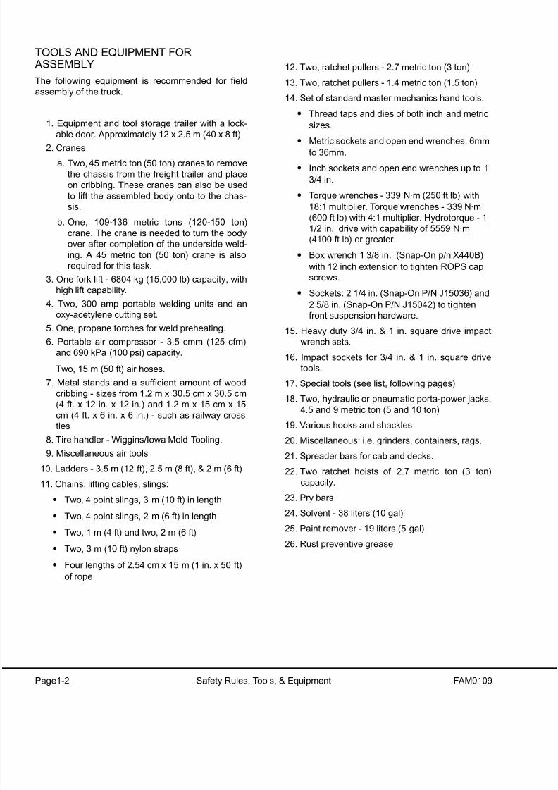
TOOLS AND EQUIPMENT FOR ASSEMBLY
The following equipment is recommended for field
assembly of the truck.
1. Equipment and tool storage trailer with a lock-
able door. Approximately 12 x 2.5 m (40 x 8 ft)2. Cranes
a. Two, 45 metric ton (50 ton) cranes to remove
the chassis from the freight trailer and place
on cribbing. These cranes can also be used
to lift the assembled body onto to the chas-
sis.
b. One, 109-136 metric tons (120-150 ton)
crane. The crane is needed to turn the body
over after completion of the underside weld-
ing. A 45 metric ton (50 ton) crane is also
required for this task.
3. One fork lift - 6804 kg (15,000 lb) capacity, withhigh lift capability.
4. Two, 300 amp portable welding units and an
oxy-acetylene cutting set.
5. One, propane torches for weld preheating.
6. Portable air compressor - 3.5 cmm (125 cfm)
and 690 kPa (100 psi) capacity.
Two, 15 m (50 ft) air hoses.
7. Metal stands and a sufficient amount of wood
cribbing - sizes from 1.2 m x 30.5 cm x 30.5 cm
(4 ft. x 12 in. x 12 in.) and 1.2 m x 15 cm x 15
cm (4 ft. x 6 in. x 6 in.) - such as railway crossties
8. Tire handler - Wiggins/Iowa Mold Tooling.
9. Miscellaneous air tools
10. Ladders - 3.5 m (12 ft), 2.5 m (8 ft), & 2 m (6 ft)
11. Chains, lifting cables, slings:
• Two, 4 point slings, 3 m (10 ft) in length
• Two, 4 point slings, 2 m (6 ft) in length
• Two, 1 m (4 ft) and two, 2 m (6 ft)
• Two, 3 m (10 ft) nylon straps
• Four lengths of 2.54 cm x 15 m (1 in. x 50 ft)
of rope
12. Two, ratchet pullers - 2.7 metric ton (3 ton)
13. Two, ratchet pullers - 1.4 metric ton (1.5 ton)
14. Set of standard master mechanics hand tools.
• Thread taps and dies of both inch and metric
sizes.
• Metric sockets and open end wrenches, 6mmto 36mm.
• Inch sockets and open end wrenches up to 1
3/4 in.
• Torque wrenches - 339 N·m (250 ft lb) with
18:1 multiplier. Torque wrenches - 339 N·m
(600 ft lb) with 4:1 multiplier. Hydrotorque - 1
1/2 in. drive with capability of 5559 N·m
(4100 ft lb) or greater.
• Box wrench 1 3/8 in. (Snap-On p/n X440B)
with 12 inch extension to tighten ROPS cap
screws.
• Sockets: 2 1/4 in. (Snap-On P/N J15036) and
2 5/8 in. (Snap-On P/N J15042) to tighten
front suspension hardware.
15. Heavy duty 3/4 in. & 1 in. square drive impact
wrench sets.
16. Impact sockets for 3/4 in. & 1 in. square drive
tools.
17. Special tools (see list, following pages)
18. Two, hydraulic or pneumatic porta-power jacks,
4.5 and 9 metric ton (5 and 10 ton)
19. Various hooks and shackles
20. Miscellaneous: i.e. grinders, containers, rags.
21. Spreader bars for cab and decks.
22. Two ratchet hoists of 2.7 metric ton (3 ton)
capacity.
23. Pry bars
24. Solvent - 38 liters (10 gal)
25. Paint remover - 19 liters (5 gal)
26. Rust preventive grease
8/17/2019 Ce Aw 004101
http://slidepdf.com/reader/full/ce-aw-004101 9/265
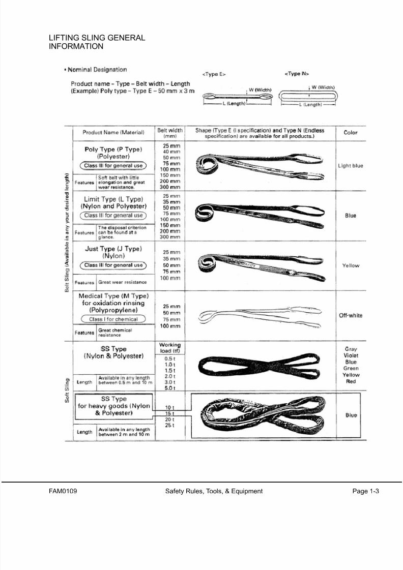
FAM0109 Safety Rules, Tools, & Equipment Page 1-3
LIFTING SLING GENERALINFORMATION
8/17/2019 Ce Aw 004101
http://slidepdf.com/reader/full/ce-aw-004101 10/265
Page1-4 Safety Rules, Tools, & Equipment FAM0109
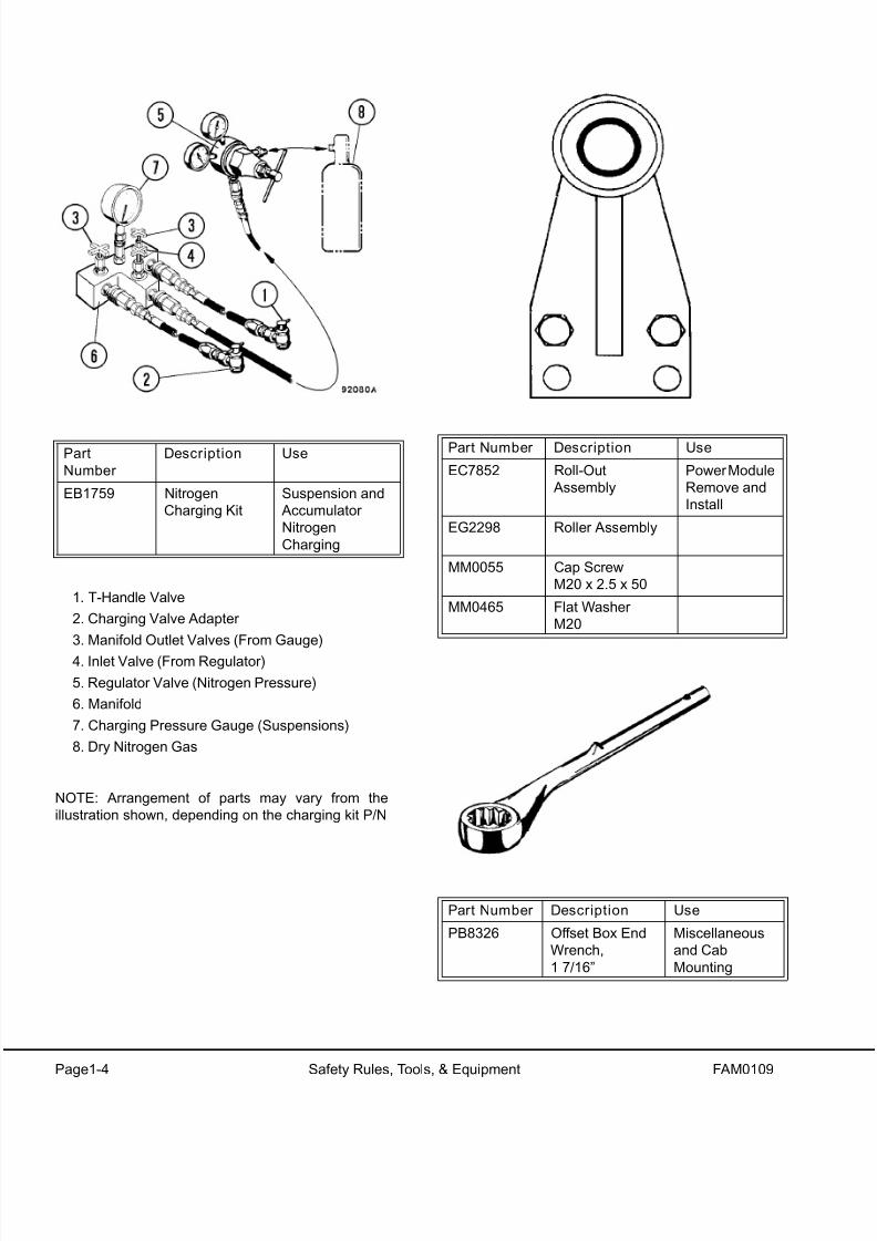
1. T-Handle Valve
2. Charging Valve Adapter
3. Manifold Outlet Valves (From Gauge)
4. Inlet Valve (From Regulator)
5. Regulator Valve (Nitrogen Pressure)
6. Manifold
7. Charging Pressure Gauge (Suspensions)
8. Dry Nitrogen Gas
NOTE: Arrangement of parts may vary from the
illustration shown, depending on the charging kit P/N
Part
Number
Description Use
EB1759 Nitrogen
Charging Kit
Suspension and
Accumulator
Nitrogen
Charging
Part Number Description Use
EC7852 Roll-Out
Assembly
Power Module
Remove and
Install
EG2298 Roller Assembly
MM0055 Cap Screw
M20 x 2.5 x 50
MM0465 Flat Washer
M20
Part Number Description Use
PB8326 Offset Box End
Wrench,
1 7/16”
Miscellaneous
and Cab
Mounting

8/17/2019 Ce Aw 004101
http://slidepdf.com/reader/full/ce-aw-004101 11/265
FAM0109 Safety Rules, Tools, & Equipment Page 1-5
Part Number Description Use
TZ2734 3/4” Torque
Adapter
Miscellaneous
Part Number Description Use
TZ2733 Tubular Handle Use with
PB8326 and
TZ2734
Part Number Description Use
TY2150 Seal Installa-
tion Tool
Installation of
Front Wheel
Bearing FaceSeals
Part Number Description Use
EC1741
EC1742
TZ0992
Sleeve
Alignment Tool
Steering Linkage
and Tie Rod
Assembly. Refer
to Section G.

8/17/2019 Ce Aw 004101
http://slidepdf.com/reader/full/ce-aw-004101 12/265
Page1-6 Safety Rules, Tools, & Equipment FAM0109
Part Number Description Use
AK4720 Payload Data
Manger
Payload Meter
Download. Refer
to Section D.EF9160 PLM Download
Harness
Part Number Description Use
PB6039 Hydraulic
Coupling
Miscellaneous
Part Number Description UseTG1106 Eye Bolt Miscellaneous
Lifting
Requirements
Part Number Description Use
TW9425 Special Wrench Accumulator
Gland Nut
PART NO. DESCRIPTION USEPC2061 Belt Tension
Tester
A/C Belt Tension

8/17/2019 Ce Aw 004101
http://slidepdf.com/reader/full/ce-aw-004101 13/265
FAM0109 Safety Rules, Tools, & Equipment Page 1-7
Part
Number
Description Use
TZ8968 Socket 3-1/2” Miscellaneous
TZ2726 Socket 1-1/8” Miscellaneous
TZ2729 Socket 1-1/4” Miscellaneous
TV7567 Socket 1-5/16” Miscellaneous
PB6825 Impact Socket 1-5/8” Miscellaneous
TR0529 Socket 1-3/4” Miscellaneous
TZ2100 Socket 1-7/8” Miscellaneous
TZ2727 Socket 2-1/4” Miscellaneous
TZ2728 Socket 2-3/4” Miscellaneous
PB6824 Impact Socket 3-1/8” Miscellaneous
TZ8968 Socket 3-1/2” MiscellaneousTR0532 Square Drive
Extension 8”
Miscellaneous
TR0533 Square Drive
Extension 17”
Miscellaneous
TV1186 Extension 3-1/2” Miscellaneous
TR0546 Sliding T-Handle Miscellaneous
TZ2730 Adapter 1” x 1-1/2” Miscellaneous
TZ2731 Adapter 3/4” x 1” Miscellaneous
PB6851 Locking Steel Pin (for
use with 1-1/2”
square drivesockets)
Miscellaneous
PB6852 Locking Rubber Ring
(for use with 1-1/2”
square drive
sockets)
Miscellaneous
PART NO. DESCRIPTION USE
EL8868 V-Belt Align-
ment Tool
Aligning A/C
pulleys

8/17/2019 Ce Aw 004101
http://slidepdf.com/reader/full/ce-aw-004101 14/265
Page1-8 Safety Rules, Tools, & Equipment FAM0109
A S S E M B L Y S C
H E D U L E A N D
R E S O U R C E
L A Y O U T

8/17/2019 Ce Aw 004101
http://slidepdf.com/reader/full/ce-aw-004101 15/265
FAM0109 Safety Rules, Tools, & Equipment Page 1-9

8/17/2019 Ce Aw 004101
http://slidepdf.com/reader/full/ce-aw-004101 16/265
Page1-10 Safety Rules, Tools, & Equipment FAM0109
NOTES

8/17/2019 Ce Aw 004101
http://slidepdf.com/reader/full/ce-aw-004101 17/265
FAM0210 Major Components & Specifications FAM2-1
MAJOR COMPONENTS AND SPECIFICATIONS
The Komatsu model 730E dump truck is an electric drive, off-highway, rear dump truck. Standard 730E gross vehi
cle weight is 324,322 kg (715,000 lbs) rated for a nominal payload of 185 t (203 tons). Some Trolley versions may
have a higher GVW. Refer to the grade/speed chart in the operator’s cab for the appropriate GVW.
ENGINE
The Komatsu 730E dump truck is powered by a
Komatsu SSA16V159 engine rated at 2000 HP(1492 kW).
ALTERNATOR (GE GTA-22)
The diesel engine drives an alternator mounted in-
line with the engine. The Alternating Current (AC)
output of the alternator is rectified to Direct Current
(DC) and sent to the DC drive wheel motors.
WHEEL MOTORS (GE 788)
The output of the alternator supplies electrical energy
to the two wheel motors attached to the rear axle
housing. The two wheel motors convert electricalenergy back to mechanical energy through built-in
gear trains within the wheel motor assembly. The
direction of the wheel motors is controlled by a for-
ward or reverse hand selector switch located on a
console to the right side of the operator.
BLOWER
The blower supplies cooling air for the rectifiers, AC
alternator, and to both wheel motors, where it is then
exhausted to the atmosphere.
OPERATOR'S CABThe operator's cab for the Komatsu 730E dump truck
has been engineered for operator comfort and to
allow for efficient and safe operation of the truck.
The cab provides for wide visibility, with an integral
four-post Rollover Protective Structure/Falling Object
Protective Structure (ROPS/FOPS), and an
advanced analog operator environment. It includes a
tinted safety-glass windshield and power-operated
side windows, a deluxe interior with a fully adjustable
seat with lumbar support, a fully adjustable/tilt steer-
ing wheel, controls mounted within easy reach of the
operator, and an analog instrument panel which pro-vides the operator with all instruments and gauges,
which are necessary to control and/or monitor the
truck's operating systems.
POWER STEERING
The Komatsu 730E dump truck is equipped with a
full-time power steering system, which provides posi-tive steering control with a minimum of effort by the
operator. The system includes nitrogen-charged
accumulators which automatically provide emer
gency power if the steering hydraulic pressure is
reduced below an established minimum.
DYNAMIC RETARDING
Dynamic retarding is used to slow the truck during
normal operation or control the speed coming down a
grade. The dynamic retarding ability of the DC elec
tric system is controlled by the operator through the
activation of the retarder pedal in the operator’s caband by setting the RSC (Retarder Speed Control)
Dynamic retarding is automatically activated if the
truck goes to a preset overspeed setting.
BRAKE SYSTEM
The wheel service brakes are caliper/dry disc brakes
applied by an all hydraulic actuation system
Depressing the brake pedal actuates wheel-speed
single disc front brakes and armature-speed dua
disc rear brakes. The rear brakes can also be acti
vated by operating a switch on the instrument panel.
All wheel brakes will be applied automatically if thesystem pressure decreases below a preset mini-
mum.
The parking brake is a caliper/disc type, mounted on
each rear wheel motor, and is spring-applied and
hydraulically-released with wheel speed application
protection (will not apply with the truck moving.)
SUSPENSION
Hydrair ®II suspension cylinders, located at each
wheel, provide a smooth and comfortable ride for the
operator and dampens shock loads to the chassis
during loading and operation.
8/17/2019 Ce Aw 004101
http://slidepdf.com/reader/full/ce-aw-004101 18/265
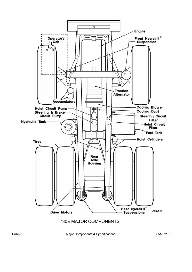
FAM2-2 Major Components & Specifications FAM0210
730E MAJOR COMPONENTS

8/17/2019 Ce Aw 004101
http://slidepdf.com/reader/full/ce-aw-004101 19/265
FAM0210 Major Components & Specifications FAM2-3
SPECIFICATIONS
These specifications are for the standard 730E dump truck. Customer options may change this listing.
ENGINE
Komatsu SSA16V159
Number of Cylinders . . . . . . . . . . . . . . . . . . . . . . . 16
Operating Cycle. . . . . . . . . . . . . . . . . . . . . . 4-Stroke
Rated Brake HP. . 1491 kW (2000 HP) @ 1900 RPM
Flywheel HP . . . . 1388 kW (1860 HP) @ 1900 RPM
Weight (Wet) . . . . . . . . . . . . . . . 5294 kg (11,670 lbs)
ELECTRIC DRIVE SYSTEM
STATEX III w/Fuelsaver . . . . . . . . . AC/DC Current
Alternator . . . . . . . . . . . . . General Electric GTA - 22
Motorized Wheels . . . . . . . . . . General Electric 788*
Standard Gear Ratio* . . . . . . . . . . . . . . . . . 26.825:1
Maximum Speed . . . . . . . . . . . 34.6 mph (55.7 km/h)
*NOTE: Wheel motor application depends upon GVW, haul road
grade, haul road length, rolling resistance, and other parameters.
KOMATSU & G.E. must analyze each job condition to assure
proper application.
DYNAMIC RETARDING
Electric Dynamic Retarding . . . . . . . . . . . . Standard
Maximum Retarding . . . . . . . . . 2759 kW (3700 HP)
. . . . . . . . . . . . . With Continuous Rated Blown Grids
. .Two-Speed Overspeed & Extended Range Retard-
ing
. . . . . . . . . . . . . . . . . . . . . . . . . . . Reverse Retarding
BATTERY ELECTRIC SYSTEM
Batteries . Bumper-Mounted in Polyethylene Boxes
. . . . . . . . . . Four 12-Volt Batteries in Series/Parallel
. . . . . . . . . . . . . . . . . . . . 220 Ampere-Hour Capacity
. . . . . . . . . . . . . . . . . . . . . . . With Disconnect Switch
Alternator . . . . . . . . . . . 24-Volt, 220 Ampere Output
Lighting . . . . . . . . . . . . . . . . . . . . . . . . . . . . . 24-Volt
Starters (2). . . . . . . . . . . . . . . . . . . . . . . . . . . 24-Volt
SERVICE CAPACITIES
Liters . . . U.S. Gallons
Crankcase (includes lube oil filters)
Komatsu . . . . . . . . . . . . . . . . . 223. . . . . . . . . . . . .59
Cooling System . . . . . . . . . . . 409. . . . . . . . . . . .108
Fuel . . . . . . . . . . . . . . . . . . . 3217 . . . . . . . . . . .850
Hydraulic System . . . . . . . . . . 731 . . . . . . . . . . .193
Wheel Motor Gear Box. . . .40/Wheel . . .10.5/Whee
HYDRAULIC SYSTEM
Pumps:
Hoist (gear-type). . . . . . . . . . .513 l/min (135.6 GPM
. . . . . . . . . . . . at 17240 kPa (2500 psi) @ 1900 rpm
Steering/Brake (vane-type). . . . . 235 l/min (62 GPM
. . . . . . . . . . . at 18960 kPa (2750 psi) @ 1900 RPM
Relief Pressure-Hoist . . . . . . . .17240 kPa (2500 psi
Relief Pressure-Steering . . . . .27580 kPa (4000 psi
Hoist . . . . . . . . Two Three-Stage Hydraulic Cylinders
Tank . . . . . . . Vertical - Cylindrical, Non-Pressurized
Service Capacity . . . . . . . . 731 Liters (193 U.S. Gal
Filtration . . . . . . . . . . . In-line Replaceable Elements
Suction . . . . . . . . . . . . . Single, Full Flow, 100 Mesh
Hoist and Steering High-Pressure Filters
. . . . . . . . . . . . . . . . . Dual, Full Flow, Seven Micron
. . . . . . . . . . . . . . . . . . . . . . . . . Beta 12 rating = 200
SERVICE BRAKES
Actuation . . . . . . . All Hydraulic - Caliper/Disc
. . . . . . . . . . . . . . . (Front) . . . . . . . . . . . . . . . .(Rear
Type . . . . . . . . .Single Disc. . . . . . . . . . . . Dual Disc
. . . . . . . . . . . . Wheel Speed. . . . . .Armature Speed
STEERING
Turning Circle (SAE). . . . . . . . . . . . . . . 28.0 m (92 ft
Twin hydraulic cylinders with accumulator assist toprovide constant rate steering.
Emergency power steering automatically provided by
accumulators (meets SAE J1511).

8/17/2019 Ce Aw 004101
http://slidepdf.com/reader/full/ce-aw-004101 20/265
FAM2-4 Major Components & Specifications FAM0210
These specifications are for the 730E dump truck without trolley assist. Specifications for trolley trucks will be dif-
ferent.
STANDARD DUMP BODY*
Capacity:
Struck . . . . . . . . . . . . . . . . 77 m³ . . . . . 101 yds³
Heaped @ 2:1 (SAE) . . . . 111 m³ . . . . 145 yds³
Width (inside) . . . . . . . . . . . . . . . 5.61 m (22 ft 6 in.)
Depth . . . . . . . . . . . . . . . . . . . . . 2.08 m (6 ft 10 in.)
Loading Height . . . . . . . . . . . . . . 5.61 m (18 ft 5 in.)
Dumping Angle. . . . . . . . . . . . . . . . . . . . . . . . . . 45°
*Optional capacity dump bodies are available.
TIRES
Radial Tires (standard) . . . . . . . . . . . . . . 37.00 R57
Rock Service, Deep Tread . . . . . . . . . . . . Tubeless
Rims . (Patented Phase II New Generation™ Rims)
Tires and Rims . . . . . . . . . . . . . . . Interchangeable
WEIGHT DISTRIBUTION
Empty Vehicle Kilog rams (Pounds)
Front Axle . . . . . . . . . . . . 66,840 . . . . (147,357)
Rear Axle . . . . . . . . . . . .73,752 . . . . . . .(162,593)
Total (100% fuel) . . . . . .140,592. . . . . . . (309,950)
Standard Komatsu Body .25,612. . . . . . . .(61,000)
Standard Tire Weight. . . . 18,371. . . . . . . .(40,500)
Loaded Vehicle Kilograms . . . (Pounds)
Front Axle . . . . . . . . . . 107,026. . . . . . . 235,950)
Rear Axle. . . . . . . . . . . . 217,296. . . . . . . 479,050)
Total * . . . . . . . . . . . . . 324,322 . . . . . .(715,000)
Nominal Payload . . . . . 183,730. . . . . . . (405,050)
*Nominal payload is defined by Komatsu America
Corporation’s payload policy documentation. In gen-
eral, the nominal payload must be adjusted for the
specific vehicle configuration and site application.The figures above are provided for basic product
description purposes. Please contact your Komatsu
distributor for specific application requirements.

8/17/2019 Ce Aw 004101
http://slidepdf.com/reader/full/ce-aw-004101 21/265
FAM0310 Major Component Weights Page 3-1
MAJOR COMPONENT WEIGHTS
The condition of lifti ng slings, chains, and/or cables used for lifting components must be inspected before
each use. Lifting equipment must be in good condition and rated for approximately two times the weight
being lif ted. DO NOT use worn o r damaged lifting equipment. Serious in jury and damage may result.
Optional equipment added onto the truck may cause an increase to the component weights listed in this
chapter. Contact your customer support manager for concerns or questions about lifting truck compo-
nents.
NOTE: All component weights are dry weights. The additional weight of coolant, fuel, and oil that may be in the
components are not calculated into this list.
ITEM KILOGRAMS POUNDS
CHASSIS
Chassis . . . . . . . . . . . . . . . . . . . . . . . . . . . . . . . . . . . . . . . . . . . . . . . . . . . 38,555 . . . . . . . . . . . . . . . . . . . . . 85,000
Wheel Rim. . . . . . . . . . . . . . . . . . . . . . . . . . . . . . . . . . . . . . . . . . . . . . . . . .2,586 . . . . . . . . . . . . . . . . . . . . . . 5,700
Tire . . . . . . . . . . . . . . . . . . . . . . . . . . . . . . . . . . . . . . . . . . . . . . . . . . . . . . .2,404 . . . . . . . . . . . . . . . . . . . . . . 5,300
Rim & Tire.. . . . . . . . . . . . . . . . . . . . . . . . . . . . . . . . . . . . . . . . . . . . . . . . . .4,990 . . . . . . . . . . . . . . . . . . . . . 11,000
DECK AND DECK SUPPORT COMPONENTS
Cab . . . . . . . . . . . . . . . . . . . . . . . . . . . . . . . . . . . . . . . . . . . . . . . . . . . . . . .2,449 . . . . . . . . . . . . . . . . . . . . . . 5,400
RH Deck . . . . . . . . . . . . . . . . . . . . . . . . . . . . . . . . . . . . . . . . . . . . . . . . . . . . 724 . . . . . . . . . . . . . . . . . . . . . . 1,596
LH Deck . . . . . . . . . . . . . . . . . . . . . . . . . . . . . . . . . . . . . . . . . . . . . . . . . . . . 635 . . . . . . . . . . . . . . . . . . . . . . 1,400
Center Deck . . . . . . . . . . . . . . . . . . . . . . . . . . . . . . . . . . . . . . . . . . . . . . . . . 233 . . . . . . . . . . . . . . . . . . . . . . . .514
Left Deck Support . . . . . . . . . . . . . . . . . . . . . . . . . . . . . . . . . . . . . . . . . . . . . 408 . . . . . . . . . . . . . . . . . . . . . . . .900
Right Deck Support . . . . . . . . . . . . . . . . . . . . . . . . . . . . . . . . . . . . . . . . . . . 295 . . . . . . . . . . . . . . . . . . . . . . . .650
LH Upright . . . . . . . . . . . . . . . . . . . . . . . . . . . . . . . . . . . . . . . . . . . . . . . . . . 771 . . . . . . . . . . . . . . . . . . . . . . 1,700
RH Upright . . . . . . . . . . . . . . . . . . . . . . . . . . . . . . . . . . . . . . . . . . . . . . . . . . 907 . . . . . . . . . . . . . . . . . . . . . . 2,000
LH Diagonal Beam (ROPS) . . . . . . . . . . . . . . . . . . . . . . . . . . . . . . . . . . . . . . 98 . . . . . . . . . . . . . . . . . . . . . . . .216
Diagonal Ladder . . . . . . . . . . . . . . . . . . . . . . . . . . . . . . . . . . . . . . . . . . . . . . 130 . . . . . . . . . . . . . . . . . . . . . . . .287

8/17/2019 Ce Aw 004101
http://slidepdf.com/reader/full/ce-aw-004101 22/265
Page 3-2 Major Component Weights FAM0310
ITEM KILOGRAMS POUNDS
DRIVE SYSTEM
Air Intake Duct . . . . . . . . . . . . . . . . . . . . . . . . . . . . . . . . . . . . . . . . . . . . . . . .214 . . . . . . . . . . . . . . . . . . . . . . . . 472
Retard Grid Assembly . . . . . . . . . . . . . . . . . . . . . . . . . . . . . . . . . . . . . . . . 3,833 . . . . . . . . . . . . . . . . . . . . . . .8,450
Electrical Control Cabinet . . . . . . . . . . . . . . . . . . . . . . . . . . . . . . . . . . . . . 1,678 . . . . . . . . . . . . . . . . . . . . . . .3,700
Wheel Motor & Service Brake Assembly . . . . . . . . . . . . . . . . . . . . . . . . . 10,569 . . . . . . . . . . . . . . . . . . . . . .23,300
FLUID COMPONENTS
Hoist Cylinder . . . . . . . . . . . . . . . . . . . . . . . . . . . . . . . . . . . . . . . . . . . . . . . . .698 . . . . . . . . . . . . . . . . . . . . . . .1,539
Hydraulic Tank . . . . . . . . . . . . . . . . . . . . . . . . . . . . . . . . . . . . . . . . . . . . . . . .361 . . . . . . . . . . . . . . . . . . . . . . . . 796
Fuel Tank . . . . . . . . . . . . . . . . . . . . . . . . . . . . . . . . . . . . . . . . . . . . . . . . . . 1,270 . . . . . . . . . . . . . . . . . . . . . . .2,800
FRONT AXLE COMPONENTS
Spindle And Brake Assembly . . . . . . . . . . . . . . . . . . . . . . . . . . . . . . . . . . . 3,330 . . . . . . . . . . . . . . . . . . . . . . .7,340
Steering Arm . . . . . . . . . . . . . . . . . . . . . . . . . . . . . . . . . . . . . . . . . . . . . . . . .192 . . . . . . . . . . . . . . . . . . . . . . . . 423
Front Suspension Cylinder . . . . . . . . . . . . . . . . . . . . . . . . . . . . . . . . . . . . . 1,964 . . . . . . . . . . . . . . . . . . . . . . .4,330
Tie Rod. . . . . . . . . . . . . . . . . . . . . . . . . . . . . . . . . . . . . . . . . . . . . . . . . . . . . .136 . . . . . . . . . . . . . . . . . . . . . . . . 300

8/17/2019 Ce Aw 004101
http://slidepdf.com/reader/full/ce-aw-004101 23/265
FAM0406 Field Welding For Assembly Or Repair 4-1
FIELD WELDING FOR ASSEMBLY OR REPAIR
When welding on Komatsu equipment, whether at
initial field assembly or during normal maintenance
repairs, special procedures must be followed.
Due to the continuous program of research and
development, periodic revisions may be made to this
publication. It is recommended that customers con-
tact their distributors for information on the latest revi-
sion.
The welding information contained in this chapter is
general information that must be followed unless oth-
erwise specified in a detailed repair procedure pro-
vided on an engineering drawing or a detailed
specific repair procedure. Additional specific informa-
tion, or detailed instructions can be obtained through
your local Komatsu customer support manager.
WELDER QUALIFICATION ANDTRAINING
The welding technique must be of the highest stan-
dard to produce the soundest weld possible. Only
welders who have been trained and qualified for
structural steel welding in all positions, in conform-
ance with the American Welding Society (AWS) D1.1
or (AWS) D14.3 only, are allowed to perform the
welding. The welding instructions for field assembly
of Komatsu components are normally provided by
engineering drawings. Additional detailed welding
instructions for field repairs are provided in the field
repair manual SEB14001. A full understanding of the
AWS standard welding symbols is necessary to per-
form and inspect such field welds. Weld sizes speci-
fied on the drawings are intended to reflect minimum
requirements.
WELD PROCEDURES
Electric arc welding, either the semi-automatic “MIG
(GMAW), Flux Core (FCAW), or “Stick” electrode
welding (SMAW), are approved processes for field
installation and maintenance welding. Welding o
highly stressed structural members such as castingstorque tubes, top and bottom plates on the frame
rails, and the curved intersection points of frames
should be done with the specific detailed instructions
from Komatsu Product Service. See Annex A fo
repair procedures. These repair procedures are
detailed instructions for most high stressed structura
members.
APPROVED CONSUMABLES
GMAW - LW102-15 or ER80S-D2
FCAW - E70T-5, E71T-8, or E71T8-NI1
SMAW - E7018-1, E8018-C1, or E8018-C3
WELD QUALITY REQUIREMENTS
1. Each weld must be homogeneous with low
porosity, free from cracks, and slag inclusions.
2. Each weld must have complete fusion between
the base metal and weld metal added by the
electrode.
3. All welds must be reasonably smooth, withouexcessive deformity, and all craters filled. No
cracks are permitted.
4. The toe of a weld to a stressed member mus
have a smooth transition. Excessive convexity
in multi-pass fillet welds is not permitted. Exces-
sive convexity produces high residual stress in
the throat of the weld, and is not permitted.
5. Undercut in excess of 0.8 mm (0.03 in.) on criti-
cal welds must be reworked by the application
of welding an additional cover pass. It is impor-
tant that this pass is blended with the existing
weld.
8/17/2019 Ce Aw 004101
http://slidepdf.com/reader/full/ce-aw-004101 24/265
4-2 Field Welding For Assembly Or Repair FAM0406
6. When welding in the vertical position, always
weld using the vertical up technique. Large
wash weld weaves should not be used when
welding on truck frames. Properly applied multi-
ple pass welding is the required procedure on
truck frames.
7. Slag is to be removed from all weld beads, and
must be completely removed before each pass
in a multiple pass procedure. It is also requiredthat all slag is removed and tie in all areas.
Grind all welds where a weld crosses or inter-
sects with another weld.
MATERIALS, CONTROLS, ANDPRECAUTIONS
The steel used in the fabrication of all Komatsu
equipment is of high strength low alloy (HSLA) mate-
rial of different grades. The standard dump body
main plates are made from abrasion resistant materi-
als. These materials offer themselves very well to
welding during fabrication, and repair.
The welding consumables are often supplied by
Komatsu America Corp. with the new equipment as
part of the field welding / assembly package. For field
welding and repairs, the approved consumables as
detailed, should be procured from a local, reliable
supplier. Other highly specialized welding consum-
ables are available but have limited use on Komatsu
structural components. Approval is required from
your Komatsu customer support manager.
Control of the welding area environment is essential
for producing proper and sound welds. Essentially,
five areas require attention and control.
1. Air Movement - Avoid areas where air move-
ment from wind, drafts, or blowers is prevalent.
This is particularly important when a shielding
gas is being used as part of the welding pro-
cess.
2. Low Ambient Temperature - DO NOT weld in
temperatures below 50°F (10°C). At low tem-
perature conditions, preheating of all welding
joint work areas is required. See preheat and
post heating requirements as detailed in Annex
A.
3. Weld Cooling - Protect the weld area from a
rapid cooling rate. Heat retardation may be
accomplished through the use of heat lamps,torches, insulating blankets, etc.
4. Moisture - Any moisture on the steel surfaces to
be welded must be removed before welding.
Electrodes must be stored in sealed containers
until needed. Electrodes must be kept in a
warming oven at the work location until used to
prevent any moisture absorption which might
affect weld quality.
5. Foreign Materials - Any foreign substances
(dirt, paint, rust, scale, and carbon deposits
from cuttings) must be removed prior to weld-
ing. Clean all weld areas and surfaces with agrinder to ensure that all foreign materials have
been removed.
WELD INSPECTION
All welding repairs are subject to inspection by a
Komatsu appointed inspector or laboratory to insure
quality. After the weld has been made it can be
inspected by a number of non-destructive evaluation
techniques. The inspections can include any of the
methods listed below. All assembly welds and weld
repairs that are deemed unacceptable by the inspec-
tor must be corrected at no additional cost to
Komatsu. All weld repairs are also subject to addi-
tional inspection.
1. Visual Inspection - This is the process of look-
ing for potential defects such as undersized
welds that can be checked with weld gauges
for, surface cracks, surface porosity, craters,
and undercuts.

8/17/2019 Ce Aw 004101
http://slidepdf.com/reader/full/ce-aw-004101 25/265
FAM0406 Field Welding For Assembly Or Repair 4-3
2. Dye Penetrant Inspection - This is an easily
applied process which indicates cracks or sur-
face conditions. The process is relatively inex-
pensive, but does not produce a permanent
record except by normal photography.
3. Fluorescent Penetrant Inspection - Similar to
dye penetrant inspection. This process uses a
black (ultraviolet) light for increased efficiency
and accuracy.
4. Magnetic Particle Inspection - This process
requires special equipment that is usually more
costly than the dye penetrant inspections. This
process does not provide a permanent record
except by normal photography.
5. Ultrasonic Inspection - This is a popular method
of examining weld discontinuities. Specialized
equipment and operator certification is required.
With some equipment printed data is available
of the test providing a permanent record. Also,
operator records with equipment settings andtest results are normally recorded.
6. X-Ray Inspection - This process provides a
view of the weld and base materials but it is
highly specialized. This procedure provides a
permanent visual record, but is more expensive
than most other inspection techniques.
RECORDS
Komatsu requires record keeping of all welding work
This information is valuable when personnel or job
conditions change. The service and warranty depart
ments of Komatsu must be provided with inspection
reports and photographs of the weld area before
during, and after the repair. The photographs must
be clear and close enough to show the weld joinpreparation complete, with backer bars installed, etc
just prior to welding. These photos easily identify i
the required preheating and post heating have been
done with a three inch circumference around the
weld repair area. Without this documentation
Komatsu will not cover any weld repair claim made
under warranty. No exceptions will be made.
ANNEX A
The following are general repair procedures, which
must be followed for all repair and rework of major
load carrying members on Komatsu equipment.
1. The repair or rework area must be protected
from wind and moisture during the entire proce-
dure. If the repair work is to done outside addi-
tional precautions must be taken to protect the
weld repair process from outside elements. Al
welding should be done at an ambient tempera
ture of 10°C (50°F) or above.
2. Clean and grind the entire repair area toremove all rust, grease, oils, paint, and any
other foreign materials likely to contaminate the
weld.

8/17/2019 Ce Aw 004101
http://slidepdf.com/reader/full/ce-aw-004101 26/265
4-4 Field Welding For Assembly Or Repair FAM0406
3. Air arc the entire crack leaving a V-shape joint.
The depth of the V (or U shaped) joint will be
determined by the depth of the crack. The width
to depth ratio should be approximately 1.25:1
and never less than 1:1. All cracks through the
parent material will require a slightly wider root
opening than the original, usually 6 mm (0.25
in.) to allow the installation of a backup strip.
Backup strips are required for all cracks thathave gone through the parent material and can-
not be welded from both sides. If a weld repair
allows access to both sides of the plate, no
backup strip is required as long as complete
weld penetration is achieved. If backup strips
are not used, the surface profile on both sides
must be ground smooth with no undercut. Doc-
umentation must support this repair. Photo-
graphs of surface condition are required by the
service and warranty departments of Komatsu.
4. Use dye penetrant to ensure the cracks are
completely removed.5. After air arcing and inspections (Steps 3 & 4) all
areas cut by the air arc should be cleaned thor-
oughly with a grinder to remove all possible car-
bon deposits and dye penetrant.
6. Fill gouges with weld and grind all surfaces
smooth to avoid defects in the new weld.
7. Grind all surfaces to be welded so they are free
of slag, rust, and any other foreign materials.
8. Preheat the entire weld joint area until the sur-
rounding surface area reaches 150°C (300°F)
at a distance of 76 mm (3 in.) from all areas to
be welded.
9. All welds are to be made with approved con-
sumables only. The SMAW (Stick) welding rod
must be used within four hours after being
removed from a new sealed container or from a
52°C (125°F) minimum drying oven. Any rod
that exceeds this exposure time must be dried
for one hour at 427°C (800°F) before being
used. Keep all weld starts and stops to a mini-
mum.
10. When the weld is complete, immediately (before
the weldment cools) post heat the entire weld
area to 150°C (300°F). Even if the area is over
150°C (300°F) heat must be applied to maintain
this temperature for 15 minutes, and then allow
it to cool slowly. In some cases this might
require wrapping with insulation blankets.
11. Grind all butt-welded repairs smooth using 36 or
finer grit grinding material. All grinding marks
should be parallel to the direction of primary
stress if possible (and if known).
12. Hammer peen the toes of repair fillet welds as
detailed in Annex B, see attached.
13. Inspect repaired areas (for surface defects)
using magnetic particle or dye penetrant
inspection procedures.
14. If surface defects are found, remove all defects
by grinding to a maximum depth of 1.5 mm
(0.06 in.). Larger defects must be removed as
per the above mentioned procedures. All spot
welding also requires preheating and post heat-
ing.
8/17/2019 Ce Aw 004101
http://slidepdf.com/reader/full/ce-aw-004101 27/265
FAM0406 Field Welding For Assembly Or Repair 4-5
ANNEX B
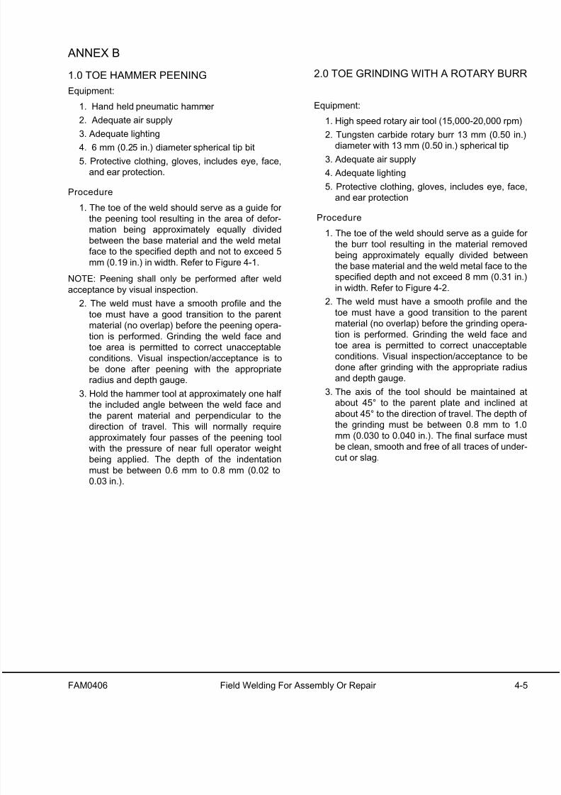
1.0 TOE HAMMER PEENING
Equipment:
1. Hand held pneumatic hammer
2. Adequate air supply
3. Adequate lighting
4. 6 mm (0.25 in.) diameter spherical tip bit
5. Protective clothing, gloves, includes eye, face,
and ear protection.
Procedure
1. The toe of the weld should serve as a guide for
the peening tool resulting in the area of defor-
mation being approximately equally divided
between the base material and the weld metal
face to the specified depth and not to exceed 5
mm (0.19 in.) in width. Refer to Figure 4-1.
NOTE: Peening shall only be performed after weldacceptance by visual inspection.
2. The weld must have a smooth profile and the
toe must have a good transition to the parent
material (no overlap) before the peening opera-
tion is performed. Grinding the weld face and
toe area is permitted to correct unacceptable
conditions. Visual inspection/acceptance is to
be done after peening with the appropriate
radius and depth gauge.
3. Hold the hammer tool at approximately one half
the included angle between the weld face and
the parent material and perpendicular to thedirection of travel. This will normally require
approximately four passes of the peening tool
with the pressure of near full operator weight
being applied. The depth of the indentation
must be between 0.6 mm to 0.8 mm (0.02 to
0.03 in.).
2.0 TOE GRINDING WITH A ROTARY BURR
Equipment:
1. High speed rotary air tool (15,000-20,000 rpm)
2. Tungsten carbide rotary burr 13 mm (0.50 in.)diameter with 13 mm (0.50 in.) spherical tip
3. Adequate air supply
4. Adequate lighting
5. Protective clothing, gloves, includes eye, face
and ear protection
Procedure
1. The toe of the weld should serve as a guide fo
the burr tool resulting in the material removed
being approximately equally divided between
the base material and the weld metal face to the
specified depth and not exceed 8 mm (0.31 in.)in width. Refer to Figure 4-2.
2. The weld must have a smooth profile and the
toe must have a good transition to the paren
material (no overlap) before the grinding opera-
tion is performed. Grinding the weld face and
toe area is permitted to correct unacceptable
conditions. Visual inspection/acceptance to be
done after grinding with the appropriate radius
and depth gauge.
3. The axis of the tool should be maintained a
about 45° to the parent plate and inclined a
about 45° to the direction of travel. The depth ofthe grinding must be between 0.8 mm to 1.0
mm (0.030 to 0.040 in.). The final surface mus
be clean, smooth and free of all traces of under
cut or slag.

8/17/2019 Ce Aw 004101
http://slidepdf.com/reader/full/ce-aw-004101 28/265
4-6 Field Welding For Assembly Or Repair FAM0406
FIGURE 4-1. TOE HAMMER PEENING

8/17/2019 Ce Aw 004101
http://slidepdf.com/reader/full/ce-aw-004101 29/265
FAM0406 Field Welding For Assembly Or Repair 4-7
FIGURE 4-2. TOE GRINDING WITH A ROTARY BURR

8/17/2019 Ce Aw 004101
http://slidepdf.com/reader/full/ce-aw-004101 30/265
4-8 Field Welding For Assembly Or Repair FAM0406
BIBLIOGRAPHY
American Welding Society Bulletin No. D14.3-94/
D1.1 - Specification for Welding Earthmoving and
Construction Equipment
Metals and How to Weld Them - James F. Lincoln
Arc Welding Foundation. Cleveland, Ohio
Procedure Handbook of Arc Welding - Lincoln Elec-tric Company, Cleveland, Ohio
American Welding Society - Welding Handbook
British Standard BS5135 - Metal Arc Welding of Car-
bon and Carbon-Manganese Steels
Welding Steels Without Hydrogen Cracking - The
Welding Institute, F. R. Coe, Author
SPECIAL PRECAUTIONS WHENSERVICING AN A/C DRIVE SYSTEMTRUCK
Consult a qualified technician, specifically trained for
servicing the A/C drive system, before welding on the
truck.
The following procedures must be followed to ensurethe safety of maintenance personnel and to help pre-
vent damage to the equipment.
Anyt ime the engine is on:
• Do not open any of the cabinet doors or
remove any covers.
• Do not use power cables for hand holds or
foot steps.
• Do not touch retarder grid elements.
Before opening any cabinets or touching a grid
element or a power cable, the engine and all
warning lights must be off.
Engine Stop Procedure Prior To Maintenance
Perform the following procedure prior to maintenance
to ensure that no hazardous voltages are present in
the A/C drive system.
1. Before turning off the engine, verify the status
of all the drive system warning lights on the
overhead display panel. Use the lamp test
switch to verify that all lamps are functioning
properly.
2. If all red drive system warning lights are off,
turn the engine off.
3. After the engine has been off for at least five
minutes, inspect the link voltage lights. The
lights are located on the exterior of the main
control cabinet and back wall of the operator's
cab (DID panel). If all lights are off, the retard-ing grids, wheel motors, alternator, and power
cables connecting these devices are safe to
work on.

8/17/2019 Ce Aw 004101
http://slidepdf.com/reader/full/ce-aw-004101 31/265
FAM0406 Field Welding For Assembly Or Repair 4-9
Locate the GF cut-out switch in the access
panel on the left side of the main control cabi-
net. Place the switch in the CUTOUT position.
This will prevent the alternator from re-energiz-
ing and creating system voltage until the switch
is returned to its former position.
After repairs, replace all covers and doors andplace the GF cutout switch and battery discon-
nect switches in their original positions. Recon-
nect all harnesses prior to starting the truck.
Leave the drive system in the rest mode until
the truck is to be moved.
4. If the red lights on the exterior of the control
cabinet and/or the back wall of the operator's
cab continue to be illuminated, a fault has
occurred.
Leave all cabinet doors in place. DO NOT touch
the retard grid elements. DO NOT disconnectany power cables or use them as hand or foot
holds.
Notify your Komatsu customer service manager
immediately. Only qualified personnel, specifi-
cally trained for servicing the A/C drive system,
may perform this service.
General Welding Guidelines
1. Open the battery disconnect switches and dis
connect the battery charging alternator lead
wire.
2. Disconnect all electrical harnesses from the
Engine Control System (ECS). The ECS is
located inside the electrical cabinet behind the
operator's cab. Disconnect the ground strapfrom the ECS.
3. Fasten the welding machine ground (-) lead to
the piece being welded. The grounding clamp
must be attached as near as possible to the
weld area.
4. DO NOT weld on the rear of the control cabinet
The metal panels on the back of the cabinet are
part of the capacitors and cannot be heated.
5. DO NOT weld on the retard grid exhaust lou-
vers.
6. Some power cable panels throughout the truck
are made of aluminum or stainless steel. Theymust be repaired with the same material or the
power cables may be damaged.
7. Power cables must be cleated in wood or othe
non-ferrous materials. DO NOT repair cable
cleats by encircling the power cables with meta
clamps or hardware. Inspect power cable insu-
lation prior to servicing the cables and prior to
returning the truck to service. Discard cables
with broken insulation.
8. Protect power cables and wiring harnesses
from weld spatter and heat.
9. DO NOT lay welding cables over or near thevehicle electrical harnesses. Welding voltage
may be induced into the electrical harnesses
and cause damage to components.
10. DO NOT allow welding current to pass through
ball bearings, roller bearings, suspensions, o
hydraulic cylinders.

8/17/2019 Ce Aw 004101
http://slidepdf.com/reader/full/ce-aw-004101 32/265
4-10 Field Welding For Assembly Or Repair FAM0406
NOTES

8/17/2019 Ce Aw 004101
http://slidepdf.com/reader/full/ce-aw-004101 33/265
FAM0506 Receiving & Assembly Preparation Page 5-1
RECEIVING & ASSEMBLY PREPARATION
1. Inspect all components for possible shipping
damages. Note any damage found and report to
shipping agent.
2. Spread out all parts and organize per unit num-
ber. Check for missing parts. List the unit num-ber of all major components. Verify the cab and
decks are with the correct chassis.
3. Install support blocks under the chassis. The
support blocks must be approximately 84 cm
(33 in.) high.
4. Install support blocks under the rear axle hous-
ing. The support blocks must be approximately
30 cm (12 in.) high and spread out along the
axle. The support blocks must be a minimum of
51 mm (2 in.) away from the wheel motor
mounting face.
5. Clean all mounting surfaces on the chassis and
on the individual components.
6. Check all electrical connectors and verify they
are free of paint and/or corrosion. Clean any
connector with questionable electrical continu-
ity.
7. Check all factory installed components for the
proper tightening torque.
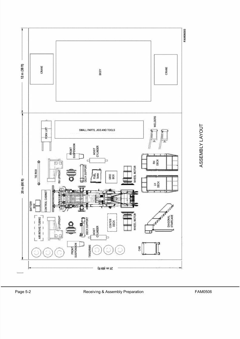
8. Arrange the work site as shown on the following
page.
8/17/2019 Ce Aw 004101
http://slidepdf.com/reader/full/ce-aw-004101 34/265
Page 5-2 Receiving & Assembly Preparation FAM0506
A S S E M B L Y L A Y O U T

8/17/2019 Ce Aw 004101
http://slidepdf.com/reader/full/ce-aw-004101 35/265
FAM0610 10/07 Chassis Assembly Page 6-1
CHASSIS ASSEMBLY
Due to differences in machine configurations and
shipping restrictions/requirements throughout the
world, the shipping and packaging of large machines
varies. Photographs or illustrations used in the fol-
lowing procedures are provided as general guide-
lines only. Actual assembly may be different, but this
general procedure provides a basic outline for assembly.
Items like the hydraulic tank and the accumulators
may have been removed for shipping and will have to
be locally installed.
Each shipment may be different, depending on the
truck configuration and destination.
RECOMMENDED ASSEMBLY DATA
1. Service Report (Pre-Delivery)
2. Acknowledgement of Receipt of Company War-
ranty
3. Assembly Blueprints & Schematics
4. Fluid Specifications (refer to the lubrication
chart in Section 10, Appendix)
5. Suspension Oiling & Charging Procedure
(available in Section 10, Appendix)
6. Fan Drive Adjustment Procedure (available in
the engine service manual)
7. Toe-In Adjustment Procedure (Section 10,
Appendix)
8. Hydraulic Checkout Procedure (Section 10,
Appendix)
9. Brake Checkout Procedure (Section 10, Appen-
dix)
10. Propulsion System Checkout Procedure (avail-
able in Section 10 of this manual)
11. Filter List (available in parts book)
12. Lubrication & Service PM Forms (available in
the operation and maintenance manual)
13. Component Weights - for crane reference
(available in Section 3 of this manual)
14. Standard Torque Chart (available in Section 10
of this manual)
15. Field Assembly Inspection Report Form (avail-
able in Section 10 of this manual)
BASIC ASSEMBLY PROCEDURE
1. Site preparation
2. Unload truck components
3. Assemble the chassis4. Weld the body
NOTE: Chassis assembly and body welding may be
done in either order, or simultaneously. The most
logical order depends on available resources such as
cranes, welders, assemblers, etc.
5. Static checkout (electrical & mechanical)
6. Install the body
7. Dynamic checkout (electrical & mechanical)
8. Site cleanup
8/17/2019 Ce Aw 004101
http://slidepdf.com/reader/full/ce-aw-004101 36/265
Page 6-2 Chassis Assembly 10/07 FAM0610
CHASSIS ASSEMBLY
The photographs referenced in this procedure depict
an actual truck assembly. Assembly at other loca-
tions may be different. However, this outline will pro-
vide a general basis for assembly.
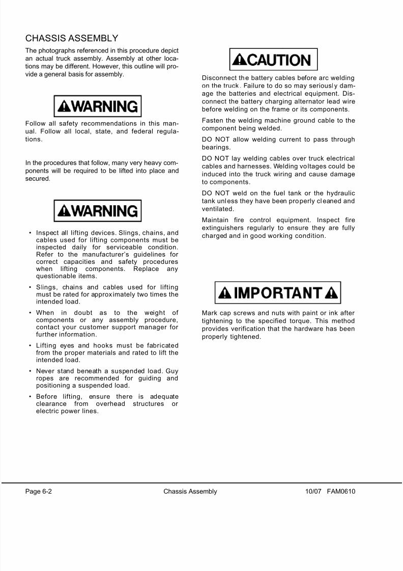
Follow all safety recommendations in this man-
ual. Follow all local, state, and federal regula-
tions.
In the procedures that follow, many very heavy com-
ponents will be required to be lifted into place and
secured.
• Inspect all lifting devices. Slings, chains, andcables used for lifting components must beinspected daily for serviceable condition.Refer to the manufacturer’s guidelines for correct capacities and safety procedureswhen lifting components. Replace anyquestionable items.
• Slings, chains and cables used for liftingmust be rated for approx imately two times the
intended load.
• When in doubt as to the weight of components or any assembly procedure,contact your customer support manager for further information.
• Lifting eyes and hooks must be fabricatedfrom the proper materials and rated to lift theintended load.
• Never stand beneath a suspended load. Guyropes are recommended for guiding andpositioning a suspended load.
• Before lifting, ensure there is adequateclearance from overhead structures or electric power lines.
Disconnect the battery cables before arc welding
on the truck . Failure to do so may seriously dam-
age the batteries and electrical equipment. Dis-
connect the battery charging alternator lead wirebefore welding on the frame or its components.
Fasten the welding machine ground cable to the
component being welded.
DO NOT allow welding current to pass through
bearings.
DO NOT lay welding cables over truck electrical
cables and harnesses. Welding vo ltages could be
induced into the truck wiring and cause damage
to components.
DO NOT weld on the fuel tank or the hydraulic
tank unless they have been properly cl eaned andventilated.
Maintain fire control equipment. Inspect fire
extinguishers regularly to ensure they are fully
charged and in good working condition.
Mark cap screws and nuts with paint or ink after
tightening to the specified torque. This method
provides verification that the hardware has been
properly tightened.

8/17/2019 Ce Aw 004101
http://slidepdf.com/reader/full/ce-aw-004101 37/265
FAM0610 10/07 Chassis Assembly Page 6-3
GENERAL PRECAUTIONS ANDINSTRUCTION
1. Clean and remove all foreign material from
component mounting surfaces.
2. DO NOT weld the front uprights until all upper
decks are installed.
3. Torque the deck mounting bolts before the
exhaust tubes, etc. are installed.
4. Verify all electrical connectors are free from
paint and/or corrosion. Clean any connector
that may be questionable.
5. Do not torque the diagonal ROPS beam until
after the operator cab & LH air intake tubes are
in place.
6. Before installing the cab, tap all threaded holes
to remove paint.
7. Verify all wiring is properly connected before
attempting to start the engine.
8. Recheck the torque on hardware installed at the
factory.
9. Use blocks for charging the suspension (oil &
nitrogen). Follow the procedures outlined in
Section 10, Appendix.
10. Use the proper precautions when checking the
nitrogen pressure and oil level in the accumula-tors.
11. Verify the lube system is lubricated, purged and
all levels full prior to start up.
12. Purge air from the steering pump before truck
operation. Pressure will not build in the brake
and steering circuit if air is present. Air in the
system may damage the pump. Refer to the
Hydraulic Checkout Procedure in Section 10 o
this manual.
13. Use the battery disconnect switch when arc
welding. Connect the weld ground near the
weld area.

8/17/2019 Ce Aw 004101
http://slidepdf.com/reader/full/ce-aw-004101 38/265
Page 6-4 Chassis Assembly 10/07 FAM0610
1. Lift the chassis off the truck/trailer or rail car using two cranes with a minimum capacity of 50 tons each. Liftthe chassis onto adequate support blocks or stands. The weight of the chassis, as shipped, is approximately
38,555 kg (85,000 lb).
The support blocks/stands must be approximately 84 cm (33 in.) high at the front, and approximately 30 cm
(12 in.) high under the rear axle housing. Placement of the chassis at this height will allow easy installation of
truck components.
Thoroughly clean the chassis.

8/17/2019 Ce Aw 004101
http://slidepdf.com/reader/full/ce-aw-004101 39/265
FAM0610 10/07 Chassis Assembly Page 6-5
FIGURE 6-1.
FIGURE 6-2.

8/17/2019 Ce Aw 004101
http://slidepdf.com/reader/full/ce-aw-004101 40/265
Page 6-6 Chassis Assembly 10/07 FAM0610
2. Clean the mating surfaces for the deck supports to prepare for installation.

8/17/2019 Ce Aw 004101
http://slidepdf.com/reader/full/ce-aw-004101 41/265
FAM0610 10/07 Chassis Assembly Page 6-7
FIGURE 6-3.
FIGURE 6-4.

8/17/2019 Ce Aw 004101
http://slidepdf.com/reader/full/ce-aw-004101 42/265
Page 6-8 Chassis Assembly 10/07 FAM0610
3. Lift the LH deck support into position. The weight of the deck support is approximately 408 kg (900 lb).
a. Bolt the support into place.
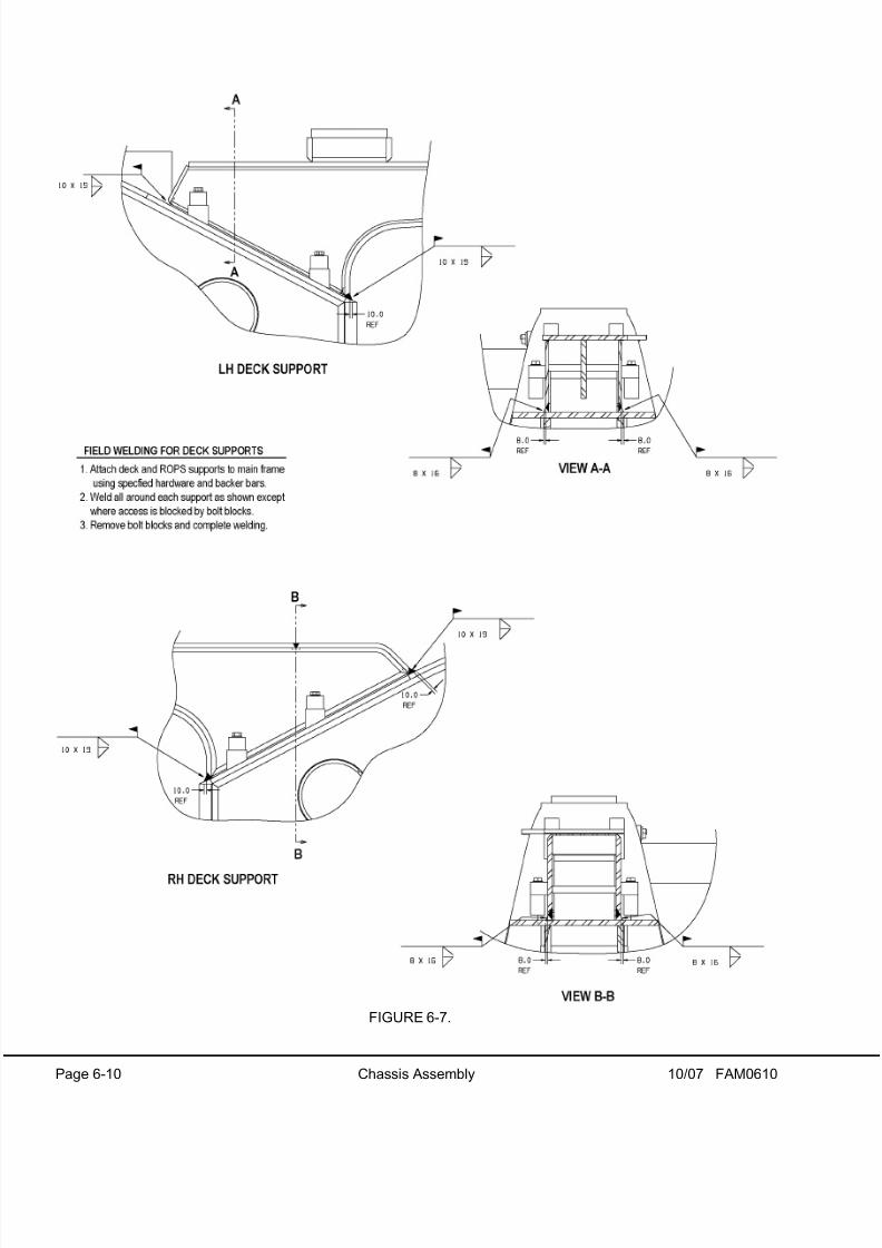
b. Weld the support to the frame. The four tapped pads on each support and the corresponding blocks on the
horsecollar must be removed to allow for a complete weld around the joint. Follow the specifications shown
in Figure 6-7.
c. Grind all areas, and clean. Paint after welding is complete.
If the tapped pads are not removed, a complete weld around the suppor t can not be achieved. Gaps in the
weld around the support may result in premature frame cracking in th is area.
4. Install and weld the RH deck support. The weight of the deck support is approximately 295 kg (650 lb).

8/17/2019 Ce Aw 004101
http://slidepdf.com/reader/full/ce-aw-004101 43/265
FAM0610 10/07 Chassis Assembly Page 6-9
FIGURE 6-5.
FIGURE 6-6.
8/17/2019 Ce Aw 004101
http://slidepdf.com/reader/full/ce-aw-004101 44/265
Page 6-10 Chassis Assembly 10/07 FAM0610
FIGURE 6-7.

8/17/2019 Ce Aw 004101
http://slidepdf.com/reader/full/ce-aw-004101 45/265
FAM0610 10/07 Chassis Assembly Page 6-11
NOTES

8/17/2019 Ce Aw 004101
http://slidepdf.com/reader/full/ce-aw-004101 46/265
Page 6-12 Chassis Assembly 10/07 FAM0610
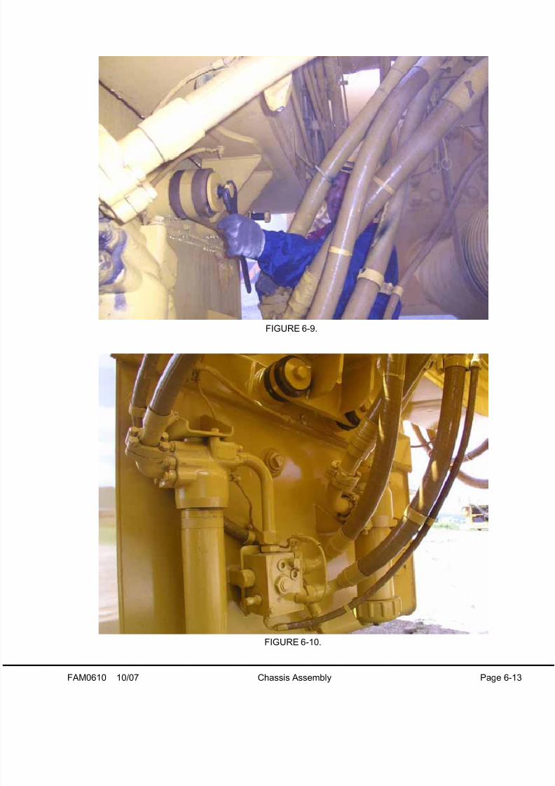
5. Clean the mounting surfaces for the hydraulic tank and the fuel tank.
6. Lift the fuel tank into position on the cradles. The weight of the fuel tank is approximately 1270 kg (2800 lb).
Install the four cap screws and the cradle caps at the top of the tank. Tighten to standard torque. Refer to
Standard Tables in Section 10, Appendix.
Install the rubber dampeners and mounting hardware at the rear of the tank. Tighten the four cap screws to
standard torque.
7. Connect the fuel supply and fuel return hoses to the ports on the fuel tank.
8. Install the filters to the rear of the tank and secure the wiring harness.
FIGURE 6-8.
8/17/2019 Ce Aw 004101
http://slidepdf.com/reader/full/ce-aw-004101 47/265
FAM0610 10/07 Chassis Assembly Page 6-13
FIGURE 6-9.
FIGURE 6-10.

8/17/2019 Ce Aw 004101
http://slidepdf.com/reader/full/ce-aw-004101 48/265
Page 6-14 Chassis Assembly 10/07 FAM0610
9. Clean the mating surfaces for the LH and RH uprights.
10. Attach either upright to a crane using adequate lifting apparatus. Attach a ratchet hoist to the lifting apparatus
to enable the upright to pivot for proper alignment.
11. Lift the LH & RH uprights into position and install the four cap screws for each upright. Tighten to standard
torque. Refer to Standard Tables in Section 10, Appendix.
The weight of the RH upright is approximately 907 kg (2000 lb). The weight of the LH upright is approximately
771 kg (1,700 lb).
DO NOT weld the torque tubes on the uprights until the decks are installed.
12. Attach the upper radiator stabilizers rods to the uprights. After the decks are installed and the uprights welded,
adjust the stabilizers to vertically level the radiator.
FIGURE 6-11.

8/17/2019 Ce Aw 004101
http://slidepdf.com/reader/full/ce-aw-004101 49/265
FAM0610 10/07 Chassis Assembly Page 6-15
FIGURE 6-12.
FIGURE 6-13.

8/17/2019 Ce Aw 004101
http://slidepdf.com/reader/full/ce-aw-004101 50/265
Page 6-16 Chassis Assembly 10/07 FAM0610
FIGURE 6-14.
FIGURE 6-15.

8/17/2019 Ce Aw 004101
http://slidepdf.com/reader/full/ce-aw-004101 51/265
FAM0610 10/07 Chassis Assembly Page 6-17
FIGURE 6-16.
FIGURE 6-17.

8/17/2019 Ce Aw 004101
http://slidepdf.com/reader/full/ce-aw-004101 52/265
Page 6-18 Chassis Assembly 10/07 FAM0610
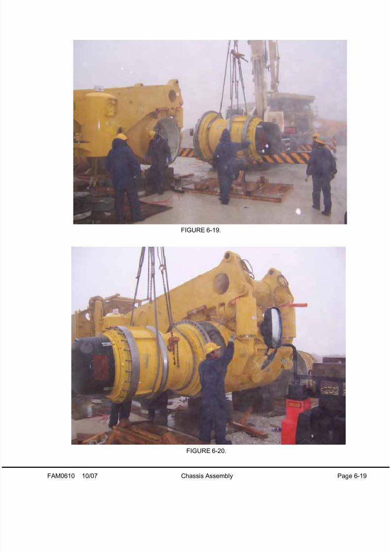
13. Install both wheel motors. The weight of each wheel motor with the service brake and parking brake assem-
blies installed is approximately 10,569 kg (23,300 lb).
The hardened flat washers used in this application are punched during the manufacturing process. Therefore,the washers must be installed with the punched lip away from the head of the mounting cap screws to preventdamage to the fillet between the cap screw head and the shank. Refer to Figure 6-23.
Alternately tighten the wheel motor mounting cap screws to 2007 ± 201 N·m (1480 ± 148 ft lb).
NOTE: When lifting the wheel motors, do not lift under the brake assembly. Shipping fasteners installed in the
outboard rim bolt circle must remain in place during lifting and installation of wheel motors.
FIGURE 6-18.
8/17/2019 Ce Aw 004101
http://slidepdf.com/reader/full/ce-aw-004101 53/265
FAM0610 10/07 Chassis Assembly Page 6-19
FIGURE 6-19.
FIGURE 6-20.

8/17/2019 Ce Aw 004101
http://slidepdf.com/reader/full/ce-aw-004101 54/265
Page 6-20 Chassis Assembly 10/07 FAM0610
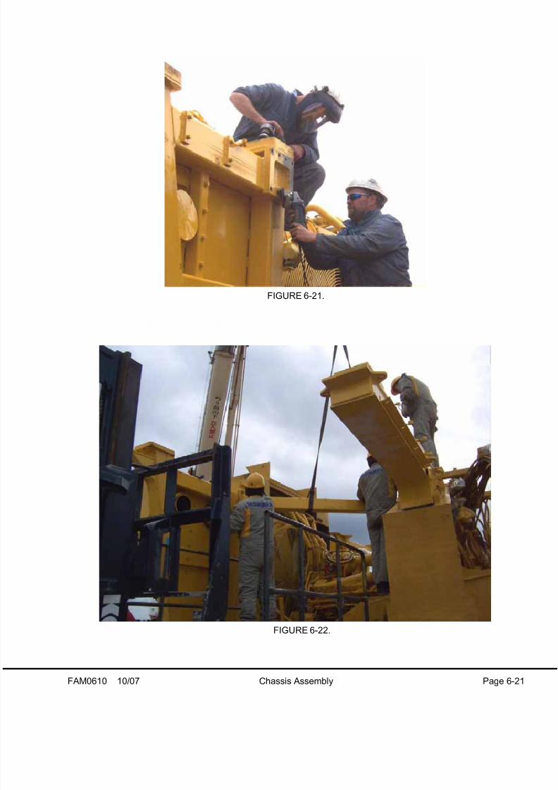
14. Prepare the mounting surfaces for the LH diagonal tube.
Lift the tube into position. The weight of the diagonal tube is approximately 98 kg (216 lb).
Do not tighten the cap screws until the deck and the cab are in place.
8/17/2019 Ce Aw 004101
http://slidepdf.com/reader/full/ce-aw-004101 55/265
FAM0610 10/07 Chassis Assembly Page 6-21
FIGURE 6-21.
FIGURE 6-22.

8/17/2019 Ce Aw 004101
http://slidepdf.com/reader/full/ce-aw-004101 56/265
Page 6-22 Chassis Assembly 10/07 FAM0610
15. Clean and dry the mounting surfaces on both
the suspension and the frame. Use a cleaning
agent that does not leave a film after evapora-
tion, such as trichlorethylene, tetrachlorethyl-
ene, acetone or lacquer thinner.
High tightening torque is required to load the
front suspension mounting cap screws.
Repeated tightening will result in cap screw
fatigue and damage. DO NOT reuse mounting
cap screws, washers and nuts. Replace the
hardware after each use.
Suspension mounting cap screws are specially
hardened to meet or exceed grade 8
specifications. Replace only with cap screws of
correct hardness. Refer to the appropriate parts
book for the correct part numbers..
The use of dry threads in this application is not
recommended. Due to the high tightening forces
required to load these cap screws, dry th reads or
threads lubricated with anti-seize compounds
may result in damage. Only use the approved
lubricants listed below.
• American Anti-Rust Grease #3-X from StandardOil Division of American Oil Company
• Rustolene D grease from Sinclair Oil Company
• Gulf NoRust #3 from Gulf Oil Company
• Rust Ban 326 from Humble Oil Company
• 1973 Rustproof from the Texas Company
• Rust Preventive Grease-Code 312 from theSouthwest Grease and Oil Company
NOTE: If none of the rust preventive greases listed
above are available for field assembly, use one of the
following lubricants:
• SAE 30 weight oil
• 5% Molybdenum - Disulphide Grease
DO NOT use anti-seize compounds.
16. Lubricate the cap screw threads, cap screw
head seats, washer faces, and nut seats with a
rust preventive compound.
17. The hardened flat washers use on the front sus-
pensions are punched during the manufacturing
process. Assemble the cap screws and wash-
ers, and position the punch lip away from the
cap screw head to prevent damage. See Figure
6-23.
18. Lift the front suspension into position. Theweight of each front suspension cylinder is
approximately 2228 kg (4,912 lb). Install the
mounting hardware and tighten according to the
"turn-of-the-nut" method outlined on the follow-
ing pages.
FIGURE 6-23. INSTALLATION OF HARDENEDFLAT WASHER
1. Hardened Flat Washer 2. Cap Screw
8/17/2019 Ce Aw 004101
http://slidepdf.com/reader/full/ce-aw-004101 57/265
FAM0610 10/07 Chassis Assembly Page 6-23
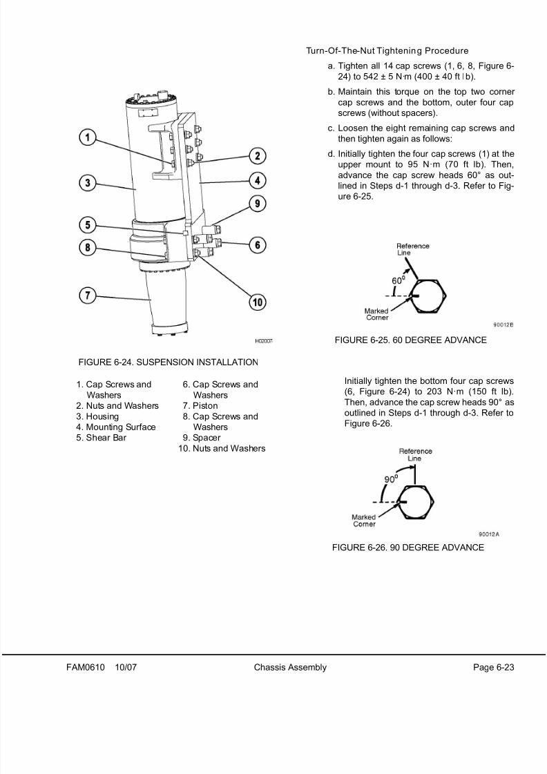
Turn-Of-The-Nut Tightening Procedure
a. Tighten all 14 cap screws (1, 6, 8, Figure 6
24) to 542 ± 5 N·m (400 ± 40 ft lb).
b. Maintain this torque on the top two corne
cap screws and the bottom, outer four cap
screws (without spacers).
c. Loosen the eight remaining cap screws and
then tighten again as follows:
d. Initially tighten the four cap screws (1) at the
upper mount to 95 N·m (70 ft lb). Then
advance the cap screw heads 60° as out
lined in Steps d-1 through d-3. Refer to Fig
ure 6-25.
Initially tighten the bottom four cap screws
(6, Figure 6-24) to 203 N·m (150 ft lb)
Then, advance the cap screw heads 90° asoutlined in Steps d-1 through d-3. Refer to
Figure 6-26.
FIGURE 6-24. SUSPENSION INSTALLATION
1. Cap Screws and
Washers
2. Nuts and Washers3. Housing
4. Mounting Surface
5. Shear Bar
6. Cap Screws and
Washers
7. Piston8. Cap Screws and
Washers
9. Spacer
10. Nuts and Washers
FIGURE 6-25. 60 DEGREE ADVANCE
FIGURE 6-26. 90 DEGREE ADVANCE

8/17/2019 Ce Aw 004101
http://slidepdf.com/reader/full/ce-aw-004101 58/265
Page 6-24 Chassis Assembly 10/07 FAM0610
1.) Mark a reference line on a corner of the
hexagonal cap screw head or nut and the
mounting surface opposite this corner, as
shown. Then mark the position located
60° or 90° clockwise relative to the first
reference line on the mounting surface.
Refer to Figures 6-28 and 6-29.
2.) Scribe a reference mark at the opposite
end of the turning member to ensure that
either the cap screw head or nut, remains
stationary.
3.) Each corner of a hexagon represents 60°.
The turning member, either the cap screw
head or nut, is turned until the marked
corner is adjacent with the marked refer-
ence line. Prevent the opposite end of the
turning member from turning during the
tightening procedure.
NOTE: Do not exceed 4 rpm tightening
speed. Do not hammer or jerk the wrenchduring the tightening procedure.
e. Loosen the top two corner cap screws (1,
Figure 6-24) and the bottom outer four cap
screws (8), (without spacers).
1.) Tighten the top two corner cap screws to
95 N·m (70 ft lb), then advance the cap
screw heads 60°.
2.) Tighten the bottom, outer four cap screws
to 203 N·m (150 ft lb), then advance the
cap screw heads 90°.
NOTE: If for any reason, these fasteners need to bechecked for tightness after completing this
procedure, loosen and inspect all 14 cap screws and
repeat the entire process. The hardware must be
cleaned and lubricated.
8/17/2019 Ce Aw 004101
http://slidepdf.com/reader/full/ce-aw-004101 59/265
FAM0610 10/07 Chassis Assembly Page 6-25
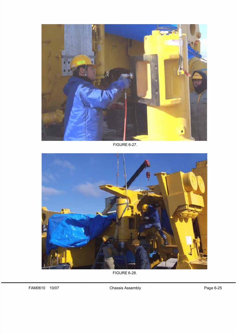
FIGURE 6-27.
FIGURE 6-28.

8/17/2019 Ce Aw 004101
http://slidepdf.com/reader/full/ce-aw-004101 60/265
Page 6-26 Chassis Assembly 10/07 FAM0610
19. Clean the tapered portion of the suspension rod and the bore of the spindle. Lubricate the two surfaces with
multi purpose grease number 2 (5% molybdenum disulphide).
20. Lift the spindle/brake assembly and retainer plate into position. The weight of each spindle/brake assembly is
approximately 3300 kg (7340 lb).
21. Lift the retainer plate into position under the spindle. The weight of the plate is approximately 30 kg (66 lb).
Install the twelve retainer plate cap screws. Alternately tighten the cap screws to 678 N·m (500 ft lb). Con-
tinue to tighten the cap screws in increments of 330 N·m (250 ft lb) until 2705 ± 270 N·m (1,995 ± 200 ft lb ) is
reached.
Repeat the previous steps for the remaining wheel.
8/17/2019 Ce Aw 004101
http://slidepdf.com/reader/full/ce-aw-004101 61/265
FAM0610 10/07 Chassis Assembly Page 6-27
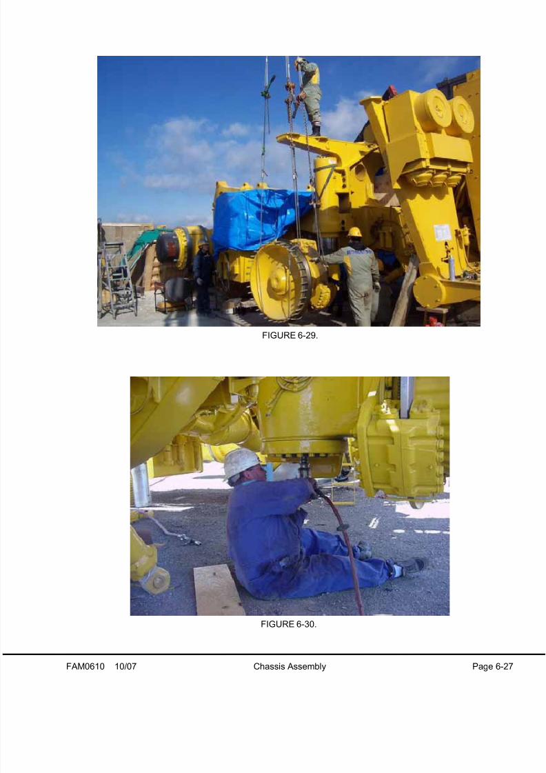
FIGURE 6-29.
FIGURE 6-30.

8/17/2019 Ce Aw 004101
http://slidepdf.com/reader/full/ce-aw-004101 62/265
Page 6-28 Chassis Assembly 10/07 FAM0610
22. Clean and prepare the steering cylinder and tie rod mounting surfaces.
23. Move the steering cylinders into position in the steering arms bores. Lubricate the pin and pin bore surfaces
with multi purpose grease number 2 (5% molybdenum disulphide). Install the pin, spacers, bearing seals and
hardware to each joint. Tighten the pin retainer cap screws to standard torque. Refer to Standard Tables in
Section 10, Appendix.
NOTE: Use alignment sleeve (TY4576) to aid in assembly of the steering cylinder joints.
24. Lift the tie rod into position. The weight of the tie rod is approximately 136 kg (300 lb). Lubricate the pin and
pin bore surfaces with multi purpose grease number 2 (5% molybdenum disulphide). Install the pin, spacers,
bearing seals and hardware to each joint. Tighten the pin retainer cap screws to standard torque.
The tie rod toe-in must be adjusted once the tires and the body are installed. The toe-in adjustment procedure
is located in Section 10, Appendix.
NOTE: Use alignment sleeve (TY4576) to aid in assembly of the tie rod joints.
FIGURE 6-31.
1. Steering Cylinder
2. Tie Rod Assembly
3. Retainer
4. Locknut
5. Spacer
6. Bearing Seal
7. Spherical Bearing
8. Steering Arm
9. Cap Screw
10. Bearing Retainer
11. Cap Screw
12. Lockwasher
13. Washer
14. Cap Screw
15. Pin
16. Cap Screw
17. Retainer Plate
18. Flat Washer
Refer to the illustration on the following page.

8/17/2019 Ce Aw 004101
http://slidepdf.com/reader/full/ce-aw-004101 63/265
FAM0610 10/07 Chassis Assembly Page 6-29
FIGURE 6-32.

8/17/2019 Ce Aw 004101
http://slidepdf.com/reader/full/ce-aw-004101 64/265
Page 6-30 Chassis Assembly 10/07 FAM0610
19. Lift the contactor box into position on the retarding grid. Install the mounting hardware and tighten to standard
torque. Refer to Standard Tables in Section 10, Appendix.
20. Lift the RH deck into position on the truck. The weight of the assembly is approximately 4600 kg (10,141 lb).
Loosely install the deck mounting hardware.
NOTE: Do not torque the hardware until after all decks are in place.

8/17/2019 Ce Aw 004101
http://slidepdf.com/reader/full/ce-aw-004101 65/265
FAM0610 10/07 Chassis Assembly Page 6-31
FIGURE 6-33.
FIGURE 6-34.

8/17/2019 Ce Aw 004101
http://slidepdf.com/reader/full/ce-aw-004101 66/265
Page 6-32 Chassis Assembly 10/07 FAM0610
21. Install the handrails onto the LH deck and lift the deck into place. The weight of the LH deck with handrails is
approximately 635 kg (1400 lb). Loosely install the eight deck mounting cap screws.
NOTE: Do not torque the hardware until after all decks are in place.
8/17/2019 Ce Aw 004101
http://slidepdf.com/reader/full/ce-aw-004101 67/265
FAM0610 10/07 Chassis Assembly Page 6-33
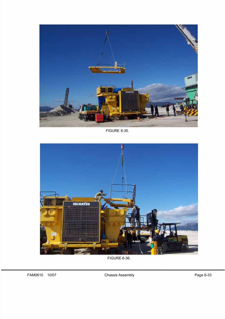
FIGURE 6-35.
FIGURE 6-36.

8/17/2019 Ce Aw 004101
http://slidepdf.com/reader/full/ce-aw-004101 68/265
Page 6-34 Chassis Assembly 10/07 FAM0610
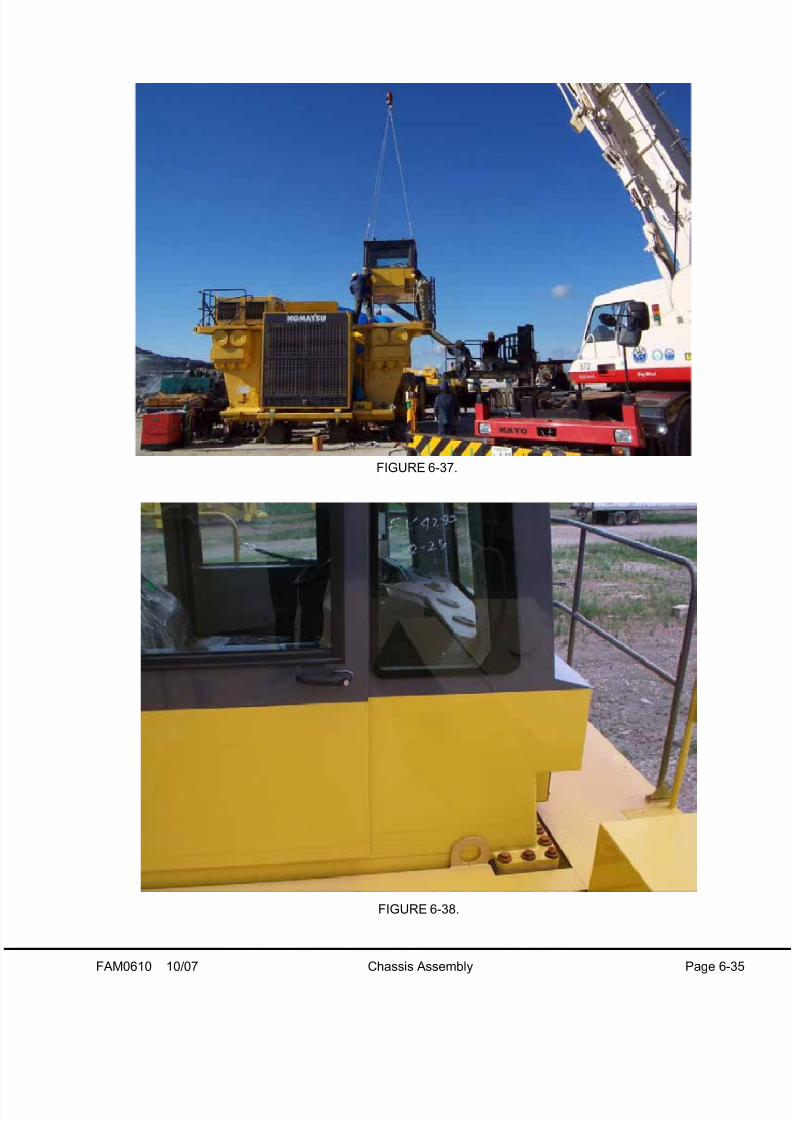
22. Tap the cab mounting holes to remove any paint before cab installation.
23. Lift the operator cab into position. The weight of the cab is approximately 2449 kg (5400 lb).
Install and tighten the forty cap screws to standard torque. Refer to Standard Tables in Section 10, Appendix.
8/17/2019 Ce Aw 004101
http://slidepdf.com/reader/full/ce-aw-004101 69/265

8/17/2019 Ce Aw 004101
http://slidepdf.com/reader/full/ce-aw-004101 70/265
Page 6-36 Chassis Assembly 10/07 FAM0610
24. Lift the air intake tubes into place. The weight of the LH tube is approximately 15 kg (33 lb). The weight of the
RH tube is approximately 28 kg (62 lb). Secure the tubes in place with the hump hoses and clamps.

8/17/2019 Ce Aw 004101
http://slidepdf.com/reader/full/ce-aw-004101 71/265
FAM0610 10/07 Chassis Assembly Page 6-37
FIGURE 6-39.
FIGURE 6-40.

8/17/2019 Ce Aw 004101
http://slidepdf.com/reader/full/ce-aw-004101 72/265
Page 6-38 Chassis Assembly 10/07 FAM0610
25. Lift the center deck into position on the truck. The weight of the deck is approximately 233 kg (514 lb). Install
the deck mounting cap screws and tighten to standard torque. Refer to Standard Tables in Section 10, Appen-
dix.
26. Lift the diagonal ladder into position on the truck. The weight of the ladder is approximately 130 kg (287 lb).
Install the ladder mounting hardware and tighten to standard torque.

8/17/2019 Ce Aw 004101
http://slidepdf.com/reader/full/ce-aw-004101 73/265
FAM0610 10/07 Chassis Assembly Page 6-39
FIGURE 6-41.
FIGURE 6-42.

8/17/2019 Ce Aw 004101
http://slidepdf.com/reader/full/ce-aw-004101 74/265
Page 6-40 Chassis Assembly 10/07 FAM0610
27. Tighten the cap screws that secure the diagonal ROPS beam and the decks. Tighten the cap screws to stan-
dard torque.Refer to Standard Tables in Section 10, Appendix.
28. Weld the uprights in place. Refer to Figure 6-45 for welding specifications.
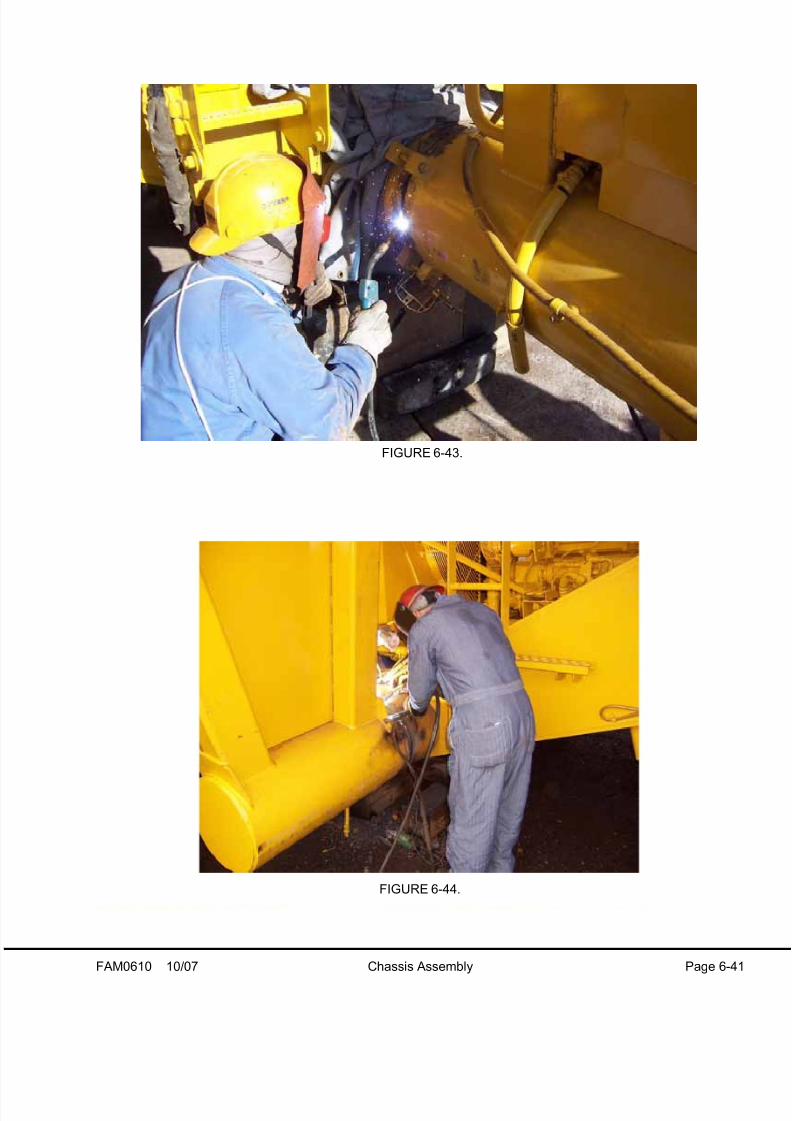
8/17/2019 Ce Aw 004101
http://slidepdf.com/reader/full/ce-aw-004101 75/265
FAM0610 10/07 Chassis Assembly Page 6-41
FIGURE 6-43.
FIGURE 6-44.

8/17/2019 Ce Aw 004101
http://slidepdf.com/reader/full/ce-aw-004101 76/265
Page 6-42 Chassis Assembly 10/07 FAM0610
FIGURE 6-45.

8/17/2019 Ce Aw 004101
http://slidepdf.com/reader/full/ce-aw-004101 77/265
FAM0610 10/07 Chassis Assembly Page 6-43
NOTES

8/17/2019 Ce Aw 004101
http://slidepdf.com/reader/full/ce-aw-004101 78/265
Page 6-44 Chassis Assembly 10/07 FAM0610
29. Raise the front of the truck for front wheel instal-
lation.
NOTE: Clean the mating surfaces before installing
the wheels.
30. Using a tire handler, lift the front wheel into posi-
tion on the wheel hub. Install the wheel retainer
lugs and lubricated nuts. Evenly tighten each
nut using the sequence shown in Figure 6-46 to407 N·m (300 ft lbs).
31. Spin the wheel and check the rim run-out. Maxi-
mum run-out is 5 mm (0.20 in.). If run-out
exceeds specifications, loosen all nuts and re-
tighten them in the proper sequence.
32. If run-out is within specifications, then tighten
each nut in the proper sequence to 746 N·m.
(550 ft lbs).
33. Connect the valve stem to the wheel hub.
34. After truck assembly operate the truck for one
load and retighten the wheel nuts, as specified.Recheck the nut torque daily (each 24 hours of
operation) to ensure proper torque is main-
tained on each nut. Once torque is maintained,
daily checking is no longer required. Check
intermittently to ensure torque is maintained.
FIGURE 6-46. FRONT WHEEL TIGHTENING
SEQUENCE
FIGURE 6-47.

8/17/2019 Ce Aw 004101
http://slidepdf.com/reader/full/ce-aw-004101 79/265
FAM0610 10/07 Chassis Assembly Page 6-45
35. Attach the tire handler (or lifting device) to the
inner dual and install the inner dual onto the
wheel motor hub. Do not damage the tire infla-
tion extension line.
NOTE: During inner wheel installation, ensure the air
inflation line lays in the channel on the wheel hub
assembly.
36. Using a lifting device, install the rear wheel
spacer onto the wheel motor hub. Tap the
spacer up against the inner dual.
37. Attach the tire handler to the outer dual and
position onto the wheel motor hub.
NOTE: Position the outer dual wheel so that the tire
valve bracket aligns with the inner wheel inflation
line.
38. Install the wedges onto the studs and secure inplace with the lubricated wheel nuts. Evenly
tighten each nut in an alternating pattern, as
shown in Figure 6-48, to 407 N·m (300 ft lbs).
39. Spin the wheel and check the rim run-out. Maxi-
mum run-out is 5 mm (0.20 in.). If the run-out
exceeds specifications, then loosen all the nuts
and re-tighten them evenly in the proper
sequence.
40. If run-out is within specifications, tighten each
nut in the proper sequence to 746 N·m (550 ft
lbs).
41. Secure the inner and outer dual tire inflationlines to the bracket on the outer rim. Tighten the
cap screws to standard torque.
42. Install the wheel cover. Remove the blocks from
under the truck and lower the truck to the
ground.
43. After truck assembly is complete, operate the
truck for one load and retighten the wheel nuts
in the proper sequence. Recheck the nut torque
daily (each 24 hours of operation) to ensure
proper torque is maintained on each nut. Once
the torque is maintained, daily checking is no
longer required. Check intermittently to ensuretorque is maintained.
FIGURE 6-48. REAR WHEEL TIGHTENING
SEQUENCE

8/17/2019 Ce Aw 004101
http://slidepdf.com/reader/full/ce-aw-004101 80/265
Page 6-46 Chassis Assembly 10/07 FAM0610
FIGURE 6-49.
FIGURE 6-50.

8/17/2019 Ce Aw 004101
http://slidepdf.com/reader/full/ce-aw-004101 81/265
FAM0610 10/07 Chassis Assembly Page 6-47
FIGURE 6-51.
FIGURE 6-52.
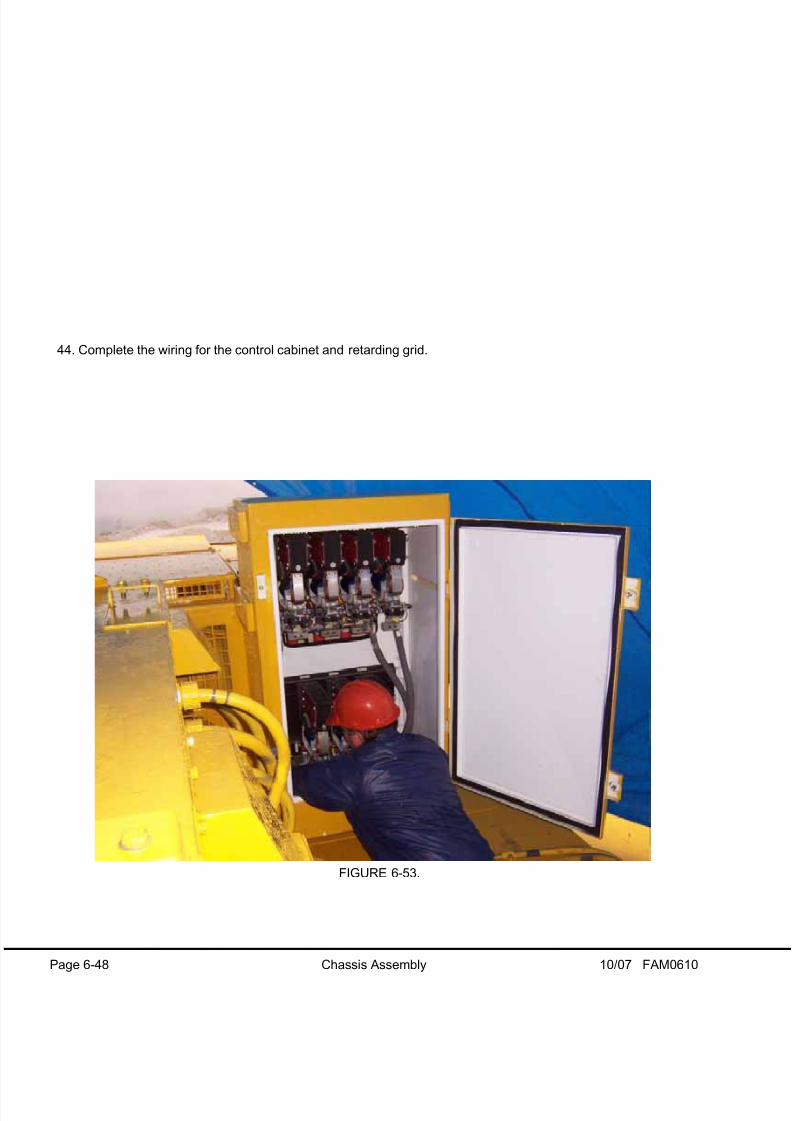
8/17/2019 Ce Aw 004101
http://slidepdf.com/reader/full/ce-aw-004101 82/265
Page 6-48 Chassis Assembly 10/07 FAM0610
44. Complete the wiring for the control cabinet and retarding grid.
FIGURE 6-53.

8/17/2019 Ce Aw 004101
http://slidepdf.com/reader/full/ce-aw-004101 83/265
FAM0610 10/07 Chassis Assembly Page 6-49
FIGURE 6-54.
FIGURE 6-55.
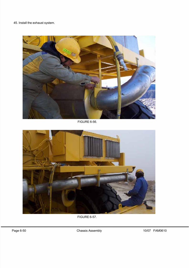
8/17/2019 Ce Aw 004101
http://slidepdf.com/reader/full/ce-aw-004101 84/265
Page 6-50 Chassis Assembly 10/07 FAM0610
45. Install the exhaust system.
FIGURE 6-56.
FIGURE 6-57.
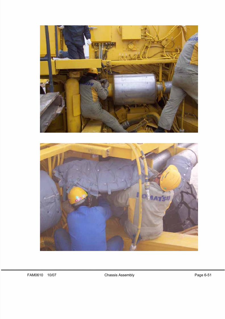
8/17/2019 Ce Aw 004101
http://slidepdf.com/reader/full/ce-aw-004101 85/265
FAM0610 10/07 Chassis Assembly Page 6-51

8/17/2019 Ce Aw 004101
http://slidepdf.com/reader/full/ce-aw-004101 86/265

8/17/2019 Ce Aw 004101
http://slidepdf.com/reader/full/ce-aw-004101 87/265
FAM0610 10/07 Chassis Assembly Page 6-53
FIGURE 6-59.
FIGURE 6-60.

8/17/2019 Ce Aw 004101
http://slidepdf.com/reader/full/ce-aw-004101 88/265
Page 6-54 Chassis Assembly 10/07 FAM0610
FIGURE 6-61.
FIGURE 6-62.

8/17/2019 Ce Aw 004101
http://slidepdf.com/reader/full/ce-aw-004101 89/265
FAM0610 10/07 Chassis Assembly Page 6-55
NOTES

8/17/2019 Ce Aw 004101
http://slidepdf.com/reader/full/ce-aw-004101 90/265
Page 6-56 Chassis Assembly 10/07 FAM0610
48. Install the hangers to the intake and exhaust tubes.

8/17/2019 Ce Aw 004101
http://slidepdf.com/reader/full/ce-aw-004101 91/265
FAM0610 10/07 Chassis Assembly Page 6-57
FIGURE 6-63.
FIGURE 6-64.

8/17/2019 Ce Aw 004101
http://slidepdf.com/reader/full/ce-aw-004101 92/265
Page 6-58 Chassis Assembly 10/07 FAM0610
49. Install and wire the battery boxes. Refer to the electrical schematic for reference.

8/17/2019 Ce Aw 004101
http://slidepdf.com/reader/full/ce-aw-004101 93/265
FAM0610 10/07 Chassis Assembly Page 6-59
FIGURE 6-65.
FIGURE 6-66.

8/17/2019 Ce Aw 004101
http://slidepdf.com/reader/full/ce-aw-004101 94/265
Page 6-60 Chassis Assembly 10/07 FAM0610
50. Finish routing and connecting remaining hydraulic, electric, and lubrication connections. Install the clamping
for each component.
51. After the chassis assembly is complete, the body can be installed. Refer to Section 8 for more information.
FIGURE 6-67.

8/17/2019 Ce Aw 004101
http://slidepdf.com/reader/full/ce-aw-004101 95/265
FAM0610 10/07 Chassis Assembly Page 6-61
FIGURE 6-68.
FIGURE 6-69.

8/17/2019 Ce Aw 004101
http://slidepdf.com/reader/full/ce-aw-004101 96/265

8/17/2019 Ce Aw 004101
http://slidepdf.com/reader/full/ce-aw-004101 97/265
FAM0710 Dump Body Assembly 7-1
DUMP BODY ASSEMBLY
GENERAL INFORMATION
The total weight of the body is approximately
26,853 kg (59,201 lb). Use two cranes for assem-
bling the body. A 45 metric ton (50 ton) crane and
a 109-136 metric tons (120-150 ton) crane are
required. The larger crane is needed to help turn
the body over after completion of the underside
welding.
Assembly of the body must be performed on flat ter-
rain with an adequate area for welding machines and
for maneuvering lifting equipment.
Body sections must be assembled as originally
manufactured. Match the shipping numbers sten-
ciled on the body sections to mate the correct
parts. DO NOT mix components.
If the body is being welded in a cold climate, it is
advisable to move the parts to be welded into an
enclosed shop area. Surfaces to be welded must be
dry and the temperature must be above 10°C (50°F)
If shop space is not available, it may be necessary to
provide a portable enclosure and pre-heat the parts
prior to welding.
In most instances, it is easier to assemble and weld
the body while the sections are upside down. Afte
the pivot, guide pin, and body pads are welded in
place, the body can be turned over and the remain-
der of the assembly can be completed.
All paint must be removed from surfaces to be
welded. Use a wire brush or paint removal equip-
ment.
Refer to the assembly blueprints shipped with the
truck for specific welding details and the parts
required for assembly.
1. Canopy
2. Front Sheet
3. RH Side Sheet
4. Lift Hole
5. Floor
6. Pivot
7. LH Side Sheet
FIGURE 7-1. BODY PARTS NOMENCLATURE

8/17/2019 Ce Aw 004101
http://slidepdf.com/reader/full/ce-aw-004101 98/265
7-2 Dump Body Assembly FAM0710
BODY ASSEMBLY
NOTE: References to LH and RH in the following
procedures assume the body is in its' normal, upright
position, as shown in Figure 7-1.
1. Organize the body sections in a large, flat,
open space. Position the sections side by side
and upside down. Arrange the sections so theyare properly oriented for assembly. Refer to
Figure 7-2 for domestic configuration, and 7-3
for international configuration.
2. Remove the paint from the weld areas.
3. Lift the RH body half and support the front
sheet, side sheets, and rear edge of the floor
with blocks. Refer to Figure 7-4.
4. Lift the LH body and support with blocks under
the front sheet and side sheet. Position a
hydraulic jack on blocks at the tail end to sup-
port the floor at the rear. Refer to Figure 7-5.
5. Use the hydraulic jack to align the body halves
at the rear. Install cap screw (1, Figure 7-5) and
the sleeve.
NOTE: Figure 7-5 shows the hardware numbered in
installation sequence. Cap screws (1, 2 & 7) aremarked with an asterisk (*). These cap screws are
installed with sleeves. The remainder of the cap
screws do not have sleeves.
6. Install cap screw (2) and the sleeve at the front
of the floor.
7. Install cap screw (3) in the front sheet near the
floor. Attach a wedge or a clamp inside the
body as necessary to align the front sheet.
8. Use a wedge to align the front sheet and can-
opy. Install cap screws (4, 5 & 6).
9. Install cap screw (7) and the sleeve in the frontof the canopy.
10. Install cap screws (8 & 9).
11. Install the backer strips on the front sheet center
joint as shown on the assembly blueprint.
NOTE: The backer strips must be tack welded in a
location where the tack will be burned away on the
first pass.
12. Loosely install cap screws (10 & 11) in the floor.
13. Loosen cap screws (1 & 2).
14. Attach appropriate lifting apparatus to the bodypivot. Insert the lifting apparatus through the
body pin bores. The weight of the pivot is
approximately 1492 kg (3289 lb). DO NOT dam-
age the bores.
15. Lift the pivot over the body. Lower the pivot into
position against the rear of the body, as shown
in Figure 7-6. Align the pivot with the body sills.
FIGURE 7-2. DOMESTIC LAYOUT
FIGURE 7-3. INTERNATIONAL LAYOUT
FIGURE 7-4.

8/17/2019 Ce Aw 004101
http://slidepdf.com/reader/full/ce-aw-004101 99/265

8/17/2019 Ce Aw 004101
http://slidepdf.com/reader/full/ce-aw-004101 100/265
7-4 Dump Body Assembly FAM0710
16. If necessary, use a hydraulic jack or crane to
raise the center of the body to allow the pivot to
fit inside the bolsters. Loosely install the cap
screws in the pivot.
17. If assembling an international body (three-
piece), lift the canopy into position at this time.
Install the canopy cap screws and tighten.
18. Tighten all floor, front sheet, and canopy capscrews. Use a chalk line to align the front of the
canopy.
19. Tighten the pivot cap screws.
20. Install the filler plates and backer strips for the
pivot to body sill weld joints.
21. Check the alignment and fit of all components
22. Tack weld the joints.
BODY WELDING
Follow the guidelines listed below when welding the
body:
• Use dry weld rod or weld wire.
• Weld surfaces must be dry and above 10°C(50°F).
• If stick electrode is used, use as large a diameter rod as practical to weld the floor and front sheet
joints.
• The following sequence must be followed for thefront sheet:
First Pass: Back step and skip weld in 10increments along the entire length of the joint.Refer to Figure 7-7.
Repeat the same procedure until the entire jointis filled. DO NOT stop welding until entire joint iscomplete.
• The body floor “V” groove must also be weldedusing the same procedure as the front sheet.Weld from the front to the rear. Refer to Figure 7-7.
1. Complete the welds at the center seam, the
front sheet and the canopy. Refer to the assem-
bly blueprints for welding requirements.
2. Remove the canopy alignment blocks.
FIGURE 7-7. FRONT SHEET & FLOOR JOINT
WELDING SEQUENCE

8/17/2019 Ce Aw 004101
http://slidepdf.com/reader/full/ce-aw-004101 101/265
FAM0710 Dump Body Assembly 7-5
3. Install the remaining gussets, the body guide
and the body pad mounts. Refer to Figures 7-8
through 7-11.
DO NOT install the heated body exhaust boxes
onto the body at this time. The exhaust boxes
must be installed after the body is installed onto
the truck.
4. Once the body underside is completed, the
body can be turned over. Use two cranes to
invert the body, a 45 metric ton (50 ton) crane
and a 109-136 metric ton (120-150 ton) crane
The following photographs show a typicaexample of a body being inverted with two
cranes.
Position the body onto support blocks as shown
in Figure 7-18.
FIGURE 7-8.
FIGURE 7-9.
FIGURE 7-10.
FIGURE 7-11.

8/17/2019 Ce Aw 004101
http://slidepdf.com/reader/full/ce-aw-004101 102/265
7-6 Dump Body Assembly FAM0710
FIGURE 7-12.
FIGURE 7-13.
FIGURE 7-14.
FIGURE 7-15.
FIGURE 7-16.
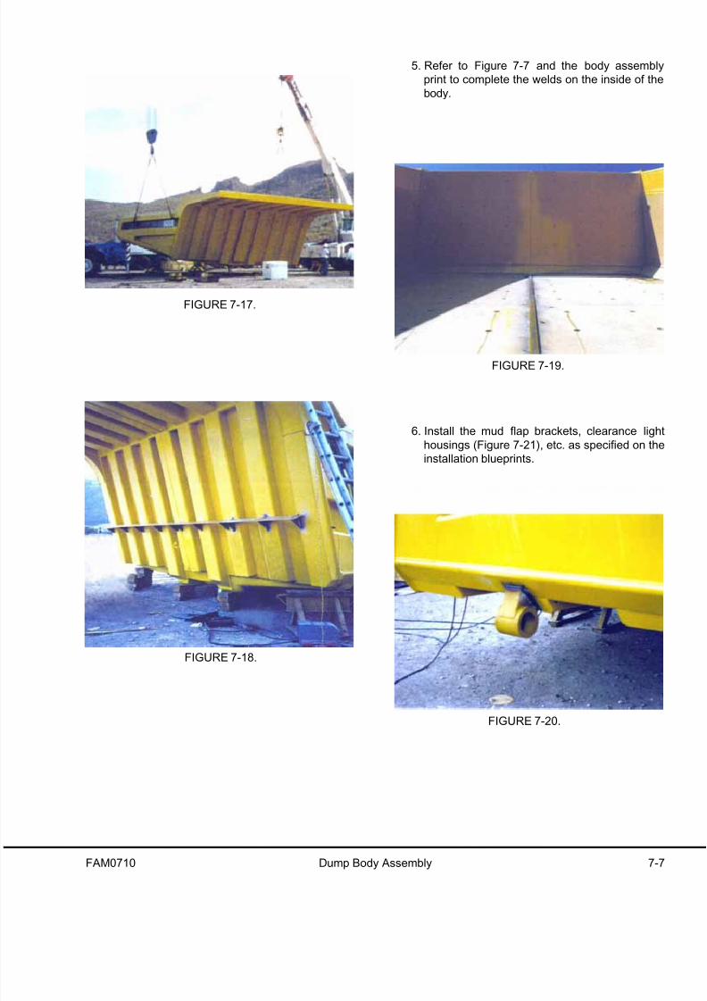
8/17/2019 Ce Aw 004101
http://slidepdf.com/reader/full/ce-aw-004101 103/265

8/17/2019 Ce Aw 004101
http://slidepdf.com/reader/full/ce-aw-004101 104/265
7-8 Dump Body Assembly FAM0710
7. Install any optional equipment such as body lin-
ers and side boards.
8. Clean the weld joints and paint.

8/17/2019 Ce Aw 004101
http://slidepdf.com/reader/full/ce-aw-004101 105/265
FAM0809 Dump Body Installation Page 8-1
DUMP BODY INSTALLATION
Installation
Before raising or lifting the body, ensure there is adequate clearance between the body and overhead
structures or electric power l ines.
Body weight can vary substantially, depending on liner plate installation, etc. Ensure the lifting device is
rated for at l east a 45 ton capacity.
1. Attach the lifting device to the dump body and lower over the truck frame. Align the body pivot and frame pivo
holes.
2. Install shims (3, Figure 8-3), as required, to center the body on the frame pivot.
NOTE: A minimum of one shim is required at the outside end of the frame pivot. DO NOT install shims at the
inside.
FIGURE 8-1.
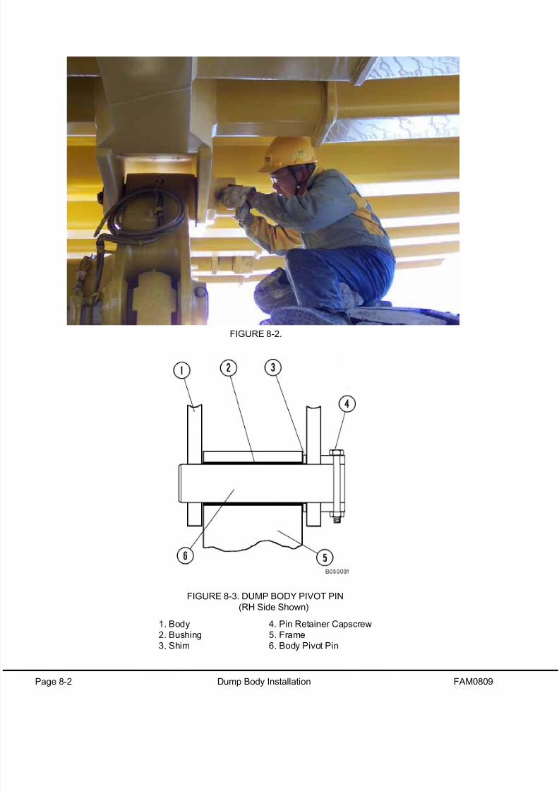
8/17/2019 Ce Aw 004101
http://slidepdf.com/reader/full/ce-aw-004101 106/265
Page 8-2 Dump Body Installation FAM0809
FIGURE 8-2.
FIGURE 8-3. DUMP BODY PIVOT PIN
(RH Side Shown)
1. Body
2. Bushing
3. Shim
4. Pin Retainer Capscrew
5. Frame
6. Body Pivot Pin

8/17/2019 Ce Aw 004101
http://slidepdf.com/reader/full/ce-aw-004101 107/265
FAM0809 Dump Body Installation Page 8-3
3. Align the pin retainer cap screw hole and push the pivot pin through the spacers and into the pivot bushings in
each side of the frame.
4. Install the cap screw through each pin and tighten the nuts to standard torque.
5. Align the hoist cylinder upper mounting eye with the body. Align the retaining cap screw hole and install the
pin.
6. Install the pin retaining cap screws and nuts and tighten to standard torque.
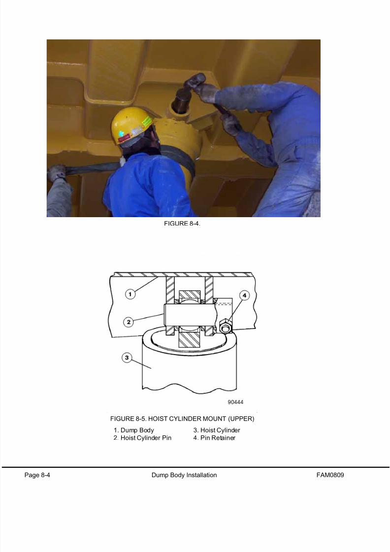
8/17/2019 Ce Aw 004101
http://slidepdf.com/reader/full/ce-aw-004101 108/265
Page 8-4 Dump Body Installation FAM0809
FIGURE 8-4.
FIGURE 8-5. HOIST CYLINDER MOUNT (UPPER)
1. Dump Body
2. Hoist Cylinder Pin
3. Hoist Cylinder
4. Pin Retainer

8/17/2019 Ce Aw 004101
http://slidepdf.com/reader/full/ce-aw-004101 109/265
FAM0809 Dump Body Installation Page 8-5
BODY SLING
Any t ime personnel are required to per form main-
tenance on the vehicle with the dump body in the
raised position, the body must be supported in
the raised position with t he body sling cable.
Inspect the cable and mounting brackets for
signs o f fatigue or wear before use.
1. To lock the dump body in the UP position, raise
the body to its maximum height.
2. Remove the pins storing the sling in the storage
position and place the cable clevis over the eye
below the rear suspension mount and eye on
the body. Reinsert the pins and retainers.
3. Slowly lower the body until the cable is tight.4. After the work has been completed, raise the
body, unhook the cable, and reattach to its stor-
age position.
BODY PADS
NOTE: It is not necessary to remove the dump body
to replace the body pads. The pads must be
inspected during scheduled maintenance inspections
and replaced if worn excessively.
1. Raise the body to a height sufficient to allow
access to all pads.
Place the blocks between the body and frame
Secure the blocks in place.
2. Place the pad and shims into position. Instal
the mounting hardware and tighten to 34 N·m
(25 ft lbs). Repeat at each pad location.
3. Raise the body, remove the blocks supportingthe body, and lower the body onto the frame.
FIGURE 8-6. BODY PAD
1. Dump Body
2. Shim
3. Pad Mounting Hardware
4. Body Pad
5. Frame

8/17/2019 Ce Aw 004101
http://slidepdf.com/reader/full/ce-aw-004101 110/265
Page 8-6 Dump Body Installation FAM0809
Ad justment
1. All pads, except the rear pad on each side, must contact the frame with approximately equal compression of
the rubber. A gap of approximately 1.5 mm (0.06 in.) is required at each rear pad. This can be accomplished
by using one less shim at each rear pad. If the pad contact appears to be unequal, repeat the above proce-
dure. The vehicle must be parked on a flat, level surface for inspection.
Proper body pad to frame contact is required to ensure maximum pad life.
FIGURE 8-7.
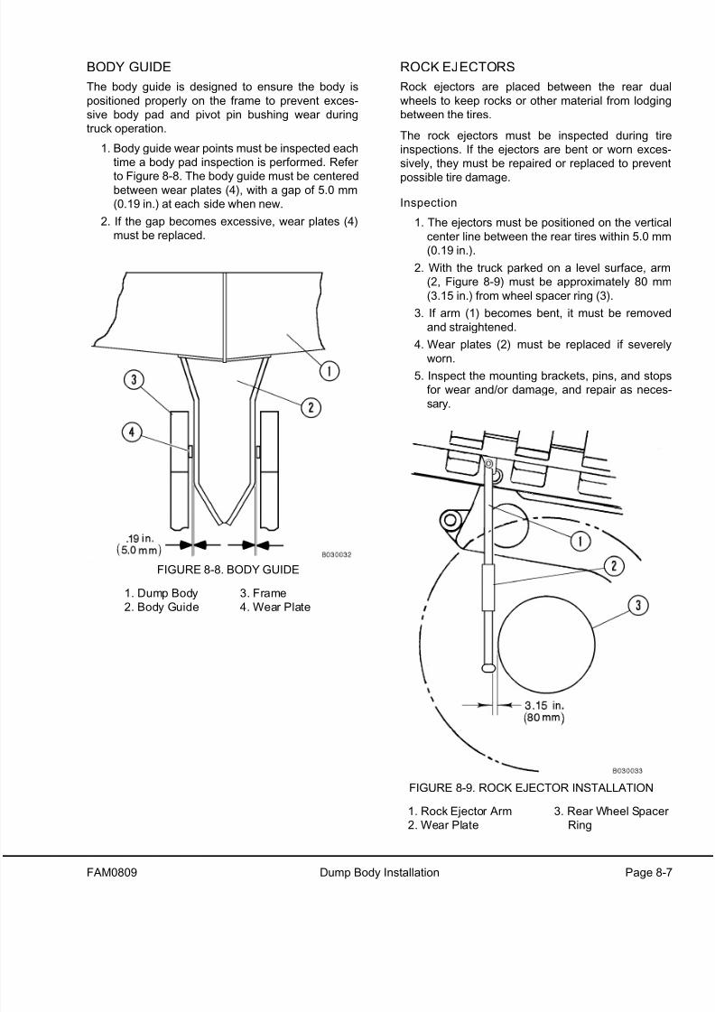
8/17/2019 Ce Aw 004101
http://slidepdf.com/reader/full/ce-aw-004101 111/265

8/17/2019 Ce Aw 004101
http://slidepdf.com/reader/full/ce-aw-004101 112/265
Page 8-8 Dump Body Installation FAM0809
BODY SWITCHES
Refer to Figure 8-10 to properly position the body
switches.
FINAL ASSEMBLY
Install the remaining items to the body and associ-ated components including: lubrication lines, mud
flaps, decals, body position indicator, etc.

8/17/2019 Ce Aw 004101
http://slidepdf.com/reader/full/ce-aw-004101 113/265
FAM0809 Dump Body Installation Page 8-9
F I G U R E
8 - 1 0 .

8/17/2019 Ce Aw 004101
http://slidepdf.com/reader/full/ce-aw-004101 114/265
Page 8-10 Dump Body Installation FAM0809
NOTES
8/17/2019 Ce Aw 004101
http://slidepdf.com/reader/full/ce-aw-004101 115/265
FAM0903 Final Checkout Page 9-1
FINAL CHECKOUT
Final checkout requires truck operation.
Place the operation and maintenance manual and
safety manuals in the operator cab, if not already there.
Any personnel involved in the final check-out of the
truck must read and understand all safety and operat-
ing instructions in the operation and maintenance man-ual.
1. Complete delivery and warranty forms.
2. Check all coolant and lubricants for proper levels
and specifications. The lubrication chart is shown
in Section 10, Appendix.
3. Verify the shut-off valves in the hydraulic cabinet
are open.
4. Purge any air from the pumps. Pressure will no
build if air is present. Operating the pumps with ai
in the system will result in damage.
5. Perform a final check of all systems and prepare
for operation. Several checks and tasks are out-
lined in Section 10, Appendix.
6. Complete the checks listed in the Field Assembly
Inspection Report Form. A copy of the form is pro
vided with the truck and is also available in Sec-
tion 10, Appendix.
7. Operate the truck in a traffic-free area until safe
operation has been validated.
8. Release the truck for use after all checks have
been completed and all deficiencies corrected.

8/17/2019 Ce Aw 004101
http://slidepdf.com/reader/full/ce-aw-004101 116/265
Page 9-2 Final Checkout FAM0903
NOTES

8/17/2019 Ce Aw 004101
http://slidepdf.com/reader/full/ce-aw-004101 117/265
FAM1005 Appendix Page 10-1
APPENDIX
This chapter contains additional information and procedures for aiding in field assembly of the truck. Refer to the
list below for contents of this chapter. Refer to the latest service manual for additional information on servicing the
truck.
1. Lubrication Chart - WB2790
2. Suspension Oiling And Charging
3. Toe In Adjustment
4. Automatic Lubrication System Checkout
5. Air Conditioning Checkout Procedure - EL4302
6. Air Conditioning Drive Belt Adjustment Procedure - EL9330
7. Hydraulic Checkout Procedure - EL2601
8. Brake Checkout Procedure - EF5761
9. VHMS Checkout Procedure - EK8480
10. Payload Meter III Checkout Procedure - EJ3061
11. Electrical Checkout Procedure - EK8477
12. Standard Torque Charts and Conversion Tables
13. Field Assembly Inspection Report
14. 50 Hour Post Commissioning Checksheet

8/17/2019 Ce Aw 004101
http://slidepdf.com/reader/full/ce-aw-004101 118/265
Page 10-2 Appendix FAM1005
NOTES

8/17/2019 Ce Aw 004101
http://slidepdf.com/reader/full/ce-aw-004101 119/265
L U B R I C A T I O N
C H A R T

8/17/2019 Ce Aw 004101
http://slidepdf.com/reader/full/ce-aw-004101 120/265
NOTES

8/17/2019 Ce Aw 004101
http://slidepdf.com/reader/full/ce-aw-004101 121/265
Suspension Oiling and Charging
SUSPENSION OILING AND CHARGING
GENERAL
These procedures cover the oiling and charging of
Hydrair ®II suspensions on Komatsu 730E dump
trucks.
Suspensions, which have been properly charged, willprovide improved handling and ride characteristics
while also extending the fatigue life of the truck frame
and improving tire wear.
NOTE: Inflation pressures and exposed piston
lengths are calculated for a normal truck gross
vehicle weight (GVW). Additions to truck weight by
adding body liners, tailgates, water tanks, etc. will be
considered part of the payload. Keeping the truck
GVW within the specification, shown on the Grade/
Speed Retard chart in the operator cab, will extend
the service life of the truck main frame and allow the
Hydrair ®II suspensions to produce a comfortable ride.
Al l Hydrai r ®II suspensions are charged with com-
pressed nitrogen gas with sufficient pressure to
cause injury and/or damage if improperly han-
dled. Follow all safety instructions, cautions, and
warnings provided in the following procedures to
prevent any accidents during oi ling and charging.
Proper charging of Hydrair ®II suspensions requires
that three basic conditions be established in the fol-
lowing order:
1. The oil level must be correct.
2. The suspension piston rod extension for nitro-
gen charging must be correct.
3. The nitrogen charge pressure must be correct.
For best results, charge Hydrair ® II suspensions in pairs
(fronts together and rears together). If rears are to be
charged, the fronts must be charged first.
NOTE: For longer life of the suspension components
a friction modifier must be added to the suspension
oil. See Specifications chart, Figure 4-6, at the end othis chapter.
NOTE: Set up dimensions specified in the charts
must be maintained during oiling and charging
procedures. However, after the truck has been
operated, these dimensions may vary.
EQUIPMENT LIST
• Hydrair ® Charging Kit
• Jacks and/or Overhead Crane
• Support Blocks for:
Oiling Height Dimensions (Front and Rear)
Charging Height Dimensions (Front Only)
• Hydrair ® Oil (See Specifications Chart)
• Friction Modifier (See Specifications Chart)
• Dry Nitrogen (See Specifications Chart)
•
Hydrair ® Charging K it
Assemble service kit, as shown in Figure 4-1, and
attach to container of pure dry nitrogen gas (8).
Installation of Charging Kit
1. Remove protective covers and charging valve
caps from suspensions to be charged.
2. Turn T handle valve (1, Figure 4-1) of chargingvalve adapters (2) completely counterclockwise
3. Ensure manifold outlet valves (3) and inlet valve
(4) are closed (turned completely clockwise).

8/17/2019 Ce Aw 004101
http://slidepdf.com/reader/full/ce-aw-004101 122/265
Suspension Oiling and Charging
4. Turn swivel nut (small hex) on charging valve
three full turns counterclockwise to unseat the
valve.
5. Attach charging valve adapters (2) to each sus-
pension charging valve stem.
6. Turn T handle valve (1) clockwise. This will
depress the core of the charging valve and
open the gas chamber of the suspension.
7. Open both manifold outlet valves (3).
NOTE: By selective opening and closing of manifold
outlet valves (3) and inlet valve (4), suspensions may
be charged separately or together.
Removal of Charging Ki t
1. Close both manifold outlet valves (3).
2. Turn T handle valve (1) counterclockwise to
release charging valve cores.
3. Remove charging valve adapters (2) from the
charging valves.
4. If the charging valve is being reused, tighten
swivel nut (4, Figure 4-3) to 5.4 N·m (4 ft lbs).
5. If a new charging valve is being used, tighten
the swivel nut to 14.2 N·m (10.5 ft lbs). Loosen
and retighten swivel nut to 14.2 N·m (10.5 ft
lbs). Again loosen the swivel nut and retighten
to 5.4 N·m (4 ft lbs). Install valve cap (1) and
tighten to 3.3 N·m (2.5 ft lbs).
6. Install charging valve caps and protective cov-
ers on both suspensions.
Support Blocks For Oiling and Charging
Dimensions
Prior to starting the oiling and charging procedures,
supports must be fabricated which will maintain the
correct exposed piston rod extensions.
Nitrogen charging support blocks for the rear
suspension are not longer necessary. However,oiling blocks are necessary to properly set the
oiling height.
Exposed piston rod extensions are specified for both
oil level and nitrogen charging for Hydrair ®II suspen-
sions. These dimensions are listed in the tables
below Figures 4-2 and 4-5. Measure the dimensions
from the face of the cylinder gland to the machined
surface on the spindle at the front suspension. At the
rear suspension, measure from the face of the cylin-
der gland to the piston flange.
FIGURE 4-1. HYDRAIR® CHARGING KIT
NOTE: The arrangement of parts may vary from
the illustration above, depending on the kit p/n.
1. T Handle Valve
2. Charging Valve Adapter
3. Manifold Outlet Valves (from gauge)
4. Inlet Valve (from regulator)
5. Regulator Valve (nitrogen pressure)
6. Manifold
7. Charging Pressure Gauge (suspensions)
8. Dry Nitrogen Gas (Specifications Figure 4-6)

8/17/2019 Ce Aw 004101
http://slidepdf.com/reader/full/ce-aw-004101 123/265
Suspension Oiling and Charging
Support blocks may be made in various forms. Mild
steel materials are recommended. Square stock or
pipe segments [25 mm (1 in.) minimum] may be
used. Blocks must be capable of supporting the
weight of the truck during oiling and charging proce-
dures while avoiding contact with plated surfaces
and seals on the suspension. Refer to Figure 4-2 for
front suspension support block placement and Figure
4-4 for rear support block placement.
FRONT SUSPENSION
Al l Hydrair ®II suspensions are charged with com-
pressed nit rogen gas with sufficient pressure to
cause injury and/or damage if improperly han-dled. Follow all the safety notes, cautions, and
warnings in these procedures to prevent acci-
dents during servicing and charging.
1. Park the unloaded truck on a hard, level sur-
face. Apply the parking brake, and chock the
wheels.
2. Thoroughly clean the area around the charging
valve on the suspensions. Remove the protec-
tive covers from the charging valves.
Front Suspension Oiling
When the blocks are in place on a suspension,
they must be secured with a strap or other means
to avoid accidental discharge. An unsecured
block could fly loose as weight is applied, pre-
senting the possibility of serious injury to nearby
personnel and/or damage to the equipment.
Overhead clearance may be reduced rapid ly and
suddenly when nitrogen pressure is released!
NOTE: For longer life of suspension components, a
friction modifier must be added to the suspension oil
See the Oil and Nitrogen Specifications chart, Figure
4-6, at the end of this chapter.
1. Position and secure the oiling height dimension
blocks in place (Figure 4-2). When nitrogen
pressure is released, suspensions will lower torest on the blocks. Ensure the blocks do no
mar or scratch the plated surfaces of the pis-
tons or damage wiper seals in the lower bearing
retainer. Support blocks must seat on the spin
dle and the cylinder housing. The blocks must
be positioned 180° apart to provide stability.
Wear a face mask or goggles while relieving
nitrogen pressure.
2. Remove charging valve cap. Turn the charging
valve swivel nut (small hex) counterclockwise
three full turns to unseat the valve seal. DO
NOT turn the large hex. The charging valve
body has a bleeder groove in its mounting
threads, but for the safety of all personnel, the
valve body must not be loosened until all nitro
gen pressure has been vented from the suspen-
sion.
3. Depress the charging valve core to release the
nitrogen pressure from the suspension. Whenall nitrogen has been vented to the atmosphere
the suspension will have collapsed slowly and
be seated solidly on the support blocks
Remove the top fill plug next to the charging
valve (Figure 4-2).

8/17/2019 Ce Aw 004101
http://slidepdf.com/reader/full/ce-aw-004101 124/265
Suspension Oiling and Charging
4. Fill the suspension with clean Hydrair ® oil, with
6% friction modifier, until the cylinder is full to
the top of the fill plug bore. Drip pans must be
used and all spillage cleaned from outside of
the suspension. Allow the suspension to settle
for at least 15 minutes to clear any trapped
nitrogen and/or bubbles from the oil. Add moresuspension oil if necessary. Install a new fill
plug O-ring, and install the plug.
Front Suspension Nitrogen Charging
Lifti ng equipment (crane or hydraulic jacks) must
be of sufficient capacity to lift the weight of the
truck. Ensure that all personnel are clear of thelift area before the lift is started. Clearances
under the truck may be suddenly reduced.
1. If removed, install the charging valve with new
O-ring (9, Figure 4-3). Lubricate the O-ring with
clean Hydrair ®oil.
FRONT SUSPENSION DIMENSIONS (EMPTY)
TRUCK MODEL AND OPTIONS
OILINGHEIGHT
IN. (mm)
CHARGINGHEIGHT
IN. (mm)
CHARGINGPRESSUREpsi (kPa)
730E* 1.5 (38.1) 9.0 (229) 400 (2758)
* with standard rock body
Note: If truck starts to lift off blocks before charging pressure isattained, stop ch arging.
FIGURE 4-2. FRONT SUSPENSION
FIGURE 4-3. CHARGING VALVE
1. Valve Cap
2. Seal
3. Valve Core
4. Swivel Nut
5. Rubber Washer
6. Valve Body
7. O-Ring
8. Valve Stem
9. O-Ring

8/17/2019 Ce Aw 004101
http://slidepdf.com/reader/full/ce-aw-004101 125/265
Suspension Oiling and Charging
2. Tighten the valve body (large hex, 6) to 22.4
N·m (16.5 ft lbs). The valve swivel nut (small
hex, 4) must be unseated by turning counter-
clockwise three full turns.
Dry nitrogen is the only gas approved for use in
Hydrair ®II suspensions. Charging of these com-
ponents with oxygen or other gases may result in
an explosion which could cause fatalities, seri-
ous injuries, and/or major property damage. Use
only nitrogen gas meeting the specifications
shown in chart (Figure 4-6).
3. Install Hydrair ® charging kit and a bottle of pure
dry nitrogen. Refer to Installation of Charging
Kit in this chapter.
4. Charge the suspensions with nitrogen gas to50.8 mm (2 in.) greater than the charging height
listed in Figure 4-2. Close inlet valve (4, Figure
4-1).
5. Remove the oiling blocks from the suspensions
and install the nitrogen charging blocks. Secure
the blocks to prevent accidental dislodging.
NOTE: Use caution to prevent damage to plated cyl-
inder surfaces and oil seals when installing the
blocks.
6. Remove the center hose from manifold (6).
7. Open inlet valve (4) until the pressure has
dropped below the pressure listed in Figure 4-2,
and then close the valve.
8. Install the center hose to manifold (6).
9. Charge the suspensions to the pressure listed
in Figure 4-2. DO NOT use an overcharge of
nitrogen to lift the suspensions off of the charg-
ing blocks.
10. Close inlet valve (4, Figure 4-1). Leave manifold
outlet valves (3) open for five minutes in orde
to allow the pressures in the suspensions to
equalize.
11. Close manifold outlet valves (3) and remove
charging kit components. Refer to Removal o
Charging Kit.
12. If the charging valve is being reused, tightenswivel nut (4, Figure 4-3) to 5.4 N·m (4 ft lbs).
13. If a new charging valve is being used, tighten
the swivel nut to 14.2 N·m (10.5 ft lbs). Loosen
and retighten the swivel nut to 14.2 N·m (10.5 f
lbs). Again loosen the swivel nut and retighten
to 5.4 N·m (4 ft lbs). Install valve cap (1) and
tighten to 3.3 N·m (2.5 ft lbs).
14. Install a protective guard over the charging
valve.
15. Raise the truck body in order to extend the fron
suspensions and allow for removal of the nitro-
gen charging blocks. Ensure that sufficien
overhead clearance exists before raising the
body. If the suspensions do not extend after
raising the body, turn the steering wheel from
stop to stop several times. If the suspensions
still do not extend enough to allow for remova
of the blocks, use a crane or floor jacks to raise
the truck and remove the blocks.
The front suspensions are now ready for opera
tion. Visually check the extension with the truck
both empty and loaded. Record the extension
dimensions. Maximum downward travel is indi-
cated by the dirt ring at the base of the pistonOperator comments on steering response and
suspension rebound will also be noted.

8/17/2019 Ce Aw 004101
http://slidepdf.com/reader/full/ce-aw-004101 126/265
Suspension Oiling and Charging
REAR SUSPENSION
1. Park the unloaded truck on a hard, level sur-
face. Apply the parking brake, and chock the
wheels.
2. Thoroughly clean the area around the charging
valve on the suspensions. Remove the protec-
tive covers from the charging valves and the
rubber covers from the suspension piston.
When oiling blocks are used, they must be
secured in place with a strap or some other
means. An unsecured block can fly loose as
weight is applied, presenting the possibility of
serious injury and/or damage.
Rear Suspension Oiling
NOTE: For longer life of suspension components, a
friction modifier must be added to the suspension oil.
See Specifications chart, Figure 4-6, at the end of
this chapter.
1. Position and secure the oiling blocks in place
(Figure 4-4) so the blocks are seated between
the frame and the rear axle housing. A block
must be used on both the left and right sides of
the truck.
Ensure all personnel are clear and support
blocks are secure before relieving nitrogen pres-
sure from the suspension. Use a face mask or
goggles when venting nitrogen.
2. Remove charging valve cap. Turn the charging
valve swivel nut (small hex) counterclockwise
three full turns to unseat the valve seal. DO
NOT turn the large hex. The charging valve
body has a bleeder groove in its mounting
threads, but for safety of all personnel, the valve
body must not be loosened until all nitrogen
pressure has been vented from the suspension.
3. Depress the charging valve core to release
nitrogen pressure from the suspension. When
nitrogen pressure has been vented to the atmo-
sphere, loosen and remove the fill plug. The
suspension will have collapsed slowly as gas
pressure was released. The weight of the truck
is now supported by the support blocks.
NOTE: A plastic tube may be used to help bleed off
trapped air inside the piston.
4. Remove the vent plug, pressure sensor, andcharging valve. Refer to Figure 4-5. Use one of
the open ports to fill the suspension with clean
Hydrair ® oil, with 6% friction modifier. Fill until
clean oil seeps from the open ports. Drip pans
must be used, and all spillage cleaned from the
outside of the suspension.
5. Allow the suspension to settle for at least 15
minutes to clear any trapped nitrogen and/or air
bubbles from the oil. Add oil if necessary.
6. Install the vent plug and pressure sensor onto
the suspension.
7. Installation a new O-ring onto the charging
valve. Lubricate the O-ring with clean Hydrair ®
oil.
Install the charging valve onto the suspension
and tighten valve body (6, Figure 4-3) to 22.4
N·m (16.5 ft lbs).

8/17/2019 Ce Aw 004101
http://slidepdf.com/reader/full/ce-aw-004101 127/265

8/17/2019 Ce Aw 004101
http://slidepdf.com/reader/full/ce-aw-004101 128/265
Suspension Oiling and Charging
Rear Suspension Nitrogen Charging
Lifting equipment (overhead or mobile cranes, or
hydraulic jacks) must be of sufficient capacity to
lift the weight of the truck. Ensure that all person-nel are clear of the lift area before the lift is
started. Clearances under the truck may be sud-
denly reduced.
Ensure the automatic apply circuit has not
applied the service brakes during truck mainte-
nance. If the front b rakes are applied during rear
suspension charging, the axle cannot pivot for
frame raising/lowering, and the rear suspension
may be unable to move up or down.
1. If removed, install charging valve with new O-
ring (9, Figure 4-3). Lubricate the O-ring with
clean Hydrair ®oil.
2. Tighten the valve body (large hex, 6) to 22.4
N·m (16.5 ft lbs). The valve swivel nut (small
hex, 4) must be unseated by turning counter-
clockwise three full turns.
Dry nitrogen is the only gas approved for use in
Hydrair ®II suspensions. Charging of these com-
ponents with oxygen or other gases may result in
an explosion, which could cause fatalities, seri-
ous injuries, and/or major property damage. Use
only nitrogen gas meeting the specifications
shown in chart (Figure 4-6).
3. Install Hydrair ® charging kit and a bottle of pure
dry nitrogen. Refer to Installation of Charging
Kit.
4. Charge the suspensions with nitrogen gas to
50.8 mm (2 in.) greater than the charging height
listed in Figure 4-5.
5. Slowly release the gas until the suspensionsmatch the charging height listed in Figure 4-5.
6. Close inlet valve (4, Figure 4-1). Leave manifold
outlet valves (3) open for five minutes in order
to allow the pressures in the suspensions to
equalize.
7. Ensure both of the suspension cylinders are
extended the same distance ± 10 mm (0.39 in.).
If the difference in the extension from side to
side exceeds 10 mm, check the front suspen-
sions for equal extension. Adjust the front as
necessary.
NOTE: A low left front suspension will cause the rightrear suspension to be high. A low right front
suspension will cause the left rear suspension to be
high.
8. Close manifold outlet valves (3) and remove the
charging kit components. Refer to Removal of
Charging Kit.
9. If the charging valve is being reused, tighten
swivel nut (4, Figure 4-3) to 5.4 N·m (4 ft lbs).
10. If a new charging valve is being used, tighten
swivel nut to 14.2 N·m (10.5 ft lbs ). Loosen and
retighten the swivel nut to 14.2 N·m (10.5 ft
lbs). Again, loosen the swivel nut and retighten
to 5.4 N·m (4 ft lbs). Replace valve cap (1) and
tighten to 3.3 N·m (2.5 ft lbs).
11. Install the protective guards over the charging
valves. Install the rubber covers over the piston
rods.
The rear suspensions are now ready for opera-
tion. Visually check piston extension both with
the truck loaded and empty. Record the exten-
sion dimensions. Maximum downward travel is
indicated by the dirt ring at the base of the pis-
ton rod. Operator comments on steeringresponse and suspension rebound will also be
noted.
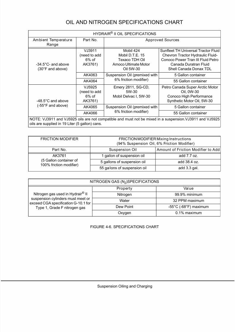
8/17/2019 Ce Aw 004101
http://slidepdf.com/reader/full/ce-aw-004101 129/265

8/17/2019 Ce Aw 004101
http://slidepdf.com/reader/full/ce-aw-004101 130/265

8/17/2019 Ce Aw 004101
http://slidepdf.com/reader/full/ce-aw-004101 131/265
G03027 Front Wheel Hub and Spindle G3-1
TOE-IN ADJUSTMENT
1. Move the truck to a flat, level surface. Align the
front wheels in a straight ahead position and
then turn the key switch to the OFF position.
Allow at least 90 seconds for the steering circuit
to depressurize. DO NOT turn the steering
wheel during this time. After 90 seconds, verify
that the circuit is depressurized by turning the
steering wheel. If the wheels do not turn, the
truck is safe to adjust. Chock the wheels to pre-
vent truck movement.
2. Check the toe-in by measuring the distance
between the centers of the front tires. Refer to
Figure 3-1. Measure along the horizontal cen-
terlines at the front and rear of the front tires.
3. For trucks equipped with radial tires, the mea-
surements at the front and rear of the tires must
be equal. Equal measurements at the front and
rear result in 0 toe-in. If the measurements are
not equal, the tie rod must be adjusted. Proceed
to the next step.
The nominal front measurement for bias ply
tires is 1.9 ± 0.6 (0.75 ± 0.25 in) less than therear measurement. If the measurement is not
within this range, the tie rod must be applied.Proceed to the next step.
4. Loosen the clamp locknuts on the tie rod and
rotate the tie rod as necessary to obtain the cor-
rect toe-in setting. Refer to Table 2 for addi-
tional information.
5. When the adjustment is complete, tighten the
clamp locknuts on the tie rod to 430 N·m (310 ft
lbs).
6. Remove the chocks from the rear wheels.
TOE-IN DATA cm (in.)
Nominal tie-rod length, radial tires.
(Zero toe-in)
349.2
(137.48)
Nominal tie-rod length, bias ply
tires 1.9 mm (0.75 in. toe-in)
349.6
(137.63)
Change in toe-in dimension with
one full turn of tie rod
2.0
(0.79)
FIGURE 3-1 MEASURING TOE-IN

8/17/2019 Ce Aw 004101
http://slidepdf.com/reader/full/ce-aw-004101 132/265
G3-2 Front Wheel Hub and Spindle G03027
NOTES

8/17/2019 Ce Aw 004101
http://slidepdf.com/reader/full/ce-aw-004101 133/265
Automatic Lubrication System
AUTOMATIC LUBRICATION SYSTEM
LUBRICANT REQUIRED FOR SYSTEM
Grease requirements will depend on ambient tem-
peratures encountered during truck operation:
• Above 32°C (90°F) - Use NLGI No.2multipurpose grease (MPG).
• -32° to 32°C (-25° to 90°F) - Use NLGI No. 1multipurpose grease (MPG).
• Below -32°C (-25°F) - Refer to local supplier for extreme cold weather lubricant requirements.
SYSTEM PRIMING
The system must be full of grease and free of air
pockets to function properly. After maintenance, if
the primary or secondary lubrication lines were
replaced, it will be necessary to prime the system to
eject all entrapped air.
1. Fill lubrication reservoir with lubricant, if neces-
sary.
2. To purge air from the main supply line, remove
the main supply line at outlet port (6, Figure 3-1)
and connect an external grease supply to the
line.
3. Remove plugs from each injector group in
sequence (right front, left front, and rear axle).
4. Using an external grease source, pump grease
until grease appears at the group of injectors
and re-install the pipe plug. Repeat for remain-
ing injector groups.
5. Remove the caps from each injector and con-
nect an external grease supply to the zerk on
the injector and pump until grease appears at
the far end of the individual grease hose or the
joint being greased.
LUBRICANT PUMP
Pump Housing Oil Level
The pump housing must be filled to the proper leve
with SAE 10W30 motor oil. Oil level must be checked
at 1000 hour intervals. To add oil, remove oil leveplug (4, Figure 3-1) and fill the housing to the bottom
of the plug hole.
Pump Pressure Control
High pressure hydraulic fluid from the truck steering
system is reduced to 2240 to 2413 kPa (325 to 350
psi) by the pressure reducing valve located on the
manifold on top of the pump motor. This pressure
can be read on the gauge installed on the manifold
and must be checked occasionally to verify pressure
is within the above limits.
FIGURE 3-1. PUMP CONTROLS
1. Pump Pressure
Control
2. Manifold
3. Pressure Gauge
4. Oil Level Plug
5. Flow Control Valve
6. Outlet Port
7. Manual Override

8/17/2019 Ce Aw 004101
http://slidepdf.com/reader/full/ce-aw-004101 134/265
Automatic Lubrication System
INJECTORS (SL-1 Series H)
Injector Specifications
• Each lubrication injector services only onegrease point. In case of pump malfunction, eachinjector is equipped with a covered grease fittingto allow the use of external lubricatingequipment.
• Injector Output Volume:
Maximum Output =1.31 cc (0.08 in3)
Minimum Output = 0.13 cc (0.008 in3)
• Operating Pressure:Minimum - 12755 kPa (1850 psi)Maximum- 24133 kPa (3500 psi)Recommended - 17238 kPa (2500 psi)
• Maximum Vent Pressure (Recharge):4137 kPa (600 psi)
Injector Adjustment
The injectors may be adjusted to supply from 0.13 -1.31 cc (0.008 - 0.08 in3) of lubricant per injection
cycle. The injector piston travel distance determines
the amount of lubricant supplied. This travel is con-
trolled by an adjusting screw in the top of the injector
housing.
Turn adjusting screw (1, Figure 3-2) counterclock-
wise to increase lubricant amount delivered and
clockwise to decrease the lubricant amount.
When the injector is not pressurized, maximum injec-
tor delivery volume is attained by turning adjustingscrew (1) fully counterclockwise until piston assembly
(8) touches the adjusting screw. At the maximumdelivery point, about 9.7 mm (0.38 in.) adjusting screwthreads must be showing. Decrease the delivered
lubricant amount by turning the adjusting screw clock-wise to limit injector piston travel. If only half the lubri-
cant is needed, turn the adjusting screw to the pointwhere about 4.8 mm (0.19 in.) threads are showing.The injector will be set at the minimum delivery point
with about 0.22 mm (0.009 in.) thread showing.
NOTE: The above information concerns adjustment
of injector delivery volume. The timer adjustment
must also be changed if overall lubricant delivery is
too little or too much. Injector output must not beadjusted to less than one-fourth capacity.
NOTE: Piston assembly (8) has a visible indicator pin
at the top of the assembly to verify injector operation
NOTE: Piston stop plug (3) must be tightened to 34-41
N·m (25-30 ft lbs). Adapter (19) must be tightened to
61-68 N·m (45-50 ft lbs).
FIGURE 3-2. TYPE SL-1 INJECTOR
1. Adjusting Screw
2. Locknut
3. Piston Stop Plug
4. Gasket
5. Washer
6. Viton O-Ring
7. Injector Body
Assembly
8. Piston Assembly
9. Fitting Assembly
10. Plunger Spring
11. Spring Seat
12. Plunger
13. Viton Packing
14. Inlet Disc
15. Viton Packing
16. Washer
17. Gasket
18. Adapter Bolt
19. Adapter
20. Viton Packing

8/17/2019 Ce Aw 004101
http://slidepdf.com/reader/full/ce-aw-004101 135/265
Automatic Lubrication System
SYSTEM CHECKOUT
To check system operation, not including the timer,
proceed as follows:
1. Start the engine.
2. Actuate the test switch at the reservoir/pump
assembly.
3. The motor and pump will operate until the sys-
tem attains 20685 kPa (3000 psi).
4. Once the required pressure is achieved, thepump motor will turn off and the system will vent.
5. Check for pump, hose, or injector damage or
leakage when the system is pressurized.
6. After checking the system, shut the engine off.
Observe normal precautions regarding high
voltage present in the propulsion system before
attempting to repair the lubrication system.
Lubrication Cycle Timer CheckTo check the solid-state timer operation without wait-
ing for the normal timer setting, proceed as follows:
NOTE: The timer incorporates a liquid and dust-tight
cover which must be in place and secured at all times
during truck operation.
1. Remove the dust cover.
2. Adjust timer selector (3, Figure 3-4) to the five
minute interval setting.
3. The timer must cycle in five minutes if the truck
is operating.
NOTE: If the timer check is being made on a cold
start, the first cycle will be approximately double the
nominal setting. All subsequent cycles must be within
the selected time tolerance.
4. Perform voltage checks at the timer if the above
checks do not identify the problem.
a. Ensure that the timer ground connection is
clean and tight.
b. With the key switch on, use a voltmeter toread the voltage between the positive andnegative posts on the solid-state timer. A nor-
mal reading must be 18 to 26VDC, depend-ing upon whether the engine is on or not.
.
FIGURE 3-3. LOCATION OF LUBRICATION CYCLE
TIMER1. Cab Interface
Compartment Under
Passenger Seat
2. Lubrication Cycle
Timer
FIGURE 3-4. LUBRICATION CYCLE TIMER
(SHOWN WITH COVER REMOVED)
1. Timer Enclosure
2. Red LED
3. Timer Selector

8/17/2019 Ce Aw 004101
http://slidepdf.com/reader/full/ce-aw-004101 136/265
Automatic Lubrication System
Lubrication Cycle Timer Adjustment
The timer is set at the factory for a nominal 2.5
minute (off time) interval. Dwell time is approximately
75 seconds. A longer interval (off time) is obtained by
turning the timer selector to the desired position.
Set the timer by turning the timer selector to the 2.5
minute setting. Then turn the selector clockwise one
detent at a time to the desired setting, or until themaximum limit of 80 minutes is reached.
NOTE: The timer is a sealed unit. DO NOT attempt to
disassemble it.
PREVENTIVE MAINTENANCE INSPECTION
Use the following maintenance procedures to ensure
proper system operation.
10 Hour Lubri cation System Inspection
1. Check the grease reservoir level.
Inspect the grease level height after each shift
of operation. The grease usage must be consis-
tent from day-to-day operations.
Lack of lubricant usage would indicate an inop-
erative system. Excessive usage would indicate
a broken supply line.
2. Check the filter bypass indicator when fill ing the
reservoir. Replace the element if bypassing.
3. Check all the grease hoses from the SL-1 injec-
tors to the lubrication points.a. Repair or replace all damaged feed line
hoses.
b. Ensure all air is purged and all new feed line
hoses are filled with grease before sending
the truck back into service.
4. Inspect the key lubrication points for a bead of
lubricant around the seal. If a lubrication point
appears dry, troubleshoot and repair the prob-
lem.
100 Hour Inspection
1. Check the oil after every 100 hours of opera-
tion. The crankcase must be filled to the cente
of the drain plug located on the back of the
crankcase.
250 Hour Inspection1. Check all grease hoses from the SL-1 injectors
to the lubrication points.
a. Repair or replace all worn and broken hoses
b. Ensure all the air is purged and all new feed
line hoses are filled with grease before send-
ing the truck back into service.
2. Check all grease supply line hoses from the
pump to the SL-1 injectors.
a. Repair or replace all worn and broken supply
lines.
b. Ensure all air is purged and all new supply
line hoses are filled with grease before send-
ing the truck back into service.
3. Check the grease reservoir level.
a. Fill the reservoir if low. Check the filte
bypass indicator when filling the reservoir
Replace the element if bypassing.
b. Check the reservoir for contaminants. Clean
if required.
c. Check that all filler plugs, covers, and
breather vents on the reservoir are intact and
free of contaminants.
4. Inspect all bearing points for a bead of lubricant
around the bearing seal.
It is good practice to manually lubricate each
bearing point at the grease fitting provided on
each Injector. This will indicate if there are any
frozen or plugged bearings, and will help flush
the bearings of contaminants.
8/17/2019 Ce Aw 004101
http://slidepdf.com/reader/full/ce-aw-004101 137/265
Automatic Lubrication System
5. System Checkout.
a. Remove all SL-1 injector cover caps to allow
visual inspection of the injector cycle indica-
tor pins during system operation.
b. Start the truck engine.
c. Actuate manual override (7, Figure 3-1). The
hydraulic motor and grease pump should
operate.
d. With the system pressurized, check each
SL-1 injector assembly. The cycle indicator
pin will be retracted inside the injector body.
e. When the system attains 20685 kPa (3000
psi), the pump will shut off and the pressure
in the system will drop to zero, venting back
to the grease reservoir.
f. With the system vented, check all of the SL-1
injector indicator pins. All of the pins must be
visible. Replace or repair the injectors, if
defective.g. Reinstall all the injector cover caps.
h. Check the timer operation.
NOTE: With the engine on, the lubrication system will
activate within five minutes. System pressure will
build to 20685 kPa (3000 psi) within 25-40 seconds.
i. If the system is working properly, the
machine is ready for operation.
j. If the system is malfunctioning, refer to thetroubleshooting chart.
500 Hour Inspection
1. Change the oil after every 500 hours of opera-
tion. Use SAE 10W30 motor oil.
1000 Hour Inspection
1. Check the pump housing oil level. Refill to the
bottom of the level plug with SAE 10W30 motooil, if necessary.

8/17/2019 Ce Aw 004101
http://slidepdf.com/reader/full/ce-aw-004101 138/265
Automatic Lubrication System
NOTES

8/17/2019 Ce Aw 004101
http://slidepdf.com/reader/full/ce-aw-004101 139/265

8/17/2019 Ce Aw 004101
http://slidepdf.com/reader/full/ce-aw-004101 140/265
NOTES:
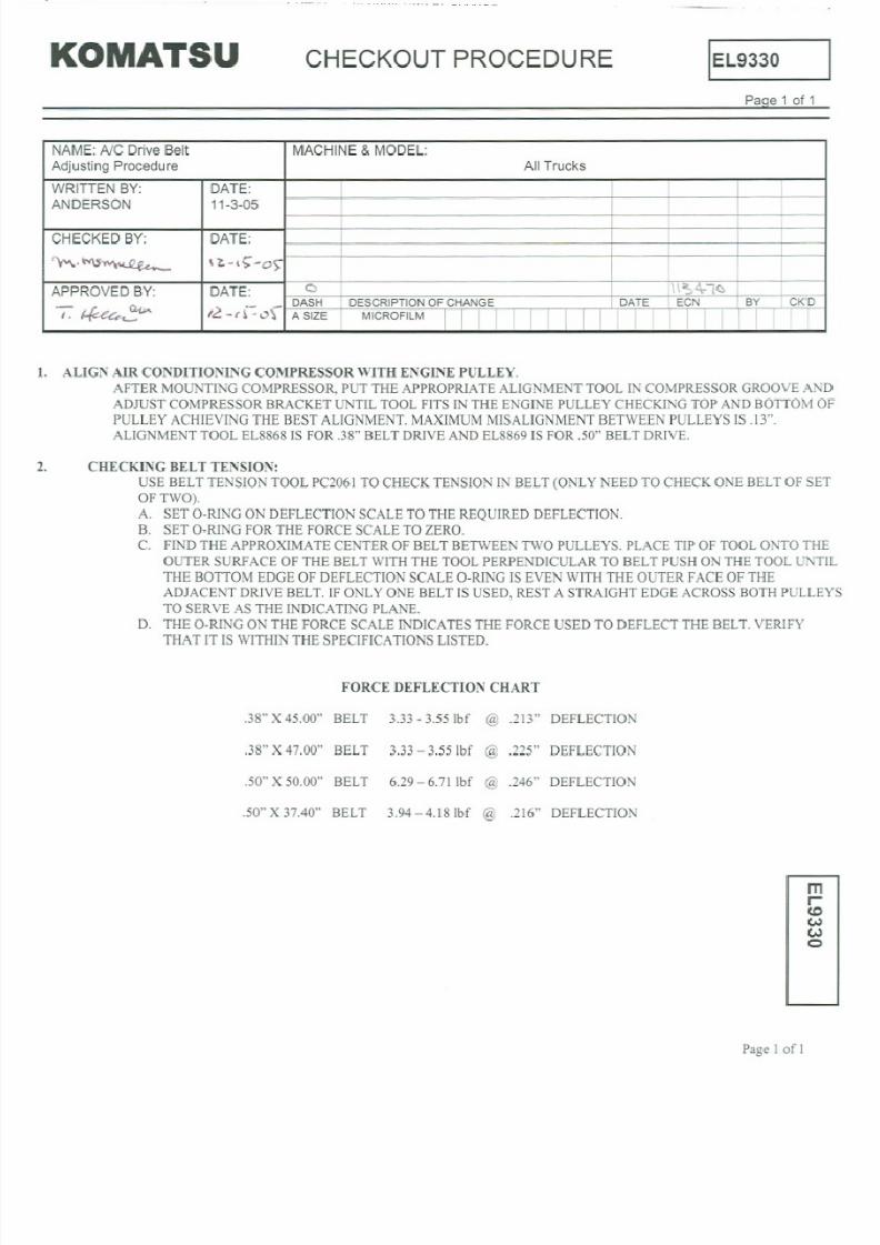
8/17/2019 Ce Aw 004101
http://slidepdf.com/reader/full/ce-aw-004101 141/265

8/17/2019 Ce Aw 004101
http://slidepdf.com/reader/full/ce-aw-004101 142/265
NOTES:

8/17/2019 Ce Aw 004101
http://slidepdf.com/reader/full/ce-aw-004101 143/265

8/17/2019 Ce Aw 004101
http://slidepdf.com/reader/full/ce-aw-004101 144/265
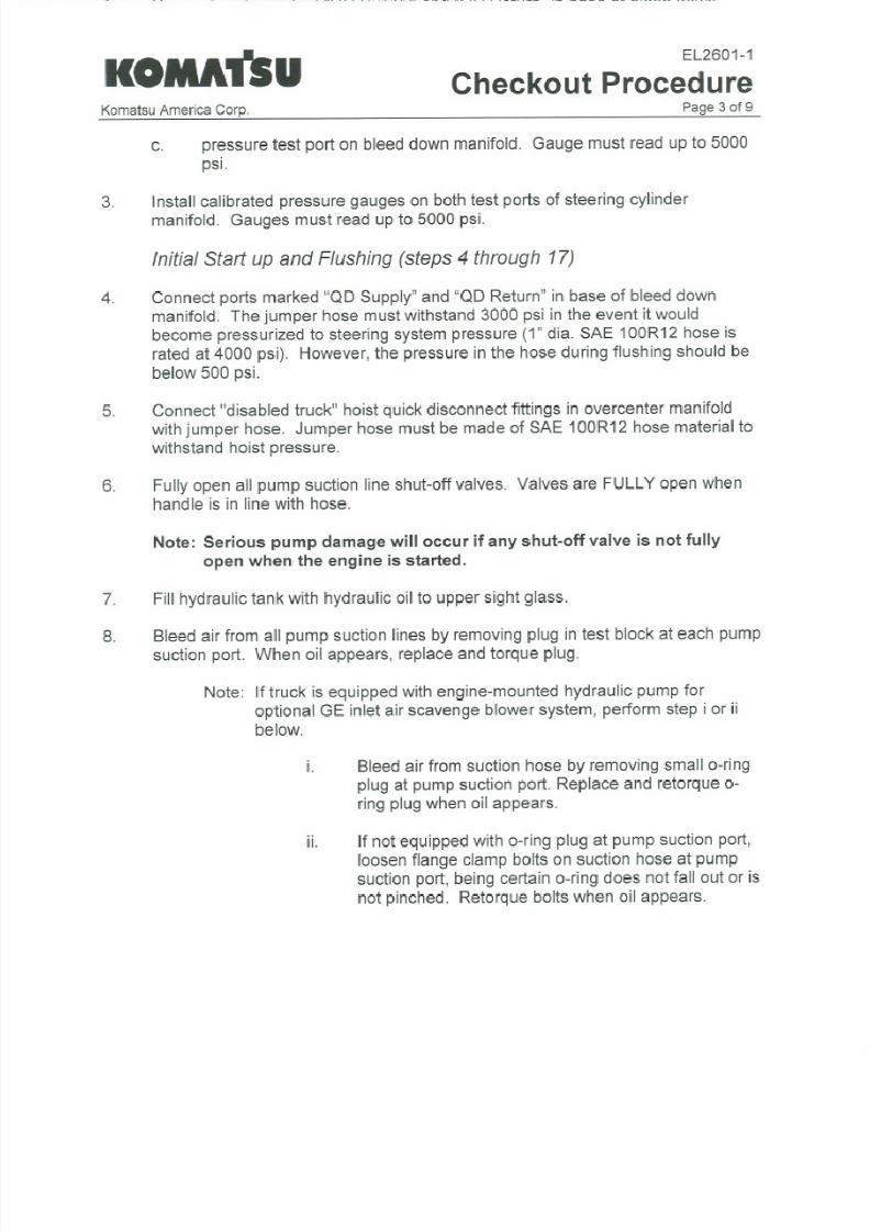
8/17/2019 Ce Aw 004101
http://slidepdf.com/reader/full/ce-aw-004101 145/265

8/17/2019 Ce Aw 004101
http://slidepdf.com/reader/full/ce-aw-004101 146/265

8/17/2019 Ce Aw 004101
http://slidepdf.com/reader/full/ce-aw-004101 147/265
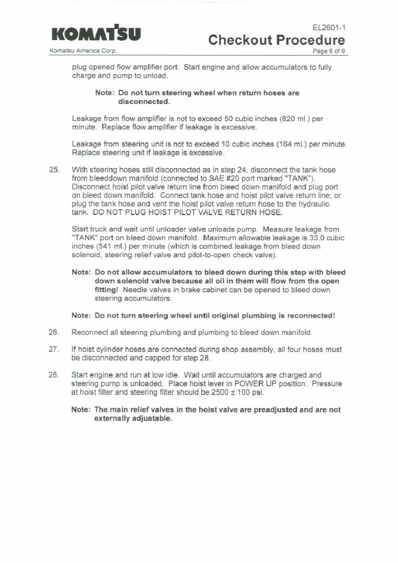
8/17/2019 Ce Aw 004101
http://slidepdf.com/reader/full/ce-aw-004101 148/265

8/17/2019 Ce Aw 004101
http://slidepdf.com/reader/full/ce-aw-004101 149/265

8/17/2019 Ce Aw 004101
http://slidepdf.com/reader/full/ce-aw-004101 150/265

8/17/2019 Ce Aw 004101
http://slidepdf.com/reader/full/ce-aw-004101 151/265

8/17/2019 Ce Aw 004101
http://slidepdf.com/reader/full/ce-aw-004101 152/265
NOTES:

8/17/2019 Ce Aw 004101
http://slidepdf.com/reader/full/ce-aw-004101 153/265
HE K OUT PRO EDURE
L
EF5761
-
'a,- 1 of 7
Necessary Equipment
1. Check-out procedure and systemschematic
2. Accumulator charging outfitwith good gauges and eitherK type bottles of dry
nitrogen or T type bottleswith a gas intensifier.
3. Clear plastic hose and bucket for bleeding brakes of air.
4. If truck is only partially assembled and this check-out is to be donewithout brakes
installed, brake simulators are required in order to simulate the brake volumes.
5. At least 3, calibrated gauges with quick-connect couplings, capable of measuring
up to 5000 psi.
Assumptions
1. All components used within the brake systemare to specification.
2. Any parts that do not function as describedwill be replaced or adjusted. (Notify
Quality Control Department for problemsor to obtain adjusting procedures for
individual components.)
3. The hydraulic source for the brake system (The Steering System is in proper
operation and the compensator has been adjusted.
Note: Refer to steeringand hoist check-out group for procedures and
specifications.
Initial System Set-up
1. Install pressure measuring instruments at:
(a) Test Port BF (brake cabinet)
(b) Test Port BR (brake cabinet)
(c) Test Port LAP1 (brakemanifold)
2. Open each brake accumulator bleed downvalve and precharge both accumulators
to 1400 psi. Allow gas temperature to approachambient temperature before
completing precharge process.
~
0
..
I
671-1-3-97
Komatsu Mining Systems, Inc.
Peoria Operations
+
'aS8 1 of 7
NAME
MACHINE& HODEL
BRAKE SYSTEM CHECKOUT 730E
WRITTEN BY
DATE
I
D. D. Smith
6/20/95
4
PlIrkin2:
Brk Note: P2:2
8 1
OlH
l 00
NS
D-Ddate 1t14 tor Mt2:.
4
14/
10 l'
CHECKED BY
DATE
L
ReVlsed-Steps ::IU & jj
14/ ,ti
1 L:h2: teps
14. 17
LL lJ.,
titi Kt;
0 STR.ASY.p U [O
ON
6
) <
02
2 T
-,,-
n.
tH
DATE
DASH D£SCRIPTIOHOF CMANCiE
DATE
[CN
BY
CK
R. J. McClone
6/26/95
A SIZE1 MICROFILM I I I I I I I I I I I I
I I
I
I I

8/17/2019 Ce Aw 004101
http://slidepdf.com/reader/full/ce-aw-004101 154/265
EF5761
au 2 of 7
HE K OUT PRO EDURE
Note: For best performance, charge accumulators in the ambient conditions in
which the machine will be operating.
3. Close both accumulator bleed downvalves. Ifbrakes have not been assembled to
truck when check-out is performed, attachbrake simulators to the brake
application lines.
*
4. Start engine to fill accumulatorswith oil. Observe risingbrake pressures as
system charges. Brake pressure shouldbegin to fallwhen Auto Apply Valve
releases. The brake pressures when auto apply releases should be approximately
1750psi front and 1700psi rear. Record the brake pressures at auto apply release.
5. Partially depress brake pedal and bleed air frombleeders located at each brake or
brake simulators.
Parking Brake
Note: Move one of the pressuremeasuring instruments from the BF or BR
locations to port PK2 on the brake manifold.
*
6. Apply brake lock. Release parking brakewith park brake switch. Verify that
park brake status light indicates parking brake is released. Record parking brake
release pressure. (pressure shouldbe 2600=t100psi).
*
7. Ifparking brakes are onvehicle, thenmeasure the lining to discclearance with
feeler gauge and record the clearances.
8. Cycle park brake switch several times to assure crisp application and release of
pressure and proper functionof status light.
9. Apply parking brake and release brake lock.
Note: Return the pressure measuringdevice to the BF or BR location.
Service Brakes
10. Very slowly depress brake pedal to check circuit tracking. Rear brake pressure
must begin to rise before front brake pressure. Rear brake pressure should be
between 45 and 205 psi when front brake pressurebegins to rise. Force feedback
of pedal on foot shouldbe smoothwith no abnormalnoise or mechanical
roughness.
*
11. Slowly depress brake pedal and record the rearbrake pressure at which the stop
lights energize. (Thisshouldbe 75=tpsi). . .
Komatsu Mining Systems, Inc.
Peoria Operations
rue of

8/17/2019 Ce Aw 004101
http://slidepdf.com/reader/full/ce-aw-004101 155/265
om tsu
HE K OUT PRO EDURE
EF5761 - 4
au of 7
*
12. Quickly and completely depress pedal and check to see that front brake pressure
is 2500 i: 100psi and that rear brake pressure is 1700i: 75 psi within 1 second.
Holding pedal fully applied, both pressures should remain above their minimum
values for a minimumof 20 seconds.
*
13.Release peda1. Brake pressure shouldreturn to zerowith a couple of seconds and
there should be no residualpressure trapped inbrakes. If the vehicle is equipped
with rear brakes check to see if rear brake linings are retracted frombrake discs
and are free and loose inbrake calipers.
Note: If step 13is incorrect, perform deadbandadjustment as follows: Insert a
O.025 shimbetween valve and pedal return stop. Loosenjam nut. Adjust set
screw until pressure begins to rise in one or both circuits. Back set screw off 1/8
turn and lock set screwwith jam nut. Remove the shim.
Brake Lock/Secondary
14. (A) Disconnect leadwire on brake lock solenoid, located on brake manifold in
hydraulic cabinet and to the immediate right of the PK2 port.
(B) Install jumper to connect delay timer wires together.
15. Apply brake lock. Brake lock pressure degradation switch should sound warning
buzzer. Depress brake pedal until warning stops and then very slowly release
pedal until warning resumes. RecordBR pressure at which warning resumes.
16. Connect leadwire on brake lock solenoidand removejumper from leadwires to
timer.
*
17. Cycle brake lock several times to assurecrisp application of and release of
pressure and proper functionof status light. Record rear brake pressure, which
should be 1500i: 100psi.
Low Brake Pressure and Auto Apply
I
18. Allow engine to run until low brake accumulator pressure stabilizes at or above
2700psi.
*
19. Shut engine down. Allow the steeringaccumulator to bleed completely down.
Disable steering pressure switch fromthe brakewarning circuit by unplugging the
diode between circuits 33 and 33F. (Thisis diode 22 on diode board 1) Turn key
switch on. After 2 minutes record the low accumulator pressure. (LAP1port) If
LAPI pressure is below 2100 psi, then leakage in the system is excessive and the
source of the leakage needs to be identified.
KomatsuMining Systems, Inc.
Peoria Operations
of

8/17/2019 Ce Aw 004101
http://slidepdf.com/reader/full/ce-aw-004101 156/265
om tsu HE K OUT PRO EDURE ( EF5761 ~
e 4
of 7
*
20. Crack the front brake accumulatorbleed down valve and observe LAP1 pressure.
The low brake pressure lampand buzzermust actuate at 1850:: ::5 psi. Record
this value. Brake pressures shouldbegin to rise (auto apply)when LAP1 reaches
1650
100psi. Recordthisvalue. Closefrontbrakeaccumulatorbleeddown
valve.
*
21. Record auto apply brake pressures.
22. Start engine to recharge hydraulic system. Allow e.qgineto run until low brake
accumulator pressure stabilizes at or above 2700 psi.
23. Shut engine down. Allow the steeringaccumulator to bleed completely down.
Turn key switch on. Crack the rear brake accumulatorbleed down valve and
observe LAP1pressure. Verifythat the low brake pressure lampand buzzer, and
auto apply set points are within a 100psi of those recorded in step 20. Close the
rear brake accumulator bleed downvalve.
*
24. Record auto apply brake pressures. Enable the steeringpressure switch by
plugging in the diode removed between circuits 33 and 33F.
Reapplications
25. Start engine to rechargehydraulic system. Allow engine to run until low brake
accumulator pressure stabilizes at or above2700 psi.
*
26. Shut engine down. Do not allow steeringaccumulatorto bleed down. Make
repeated slow, completebrake applicationswith pedal until auto apply comes on.
Record the number of brake applicationsprior to auto apply.
Differential Pressure Switch
27. Open each brake accumulator bleed down valve and bleed down the entire brake
system.
28. Outside the brake cabinet, disconnect the hose that supplies oil from the front
brake accumulator to the brake pedalinthe cab for the front brakes and plug the
tube end at the cabinet. Be sureto leave end of hosevented to atmosphere.
29. Start engine. Allow the engineto run until LAP1pressure stabilizes at or above
2700 psi.
Komatsu Mining Sys~ems, Inc.
Peoria Operations
a 4 of

8/17/2019 Ce Aw 004101
http://slidepdf.com/reader/full/ce-aw-004101 157/265
EF5761
- 4
au 5 of 7
HE K OUT PRO EDURE
30. Very slowly depressthe brake pedaluntil the brake differential switch has
activated the low brake pressurelamp andthe buzzer. Record the rear brake
pressure at the point this occurs. (The fault should occur @ 600 ~ 50 psi).
Release the pedal.
31. Shut engine down and turn
key
switchoff. Openeach brake accumulator bleed
down valve and bleed down entire brake system.
32. Outside the brake cabinet, reconnect the hose that connects the front brake
accumulator to the brake pedal incab. Disconnectthe hose that supplies oil from
the rear brake accumulator to the brake pedal in the cab for the rear brakes and
plug the tube end at the cabinet. Be sure to leave end of hose vented to
atmosphere.
33. Very slowly depress the brake pedal until the rear brake differential switch has
activated the low brake pressure lamp and the buzzer. Record the front brake
pressure at the point this occurs. (The fault should occur at
1O00:: ::
5 psi).
Release the pedal.
. .
34. Shut engine down and turn key switchoff Openeach brake accumulator bleed
down valve and bleed downthe entirebrake system. Outsidethe brake cabinet,
reconnect the hose that connects the rear brake accumulator to.the brake pedal in
cab. Remove all instrumentation and simulators. This concludes the brake
system check-out.
*Asterisk denotes item to be recordedData Sheet.
Komatsu Mining Systems, Inc.
Peoria Operations a 5 of

8/17/2019 Ce Aw 004101
http://slidepdf.com/reader/full/ce-aw-004101 158/265
om tsu
HE K OUT PRO EDURE
I EF5761 ~
Pau of
HYDRAULICBRAKE SYSTEM
CHECK-OUTDATA SHEET
STEP 4
Front brake pressurewhen Auto Apply releases.
Rear brake pressurewhen Auto Apply releases.
PARKING BRAKE SYSTEM
STEP 6
Parking brake releasepressure.
STEP 7
Left outboard lining/discgap.
Left inboard lining/disc gap.
Right outboardlining/discgap.
Right inboard lining/discgap.
SERVICE BRAKE SYSTEM
STEP 11
Rear brake pressurewhen stop lights energize.
STEP 12
Front brake pressure. pedal applied
Rear brake pressure pedalapplied
STEP 13
Front brake pressure pedal released
Rear brake pressure pedal released
Komatsu Mining Systems, Inc.
Peoria Operations
.
Pau of
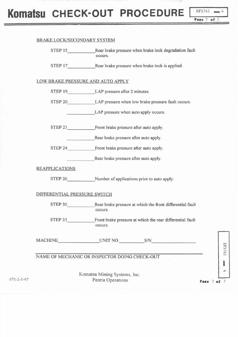
8/17/2019 Ce Aw 004101
http://slidepdf.com/reader/full/ce-aw-004101 159/265
om tsu HE K OUT PRO EDURE
EF5761
-
4
P..e 7 of 7
BRAKE LOCK/SECONDARY SYSTEM
Rear brake pressurewhen brake lock degradation fault
occurs.
STEP 15
Rear brake pressurewhen brake lock is applied.
TEP 17
LOW BRAKE PRESSUREAND AUTOAPPLY
LAP pressure after 2 minutes.
TEP 19
LAP pressurewhen low brake pressure fault occurs.
TEP 20
LAP pressurewhen auto applyoccurs.
STEP 21
Front brake pressure after auto apply.
Rear brake pressure after auto apply.
STEP 24
Front brake pressureafter auto apply.
Rear brake pressureafter auto apply.
REAPPLICATIONS
STEP 26
Number of applicationsprior to auto apply.
DIFFERENTIAL PRESSURE SWITCH
STEP 30
Rear brake pressure at which the front differential fault
occurs.
STEP 33
Front brake pressure at which the rear differential fault
occurs.
MACHINE
UNITNO.
SIN
NAME OFMECHANIC OR INSPECTORDOINGCHECK-OUT
Komatsu Mining Systems, Inc.
Peoria Operations
Pau 7 of

8/17/2019 Ce Aw 004101
http://slidepdf.com/reader/full/ce-aw-004101 160/265
NOTES:

8/17/2019 Ce Aw 004101
http://slidepdf.com/reader/full/ce-aw-004101 161/265
OM TSU CHECKOUT PROCEDURE
I EK8480-1
Paqe 1 of 15
Structure and purpose:
This procedure is in two parts. The first part verifiesthe installationof the VHMScontroller,The
Interface module, the OrbCommcommunicator, the sensors, and all associated wiring.
The second partofthe proceduresetsupVHMSfortimeof day,timezone,fault,trendand
payloaddata transmission,andOrbCommcommunicationsettings.
Preliminarv procedures (can be done before ac~nstallationt
1. WebCARE Machine registrationmust be completed. Fill out the WebCARE Machine
registration request (a copy is attached to this document) and FAX to the
VHMSlWebCARE support team (FAX number is on the form).
2. The Orbcomm activation request must becompleted (a copy is also attached to this
document). If this is a field installation, one of the serial number stickers should be
placed on the form (be sure to place the other on the Orbcomm modem itself). When
complete, FAX the form to the KOMTRAXService Hotline (FAX number is on the form).
Itwill take a week or two to complete this activation.
Necessarv
Eauipment:
1. Checkout procedure and system schematic.
2. Laptop computer with VHMS PC software installed VHMS Technical Analysis
Toolbox , and VHMS Watcher software.
RS232 serial cable with a male DB9connector on one end and a female connector
on the other end.
You will need the correctCGCDatcsv file for use with the specific truck model you
are checking out This .csv file is used with the VHMS Watcher software to identify
by name the input signals that the Interface Module (1M)sends to VHMS.
3.
4.
Installina the CGCDat.csv File:
1. The file
names take this form: CGCDat930E.csv, CGCDat830E.csv, etc. They
will be found in the same file folder as the VhmsWatcher.exe program.
The activefile is always named CGCDatcsv. If you have the wrong file active,
you must rename it (OLDCGCDatcsv). Then make a copy of the correct file
and change the copy's name to CGCDatcsv.
2.
Page
1 of 15
m
CO
~
CO
C
I
~
NAME:
MACHINE MODEL:
VHMS System Checkout Procedure
930E, 960E, 830E
WRITTEN BY: DATE:
07/17/04
CHECKED BY: DATE:
1 INTEGRATEDNTERFACEMODULECHECKOUT 8/18/04
\\\ \4
GGH SK
APPROVED BY: DATE:
0
NEWRELEASE
G. Horst
DASH
DESCRIPTIONOFCHANGE
DATE ECN BY
CK
A SIZE MICROFILM
I I I I I I I I I I I I I I I I I I I

8/17/2019 Ce Aw 004101
http://slidepdf.com/reader/full/ce-aw-004101 162/265
OM TSU CHECKOUT PROCEDURE
I
EK8480 1
PaQe2 of 15
INSTALL THE APPLICATION CODE
Before the Interface Module can be put to work, the application code must be installed.
Application code must match the truck model for Interface Module installation.
Use EJ9098 1 software for 930E trucks and EL0355-0 software for 830E trucks.
Go to the Interface Module web site www.kac-peoria.com/interfacemodule/ to get the
necessary files and instructions.
PLM3 NOTE
Use the Payload Data Manager software to verify the PLM3 installed software.
PLM3 software EJ0575-3or later is required for the Interface Module to properly acquire
truck speed on model 830E and 930E trucks. Go to PLM3 web site,
www.kac peoria.com
navload for software and instructions.
PART 1 - Installation and wirin :l verification
CHECK FOR FAULT CODES ASSOCIATED WITH THE INTERFACE
MODULE
Look at a recent download with the VHMS Technical Analysis Toolbox) and view fault history.
Confirm that there are no fault codes associated with the Interface Module. If any are found, these
circuits should be analyzed to determine the cause of the fault and should be repaired.
CHECK INPUT TO THE INTERFACE MODULE
Use the VHMS Watcher software.
1. Double click the shortcut VHMSWatcher on the Desktop screen. The program begins with a
blank window. On the menu bar, there are five items: File, VHMS, Settings, Interaction, Help.
Only use the VHMS pull down menu.
2. Click on VHMS on the menu bar. A small menu pops up, showing two items: Read Table
Data and Port Setting. Click Read Table Data.
3. Click VHMS on menu bar again, this time click Port Setting. A small window shows up to
allow selection of Port Setting. Select the appropriate port COM1,COM2), and select the
baud rate to be 19.2K.
4. Click VHMS on menu bar again. Click Open Connection.
5. Click VHMS on menu bar again, click Start. A window will open as shown:
Page 2 of 15
m
CO
~
CO
Q
I
~
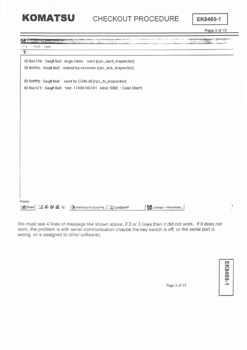
8/17/2019 Ce Aw 004101
http://slidepdf.com/reader/full/ce-aw-004101 163/265
OM TSU CHECKOUT PROCEDURE
I EK8480-1
PaQe 3 of 15
_~r012~:::~~~i~~{~~ '.:~-':::~ :=:~~ ~ - ~'~~'~- :t:s'$~~1:: :7~='~' '
::;:'2 ..HMS :ielp
; If
IDOxc120:Seq# Ox2:Args Hello sent (rpc_senUnspector)
IDOxfffe: Seq# Ox2: acked by receiver (rpc_ack_inspector)
IDOxfffd: Seq# OxO: sentto COM.dll (rpc_tx_inspector)
IDOxc121: Seq#OxO: Ver.11030100181 kind.930E: Cold Start
Ready
fi ltart I; : :iI~
t) lJ
I~~
Interface Module Re. ..1
J;J
Can8anFF J ~
Untitled
-VhmsWatc...1
We must see 4 lines of message like shown above, if 2 or 3 lines then it did not work. If it does not
work, the problem is with serial communication maybe the key switch is off, or the serial port is
wrong, or is assigned to other software .
Page 3 of 15
m
CO
or:.
CO
Q
I
~
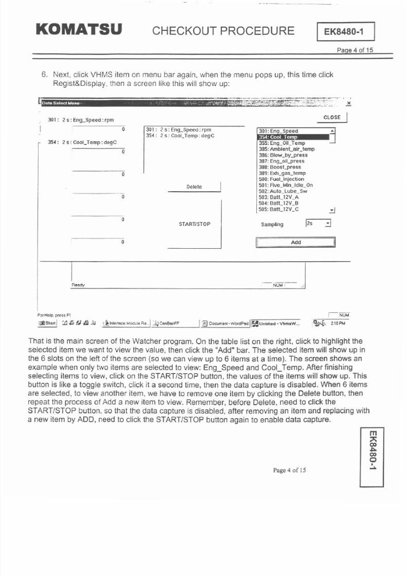
8/17/2019 Ce Aw 004101
http://slidepdf.com/reader/full/ce-aw-004101 164/265
CHECKOUT PROCEDURE
I EK8480-1
Paqe4 of 15
6. Next, click VHMS item on menu bar again, when the menu pops up, this time click
Regist Display, then a screen like this will show up:
Iii
BtaSelectMenu ., ,,'; :-'.;:.';' -;;:~;<i,-::'<:',:' ,~ '~'Hl~ ;.. ,,,~:.--
OM TSU
301: 2s: En9-Speed: rpm
CLOSE I
0
301: 2 s: Eng_Speed: rpm
354: 2 s: Cool_Temp:degC
354: 2 s: Cool_Temp: degC
Delete
355:Eng_OilJemp
385:AmblenCair_temp
386:Blow_by-press
387:Eng_oil-press
388:Boost-press
389:Exh_gas_temp
500:FueUnjection
501:Ave_Min_ldle_On
502:Auto_Lube_Sw
503:BatC 12V_A
504:BatU 2V_B
505:BatU 2V- C
0
0
0
START/STOP
~
12s .:J
ll ~_. ---J
Sampling
0
0
Rel .dy
:J
ForHelp. press F1
::EllStart I : I ~
t1 JJ . r,
~
Interll .ce Module Reml JJ CanBI .nFF
j @ Document. . WordPl .d
I
r~ Untitled - VhmsW...
I;NUM
I~~; 2:10PM
That is the main screen of the Watcher program.On the table list on the right, click to highlight the
selected item we want to view the value, then click the Add bar. The selected item will show up in
the 6 slots on the left of the screen (so we can view up to 6 items at a time). The screen shows an
example when only two items are selected to view: Eng_Speed and CooLTemp. After finishing
selecting items to view, click on the START/STOPbutton, the values of the items will show up. This
button is like a toggle switch, click it a second time, then the data capture is disabled. When6 items
are selected, to view another item, we have to remove one item by clicking the Delete button, then
repeat the process of Add a new item to view. Remember, before Delete, need to click the
START/STOP button, so that the data capture is disabled, after removing an item and replacingwith
a new item by ADD, need to click the START/STOP button again to enable data capture.
Page 4 of IS
m
CO
~
CO
0
I
...
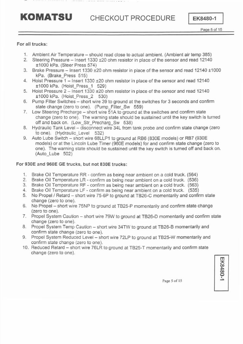
8/17/2019 Ce Aw 004101
http://slidepdf.com/reader/full/ce-aw-004101 165/265
OM TSU
CHECKOUT PROCEDURE
I EK8480 1
PaQe 5 of 15
For all trucks:
1. Ambient Air Temperature - should read close to actual ambient. Ambient air temp 385
2. Steering Pressure - Insert 1330 :t20 ohm resistor in place of the sensor and read 12140
:t1000
kPa. Steer Press 574
3. BrakePressure- Insert1330:t20 ohm resistor in place of the sensor and read 12140 :t1000
kPa. Brake_Press 515
4. HoistPressure1- Insert1330
:t20 ohm resistor in place of the sensor and read 12140
:t1000 kPa. Hoist_Press_1 529
5. Hoist Pressure 2 - Insert 1330 :1:20ohm resistor in place of the sensor and read
12140
:t1000
kPa. Hoist_Press_2 530
6. Pump Filter Switches - short wire 39 to ground at the switches for 3 seconds and confirm
state change zero to one . Pump_Filter_Sw 559
7. Low Steering Precharge - short wire 51A to ground at the switches and confirm state
change zero to one . The warning state should be sustained until the key switch is turned
off and backon. Low_Str_Precharg_Sw 538
8. Hydraulic Tank Level- disconnect wire 34L from tank probe and confirm state change zero
to one . Hydraulic_Level 532
9. Auto Lube Switch - short wire 68LLP1 to ground at RB6 830E models or RB7 930E
models or at the Lincoln LubeTimer 960Emodels for and confirm state change zero to
one . The warning state should besustained until the key switch is turned off and back on.
Auto_Lube 502
For 930E
and
960E GE
trucks but not 830E trucks:
1. Brake Oil Temperature RR
-
confirm as being near ambient on a cold truck. 564
2. Brake Oil Temperature LR - confirm as being near ambient on a cold truck. 536
3. Brake Oil Temperature RF
-
confirm as being nearambient on a cold truck. 563
4. Brake Oil Temperature LF - confirm as being near ambient on a cold truck. 535
5. No Propel/Retard - short wire 75-6P to ground at TB26-C momentarily and confirm state
change zero to one .
6. No Propel - short wire 75NP to ground at TB25-P momentarily and confirm state change
zero to one .
7. Propel System Caution - short wire 79W to ground at TB26-D momentarily and confirm state
change zero to one .
8. Propel System Temp Caution
-
short wire 34TW to ground at TB26-B momentarily and
confirm state change zero to one .
9. Propel System Reduced Level - short wire 72LP to ground at TB25-W momentarily and
confirm state change zero to one .
10. Reduced Retard- shortwire 76LR to groundat TB25-T momentarily and confirm state
change zero to one .
Page 5 of 15
m
;:
CO
~
CO
Q
I
~
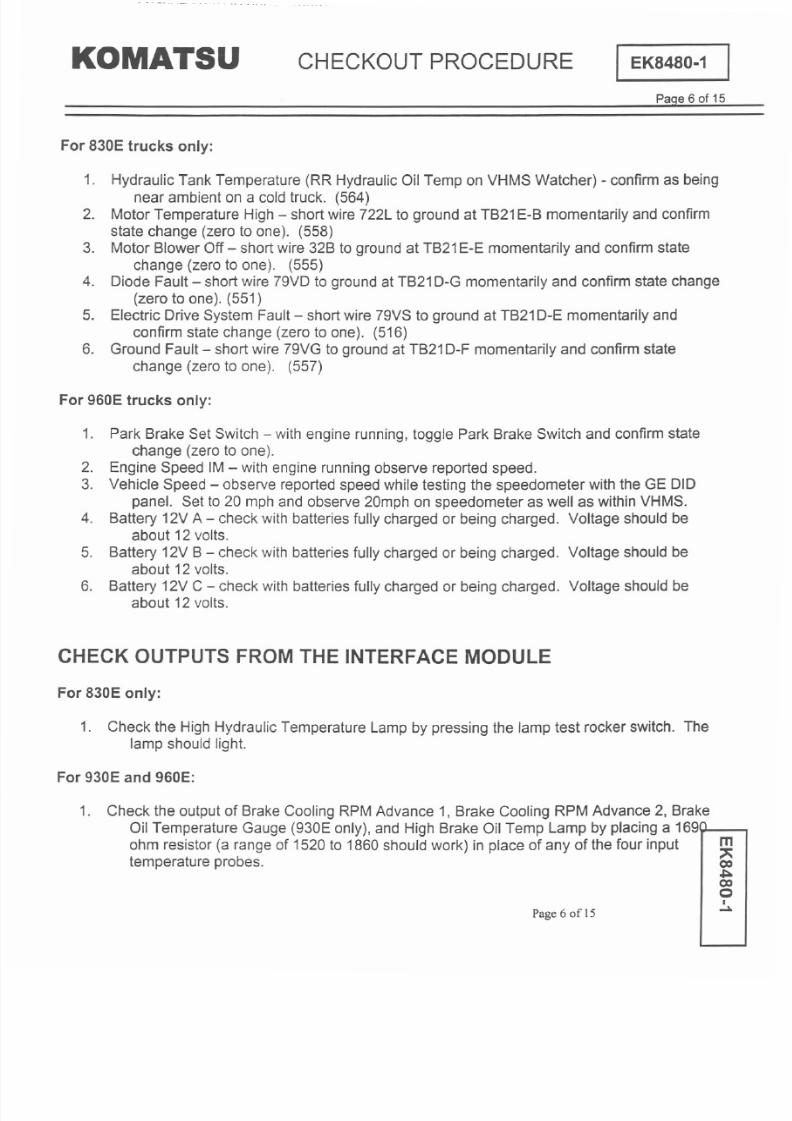
8/17/2019 Ce Aw 004101
http://slidepdf.com/reader/full/ce-aw-004101 166/265

8/17/2019 Ce Aw 004101
http://slidepdf.com/reader/full/ce-aw-004101 167/265
~~~ ~ ~
~ ~
OM TSU
CHECKOUT PROCEDURE
I EK8480 1
PaQe 7 of 15
2. Brake Cooling RPM Advance 1 should go to 24 volts check at TB40-B).
3. Brake Cooling RPM Advance 2 should go to 24 volts check at TB40-C).
4. The Brake Oil Temperature Gauge 930E only) should read near the middle of the red band.
5. The High Brake Oil Temp light should come on.
6. If the output functions do not turn on, read the value of the temperature for the selected input
in VHMS Watcher. It should be between 126 and 140 C.
7. If the temperature reading is low check wiring for high resistance between the probe and
Interface Module.
8. If the temperature reading is high check for shorts in the wiring.
9. It the temperature is in the right range but the output functions do not work, check the
Interface Module output circuit and wiring associated with any non-working function.
For 960E only:
Actuate and hold the lamp test switch in the operator s cab. The following lamps are driven by
the Interface Module and should come on along with all the other lamps):
1. Park Brake Lamp
2. Low Fuel Lamp
3. Batt Charge Alt Failure Lamp
4. 1MWarning Lamp
5. High Brake Oil Temp Lamp
The functionality of the Fuel Level output can be confirmed by observing the needle position of the
gauge when the low fuel lamp comes on.
1. Dismount the sending unit only from the tank and position the gauge to a low level with a
screwdriver. The shaft of the screwdriver will turn this magnetically coupled sending unit
to any position you desire.
2. Set the gauge to empty. After 15 seconds, the Low Fuel Light should come on.
3. Return the gauge to the approximateposition of the actual fuel in the tank before remounting
it.
The Park Brake Solenoid and Brake Apply output can be checked with the following procedure.
1. Turn parking brake off. Park brake valve should be energized and brake auto apply valve
should not. Energizationof these valves can be determined by checking voltage across
the valves or check for magnetism in the valve with a screwdriver.
2. Use the GE DID panel to set the truck speed to some elevated value such as is used to
calibrate the speedometer. The park brake valve should continue to be energized. The
auto apply valve should continue to be off.
3. With the truck speed signal still high, turn the park brake on. The park brake valve should
continue to be energized, and the auto apply valve should stay off.
Page 7 of 15
m
CO
~
CO
Q
.
~

8/17/2019 Ce Aw 004101
http://slidepdf.com/reader/full/ce-aw-004101 168/265
OM TSU
CHECKOUT PROCEDURE
I EK848 1
PaQe
8 of 15
4 Now remove the high truck speed signal The auto apply valve should pulse on for about 1 5
seconds and the park brake valve should turn off after the auto apply valve has been on
for 1 second
Page 8of 15
m
00
~
00
Q

8/17/2019 Ce Aw 004101
http://slidepdf.com/reader/full/ce-aw-004101 169/265
OM TSU
CHECKOUT PROCEDURE
I EK8480-1
Paqe 9 of 15
PART 2
-
VHMS setup
VHMS
Checkout
and WebCARE ReQistration
1. It is vitally important that each item in the checkout procedure be checked-off before continuing
on to the next.
2. The information recorded in form 3 at the back of this procedure will be needed for full
registration and commissionof VHMS. After completion of the form 3, Fax to the number
indicated on the form.
3. Email [email protected]
BeQin
VHMS
Checkout and Setup
Key Switch
off
1. Record the the following on Form 3:
a. Truck serial number (item 2).
b. VHMS box serial number (item 3).
c. OrbComm box serial number (item4).
2. Verify the seven segment LEDdisplay on the VHMS controller are off.
3. Disconnect the OrbCommantenna. (WebCAREmust be ready to receive data before
connecting the antenna.)
KeySwitch on. DO NOT START
Engine.
4. Watch the seven segment red LED display on the VHMS box. After a short time the display
should start counting up. Verify and record (item 5) on Form 3.
5. Connect a lap top PC to the VHMS RS232 serial port.
6. Start the VHMS Setting Tool software.
7. Type the VHMS part number into the Service 10 field. (If VHMS has test software installed
enter 0 .
8. Select Data Clear Setup
9. Select EDIT and set the VHMS time of day clock.
a. Fill in all entries in item 6 on Form 3.
b. Enter the correct time zone. (the UTCor GMT setting)
c. Select DST (Daylight Savings Time) if appropriate)
10.Set the truck model,type, variation, and serial number. Fill in all entries in item 7 on Form3.
11.Set the engine serial numberand record in item 8 on Form 3.
12.Select Apply , accept the confirmation prompts, select no to the download data question and
then select Exit . Completely exit the SettingTool program. Check YES to reboot the
controller.
13.Restart the Setting Tool program.
14.Before entering the Service 10,activate the TEST mode by holding down the ALT key and
typing 'TEST . The heading TEST should appear at the top of 10screen.
15.Enter the Service 10field as in step 7 above.
Page 9 of 15
m
QC
~
QC
Q
I
~
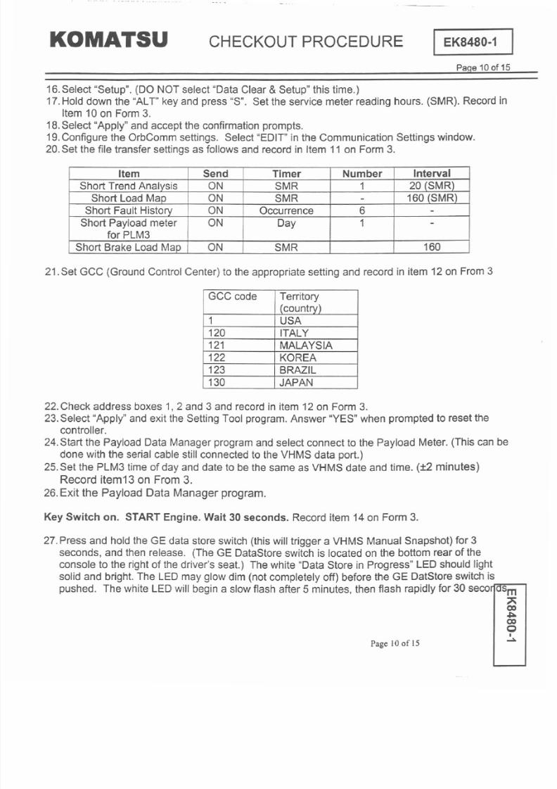
8/17/2019 Ce Aw 004101
http://slidepdf.com/reader/full/ce-aw-004101 170/265
OM TSU CHECKOUT PROCEDURE
I
EK8480-1
PaQe 10 of 15
16.Select Setup . (DO NOT select Data Clear Setup this time.)
17.Hold down the ALT key and press S . Set the service meter reading hours. (SMR). Record in
Item 10 on Form 3.
18.Select Apply and accept the confirmation prompts.
19.Configure the OrbComm settings. Select EDIT in the Communication Settingswindow.
20.Set the file transfer settings as follows and record in Item 11 on Form3.
21.Set GCC (Ground Control Center) to the appropriate setting and record in item 12on From3
22.Check address boxes 1, 2 and 3 and record in item 12on Form 3.
23.Select Apply and exit the Setting Tool program.Answer YES when prompted to reset the
controller.
24.Start the Payload Data Manager program and select connect to the Payload Meter. (This can be
done with the serial cable still connected to the VHMS data port.)
25.Set the PLM3 time of day and date to be the same as VHMS date and time.
:t2
minutes)
Record item13 on From 3.
26.Exit the Payload Data Manager program.
Key Switch
on. START Engine.
Wait
30 seconds. Record item 14 on Form 3.
27.Press and hold the GE data store switch (thiswill trigger a VHMS Manual Snapshot) for 3
seconds, and then release. (The GE DataStoreswitch is located on the bottom rear of the
console to the right of the driver's seat.) The white Data Store in Progress LED should light
solid and bright. The LED may glow dim (not completely off) before the GE DatStore switch is
pushed. The white LEDwill begin a slow flash after 5 minutes, then flash rapidly for 30 secorJOSm
~
co
~
co
Q
I
Page 10of 15
Item en Timer
Number Interval
Short Trend Analysis
ON SMR 1
20 (SMR)
Short LoadMap
ON
SMR
-
160 (SMR)
ShortFaultHistory
ON
Occurrence 6
-
ShortPayloadmeter
ON
Day
1
-
for PLM3
Short Brake Load Map
ON
SMR
160
GCC code
Territory
(country)
1 USA
120 ITALY
121
MALAYSIA
122
KOREA
123
BRAZIL
130
JAPAN

8/17/2019 Ce Aw 004101
http://slidepdf.com/reader/full/ce-aw-004101 171/265
u u
OM TSU
CHECKOUT PROCEDURE
I
EK8480 1
Paqe 11 of 15
beginning at 7 minutes. Record properoperation of the manual data store in item 15on Form3
28.Wait until the DataStore in ProgressLED has finished flashing. Wait another minute, then turn
the key switch off and stop the engine. Recorditem 17 on Form 3.
Key Switch on. DO NOT START Engine. Record item 18on Form 3.
29.Start the VHMS Technical Analysis Tool Box program. (user name = 'usr' and password= '1')
30.Select the Download icon and select the correct comm portwhen prompted, usually COM1.
31.Select Connection
32.Verify that the date time displayed on the download screen are correct for the current local
date/time and that the displayed Service Meter hours are equal to the value entered previously.
Record in item 19 Form3.
33.Verify that a ManualSnapshot (MFAO)has been recorded. The display should showan item
named 'Snapshot' with code MFAOand text Manual Trigger . Record in item 20 on Form3.
34.Select the 'Select All' option (from the bottom right of window) and perform a download. Record
in item 21 on Form3.
35.Verify that the 'Download Completed'message is displayed. Click on exit . Record item22 on
Form 3.
36.From the Technical Analysis Tool Box launchthe View program.
37.Find the data from the download performed in step 31. The data can be identified by the file
name which has the date inwhich it was created. Select the correct file and click OK .
38.Verify that a Manual Snapshot (MFAO)was recorded by selecting Fault History on the upper
left corner of the screen. The MFAOfault should be recorded with the time of the manual
snapshot and SMR hours entered previously.
39.Select the MACHINE HISTORY option from the list on the left side of the screen.
40.Verify that the Key ON/OFF and Engine ON/OFF records are recorded correctly.
41.Exit the V MS Technical nalysis Toolboxsoftware. Record in item 23 on Form 3.
42.Start the Setting Tool program. Enter the Service ID field as in step 7 above.
43.Select the radio button labeled 'Setup and Clear'.
44.Accept all the current settings, then Apply and Exit. Record in item 24 on Form 3.
45.Record remaining items on Form3 and Fax a copy of Form3 to VHMS/WebCARE support
center FAX: 81-3-5561-4766.
46. Email a copy of the download files to VHMSlWebCARE supoort center
[email protected]. The files are found in folder C:\VHMS_DATA\930E\(truck serial
number)\(date of download)\CHKOO01
47.Wait 24 hours. Reconnect the antenna.
Page II ofl5
m
CO
~
CO
Q
I
~

8/17/2019 Ce Aw 004101
http://slidepdf.com/reader/full/ce-aw-004101 172/265
OM TSU
HE KOUT PRO E URE
I EK8480-1
PaQe 12 of 15
To : VHMSlWebCARE support team
FAX: 81-3-5561-4766
Ref. No.
Date
Name
WebCARE machine registration request
Fonn An
DB information]
1. Distributor name
2. Branch Name
3. Person in Charge
4. E-mail address
5. DB code GCPS)
[ Customer information]
6. Customer name 7. Site name
[ Orbcomm Activation]
12. Date of Orbcomm activation
[ Remark]
WebC ARE
VHMS/WebCARE Support team
TEL 81-3-5561-2765
FAX 81-3-5561-4766
E-mail [email protected]
1
.
~
)
Page 12of 15
.
)
-)
I
~
[ Machine information]
8. Model Name 9. Serial No.
10. Unit No.
11. Item to be registered in WebCARE.
VHMS PM Clinic
D
KUC
D
.
Installed on new machine
0
. Retro-klt
0

8/17/2019 Ce Aw 004101
http://slidepdf.com/reader/full/ce-aw-004101 173/265
OM TSU CHECKOUT PROCEDURE
I EK8480-1
Paqe
13 of 15
TO: Customer support Gr.,SolutionDiv.,Komatsu Ltd.
(KOMTRAX Service Hotline)
Phone: +81-463-22-8780
Fax: +81-463-22-8448
Address: 3-25-1 Shinomiya, Hiratsuka-shi, kanagawa254-
8555,Japan
E-mail: [email protected]
I Important
Request for Orbcomm Terminal Activation
Please fill in the form below and fax or send by mail to Customer Support Gr., Kltd. to activate
Orbcomm terminal.
Note:
It will take one or two weeks to activate after being received this sheet.
Orbcomm terminal is unable to communicate before activation being completed.
Page 13of 15
m
CO
~
CO
Q
I
~
Terminal
Terminal Part Number
Pleasefillin terminalPIN S Nor put onenclosedstickerhere)
Terminal S N PIN: S N
Terminal Activation Date
(YY/MM/DD)
Country where used
Machine Information
Model-Type-S/N
Customer s Contact Address
Company (or Plant)
Phone Number
Country-Area-number>
FAXNumber
Country.Area-number)
e-mail address
Name (please print)
First MiddleFamily
Signature
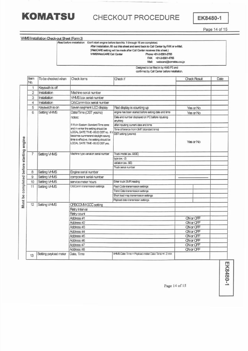
8/17/2019 Ce Aw 004101
http://slidepdf.com/reader/full/ce-aw-004101 174/265

8/17/2019 Ce Aw 004101
http://slidepdf.com/reader/full/ce-aw-004101 175/265
OM TSU
HE KOUT PRO E URE
I EK8480-1
PaQe 15 of 15
Page 15of 15
m
~
CO
~
CO
Q
I
~
14
KeysWtd1iscmrd
'vHvS 00x
Pm LID keep:;cn.ntirg up
Yesal b
erare isn.nim
15
p ,S if lj I 'T 'E J'I .E I
rvtnJaI &1ap:td sWtdl
keepp.JSI'a:itMnfa 3saxrds a rrae
Yesal b
s td
16 OJid<fJII..1
aid< PMpa:aire a dd.nii<r6 pa:aiJes a dd.rciiCJ1St eata stepsa ke :i
CI
17
KeysWtdl df
'vHvS 00x
1..8)v.ei ctf
Yesa I'b
c
'2 18
Key sWtd1 01
'vHvS00x 1..8) sta1s cn.rtiflj t..p Yes
a
I'b
c
19
PC IXMticaj IXMticaj
start
tirre
ra:xrda' <iMtiea: tirre is <XJT tII
Yesa I'b
s
...
GI
:;n
PC IXMticaj
IXMticaj file a:Ilterts
SetIirYJSa cara:t, seNa rreter n rs is cara:t,
Yesa I'b
I'T'EJ'I.EI (M=PQ)isrec:rrcB:t
'51
c
21 PC IXMticaj IXMticaj fileselediro
sawed allfiles
Yes
a
I'b
GI
22 PC IXMticaj
IXMticaj cx:rrpete
S..a:es5fij1y:rrpeta1' rre:ssg;
Yes
a
I'b
'j
PC IXMticaj
IXMticaj data vieN
Mn..a (M=PD)srec:rrcB:tnfaJt tistay,
GI
aid< PMdciain fileis cara:t, Keycricifa d
Yesa I'b
23
0
ergne cricifreards sa savedinrm:tine tistayfile.
C
GI
.c
settirg'vHvS Mm:Iy dear
allfilessa deaa:l SIErsaediflj
PW /
indEB ITB'IJ
>- 24
Yesal b
III
ct
PCtaj.
::E
25 KeysWtdl isdf
'vHvS 00x
I..8Jsctf
Yesa I'b
26
O:w ID.vica:Idciafiles
ro;Jf fran direday
seIedaj theIciest<iMtiea: datadrectay
Yesal b
27
Tra1SI1it IifljQ:ia to Selediflj files to 'pea: to
sarooo allfiles
Yes
a
I'b
2B
Tra1SI1itIiflj Q:ia to
l.,\jcaj cx:rrpeie
S..a:es5fijlya:rrpeta1' rre:ssg;
Yesa I'b

8/17/2019 Ce Aw 004101
http://slidepdf.com/reader/full/ce-aw-004101 176/265
NOTES:

8/17/2019 Ce Aw 004101
http://slidepdf.com/reader/full/ce-aw-004101 177/265
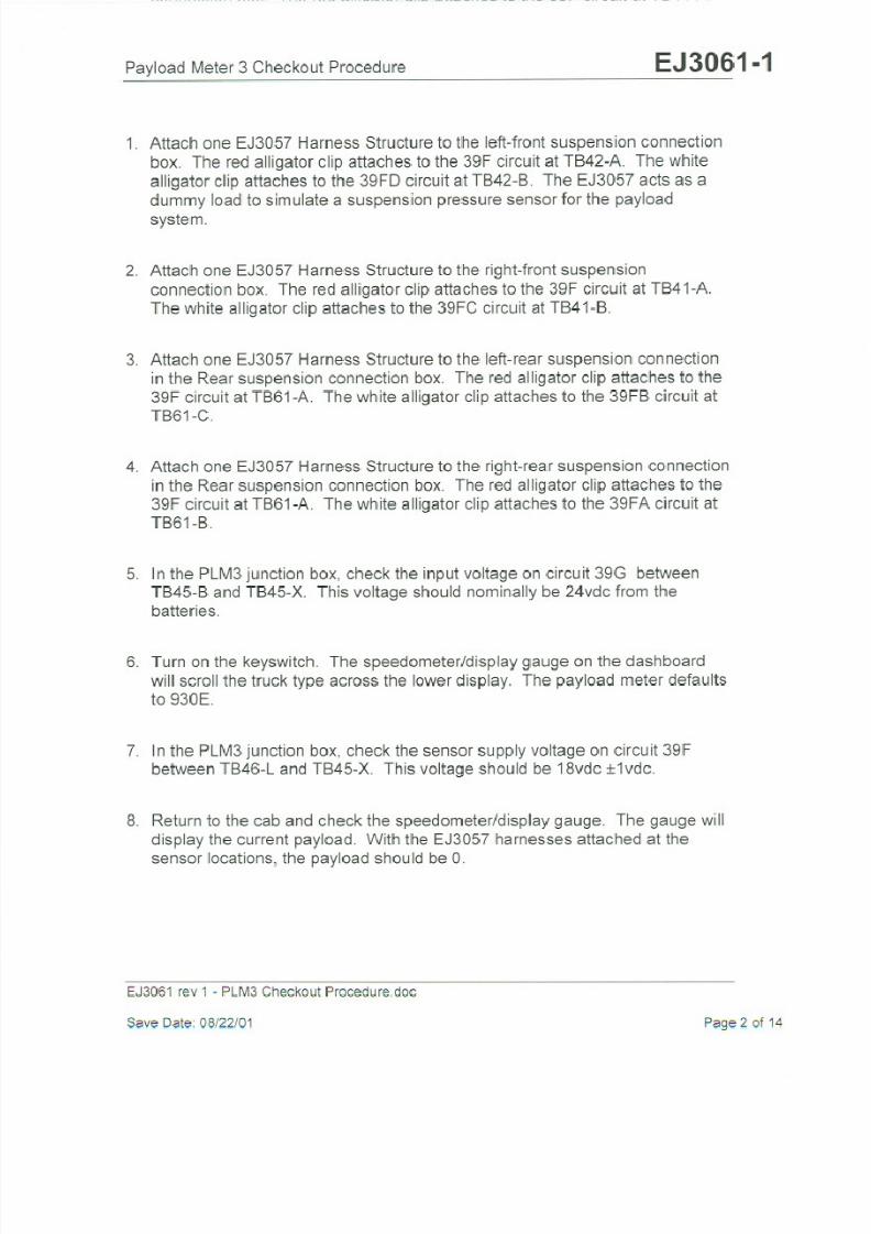
8/17/2019 Ce Aw 004101
http://slidepdf.com/reader/full/ce-aw-004101 178/265

8/17/2019 Ce Aw 004101
http://slidepdf.com/reader/full/ce-aw-004101 179/265

8/17/2019 Ce Aw 004101
http://slidepdf.com/reader/full/ce-aw-004101 180/265

8/17/2019 Ce Aw 004101
http://slidepdf.com/reader/full/ce-aw-004101 181/265

8/17/2019 Ce Aw 004101
http://slidepdf.com/reader/full/ce-aw-004101 182/265
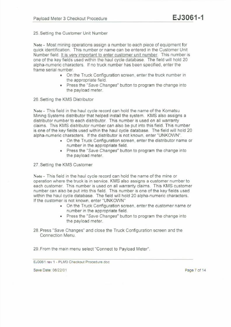
8/17/2019 Ce Aw 004101
http://slidepdf.com/reader/full/ce-aw-004101 183/265

8/17/2019 Ce Aw 004101
http://slidepdf.com/reader/full/ce-aw-004101 184/265

8/17/2019 Ce Aw 004101
http://slidepdf.com/reader/full/ce-aw-004101 185/265
8/17/2019 Ce Aw 004101
http://slidepdf.com/reader/full/ce-aw-004101 186/265
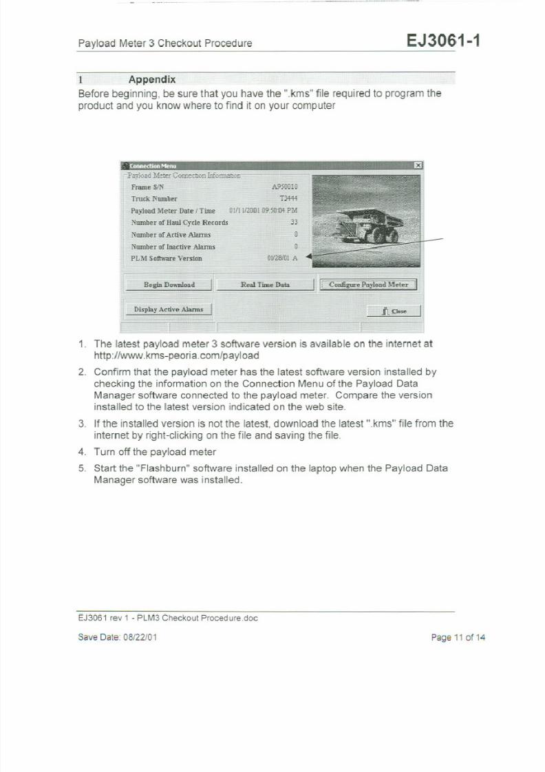
8/17/2019 Ce Aw 004101
http://slidepdf.com/reader/full/ce-aw-004101 187/265

8/17/2019 Ce Aw 004101
http://slidepdf.com/reader/full/ce-aw-004101 188/265
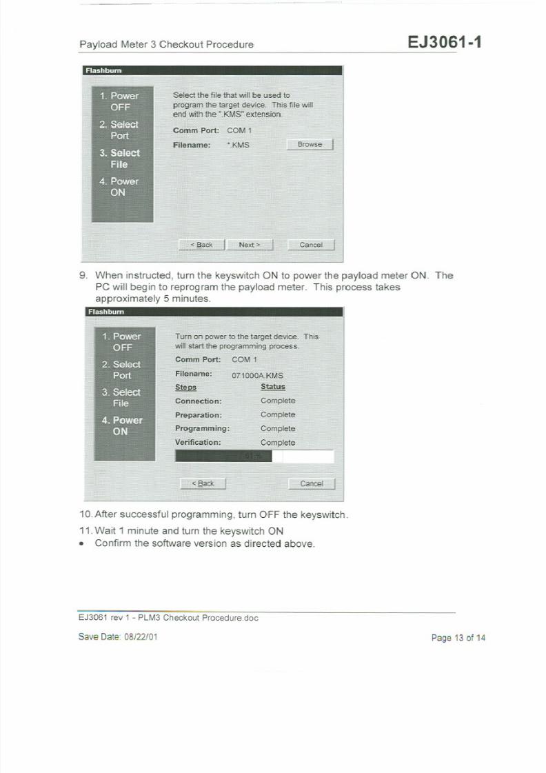
8/17/2019 Ce Aw 004101
http://slidepdf.com/reader/full/ce-aw-004101 189/265

8/17/2019 Ce Aw 004101
http://slidepdf.com/reader/full/ce-aw-004101 190/265

8/17/2019 Ce Aw 004101
http://slidepdf.com/reader/full/ce-aw-004101 191/265

8/17/2019 Ce Aw 004101
http://slidepdf.com/reader/full/ce-aw-004101 192/265

8/17/2019 Ce Aw 004101
http://slidepdf.com/reader/full/ce-aw-004101 193/265

8/17/2019 Ce Aw 004101
http://slidepdf.com/reader/full/ce-aw-004101 194/265

8/17/2019 Ce Aw 004101
http://slidepdf.com/reader/full/ce-aw-004101 195/265
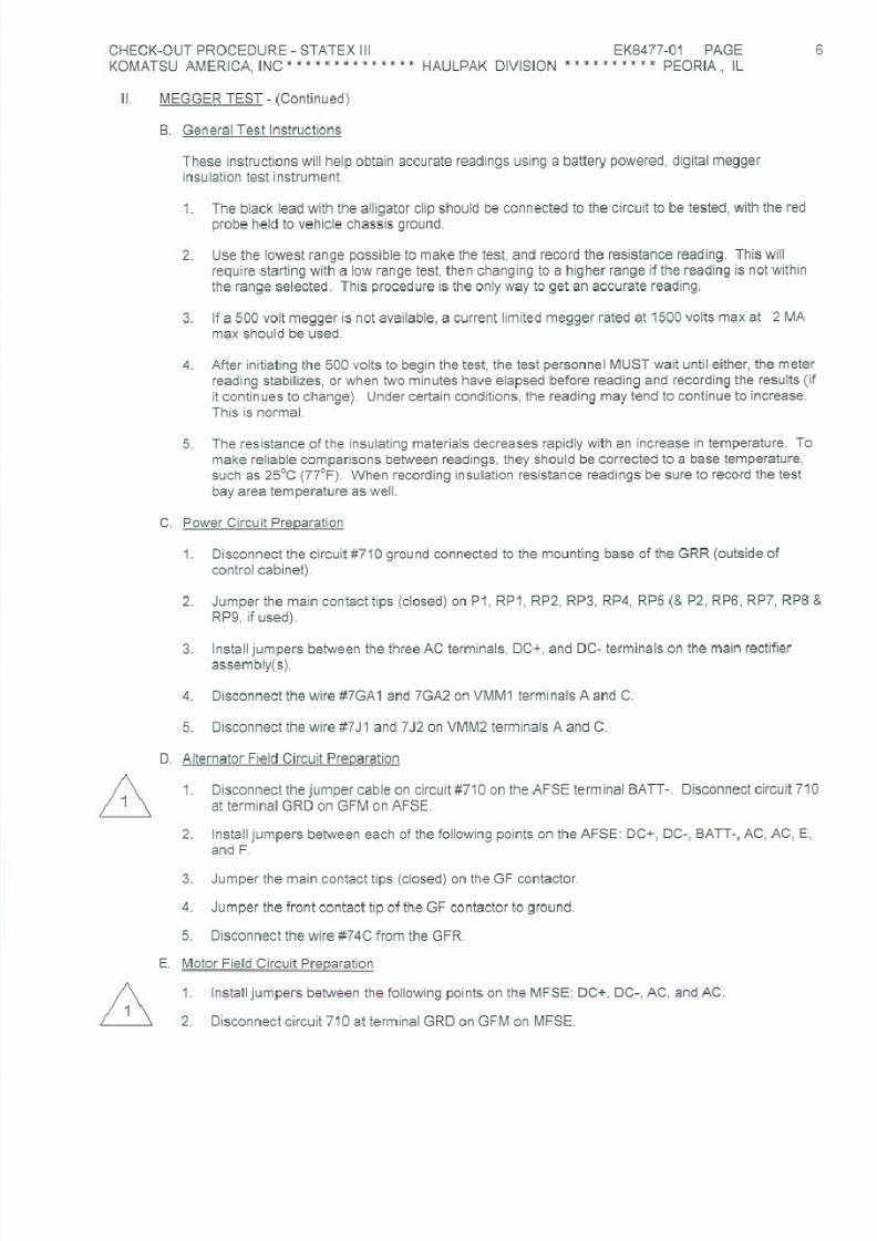
8/17/2019 Ce Aw 004101
http://slidepdf.com/reader/full/ce-aw-004101 196/265

8/17/2019 Ce Aw 004101
http://slidepdf.com/reader/full/ce-aw-004101 197/265

8/17/2019 Ce Aw 004101
http://slidepdf.com/reader/full/ce-aw-004101 198/265

8/17/2019 Ce Aw 004101
http://slidepdf.com/reader/full/ce-aw-004101 199/265

8/17/2019 Ce Aw 004101
http://slidepdf.com/reader/full/ce-aw-004101 200/265

8/17/2019 Ce Aw 004101
http://slidepdf.com/reader/full/ce-aw-004101 201/265
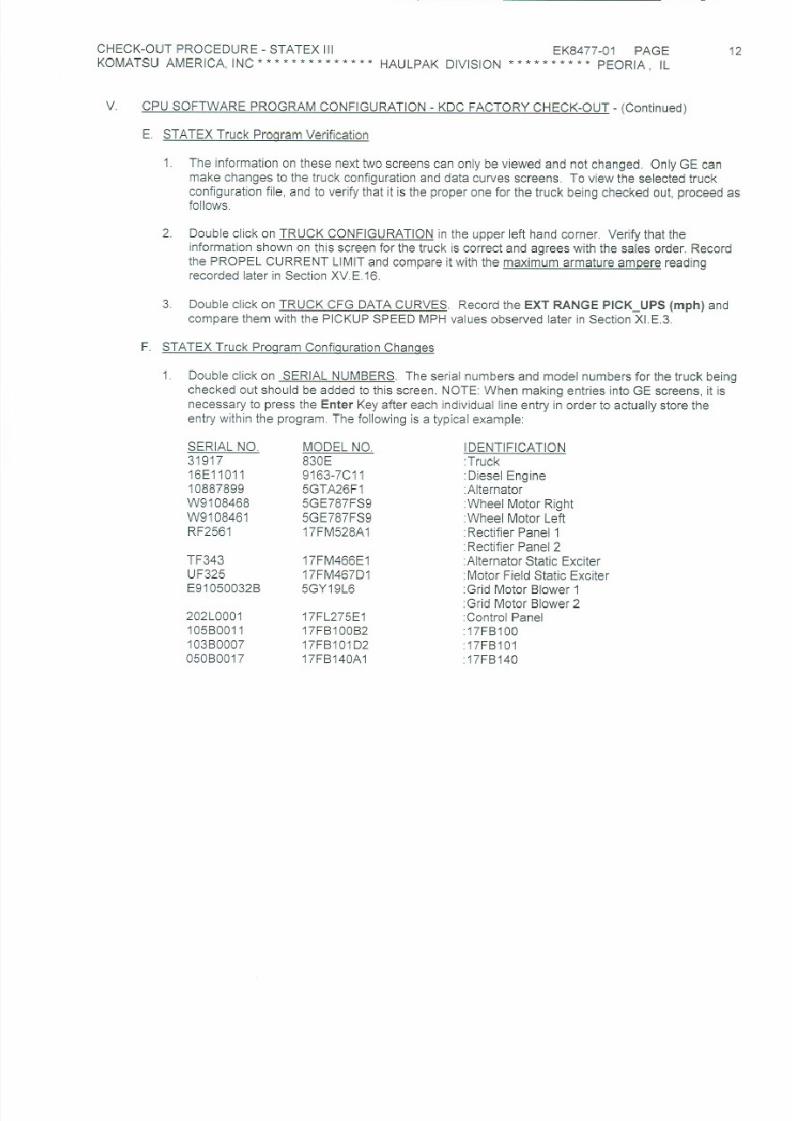
8/17/2019 Ce Aw 004101
http://slidepdf.com/reader/full/ce-aw-004101 202/265
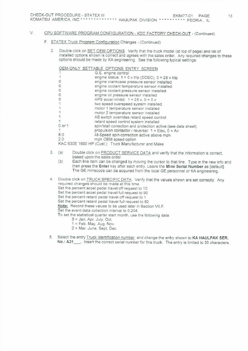
8/17/2019 Ce Aw 004101
http://slidepdf.com/reader/full/ce-aw-004101 203/265

8/17/2019 Ce Aw 004101
http://slidepdf.com/reader/full/ce-aw-004101 204/265

8/17/2019 Ce Aw 004101
http://slidepdf.com/reader/full/ce-aw-004101 205/265

8/17/2019 Ce Aw 004101
http://slidepdf.com/reader/full/ce-aw-004101 206/265

8/17/2019 Ce Aw 004101
http://slidepdf.com/reader/full/ce-aw-004101 207/265

8/17/2019 Ce Aw 004101
http://slidepdf.com/reader/full/ce-aw-004101 208/265

8/17/2019 Ce Aw 004101
http://slidepdf.com/reader/full/ce-aw-004101 209/265

8/17/2019 Ce Aw 004101
http://slidepdf.com/reader/full/ce-aw-004101 210/265

8/17/2019 Ce Aw 004101
http://slidepdf.com/reader/full/ce-aw-004101 211/265

8/17/2019 Ce Aw 004101
http://slidepdf.com/reader/full/ce-aw-004101 212/265

8/17/2019 Ce Aw 004101
http://slidepdf.com/reader/full/ce-aw-004101 213/265

8/17/2019 Ce Aw 004101
http://slidepdf.com/reader/full/ce-aw-004101 214/265
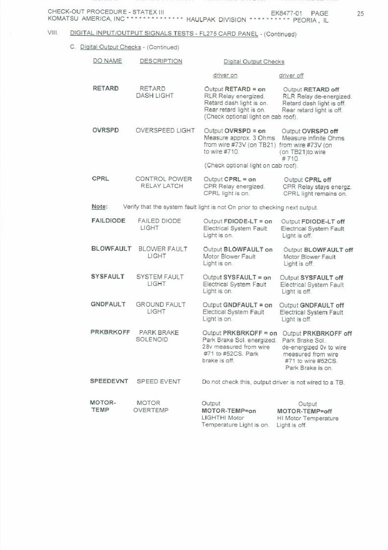
8/17/2019 Ce Aw 004101
http://slidepdf.com/reader/full/ce-aw-004101 215/265

8/17/2019 Ce Aw 004101
http://slidepdf.com/reader/full/ce-aw-004101 216/265

8/17/2019 Ce Aw 004101
http://slidepdf.com/reader/full/ce-aw-004101 217/265

8/17/2019 Ce Aw 004101
http://slidepdf.com/reader/full/ce-aw-004101 218/265

8/17/2019 Ce Aw 004101
http://slidepdf.com/reader/full/ce-aw-004101 219/265

8/17/2019 Ce Aw 004101
http://slidepdf.com/reader/full/ce-aw-004101 220/265

8/17/2019 Ce Aw 004101
http://slidepdf.com/reader/full/ce-aw-004101 221/265

8/17/2019 Ce Aw 004101
http://slidepdf.com/reader/full/ce-aw-004101 222/265

8/17/2019 Ce Aw 004101
http://slidepdf.com/reader/full/ce-aw-004101 223/265

8/17/2019 Ce Aw 004101
http://slidepdf.com/reader/full/ce-aw-004101 224/265

8/17/2019 Ce Aw 004101
http://slidepdf.com/reader/full/ce-aw-004101 225/265
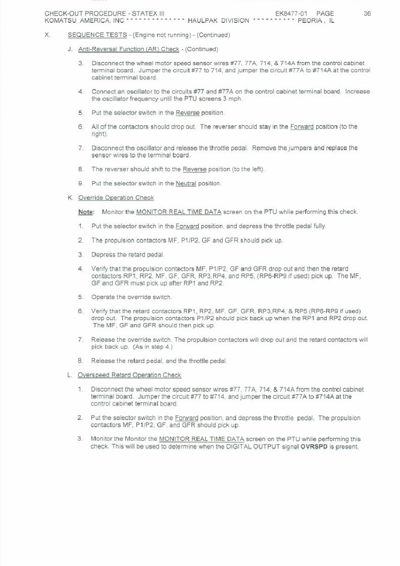
8/17/2019 Ce Aw 004101
http://slidepdf.com/reader/full/ce-aw-004101 226/265
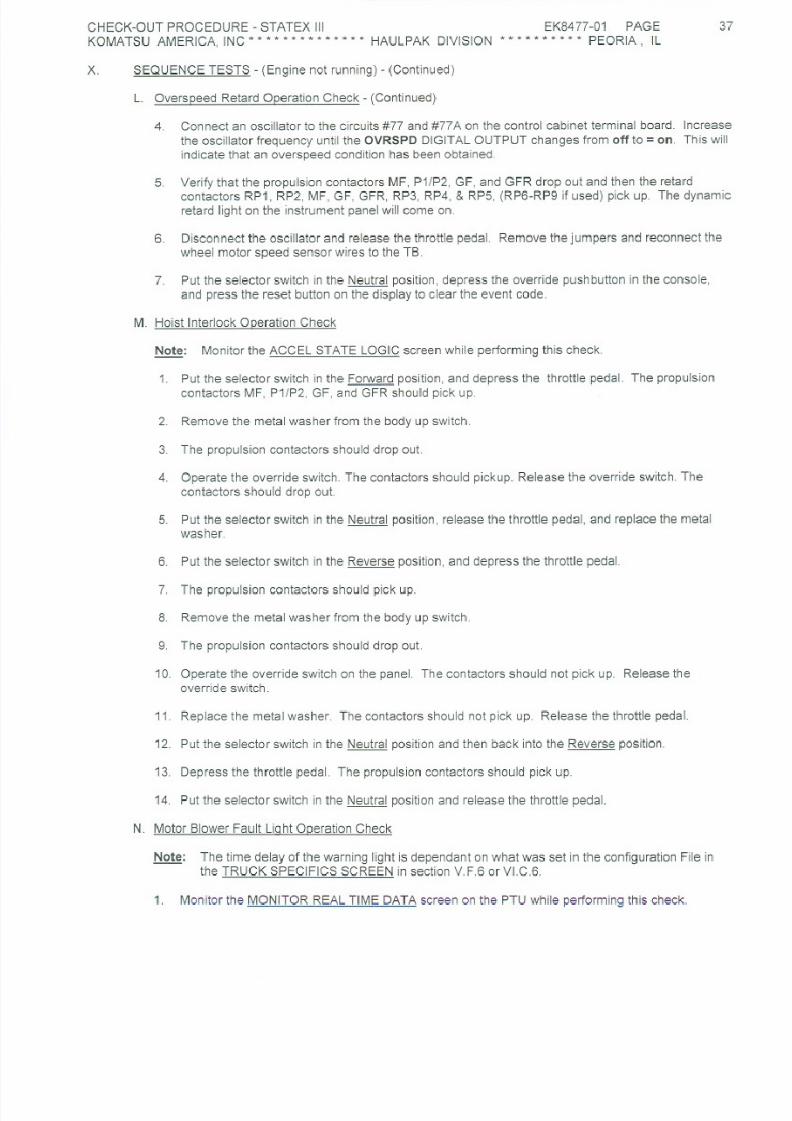
8/17/2019 Ce Aw 004101
http://slidepdf.com/reader/full/ce-aw-004101 227/265

8/17/2019 Ce Aw 004101
http://slidepdf.com/reader/full/ce-aw-004101 228/265

8/17/2019 Ce Aw 004101
http://slidepdf.com/reader/full/ce-aw-004101 229/265

8/17/2019 Ce Aw 004101
http://slidepdf.com/reader/full/ce-aw-004101 230/265

8/17/2019 Ce Aw 004101
http://slidepdf.com/reader/full/ce-aw-004101 231/265

8/17/2019 Ce Aw 004101
http://slidepdf.com/reader/full/ce-aw-004101 232/265

8/17/2019 Ce Aw 004101
http://slidepdf.com/reader/full/ce-aw-004101 233/265

8/17/2019 Ce Aw 004101
http://slidepdf.com/reader/full/ce-aw-004101 234/265

8/17/2019 Ce Aw 004101
http://slidepdf.com/reader/full/ce-aw-004101 235/265

8/17/2019 Ce Aw 004101
http://slidepdf.com/reader/full/ce-aw-004101 236/265

8/17/2019 Ce Aw 004101
http://slidepdf.com/reader/full/ce-aw-004101 237/265

8/17/2019 Ce Aw 004101
http://slidepdf.com/reader/full/ce-aw-004101 238/265

8/17/2019 Ce Aw 004101
http://slidepdf.com/reader/full/ce-aw-004101 239/265
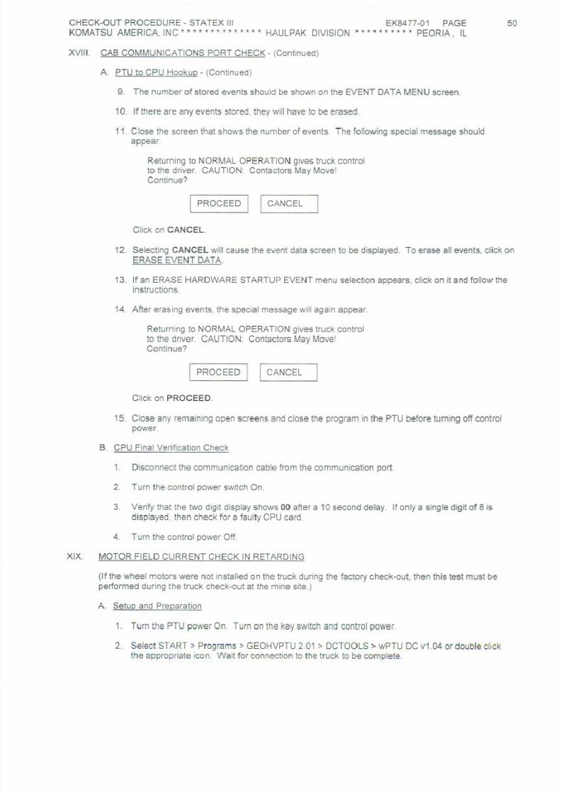
8/17/2019 Ce Aw 004101
http://slidepdf.com/reader/full/ce-aw-004101 240/265

8/17/2019 Ce Aw 004101
http://slidepdf.com/reader/full/ce-aw-004101 241/265

8/17/2019 Ce Aw 004101
http://slidepdf.com/reader/full/ce-aw-004101 242/265

8/17/2019 Ce Aw 004101
http://slidepdf.com/reader/full/ce-aw-004101 243/265

8/17/2019 Ce Aw 004101
http://slidepdf.com/reader/full/ce-aw-004101 244/265

8/17/2019 Ce Aw 004101
http://slidepdf.com/reader/full/ce-aw-004101 245/265

8/17/2019 Ce Aw 004101
http://slidepdf.com/reader/full/ce-aw-004101 246/265
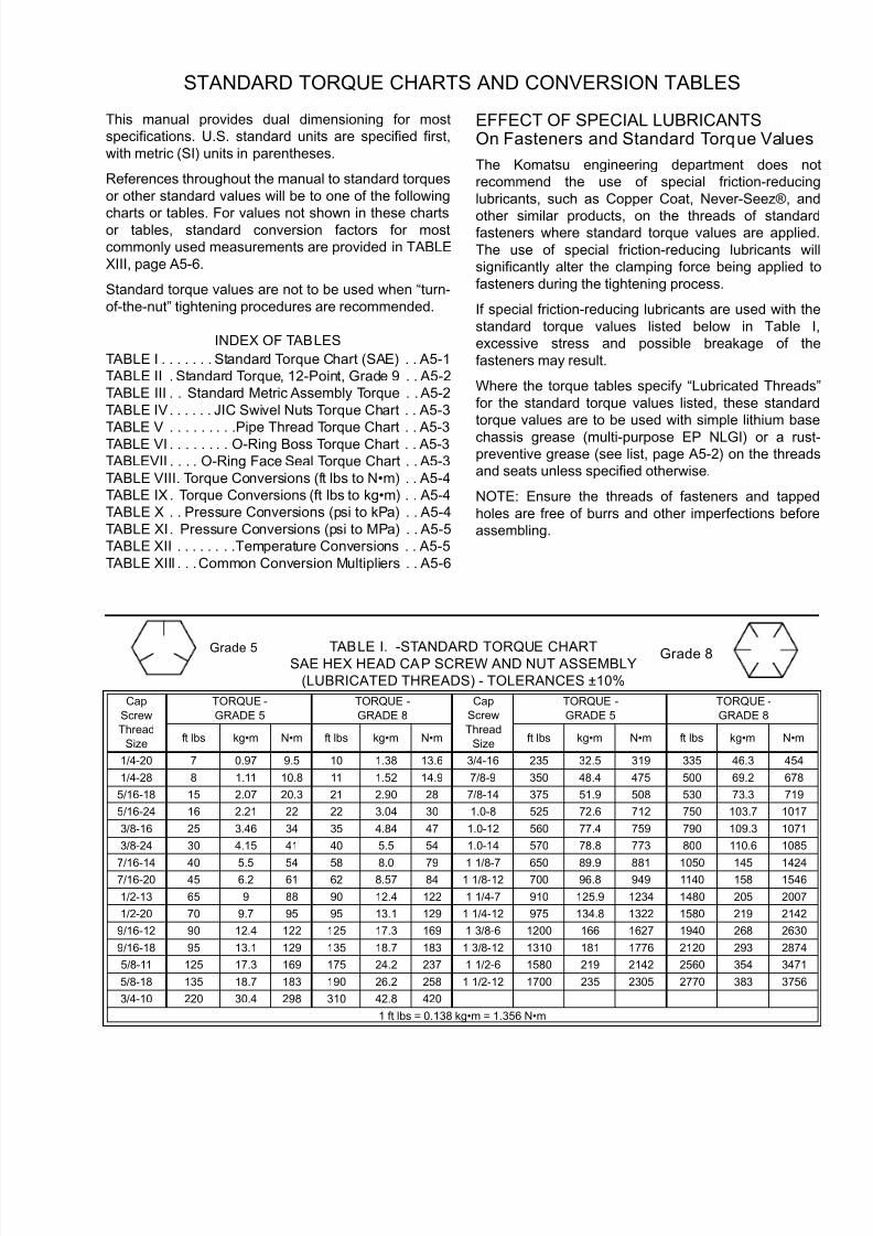
8/17/2019 Ce Aw 004101
http://slidepdf.com/reader/full/ce-aw-004101 247/265
STANDARD TORQUE CHARTS AND CONVERSION TABLES
This manual provides dual dimensioning for most
specifications. U.S. standard units are specified first,
with metric (SI) units in parentheses.
References throughout the manual to standard torques
or other standard values will be to one of the following
charts or tables. For values not shown in these chartsor tables, standard conversion factors for most
commonly used measurements are provided in TABLE
XIII, page A5-6.
Standard torque values are not to be used when “turn-
of-the-nut” tightening procedures are recommended.
INDEX OF TABLES
TABLE I . . . . . . . Standard Torque Chart (SAE) . . A5-1
TABLE II . Standard Torque, 12-Point, Grade 9 . . A5-2
TABLE III . . Standard Metric Assembly Torque . . A5-2
TABLE IV . . . . . . JIC Swivel Nuts Torque Chart . . A5-3
TABLE V . . . . . . . . .Pipe Thread Torque Chart . . A5-3TABLE VI . . . . . . . . O-Ring Boss Torque Chart . . A5-3
TABLEVII . . . . O-Ring Face Seal Torque Chart . . A5-3
TABLE VIII. Torque Conversions (ft lbs to N•m) . . A5-4
TABLE IX . Torque Conversions (ft lbs to kg•m) . . A5-4
TABLE X . . Pressure Conversions (psi to kPa) . . A5-4
TABLE XI. Pressure Conversions (psi to MPa) . . A5-5
TABLE XII . . . . . . . .Temperature Conversions . . A5-5
TABLE XIII . . .Common Conversion Multipliers . . A5-6
EFFECT OF SPECIAL LUBRICANTSOn Fasteners and Standard Torque Values
The Komatsu engineering department does no
recommend the use of special friction-reducing
lubricants, such as Copper Coat, Never-Seez®, and
other similar products, on the threads of standardfasteners where standard torque values are applied
The use of special friction-reducing lubricants wil
significantly alter the clamping force being applied to
fasteners during the tightening process.
If special friction-reducing lubricants are used with the
standard torque values listed below in Table I
excessive stress and possible breakage of the
fasteners may result.
Where the torque tables specify “Lubricated Threads
for the standard torque values listed, these standard
torque values are to be used with simple lithium base
chassis grease (multi-purpose EP NLGI) or a rustpreventive grease (see list, page A5-2) on the threads
and seats unless specified otherwise.
NOTE: Ensure the threads of fasteners and tapped
holes are free of burrs and other imperfections before
assembling.
TABLE I. -STANDARD TORQUE CHARTSAE HEX HEAD CAP SCREW AND NUT ASSEMBLY
(LUBRICATED THREADS) - TOLERANCES ±10%
Cap
Screw
Thread
Size
TORQUE -
GRADE 5
TORQUE -
GRADE 8
Cap
Screw
Thread
Size
TORQUE -
GRADE 5
TORQUE -
GRADE 8
ft lbs kg•m N•m ft lbs kg•m N•m ft lbs kg•m N•m ft lbs kg•m N•m
1/4-20 7 0.97 9.5 10 1.38 13.6 3/4-16 235 32.5 319 335 46.3 454
1/4-28 8 1.11 10.8 11 1.52 14.9 7/8-9 350 48.4 475 500 69.2 678
5/16-18 15 2.07 20.3 21 2.90 28 7/8-14 375 51.9 508 530 73.3 719
5/16-24 16 2.21 22 22 3.04 30 1.0-8 525 72.6 712 750 103.7 1017
3/8-16 25 3.46 34 35 4.84 47 1.0-12 560 77.4 759 790 109.3 1071
3/8-24 30 4.15 41 40 5.5 54 1.0-14 570 78.8 773 800 110.6 1085
7/16-14 40 5.5 54 58 8.0 79 1 1/8-7 650 89.9 881 1050 145 14247/16-20 45 6.2 61 62 8.57 84 1 1/8-12 700 96.8 949 1140 158 1546
1/2-13 65 9 88 90 12.4 122 1 1/4-7 910 125.9 1234 1480 205 2007
1/2-20 70 9.7 95 95 13.1 129 1 1/4-12 975 134.8 1322 1580 219 2142
9/16-12 90 12.4 122 125 17.3 169 1 3/8-6 1200 166 1627 1940 268 2630
9/16-18 95 13.1 129 135 18.7 183 1 3/8-12 1310 181 1776 2120 293 2874
5/8-11 125 17.3 169 175 24.2 237 1 1/2-6 1580 219 2142 2560 354 3471
5/8-18 135 18.7 183 190 26.2 258 1 1/2-12 1700 235 2305 2770 383 3756
3/4-10 220 30.4 298 310 42.8 420
1 ft lbs = 0.138 kg•m = 1.356 N•m
Grade 5 Grade 8

8/17/2019 Ce Aw 004101
http://slidepdf.com/reader/full/ce-aw-004101 248/265
STANDARD ASSEMBLY TORQUESFor 12-Point, Grade 9 Cap Screws (SAE)
The following specifications apply to required assembly
torques for all 12-point, grade 9 (170,000 psi minimum
tensile) cap screws.
• Cap screw threads and seats shall be lubricatedwhen assembled.
NOTE: Unless the instructions specifically recommend
otherwise, these standard torque values are to be used
with simple lithium base chassis grease (multi-purpose
EP NLGI) or a rust preventive grease (see list, this
page) on the threads.
• Torques are calculated to give a clamping force of approximately 75% of proof load.
• The maximum torque tolerance shall be ±10% of the torque value shown.
STANDARD ASSEMBLY TORQUESFor Class 10.9 Cap screws & Class 10 Nuts
The following specifications apply to required assembly
torques for all metric Class 10.9 finished hexagon head
cap screws and Class 10 nuts.
• Cap screw threads and seats shall not belubricated when assembled. These specifications
are based on all cap screws, nuts, and hardenedwashers being phosphate and oil coated.
NOTE: If zinc-plated hardware is used, each piece
must be lubricated with simple lithium base chassis
grease (multi-purpose EP NLGI) or a rust preventive
grease (see list, this page) to achieve the same
clamping forces provided below.
• Torques are calculated to give a clamping force of approximately 75% of proof load.
• The maximum torque tolerance shall be within±10% of the torque value shown.
Suggested* Sources for Rust Preventive Grease:
• AMERICAN ANTI-RUST GREASE #3-X fromStandard Oil Company (also American Oil Co.)
• GULF NORUST #3 from Gulf Oil Company.
• MOBILARMA 355, Product No. 66705 from MobilOil Corporation.
• RUST BAN 326 from Humble Oil Company.
• RUSTOLENE B GREASE from Sinclair Oil Co.
• RUST PREVENTIVE GREASE - CODE 312 fromthe Southwest Grease and Oil Company.
NOTE: This list represents the current engineering
approved sources for use in Komatsu manufacture. It is
not exclusive. Other products may meet the same
specifications of this list.
TABLE II. STANDARD ASSEMBLY TORQUE
for 12-Point, Grade 9 Cap screws
CAP SCREW
SIZE*
TORQUE
ft lbs
TORQUE
N•m
TORQUE
kg•m
0.250 - 20 12 16 1.7
0.312 - 18 24 33 3.3
0.375 - 16 42 57 5.8
0.438 -14 70 95 9.7
0.500 -13 105 142 14.5
0.562 - 12 150 203 20.7
0.625 - 11 205 278 28.3
0.750 - 10 360 488 49.7
0.875 - 9 575 780 79.4
1.000 - 8 860 1166 119
1.000 - 12 915 1240 126
1.125 - 7 1230 1670 170
1.125 - 12 1330 1800 184
1.250 - 7 1715 2325 237
1.250 - 12 1840 2495 254
1.375 - 6 2270 3080 313
1.375 - 12 2475 3355 342
1.500 - 6 2980 4040 411
1.500 - 12 3225 4375 445
* Shank Diameter (in.) - Threads per inch
This table represents standard values only. Do not use these
values to replace torque values which are specified in assembly
instructions.
TABLE III. STANDARD ASSEMBLY TORQUEfor Metric Class 10.9 Cap screws & Class 10 Nuts
CAP SCREW
SIZE*
TORQUE
N•m
TORQUE
ft lbs
TORQUE
kg•m
M6 x1 12 9 1.22
M8 x 1.25 30 22 3.06
M10 x 1.5 55 40 5.61
M12 x 1.75 95 70 9.69
M14 x 2 155 114 15.81
M16 x 2 240 177 24.48
M20 x 2.25 465 343 47.43
M24 x 3 800 590 81.6
M30 x 3.5 1600 1180 163.2
M36 x 4 2750 2028 280.5
* Shank Diameter (mm) - Threads per millimeter
This table represents standard values only. Do not use these
values to replace torque values which are specified in assembly
instructions.

8/17/2019 Ce Aw 004101
http://slidepdf.com/reader/full/ce-aw-004101 249/265
TABLE IV.TORQUE CHART FOR JIC 37° SWIVEL NUTS
WITH OR WITHOUT O-RING SEALS
SIZE
CODE
TUBE SIZE
(O.D.)
THREADS
UNF-2B
TORQUE
ft lbs
– 2 0.125 0.312 – 24 4 ±1
– 3 0.188 0.375 – 24 8 ±3
– 4 0.250 0.438 – 20 12 ±3
– 5 0.312 0.500 – 20 15 ±3
– 6 0.375 0.562 – 18 18 ±5
– 8 0.500 0.750 – 16 30 ±5
– 10 0.625 0.875 – 14 40 ±5
– 12 0.750 1.062 – 12 55 ±5
– 14 0.875 1.188 – 12 65 ±5
– 16 1.000 1.312 – 12 80 ±5
– 20 1.250 1.625 – 12 100 ±10
– 24 1.500 1.875 – 12 120 ±10
– 32 2.000 2.500 – 12 230 ±20
TABLE V.
TORQUE CHART FOR
PIPE THREAD FITTINGS
SIZE
CODE
PIPE
THREAD
SIZE
WITH
SEALANT
ft lbs
WITHOUT
SEALANT
ft lbs
– 2 0.125 – 27 15 ±3 20 ±5
– 4 0.250 – 18 20 ±5 25 ±5
– 6 0.375 – 18 25 ±5 35 ±5 – 8 0.500 – 14 35 ±5 45 ±5
– 12 0.750 – 14 45 ±5 55 ±5
– 16 1.000 – 11.50 55 ±5 65 ±5
– 20 1.250 – 11.50 70 ±5 80 ±5
– 24 1.500 – 11.50 80 ±5 95 ±10
– 32 2.000 – 11.50 95 ±10 120 ±10
TABLE VI.TORQUE CHART FOR
O-RING BOSS FITTINGS
SIZE
CODE
TUBE SIZE
(O.D.)
THREADS
UNF-2B
TORQUE
ft lbs
– 2 0.125 0.312 – 24 4 ±2
– 3 0.188 0.375 – 24 5 ±2
– 4 0.250 0.438 – 20 8 ±3
– 5 0.312 0.500 – 20 10 ±3
– 6 0.375 0.562 – 18 13 ±3
– 8 0.500 0.750 – 16 24 ±5
– 10 0.625 0.875 – 14 32 ±5
– 12 0.750 1.062 – 12 48 ±5
– 14 0.875 1.188 – 12 54 ±5
– 16 1.000 1.312 – 12 72 ±5
– 20 1.250 1.625 – 12 80 ±5
– 24 1.500 1.875 – 12 80 ±5
– 32 2.000 2.500 – 12 96 ±10
TABLE VII.
TORQUE CHART FOR
O-RING FACE SEAL FITTINGS
SIZE
CODE
TUBE SIZE
(O.D.)
THREADS
UNF-2B
TORQUE ft
lbs
– 4 0.250 0.438 – 20 11 ±1
– 6 0.375 0.562 – 18 18 ±2
– 8 0.500 0.750 – 16 35 ±4
– 10 0.625 0.875 – 14 51 ±5
– 12 0.750 1.062 – 12 71 ±7
– 16 1.000 1.312 – 12 98 ±6
– 20 1.250 1.625 – 12 132 ±7
– 24 1.500 1.875 – 12 165 ±15

8/17/2019 Ce Aw 004101
http://slidepdf.com/reader/full/ce-aw-004101 250/265
TABLE VIII. TORQUE CONVERSIONS
Foot Pounds (ft lbs) to Newton-meters (N•m)
ft lbs 0 1 2 3 4 5 6 7 8 9
0 (N.m) 1.36 2.71 4.07 5.42 6.78 8.14 9.49 10.85 12.20
10 13.56 14.91 16.27 17.63 18.98 20.34 21.69 23.05 24.40 25.76
20 27.12 28.47 29.83 31.18 32.54 33.90 35.25 36.61 37.96 39.32
30 40.67 42.03 43.39 44.74 46.10 47.45 48.81 50.17 51.52 52.87
40 54.23 55.59 56.94 58.30 59.66 60.01 62.37 63.72 65.08 66.44
50 67.79 69.15 70.50 71.86 73.21 74.57 75.93 77.28 78.64 80.00
60 81.35 82.70 84.06 85.42 86.77 88.13 89.48 90.84 92.20 93.55
70 94.91 96.26 97.62 98.97 100.33 101.69 103.04 104.40 105.75 107.11
80 108.47 109.82 111.18 112.53 113.89 115.24 116.60 117.96 119.31 120.67
90 122.03 123.38 124.74 126.09 127.45 128.80 130.16 131.51 132.87 134.23
See NOTE on page A5-5 regarding Table usage
TABLE IX. TORQUE CONVERSIONS
Foot Pounds (ft lbs) to ki logram-meters (kg•m)
ft lbs 0 1 2 3 4 5 6 7 8 9
0 (kg.m) 0.138 0.277 0.415 0.553 0.692 0.830 0.968 1.106 1.245
10 1.38 1.52 1.66 1.80 1.94 2.07 2.21 2.35 2.49 2.63
20 2.77 2.90 3.04 3.18 3.32 3.46 3.60 3.73 3.87 4.01
30 4.15 4.29 4.43 4.56 4.70 4.84 4.98 5.12 5.26 5.39
40 5.53 5.67 5.81 5.95 6.09 6.22 6.36 6.50 6.64 6.78
50 6.92 7.05 7.19 7.33 7.47 7.61 7.74 7.88 8.02 8.16
60 8.30 8.44 8.57 8.71 8.85 8.99 9.13 9.27 9.40 9.54
70 9.68 9.82 9.96 10.10 10.23 10.37 10.51 10.65 10.79 10.93
80 11.06 11.20 11.34 11.48 11.62 11.76 11.89 12.03 12.17 12.30
90 12.45 12.59 12.72 12.86 13.00 13.14 13.28 13.42 13.55 13.69
See NOTE on page A5-5 regarding Table usage
TABLE X. PRESSURE CONVERSIONS
Pounds/square inch (psi) To Kil opascals (kPa)
Formula: psi x 6.895 = kPa
psi 0 1 2 3 4 5 6 7 8 9
0 (kPa) 6.895 13.79 20.68 27.58 34.47 41.37 48.26 55.16 62.05
10 68.95 75.84 82.74 89.63 96.53 103.42 110.32 117.21 124.1 131.0
20 137.9 144.8 151.7 158.6 165.5 172.4 179.3 186.2 193.1 200.0
30 206.8 213.7 220.6 227.5 234.4 241.3 248.2 255.1 262.0 268.9
40 275.8 282.7 289.6 296.5 303.4 310.3 317.2 324.1 331.0 337.9
50 344.7 351.6 358.5 365.4 372.3 379.2 386.1 393.0 399.9 406.8
60 413.7 420.6 427.5 434.4 441.3 448.2 455.1 462.0 468.9 475.8
70 482.6 489.5 496.4 503.3 510.2 517.1 524.0 530.9 537.8 544.7
80 551.6 558.5 565.4 572.3 579.2 586.1 593.0 599.9 606.8 613.7
90 620.5 627.4 634.3 641.2 648.1 655.0 661.9 668.8 675.7 682.6
See NOTE on page A5-5 regarding Table usage

8/17/2019 Ce Aw 004101
http://slidepdf.com/reader/full/ce-aw-004101 251/265
TABLE XI. PRESSURE CONVERSIONS
Pounds/square inch (psi) To Megapascals (MPa)
Formula: ps i x 0.0069 = MPa
psi 0 10 20 30 40 50 60 70 80 90
0 (MPa) 0.069 0.14 0.21 0.28 0.34 0.41 0.48 0.55 0.62
100 0.69 0.76 0.83 0.90 0.97 1.03 1.10 1.17 1.24 1.31
200 1.38 1.45 1.52 1.59 1.65 1.72 1.79 1.86 1.93 2.00
300 2.07 2.14 2.21 2.28 2.34 2.41 2.48 2.55 2.62 2.69
400 2.76 2.83 2.90 2.96 3.03 3.10 3.17 3.24 3.31 3.38
500 3.45 3.52 3.59 3.65 3.72 3.79 3.86 3.93 4.00 4.07
600 4.14 4.21 4.27 4.34 4.41 4.48 4.55 4.62 4.69 4.76
700 4.83 4.90 4.96 5.03 5.10 5.17 5.24 5.31 5.38 5.45
800 5.52 5.58 5.65 5.72 5.79 5.86 5.93 6.00 6.07 6.14
900 6.21 6.27 6.34 6.41 6.48 6.55 6.62 6.69 6.76 6.83
See NOTE below regarding Table usage
TABLE XII. TEMPERATURE CONVERSIONS
Formula: F° - 32 / 1.8 = C° or C° x 1.8 + 32 = F°
CELSIUSC°
FAHRENHEITF°
CELSIUSC°
FAHRENHEITF°
CELSIUSC°
FAHRENHEITF°
121 250 482 63 145 293 4 40 104
118 245 473 60 140 284 2 35 95
116 240 464 57 135 275 – 1 30 86113 235 455 54 130 266 – 4 25 77
110 230 446 52 125 257 – 7 20 68
107 225 437 49 120 248 – 9 15 59
104 220 428 46 115 239 – 12 10 50
102 215 419 43 110 230 – 15 5 41
99 210 410 41 105 221 – 18 0 32
96 205 401 38 100 212 – 21 – 5 23
93 200 392 35 95 293 – 23 – 10 14
91 195 383 32 90 194 – 26 – 15 5
88 190 374 29 85 185 – 29 – 20 – 4
85 185 365 27 80 176 – 32 – 25 – 13
82 180 356 24 75 167 – 34 – 30 – 22
79 175 347 21 70 158 – 37 – 35 – 31
77 170 338 18 65 149 – 40 – 40 – 4074 165 329 15 60 140 – 43 – 45 – 49
71 160 320 13 55 131 – 46 – 50 – 58
68 155 311 10 50 122 – 48 – 55 – 67
66 150 302 7 45 113 – 51 – 60 – 76
NOTE: The numbers in the unmarked columns refer to temperature in either degrees Celsius (C°) or Fahrenheit (F°). Select a number in
this unmarked column and read to the left to convert to degrees Celsius (C°) or read to the right to convert to degrees Fahrenheit (F°). If
starting with a known temperature (either C° or F°), find that temperature in the marked column and read the converted temperature in the
center, unmarked column.
NOTE: Tables such as Table VIII, IX, X, and XI may be used as in the following example:
Example: Convert 975 psi to kilopascals (kPa).
1. Select Table X.
2. Go to psi row 90, column 7; read 668.8
97 psi = 668.8 kPa.
3. Multiply by 10:970 psi = 6688 kPa.
4. Go to psi row 0, column 5; read 34.475
psi = 34.47 kPa. Add to step 3.
5. 970 + 5 psi = 6688 + 34 = 6722 kPa.

8/17/2019 Ce Aw 004101
http://slidepdf.com/reader/full/ce-aw-004101 252/265
TABLE XIII
COMMON CONVERSION MULTIPLIERS
COMMON CONVERSION MULTIPLIERS
ENGLISH TO METRIC
To Convert
From TO
Multiply
By
inch – in. millimeter (mm) 25.40
inch – in. centimeter (cm) 2.54
foot – ft meter (m) 0.3048
yard – yd meter (m) 0.914
mile – mi. kilometer (km) 1.61
sq. in. – in.2 sq. centimeters (cm2) 6.45
sq. ft. – ft2 sq. centimeters (cm2) 929
cu. in. – in.3 cu. centimeters (cm3) 16.39
cu. in. – in.3 liters (l) 0.016
cu. ft. – ft3 cu. meters (m3) 0.028
cu. ft. – ft3 liters (l) 28.3
ounce – oz kilogram (kg) 0.028
fluid ounce – fl oz milliliter (ml) 29.573
pound (mass) kilogram (kg) 0.454
pound (force) – lbs Newton (N) 4.448
in. lbs. (force) Newton meters (N•m) 0.113
ft lbs (force) Newton meters (N•m) 1.356
ft lbs (force) kilogram meters (kg•m) 0.138
psi (pressure) kilopascals (kPa) 6.895
psi (pressure) megapascals (MPa) 0.007
psi (pressure) kilograms/cm2 (kg/cm2) 0.0704
ton (short) kilogram (kg) 907.2
ton (short) metric ton 0.0907
quart – qt liters (l) 0.946
gallon – gal liters (l) 3.785
HP (horsepower) Watts 745.7
HP (horsepower) kilowatts (kw) 0.745
COMMON CONVERSION MULTIPLIERS
METRIC TO ENGLISH
To Convert From TO
Multiply
By
millimeter (mm) inch – in. 0.0394
centimeter (cm) inch – in. 0.3937
meter (m) foot – ft 3.2808
meter (m) yard – yd 1.0936
kilometer (km) mile – mi. 0.6210
sq. centimeters (cm2) sq. in. – in.2 0.1550
sq. centimeters (cm2) sq. ft. – ft2 0.001
cu. centimeters (cm3) cu in – in.3 0.061
liters (l) cu in – in.3 61.02
cu. meters (m3) cu ft – ft3 35.314
liters (l) cu ft – ft3 0.0353
grams (g) ounce – oz. 0.0353
milliliter (ml) fluid ounce – fl oz. 0.0338
kilogram (kg) pound (mass) 2.2046
Newton (N) pound (force) – lbs 0.2248
Newton-meters (N•m) kilogram meters (kg•m) 0.102
Newton-meters (N.m) ft lbs 0.7376
kilogram-meters (kg•m) ft lbs 7.2329
kilogram-meters (kg•m) Newton meters (N•m) 9.807
kilopascals (kPa) psi 0.1450
megapascals (MPa) psi 145.038
kilograms/cm2 (kg/cm2) psi 14.2231
kilograms/cm2 (kg/cm2) kilopascals (kPa) 98.068
kilogram (kg) ton 0.0011
metric ton ton 1.1023
liters (l) quart – qt 1.0567
liters (l) gallon – gal 0.2642
Watts Horsepower HP 0.00134
kilowatts (kw) Horsepower HP 1.3410

8/17/2019 Ce Aw 004101
http://slidepdf.com/reader/full/ce-aw-004101 253/265
CEAW003209 White - Komatsu, Manager of Technical Support Canary - Komatsu, Manager of Field Assembly Page 1 of 5
Pink - Komatsu, Regional Service Manager Gold - Komatsu Distributor, Service Manager
FIELD ASSEMBLY INSPECTION REPORT
After completion of assembling a machine, make inspections according to these check sheets for assuring machine performance and quality.
Inspector’s Comments:
Submitting of this report (and check sheets) to Komatsu is one of the cond itions of warranty validation.
Al l four copies are to be distr ibuted as shown below.
Send White Reports to Manager of Technical Support
Komatsu America Corp.
2300 N.E. Adams St, P.O. Box 240
Peoria, IL 61650-0240 U.S.A.
Send Canary Reports to Manager of Field Assembly
Komatsu America Corp.2300 N.E. Adams St, P.O. Box 240
Peoria, IL 61650-0240 U.S.A.
Send Pink Reports to your KAC Regional Service Manager
Send Gold Reports to the Service Manager at the KAC Distributor who sold the truck.
Mark each item with the appropriate symbol as shown below.
MACHINE MODEL(Circle One)
730E 830E
830E-AC 930E-4
MACHINE
SERIAL NUMBER
ENGINE MODEL ENGINE
SERIAL NUMBER
CUSTOMER UNIT
NUMBER
Service Meter Reading Date of Inspection Wheel Motor
Serial Numbers LH RH
Location of Machine at Inspection
Dump Body Manufacturer
Komatsu Other
Distributor’s Name Dump Body Style
Customer’s Name KAC Area Service Manager Signature Date
Customer’s Address
Inspector’s Name
KOMATSU USE ONLY:
Sheet receiving Date:
Title
By:
Signature
Remark:

8/17/2019 Ce Aw 004101
http://slidepdf.com/reader/full/ce-aw-004101 254/265
CEAW003209 White - Komatsu, Manager of Technical Support Canary - Komatsu, Manager of Field Assembly Page 2 of 5
Pink - Komatsu, Regional Service Manager Gold - Komatsu Distributor, Service Manager
NOTE: Refer to Section G, Tires and Rims, in the appropriate service manual for the complete wheel mount-
ing ti ghtening procedure.
No. Inspection Item Acceptance Procedures A c c e p t e d
M a i n t e n a n c e
Inspection Around Machine
1 Parts Visual inspection of unit for loose parts and debris
2 Hardware Visual inspection of unit for missing and/or loose mounting hardware
3 Hoses and Cables Visual inspection of hydraulic hoses and electric cables to ensure they are securely
clamped and clear from sharp edges and not rubbing each other
4 Ground Straps Verify all ground straps are secure (sub frame, anchor etc.)
5 Engine Oil Level Verify engine oil level is in operating range
6 Engine Fan Inspect fan-to-shroud clearance and belt alignment
7 Hydraulic Oil Level Oil level visible through the upper sight glass with body down
8 Hatch Door
(730E, 830E)
Verify adequate latch seal on the rear axle hatch door to prevent dust entry
9 Anchor Pin Visually inspect anchor hitch pin and anti-sway bar assembly for proper assembly and prop-
erly tightened hardware10 Wheel Motors Inspect oil specification and proper oil level
11 Fuel Tank Verify fuel tank mounting is secure and there are no fuel leaks
12 Radiator Inspect coolant fill level, cold temperature protection, and DCA additive
13 Decks and Ladders Inspect all ladders and handrails are secure and hardware is tight
Visual inspection of installation of grid blower, rectifier assembly and control box for correct
assembly of components and proper clamping, no loose contacts, no damaged or poorly
crimped cables
14 Battery Inspect all wiring and connections in battery box - no rubbing or chafing
Verify battery mounting hardware is secure
Verify electrolyte at proper level and caps are securely installed
Verify all battery terminals are secure
15 Frame Visually inspect installation of steering cylinders, tie rod, and accumulators per print
Visually inspect hoist valve, pumps, filters, hydraulic tank and hoist cylinder
installations (all hardware secure, no leaks)
Hardware Torque
1 Suspension Verify front suspension mounting cap screws have been properly tightened per appropriate
service manual procedure using the “turn-of-the-nut” method
2 Wheels 730E
(See Note below chart)
Verify torque on all wedge nuts at 746 N·m (550 ft l bs)
830E, 830E-AC
(See Note below chart)
Verify torque on all wedge nuts at 746 N·m (550 ft l bs)
930E-4
(See Note below chart)
Verify torque on front wheel nuts at 2326 ± 136 N·m (1715 ± 100 ft lbs)
Verify torque on rear inside wheel nuts at 2326 ± 136 N·m (1715 ± 100 ft lbs)
Verify torque on rear outside wheel nuts and adapter ring at 2326 ± 136 N·m (1715 ± 100 ft
lbs)
3 Rops Verify torque on left rops beam cap screws at 949 N·m (700 ft lbs)
Verify torque on right cross beam cap screws at 240 N·m (177 ft lbs)
4 Cab Verify torque on cab mounting cap screws at 949 N·m (700 ft lbs)
5 Wheel Motor Verify torque on wheel motor mounting cap screws at 2007 N·m (1480 ft lbs)

8/17/2019 Ce Aw 004101
http://slidepdf.com/reader/full/ce-aw-004101 255/265
CEAW003209 White - Komatsu, Manager of Technical Support Canary - Komatsu, Manager of Field Assembly Page 3 of 5
Pink - Komatsu, Regional Service Manager Gold - Komatsu Distributor, Service Manager
No. Inspection Item Acceptance Procedures A c c e p t e d
M a i n t e n a n c e
Cab Compartment1 Cab Doors Verify doors open and close smoothly, latch works properly, O&M manual in door
2 Cab Windows Verify windows can be opened and closed smoothly
3 Door Locks Verify left and right door locks work properly with key
4 Interior Visually inspect interior for completeness of assembly
Visually inspect for cracked glass, torn upholstery, dirt, stains, holes etc.
5 Cab Seats Inspect operators seat adjustments (slide lever, back rest operation,
seat inclination, seat height etc.)
Inspect seat belt for proper installation (and seat tethers)
6 Passenger Seat Verify back rest operates without interference
7 Steering Wheel Check tilt and telescoping functions
Check adjustable lever can be locked securely
8 Wiper Verify wiper works all speeds, & range does not extend beyond glass surface
Verify the windshield washer works properly and washer fluid bottle is full
9 Cigarette Lighter Check lighter operation, should pop up after 10 seconds and be hot
10 Horn Check for proper sound, no looseness in horn button
11 Back Up Horn Check for proper sound, and function
12 Shift Tower Check for proper function, no binding or looseness
13 Gauges Verify gauges are installed straight and operating correctly
14 Hydraulic Fittings Visually inspect all hydraulic fittings in front of cab, rear of cab, and hydraulic brake cabinet
15 Hoist Check operation of the hoist lever in all four positions
Lights
1 Headlights Verify all headlights working, high and low beams
Verify high beam indicators are functional
Verify lights at proper angle
2 Instrument Panel Check switch depresses and all lights function
2a Dimmer Switch Verify dimmer operates properly
2b Turn Signal Visually inspect front and rear turn signal operation on left and right sides
Directional indicators operate properly
Switch turns off after turn is completed
3 Hazard Flashers Verify flasher operates properly
Verify hazard indicator lights operating properly
4 Back Up Light Verify back up light operates properly when shifter is in R position
5 Manual Back Up Light Verify switch and light work properly
6 Fog Light (optional) Verify fog l ights and indicator lights operating properly
Brake Lights
1 Service Brake Verify service brake lights operating properly
2 Brake Lock Verify brake lock light operating properly
3 Emergency Brake Verify emergency brake light operating properly
4 Parking Brake Verified parking brake light operating properly
5 Dome Light Verify dome light is on when the switch is ON
6 Retarder Lights Verify retard light operating properly

8/17/2019 Ce Aw 004101
http://slidepdf.com/reader/full/ce-aw-004101 256/265
CEAW003209 White - Komatsu, Manager of Technical Support Canary - Komatsu, Manager of Field Assembly Page 4 of 5
Pink - Komatsu, Regional Service Manager Gold - Komatsu Distributor, Service Manager
NOTE: Refer to Section H, Oiling and Charging Procedure, in the appropr iate service manual for complete
suspension oiling and charging instructi ons.
No. Inspection Item Acceptance Procedures A c c e p t e d
M a i n t e n a n c e
Service Inspection1 Suspension 730E
(See Note below chart)
Suspension oiling height, 38.1 mm (1.5 in.) front and 72.6 mm (2.9 in.) rear
Front charge height, 229 mm (9 in.) at 2758 kPa (400 psi)
Rear charge height, 276 mm (10.9 in. ) at 1420 kPa (206 psi)
830E, 830E-AC
(See Note below chart)
Suspension oiling height, 25.4 mm (1 in.) front and 25.4 mm (1 in.) rear
Front charge height, 229 mm (9 in.) at 2689 kPa (390 psi)
Rear charge height, 241 mm (9.5 in.) at 1724 kPa (250 psi)
930E-4
(See Note below chart)
Suspension oiling height at 25.4 mm (1 in.) front and 25.4 mm (1 in.) rear
Front charge height, 229 mm (9 in.) at 2930 kPa (425 psi)
Rear charge height, 190 mm (7.5 in.) at 1482 kPa (215 psi)
2 Accumulators Verify nitrogen charge in accumulators is at 9653 kPa (1400 psi) for all models, for both
steering and brakes
3 Engine Prelube If equipped, ensure prelube is working prior to engine starting
4 Engine Starting Ensure engine starts easily
5 Engine Noise No abnormal noise from engine
6 Brake Lock Verify when switch is ON, brakes are applied and light is illuminated
7 Parking Brake Verify when switch is ON, brakes are applied and light is illuminated
8 Brake Pressure 730E Verify with pedal depressed, front brake pressure is 17,236 ± 689 kPa (2500 ± 100 psi)
Verify with pedal depressed, rear brake pressure is 11,721 ± 517 kPa (1700 ± 75 psi)
Verify brake lock pressure is 10,342 ± 689 kPa (1500 ± 100 psi)
Verify parking brake pressure is 17,926 ± 689 kPa (2600 ± 100 psi)
830E, 830E-AC Verify with pedal depressed, front brake pressure is 20,684 ± 1034 kPa (3000 ± 150 psi)
Verify with pedal depressed, rear brake pressure is 13,652 ± 689 kPa (1980 ± 100 psi)
Verify brake lock pressure is 10,342 ± 689 kPa (1500 ± 100 psi)
Verify parking brake pressure is 17,236 ± 689 kPa (2500 ± 100 psi)
930E-4 Verify with pedal depressed, front brake pressure (BF) is 17,236 ± 517 kPa (2500 ± 75 psi)
Verify with pedal depressed, rear brake pressure (BR) is 17,236 ± 517 kPa (2500 ± 75 psi)
Verify brake lock pressure is 13,790 ± 689 kPa (2000 ± 100 psi)
Verify parking brake release pressure is 18,616 ± 689 kPa (2700 ± 100 psi)
9 Steering Verify that steering system is operating smoothly, turning from lock to lock
Verify steering system is free of noise and vibration
10 Hoist Verify hoist pressure is 17,236 kPa (2500 psi) power up, and 10,342 kPa (1500 psi) power
down
Verify hoist limit switch is operational and is set correctly (measure on the hoist cylinder - 3rd
stage), cylinder should stop 6 inches before full extension
Verify that the hoist hold position operates properly
Verify that there is no heavy shock when the body returns to the frame in float

8/17/2019 Ce Aw 004101
http://slidepdf.com/reader/full/ce-aw-004101 257/265
CEAW003209 White - Komatsu, Manager of Technical Support Canary - Komatsu, Manager of Field Assembly Page 5 of 5
Pink - Komatsu, Regional Service Manager Gold - Komatsu Distributor, Service Manager
ADDITIONAL COMMENTS__________________________________________________________
__________________________________________________________________________________
__________________________________________________________________________________
__________________________________________________________________________________
__________________________________________________________________________________
__________________________________________________________________________________
__________________________________________________________________________________
__________________________________________________________________________________
__________________________________________________________________________________
__________________________________________________________________________________
__________________________________________________________________________________
No. Inspection Item Acceptance Procedures A c c e p t e d
M a i n t e n a n c e
11 Hoist Times 730E Power up loaded - 21-23 secondsPower down - 15-17 seconds
Float down empty - 22-24 seconds
830E, 830E-AC Power up loaded - 25-27 seconds
Power down - 15-17 seconds
Float down empty - 23-25 seconds
930E-4 Power up loaded - 21-23 seconds
Power down - 23-25 seconds
Float down empty - 24-26 seconds
All Trucks Ensure body up switch activates the body up alarm and light in the cab
12 Lubrication Ensure automatic lube system is serviced and full (and air bled from system)
Ensure automatic lube system is operating properly and timer is set as desired13 Payload Meter Sys. Calibrate and check payload meter operation per O&M manual
14 Error Codes Troubleshoot any error codes and delete
15 Machine Record machine model-type, machine serial number and engine serial number
16 Dump Body Ensure the dump body is shimmed correctly prior to truck release
17 Electrical Checks Ensure the electrical checkout procedure has been completed and signed off on, including
megger testing (see appropriate shop manual for procedure)
18 Truck Programming Ensure the truck is programed with it’s own unique configuration file and a copy of the file
saved

8/17/2019 Ce Aw 004101
http://slidepdf.com/reader/full/ce-aw-004101 258/265
NOTES:

8/17/2019 Ce Aw 004101
http://slidepdf.com/reader/full/ce-aw-004101 259/265
CEAW004201 White - Komatsu, Manager of Technical Support Canary - Komatsu, Manager of Field Assembly Page 1 of 5
Pink - Komatsu, Regional Service Manager Gold - Komatsu Distributor, Service Manager
50 HOUR POST-COMMISSIONING CHECKSHEET
Make inspections according to this checksheet 50 hours (SMR) after the commissioning of a new truck to ensure machine performance and quality.
Inspector’s Comments:
Send white reports to: Manager of Technical Support
Komatsu America Corp.
2300 N.E. Adams St., P.O. Box 240
Peoria, IL 61650-0240 U.S.A.
Send canary reports to: Manager of Field Assembly
Komatsu America Corp.2300 N.E. Adams St., P.O. Box 240
Peoria, IL 61650-0240 U.S.A.
Send pink reports to your KAC Regional Service Manager
Send gold reports to the Service Manager at the KAC Distributor who sold the truck
MACHINE MODEL(Circle One)
730E 830E
830E-AC 930E-4
MACHINE
SERIAL NUMBER
ENGINE MODEL ENGINE
SERIAL NUMBER
CUSTOMER UNIT
NUMBER
Service Meter Reading Date of Inspection Wheel Motor
Serial Numbers LH RH
Location of Machine at Inspection
Dump Body Manufacturer
Komatsu Other
Distributor’s Name Dump Body Style
Customer’s Name KAC Area Service Manager Signature Date
Customer’s Address
Inspector’s Name
KOMATSU USE ONLY:
Sheet receiving Date:
Title
By:
Signature
Remark:
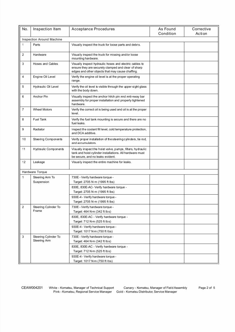
8/17/2019 Ce Aw 004101
http://slidepdf.com/reader/full/ce-aw-004101 260/265

8/17/2019 Ce Aw 004101
http://slidepdf.com/reader/full/ce-aw-004101 261/265
CEAW004201 White - Komatsu, Manager of Technical Support Canary - Komatsu, Manager of Field Assembly Page 3 of 5
Pink - Komatsu, Regional Service Manager Gold - Komatsu Distributor, Service Manager
4 Tie Rod Pin Retainer 730E - Verify hardware torque -
Target: 464 N·m (342 ft lbs)
830E, 830E-AC - Verify hardware torque -
Target: 712 N·m (525 ft lbs)
930E-4 - Verify hardware torque -
Target: 1017 N·m (750 ft l bs)
5 Front Brake Caliper
Mounting
(Capscrew with Nut)
730E - Verify hardware torque -
Target: 1085 N·m (800 ft l bs)
830E, 830E-AC - Verify hardware torque -
Target: 1085 N·m (800 ft l bs)
6 Front Brake Caliper
Mounting
(Capscrew Only)
730E - Verify hardware torque -
Target: 1166 N·m (860 ft lbs)
830E, 830E-AC - Verify hardware torque -
Target: 1166 N·m (860 ft lbs)
7 Rear Service Brake
Caliper Mounting
730E - Verify hardware torque -
Target: 780 N·m (575 ft lbs)
830E, 830E-AC - Verify hardware torque -
Target: 780 N·m (575 ft lbs)
8 Rear Brake Adapter
Mounting
730E - Verify hardware torque -
Target: 488 N·m (360 ft lbs)
830E, 830E-AC - Verify hardware torque -
Target: 488 N·m (360 ft lbs)
9 Brake Disc To Adapter
Mounting
730E - Verify hardware torque -
Target: 278 N·m (205 ft lbs)
830E, 830E-AC - Verify hardware torque -
Target: 278 N·m (205 ft lbs)
Cab Compartment
1 Horn Check for proper tone and volume. Ensure there is no
looseness in the horn button.
2 Back Up Horn Check for proper tone, volume, and function.
3 Gauges Verify all gauges are installed straight and are operating
correctly.
4 Glass Verify no cracks exist on cab windows. Ensure all win-
dows are properly sealed.
5 Seat/Seat belts Verify the cab seats and seat belts are in proper working
condition.
No. Inspection Item Acceptance Procedures As Found
Condition
Corrective
Acti on
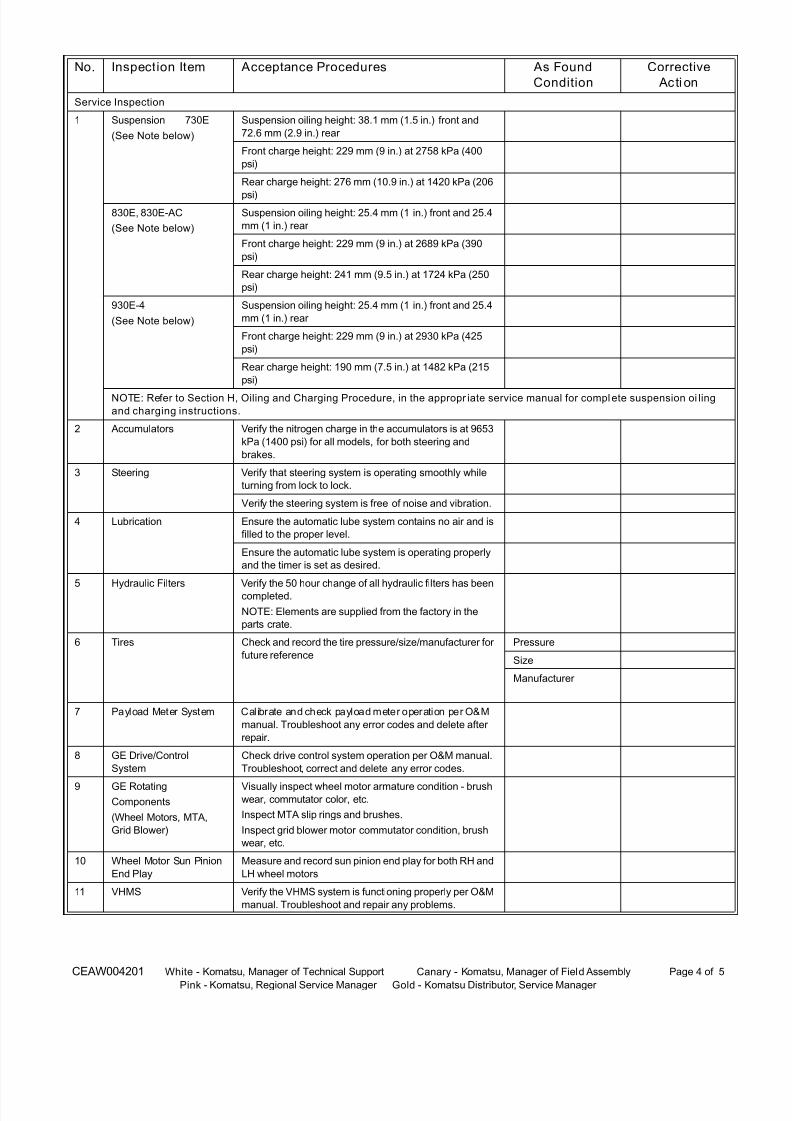
8/17/2019 Ce Aw 004101
http://slidepdf.com/reader/full/ce-aw-004101 262/265
CEAW004201 White - Komatsu, Manager of Technical Support Canary - Komatsu, Manager of Field Assembly Page 4 of 5
Pink - Komatsu, Regional Service Manager Gold - Komatsu Distributor, Service Manager
Service Inspection
1 Suspension 730E
(See Note below)
Suspension oiling height: 38.1 mm (1.5 in.) front and
72.6 mm (2.9 in.) rear
Front charge height: 229 mm (9 in.) at 2758 kPa (400
psi)
Rear charge height: 276 mm (10.9 in.) at 1420 kPa (206
psi)
830E, 830E-AC
(See Note below)
Suspension oiling height: 25.4 mm (1 in.) front and 25.4
mm (1 in.) rear
Front charge height: 229 mm (9 in.) at 2689 kPa (390
psi)
Rear charge height: 241 mm (9.5 in.) at 1724 kPa (250
psi)
930E-4
(See Note below)
Suspension oiling height: 25.4 mm (1 in.) front and 25.4
mm (1 in.) rear
Front charge height: 229 mm (9 in.) at 2930 kPa (425
psi)
Rear charge height: 190 mm (7.5 in.) at 1482 kPa (215
psi)
NOTE: Refer to Section H, Oiling and Charging Procedure, in the appropr iate service manual for complete suspension oi ling
and charging instructions.
2 Accumulators Verify the nitrogen charge in the accumulators is at 9653
kPa (1400 psi) for all models, for both steering and
brakes.
3 Steering Verify that steering system is operating smoothly while
turning from lock to lock.
Verify the steering system is free of noise and vibration.
4 Lubrication Ensure the automatic lube system contains no air and is
filled to the proper level.
Ensure the automatic lube system is operating properly
and the timer is set as desired.
5 Hydraulic Filters Verify the 50 hour change of all hydraulic filters has been
completed.
NOTE: Elements are supplied from the factory in the
parts crate.
6 Tires Check and record the tire pressure/size/manufacturer for
future reference
Pressure
Size
Manufacturer
7 Payload Meter System Calibrate and check payload meter operation per O&M
manual. Troubleshoot any error codes and delete after
repair.
8 GE Drive/Control
System
Check drive control system operation per O&M manual.
Troubleshoot, correct and delete any error codes.
9 GE RotatingComponents
(Wheel Motors, MTA,
Grid Blower)
Visually inspect wheel motor armature condition - brushwear, commutator color, etc.
Inspect MTA slip rings and brushes.
Inspect grid blower motor commutator condition, brush
wear, etc.
10 Wheel Motor Sun Pinion
End Play
Measure and record sun pinion end play for both RH and
LH wheel motors
11 VHMS Verify the VHMS system is functioning properly per O&M
manual. Troubleshoot and repair any problems.
No. Inspection Item Acceptance Procedures As Found
Condition
Corrective
Acti on

8/17/2019 Ce Aw 004101
http://slidepdf.com/reader/full/ce-aw-004101 263/265
CEAW004201 White - Komatsu, Manager of Technical Support Canary - Komatsu, Manager of Field Assembly Page 5 of 5
Pink - Komatsu, Regional Service Manager Gold - Komatsu Distributor, Service Manager
MINE OPTIONS - List any mine/site specifi c options or modifi cations made to the unit.
ADDITIONAL COMMENTS: ______________________________________________________________
__________________________________________________________________________________
__________________________________________________________________________________
__________________________________________________________________________________
__________________________________________________________________________________
No. Description of Modification Reason For Installation
1
2
3
4
5
6

8/17/2019 Ce Aw 004101
http://slidepdf.com/reader/full/ce-aw-004101 264/265

8/17/2019 Ce Aw 004101
http://slidepdf.com/reader/full/ce-aw-004101 265/265