Acier d armature inoxydable Top 12 Une nouvelle esthétique ...
3
4
5
6
7
8
9
10
11
13
12
1
14info
15index
2
2.1HYDROFLEX HYDRAULICS B.V.t. +31 (0)186 620777f. +31 (0)186 616007e. [email protected]
HYDROFLEX HYDRAULICS BELGIUM N.V.t. +32 (0)2 2674114f. +32 (0)2 2674225e. [email protected]
HYDROFLEX HYDRAULICS ROTTERDAM B.V.t. +31 (0)10 2839000f. +31 (0)10 4952590e. [email protected]
STAAL REF.ACIER 1090STEEL 1091STAHL 1590
2.3
RVS 316L REF.INOX 316L 1091STAINLESS STEEL 316L 1091ROSTFREI STAHL 316L 1590
2.5
ALGEMENE INFORMATIEINFORMATIONS GÉNÉRALES
GENERAL INFORMATION
2.8
MONTAGEVOORSCHIFTEN INSTRUCTIONS DE MONTAGE
ASSEMBLY INSTRUCTIONS
2.10
2
2.2HYDROFLEX HYDRAULICS B.V.
t. +31 (0)186 620777f. +31 (0)186 616007
HYDROFLEX HYDRAULICS BELGIUM N.V.t. +32 (0)2 2674114f. +32 (0)2 2674225
HYDROFLEX HYDRAULICS ROTTERDAM B.V.t. +31 (0)10 2839000f. +31 (0)10 4952590
1
2
2.3HYDROFLEX HYDRAULICS B.V.t. +31 (0)186 620777f. +31 (0)186 616007e. [email protected]
HYDROFLEX HYDRAULICS BELGIUM N.V.t. +32 (0)2 2674114f. +32 (0)2 2674225e. [email protected]
HYDROFLEX HYDRAULICS ROTTERDAM B.V.t. +31 (0)10 2839000f. +31 (0)10 4952590e. [email protected]
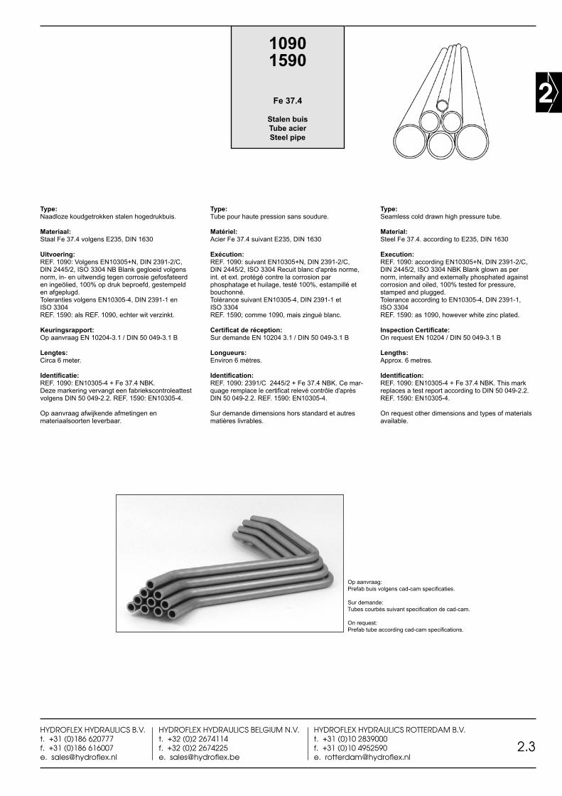
Type:Naadloze koudgetrokken stalen hogedrukbuis.
Materiaal:Staal Fe 37.4 volgens E235, DIN 1630
Uitvoering:REF. 1090: Volgens EN10305+N, DIN 2391-2/C, DIN 2445/2, ISO 3304 NB Blank gegloeid volgens norm, in- en uitwendig tegen corrosie gefosfateerd en ingeölied, 100% op druk beproefd, gestempeld en afgeplugd. Toleranties volgens EN10305-4, DIN 2391-1 en ISO 3304 REF. 1590: als REF. 1090, echter wit verzinkt.
Keuringsrapport:Op aanvraag EN 10204-3.1 / DIN 50 049-3.1 B
Lengtes:Circa 6 meter.
Identificatie:REF. 1090: EN10305-4 + Fe 37.4 NBK. Deze markering vervangt een fabriekscontroleattest volgens DIN 50 049-2.2. REF. 1590: EN10305-4.
Op aanvraag afwijkende afmetingen en materiaalsoorten leverbaar.
Type:Tube pour haute pression sans soudure.
Matériel:Acier Fe 37.4 suivant E235, DIN 1630
Exécution:REF. 1090: suivant EN10305+N, DIN 2391-2/C, DIN 2445/2, ISO 3304 Recuit blanc d'après norme, int. et ext. protégé contre la corrosion par phosphatage et huilage, testé 100%, estampillé et bouchonné.Tolérance suivant EN10305-4, DIN 2391-1 et ISO 3304 REF. 1590; comme 1090, mais zingué blanc.
Certificat de réception:Sur demande EN 10204 3.1 / DIN 50 049-3.1 B
Longueurs:Environ 6 mètres.
Identification:REF. 1090: 2391/C 2445/2 + Fe 37.4 NBK. Ce mar-quage remplace le certificat relevé contrôle d'après DIN 50 049-2.2. REF. 1590: EN10305-4.
Sur demande dimensions hors standard et autres matières livrables.
Type:Seamless cold drawn high pressure tube.
Material:Steel Fe 37.4. according to E235, DIN 1630
Execution:REF. 1090: according EN10305+N, DIN 2391-2/C, DIN 2445/2, ISO 3304 NBK Blank glown as per norm, internally and externally phosphated against corrosion and oiled, 100% tested for pressure, stamped and plugged. Tolerance according to EN10305-4, DIN 2391-1, ISO 3304REF. 1590: as 1090, however white zinc plated.
Inspection Certificate:On request EN 10204 / DIN 50 049-3.1 B
Lengths:Approx. 6 metres.
Identification:REF. 1090: EN10305-4 + Fe 37.4 NBK. This mark replaces a test report according to DIN 50 049-2.2.REF. 1590: EN10305-4.
On request other dimensions and types of materials available.
Op aanvraag: Prefab buis volgens cad-cam specificaties.
Sur demande: Tubes courbés suivant specification de cad-cam.
On request: Prefab tube according cad-cam specifications.
10901590
Fe 37.4
Stalen buisTube acierSteel pipe

2
2.4HYDROFLEX HYDRAULICS B.V.
t. +31 (0)186 620777f. +31 (0)186 616007
HYDROFLEX HYDRAULICS BELGIUM N.V.t. +32 (0)2 2674114f. +32 (0)2 2674225
HYDROFLEX HYDRAULICS ROTTERDAM B.V.t. +31 (0)10 2839000f. +31 (0)10 4952590
REF.
mm mm BAR BAR1) BAR g/m Fe/P 37.4 Fe/Zn 37.44 0,5 266 404 953 43 1090-04x0,52)
4 1 629 955 2253 70 1590-04x1,06 1 377 558 1320 123 1090-06x1,02) 1590-06x1,06 1,5 565 792 2145 167 1090-06x1,52) 1590-06x1,56 2 754 995 3120 197 1090-06x2,02) 1590-06x2,08 1 282 430 953 173 1090-08x1,0 1590-08x1,08 1,5 424 619 1514 240 1090-08x1,5 1590-08x1,58 2 565 792 2145 296 1090-08x2,0 1590-10x2,0
10 1 239 370 746 222 1090-10x1,0 1590-10x1,010 1,5 359 538 1170 314 1090-10x1,5 1590-10x1,510 2 479 694 1634 395 1090-10x2,012 1 199 308 612 271 1090-12x1,0 1590-12x1,012 1,5 299 455 953 389 1090-12x1,5 1590-12x1,512 2 399 591 1320 493 1090-12x2,0 1590-12x2,012 3 598 838 2145 670 1090-12x3,014 1,5 256 394 804 462 1090-14x1,5 1590-14x1,514 2 342 514 1107 592 1090-14x2,0 1590-14x2,014 2,5 427 628 1430 709 1090-14x2,5 1590-14x2,515 1,5 239 370 746 499 1090-15x1,5 1590-15x1,515 2 319 483 1024 641 1090-15x2,0 1590-15x2,016 1,5 224 347 695 536 1090-16x1,5 1590-16x1,516 2 299 455 953 691 1090-16x2,0 1590-16x2,016 2,5 374 558 1225 832 1090-16x2,5 1590-16x2,516 3 449 656 1514 961 1090-16x3,018 1,5 199 308 612 610 1090-18x1,5 1590-18x1,518 2 266 408 837 789 1090-18x2,0 1590-18x2,018 3 399 591 1320 1110 1090-18x3,020 1,5 179 277 547 684 1090-20x1,520 2 239 370 746 888 1090-20x2,0 1590-20x2,020 2,5 299 455 953 1079 1090-20x2,5 1590-20x2,520 3 359 538 1170 1258 1090-20x3,0 1590-20x3,020 4 479 694 1634 1578 1090-20x4,022 1,5 163 252 495 758 1090-22x1,5 1590-22x1,522 2 217 336 673 986 1090-22x2,0 1590-22x2,022 2,5 272 417 858 1200 1090-22x2,522 3 326 493 1050 1410 1090-22x3,025 1,5 143 222 432 869 1590-25x1,525 2 191 296 586 1130 1090-25x2,0 1590-25x2,025 2,5 239 370 746 1387 1090-25x2,5 1590-25x2,525 3 287 438 911 1628 1090-25x3,0 1590-25x3,025 4 399 595 1259 2072 1090-25x4,0 1590-25x4,028 1,5 128 198 384 980 1090-28x1,5 1590-28x1,528 2 171 264 520 1282 1090-28x2,0 1590-28x2,028 2,5 213 330 660 1572 1090-28x2,5 1590-28x2,528 3 256 394 804 1850 1090-28x3,0 1590-28x3,028 4 537 826 1686 2370 1090-28x4,030 2 159 246 483 2381 1090-30x2,030 2,5 199 308 612 1696 1090-30x2,5 1590-30x2,530 3 239 370 746 1998 1090-30x3,0 1590-30x3,030 4 333 504 1024 2565 1090-30x4,0 1590-30x4,030 5 416 617 1320 3080 1090-30x5,035 2 142 220 411 1628 1090-35x2,0 1590-35x2,035 2,5 178 275 520 2000 1090-35x2,5 1590-35x3,035 3 214 331 631 2368 1090-35x3,035 4 285 437 863 3058 1090-35x4,035 5 357 537 1107 3700 1090-35x5,038 2,5 164 254 476 2190 1090-38x2,538 3 197 305 578 2590 1090-38x3,038 4 263 405 789 3354 1090-38x4,0 1590-38x4,038 5 328 498 1009 4069 1090-38x5,0 1590-38x5,042 2 119 183 339 1970 1090-42x2,0 1590-42x2,042 3 171 264 520 2886 1090-42x3,0 1590-42x3,042 4 238 367 707 3750 1090-42x4,0 1590-42x4,042 5 297 454 903 4560 1090-42x5,048 5 260 401 780 5300 1090-48x5,050 3 149 231 432 3480 1090-50x3,050 5 249 386 746 5548 1090-50x5,050 6 299 457 911 6510 1090-50x6,050 8 399 595 1259 8290 1090-50x8,050 10 499 724 1634 9860 1090-50x10,060 3 124 193 357 4220 1090-60x3,060 5 208 321 612 6780 1090-60x5,060 6 249 386 746 7990 1090-60x6,060 8 333 504 1024 10260 1090-60x8,065 8 307 468 937 11246 1090-65x8,0
1) Volgens DIN 2413, F=1,5 Suivant DIN 2413, F=1,5 According to DIN 2413, F=1,5
2) NIET gefosfateerd NE PAS phosphaté NOT phosphated
2
2.5HYDROFLEX HYDRAULICS B.V.t. +31 (0)186 620777f. +31 (0)186 616007e. [email protected]
HYDROFLEX HYDRAULICS BELGIUM N.V.t. +32 (0)2 2674114f. +32 (0)2 2674225e. [email protected]
HYDROFLEX HYDRAULICS ROTTERDAM B.V.t. +31 (0)10 2839000f. +31 (0)10 4952590e. [email protected]
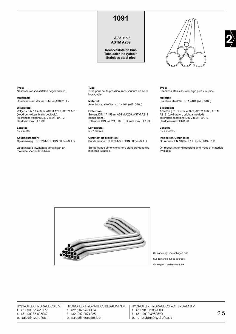
Type:Naadloze roestvaststalen hogedrukbuis
Materiaal:Roestvaststaal Ws. nr. 1.4404 (AISI 316L)
Uitvoering:Volgens DIN 17 458-m, ASTM A269, ASTM A213 (koud getrokken, blank gegloeid). Toleranties volgens DIN 2462/1, D4/T3, Hardheid max. HRB 90
Lengtes:5 - 7 meter.
Keuringsrapport:Op aanvraag EN 10204-3.1 / DIN 50 049-3.1 B
Op aanvraag afwijkende afmetingen en materiaalsoorten leverbaar.
Type:Tube pour haute pression sans soudure en acier inoxydable
Matériel:Acier inoxydable Ws. nr. 1.4404 (AISI 316L)
Exécution:Suivant DIN 17 458-m, ASTM A269, ASTM A213 (recuit blanc). Tolérance DIN 2462/1, D4/T3. Dureté max. HRB 90
Longueurs:5 - 7 mètres.
Certificat de réception:Sur demande EN 10204-3.1 / DIN 50 049-3.1 B
Sur demande dimensions hors standard et autres matières livrables.
Type:Seamless stainless steel high pressure pipe
Material:Stainless steel Ws. nr. 1.4404 (AISI 316L)
Execution:According to DIN 17 458-m, ASTM A269, ASTM A213 (cold drawn, bright annealed). Tolerance according DIN 2462/1, D4/T3, Hardness max. HRB 90
Lengths:5 - 7 metres.
Inspection Certificate:On request EN 10204-3.1 / DIN 50 049-3.1 B
On request other dimensions and types of materials available.
Op aanvraag: voorgebogen buis Sur demande: tubes courbés
On request: prebended tube
1091
AISI 316 L ASTM A269
Roestvaststalen buisTube acier inoxydable
Stainless steel pipe
2
2.6HYDROFLEX HYDRAULICS B.V.
t. +31 (0)186 620777f. +31 (0)186 616007
HYDROFLEX HYDRAULICS BELGIUM N.V.t. +32 (0)2 2674114f. +32 (0)2 2674225
HYDROFLEX HYDRAULICS ROTTERDAM B.V.t. +31 (0)10 2839000f. +31 (0)10 4952590
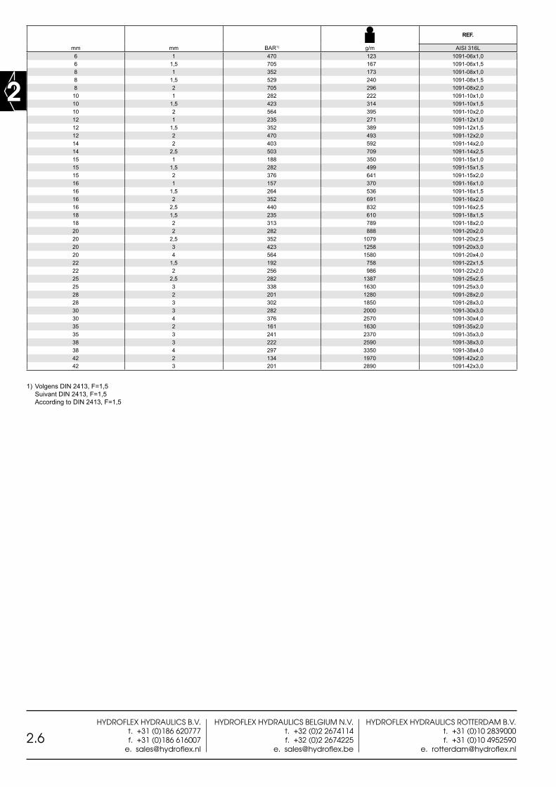
1) Volgens DIN 2413, F=1,5 Suivant DIN 2413, F=1,5 According to DIN 2413, F=1,5
REF.
mm mm BAR1) g/m AISI 316L6 1 470 123 1091-06x1,06 1,5 705 167 1091-06x1,58 1 352 173 1091-08x1,08 1,5 529 240 1091-08x1,58 2 705 296 1091-08x2,0
10 1 282 222 1091-10x1,010 1,5 423 314 1091-10x1,510 2 564 395 1091-10x2,012 1 235 271 1091-12x1,012 1,5 352 389 1091-12x1,512 2 470 493 1091-12x2,014 2 403 592 1091-14x2,014 2,5 503 709 1091-14x2,515 1 188 350 1091-15x1,015 1,5 282 499 1091-15x1,515 2 376 641 1091-15x2,016 1 157 370 1091-16x1,016 1,5 264 536 1091-16x1,516 2 352 691 1091-16x2,016 2,5 440 832 1091-16x2,518 1,5 235 610 1091-18x1,518 2 313 789 1091-18x2,020 2 282 888 1091-20x2,020 2,5 352 1079 1091-20x2,520 3 423 1258 1091-20x3,020 4 564 1580 1091-20x4,022 1,5 192 758 1091-22x1,522 2 256 986 1091-22x2,025 2,5 282 1387 1091-25x2,525 3 338 1630 1091-25x3,028 2 201 1280 1091-28x2,028 3 302 1850 1091-28x3,030 3 282 2000 1091-30x3,030 4 376 2570 1091-30x4,035 2 161 1630 1091-35x2,035 3 241 2370 1091-35x3,038 3 222 2590 1091-38x3,038 4 297 3350 1091-38x4,042 2 134 1970 1091-42x2,042 3 201 2890 1091-42x3,0
2
2.7HYDROFLEX HYDRAULICS B.V.t. +31 (0)186 620777f. +31 (0)186 616007e. [email protected]
HYDROFLEX HYDRAULICS BELGIUM N.V.t. +32 (0)2 2674114f. +32 (0)2 2674225e. [email protected]
HYDROFLEX HYDRAULICS ROTTERDAM B.V.t. +31 (0)10 2839000f. +31 (0)10 4952590e. [email protected]
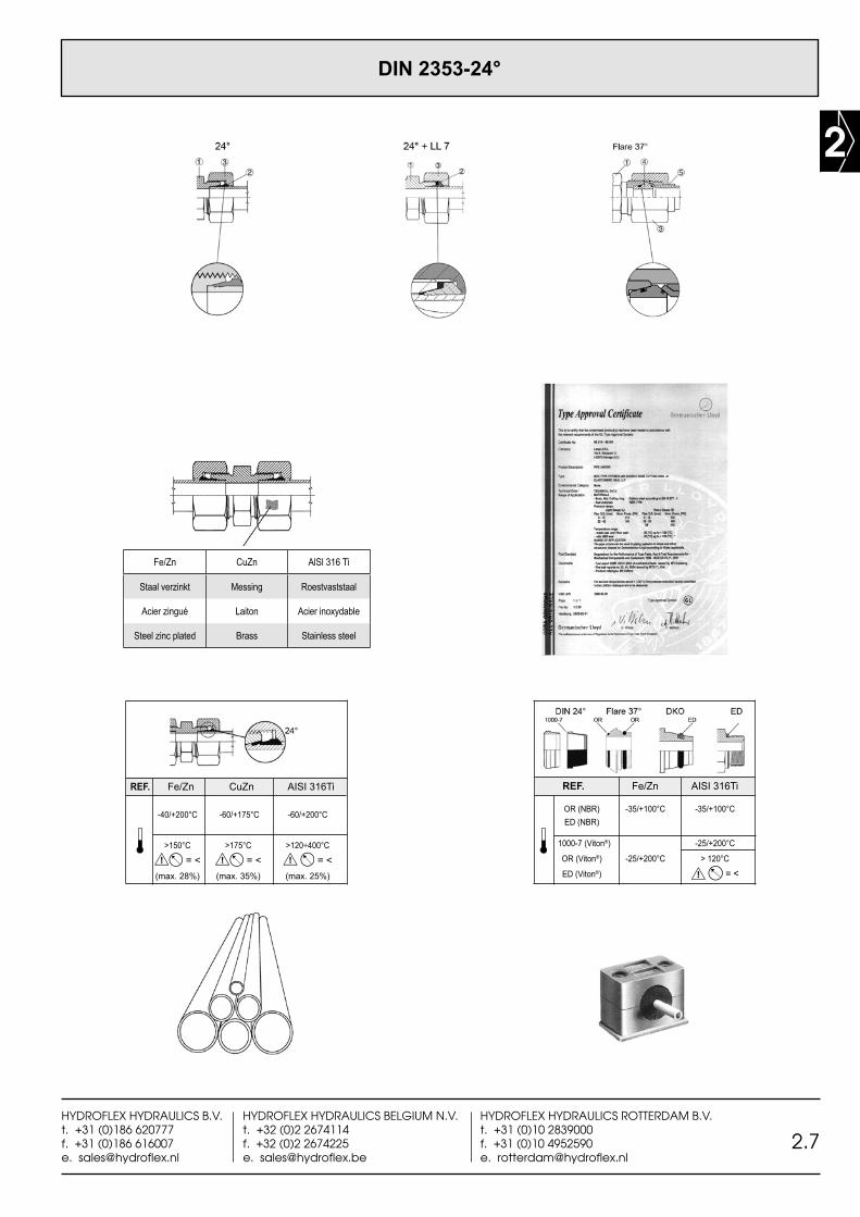
REF. Fe/Zn CuZn AISI 316Ti
-40/+200°C -60/+175°C -60/+200°C
>150°C >175°C >120÷400°C = < = < = < (max. 28%) (max. 35%) (max. 25%)
OR (NBR) -35/+100°C -35/+100°C ED (NBR)
1000-7 (Viton®) -25/+200°C
OR (Viton®) -25/+200°C > 120°C ED (Viton®) = <
REF. Fe/Zn AISI 316Ti
DIN 2353-24°
Fe/Zn CuZn AlSl 316 Ti
Staal verzinkt Messing Roestvaststaal
Acier zingué Laiton Acier inoxydable
Steel zinc plated Brass Stainless steel
2
2.8HYDROFLEX HYDRAULICS B.V.
t. +31 (0)186 620777f. +31 (0)186 616007
HYDROFLEX HYDRAULICS BELGIUM N.V.t. +32 (0)2 2674114f. +32 (0)2 2674225
HYDROFLEX HYDRAULICS ROTTERDAM B.V.t. +31 (0)10 2839000f. +31 (0)10 4952590
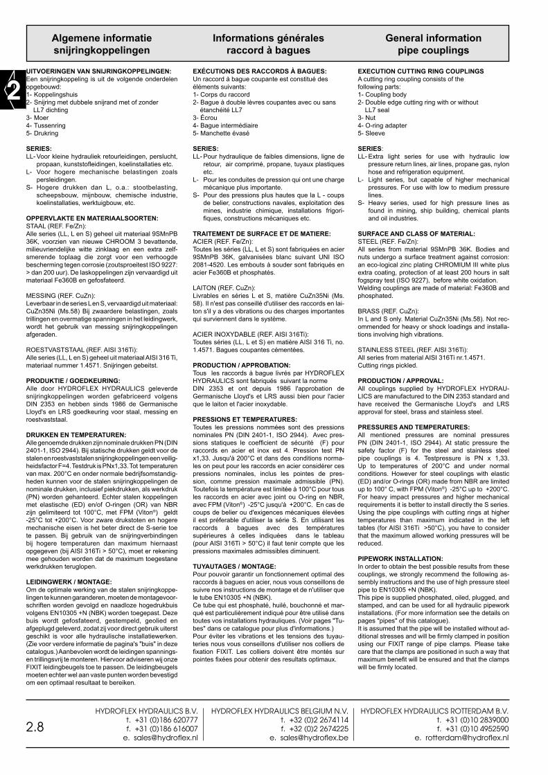
Algemene informatiesnijringkoppelingen
UITVOERINGEN VAN SNIJRINGKOPPELINGEN:Een snijringkoppeling is uit de volgende onderdelen opgebouwd:1- Koppelingshuis2- Snijring met dubbele snijrand met of zonder LL7 dichting3- Moer4- Tussenring5- Drukring
SERIES:LL- Voor kleine hydrauliek retourleidingen, perslucht,
propaan, kunststofleidingen, koelinstallaties etc.L- Voor hogere mechanische belastingen zoals
persleidingen.S- Hogere drukken dan L, o.a.: stootbelasting,
scheepsbouw, mijnbouw, chemische industrie, koelinstallaties, werktuigbouw, etc.
OPPERVLAKTE EN MATERIAALSOORTEN:STAAL (REF. Fe/Zn):Alle series (LL, L en S) geheel uit materiaal 9SMnPB 36K, voorzien van nieuwe CHROOM 3 bevattende, milieuvriendelijke witte zinklaag en een extra zelf-smerende toplaag die zorgt voor een verhoogde bescherming tegen corrosie (zoutsproeitest ISO 9227: > dan 200 uur). De laskoppelingen zijn vervaardigd uit materiaal Fe360B en gefosfateerd.
MESSING (REF. CuZn):Leverbaar in de series L en S, vervaardigd uit materiaal: CuZn35Ni (Ms.58) Bij zwaardere belastingen, zoals trillingen en overmatige spanningen in het leidingwerk, wordt het gebruik van messing snijringkoppelingen afgeraden.
ROESTVASTSTAAL (REF. AISI 316Ti):Alle series (LL, L en S) geheel uit materiaal AISI 316 Ti, materiaal nummer 1.4571. Snijringen gebeitst.
PRODUKTIE / GOEDKEURING:Alle door HYDROFLEX HYDRAULICS geleverde snijringkoppelingen worden gefabriceerd volgens DIN 2353 en hebben sinds 1986 de Germanische Lloyd's en LRS goedkeuring voor staal, messing en roestvaststaal.
DRUKKEN EN TEMPERATUREN:Alle genoemde drukken zijn nominale drukken PN (DIN 2401-1, ISO 2944). Bij statische drukken geldt voor de stalen en roestvaststalen snijringkoppelingen een veilig-heidsfactor F=4. Testdruk is PNx1,33. Tot temperaturen van max. 200°C en onder normale bedrijfsomstandig-heden kunnen voor de stalen snijringkoppelingen de nominale drukken, inclusief piekdrukken, als werkdruk (PN) worden gehanteerd. Echter stalen koppelingen met elastische (ED) en/of O-ringen (OR) van NBR zijn gelimiteerd tot 100°C, met FPM (Viton®) geldt -25°C tot +200°C. Voor zware drukstoten en hogere mechanische eisen is het beter direct de S-serie toe te passen. Bij gebruik van de snijringverbindingen bij hogere temperaturen dan maximum hiernaast opgegeven (bij AISI 316Ti > 50°C), moet er rekening mee gehouden worden dat de maximum toegestane werkdrukken teruglopen.
LEIDINGWERK / MONTAGE:Om de optimale werking van de stalen snijringkoppe-lingen te kunnen garanderen, moeten de montagevoor-schriften worden gevolgd en naadloze hogedrukbuis volgens EN10305 +N (NBK) worden toegepast. Deze buis wordt gefosfateerd, gestempeld, geolied en afgeplugd geleverd, zodat zij voor direct gebruik uiterst geschikt is voor alle hydraulische installatiewerken. (Zie voor verdere informatie de pagina's "buis" in deze catalogus.) Aanbevolen wordt de leidingen spannings- en trillingsvrij te monteren. Hiervoor adviseren wij onze FIXIT leidingbeugels toe te passen. De leidingbeugels moeten echter wel aan vaste punten worden bevestigd om een optimaal resultaat te bereiken.
Informations généralesraccord à bagues
EXÉCUTIONS DES RACCORDS À BAGUES:Un raccord à bague coupante est constitué des éléments suivants:1- Corps du raccord2- Bague à double lèvres coupantes avec ou sans étanchéité LL73- Écrou4- Bague intermédiaire5- Manchette évasé
SERIES:LL- Pour hydraulique de faibles dimensions, ligne de
retour, air comprimé, propane, tuyaux plastiques etc.
L- Pour les conduites de pression qui ont une charge mécanique plus importante.
S- Pour des pressions plus hautes que la L - coups de belier, constructions navales, exploitation des mines, industrie chimique, installations frigori-fiques, constructions mécaniques etc.
TRAITEMENT DE SURFACE ET DE MATIERE:ACIER (REF. Fe/Zn):Toutes les séries (LL, L et S) sont fabriquées en acier 9SMnPB 36K, galvanisées blanc suivant UNI ISO 2081-4520. Les embouts à souder sont fabriqués en acier Fe360B et phosphatés.
LAITON (REF. CuZn):Livrables en séries L et S, matière CuZn35Ni (Ms. 58). Il n'est pas conseillé d'utiliser des raccords en lai-ton s'il y a des vibrations ou des charges importantes qui surviennent dans le système.
ACIER INOXYDABLE (REF. AISI 316Ti):Toutes séries (LL, L et S) en matière AISI 316 Ti, no. 1.4571. Bagues coupantes cémentées.
PRODUCTION / APPROBATION:Tous les raccords à bague livrés par HYDROFLEX HYDRAULICS sont fabriqués suivant la norme DIN 2353 et ont depuis 1986 l'approbation de Germanische Lloyd's et LRS aussi bien pour l'acier que le laiton et l'acier inoxydable.
PRESSIONS ET TEMPERATURES:Toutes les pressions nommées sont des pressions nominales PN (DIN 2401-1, ISO 2944). Avec pres-sions statiques le coefficient de sécurité (F) pour raccords en acier et inox est 4. Pression test PN x1,33. Jusqu'à 200°C et dans des conditions norma-les on peut pour les raccords en acier considérer ces pressions nominales, inclus les pointes de pres-sion, comme pression maximale admissible (PN). Toutefois la température est limitée à 100°C pour tous les raccords en acier avec joint ou O-ring en NBR, avec FPM (Viton®) -25°C jusqu'à +200°C. En cas de coups de belier ou d'exigences mécaniques élevées il est préferable d'utiliser la série S. En utilisant les raccords à bagues avec des températures supérieures à celles indiquées dans le tableau (pour AISI 316Ti > 50°C) il faut tenir compte que les pressions maximales admissibles diminuent.
TUYAUTAGES / MONTAGE:Pour pouvoir garantir un fonctionnement optimal des raccords à bagues en acier, nous vous conseillons de suivre nos instructions de montage et de n'utiliser que le tube EN10305 +N (NBK).Ce tube qui est phosphaté, huilé, bouchonné et mar-qué est particulièrement indiqué pour être utilisé dans toutes vos installations hydrauliques. (Voir pages "Tu-bes" dans ce catalogue pour plus d'informations.) Pour éviter les vibrations et les tensions des tuyau-teries nous vous conseillons d'utiliser nos colliers de fixation FIXIT. Les colliers doivent être montés sur pointes fixées pour obtenir des resultats optimaux.
General informationpipe couplings
EXECUTION CUTTING RING COUPLINGSA cutting ring coupling consists of the following parts:1- Coupling body2- Double edge cutting ring with or without LL7 seal3- Nut4- O-ring adapter5- Sleeve
SERIES:LL- Extra light series for use with hydraulic low
pressure return lines, air lines, propane gas, nylon hose and refrigeration equipment.
L- Light series, but capable of higher mechanical pressures. For use with low to medium pressure lines.
S- Heavy series, used for high pressure lines as found in mining, ship building, chemical plants and oil industries.
SURFACE AND CLASS OF MATERIAL:STEEL (REF. Fe/Zn):All series from material 9SMnPB 36K. Bodies and nuts undergo a surface treatment against corrosion: an eco-logical zinc plating CHROMIUM III white plus extra coating, protection of at least 200 hours in salt fogspray test (ISO 9227), before white oxidation.Welding couplings are made of material: Fe360B and phosphated.
BRASS (REF. CuZn):In L and S only. Material CuZn35Ni (Ms.58). Not rec-ommended for heavy or shock loadings and installa-tions involving high vibrations.
STAINLESS STEEL (REF. AISI 316Ti):All series from material AISI 316Ti nr.1.4571. Cutting rings pickled.
PRODUCTION / APPROVAL:All couplings supplied by HYDROFLEX HYDRAU-LICS are manufactured to the DIN 2353 standard and have received the Germanische Lloyd's and LRS approval for steel, brass and stainless steel.
PRESSURES AND TEMPERATURES:All mentioned pressures are nominal pressures PN (DIN 2401-1, ISO 2944). At static pressure the safety factor (F) for the steel and stainless steel pipe couplings is 4. Testpressure is PN x 1,33. Up to temperatures of 200°C and under normal conditions. However for steel couplings with elastic (ED) and/or O-rings (OR) made from NBR are limited up to 100° C, with FPM (Viton®) -25°C up to +200°C. For heavy impact pressures and higher mechanical requirements it is better to install directly the S series. Using the pipe couplings with cutting rings at higher temperatures than maximum indicated in the left tables (for AISI 316Ti >50°C), you have to consider that the maximum allowed working pressures will be reduced.
PIPEWORK INSTALLATION:In order to obtain the best possible results from these couplings, we strongly recommend the following as-sembly instructions and the use of high pressure steel pipe to EN10305 +N (NBK). This pipe is supplied phosphated, oiled, plugged, and stamped, and can be used for all hydraulic pipework installations. (For more information see the details on pages "pipes" of this catalogue).It is assumed that the pipe will be installed without ad-ditional stresses and will be firmly clamped in position using our FIXIT range of pipe clamps. Please take care that the clamps are positioned in such a way that maximum benefit will be ensured and that the clamps will be firmly located.
2
2.9HYDROFLEX HYDRAULICS B.V.t. +31 (0)186 620777f. +31 (0)186 616007e. [email protected]
HYDROFLEX HYDRAULICS BELGIUM N.V.t. +32 (0)2 2674114f. +32 (0)2 2674225e. [email protected]
HYDROFLEX HYDRAULICS ROTTERDAM B.V.t. +31 (0)10 2839000f. +31 (0)10 4952590e. [email protected]
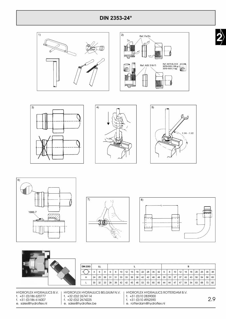
DIN 2353 LL L S
4 6 8 6 8 10 12 15 18 22 28 35 42 6 8 10 12 14 16 20 25 30 38
H 24 25 26 31 31 33 33 36 38 42 42 48 48 35 35 37 37 43 43 50 54 58 65
L 30 32 33 39 39 42 42 45 48 53 53 60 60 44 44 47 47 54 54 63 68 73 82
DIN 2353-24°
2
2.10HYDROFLEX HYDRAULICS B.V.
t. +31 (0)186 620777f. +31 (0)186 616007
HYDROFLEX HYDRAULICS BELGIUM N.V.t. +32 (0)2 2674114f. +32 (0)2 2674225
HYDROFLEX HYDRAULICS ROTTERDAM B.V.t. +31 (0)10 2839000f. +31 (0)10 4952590
Montagevoorschiften voorsnijringkoppelingen
1) De buis haaks afzagen, bramen aan de binnen- en buitenzijde verwijderen en goed schoonmaken.Het gebruik van een pijpsnijder wordt afgeraden omdat dit een schuin snijvlak met veel braamvorming oplevert. Voor een optimale werking van de verbinding dient een volledig contact tussen het uiteinde van de buis en de aanslag in de koppeling aanwezig te zijn.
2) Draad en konus, snijring en wartelmoer aan binnenzijde goed oliën. Voor de montage van roestvaststalen snijringkoppelingen moet er "anti-blok" vet gebruikt worden om het invreten van de wartelmoer op de draadstukken te voorkomen.
3)Eerst de wartelmoer dan snijring op de buis schui-ven. De snijring dient met de verdikte kant naar de wartelmoer gericht te zijn, zodat de konus met de insnijdende kant in de konus van de koppeling valt.
4)De buis in het draadstuk schuiven en vervolgens de wartelmoer handvast aandraaien.Let erop dat de buis goed tegen de aanslag van de koppeling drukt.
5)Wartelmoer met een sleutel circa 1.1/4-1.1/2 slag aandraaien waarbij de buis niet mag meedraaien. Door een markering op de buis en wartelmoer aan te brengen, kan men nauwkeurig controleren of de voorgeschreven omwentelingen bereikt worden.
Let op: voor verbindingen met vaste konus en "O-ring" afdichting de moer max. 1/4-1/2 slag aantrekken.
6)Controle:Wartelmoer losdraaien waarna de insnijding duide-lijk zichtbaar moet zijn en de snijring moet volledig deze gemaakte insnijding vullen. De snijring mag eventueel wel te draaien zijn, echter niet voor- of achteruit geschoven kunnen worden. Bij toepassing van de LL7 elastische dichting, deze nu over de voorgemonteerde snijring schuiven.
7)Eind- of hermontage:Na het demonteren dient bij hermontage de wartelmoer zonder te veel verhoogde kracht te worden aangedraaid. Bij montage na voormontage, dient de wartelmoer nog minimaal een 1/2 slag te worden aangedraaid na de voelbaar verhoogde weerstand. Dit laatste geldt dus ook voor standaard voorgemonteerde instelbare koppelingen. Ook deze koppelingen bij montage goed oliën.
8)Bij de montage van snijringkoppelingen moet voor rechte buis de minimum maat "L" en voor bochten de minimum maat "H" in acht worden genomen.
Instructions de montage pour raccord à bagues
1)Couper le tube à angle droit, nettoyer et ébavurer le tube à l’extérieur et à l’intérieur. De préférence ne pas utiliser de coupe-tube car la face de coupe n’est pas droite et il y a beaucoup de bavures qui se créent. Pour obtenir un montage parfait il faut un maximum de contact entre le tube et la butée du raccord.
2)Huiler la bague coupante, l’écrou, la partie filetée du raccord et le cône 24 degrés.Pour le montage des raccords en acier inox il est nécessaire d’utiliser une graisse “anti-blocage” pour éviter le grippage des écrous.
3)Glisser l’écrou sur le tube, puis la bague coupante avec le coté le plus épais vers l’écrou, de façon que le cône avec face coupante tombe dans le cône de la pièce filetée.
4)Le tube en appui, visser l’écrou à la main jusqu’au blocage.
5)Serrer l’écrou 1.1/4-1.1/2 tours à l’aide d’une clef adéquate en évitant toute rotation de tube pendant le serrage. Un marquage sur le corps de raccord ainsi que sur l’écrou vous permet de contrôler si le 1.1/4-1.1/2 tours ont été obtenus.
Attention: pour les nouveaux raccords avec cône fixe et joint torique serrer l'écrou maximum 1/4-1/2 de tour.
6)Contrôle:Dévisser l’écrou, l’incision de la bague dans le tube doit être visible. La bague coupante peut tourner sur son axe, par contre elle ne peut pas glisser en arrière ou en avant.En cas d'application de la bague coupante avec le joint elastique LL7, monter le joint elastique sur la bague coupante prémonter.
7)Montage définitif:Le montage définitif après prémontage doit se faire avec ± 1/2 tour de l’écrou après que l’on ait res-senti une résistance au montage. Ceci est également valable pour des raccords livrés prémontés. Ces raccords doivent également être huilés avant le montage définitif. Quand un raccord qui a été définitivement monté, et demonté, il faut veiller à ne pas trop forcer l’écrou lors du remontage.
8)Pour le montage de raccords à bague coupante il faut tenir compte de la dimension minimum "L" pour les tubes droits et avec la dimension minimum "H" pour les tubes coudés.
Assembly instructions cutting ring couplings
1)Cut the pipe right angled and lightly debur inside and outside, remove all dirt and swarf. Do not use a pipe cutter because the wall of the pipe will not be right angled and swarf will also be created. For a good connection it is necessary that there is a total contact between the tube end and the abutment in the couplingbody.
2)Oil all threads, cutting ring and inner cone of stud. (This facilitates assembly). To avoid damage of the thread and easier assembling of stainless steel couplings, you should use "anti-block" grease.
3)Place the nut and cutting ring on the pipe. Ensure that the thicker end of the ring is facing the nut.
4)Push the pipe into the coupling body, be sure that the end of the pipe is touching the stop at the bottom of the cone. Tighten the nut by hand as much as possible.
5)Tighten the nut by a spanner ± 1.1/4-1.1/2 turn, the pipe may not turn during the tightening. To be sure that you are reaching the prescribed turns it is necessary to mark the pipe and the nut.
Attention: for connections with pre-mounted cutting ring, solid cone and "O-ring" sealing fasten the nut maximum 1/4 till 1/2 turn.
6)Check:Loosen the nut and break assembly. Check if the cutting ring has caused a cutting edge. A visible collar must fill out the space in front of the cutting ring. Check that the ring is held firmly in place and does not slide along the pipe; a slight rotation is permitted. When using the LL7 soft seal, place the elastic seal over the premounted cutting ring.
7)Final- and re-assembly:After dismantling, the nut must be re-tightened without using excessive force.The nut of a pre-assembled coupling must be tightened minimum 1/2 turn after feeling the perceptible resistance. This goes also for standard pre-assembled couplings which also must be oiled before assembling.
8)Please take notice of the fact that for the assembly of cuttting ring couplings for straight tubes a mini-mum size "L" and for corners a minimum size "H" is necessary
2
2.11HYDROFLEX HYDRAULICS B.V.t. +31 (0)186 620777f. +31 (0)186 616007e. [email protected]
HYDROFLEX HYDRAULICS BELGIUM N.V.t. +32 (0)2 2674114f. +32 (0)2 2674225e. [email protected]
HYDROFLEX HYDRAULICS ROTTERDAM B.V.t. +31 (0)10 2839000f. +31 (0)10 4952590e. [email protected]
DIN 3949 DIN 2353
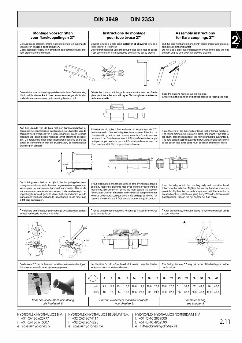
Montage voorschriftenvoor flarekoppelingen 37°
Instructions de montagepour tube évasé 37°
Assembly instructionsfor flare couplings 37°
De buis haaks afzagen, bramen aan de binnen- en buitenzijde verwijderen en goed schoonmaken. Geen pijpsnijder gebruiken omdat dit een schuin snijvlak met veel braamvorming oplevert.
Couper le tube à angle droit, nettoyer et ébavurer le tube à l’extérieur et à l’intérieur. De préférence ne pas utiliser de coupe-tube car la face de coupe n’est pas droite et il y a beaucoup de bavures qui se créent.
Cut the pipe right angled and lightly debur inside and outside, remove all dirt and swarf. Do not use a pipe cutter because the wall of the pipe will not be right angled and swarf will also be created.
De wartelmoer en tussenring op de buis schuiven. De tussenring dient met de dunne kant naar de wartelmoer gericht te zijn, zodat de wartelmoer over de tussenring heen schuift.
Glisser l’écrou sur le tube, puis la manchette avec le côté le plus petit vers l’écrou afin que l'écrou glisse au-dessus de la manchette.
Slide the nut and flare sleeve on the pipe. Ensure that the thinner end of the sleeve is facing the nut.
Aan het uiteinde van de buis met een flaregereedschap of flaremachine een flarerand aanbrengen. De diameter van de flarerand wordt weergegeven in tabel. Belangrijk: bij een te kleine flarerand zal geen goede montage en/of afdichting mogelijk zijn. De flarekonus moet tijdens het flaren haaks op de buisas staan en concentrisch met de drukring zijn, de binnenkonus braamvrij en schoon.
A l'extrémité du tube il faut exécuter un évasement de 37°. Le diamètre du cône est indiquées dans tableau. Attention: un cône évasé trop petit ne peut pas assurer un bon fonctionnement du raccord.Le cône d'évasement doit être parfaitement en angle droit par rapport au tube pendant l'opération d'évasement. Le cône intérieur doit être propre et sans bavure.
Flare the end of the tube with a flaring tool or flaring machine. The flaring diameters are given in table. Important: if the flare is too short, proper operation of the fitting cannot be guaranteed. The flare cone must be square to the tubular axle and concentric to the collar. The inner cone must be clean and free of flutes.
De drukring met cilindrische zijde in het koppelingshuis aan-brengen en de buis met de flarerand tegen de drukring plaatsen. Vervolgens de wartelmoer handvast aandraaien. Hierna de wartelmoer met een sleutel aandraaien zodat de drukring in het koppelingshuis wordt gedrukt. Als er bij het aandraaien van de wartelmoer voelbaar verhoogde kracht nodig is, de moer nog ± 1/4 slag aandraaien.
Il faut introduire la manchette avec le côté cylindrique dans le corps du raccord et placer le tube avec le cône évasé contre la manchette. Ensuite serrer l'écrou à la main et alors il faut serrer l'écrou avec une clef afin que la manchette soit comprimée dans le corps du raccord. Lorsque pendant le serrage de l'écrou l'on ressent une résistance il faut encore tourner un quart de tour.
Insert the adaptor into the coupling body and press the flared tube onto the adaptor. Tighten the nut by hand as much as possible. Tighten the nut with a spanner until the adaptor is pressed captively into the coupling body. When the torque must be intensified, tighten the nut approx.1/4 turn more.
* Na iedere demontage, bij hermontage de wartelmoer zonder te veel verhoogde kracht aandraaien.
* Après chaque démontage ou remontage il faut serrer l'écrou sans trop de force.
* After dismantling, the nut must be re-tightened without using excessive force.
*
De diameter "d" van de flarerand moet binnen de waarden liggen die in onderstaande tabel zijn weergegeven.
Le diamètre "d" du cône évasé doit rester dans les limites indiquées dans le tableau dessus.
The flaring diameter "d" may not be out of the limits given in the table below.
6 8 10 12 14 15 16 18 20 22 25 28 30 35 38 42
dmin. 9,1 11,3 13,1 15,3 18,6 19,1 20,6 23,2 25,6 26,5 31,1 32,7 37 41,8 46 48,8
max. 10 12 14 16,2 19,6 20,2 22 24,2 27,8 27,8 33 33,8 38,9 42,7 47,2 49,8
Voor een snelle machinale flaring zie hoofdstuk 8
Pour un évasement machinal et rapide, voir chapitre 8
For faster flaring,see chapter 8
2
2.12HYDROFLEX HYDRAULICS B.V.
t. +31 (0)186 620777f. +31 (0)186 616007
HYDROFLEX HYDRAULICS BELGIUM N.V.t. +32 (0)2 2674114f. +32 (0)2 2674225
HYDROFLEX HYDRAULICS ROTTERDAM B.V.t. +31 (0)10 2839000f. +31 (0)10 4952590
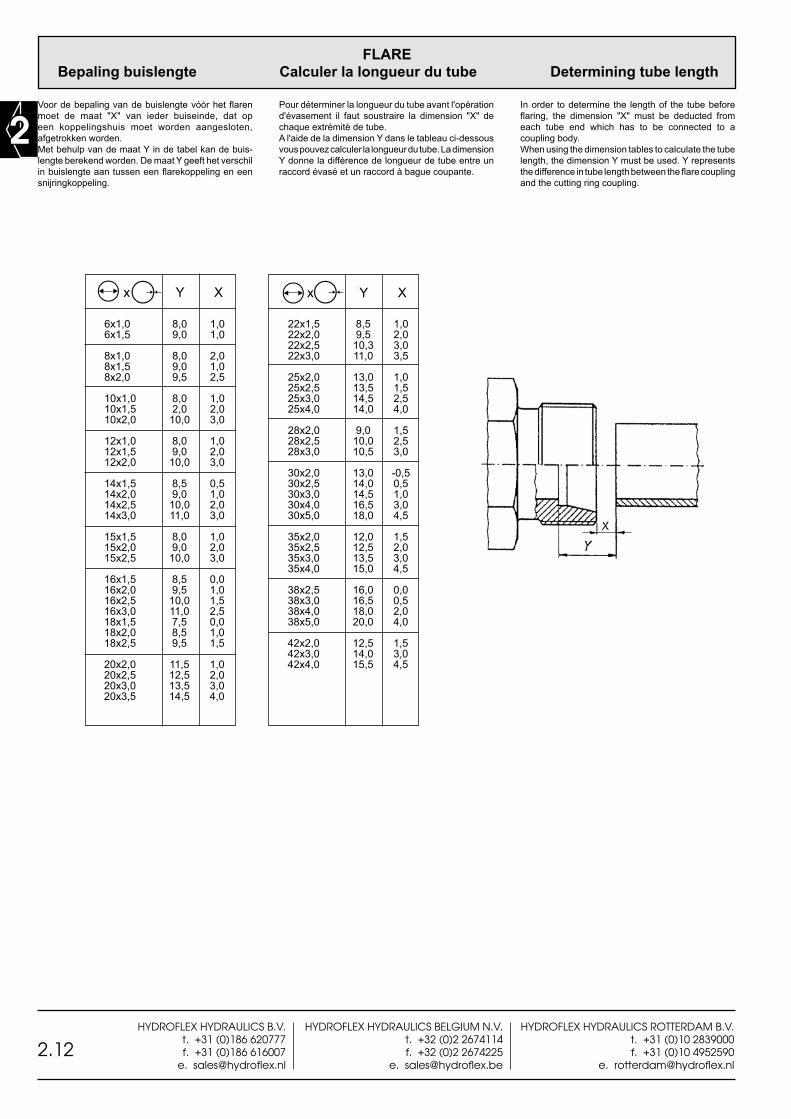
FLARE Bepaling buislengte Calculer la longueur du tube Determining tube length
Voor de bepaling van de buislengte vóór het flaren moet de maat "X" van ieder buiseinde, dat op een koppelingshuis moet worden aangesloten, afgetrokken worden. Met behulp van de maat Y in de tabel kan de buis-lengte berekend worden. De maat Y geeft het verschil in buislengte aan tussen een flarekoppeling en een snijringkoppeling.
In order to determine the length of the tube before flaring, the dimension "X" must be deducted from each tube end which has to be connected to a coupling body. When using the dimension tables to calculate the tube length, the dimension Y must be used. Y represents the difference in tube length between the flare coupling and the cutting ring coupling.
Pour déterminer la longueur du tube avant l'opération d'évasement il faut soustraire la dimension "X" de chaque extrémité de tube. A l'aide de la dimension Y dans le tableau ci-dessous vous pouvez calculer la longueur du tube. La dimension Y donne la différence de longueur de tube entre un raccord évasé et un raccord à bague coupante.
6x1,0 8,0 1,0 6x1,5 9,0 1,0
8x1,0 8,0 2,0 8x1,5 9,0 1,0 8x2,0 9,5 2,5
10x1,0 8,0 1,0 10x1,5 2,0 2,0 10x2,0 10,0 3,0
12x1,0 8,0 1,0 12x1,5 9,0 2,0 12x2,0 10,0 3,0
14x1,5 8,5 0,5 14x2,0 9,0 1,0 14x2,5 10,0 2,0 14x3,0 11,0 3,0
15x1,5 8,0 1,0 15x2,0 9,0 2,0 15x2,5 10,0 3,0
16x1,5 8,5 0,0 16x2,0 9,5 1,0 16x2,5 10,0 1,5 16x3,0 11,0 2,5 18x1,5 7,5 0,0 18x2,0 8,5 1,0 18x2,5 9,5 1,5
20x2,0 11,5 1,0 20x2,5 12,5 2,0 20x3,0 13,5 3,0 20x3,5 14,5 4,0
x Y X x Y X
22x1,5 8,5 1,0 22x2,0 9,5 2,0 22x2,5 10,3 3,0 22x3,0 11,0 3,5
25x2,0 13,0 1,0 25x2,5 13,5 1,5 25x3,0 14,5 2,5 25x4,0 14,0 4,0 28x2,0 9,0 1,5 28x2,5 10,0 2,5 28x3,0 10,5 3,0
30x2,0 13,0 -0,5 30x2,5 14,0 0,5 30x3,0 14,5 1,0 30x4,0 16,5 3,0 30x5,0 18,0 4,5
35x2,0 12,0 1,5 35x2,5 12,5 2,0 35x3,0 13,5 3,0 35x4,0 15,0 4,5
38x2,5 16,0 0,0 38x3,0 16,5 0,5 38x4,0 18,0 2,0 38x5,0 20,0 4,0
42x2,0 12,5 1,5 42x3,0 14,0 3,0 42x4,0 15,5 4,5