Leben im Bad Living bathrooms -...
32
Bedienungs- und Montageanleitung für Badmöbel mit Stromführung Operating and mounting instructions for bathroom furniture with electrical supply Notice d'utilisation et de montage pour meubles de salle de bains avec alimentation électrique Gebruikshandleiding en montageaanwijzing voor badmeubilair met stroomverzorging Istruizioni d'uso e di montaggio per mobili per il bagno elettrificati Manual de instrucciones e instrucciones de montaje para muebles para el bagno con suministro eléctrico Leben im Bad Living bathrooms
Transcript of Leben im Bad Living bathrooms -...
Bedienungs- und Montageanleitung für Badmöbel mit Stromführung
Operating and mounting instructions for bathroom furniture with electrical supply
Notice d'utilisation et de montage pour meubles de salle de bains avec alimentation
électrique
Gebruikshandleiding en montageaanwijzing voor badmeubilair met stroomverzorging
Istruizioni d'uso e di montaggio per mobili per il bagno elettrificati
Manual de instrucciones e instrucciones de montaje para muebles para el bagno con
suministro eléctrico
Leben im BadLiving bathrooms
2 MAL_52288/06.11.6
MAL_52288/06.11.6 3
Deutsch
Technische Informationen
Kurzbeschreibung ........................ 4
Schaltung der Produkte ............... 10
Inbetriebnahme
Messemodus ............................... 16
Einstellen der Helligkeit ............. 17
Anforderungen an Möbel
mit Elektrifizierung oder
Leuchten ............................... 18/19
English
Technical information
Brief description ........................... 5
Product activation ........................ 11
Getting Started
Display mode .............................. 16
Setting the brightness ................ 17
Requests for furniture with
electricification or lamps ...... 20/21
Français
Informations techniques
Généralités ................................... 6
Dispositif de commande ............. 12
Mise en service
Module expo ............................... 16
Réglage de la luminosité ............ 17
Demandes en meubles avec
électrification ou éclairage ... 22/23
Nederlands
Technische informatie
Korte beschrijving ........................ 7
Schakelen van de producten ...... 13
In gebruik nemen
Demomodus ............................... 16
Instellen van de helderheid ........ 17
Eisen welke aan meubelen
gesteld worden met elektra
of verlichting......................... 24/25
Italiano
Informazioni tecniche
Breve descrizione ......................... 8
Collegamento dei prodotti .......... 14
Messa in funzione
Modalità sala mostra .................. 16
Regolazione della luminosità ..... 17
Requisiti di mobili
elettrificati o lampade .......... 26/27
Español
Informaciones técnicas
Descripción breve ......................... 9
Conexión de los productos ............ 15
Puesta en servicio
Modo feria/exposición ................ 16
Ajuste de la intensidad ............... 17
Requisitos para instalaciones
de muebles con toma
de corriente eléctrica ........... 28/29
Index

Netzanschluss
L = braun = gelb/grün N = blau
HINWEIS
Der Netzanschluss von Möbeln mit Beleuchtung darf nur von einem Fachmann unter Berücksichtigung der des Landes ent-
sprechenden Norm erfolgen. Hierbei darf der Netzanschluss nur in einer Anschlussdose mit mindestens gleicher Schutzart
der Leuchte vorgenommen werden.
WICHTIG!
Der Leiter mit der grün-gelben Isolation muss an den Schutzleiter (Klemme mit der Bezeichnung oder ) angeschlos-
sen werden!
AC 230 V / 50 HZ
Elektrisches Anschlussfeld
Europa EN 60598-1,2Deutschland VDE 100, Teil 701Österreich ÖVE-EN 1, Teil 4, § 49Schweiz NIN 100Frankreich NF.C. 15-100, section 7-701Luxemburg EVU/VDE 100, Teil 701Großbritannien BS 7671 Niederlande NEN 1010, 727.1+2Belgien R.G.I.E., Art. 86.10Italien CEI 64-8/7 sez. 701
Bevor Sie beginnenVielen Dank, dass Sie sich für unser Produkt entschieden haben. Damit Sie an Ihren DURAVIT-Badmöbeln lange Freude
haben, finden Sie nachstehend die nötigen Hinweise. Nehmen Sie sich einige Minuten Zeit, bevor Sie mit der Montage und
Benutzung Ihrer DURAVIT-Badmöbel beginnen. Nur so können Unfälle und Beschädigungen am Produkt vermieden werden.
Über das ProduktDie DURAVIT-Badmöbel entsprechen den derzeit gültigen Normen und Richtlinien und sind für den Einsatz in Bädern konzi-
piert. Eine direkte Benetzung mit Wasser z.B. beim Duschen ist zu vermeiden.
Zu Ihrer SicherheitDurch Berührung von spannungsführenden Teilen kann es zu Verletzungen bis zum Tode kommen.
– Die Montage hat gemäß der vorliegenden Anleitung und in Übereinstimmung mit allen nationalen, europaweiten und
internationalen Richtlinien und Normen zu erfolgen.
– Der elektronische Anschluss muss über einen GFI-Sicherungsautomaten erfolgen (gilt nur für Feuchträume z.B. Badezimmer
oder sonstige speziell ausgewiesene Räumlichkeiten).
– Bei allen Arbeiten an elektrischen Komponenten ist zuvor der entsprechende Sicherungsautomat auszuschalten.
Vergewissern Sie sich stets, dass tatsächlich keine Spannung mehr anliegt. Sorgen Sie dafür, dass die Stromzufuhr nicht
versehentlich zugeschaltet werden kann.
Duravit behält sich das Recht auf Produktänderungen infolge technischer Verbesserungen vor.
I L N
II
L N
III
Leuchten der Schutzklasse Anschlussleitung/Anschlussbild
H03VV H2-F/H03VV-F, min. 1,5 qmm
H03VV-F, min. 0,75 qmm
AC 12 V
4 MAL_52288/06.11.6
Deutsch
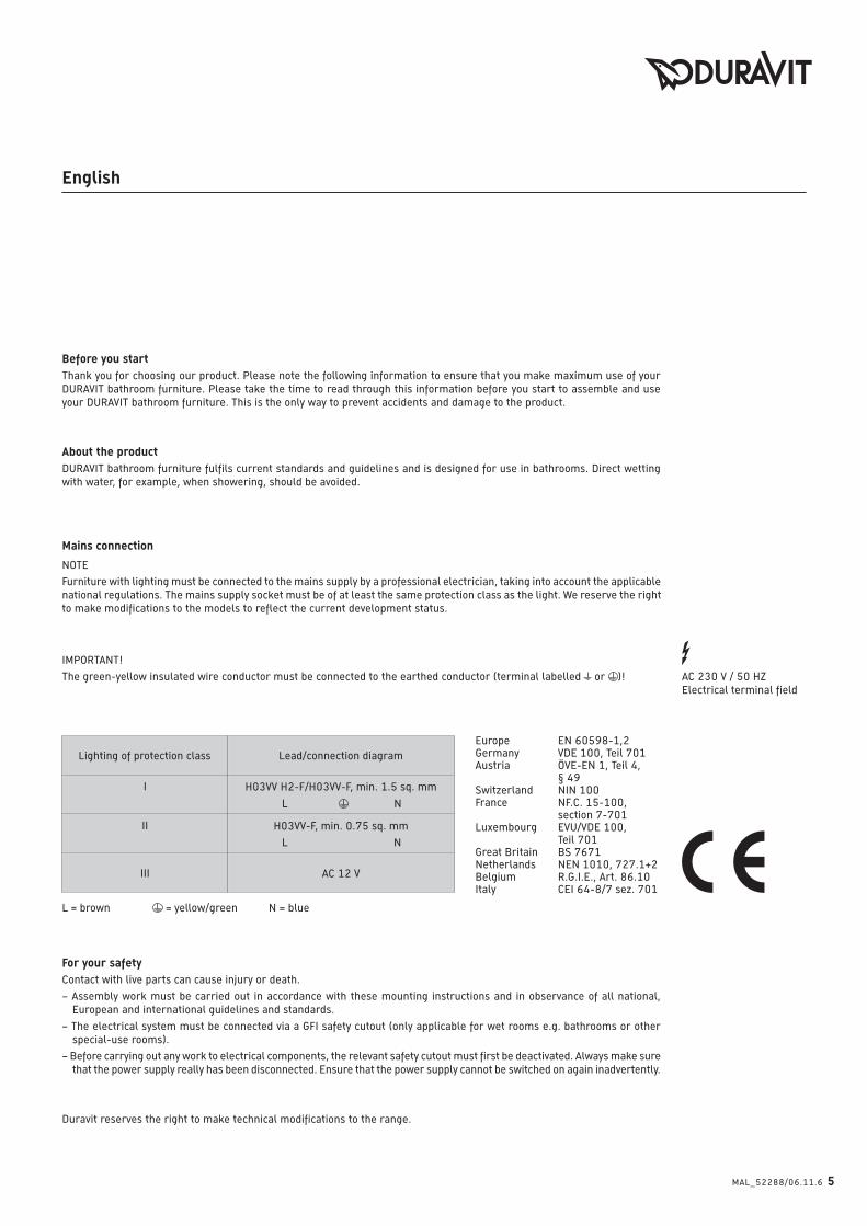
Mains connection
NOTE
Furniture with lighting must be connected to the mains supply by a professional electrician, taking into account the applicable
national regulations. The mains supply socket must be of at least the same protection class as the light. We reserve the right
to make modifications to the models to reflect the current development status.
IMPORTANT!
The green-yellow insulated wire conductor must be connected to the earthed conductor (terminal labelled or )! AC 230 V / 50 HZ
Electrical terminal field
Europe EN 60598-1,2Germany VDE 100, Teil 701Austria ÖVE-EN 1, Teil 4, § 49Switzerland NIN 100France NF.C. 15-100, section 7-701Luxembourg EVU/VDE 100, Teil 701Great Britain BS 7671 Netherlands NEN 1010, 727.1+2Belgium R.G.I.E., Art. 86.10Italy CEI 64-8/7 sez. 701
Before you startThank you for choosing our product. Please note the following information to ensure that you make maximum use of your
DURAVIT bathroom furniture. Please take the time to read through this information before you start to assemble and use
your DURAVIT bathroom furniture. This is the only way to prevent accidents and damage to the product.
About the productDURAVIT bathroom furniture fulfils current standards and guidelines and is designed for use in bathrooms. Direct wetting
with water, for example, when showering, should be avoided.
For your safetyContact with live parts can cause injury or death.
– Assembly work must be carried out in accordance with these mounting instructions and in observance of all national,
European and international guidelines and standards.
– The electrical system must be connected via a GFI safety cutout (only applicable for wet rooms e.g. bathrooms or other
special-use rooms).
– Before carrying out any work to electrical components, the relevant safety cutout must first be deactivated. Always make sure
that the power supply really has been disconnected. Ensure that the power supply cannot be switched on again inadvertently.
Duravit reserves the right to make technical modifications to the range.
L = brown = yellow/green N = blue
I
L N
II
L N
III
Lighting of protection class Lead/connection diagram
H03VV H2-F/H03VV-F, min. 1.5 sq. mm
H03VV-F, min. 0.75 sq. mm
AC 12 V
MAL_52288/06.11.6 5
English
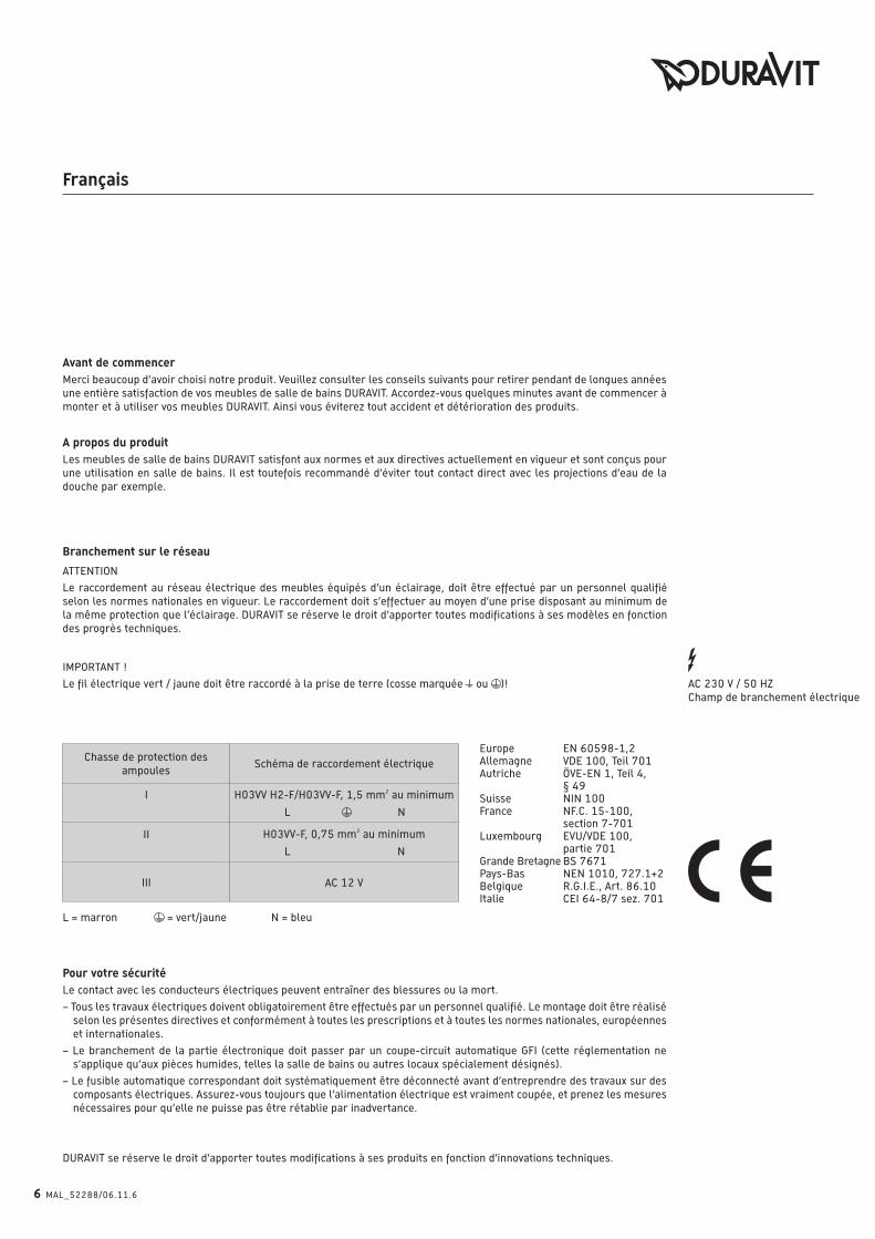
Branchement sur le réseau
L = marron = vert/jaune N = bleu
ATTENTION
Le raccordement au réseau électrique des meubles équipés d’un éclairage, doit être effectué par un personnel qualifié
selon les normes nationales en vigueur. Le raccordement doit s’effectuer au moyen d’une prise disposant au minimum de
la même protection que l’éclairage. DURAVIT se réserve le droit d’apporter toutes modifications à ses modèles en fonction
des progrès techniques.
IMPORTANT !
Le fil électrique vert / jaune doit être raccordé à la prise de terre (cosse marquée ou )! AC 230 V / 50 HZ
Champ de branchement électrique
Europe EN 60598-1,2Allemagne VDE 100, Teil 701Autriche ÖVE-EN 1, Teil 4, § 49Suisse NIN 100France NF.C. 15-100, section 7-701Luxembourg EVU/VDE 100, partie 701Grande Bretagne BS 7671 Pays-Bas NEN 1010, 727.1+2Belgique R.G.I.E., Art. 86.10Italie CEI 64-8/7 sez. 701
Avant de commencerMerci beaucoup d’avoir choisi notre produit. Veuillez consulter les conseils suivants pour retirer pendant de longues années
une entière satisfaction de vos meubles de salle de bains DURAVIT. Accordez-vous quelques minutes avant de commencer à
monter et à utiliser vos meubles DURAVIT. Ainsi vous éviterez tout accident et détérioration des produits.
A propos du produitLes meubles de salle de bains DURAVIT satisfont aux normes et aux directives actuellement en vigueur et sont conçus pour
une utilisation en salle de bains. Il est toutefois recommandé d’éviter tout contact direct avec les projections d’eau de la
douche par exemple.
Pour votre sécuritéLe contact avec les conducteurs électriques peuvent entraîner des blessures ou la mort.
– Tous les travaux électriques doivent obligatoirement être effectués par un personnel qualifié. Le montage doit être réalisé
selon les présentes directives et conformément à toutes les prescriptions et à toutes les normes nationales, européennes
et internationales.
– Le branchement de la partie électronique doit passer par un coupe-circuit automatique GFI (cette réglementation ne
s’applique qu’aux pièces humides, telles la salle de bains ou autres locaux spécialement désignés).
– Le fusible automatique correspondant doit systématiquement être déconnecté avant d’entreprendre des travaux sur des
composants électriques. Assurez-vous toujours que l’alimentation électrique est vraiment coupée, et prenez les mesures
nécessaires pour qu’elle ne puisse pas être rétablie par inadvertance.
DURAVIT se réserve le droit d’apporter toutes modifications à ses produits en fonction d’innovations techniques.
I
L N
II
L N
III
Chasse de protection des
ampoulesSchéma de raccordement électrique
H03VV H2-F/H03VV-F, 1,5 mm2 au minimum
H03VV-F, 0,75 mm2 au minimum
AC 12 V
6 MAL_52288/06.11.6
Français
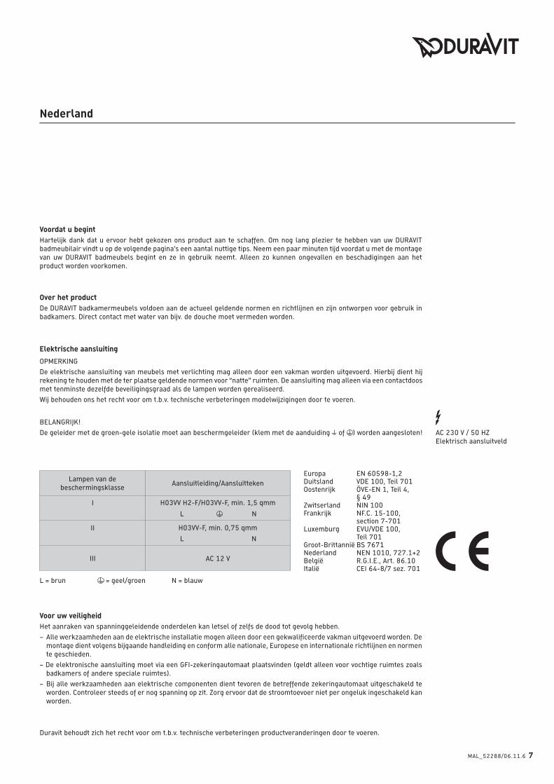
Elektrische aansluiting
L = brun = geel/groen N = blauw
OPMERKING
De elektrische aansluiting van meubels met verlichting mag alleen door een vakman worden uitgevoerd. Hierbij dient hij
rekening te houden met de ter plaatse geldende normen voor “natte” ruimten. De aansluiting mag alleen via een contactdoos
met tenminste dezelfde beveiligingsgraad als de lampen worden gerealiseerd.
Wij behouden ons het recht voor om t.b.v. technische verbeteringen modelwijzigingen door te voeren.
BELANGRIJK!
De geleider met de groen-gele isolatie moet aan beschermgeleider (klem met de aanduiding of ) worden aangesloten! AC 230 V / 50 HZ
Elektrisch aansluitveld
Europa EN 60598-1,2Duitsland VDE 100, Teil 701Oostenrijk ÖVE-EN 1, Teil 4, § 49Zwitserland NIN 100Frankrijk NF.C. 15-100, section 7-701Luxemburg EVU/VDE 100, Teil 701Groot-Brittannië BS 7671 Nederland NEN 1010, 727.1+2België R.G.I.E., Art. 86.10Italië CEI 64-8/7 sez. 701
Voordat u begintHartelijk dank dat u ervoor hebt gekozen ons product aan te schaffen. Om nog lang plezier te hebben van uw DURAVIT
badmeubilair vindt u op de volgende pagina’s een aantal nuttige tips. Neem een paar minuten tijd voordat u met de montage
van uw DURAVIT badmeubels begint en ze in gebruik neemt. Alleen zo kunnen ongevallen en beschadigingen aan het
product worden voorkomen.
Over het productDe DURAVIT badkamermeubels voldoen aan de actueel geldende normen en richtlijnen en zijn ontworpen voor gebruik in
badkamers. Direct contact met water van bijv. de douche moet vermeden worden.
Voor uw veiligheidHet aanraken van spanninggeleidende onderdelen kan letsel of zelfs de dood tot gevolg hebben.
– Alle werkzaamheden aan de elektrische installatie mogen alleen door een gekwalificeerde vakman uitgevoerd worden. De
montage dient volgens bijgaande handleiding en conform alle nationale, Europese en internationale richtlijnen en normen
te geschieden.
– De elektronische aansluiting moet via een GFI-zekeringautomaat plaatsvinden (geldt alleen voor vochtige ruimtes zoals
badkamers of andere speciale ruimtes).
– Bij alle werkzaamheden aan elektrische componenten dient tevoren de betreffende zekeringautomaat uitgeschakeld te
worden. Controleer steeds of er nog spanning op zit. Zorg ervoor dat de stroomtoevoer niet per ongeluk ingeschakeld kan
worden.
Duravit behoudt zich het recht voor om t.b.v. technische verbeteringen productveranderingen door te voeren.
I
L N
II
L N
III
Lampen van de
beschermingsklasseAansluitleiding/Aansluitteken
H03VV H2-F/H03VV-F, min. 1,5 qmm
H03VV-F, min. 0,75 qmm
AC 12 V
MAL_52288/06.11.6 7
Nederland
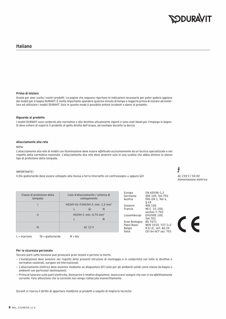
Allacciamento alla rete
L = marrone = giallo/verde N = blu
NOTA
L'allacciamento alla rete di mobili con illuminazione deve essere effettuato esclusivamente da un tecnico specializzato e nel
rispetto della normativa nazionale. L'allacciamento alla rete deve avvenire solo in una scatola che abbia almeno lo stesso
tipo di protezione della lampada.
IMPORTANTE!
Il filo giallo/verde deve essere collegato alla messa a terra (morsetto col contrassegno oppure )! AC 230 V / 50 HZ
Alimentazione elettrica
Europa EN 60598-1,2Germania VDE 100, Teil 701Austria ÖVE-EN 1, Teil 4, § 49Svizzera NIN 100Francia NF.C. 15-100, section 7-701Lussemburgo EVU/VDE 100, Teil 701Gran Bretagna BS 7671 Paesi Bassi NEN 1010, 727.1+2Belgio R.G.I.E., Art. 86.10Italia CEI 64-8/7 sez. 701
Prima di iniziareGrazie per aver scelto i nostri prodotti. Le pagine che seguono riportano le indicazioni necessarie per poter godere appieno
dei mobili per il bagno DURAVIT. È molto importante spendere qualche minuto di tempo e leggerle prima di iniziare ad instal-
lare ed utilizzare i mobili DURAVIT. Solo in questo modo è possibile evitare incidenti e danni al prodotto.
Riguardo al prodottoI mobili DURAVIT sono conformi alle normative e alle direttive attualmente vigenti e sono stati ideati per l‘impiego in bagno.
Si deve evitare di esporre il prodotto al getto diretto dell'acqua, ad esempio durante la doccia.
Per la sicurezza personaleToccare parti sotto tensione può provocare gravi lesioni e persino la morte.
– L'installazione deve avvenire nel rispetto delle presenti istruzioni di montaggio e in conformità con tutte le direttive e
normative nazionali, europee ed internazionali.
– L'allacciamento elettrico deve avvenire mediante un disgiuntore GFI (solo per gli ambienti umidi come stanze da bagno o
ambienti con particolari destinazioni).
– Prima di lavorare sulle parti elettriche, disinserire il relativo disgiuntore. Assicurarsi sempre che non ci sia effettivamente
corrente. Fare attenzione che la corrente non venga riattaccata inavvertitamente.
Duravit si riserva il diritto di apportare modifiche ai prodotti a seguito di migliorie tecniche.
I
L N
II
L N
III
Classe di protezione della
lampada
Cavo d'allacciamento / schema di
collegamento
H03VV H2-F/H03VV-F, min. 1,5 mm2
H03VV-F, min. 0,75 mm2
AC 12 V
8 MAL_52288/06.11.6
Italiano
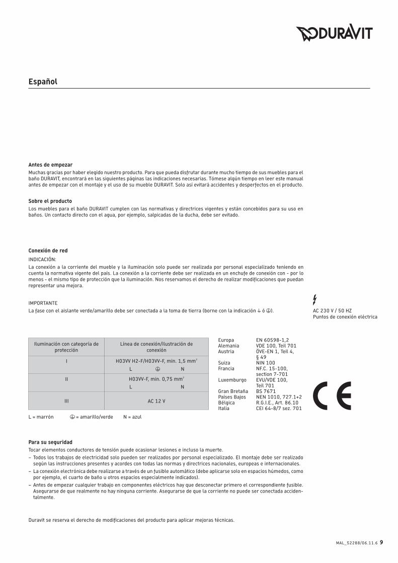
Conexión de red
L = marrón = amarillo/verde N = azul
INDICACIÓN:
La conexión a la corriente del mueble y la iluminación solo puede ser realizada por personal especializado teniendo en
cuenta la normativa vigente del país. La conexión a la corriente debe ser realizada en un enchufe de conexión con - por lo
menos - el mismo tipo de protección que la iluminación. Nos reservamos el derecho de realizar modificaciones que puedan
representar una mejora.
IMPORTANTE
La fase con el aislante verde/amarillo debe ser conectada a la toma de tierra (borne con la indicación ó ). AC 230 V / 50 HZ
Puntos de conexión eléctrica
Europa EN 60598-1,2Alemania VDE 100, Teil 701Austria ÖVE-EN 1, Teil 4, § 49Suiza NIN 100Francia NF.C. 15-100, section 7-701Luxemburgo EVU/VDE 100, Teil 701Gran Bretaña BS 7671 Países Bajos NEN 1010, 727.1+2Bélgica R.G.I.E., Art. 86.10Italia CEI 64-8/7 sez. 701
Antes de empezarMuchas gracias por haber elegido nuestro producto. Para que pueda disfrutar durante mucho tiempo de sus muebles para el
baño DURAVIT, encontrará en las siguientes páginas las indicaciones necesarias. Tómese algún tiempo en leer este manual
antes de empezar con el montaje y el uso de su mueble DURAVIT. Solo así evitará accidentes y desperfectos en el producto.
Sobre el productoLos muebles para el baño DURAVIT cumplen con las normativas y directrices vigentes y están concebidos para su uso en
baños. Un contacto directo con el agua, por ejemplo, salpicadas de la ducha, debe ser evitado.
Para su seguridadTocar elementos conductores de tensión puede ocasionar lesiones e incluso la muerte.
– Todos los trabajos de electricidad solo pueden ser realizados por personal especializado. El montaje debe ser realizado
según las instrucciones presentes y acordes con todas las normas y directrices nacionales, europeas e internacionales.
– La conexión electrónica debe realizarse a través de un fusible automático (debe aplicarse solo en espacios húmedos, como
por ejemplo, el cuarto de baño u otros espacios especialmente indicados).
– Antes de empezar cualquier trabajo en componentes eléctricos hay que desconectar primero el correspondiente fusible.
Asegurarse de que realmente no hay ninguna corriente. Asegurarse de que la corriente no puede ser conectada acciden-
talmente.
Duravit se reserva el derecho de modificaciones del producto para aplicar mejoras técnicas.
I
L N
II
L N
III
Iluminación con categoría de
protección
Línea de conexión/ilustración de
conexión
H03VV H2-F/H03VV-F, min. 1,5 mm2
H03VV-F, min. 0,75 mm2
AC 12 V
MAL_52288/06.11.6 9
Español

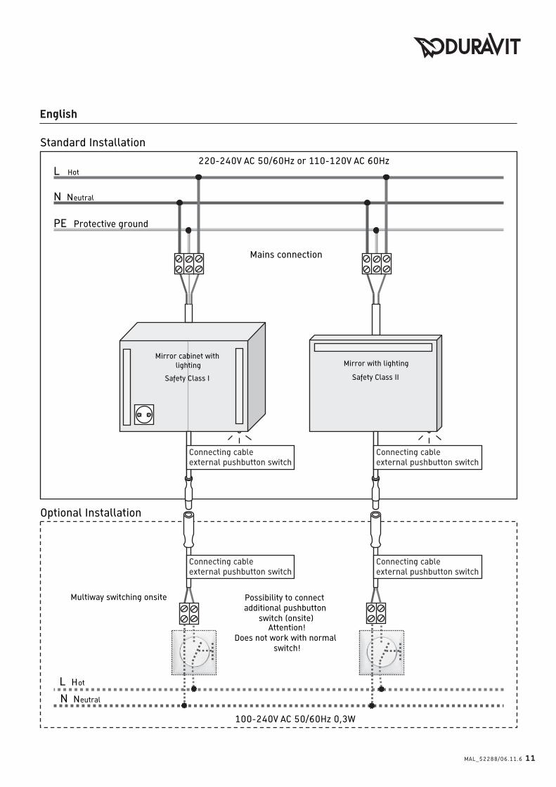
L Phase
N Nulleiter
220-240V AC 50/60Hz oder 110-120V AC 60Hz
PE Schutzleiter
Netzanschluss
Anschlussmöglichkeit
für Taster (bauseits)
Achtung!Nicht mit Schalter möglich!
100-240V AC 50/60Hz 0,3W
Standard Installation
Optionale Installation
Spiegel mit Beleuchtung
Schutzklasse II
Spiegelschrank mit
Beleuchtung
Schutzklasse I
L Phase
N Nulleiter
Wechselschaltung bauseits
Anschlusskabel
externer Taster
Anschlusskabel
externer Taster
Anschlusskabel
externer Taster
Anschlusskabel
externer Taster
10 MAL_52288/06.11.6
Deutsch
Connecting cable
external pushbutton switch
L Hot
N Neutral
220-240V AC 50/60Hz or 110-120V AC 60Hz
PE Protective ground
Mains connection
Possibility to connect
additional pushbutton
switch (onsite) Attention!
Does not work with normal
switch!
100-240V AC 50/60Hz 0,3W
Standard Installation
Optional Installation
Mirror with lighting
Safety Class II
Mirror cabinet with
lighting
Safety Class I
L Hot
N Neutral
Multiway switching onsite
Connecting cable
external pushbutton switch
Connecting cable
external pushbutton switch
Connecting cable
external pushbutton switch
MAL_52288/06.11.6 11
English
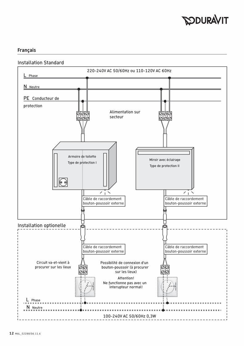
Câble de raccordement
bouton-poussoir externe
L Phase
N Neutre
220-240V AC 50/60Hz ou 110-120V AC 60Hz
PE Conducteur de
protection
Alimentation sur
secteur
Possibilité de connexion d‘un
bouton-poussoir (à procurer
sur les lieux)
Attention!
Ne functionne pas avec un interupteur normal!
100-240V AC 50/60Hz 0,3W
Installation Standard
Installation optionelle
Miroir avec éclairage
Type de protection II
Armoire de toilette
Type de protection I
L Phase
N Neutre
Circuit va-et-vient à
procurer sur les lieux
Câble de raccordement
bouton-poussoir externe
Câble de raccordement
bouton-poussoir externe
Câble de raccordement
bouton-poussoir externe
12 MAL_52288/06.11.6
Français
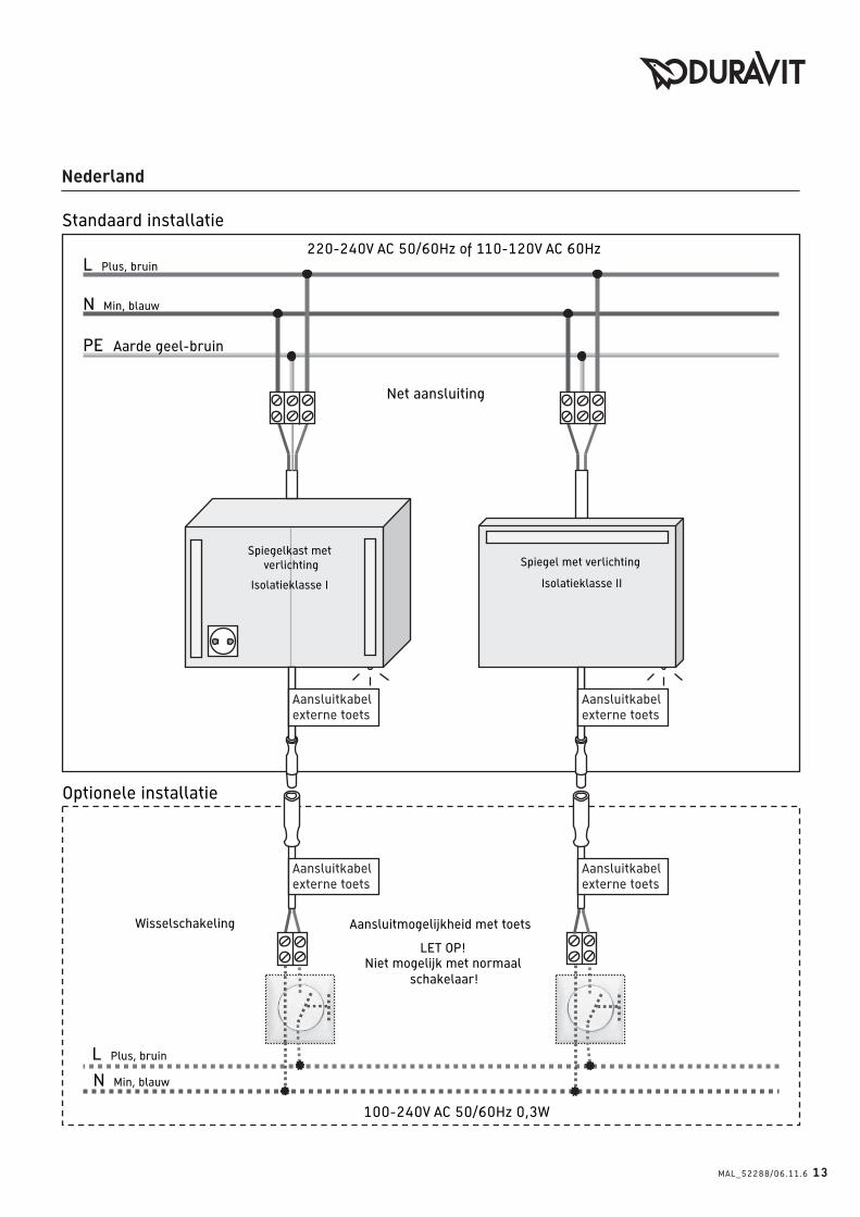
Aansluitkabel
externe toets
L Plus, bruin
N Min, blauw
220-240V AC 50/60Hz of 110-120V AC 60Hz
PE Aarde geel-bruin
Net aansluiting
Aansluitmogelijkheid met toets
LET OP!Niet mogelijk met normaal
schakelaar!
100-240V AC 50/60Hz 0,3W
Standaard installatie
Optionele installatie
Spiegel met verlichting
Isolatieklasse II
Spiegelkast met
verlichting
Isolatieklasse I
L Plus, bruin
N Min, blauw
Wisselschakeling
Aansluitkabel
externe toets
Aansluitkabel
externe toets
Aansluitkabel
externe toets
MAL_52288/06.11.6 13
Nederland
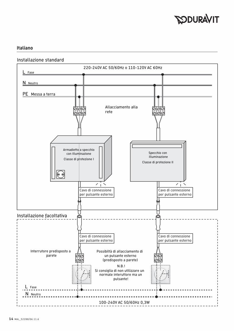
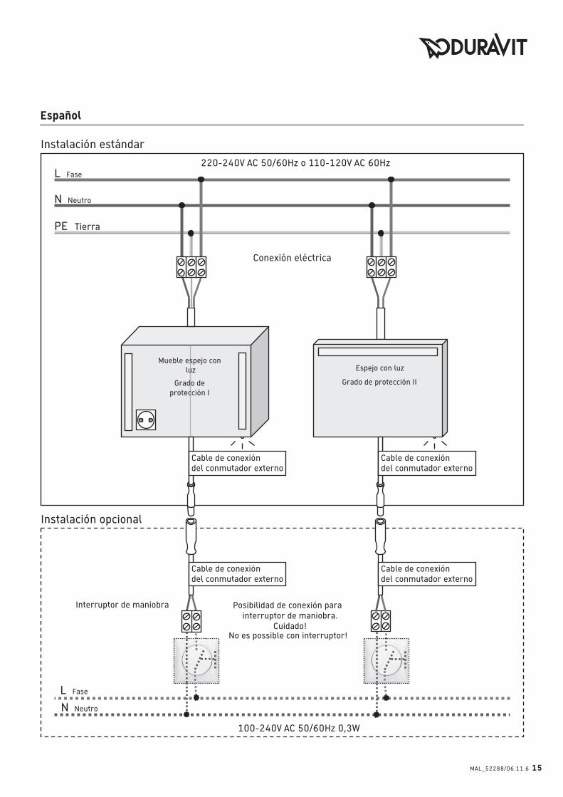
L Fase
N Neutro
220-240V AC 50/60Hz o 110-120V AC 60Hz
PE Messa a terra
Allacciamento alla
rete
Possibiltà di allacciamento di
un pulsante esterno
(predisposto a parete)
N.B.!
Si consiglia di non utilizzare un normale interuttore ma un
pulsante!
100-240V AC 50/60Hz 0,3W
Installazione standard
Installazione facoltativa
Specchio con
illuminazione
Classe di protezione II
Armadietto a specchio
con illuminazione
Classe di protezione I
L Fase
N Neutro
Interrutore predisposto a
parete
Cavo di connessione
per pulsante esterno
Cavo di connessione
per pulsante esterno
Cavo di connessione
per pulsante esterno
Cavo di connessione
per pulsante esterno
14 MAL_52288/06.11.6
Italiano
L Fase
N Neutro
220-240V AC 50/60Hz o 110-120V AC 60Hz
PE Tierra
Conexión eléctrica
Posibilidad de conexión para
interruptor de maniobra.
Cuidado!No es possible con interruptor!
100-240V AC 50/60Hz 0,3W
Instalación estándar
Instalación opcional
Espejo con luz
Grado de protección II
Mueble espejo con
luz
Grado de
protección I
L Fase
N Neutro
Interruptor de maniobra
Cable de conexión
del conmutador externo
Cable de conexión
del conmutador externo
Cable de conexión
del conmutador externo
Cable de conexión
del conmutador externo
MAL_52288/06.11.6 15
Español
MESSEMODUS
Achtung: Die Steuerung enthält ei-
nen Messemodus.
Messemodus: Licht schaltet sich
nach dem Ausschalten automatisch
wieder ein.
Aktivierung Messemodus: Perma-
nente Betätigung (> 65 Sekunden)
von Touch-LED / Infrarotschalter.
Deaktivierung Messemodus: Perma-
nente Betätigung (> 65 Sekunden)
von Touch-LED / Infrarotschalter.
Während der Montag kann der Mes-
semodus durch unabsichtliche
Dauerbetätigung (>65 Sek.) von
Touch-LED / Infrarotschalter der
Messemodus ausgelöst werden.
DISPLAY MODEAttention: The control unit includes
a display mode.
Display Mode: Light turns back on
automatically after being switched
off.
Activation of Display Mode: Press
and hold (> 65 seconds) Touch-LED
/ Infrared Switch
Deactivation of Display Mode: Press
and hold (> 65 seconds) Touch-LED
/ Infrared Switch
During installation it is possible to
activate the Display Mode acciden-
tally by pressing and holding (> 65
seconds) the Touch-LED / Infrared
Switch.
MODULE EXPOAttention : le boîtier électronique
possède un module expo.
Module expo : après mise sous ten-
sion, la lumière se rallume automa-
tiquement.
Activation module expo : implulsion
permanente de + de 65 sec. du
touch-LED ou du capteur sensitif.
Désactivation module expo : implul-
sion permanente de + de 65 sec. du
touch-LED ou du capteur sensitif.
Pendant le montage, le module
expo peut accidentellement être
activé si implulsion de + de 65 sec.
du touch-LED ou du capteur sensitif
est maintenu.
DEMOMODUSOPGELET: De sturing bevat een de-
momodus.
Demomodus: Licht gaat na het uit-
schakelen automatisch weer aan.
Activering demomodus: Constante
bediening (> 65 seconden) van
Touch-LED / infraroodschakelaar.
Desactivering demomodus: Con-
stante bediening (> 65 seconden)
van Touch-LED / infraroodschake-
laar.
Bij de montage kan de demomodus
door onopzettelijke constante be-
diening (>65 sec.) van Touch-LED /
infraroodschakelaar ingeschakeld
worden.
MODALITÀ SALA MOSTRAAttenzione! L’unità di comando com-
prende una modalità sala mostra.
Modalità sala mostra: la luce si ri-
accende automaticamente dopo es-
sere stata spenta.
Attivazione della modalità sala mo-
stra: tenere premuto l’interruttore
a infrarossi/Touch-LED per più di
65 secondi.
Disattivazione della modalità sala
mostra: tenere premuto l’interrut-
tore a infrarossi/Touch-LED per più
di 65 secondi.
Durante l’installazione prestare at-
tenzione a non attivare accidental-
mente la modalità sala mostra te-
nendo premuto l’interruttore a
infrarossi / Touch-LED per più di 65
secondi.
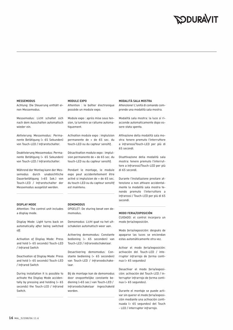
MODO FERIA/EXPOSICIÓNCUIDADO: el control incorpora un
modo feria/exposición.
Modo feria/exposición: después de
apagarse las luces se enciendan
estas automáticamente otra vez.
Activar el modo feria/exposición:
activación del Touch-LED / inte-
rruptor infrarrojo de forma conti-
nua (> 65 segundos)
Desactivar el modo feria/exposi-
ción: activación del Touch-LED / in-
terruptor infrarrojo de forma conti-
nua (> 65 segundos).
Durante el montaje se puede acti-
var sin querer el modo feria/exposi-
ción mediante una activación conti-
nuada (> 65 segundos) del Touch
- LED / interruptor infrarrojo.
16 MAL_52288/06.11.6
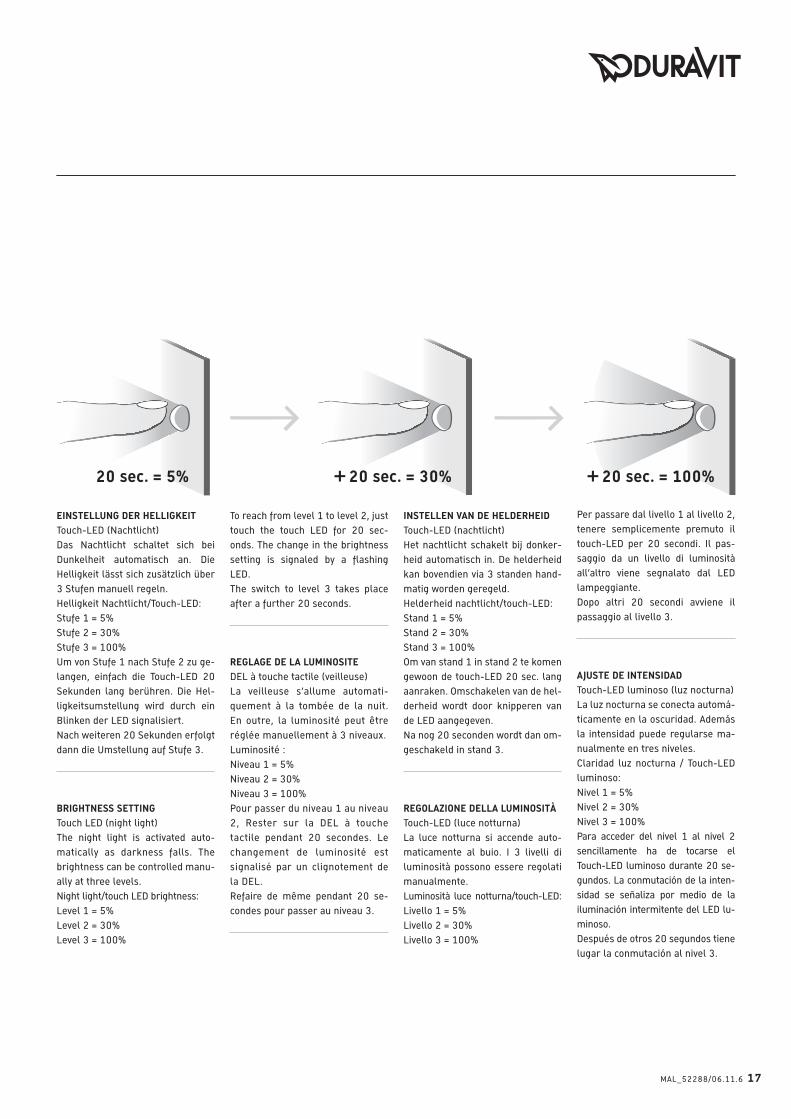
20 sec. = 5% 20 sec. = 30%+ 20 sec. = 100%+ EINSTELLUNG DER HELLIGKEITTouch-LED (Nachtlicht)
Das Nachtlicht schaltet sich bei
Dunkelheit automatisch an. Die
Helligkeit lässt sich zusätzlich über
3 Stufen manuell regeln.
Helligkeit Nachtlicht/Touch-LED:
Stufe 1 = 5%
Stufe 2 = 30%
Stufe 3 = 100%
Um von Stufe 1 nach Stufe 2 zu ge-
langen, einfach die Touch-LED 20
Sekunden lang berühren. Die Hel-
ligkeitsumstellung wird durch ein
Blinken der LED signalisiert.
Nach weiteren 20 Sekunden erfolgt
dann die Umstellung auf Stufe 3.
BRIGHTNESS SETTINGTouch LED (night light)
The night light is activated auto-
matically as darkness falls. The
brightness can be controlled manu-
ally at three levels.
Night light/touch LED brightness:
Level 1 = 5%
Level 2 = 30%
Level 3 = 100%
To reach from level 1 to level 2, just
touch the touch LED for 20 sec-
onds. The change in the brightness
setting is signaled by a flashing
LED.
The switch to level 3 takes place
after a further 20 seconds.
REGLAGE DE LA LUMINOSITEDEL à touche tactile (veilleuse)
La veilleuse s’allume automati-
quement à la tombée de la nuit.
En outre, la luminosité peut être
réglée manuellement à 3 niveaux.
Luminosité :
Niveau 1 = 5%
Niveau 2 = 30%
Niveau 3 = 100%
Pour passer du niveau 1 au niveau
2, Rester sur la DEL à touche
tactile pendant 20 secondes. Le
changement de luminosité est
signalisé par un clignotement de
la DEL.
Refaire de même pendant 20 se-
condes pour passer au niveau 3.
INSTELLEN VAN DE HELDERHEIDTouch-LED (nachtlicht)
Het nachtlicht schakelt bij donker-
heid automatisch in. De helderheid
kan bovendien via 3 standen hand-
matig worden geregeld.
Helderheid nachtlicht/touch-LED:
Stand 1 = 5%
Stand 2 = 30%
Stand 3 = 100%
Om van stand 1 in stand 2 te komen
gewoon de touch-LED 20 sec. lang
aanraken. Omschakelen van de hel-
derheid wordt door knipperen van
de LED aangegeven.
Na nog 20 seconden wordt dan om-
geschakeld in stand 3.
REGOLAZIONE DELLA LUMINOSITÀTouch-LED (luce notturna)
La luce notturna si accende auto-
maticamente al buio. I 3 livelli di
luminosità possono essere regolati
manualmente.
Luminosità luce notturna/touch-LED:
Livello 1 = 5%
Livello 2 = 30%
Livello 3 = 100%
Per passare dal livello 1 al livello 2,
tenere semplicemente premuto il
touch-LED per 20 secondi. Il pas-
saggio da un livello di luminosità
all’altro viene segnalato dal LED
lampeggiante.
Dopo altri 20 secondi avviene il
passaggio al livello 3.
AJUSTE DE INTENSIDADTouch-LED luminoso (luz nocturna)
La luz nocturna se conecta automá-
ticamente en la oscuridad. Además
la intensidad puede regularse ma-
nualmente en tres niveles.
Claridad luz nocturna / Touch-LED
luminoso:
Nivel 1 = 5%
Nivel 2 = 30%
Nivel 3 = 100%
Para acceder del nivel 1 al nivel 2
sencillamente ha de tocarse el
Touch-LED luminoso durante 20 se-
gundos. La conmutación de la inten-
sidad se señaliza por medio de la
iluminación intermitente del LED lu-
minoso.
Después de otros 20 segundos tiene
lugar la conmutación al nivel 3.
MAL_52288/06.11.6 17

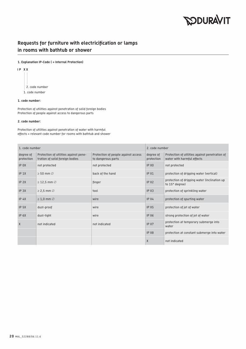
1. Erläuterung IP-Code ( = Internal Protection)
2. Kennziffer
1. Kennziffer
1. Kennziffer:
Schutz des Betriebsmittels gegen Eindringen von festen Fremdkörpern,
Schutz von Personen gegen Zugang zu gefährlichen Teilen
2. Kennziffer:
Schutz des Betriebsmittels gegen das Eindringen von Wasser mit schädlichen
Wirkungen = relevante Kennziffer für Räume mit Badewanne oder Dusche
1. Kennziffer 2. Kennziffer
SchutzgradSchutz des Betriebsmittels gegen das
Eindringen von festen Fremdkörpern
Schutz von Personen gegen Zugang
zu gefährlichen TeilenSchutzgrad
Schutz des Betriebsmittels gegen das Ein-
dringen von Wasser mit schädlicher Wirkung
IP 0X nicht geschützt nicht geschützt IP X0 nicht geschützt
IP 1X ≥ 50 mm Ø Handrücken IP X1 Tropfwasserschutz (senkrecht)
IP 2X ≥ 12,5 mm Ø Finger IP X2 Tropfwasserschutz (bis 15°C Neigung)
IP 3X ≥ 2,5 mm Ø Werkzeug IP X3 Sprühwasserschutz
IP 4X ≥ 1,0 mm Ø Draht IP X4 Spritzwasserschutz
IP 5X staubgeschützt Draht IP X5 Strahlwasserschutz
IP 6X staubdicht Draht IP X6 starker Strahlwasserschutz
X nicht angegeben nicht angegeben IP X7Schutz bei zeitweiligem Untertauchen in
Wasser
IP X8Schutz bei dauerndem Untertauchen in
Wasser
X nicht angegeben
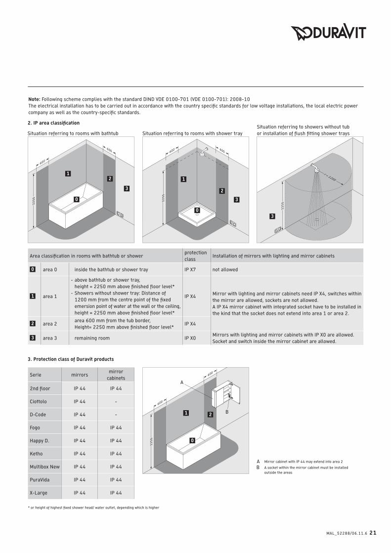
Anforderungen an Möbel mit Elektrifizierung oder Leuchten in Räumen mit Badewanne oder Dusche
18 MAL_52288/06.11.6
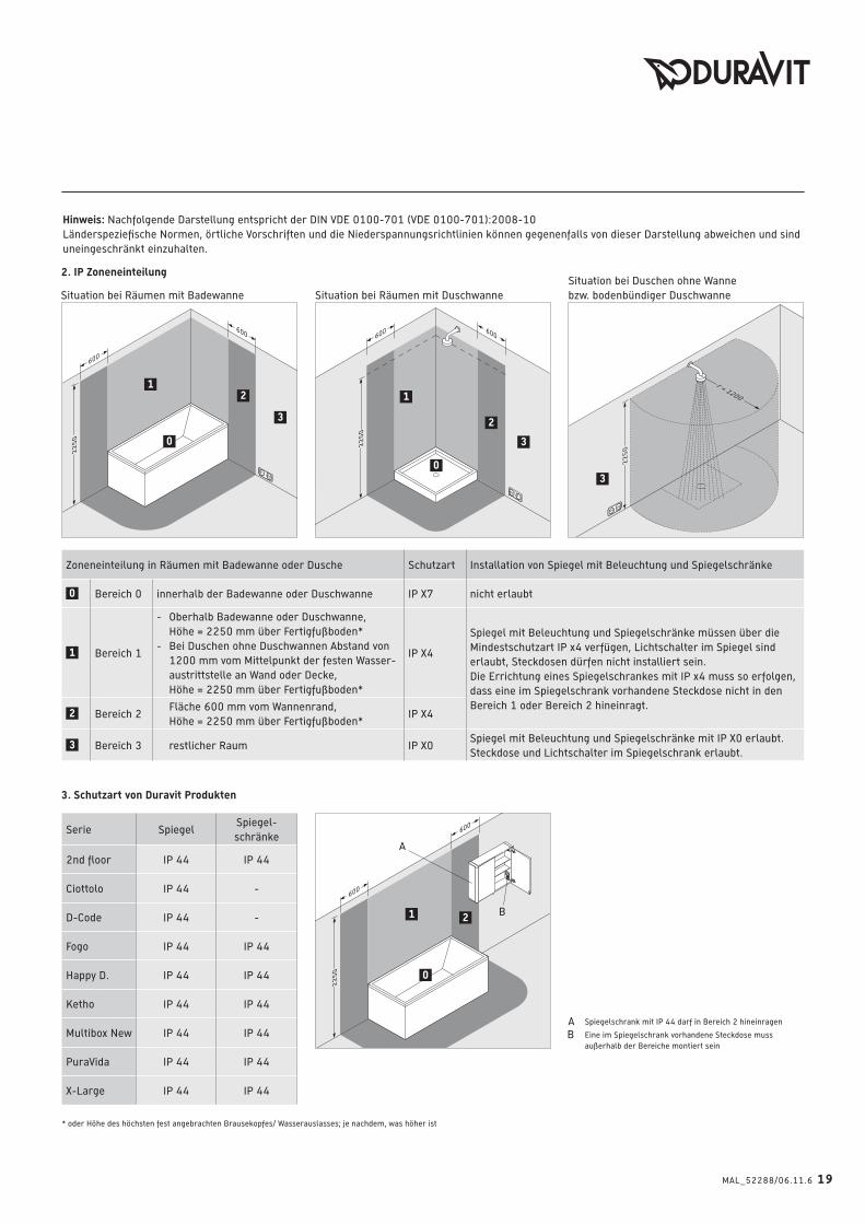
1
600
600
22
50 0
1 2
600
600
22
50 0
12
3
r = 1200
22
50
3
600 600
22
50
0
1
2
3
Hinweis: Nachfolgende Darstellung entspricht der DIN VDE 0100-701 (VDE 0100-701):2008-10
Länderspeziefische Normen, örtliche Vorschriften und die Niederspannungsrichtlinien können gegenenfalls von dieser Darstellung abweichen und sind
uneingeschränkt einzuhalten.
* oder Höhe des höchsten fest angebrachten Brausekopfes/ Wasserauslasses; je nachdem, was höher ist
3. Schutzart von Duravit Produkten
Spiegelschrank mit IP 44 darf in Bereich 2 hineinragen
Eine im Spiegelschrank vorhandene Steckdose muss
außerhalb der Bereiche montiert sein
Zoneneinteilung in Räumen mit Badewanne oder Dusche Schutzart Installation von Spiegel mit Beleuchtung und Spiegelschränke
0 Bereich 0 innerhalb der Badewanne oder Duschwanne IP X7 nicht erlaubt
1 Bereich 1
- Oberhalb Badewanne oder Duschwanne,
Höhe = 2250 mm über Fertigfußboden*
- Bei Duschen ohne Duschwannen Abstand von
1200 mm vom Mittelpunkt der festen Wasser-
austrittstelle an Wand oder Decke,
Höhe = 2250 mm über Fertigfußboden*
IP X4
Spiegel mit Beleuchtung und Spiegelschränke müssen über die
Mindestschutzart IP x4 verfügen, Lichtschalter im Spiegel sind
erlaubt, Steckdosen dürfen nicht installiert sein.
Die Errichtung eines Spiegelschrankes mit IP x4 muss so erfolgen,
dass eine im Spiegelschrank vorhandene Steckdose nicht in den
Bereich 1 oder Bereich 2 hineinragt.2 Bereich 2
Fläche 600 mm vom Wannenrand,
Höhe = 2250 mm über Fertigfußboden*IP X4
3 Bereich 3 restlicher Raum IP X0Spiegel mit Beleuchtung und Spiegelschränke mit IP X0 erlaubt.
Steckdose und Lichtschalter im Spiegelschrank erlaubt.
2. IP Zoneneinteilung
Situation bei Räumen mit Badewanne Situation bei Räumen mit Duschwanne
Situation bei Duschen ohne Wanne
bzw. bodenbündiger Duschwanne
Serie SpiegelSpiegel-
schränke
2nd floor IP 44 IP 44
Ciottolo IP 44 -
D-Code IP 44 -
Fogo IP 44 IP 44
Happy D. IP 44 IP 44
Ketho IP 44 IP 44
Multibox New IP 44 IP 44
PuraVida IP 44 IP 44
X-Large IP 44 IP 44
MAL_52288/06.11.6 19
1. Explanation IP-Code ( = Internal Protection)
2. code number
1. code number
1. code number:
Protection of utilities against penetration of solid foreign bodies
Protection of people against access to dangerous parts
2. code number:
Protection of utilities against penetration of water with harmful
effects = relevant code number for rooms with bathtub and shower
20 MAL_52288/06.11.6
1. code number 2. code number
degree of
protection
Protection of utilities against pene-
tration of solid foreign bodies
Protection of people against access
to dangerous parts
degree of
protection
Protection of utilities against penetration of
water with harmful effects
IP 0X not protected not protected IP X0 not protected
IP 1X ≥ 50 mm Ø back of the hand IP X1 protection of dripping water (vertical)
IP 2X ≥ 12,5 mm Ø finger IP X2protection of dripping water (inclination up
to 15° degree)
IP 3X ≥ 2,5 mm Ø tool IP X3 protection of sprinkling water
IP 4X ≥ 1,0 mm Ø wire IP X4 protection of spurting water
IP 5X dust-proof wire IP X5 protection of jet of water
IP 6X dust-tight wire IP X6 strong protection of jet of water
X not indicated not indicated IP X7protection at temporary submerge into
water
IP X8 protection at constant submerge into water
X not indicated
Requests for furniture with electricification or lamps in rooms with bathtub or shower
1
600
600
22
50 0
1 2
600
600
22
50 0
12
3
r = 1200
22
50
3
600 600
22
50
0
1
2
3
MAL_52288/06.11.6 21
3. Protection class of Duravit products
Serie mirrorsmirror
cabinets
2nd floor IP 44 IP 44
Ciottolo IP 44 -
D-Code IP 44 -
Fogo IP 44 IP 44
Happy D. IP 44 IP 44
Ketho IP 44 IP 44
Multibox New IP 44 IP 44
PuraVida IP 44 IP 44
X-Large IP 44 IP 44
Mirror cabinet with IP 44 may extend into area 2
A socket within the mirror cabinet must be installed
outside the areas
Area classification in rooms with bathtub or showerprotection
classInstallation of mirrors with lighting and mirror cabinets
0 area 0 inside the bathtub or shower tray IP X7 not allowed
1 area 1
- above bathtub or shower tray,
height = 2250 mm above finished floor level*
- Showers without shower tray: Distance of
1200 mm from the centre point of the fixed
emersion point of water at the wall or the ceiling,
height = 2250 mm above finished floor level*
IP X4Mirror with lighting and mirror cabinets need IP X4, switches within
the mirror are allowed, sockets are not allowed.
A IP X4 mirror cabinet with integrated socket have to be installed in
the kind that the socket does not extend into area 1 or area 2.
2 area 2 area 600 mm from the tub border,
Height= 2250 mm above finished floor level*IP X4
3 area 3 remaining room IP X0Mirrors with lighting and mirror cabinets with IP X0 are allowed.
Socket and switch inside the mirror cabinet are allowed.
2. IP area classification
Situation referring to rooms with bathtub Situation referring to rooms with shower tray
Situation referring to showers without tub
or installation of flush fitting shower trays
Note: Following scheme complies with the standard DIND VDE 0100-701 (VDE 0100-701): 2008-10
The electrical installation has to be carried out in accordance with the country specific standards for low voltage installations, the local electric power
company as well as the country-specific standards.
* or height of highest fixed shower head/ water outlet, depending which is higher
22 MAL_52288/06.11.6
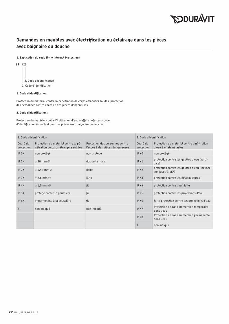
1. Explication du code IP ( = Internal Protection)
2. Code d'identification
1. Code d'identification
1. Code d'identification :
Protection du matériel contre la pénétration de corps étrangers solides, protection
des personnes contre l'accès à des pièces dangereuses
2. Code d'identification :
Protection du matériel contre l'infiltration d'eau à effets néfastes = code
d'identification important pour les pièces avec baignoire ou douche
1. Code d'identification 2. Code d'identification
Degré de
protection
Protection du matériel contre la pé-
nétration de corps étrangers solides
Protection des personnes contre
l'accès à des pièces dangereuses
Degré de
protection
Protection du matériel contre l'infiltration
d'eau à effets néfastes
IP 0X non protégé non protégé IP X0 non protégé
IP 1X ≥ 50 mm Ø dos de la main IP X1protection contre les gouttes d'eau (verti-
cale)
IP 2X ≥ 12,5 mm Ø doigt IP X2protection contre les gouttes d'eau (inclinai-
son jusqu'à 15°)
IP 3X ≥ 2,5 mm Ø outil IP X3 protection contre les éclaboussures
IP 4X ≥ 1,0 mm Ø fil IP X4 protection contre l'humidité
IP 5X protégé contre la poussière fil IP X5 protection contre les projections d'eau
IP 6X imperméable à la poussière fil IP X6 forte protection contre les projections d'eau
X non indiqué non indiqué IP X7Protection en cas d'immersion temporaire
dans l'eau
IP X8Protection en cas d'immersion permanente
dans l'eau
X non indiqué
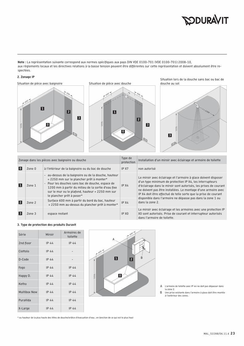
Demandes en meubles avec électrification ou éclairage dans les pièces avec baignoire ou douche
1
600
600
22
50 0
1 2
600
600
22
50 0
12
3
r = 1200
22
50
3
600 600
22
50
0
1
2
3
MAL_52288/06.11.6 23
Note : La représentation suivante correspond aux normes spécifiques aux pays DIN VDE 0100-701 (VDE 0100-701):2008-10,
aux règlements locaux et les directives relations à la basse tension peuvent être différentes sur cette représentation et doivent absolument être re-
spectées.
* ou hauteur de la plus haute des têtes de douche/orifice d'évacuation d'eau ; en fonction de ce qui est le plus haut
3. Type de protection des produits Duravit
L'armoire de toilette avec IP 44 ne doit pas dépasser dans
la zone 2.
Une prise existante dans l'armoire à glace doit être montée
à l'extérieur des zones.
Zonage dans les pièces avec baignoire ou doucheType de
protectionInstallation d'un miroir avec éclairage et armoire de toilette
0 Zone 0 à l'intérieur de la baignoire ou du bac de douche IP X7 non autorisé
1 Zone 1
- au-dessus de la baignoire ou de la douche, hauteur
= 2250 mm sur le plancher prêt à monter*
- Pour les douches sans bac de douche, espace de
1200 mm à partir du milieu de la sortie d'eau fixe
sur le mur ou le plafond, hauteur = 2250 mm sur
le plancher prêt à poser*
IP X4
Le miroir avec éclairage et l'armoire à glace doivent disposer
d'un type minimum de protection IP X4, les interrupteurs
d'éclairage dans le miroir sont autorisés, les prises de courant
ne doivent pas être installées. Le montage d'une armoire avec
IP X4 doit être effectué de telle sorte que la prise de courant
disponible dans l'armoire ne dépasse pas dans la zone 1 ou
dans la zone 2.2 Zone 2 Surface 600 mm à partir du bord du bac, hauteur
= 2250 mm au-dessus du plancher prêt à monter*IP X4
3 Zone 3 espace restant IP X0
Le miroir avec éclairage et les armoires avec une protection IP
X0 sont autorisés. Prise de courant et interrupteur autorisés
dans l'armoire de toilette.
2. Zonage IP
Situation de pièce avec baignoire Situation de pièce avec douche
Situation lors de la douche sans bac ou bac de
douche au sol
Série MiroirArmoires de
toilette
2nd floor IP 44 IP 44
Ciottolo IP 44 -
D-Code IP 44 -
Fogo IP 44 IP 44
Happy D. IP 44 IP 44
Ketho IP 44 IP 44
Multibox New IP 44 IP 44
PuraVida IP 44 IP 44
X-Large IP 44 IP 44

24 MAL_52288/06.11.6
1. Toelichting op IP code ( = Internal Protection)
2. kenmerk (cijfer)
1. kenmerk (cijfer)
1. Kenmerk (cijder):
Bescherming van het item tegen binnendringen van invloeden van buitenaf,
Bescherming van personen tegen toegang tot gevaarlijke delen
2. Kenmerk (cijder):
Bescherming van het item tegen het binnendringen van water wat schade kan
veroorzaken = relevant kencijfer voor ruimtes met baden en/of douche
1. Kencijfer 2. Kencijfer
Bescher-
mingsgraad
Bescherming van het item tegen bin-
nendringen van invloeden van buitenaf
Bescherming van personen tegen
toegang tot gevaarlijke delen
Bescher-
mingsgraad
Bescherming van het item tegen het binnen-
dringen van water wat schade kan veroorzaken
IP 0X niet beschermd niet beschermd IP X0 niet beschermd
IP 1X ≥ 50 mm Ø Handrug IP X1 beschermd tegen drupwater (vertikaal)
IP 2X ≥ 12,5 mm Ø vinger IP X2 Beschermd tegen drupwater (tot 15C helling)
IP 3X ≥ 2,5 mm Ø gereedschap IP X3 Beschermd tegen sproei water
IP 4X ≥ 1,0 mm Ø snoer IP X4 Beschermd tegen spuit water
IP 5X beschermd tegen stof snoer IP X5 Beschermd tegen straal water
IP 6X stof dicht snoer IP X6 Beschermd tegen sterk straal water
X niet aangegeven niet aangegeven IP X7Beschermd enige tijd bij onderdompelen
in water
IP X8Beschermd bij bestendig onderdompelen
in water
X niet aangegeven
Eisen welke aan meubelen gesteld worden met elektra of verlichting in ruimtes met bad en/of douche

1
600
600
22
50 0
1 2
600
600
22
50 0
12
3
r = 1200
22
50
3
600 600
22
50
0
1
2
3
MAL_52288/06.11.6 25
Opmerking: navolgende weergave komt overeen met DIN VDE 0100-701 (VDE 0100-701):2008-10
Landspecifieke normen, plaatselijke voorschriften en de laagspannings-richtlijnen kunnen van navolgende weergave afwijken en dienen onverminderd
gerespecteerd te worden.
* Of de hoogte van de op de hoogste positie vast aangebrachte douchekop of wateruitlaat, al naar gelang wat hoger hangt
3. Beschermingsaard van Duravit produkten
Spiegelkast met IP 44 mag bereik 2 overlappen
Een in de spiegelkast aanwezige wandcontactdoos moet
buiten dit gebeid gemonteerd zijn
Zone indeling in een ruimte met bad of douche Bescherming Installatie van spiegel met verlichting of spiegelkast
0 Bereik 0 in het bad of de douche IP X7 Niet toegestaan
1 Bereik 1
- Boven bad of douchebak hoogte = 2250 mm
boven afgewerkte vloer*
- Bij douchen zonder douchebak afstand van
1200 mm vanaf het middenpunt van de vaste
wateruitlaat aan de wand of uit het plafond*
IP X4
Spiegel met verlichting en spiegelkasten moeten over de minimale
bescherming IP X4 beschikken, lichtschakelaars in de spiegel zijn
toegestaan, wandcontactdozen mogen niet geïnstalleerd worden.
Het aanbrengen van een spiegelkast met IP X4 moet zo geschieden
dat een in de spiegelkast aanwezige contactdoos niet in bereik 1 of
bereik 2 komt te hangen.2 Bereik 2Oppervlak van 600 mm vanuit bad of douchebak
rand Hoogte -2250 mm boven afgewerkte vloer* IP X4
3 Bereik 3 Overige ruimte IP X0Spiegel met verlichting en spiegelkast met IP X0 toegestaan. Wand-
contactdozen en lichtschakelaars in de spiegelkast toegestaan.
2. IP Zone indeling
Situatie bij een ruimte met bad Situatie bij een ruimte met douche
Situatie bij een douche zonder douchebak
of bij vloergelijke douchebakken
Serie SpiegelSpiegel-
kast
2nd floor IP 44 IP 44
Ciottolo IP 44 -
D-Code IP 44 -
Fogo IP 44 IP 44
Happy D. IP 44 IP 44
Ketho IP 44 IP 44
Multibox New IP 44 IP 44
PuraVida IP 44 IP 44
X-Large IP 44 IP 44
26 MAL_52288/06.11.6
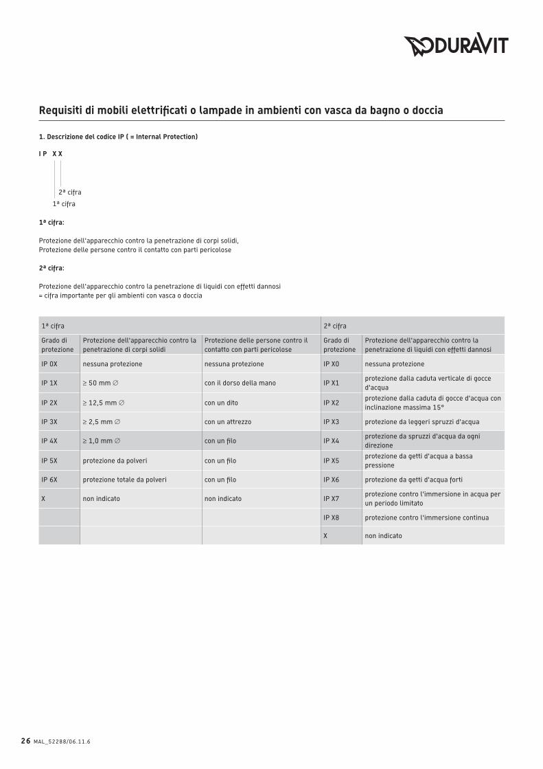
1. Descrizione del codice IP ( = Internal Protection)
2ª cifra
1ª cifra
I P X X
1ª cifra:
Protezione dell'apparecchio contro la penetrazione di corpi solidi,
Protezione delle persone contro il contatto con parti pericolose
2ª cifra:
Protezione dell'apparecchio contro la penetrazione di liquidi con effetti dannosi
= cifra importante per gli ambienti con vasca o doccia
1ª cifra 2ª cifra
Grado di
protezione
Protezione dell'apparecchio contro la
penetrazione di corpi solidi
Protezione delle persone contro il
contatto con parti pericolose
Grado di
protezione
Protezione dell'apparecchio contro la
penetrazione di liquidi con effetti dannosi
IP 0X nessuna protezione nessuna protezione IP X0 nessuna protezione
IP 1X ≥ 50 mm Ø con il dorso della mano IP X1protezione dalla caduta verticale di gocce
d'acqua
IP 2X ≥ 12,5 mm Ø con un dito IP X2protezione dalla caduta di gocce d'acqua con
inclinazione massima 15°
IP 3X ≥ 2,5 mm Ø con un attrezzo IP X3 protezione da leggeri spruzzi d'acqua
IP 4X ≥ 1,0 mm Ø con un filo IP X4protezione da spruzzi d'acqua da ogni
direzione
IP 5X protezione da polveri con un filo IP X5protezione da getti d'acqua a bassa
pressione
IP 6X protezione totale da polveri con un filo IP X6 protezione da getti d'acqua forti
X non indicato non indicato IP X7protezione contro l'immersione in acqua per
un periodo limitato
IP X8 protezione contro l'immersione continua
X non indicato
Requisiti di mobili elettrificati o lampade in ambienti con vasca da bagno o doccia
1
600
600
22
50 0
1 2
600
600
22
50 0
12
3
r = 1200
22
50
3
600 600
22
50
0
1
2
3
MAL_52288/06.11.6 27
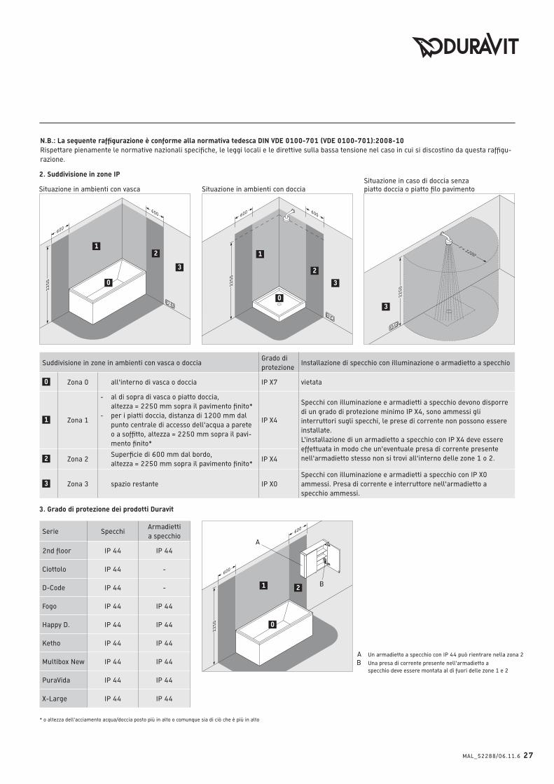
N.B.: La seguente raffigurazione è conforme alla normativa tedesca DIN VDE 0100-701 (VDE 0100-701):2008-10 Rispettare pienamente le normative nazionali specifiche, le leggi locali e le direttive sulla bassa tensione nel caso in cui si discostino da questa raffigu-
razione.
* o altezza dell'acciamento acqua/doccia posto più in alto o comunque sia di ciò che è più in alto
3. Grado di protezione dei prodotti Duravit
Un armadietto a specchio con IP 44 può rientrare nella zona 2
Una presa di corrente presente nell'armadietto a
specchio deve essere montata al di fuori delle zone 1 e 2
Suddivisione in zone in ambienti con vasca o docciaGrado di
protezioneInstallazione di specchio con illuminazione o armadietto a specchio
0 Zona 0 all'interno di vasca o doccia IP X7 vietata
1 Zona 1
- al di sopra di vasca o piatto doccia,
altezza = 2250 mm sopra il pavimento finito*
- per i piatti doccia, distanza di 1200 mm dal
punto centrale di accesso dell'acqua a parete
o a soffitto, altezza = 2250 mm sopra il pavi-
mento finito*
IP X4
Specchi con illuminazione e armadietti a specchio devono disporre
di un grado di protezione minimo IP X4, sono ammessi gli
interruttori sugli specchi, le prese di corrente non possono essere
installate.
L'installazione di un armadietto a specchio con IP X4 deve essere
effettuata in modo che un'eventuale presa di corrente presente
nell'armadietto stesso non si trovi all'interno delle zone 1 o 2.2 Zona 2 Superficie di 600 mm dal bordo,
altezza = 2250 mm sopra il pavimento finito*IP X4
3 Zona 3 spazio restante IP X0
Specchi con illuminazione e armadietti a specchio con IP X0
ammessi. Presa di corrente e interruttore nell'armadietto a
specchio ammessi.
2. Suddivisione in zone IP
Situazione in ambienti con vasca Situazione in ambienti con doccia
Situazione in caso di doccia senza
piatto doccia o piatto filo pavimento
Serie SpecchiArmadietti
a specchio
2nd floor IP 44 IP 44
Ciottolo IP 44 -
D-Code IP 44 -
Fogo IP 44 IP 44
Happy D. IP 44 IP 44
Ketho IP 44 IP 44
Multibox New IP 44 IP 44
PuraVida IP 44 IP 44
X-Large IP 44 IP 44
28 MAL_52288/06.11.6
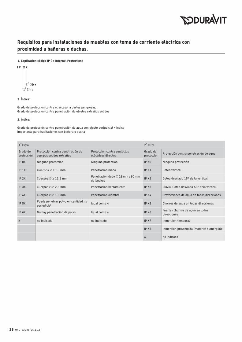
1. Explicación código IP ( = Internal Protection)
2a Cifra
1a Cifra
1. Índice:
Grado de protección contra el acceso a partes peligrosas,
Grado de protección contra penetración de objetos extraños sólidos
2. Índice:
Grado de protección contra penetración de agua con efecto perjudicial = índice
importante para habitaciones con bañera o ducha
1a Cifra 2
a Cifra
Grado de
protección
Protección contra penetración de
cuerpos sólidos extraños
Protección contra contactos
eléctricos directos
Grado de
protecciónProtección contra penetración de agua
IP 0X Ninguna protección Ninguna protección IP X0 Ninguna protección
IP 1X Cuerpos Ø ≥ 50 mm Penetración mano IP X1 Goteo vertical
IP 2X Cuerpos Ø ≥ 12,5 mmPenetración dedo Ø 12 mm y 80 mm de longitud
IP X2 Goteo desviado 15° de la vertical
IP 3X Cuerpos Ø ≥ 2,5 mm Penetración herramienta IP X3 Lluvia. Goteo desviado 60º dela vertical
IP 4X Cuerpos Ø ≥ 1,0 mm Penetración alambre IP X4 Proyecciones de agua en todas direcciones
IP 5XPuede penetrar polvo en cantidad no
perjudicialIgual como 4 IP X5 Chorros de agua en todas direcciones
IP 6X No hay penetración de polvo Igual como 4 IP X6Fuertes chorros de agua en todas
direcciones
X no indicado no indicado IP X7 Inmersión temporal
IP X8 Inmersión prolongada (material sumergible)
X no indicado
Requisitos para instalaciones de muebles con toma de corriente eléctrica con proximidad a bañeras o duchas.

1
600
600
22
50 0
1 2
600
600
22
50 0
12
3
r = 1200
22
50
3
600 600
22
50
0
1
2
3
MAL_52288/06.11.6 29
Advertencia: La presentación siguiente corresponde a la norma DIN VDE 0100-701 (VDE 0100-701):2008-10
Normas específicas de los paises, reglamentos locales y directivas de baja tensión pueden diferir de esta presentación y deben absolutamente estar
respectados.
* o altura del rociador/teleducha más alto de la ducha o salida de agua, según lo que es el más alto
3. Tipo de protección de productos Duravit
Un mueble espejo con IP 44 puede adentrarse en la zona 2
Un enchufe en el interior de un mueble espejo debe estar
montado fuera de las zonas
Subdivisión en zonas en espacios con bañeras o duchaTipo de
protecciónInstalación de espejos con iluminación y muebles espejo
0 Zona 0 dentro de la bañera y ducha IP X7 no permitido
1 Zona 1
- por encima de la bañera o del plato de ducha,
altura = 2250 mm sobre el suelo acabado*
- en duchas sin plato, distancia de 1200 mm
desde el centro de la salida de agua en la
pared o el techo,
altura = 2250 mm sobre el suelo acabado*
IP X4
Espejos con iluminación y muebles espejo deben disponer de un
tipo de protección mínimo de IP X4, interruptores de la luz están
permitidos, enchufes no deben estar instalado.
La instalación de un mueble espejo con IP X4 debe realizarse de
la forma que un enchufe en un mueble espejo no puede adentrar-
se en la zona 1 o la zona 2.2 Zona 2
superficie de 600 mm del borde de la bañera,
altura = 2250 mm sobre el suelo acabado*IP X4
3 Zona 3 espacio restante IP X0
Espejos con iluminación y muebles espejo con IP X0 están per-
mitidos. Enchufe y interruptor de la luz están permitidos en el
mueble espejo.
2. Subdivisión en zonas IP
Situación en espacios con bañera Situación en espacios con ducha
Situación con duchas sin plato respectivamente
platos de ducha ras de suelo
Serie EspejosMuebles
espejo
2nd floor IP 44 IP 44
Ciottolo IP 44 -
D-Code IP 44 -
Fogo IP 44 IP 44
Happy D. IP 44 IP 44
Ketho IP 44 IP 44
Multibox New IP 44 IP 44
PuraVida IP 44 IP 44
X-Large IP 44 IP 44

30 MAL_52288/06.11.6
MAL_52288/06.11.6 31

Duravit AGWerderstr. 3678132 HornbergGermanyPhone +49 78 33 70 0Fax +49 78 33 70 [email protected]
Best
.-N
r. 5
22
88
/06
.11
.6
We r
eserv
e t
he r
igh
t to
make t
ech
nic
al
imp
rove
men
ts a
nd
en
han
ce t
he a
pp
eara
nce
of
the p
rod
ucts
sh
ow
n.