Titre du site Adresse du site (url) Titre du site Adresse du site (url) Auteur.

HOPP
EN - Instructions and warnings for installation and useIT - Istruzioni ed avvertenze per l’installazione e l’uso
FR - Instructions et avertissements pour l’installation et l’utilisationES - Instrucciones y advertencias para la instalación y el usoDE - Installierungs-und Gebrauchsanleitungen und Hinweise
PL - Instrukcje i ostrzeżenia do instalacji i użytkowania
NL - Aanwijzingen en aanbevelingen voor installatie en gebruik
Swing gate opener
HO7124HO7224

2
1 2
290 m
m
180 mm
MIN 400 mm
252 mm
3
4

b
a
a
5
a
b
b
x 4
c
a
a
b
7
7 a
b
c
180°8
10 13
b
11
6
1
6
2 3
A
MAX B
3
b
a
4 5
12
9
OKOK
a

1
2
180°
9 10
1
180°
2
4
OK
3
NO
2
NO
1
3
4 5
28

“A”
12
12 1 22 3
42
1
65
11
2
1
131
36
12
2
45
PP Stop Bluebus hsalF HO7224SLEOpen
1415

1
2
2
1
1
2
3
16 1 2 3
1 217
18 1 32
2
1
4

1
2
12
3
19 1 3
5
2
4
3
2
16 7

EN
English – 1
ENGLISHOriginal instructions
Contents1 - WARNINGS AND GENERAL PRECAUTIONS ........................................ 11.1 - Safety warnings ..................................................................................... 11.2 - Installation warnings .............................................................................. 11.3 - Operation warnings ............................................................................... 1
2 - PRODUCT DESCRIPTION AND INTENDED USE.................................. 13 - INSTALLATION........................................................................................ 23.1 - Preliminary installation checks................................................................ 23.2 - Application limits:................................................................................... 23.3 - Preliminary installation set-up work ........................................................ 23.4 - Installation of gearmotor mod. HO7124 - HO7224................................. 23.5 - Mechanical limit switch adjustment........................................................ 33.6 - Manually releasing and locking the gearmotor........................................ 3
4 - ELECTRICAL CONNECTIONS ............................................................... 34.1 - Gearmotor electrical connections ......................................................... 34.2 - Connection of other devices .................................................................. 34.3 - Routing connected devices ................................................................... 34.4 - Initial start-up and connection check ..................................................... 44.5 - Learning of the connected devices ........................................................ 44.6 - Learning the mechanical stop positions ................................................. 44.7 - Gate leaf movement check .................................................................... 55 – TESTING AND COMMISSIONING ......................................................... 55.1 - Testing................................................................................................... 55.2 - Commissioning...................................................................................... 5
6 – CONTROL PANEL PROGRAMMING ..................................................... 66.1 - Level 1 programming (ON-OFF functions) .............................................. 66.2 - Level 2 programming (adjustable parameters)........................................ 66.3 - Special functions ................................................................................... 86.4 - Deleting the memory.............................................................................. 87 – TROUBLESHOOTING... (troubleshooting guide) .................................. 9
8 - FURTHER INFORMATION .................................................................... 108.1 - Connecting a radio receiver ................................................................. 108.2 - Connecting and installing the buffer battery mod. PS124..................... 108.3 - Connecting the Oview programmer ..................................................... 118.4 - Connecting the solar power system Solemyo ...................................... 118.5 - Connecting the external release system Kio......................................... 11
9 - PRODUCT MAINTENANCE.................................................................. 11
PRODUCT DISPOSAL ............................................................................... 11
TECHNICAL SPECIFICATIONS OF PRODUCT ......................................... 12
Product lifetime.......................................................................................... 13
CE DECLARATION OF CONFORMITY ...................................................... 14
APPENDIX ..................................................................................................... IInstructions and warnings for the user ............................................................ IIImages.......................................................................................................... IX
1.1 - Safety warnings• IMPORTANT! – This manual contains important instructions and warn-
ings regarding safety. Incorrect installation may cause serious injury. Beforecommencing work, all sections of the manual must be read carefully. If inany doubt, suspend installation and call the Nice Support Service for clarifi-cation.
• IMPORTANT! – This manual contains important instructions. Keep itfor future maintenance work and disposal of the product.
• IMPORTANT! – Under the latest European legislation, automatic doorand gate installations must be compliant with the standards specifiedin Directive 2006/42/EC (formerly 98/37/EC) (the Machinery Directive)and the standards EN 12445, EN 12453, EN 12635 and EN 13241-1 inparticular, which enable conformity of the automated functionality tobe de clared. In the light of the above, all work involving installation,connection, testing and maintenance of the product must be carriedout exclusively by qualified and competent technicians!
1.2 - Warnings for installation• Before commencing the installation, check if the product is suitable for the de-
sired type of use (see “Usage limitation” paragraph 3.2 and the “Product te -chnical specifications”). If it is not suitable, DO NOT continue with theinstallation.
• The contents of this manual refer to a standard system as described in fig. 3.• All installation and maintenance work must be carried out with the au to-
mation system disconnected from the electricity supply. If the power dis-connection device cannot be seen from where the automation system ispositioned, then before starting work a notice must be attached to the dis-connection device bearing the words “CAUTION! MAINTENANCE IN PRO -GRESS”.
• The Control unit must be connected to an electricity supply line equipped withprotective earthing.
• Handle the product with care during installation, taking care to avoid crushing,denting or dropping it, or contact with liquids of any kind. Keep the productaway from sources of heat and naked flames. Failure to observe the abovecan damage the product, and increase the risk of danger or malfunction.Should this occur, suspend installation work immediately and contact the NiceSupport Service.
• Do not modify any part of the product. Prohibited modifications can only leadto malfunctions. The manufacturer declines all responsibility for damage re-sulting from unauthorized changes made to the product.
• If the gate or door being automated has a pedestrian gate, then the systemmust include a control device that will inhibit the operation of the motor whenthe pedestrian gate is open.
• The product’s packaging material must be disposed of in full compliance withlocal regulations.
1.3 - Warnings for use• The product is not intended for use by persons, including children, with limited
physical, sensory or mental capacities, or who lack experience or knowledge,unless supervised or trained in the use of the product by a person responsi-ble for their safety.
• Any children near the automation system must be kept under supervision toensure that they do not play with it.
• Do not allow children to play with the fixed control devices. Keep remote con-trol devices out of the reach of children.
WARNINGS AND GENERAL PRECAUTIONS1
The devices making up this product are intended for use in the automation ofgates or doors with swing leafs for residential and industrial applications. CAU-TION! – Any other use than as specified herein or in environmental con-ditions other than as stated in this manual is to be considered improperand is strictly prohibited!The main part of the automation comprises one or two gearmotors (accord-ing to the number of leafs to be automated), each equipped with a DC motorand a straight tooth gear reducer. One of the gearmotors (mod. HO7124) is fit-ted with a control unit that manages operation. The control unit comprises aboard with radio receiver, for receiving commands sent by the transmitter. Italso has a provision for connection to various devices belonging to the Operasystem, the Bluebus system and the Solemyo solar power system; see chap-ter 8 – Further information. It can house a buffer battery (mod. PS124, optionalaccessory) which in the event of a power failure guarantees a number of au-tomation manoeuvres in the subsequent hours.In the event of a power failure, the gate leafs can also be moved by unlock-ing the gearmotor by means of the special key; see paragraph 3.6.Other accessories available include the receivers with “SM” connector (SMXI,OXI, etc.), see chapter 8 - Further information.
PRODUCT DESCRIPTION AND INTENDED USE2

EN
2 – English
3.1 - Pre-installation checksBefore going ahead with the installation, check the integrity of the product com-ponents, and ensure the model chosen is suitable for its intended use and forthe environment in which it is to be installed.• Check that all the material to be used is in excellent condition and suitable for
its intended use.• Check that the ground-mounted mechanical stops (not supplied), are present
both when opening and closing the automation system.• Check that the mechanical structure of the gate is suitable for the installation
of automation and compliant with locally applicable regulations (if necessary,refer to the label on the gate). This product cannot be used to automate a gatewhich is not already in good, safe working order, neither can it fix faults causedby incorrect installation or poor maintenance of the gate.
• Check that the operating conditions of the devices are compatible with theusage limitation declared (see paragraph 3.2).
• Move the gate leaves manually in both directions and ensure that the resist-ance to movement is constant at all points of travel (there should not be anypoints where more force or less is required).
• Bring the gate leaves manually into a position at random, then let go and checkthat they remain stationary.
• Check that the gearmotor fixing zone is compatible with its overall dimensions(fig. 1).
• Check that the place where the gearmotor is to be installed allows enoughspace for its arm to execute its full range of movement (fig. 2).
• Check that there is sufficient room around the gearmotor for it to be releasedmanually when required.
• Ensure that the surfaces on which the various devices are to be installed arestrong and capable of ensuring a firm hold.
• Ensure that each device is installed in a position which is protected and doesnot expose it to accidental impacts.
• Ensure that all the electrical cables to be used are the type listed in Table 1.3.2 - Application limitsBefore starting gearmotor installation, perform the following checks:• ensure that the leaf to be motor-powered remains within the limits specified in
Graph 1;• maximum leaf width: 2,4 m (with weight up to max. 160 kg);• maximum leaf weight: 250 kg (with width up to max. 1,5 m);• check limits specified in the table of “Product technical specifications”;• minimum width of space for gearmotor installation: 170 mm;• The arm fixing bracket must be located in a resistant area of the leaf (for exam-
ple the frame), to guarantee a solid and safe fixture.
3.3 - Preliminary installation set-up workFig. 3 provides an example of an automation system, produced using Nice com-ponents (some components may not be present in the kit):a - Gearmotor with control unit model HO7124b - Gearmotor without control unit model HO7224c - Flashing light MLBTd - Pair of photocells model MOFBe - Digital keypad (mod. MOTB) - Transponder badge reader (mod. MOMB) –
Key-operated selector switch (mod. MOSE)f - Pair of posts for photocellsg - Mechanical stop on closingh - Electric lockThese parts are positioned according to a typical standard layout. With refer-ence to fig. 3, locate the approximate position for installation of each componentenvisaged in the system. Important – Before installation, prepare the electriccables required for the system, with reference to fig. 4 and “Table 1 - Techni-cal specifications of electric cables”.Caution – When laying the ducting for routing the electrical cables, also takeinto account that due to possible deposits of water in the routing ducts, the con-nection pipelines must not create condensate in the control unit, with conse-quent damage to the electronic circuits.3.4 - Installation of gearmotor mod. HO7124 - HO7224
WARNINGS• Incorrect installation may cause serious physical injury to those working
on or using the system.• Before starting automation assembly, make the preliminary checks as
described in paragraphs 3.1 and 3.2.01. Measure position “B” (fig. 5);02. Move the leaf to the maximum required opening position and check that
the angle found remains within the values shown on Graph 2;03. On Graph 2, with value “B” and the opening angle, calculate value “A” (fig.
6). Example: if “B” is 100 mm and the required angle is 100°, value “A” isapprox. 180 mm.
04. Mount the gearrmotor fixing bracket on the wall in a horizontal position, asshown in fig. 7: use suitable plugs, screws and washers (not supplied);
05. Fix the gearmotor to the previously mounted bracket, as shown in fig. 7-3:use the screw supplied (M4.8x13);
06. Then fix the curved arm to the straight arm, using the pin and Benzingsnap ring (fig. 7-4); fix the leaf fixing bracket to the curved arm, using thepin and Benzing snap ring (fig. 7-4);
07. Manually release the gearmotor (fig. 7-6), see paragraph 3.6;08. At this point, determine the zone for fixing the bracket ion the gate leaf, setting
the gearmotor arms to the maximum extension (fig. 7-7): it is important toposition the bracket at the point furthest from the position of the gearmotor;
INSTALLATION3
GRAPH 2 A
B
110
050
100150200
130 150 170 200 220 250 300
Connection Cable type Maximum admissible lengthA: CONTROL UNIT POWER SUPPLY cable 1 Cable 3 x 1,5 mm2 30 m (note 1)B: ELECTRIC LOCK Cable 1 Cable 2 x 1 mm2 6 mC: BLUEBUS DEVICE cable 1 Cable 2 x 0,5 mm2 20 m (note 2)D: KEY-OPERATED SELECTOR SWITCH cable 2 cables 2 x 0,5 mm2 (note 3) 50 mE: GEARMOTOR POWER SUPPLY Cable 1 Cable 3 x 1,5 mm2 10 mF: FLASHING LIGHT with aerial cable 1 Cable 2 x 1 mm2 20 m
1 RG58 type shielded cable 20 m (less than 5 m recommended)Note 1 – If the power cable exceeds a length of 30 m, use a cable with a larger section (3x2.5 mm2); in this case earthing is required in the vicinity of the automation.Note 2 – If the Bluebus cable exceeds a length of 20 m, up to a maximum of 40 m, use a cable with a larger section (2 x 1 mm2).Note 3 – These 2 cables may be replaced with a single cable of 4 x 0,5 mm2.CAUTION! – The cables used must be suited to the type of environment of the installation site.
TABLE 1 – Technical specifications of electric cables (fig. 4)
250
150
1.0 1.2 1.4 1.6 1.8 2.0 2.2 2.4
175
200
225
250
GRAPH 1
Leaf width (m)
Leaf
weigh
t (kg)

EN
English – 3
4.1 - Gearmotor electrical connectionsCaution! – Only make the electrical connections after installing thegearmotor.
WARNINGS!– Connections must be made exclusively by qualified personnel.– All electrical connections must be made with the unit disconnectedfrom the mains power supply and with the buffer battery disconnected(if present).– The electrical power line must be fitted with a device that enables com-plete disconnection of the automation from the mains. The disconnectiondevice must have a gap between contacts that ensures complete discon-nection in the conditions of overvoltage category III, in compliance withinstallation regulations.01. Open the cover of the gearmotor (fig. 12-1);02. Route the power cable and other electric cables through the hole on the
lower section of the gearmotor (afb. 12-2);03. First connect the power cable of the motor with the control unit HO7124:
loosen the cable clamp (fig. 12-3) and connect the power cable as shown infig. 12-4; then secure the cable by means of the cable clamp (fig. 12-5);
04. Then connect the cable powering the motor without control unit (HO7224) asshown in fig. 13;
05. Lastly connect the electric cables of the various devices present, with referenceto fig. 11 and paragraph 4.3. Note – To facilitate cable connections, the termi-nals can be removed from their seats;
06. In the Table 2 identify the type corresponding to the system to be pro-grammed and if necessary, on the control unit, set the selector JA andjumper JB as described;
07. Close the gearmotor cover (fig. 12-6).
4.2 - Connection of other devicesIf further devices present in the system need to be powered, for example atransponder card reader or the key selector light, these devices can be con-nected to the control unit using terminals “P.P. (positive)” and “STOP (negative)”(fig. 11). The power supply voltage is 24 Vdc, -30% ÷ +50%, with maximumavailable current 200 mA.Note – The voltage present on terminals “P.P.” and “STOP” remains connectedeven when the “Stand By” function is activated on the card.4.3 -Routing connected devicesTo enable control unit recognition of the devices connected to the BlueBus sys-tem, they need to be routed. This operation must be performed by positioning
09. Drill the leaf and fix the bracket using suitable screws (not supplied) (figs.7-8, 7-9 and 7-10);
10. Before locking the gearmotor, adjust the mechanical opening limiter asrequired (paragraph 3.5).
3.5 - Adjusting the mechanical opening limiter01. Manually move the gate leafs to the maximum opening position;02. Rotate the plastic disk on the lower section of the gearmotor, to position
the aperture under the arm as shown in fig. 8;03. Insert the limiter in the first possible place: try to insert as shown in fig. 8
(opening direction);04. Rotate the disk to prevent the limiter from dropping, moving the aperture to
the position shown in fig. 8; for more precise adjustments, use the adjust-ment screw (fig. 8);
05. If there is no floor-mounted stop in the system, this procedure must berepeated from point 01 also for the closing limiter;
06. Lastly, tighten the disk fixing nut fully down (fig. 8) to ensure that it does notrotate accidentally.
3.6 - Manually releasing and locking the gearmotorThe gearmotor is equipped with a mechanical locking system to enable manu-al opening and closing of the gate.These manual operations should only be performed in the event of a power fail-ure, malfunctions or during the installation procedures.Releasing (fig. 9):01. Insert the key;02. Turn the key anti-clockwise (180°);03. At this point the leaf can be moved manually to the required position.Locking (fig. 10):01. Turn the key clockwise through 180°;02. Remove the key.
The electrical connection of the various devices (photocells, digital keyboard,transponder card readers, etc.) contained in the automation with the control unitmust be made by means of the Nice “Bluebus” system.
Description of electrical connections (fig. 11)AERIAL input for the radio receiver aerialFLASH output for 1 flashing light with 12V (maximum 21W) bulb. [*]ELS output for 12Vac (maximum 15VA) electric lock. [*]BLUEBUS input for compatible devices (MOFB, MOFOB, MOB and MOTB);
they are connected in parallel using two conductors throughwhich both the electricity supply and the communication signalstravel; no polarity needs to be observed. The electrical connec-tion to be used is of the parallel type and no polarity needs to beobserved. During the learning stage, the control unit will recog-nise individually all devices connected to it thanks to a uniquecode. Each time a device is added or eliminated, it will be nec-essary to make the control unit perform the learning operation(see paragraph 4.5).
STOP input for devices that cause the immediate interruption of themanoeuvre in progress (with a short reverse run); NO and NCcontacts, as well as devices with 8.2 kΩ constant resistanceoutput (sensitive edges) can be connected to this input. Eachdevice connected to this input is recognised individually by thecontrol unit during the learning stage (paragraph 3.4); in thisstage, if the control unit detects any variations with respect tothe learned state, it causes a STOP. One or more devices of thesame or different kinds can be connected to this input:– connect a number of NO devices in parallel without quantitylimits;– several NC devices can be connected in series, with no limitsas to quantity;– connect 2 devices with 8.2 kΩ constant resistance output inparallel. If there are more than 2 devices, they must be connect-ed in a cascade with just one 8.2 kΩ termination resistance;– connect 2 NO and NC devices in parallel, placing a 8.2 kΩresistance in series on the NC contact (this also allows for acombination of three devices NO - NC and 8.2 kΩ)
P.P. input for devices which control Step-by-Step manoeuvres. NOcontacts can be connected to this input
OPEN input for control devices, which intervene to cause partial open-ing 1 manoeuvre; possibility of connecting NO type contacts
M output for gearmotor without control unit (HO7224)[*] The outputs FLASH and ELS can be programmed with other functions(see “TABLE 5 – Level 1 functions”; or via the Oview programmer; see para-graph 8.3).
ELECTRICAL CONNECTIONS4 Overlapping leaf
Overlapping leaf
Overlapping leaf
HO7224 HO7124
HO7124HO7224
HO7124 HO7224
HO7224 HO7124
HO7124 HO7224
HO7124
HO7124
TABLE 2
Overlapping leafHO7124 HO7224

EN
4 – English
ing). There are three ways to perform this procedure: automatic, manual orcombined.In automatic mode, the control unit learns the positions of the mechanicalstops and calculates the most suitable offset value for the leafs (SA and SC,fig. B).In manual mode, the six positions of the mechanical stops fig. B are pro-grammed one by one, moving the leafs to the required points. The position toprogram is identifiable by the flashing status of one of the 6 leds (L1-L6), seeTable 4.In combined mode, the automatic procedure can be performed and then, usingthe manual procedure, one or more positions may be modified, with the excep-tion of positions “0” and “1” (fig. B) which coincide with the positions of themechanical stops.
4.6.1 - Learning in automatic mode01. Press and hold keys “Set” and “”at the same time;02. Release the keys when leds “L3” and “L4” start flashing quickly (after
approx. 3 seconds);03. Ensure that the automation completes the following sequences of ma -
noeuvres:a - Low speed closure of gearmotor M1 through to the mechanical stopb - Low speed closure of gearmotor M2 through to the mechanical stopc low speed opening of gearmotor M2 and gearmotor M1 through to themechanical stopd - High speed closure of gearmotors M1 and M2
Warnings:– If the first manoeuvre performed by one or both the leafs is not closing, press
“⊳” or “” to stop the learning phase; then check the position of selector JAand jumper JB (see Table 2) or check connection polarity of the motor with-out control unit (HO7224).
– If the first closing manoeuvre is not controlled by M1, press “⊳” or “” tostop the learning phase; then check the position of selector JA and jumperJB, see Table 2;
04. At the end of the Closing manoeuvre of the 2 motors (d), leds “L3” and“L4” turn off to indicate the that the procedure has been completed cor-rectly.
Warnings:– During the automatic learning procedure, if a photocell trips or a device con-
nected to the “stop” input is activated, the procedure is interrupted and ledL1 starts flashing. To resume the learning process, the procedure must bestarted again from point 01;
– The automatic learning procedure can be repeated at any time, also afterinstallation; for example following modifications to the position of themechanical stops.
4.6.2 - Learning in manual modeCaution! – From step 03 onwards:– to move from led L1 to L6, briefly press key ⊳ or (the led flashes to indi-
cate the current position);– to move the motor in one or the other direction, press and hold key ⊳ or .01. Press and hold keys “Set” and “” at the same time.02. Release the keys when led “L1” starts flashing (after approx. 1 second);
Note – After 3 seconds have elapsed, if the keys “Set” and “” are not re-leased, the “automatic learning” procedure is started up, and not the man-ual procedure.
the electric jumper correctly on each device; see the relative instruction manualof individual devices: see fig. A and Table 3.To route other devices, consult the relative instruction manuals. At the end ofthe installation procedure, or after removing photocells or other devices, thedevice learning procedure must be performed as described in paragraph 4.5.
4.4 - Initial start-up and electrical connectionsAfter powering up the control unit, perform the following checks:• After a few seconds, make sure that the “Bluebus” LED (fig. 15) flashes regu-
larly with a frequency of about one flash per second.• Make sure that the LEDs on the photocells (fig. 15) flash (both on TX and RX).
The type of flashing is not important during this stage.• Make sure that the flashing light connected to the FLASH output is off.If the above conditions are not satisfied, switch off the power supply to the con-trol unit and check the electrical connections previously made.
4.5 - Learning of the devices connectedAfter the initial power-up, the control unit must be able to recognise the devicesconnected to the “Bluebus” and “Stop” inputs.IMPORTANT ! – The learning procedure must be performed even if no de-vice is connected to the control unit.The control unit is able to recognise the various connected devices individuallythrough the self-learning procedure and detect possible faults. For this reason itis necessary to perform self-learning every time a new device is added or an ex-isting device is removed.To indicate when the self-learning procedure is required, LEDs L1 and L2 on thecontrol unit (fig. 15) emit a number of slow flashes:01. Press and hold down ⊳ and “Set” keys at the same time (fig. 15).02. Release the keys when LEDs L1 and L2 start flashing quickly (after approx.
3 seconds).03. Wait a few seconds for the control unit to complete the device learning
phase.04. At the end of this phase, the “Stop” LED must be lit and LEDs “L1” and
“L2” must be turned off (LEDs L3 and L4 may start flashing).4.6 - Learning the mechanical stop positions After learning the connected devices (paragraph 4.6), the positions of themechanical stops must also be learnt (maximum opening and maximum clos-
TABLE 3 - PHOTOCELL ADDRESSESPhotocell JumpersFOTOExternal photocell h = 50 with tripon closure (stops and inverts movement)FOTO IIExternal photocell h = 100 with tripon closure (stops and inverts movement)FOTO 1Internal photocell h = 50 with tripon closure (stops and inverts movement)and opening (stops and restartswhen photocell is disengaged)FOTO 1 IIInternal photocell h = 100 with tripon closure (stops and inverts movement)and opening (stops and restartswhen photocell is disengaged)FOTO 2Internal photocell with tripon opening (stops and inverts movement)FOTO 2 IIInternal photocell with tripon opening (stops and inverts movement)FOTO 3CONFIGURATION NOT ADMITTED
A
TABLE 4Position Led DescriptionPosition 0(motor 1)Position 0(motor 2)Position SA(motor 2)Position SC(motor 1)Position 1(motor 1)Position 1(motor 2)
Maximum closing position: when leaf 1 reaches closing me-chanical stopMaximum closing position: when leaf 2 reaches closing me-chanical stopOpening offset: when leaf 2 passes this position the opening ofleaf 1 beginsClosing offset: when leaf 1 reaches this position, leaf 2 beginsto closeMaximum opening position: when leaf 1 reaches the openingmechanical stopMaximum opening position: when leaf 2 reaches the openingmechanical stop
L1
L2
L3
L4
L5
L6
0
1 1SC
SA
0M1 M2
B POSITIONS

EN
English – 5
03. • LED L1 flashes: position 0 of M1To bring motor 1 to position 0 (fig. B): press and hold down the ⊳ or keys. On reaching the position, release the key to stop the manoeuvre. Tomemorise the position, press and hold down the “Set” key for at least 3seconds and then release it (after 2 seconds LED L1 remains on and onreleasing the “Set” key LED L2 begins flashing).
• LED L2 flashes: position 0 of M2To bring motor 2 to position 0 (fig. B): press and hold down the ⊳ or keys. On reaching the position, release the key to stop the manoeuvre. Tomemorise the position, press and hold down the “Set” key for at least 3seconds and then release it (after 2 seconds LED L2 remains on and onreleasing the “Set” key LED L3 begins flashing).
• LED L3 flashes: position SA of M2To bring motor 2 to position SA (fig. B): press and hold down the ⊳ or keys. On reaching the position, release the key to stop the manoeuvre. Tomemorise the position, press and hold down the “Set” key for at least 3seconds and then release it (after 2 seconds LED L3 remains on and on re-leasing the “Set” key LED L4 begins flashing).
• LED L4 flashes: position SC of M1To bring motor 1 to position SA (fig. B): press and hold down the ⊳ or keys. On reaching the position, release the key to stop the manoeuvre. Tomemorise the position, press and hold down the “Set” key for at least 3seconds and then release it (after 2 seconds LED L4 remains on and on re-leasing the “Set” key LED L5 begins flashing).
• LED L5 flashes: position 1 of M1To bring motor 1 to position 1 (fig. B): press and hold down the ⊳ or keys. On reaching the position, release the key to stop the manoeuvre. Tomemorise the position, press and hold down the “Set” key for at least 3seconds and then release it (after 2 seconds LED L5 remains on and onreleasing the “Set” key LED L6 begins flashing).
• LED L6 flashes: position 1 of M2To bring motor 2 to position 1 (fig. B): press and hold down the ⊳ or keys. On reaching the position, release the key to stop the manoeuvre. Tomemorise the position, press and hold down the “Set” key for at least 3seconds and then release it to exit programming (after 2 seconds LED L6remains on until the “Set” key is released).
Note – Manual programming of a system with a single gearmotor:proceed as described at the start of this paragraph from step 01. At step 03proceed as follows:- program the positions of leds L1 (0 of M1) and L5 (1 of M1) as follows:
press and hold “Set” for at least 3 seconds and then release (after 2 sec. theled remains lit and on release of the “Set” key the next led starts to flash).
- do not program the positions of leds L3 (SA of M2) - L4 (SC of M1): tomove between positions, briefly press “⊳” or “”.
4.6.3 - Learning in combined modePerform this procedure after completing the automatic learning cycle:01. Press and hold keys “Set” and “” at the same time.02. Release the keys when led “L1” starts flashing (after approx. 1 second);
Note – After 3 seconds have elapsed, if the keys “Set” and “” are not re-leased, the “automatic learning” procedure is started up, and not the man-ual procedure.
03. Briefly press key “⊳” or “” to move the flashing led (L1-L6) to the positionto be programmed and proceed for each position, as described in step 03of the manual learning procedure (paragraph 4.7.2).Repeat this operation for all other positions to be modified.
To complete the manual learning process, press key “” repeatedly to move theled that flashing beyond position L6.4.7 - Checking movement of gate leafsAt the end of the learning procedure, it is advisable to make the control unit per-form a few opening and closing manoeuvres to ensure that the gate moves cor-rectly and to check for installation or setting defects.01. Press “Open” and ensure that the opening manoeuvre comprises the ac-
celeration phase, the constant speed phase and the deceleration phase.Check correct offset of the leafs on opening. At the end of the manoeuvre,the leafs must be perfectly open on the mechanical opening stop;
02. Press the “Close” key and check that the closure manoeuvre includes theacceleration, constant speed and deceleration phases. Check that the leafclosure offset is correct. At the end of the manoeuvre, the leafs must beperfectly closed on the mechanical closure stop.
03. Make sure that the flashing light flashes at intervals of 0.5 sec on, 0.5 secoff during manoeuvres.
These are the most important phases in the installation of the automation sys-tem, in order to guarantee maximum system safety. Testing can also be used tocheck the devices in the automation system regularly. The automation systemtesting and commissioning phases must be carried out by qualified expertswho must be responsible for determining the tests necessary to check thesolutions adopted vis-à-vis the risks involved, and to check the observance ofall legal and regulatory obligations: in particular all the requirements of the EN12445 standard which sets forth the test methods for checking automatedgates.Additional devices must undergo specific testing, both in terms of functionalityas well as their correct interaction with POP; please refer to the relevant individ-ual instruction manuals.5.1 - TestingThe sequence of steps to take to carry out testing refers to a typical system (fig. 3):1 Ensure that everything stated in the “Installation warnings” chapter has been
observed.2 Release the gearmotors manually and check that when you operate the leaf,
at the point designed especially for the manual manoeuvre, the leaves caneither be opened or closed with a force of less than 390 N.
3 Secure the gearmotors (see chapter 3.6).4 Using the control devices (transmitter, command button, key selector, etc.),
perform some Gate Opening, Closing and Stop tests, making sure the move-ment of the leaves corresponds with each test. It is a good idea to carry outseveral tests in order to evaluate the movement of the leaves and pinpointany assembly or adjustment defects as well as to check for any particularpoints of friction.
5 Check operation of all system safety devices one at a time (photocells, sen-sitive edges etc.). When a device trips, the BLUEBUS” led on the control unitemits 2 quick flashes to confirm recognition.
6 If the hazardous situations caused by the movement of the leaves have beensafeguarded by limiting the force of impact, the force must be measured inaccordance with the EN 12445 standard and, if necessary, if the control ofthe “gearmotor force” is used as an aid to the system to reduce the force ofimpact, try and then find the adjustment that achieves the best results.
7 Permanently affix a label showing how to manually release the gearmotor ina zone adjacent to the automation.
5.2 - CommissioningCommissioning can only take place once all the testing phases have beencarried out successfully.1 Put together the automation system’s technical file, which should include
the following documents: an overall diagram of the automation system, thediagram of the electrical connections made, the current risk analysis andthe related solutions adopted, the manufacturer’s declaration of conformityfor all the devices used and the declaration of conformity filled in by the in -staller.
2 Affix a data plate onto the gate which specifies the following information, atleast: the type of automation system, the name and address of the manu-facturer (responsible for the commissioning), the serial number, the year ofmanufacture and the EC mark.
3 Fill in the declaration of conformity of the automation system and hand it overto its owner.
4 Fill in and hand over to the owner of the automation system the “User’sguide” of the automation system.
5 Fill in and hand over to the owner of the automation system the “Mainte-nance schedule” which contains instructions on the maintenance of all thedevices in the automation system.
6 Before commissioning the automation system, inform the owner of all thehazards and residual risks entailed.For all the documentation mentioned, the Nice technical support service pro-vides the following: instruction manuals, guides and precompiled forms. Alsovisit: www.nice-service.com
TESTING AND COMMISSIONING5
EN
6 – English
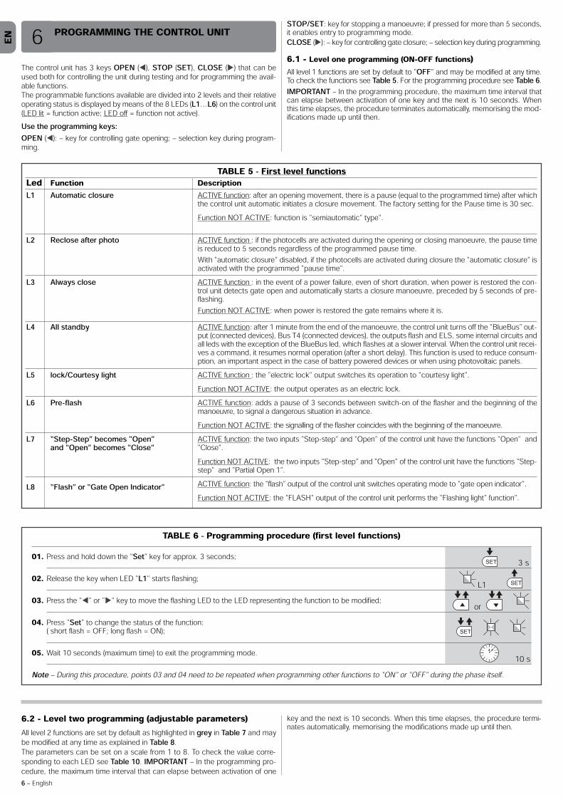
The control unit has 3 keys OPEN (⊳), STOP (SET), CLOSE () that can beused both for controlling the unit during testing and for programming the avail-able functions.The programmable functions available are divided into 2 levels and their relativeoperating status is displayed by means of the 8 LEDs (L1…L6) on the control unit(LED lit = function active; LED off = function not active).Use the programming keys:OPEN (⊳): – key for controlling gate opening; – selection key during program-ming.
STOP/SET: key for stopping a manoeuvre; if pressed for more than 5 seconds,it enables entry to programming mode.CLOSE (): – key for controlling gate closure; – selection key during programming.6.1 - Level one programming (ON-OFF functions)All level 1 functions are set by default to “OFF” and may be modified at any time.To check the functions see Table 5. For the programming procedure see Table 6.IMPORTANT – In the programming procedure, the maximum time interval thatcan elapse between activation of one key and the next is 10 seconds. Whenthis time elapses, the procedure terminates automatically, memorising the mod-ifications made up until then.
PROGRAMMING THE CONTROL UNIT6
TABLE 5 - First level functionsLed Function DescriptionL1 Automatic closure
L2 Reclose after photo
L3 Always close
L4 All standby
L5 lock/Courtesy light
L6 Pre-flash
L7 “Step-Step” becomes “Open”and “Open” becomes “Close”
L8 “Flash” or “Gate Open Indicator”
ACTIVE function: after an opening movement, there is a pause (equal to the programmed time) after whichthe control unit automatic initiates a closure movement. The factory setting for the Pause time is 30 sec.Function NOT ACTIVE: function is “semiautomatic” type”.
ACTIVE function : if the photocells are activated during the opening or closing manoeuvre, the pause timeis reduced to 5 seconds regardless of the programmed pause time.With “automatic closure” disabled, if the photocells are activated during closure the “automatic closure” isactivated with the programmed “pause time”.ACTIVE function : in the event of a power failure, even of short duration, when power is restored the con-trol unit detects gate open and automatically starts a closure manoeuvre, preceded by 5 seconds of pre-flashing.Function NOT ACTIVE: when power is restored the gate remains where it is.ACTIVE function: after 1 minute from the end of the manoeuvre, the control unit turns off the “BlueBus” out-put (connected devices), Bus T4 (connected devices), the outputs flash and ELS, some internal circuits andall leds with the exception of the BlueBus led, which flashes at a slower interval. When the control unit recei-ves a command, it resumes normal operation (after a short delay). This function is used to reduce consum-ption, an important aspect in the case of battery powered devices or when using photovoltaic panels.ACTIVE function : the “electric lock” output switches its operation to “courtesy light”.Function NOT ACTIVE: the output operates as an electric lock.ACTIVE function: adds a pause of 3 seconds between switch-on of the flasher and the beginning of themanoeuvre, to signal a dangerous situation in advance.Function NOT ACTIVE: the signalling of the flasher coincides with the beginning of the manoeuvre.ACTIVE function: the two inputs “Step-step” and “Open” of the control unit have the functions “Open" and“Close”.Function NOT ACTIVE: the two inputs “Step-step” and “Open” of the control unit have the functions “Step-step" and “Partial Open 1”.ACTIVE function: the “flash” output of the control unit switches operating mode to “gate open indicator”.Function NOT ACTIVE: the "FLASH" output of the control unit performs the “Flashing light” function”.
TABLE 6 - Programming procedure (first level functions)01. Press and hold down the “Set” key for approx. 3 seconds;
02. Release the key when LED “L1” starts flashing;
03. Press the “⊳” or “” key to move the flashing LED to the LED representing the function to be modified;
04. Press “Set” to change the status of the function:( short flash = OFF; long flash = ON);
05. Wait 10 seconds (maximum time) to exit the programming mode.
Note – During this procedure, points 03 and 04 need to be repeated when programming other functions to “ON” or “OFF” during the phase itself.
SET
SET
SET
L1
or
3 s
10 s
6.2 - Level two programming (adjustable parameters)All level 2 functions are set by default as highlighted in grey in Table 7 and maybe modified at any time as explained in Table 8.The parameters can be set on a scale from 1 to 8. To check the value corre-sponding to each LED see Table 10. IMPORTANT – In the programming pro-cedure, the maximum time interval that can elapse between activation of one
key and the next is 10 seconds. When this time elapses, the procedure termi-nates automatically, memorising the modifications made up until then.

EN
English – 7
TABLE 7 - Second level functionsInput LED Parameter Led Value Description(level)L1 L1
L2L3L4L5L6L7L8
5 seconds15 seconds30 seconds45 seconds60 seconds80 seconds120 seconds180 seconds
Sets the pause time, namely the timewhich lapses before automatic clo-sure. This will only take effect if closingis active.
Pause time
L2 L1L2L3L4
L5
L6L7
L8
Open – stop – close – stopOpen – stop – close – stop Open – stop – close – stopApartment block:• In the opening manoeuvre the “Step by Step” and “Open” commandshave no effect; the “Close” command causes the movement to be inverted,i.e. the closure of the leaf.• In the closure manoeuvre the “Step by Step” and “Open” commands cau-se the movement to be inverted, i.e. the leaf to open; the “Close” commandhas no effect.Apartment block 2: • In the opening manoeuvre the “Step by Step” and “Open” commandshave no effect; the “Close” command causes the movement to be inverted,i.e. the closure of the leaf. If the transmitted command persists for morethan 2 seconds, a “Stop” is performed.• In the closure manoeuvre the “Step by Step” and “Open” commandscause the movement to be inverted, i.e. the leaf to open; the “Close” com-mand has no effect. If the transmitted command persists for more than2 seconds, a “Stop” is performed.Step-by-step 2 (less than 2 sec. generates partial opening )Hold-to-run:the manoeuvre is performed only if the transmitted command persists; ifthe command is interrupted the manoeuvre stops.Opening in semi-automatic mode, closing in hold-to-run mode
Sets the sequence of commands as-sociated with the “Step-by-Step”,“Open”, or “Close” inputs or the radiocontrol.Note – When setting L4, L5, L7 andL8, the behaviour of the “Open” and“Close” commands is also modified.
Step bystepfunction
L3 L1L2L3L4L5L6L7L8
Very slowSlowMediumFastVery fastExtremely fastFast opening, Slow ClosingExtremely fast Opening, Medium Closing
Sets the motor speed during normaltravel.Motorspeed
L4 L1L2L3L4L5L6L7L8
No dischargeLevel 1 - Minimum discharge (about 100 ms)Level 2 - ...Level 3 - ...Level 4 - ...Level 5 - ...Level 6 - ...Level 7 - Maximum discharge (about 1 s)
Sets duration of “short inversion” ofboth motors after performing Closemanoeuvre with the aim of reducingthe final residual thrust.
Motordischargeafterclosing
L6 L1L2L3L4L5L6L7L8
Pedestrian 1 (opening of leaf M2 to 1/4 of total opening)Pedestrian 1 (opening of leaf M2 to 1/2 of total opening)Pedestrian 3 (opening of leaf M2 to 3/4 of total opening)Pedestrian 4 (Complete opening of leaf 2)Partial 1 (opening of two leafs to 1/4 of “minimum” opening)Partial 2 (opening of two leafs to 1/2 of “minimum” opening)Partial 3 (opening of two leafs to 3/4 of “minimum” opening)Partial 4 (opening of two leafs to “minimum” opening)
Sets type of opening associated with“Partial open 1” command.In levels L5, L6, L7, L8; “minimum”opening means the smaller openingout of M1 and M2; for example, if M1opens to 90° and M2 opens to 110°,the minimum opening is 90°
Pedestrianor partialopening
L5 L1L2L3L4L5L6L7L8
Level 1 - Minimum ForceLevel 2 - ...Level 3 - ...Level 4 - ...Level 5 - ...Level 6 - ...Level 7 - ...Level 8 - Maximum Force
Adjusts the force of both motorsMotorforce
L7 L1L2L3L4L5L6L7L8
5001000150025005000100001500020000
Controls the number of manoeuvres:when this number is exceeded, thecontrol unit signals an automationmaintenance request; see paragraph6.3.2. – Maintenance warning.
Mainte-nancewarning

EN
8 – English
Note – The factory settings are highlighted in grey.
L8 L1L2L3L4L5L6L7L8
Manoeuvre 1 result (most recent)Manoeuvre 2 resultManoeuvre 3 resultManoeuvre 4 resultManoeuvre 5 resultManoeuvre 6 resultManoeuvre 7 resultManoeuvre 8 result
The type of fault that has occurred inthe last 8 manoeuvres can be establi-shedSee TABLE 12 – Fault log.
List offaults
TABLE 8 - Programming procedure second level functions01. Press and hold down the “Set” key for approx. 3 seconds.;
02. Release the key when LED “L1” starts flashing;
03. Press the “⊳” or “” key to move the flashing LED to the LED representing the “input LED” of the parameter to be modified;
04. Press and hold the “Set” key through to completion of point 06;
05. Wait approx. 3 seconds, until the LED representing the current level of the parameter to be modified illuminates;
06. Press keys “⊳” or “” to move the LED representing the value of the parameter;
07. Release the “Set” key;
08. Wait 10 seconds (maximum time) to exit the programming mode.
Note – During this procedure, points 03 to 07 need to be repeated when programming other parameters during the phase itself .
SET
SET
SET
SET
L1
or
or
3 s
10 s
6.3 - Special functions6.3.1 - Function: “Move anyway”This function allows the automation to be operated even when any of the safe-ty devices does not work correctly or is out of use.The automation can be controlled in the “hold-to-run”, mode. Proceed as fol-lows:01. Send a command to operate the gate using a transmitter or a key selector,
etc. If everything operates correctly, the gate will move normally, otherwiseproceed as follows;
02. within 3 seconds, activate the control again and keep it activated;03. after approximately 2 seconds, the gate will perform the required move-
ment in “hold-to-run”; mode; i.e. the gate will continue to move only aslong as the control is activated.
If the safety devices do not operate, the flashing light flashes a few times to indi-cate the kind of problem (see chapter 6 - Table 10).
6.3.2 - Function: “Maintenance warning”This function serves to indicate when automation maintenance is required. Themaintenance warning signal is emitted by a lamp connected to the “flash” or“els” output when this output is programmed as a “maintenance indicator light”The various light signals are shown in Table 9.To program the limit value of the maintenance operations, see Table 7.6.4 - Deleting the memoryTo delete the control unit memory and restore all factory settings, proceed asfollows:press and hold keys “⊳” and “” until leds L1 and L2 start flashing.
TABLE 9 - “Maintenance light”Number of manoeuvres SignalBelow 80% of the limitBetween 81% and 100% of the limitBeyond 100% of the limit
Light on for 2 seconds at the start of the opening manoeuvre.Light flashing for the entire duration of the manoeuvre.Light flashing continuously.

EN
English – 9
Some devices are able to emit signals that serve to recognise their state of ope-ration or possible faults.If a flashing light is connected to the FLASH output on the control unit, it willflash at intervals of 1 second during a manoeuvre. If faults occur, the flashinglight will emit a sequence of two shorter flashes separated by a 1 second pau-
se. Table 10 shows the cause and solution for each type of signal.The LEDs on the control unit also emit signals. Table 11 shows the cause andsolution for each type of signal.It is possible to verify faults that have occurred during the last 8 manoeuvres.See Table 12.
WHAT TO DO IF… (troubleshooting guide)7
TABLE 11 - Signals given by LEDs on control unit (fig. 14)LED Problem SolutionBLUEBUSAlways off
Always on
1 flash per second2 quick flashesSeries of flashes separated byone second pause
Fault
Serious fault
Everything normalInput status variationVarious
Check that the control unit is powered. Check that the fuses have notblown: if they have, check the cause of the fault and replace with otherswith the same valueA serious fault has occurred: try disconnecting electrical power from thecontrol unit. If the problem persists it will be necessary to replace the elec-tronic boardControl unit works correctlyNormal if one of the inputs (PP, STOP, OPEN, CLOSE) changes: photocellsactivated or a command given via a transmitterRefer to Table 10
STOPAlways offAlways on
Activation of the devices connected to the STOP inputEverything normal
Check the devices connected to the STOP inputSTOP input active
S.S.Always offAlways on
Everything normalS.S. input activation
S.S. input not activeNormal if the device connected to the S.S. input is active
OPENAlways offAlways on
Everything normalOPEN input activation
OPEN input not activeNormal if the device connected to the OPEN input is active
L1 - L2 Slow flashing Change in number of devices connected to Bluebus or device self-learning not performedThe device self-learning process must be performed (see paragraph 4.5)
L3 - L4 Slow flashing Change in self-learning of the motortypes or the positions of the mechani-cal stopsSelf-learning of the mechanical stop positions has not been performed(see paragraph 4.6)
L5 Slow flash All OK The ELS output has been with a function different from “electric lock” and“courtesy light”.L7 Slow flash All OK The inputs SS and OPEN have been assigned with a function different from“Step Step” and “Partial Open 1” or “open” and “close”.L8 Slow flash All OK The FLASH output has been assigned with a function different from “Fla-shing Light” and “gate open indicator”
7 short flashes1 second pause7 short flashesElectric circuits fault Wait at least 30 seconds, then try sending a command and if necessary
turn off the power supply. If the condition persists, there may be a malfun-ction and the electronic board must be replaced.
8 short flashes1 second pause8 short flashesA command is already present that disables execution of other commands
Check the type of command that is always present; for example, it couldbe a command from a timer on the “open” input.
9 short flashes1 second pause9 short flashesThe automation has been blocked bya “Block automation” command
Release the automation by giving the “Automation release” command.
TABLE 10 - Flashing light signals (FLASH)Flashes Problem Solution1 short flash1 second pause1 short flash
Bluebus system error At the start of the manoeuvre, the devices connected to Bluebus do notcorrespond to those recognized during the self-learning phase. One ormore devices may be disconnected or faulty; check and, if necessary,replace them. In case of modifications repeat the device self-learning pro-cess (see paragraph 4.6).
2 short flashes1 second pause2 short flashesPhotocell activated One or more photocells do not enable movement or have caused a move-
ment inversion during travel; check to see if there are any obstructions.
3 short flashes1 second pause3 short flashesFunction activation“Obstacle detection” by force limiter
During the movement, the motors encountered excessive resistance; iden-tify the cause and if necessary increase the level of force of the motors.
4 short flashes1 second pause4 short flashesSTOP input activation At the start of the manoeuvre or during the movement, the STOP input
was activated; identify the cause.
5 short flashes1 second pause5 short flashesError on internal parameters in control unit
Wait at least 30 seconds, then try giving a command and if necessary turnoff the power supply. If the condition persists, there may be a malfunctionand the electronic board must be replaced.
6 short flashes1 second pause6 short flashesMaximum limit of consecutive mano-euvres or manoeuvres per hour excee-ded.
Wait a few minutes until the manoeuvre limiting device falls to below themaximum limit.

EN
10 – English
TABLE 12 - Fault log01. Press and hold down the “Set” key for approx. 3 seconds;
02. Release the key when LED “L1” starts flashing;
03. Press keys “⊳” or “” to move from the flashing LED to L8 LED (“input LED”) for the “Fault log” parameter;
04. Press and hold the “Set” key through to completion of point 06;
05. Wait approx. 3 seconds until the LEDs representing the levels corresponding to the manoeuvres with faults illuminate.The LED L1 indicates the result of the most recent manoeuvre while L8 indicates the eighth-to-last manoeuvre. If the LED is on this means that a fault has occurred; if the LED is off, everything is normal;
06. Press keys “⊳” and “” to select the required manoeuvre: the corresponding LED performs a number of flashes equal to those normally performed by the flashing light;
07. Release the “Set” key.
SET
SET
SET
SET
L1
or
and
3 s
3 s
L8
The following accessories are envisaged for HOPP (optional): receivers in thefamily SMXI, OXI, the programmer Oview, the solar power panel Solemyo andbuffer battery mod. PS124.8.1 - Connecting a radio receiverThe control unit has a connector for connecting radio receivers (optional acces-sories) belonging to the SMXI and OXI families. To connect a receiver, discon-nect power from the control unit and proceed as shown in fig. 16. Table 13 and
FURTHER DETAILS8 Table 14 show the commands corresponding to the outputs on the controlunit.8.2 - Connection and installation of the back-up battery
mod. PS124IMPORTANT! - The battery must only be connected to the control unit afterall the phases of installation and programming have been completed, asthe battery constitutes a source of emergency power.To arrange connection to the Solemyo system, follow the stages of assemblyfig. 17.
TABLE 13 SMXI / SMXIS or OXI / OXIFM / OXIT / OXITFM in mode I or Mode II
Output N°1Output N°2Output N°3Output N°4
“S.S.” (Step by Step) command“Partial opening 1” command“Open” command“Close” command
TABLE 14 - OXI / OXIFM /OXIT / OXITFM in extended mode IIN° Command Description1 Step by step2 Partial opening 13 Open4 Close5 Stop6 Apartment block 7 Step by Step8 Partial open 29 Partial open 310 Open and block
11 Close and block
12 Block automation
13 Release 14 On Timer Courtesy light 15 On-Off Courtesy light
“S.S.” (Step by Step) command“Partial opening 1” command“Open” command“Close” commandStops manoeuvreApartment block controlGives command even when automation is blocked or commands are in progressPartial open (Opening of leaf M2 to 1/2 of normal opening)Partial open (Opening of two leafs to 1/2 of normal opening)It causes an opening manoeuvre, after which the automation is blocked; the control unit accepts no furthercommands with the exception of “Step by step high priority”, “Release” automation and (from Oview only)the commands “Release and close” and “Release and open”It causes a closure manoeuvre, after which the automation is blocked; the control unit accepts no furthercommands with the exception of “Step by step high priority”, “Release” automation and (from Oview only )the commands “Release and close” and “Release and open”It causes the manoeuvre to stop and the automation to block; the control unit accepts no further commandswith the exception of “Step by step high priority”, “Release” au tomation and (from Oview only ) the com-mands “Release and close” and “Release and open”It causes the automation to be released and normal operation to resumeThe Courtesy light comes on with timed turning offThe Courtesy light turns on and off in step-by-step mode

EN
English – 11
DISPOSING OF THE PRODUCT
This product is an integral part of the automation system, and should the-refore be disposed of together with it.
As for the installation operations, even at the end of this product’s life span, thedismantling operations must be carried out by qualified experts.This product is made up of various types of materials: some can be recycledwhile others need to be disposed of. Find out about the recycling or disposalsystems envisaged by your local regulations for this product category.
Important! – Parts of the product could contain pollutants or hazardous sub-stances which, if released into the environment, could cause harmful effects tothe environment itself as well as to human health.As indicated by the symbol opposite, throwing away this pro-duct as domestic waste is strictly forbidden. So dispose of it asdifferentiated waste, in accordance with your local regulations,or return the product to the retailer when you purchase a newequivalent product.
Important! – the local applicable regulations may envisage heavy sanctions inthe event of illegal disposal of this product.
Disposal of the back-up battery (where present) Important! – The flat battery contains pollutants and should therefore not bethrown away as common waste. It should be disposed of as differentiated waste, as envisaged by your localapplicable regulations.
03. Perform a trial release to ensure it is working properly – see paragraph 3.6.04. Reconnect the electrical power sources and perform all the checks envisa-
ged in chapter 5 - Testing.PRODUCT MAINTENANCE9In order to keep the safety level constant and to guarantee the maximum lifespan of the entire automation system, regular maintenance is vital.All maintenance work must be carried out in compliance with the safety provi-sions of this manual and in accordance with existing laws and regulations.The product requires frequent inspection to check for imbalances of the doorsor signs of wear or damage to the cables. Do not use the product if adju-stments or repairs are required.
Important – During the product maintenance or cleaning operations, cutoff the electricity supply to the control unit and any batteries envisaged.
For the other devices in the system, follow the instructions provided in theirrespective maintenance schedules.For gearmotors HO7124, HO7224, scheduled maintenance is required at thelatest 6 months or 20,000 manoeuvres after the previous maintenance work.Maintenance can be performed as follows:01. Cut off any electrical power source, including any back-up batteries;02. Check the condition and wear of brackets and fixing plugs, paying special
attention to erosion or rusting; replace all parts which do not provide suffi-cient guarantees;
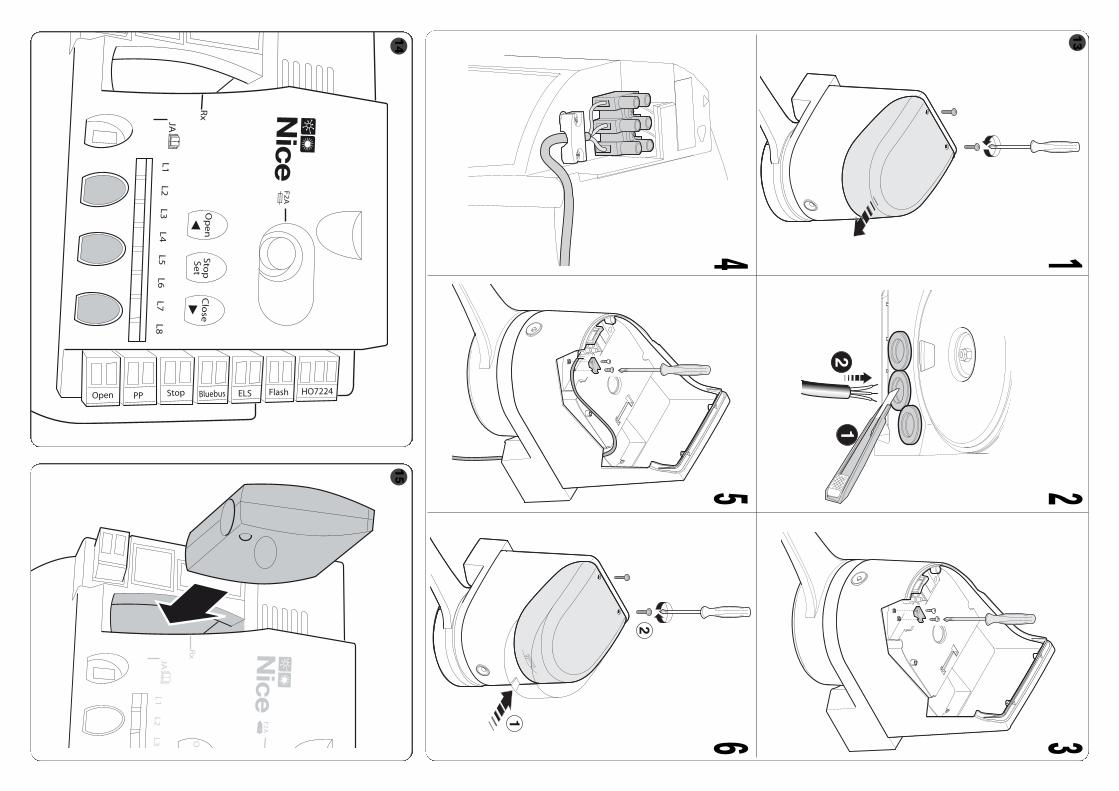
For more information on the Solemyo system, refer to the relative instructionmanual.To connect the Solemyo system, proceed as shown in fig. 19.8.5 - Connecting the external release system Kio
(fig. 20) CAUTION! – Kio must be connected to the gearmotor controlling the leafthat moves first (starting from the gate closed position).01. Remove the plastic cover (1);02. Insert pin (3) in the hole of the release shaft (2);03. Insert the steel cable (7) before the screw (4, then in the specific hole (5)
and then in the hole of pin (3);04. Hook up the spring (6) with the two ends positioned as shown in the figure;05. Secure the cable by tightening the relative screw (4);06. Route the other end of the cable through the hole on the lower section of
the gearmotor;07. Refit the plastic cover (1);08. At this point, connect the cable to Kio, with reference to the relative instruc-
tion manual.
8.3 - Connection of the Oview programmerThe control unit has a BusT4 connector to which the Oview programming unitcan be connect, and which allows the complete rapid management of the instal-lation and maintenance phase as well as the diagnosis of the entire automationsystem. To access this connector, proceed as shown in fig. 18 and connect theconnector to the dedicated seat. The Oview can be connected to several Con-trol units simultaneously (up to 5 without any particular precautions, and up to 60observing the dedicated warnings) and can stay connected to the control uniteven during the normal operation of the automation system. In this case, it canbe used to send the commands directly tot he control unit using the specific"user" menu. The Firmware upgrade can also be carried out. If there is a radioreceiver from the OXI family in the control unit, Oview can be used to gain accessto the parameters of the transmitters stored in the receiver itself.For further information, please consult the relevant instruction manual and themanual for the “Opera system book” system.8.4 - Connecting the solar power system Solemyo CAUTION! – When the automation is powered by the “Sole myo” system,IT MUST NEVER BE POWERED simultaneously by the electrical mains.
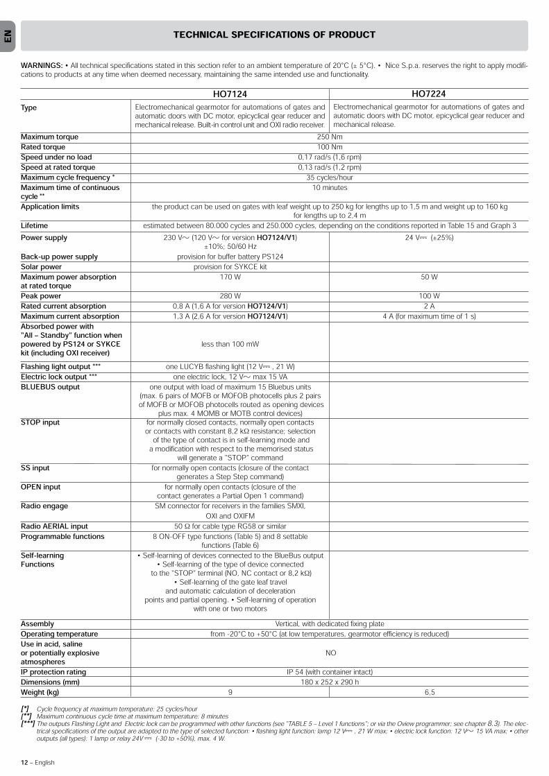
Type
Maximum torque 250 NmRated torque 100 NmSpeed under no load 0,17 rad/s (1,6 rpm)Speed at rated torque 0,13 rad/s (1,2 rpm)Maximum cycle frequency * 35 cycles/hourMaximum time of continuous 10 minutescycle **Application limits the product can be used on gates with leaf weight up to 250 kg for lengths up to 1,5 m and weight up to 160 kg
for lengths up to 2,4 mLifetime estimated between 80.000 cycles and 250.000 cycles, depending on the conditions reported in Table 15 and Graph 3
EN
12 – English
TECHNICAL SPECIFICATIONS OF PRODUCT
HO7224Electromechanical gearmotor for automations of gates andautomatic doors with DC motor, epicyclical gear reducer andmechanical release.
HO7124Electromechanical gearmotor for automations of gates andautomatic doors with DC motor, epicyclical gear reducer andmechanical release. Built-in control unit and OXI radio receiver.
Assembly Vertical, with dedicated fixing plateOperating temperature from -20°C to +50°C (at low temperatures, gearmotor efficiency is reduced)Use in acid, saline or potentially explosive NOatmospheresIP protection rating IP 54 (with container intact)Dimensions (mm) 180 x 252 x 290 hWeight (kg) 9 6,5[*] Cycle frequency at maximum temperature: 25 cycles/hour[**] Maximum continuous cycle time at maximum temperature: 8 minutes[***] The outputs Flashing Light and Electric lock can be programmed with other functions (see “TABLE 5 – Level 1 functions”; or via the Oview programmer; see chapter 8.3). The elec-
trical specifications of the output are adapted to the type of selected function: • flashing light function: lamp 12 V , 21 W max; • electric lock function: 12 V 15 VA max; • otheroutputs (all types): 1 lamp or relay 24V (-30 to +50%), max. 4 W.
Power supply 230 V (120 V for version HO7124/V1) 24 V (±25%)±10%; 50/60 Hz
Back-up power supply provision for buffer battery PS124Solar power provision for SYKCE kitMaximum power absorption 170 W 50 Wat rated torque Peak power 280 W 100 WRated current absorption 0,8 A (1,6 A for version HO7124/V1) 2 AMaximum current absorption 1,3 A (2,6 A for version HO7124/V1) 4 A (for maximum time of 1 s)Absorbed power with “All – Standby” function when powered by PS124 or SYKCE less than 100 mWkit (including OXI receiver)Flashing light output *** one LUCYB flashing light (12 V , 21 W)Electric lock output *** one electric lock, 12 V max 15 VABLUEBUS output one output with load of maximum 15 Bluebus units
(max. 6 pairs of MOFB or MOFOB photocells plus 2 pairsof MOFB or MOFOB photocells routed as opening devices
plus max. 4 MOMB or MOTB control devices)STOP input for normally closed contacts, normally open contacts
or contacts with constant 8,2 kΩ resistance; selectionof the type of contact is in self-learning mode and
a modification with respect to the memorised status will generate a “STOP” command
SS input for normally open contacts (closure of the contact generates a Step Step command)
OPEN input for normally open contacts (closure of the contact generates a Partial Open 1 command)
Radio engage SM connector for receivers in the families SMXI, OXI and OXIFM
Radio AERIAL input 50 Ω for cable type RG58 or similarProgrammable functions 8 ON-OFF type functions (Table 5) and 8 settable
functions (Table 6)Self-learning • Self-learning of devices connected to the BlueBus outputFunctions • Self-learning of the type of device connected
to the “STOP” terminal (NO, NC contact or 8,2 kΩ)• Self-learning of the gate leaf travel
and automatic calculation of deceleration points and partial opening. • Self-learning of operation
with one or two motors
WARNINGS: • All technical specifications stated in this section refer to an ambient temperature of 20°C (± 5°C). • Nice S.p.a. reserves the right to apply modifi-cations to products at any time when deemed necessary, maintaining the same intended use and functionality.

EN
English – 13
TABLE 15Severity index
< 1,0 m1,0 - 1,5 m1,5 - 2,4 m< 100 kg
100 - 150 kg150 - 250 kg
Leaf length
Leaf weight
Ambient temperature above 40°C or below 0°C or humidity over 80%Solid leafInstallation in windy zoneNote – The data refer to a balanced sectional door in perfect maintenance conditions
-15%20%
-20%30%20%15%15%
The lifetime is the average economic duration of the product. The value of lifeti-me is strongly influenced by the intensity of the manoeuvres performed by theautomation. i.e. the sum of all factors that contribute to product wear (see Table15).To establish the probable lifetime of your automation, proceed as follows:01. Calculate the severity index by adding all percentages of the items specifiedin Table 15;02. In Graph 3 from the value obtained above, trace vertical line until it inter-sects the curve; from this point trace a horizontal line until it intersects the lineof the “manoeuvre cycles”. The value obtained is the estimated lifetime of yourproduct.The estimation of lifetime is made on the basis of design calculations and theresults of tests performed on prototypes. As it is only an estimation, it does notrepresent any form of guarantee on the effective lifetime of the product.
Example of calculating the lifetime of a HOPP gearmotor (refer to Table 15and Graph 3):- leaf length = 1,3 m (severity index: 15%);- leaf weight: 180 Kg m (severity index: 30%);- solid leaf (severity index: 15%);Total severity index = 60%; Estimated lifetime = 100.000 manoeuvre cycles
50000
100000
150000
200000
250000
GRAPH 3
mano
euvre
cycle
s
Severity index %
PRODUCT LIFETIME

EN
14 – English
CE DECLARATION OF CONFORMITYand declaration of incorporation of “quasi machinery”
Declaration in accordance with the Directives: 2004/108/EC (EMC); 2006/42/EC (MD) appendix II, part B
Note - The contents of this declaration correspond to declarations in the official document deposited at the registered offices of Nice S.p.a. and in partic-ular to the last revision available before printing this manual. The text herein has been re-edited for editorial purposes.A copy of the original declaration can be requested from Nice S.p.a. (TV) I.
Declaration number: 376/HOPP Revision: 0 Language: EN
Manufacturer’s Name: NICE S.p.A.Address: Via Pezza Alta N° 13, 31046, Rustignè di Oderzo (TV) ItalyPerson authorised to draw up technical documentation: Mr. Oscar MarchettoAddress: Via Pezza Alta N° 13, 31046, Rustignè di Oderzo (TV) ItalyProduct type: "HOPP" Electromechanical gearmotor with built-in control unitModel / Type: HO7124, HO7224Accessories: SMXI, OXI, PS124, Oview
The undersigned, Luigi Paro, in the role of Managing Director, declares under his sole responsibility, that the product specified above con-forms to the provisions of the following directives:• DIRECTIVE 2004/108/EC OF THE EUROPEAN PARLIAMENT AND COUNCIL of 15 December 2004 regarding the approximation of
member state legislation related to electromagnetic compatibility, repealing directive 89/336/EEC, according to the following harmonizedstandards:EN 61000-6-2:2005, EN 61000-6-3:2007
The product also conforms to the following directive according to the requirements envisaged for “quasi machinery”:• Directive 2006/42/EC THE EUROPEAN PARLIAMENT AND COUNCIL of 17 May 2006 regarding machinery and which amends direc-
tive 95/16/EC (recasting)• It is hereby declared that the pertinent technical documentation has been compiled in compliance with appendix VII B of directive2006/42/EC and that the following essential requirements have been observed:1.1- 1.1.2- 1.1.3- 1.2.1-1.2.6- 1.5.1-1.5.2- 1.5.5- 1.5.6- 1.5.7- 1.5.8- 1.5.10- 1.5.11• The manufacturer undertakes to transmit to the national authorities, in response to a motivated request, all information regarding the“quasi-machine", while maintaining full rights to the related intellectual property. • Should the “quasi machine” be put into service in a European country with an official language other than that used in this declara-tion, the importer is obliged to arrange for the relative translation to accompany this declaration.• The “quasi-machine” must not be used until the final machine in which it is incorporated is in turn declared as compliant, if applica-ble, with the provisions of directive 2006/42/EC.
The product also complies with the following standards:EN 60335-1:2002 + A1:2004 + A11:2004 + A12:2006 + A2:2006 + A13:2008EN 60335-2-103:2003The product also complies, within the constraints of applicable parts, with the following standards:EN 13241-1:2003, EN 12445:2002, EN 12453:2002, EN 12978:2003
Oderzo, 24 January 2011
Ing. Luigi Paro (Managing Director)