TP soupapes - MarSuphydrosup.e-monsite.com/medias/files/tp-soupapes-2.pdf · sur 2T lent, descente...
15
1 FBP/AAG/FD ENSM LE HAVRE 2012/2013 TP SOUPAPES Objectifs : Visite d’une soupape à lanterne Méthode de rectification Rédaction d’un rapport de visite I. GENERALITES Le nombre de soupapes varie avec le type de moteur. Différents rôles : évacuer les gaz : soupape d’échappement introduire l’air de combustion : soupape d’admission admettre l’air de lancement : soupape d’air de lancement éviter les surpressions : soupape de sûreté ou de tarage Les différentes commandes : mécanique (par culbuterie) pneumatique (air de commande 7b) hydraulique (huile HP permet la fermeture de la soupape d’échappement sur 2T lent, descente commandée en pneumatique, exemple MAN B&W L90MC)
Transcript of TP soupapes - MarSuphydrosup.e-monsite.com/medias/files/tp-soupapes-2.pdf · sur 2T lent, descente...
1
FBP/AAG/FD ENSM LE HAVRE 2012/2013
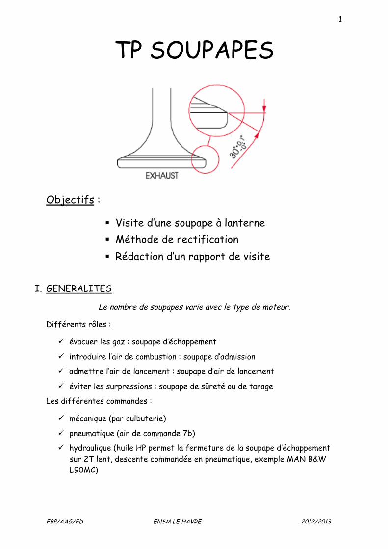
TP SOUPAPES
Objectifs :
Visite d’une soupape à lanterne Méthode de rectification Rédaction d’un rapport de visite
I. GENERALITES
Le nombre de soupapes varie avec le type de moteur.
Différents rôles :
évacuer les gaz : soupape d’échappement
introduire l’air de combustion : soupape d’admission
admettre l’air de lancement : soupape d’air de lancement
éviter les surpressions : soupape de sûreté ou de tarage
Les différentes commandes :
mécanique (par culbuterie)
pneumatique (air de commande 7b)
hydraulique (huile HP permet la fermeture de la soupape d’échappement sur 2T lent, descente commandée en pneumatique, exemple MAN B&W L90MC)
2
FBP/AAG/FD ENSM LE HAVRE 2012/2013
LES PARTICULARITES
Diamètre des soupapes d’admission supérieur à celui des soupapes d’échappement.
Les soupapes peuvent être à lanterne et/ou réfrigérées par eau ou huile.
A lanterne démontage par le dessus de la culasse (ex : PIELSTICK)
avec ou sans rotocap: si pourvue attention au remontage et contrôle du nombre de tours par minute de celui-ci à une allure donnée et constante
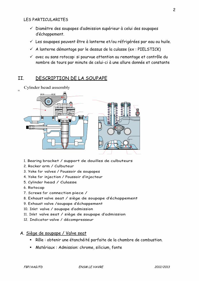
II. DESCRIPTION DE LA SOUPAPE
Cylinder head assembly III.
1. Bearing bracket / support de douilles de culbuteurs 2. Rocker arm / Culbuteur 3. Yoke for valves / Poussoir de soupapes 4. Yoke for injection / Poussoir d’injecteur 5. Cylinder head / Culasse 6. Rotocap 7. Screws for connection piece / 8. Exhaust valve seat / siège de soupape d’échappement 9. Exhaust valve /soupape d’échappement 10. Inlet valve / soupape d’admission 11. Inlet valve seat / siège de soupape d’admission 12. Indicator valve / décompresseur
A. Siège de soupape / Valve seat Rôle : obtenir une étanchéité parfaite de la chambre de combustion.
Matériaux : Admission: chrome, silicium, fonte
3
FBP/AAG/FD ENSM LE HAVRE 2012/2013
Echappement: acier spécial
Montage : usiné dans la masse ou rapporté sur la culasse.
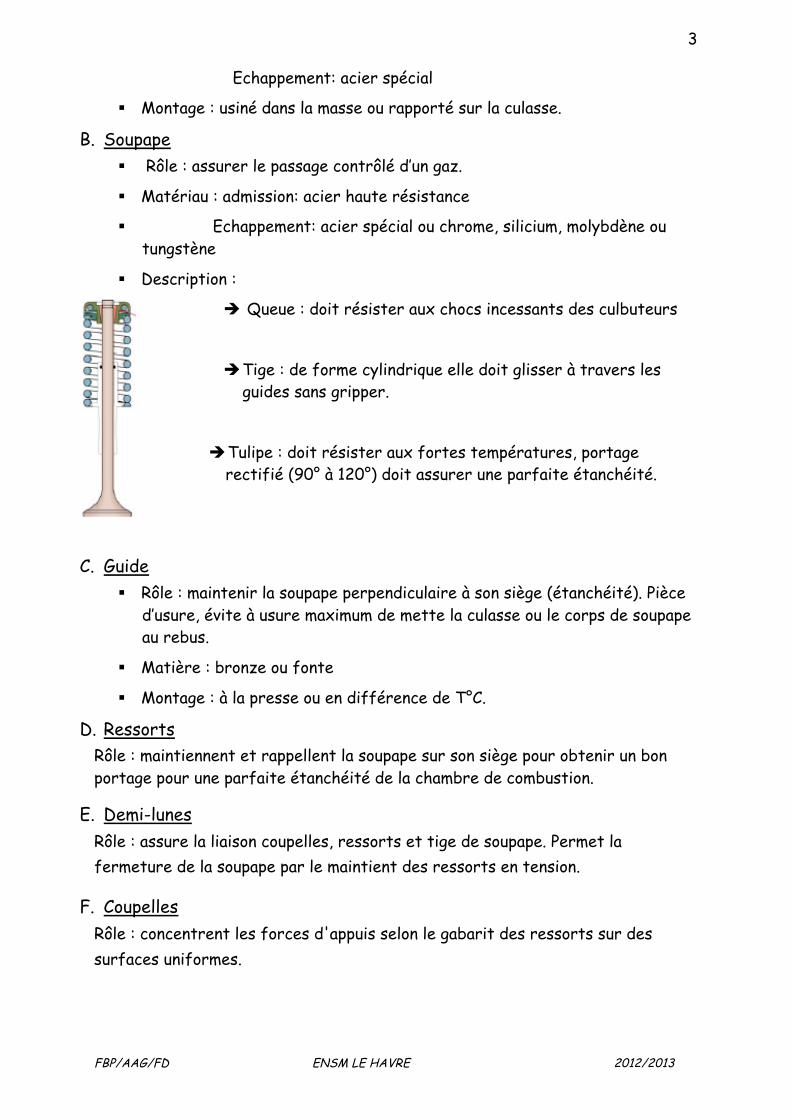
B. Soupape Rôle : assurer le passage contrôlé d’un gaz.
Matériau : admission: acier haute résistance
Echappement: acier spécial ou chrome, silicium, molybdène ou tungstène
Description :
Queue : doit résister aux chocs incessants des culbuteurs
Tige : de forme cylindrique elle doit glisser à travers les guides sans gripper.
Tulipe : doit résister aux fortes températures, portage rectifié (90° à 120°) doit assurer une parfaite étanchéité.
C. Guide Rôle : maintenir la soupape perpendiculaire à son siège (étanchéité). Pièce
d’usure, évite à usure maximum de mette la culasse ou le corps de soupape au rebus.
Matière : bronze ou fonte
Montage : à la presse ou en différence de T°C.
D. Ressorts Rôle : maintiennent et rappellent la soupape sur son siège pour obtenir un bon portage pour une parfaite étanchéité de la chambre de combustion.
E. Demi-lunes Rôle : assure la liaison coupelles, ressorts et tige de soupape. Permet la fermeture de la soupape par le maintient des ressorts en tension.
F. Coupelles Rôle : concentrent les forces d'appuis selon le gabarit des ressorts sur des surfaces uniformes.
4
FBP/AAG/FD ENSM LE HAVRE 2012/2013
Procédure générale
I. Visite selon guide constructeur :
Soupape : • nettoyage • inspection visuelle • ressuage • flambage de la tige au marbre • voile de la tulipe au marbre • épaisseur tulipe • diamètre de tige au niveau des guides de soupape. • contrôle de l’angle de la tête (pas de rodage car angles différents mais
rectification) • essai d’étanchéité sur son siège.(au DO)
Corps /siège:
• nettoyage des chambres à eau et détartrage, mécanique ou chimique (par bain à circulation)
• hauteur du siège de soupape, contrôle de l’angle • Epreuve (Essai d’étanchéité). • Cotation des guides de soupape.
Lanterne :
• nettoyage • Inspection visuelle
Ressort :
• inspection visuelle (comparer avec un neuf) longueur en charge/à vide • Intérêt d’un ressort interne et d’un ressort externe : répartition des
forces sur les coupelles, maintient le mouvement strictement vertical et annule le phénomène de résonnance
Manipulation des instruments de mesure à acquérir ou conforter
Micromètre intérieur 3pts Micromètre extérieur
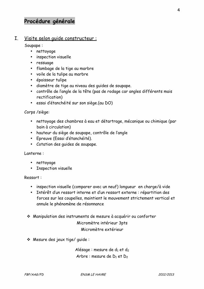
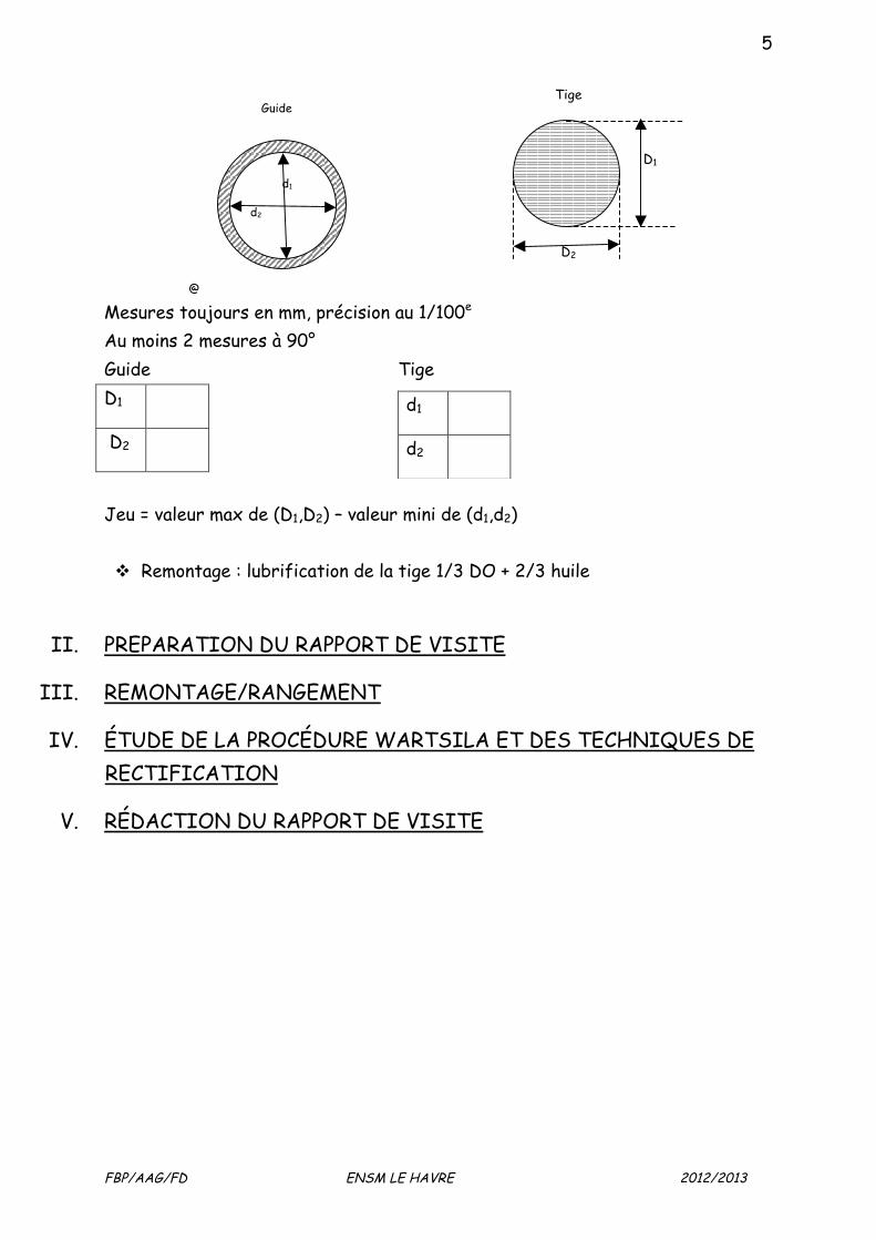
Mesure des jeux tige/ guide :
Alésage : mesure de d1 et d2 Arbre : mesure de D1 et D2
5
FBP/AAG/FD ENSM LE HAVRE 2012/2013
@ Mesures toujours en mm, précision au 1/100e Au moins 2 mesures à 90° Guide Tige D1
D2
Jeu = valeur max de (D1,D2) – valeur mini de (d1,d2) Remontage : lubrification de la tige 1/3 DO + 2/3 huile
II. PREPARATION DU RAPPORT DE VISITE
III. REMONTAGE/RANGEMENT
IV. ÉTUDE DE LA PROCÉDURE WARTSILA ET DES TECHNIQUES DE RECTIFICATION
V. RÉDACTION DU RAPPORT DE VISITE
d1
d2
d1
d2
Guide
D1
D2
Tige
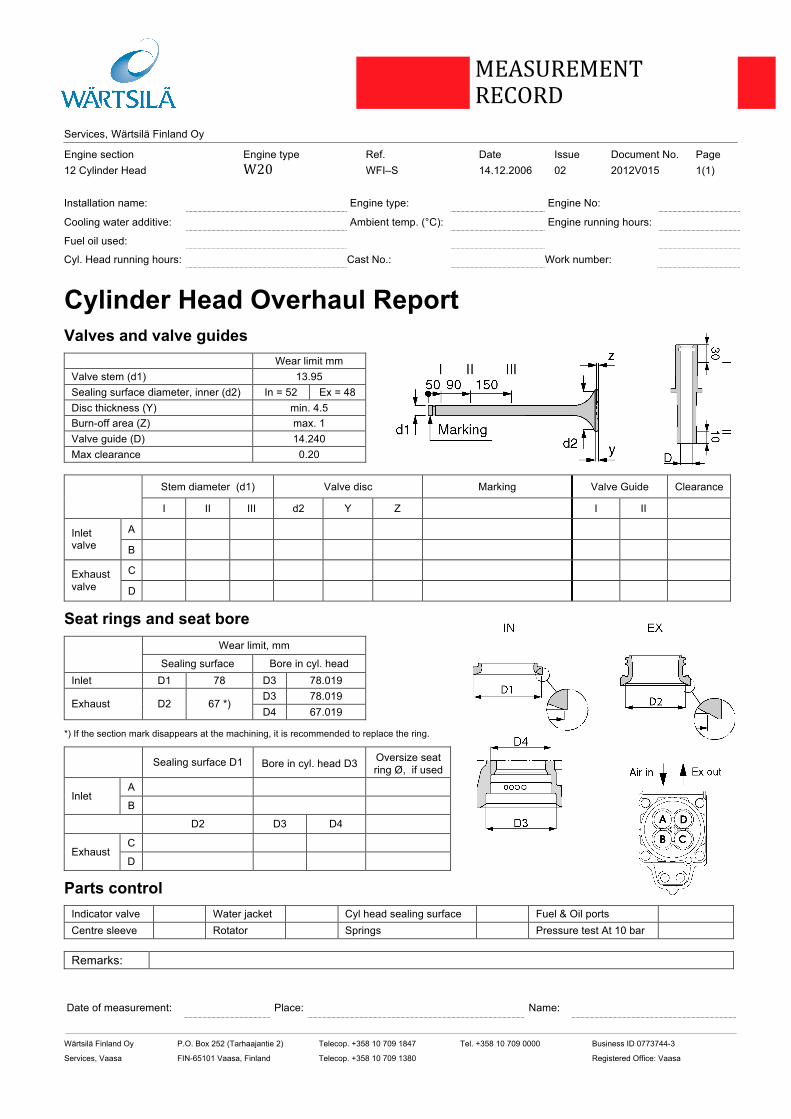
Services, Wärtsilä Finland Oy
Engine section Engine type Ref. Date Issue Document No. Page 12 Cylinder Head W20 WFI–S 14.12.2006 02 2012V015 1(1)
Wärtsilä Finland Oy P.O. Box 252 (Tarhaajantie 2) Telecop. +358 10 709 1847 Tel. +358 10 709 0000 Business ID 0773744-3
Services, Vaasa FIN-65101 Vaasa, Finland Telecop. +358 10 709 1380 Registered Office: Vaasa
Wärtsilä Finland Oy P.O. Box 50 (Stålarminkatu 45) Telecop. +358 10 709 3279 Tel. +358 10 709 0000
Services, Turku FIN-20811 Turku, Finland Telecop. +358 10 709 3410
MEASUREMENT RECORD
Installation name:
Engine type:
Engine No:
Cooling water additive:
Ambient temp. (°C):
Engine running hours:
Fuel oil used:
Cyl. Head running hours:
Cast No.:
Work number:
Cylinder Head Overhaul Report Valves and valve guides
Wear limit mm Valve stem (d1) 13.95 Sealing surface diameter, inner (d2) In = 52 Ex = 48 Disc thickness (Y) min. 4.5 Burn-off area (Z) max. 1 Valve guide (D) 14.240 Max clearance 0.20
Stem diameter (d1) Valve disc Marking Valve Guide Clearance
I II III d2 Y Z I II
A
Inlet valve B
C
Exhaust valve D
Seat rings and seat bore Wear limit, mm
Sealing surface Bore in cyl. head
Inlet D1 78 D3 78.019 D3 78.019
Exhaust D2 67 *) D4 67.019
*) If the section mark disappears at the machining, it is recommended to replace the ring.
Sealing surface D1 Bore in cyl. head D3 Oversize seat ring Ø, if used
A
Inlet
B
D2 D3 D4
C
Exhaust
D
Parts control Indicator valve
Water jacket
Cyl head sealing surface
Fuel & Oil ports
Centre sleeve
Rotator
Springs
Pressure test At 10 bar
Remarks:
Date of measurement:
Place:
Name:
CONFIDENTIE
L
5 Put a feeler gauge corresponding to the valve clearancebetween the surface of the yoke and the shoe at the rocker arm.Tighten the adjusting screw (1) until the feeler gauge can bemoved to and fro only with slight force. Hold the adjustingscrew and tighten the counter nut. Check that the clearancehas not changed while tightening.
12.3 Exhaust and inlet valves and seat rings
12.3.1 General description
Data and dimensionsMaterial: High quality steelDiameter-inlet valve: 73 mm-exhaust valve: 66 mm
Valve seat ringMaterial: High quality steelAngle-inlet seat: 20°-exhaust seat: 30°
The cylinder head has four valves fitted, two inlet valves and twoexhaust valves. All the valves are made of surface-treated heatresistant steel. The inlet valves are bigger than the exhaustvalves. The valves move in cast iron guides, which are press fitted inthe cylinder head and can be replaced. The valve guides have anO-ring (sealing against the valve stem), which is located at thetop of the guide bore. The valves are provided with one valve spring per valve andvalve rotating devices or valve spring retainers. Valve seat ring is fitted in the cylinder head for both inlet andexhaust valves. The exhaust valve seat rings are cooled and henceprovided with one or two O-rings seat.
12.3.2 Dismantling valves
1 Fit the tool 846010 according to Fig 12-4.
Tool assembly for dismantling valves
A. Fastening screwA
Fig 12-4 2012529312
12 Cylinder Head with Valves 20-200637-01
12 - 6 WÄRTSILÄ 20
CONFIDENTIE
L
2 Compress the springs about 15-20 mm by the screw.
3 Knock at the centre of the valve discs with a soft pieceof wood, plastic hammer or similar, whereby the valve cotterscome loose and can be removed.
4 Unload the tool.
5 Spring retainers and springs can now be removed.
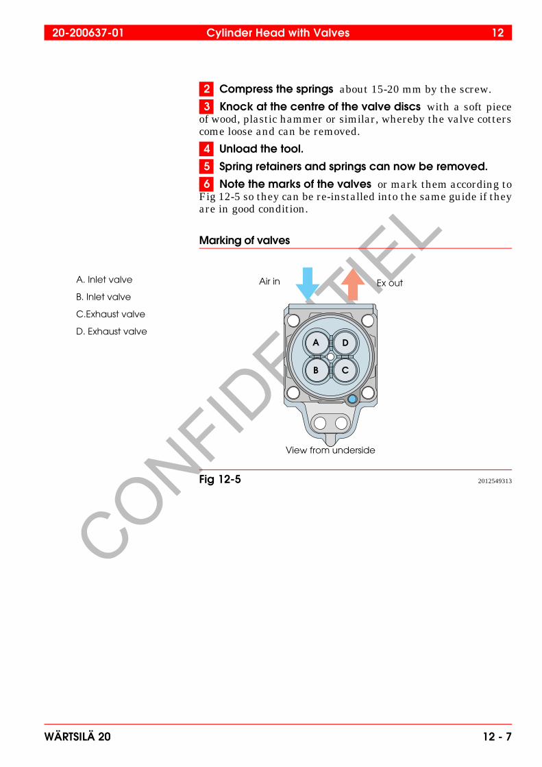
6 Note the marks of the valves or mark them according toFig 12-5 so they can be re-installed into the same guide if theyare in good condition.
Marking of valves
A D
CB
Ex outAir inA. Inlet valve
B. Inlet valve
C.Exhaust valve
D. Exhaust valve
View from underside
Fig 12-5 2012549313
20-200637-01 Cylinder Head with Valves 12
WÄRTSILÄ 20 12 - 7
CONFIDENTIE
L
12.3.3 Checking and reconditioning of valves and seats
1 Clean the valves, seats, ducts and guides as well as theunderside of the cylinder head.
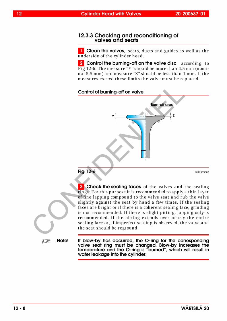
2 Control the burning-off on the valve disc according toFig 12-6. The measure “Y” should be more than 4.5 mm (nomi-nal 5.5 mm) and measure “Z” should be less than 1 mm. If themeasures exceed these limits the valve must be replaced.
Control of burning-off on valve
3 Check the sealing faces of the valves and the sealingrings. For this purpose it is recommended to apply a thin layerof fine lapping compound to the valve seat and rub the valveslightly against the seat by hand a few times. If the sealingfaces are bright or if there is a coherent sealing face, grindingis not recommended. If there is slight pitting, lapping only isrecommended. If the pitting extends over nearly the entiresealing face or, if imperfect sealing is observed, the valve andthe seat should be reground.
Note! If blow-by has occurred, the O-ring for the correspondingvalve seat ring must be changed. Blow-by increases thetemperature and the O-ring is “burned”, which will result inwater leakage into the cylinder.
ZY
Burn-off area
Fig 12-6 2012569805
12 Cylinder Head with Valves 20-200637-01
12 - 8 WÄRTSILÄ 20
CONFIDENTIE
L
4 Before grinding, check the valve stem clearance. Ifthe clearance is too large, measure the stem and guide, andchange the worn part; the valve guide can be pressed out.Check the bore in the cylinder head. When refitting, cooling inwith liquid nitrogen is recommended, but pressing in with oillubrication can also be accepted. After fitting in, check theguide bore and calibrate, if necessary.
12.3.4 Lapping
If there are slight pits on the sealing faces they can be lapped byhand:
1 Fit the turning tool to the valve.
2 Apply a thin layer of lapping compound to the sealingsurface of the valve; No.1 for coarse lapping, No.3 for finelapping.
3 Rotate the valve to and fro towards the seat with theturning tool 841001. Lift the valve from the seat at intervalswhile lapping.
4 Remove the smallest possible amount of material because the sealing faces have hardened during operation andare valuable. It is not necessary to grind off all pits.
5 Clean the valve and seat carefully after lapping.
12.3.5 Machine grinding
If there is deep pitting or other damage, the valve and seat shouldbe ground by machine.
Note! The valve should be cooled by water during the grinding.
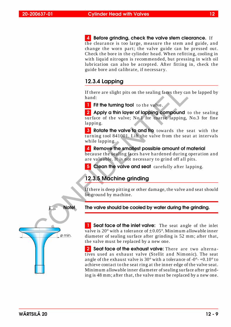
1 Seat face of the inlet valve: The seat angle of the inletvalve is 20° with a tolerance of ± 0.05°. Minimum allowable innerdiameter of sealing surface after grinding is 52 mm; after that,the valve must be replaced by a new one.
2 Seat face of the exhaust valve: There are two alterna-tives used as exhaust valve (Stellit and Nimonic). The seatangle of the exhaust valve is 30° with a tolerance of -0°- +0.10° toachieve contact to the seat ring at the inner edge of the valve seat.Minimum allowable inner diameter of sealing surface after grind-ing is 48 mm; after that, the valve must be replaced by a new one.
ø min.
20-200637-01 Cylinder Head with Valves 12
WÄRTSILÄ 20 12 - 9
CONFIDENTIE
L
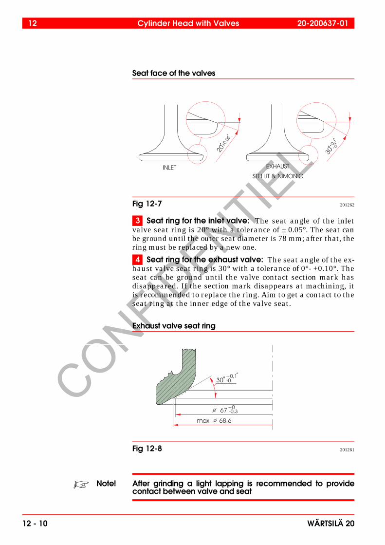
Seat face of the valves
3 Seat ring for the inlet valve: The seat angle of the inletvalve seat ring is 20° with a tolerance of ± 0.05°. The seat canbe ground until the outer seat diameter is 78 mm; after that, thering must be replaced by a new one.
4 Seat ring for the exhaust valve: The seat angle of the ex-haust valve seat ring is 30° with a tolerance of 0°- +0.10°. Theseat can be ground until the valve contact section mark hasdisappeared. If the section mark disappears at machining, itis recommended to replace the ring. Aim to get a contact to theseat ring at the inner edge of the valve seat.
Exhaust valve seat ring
Note! After grinding a light lapping is recommended to providecontact between valve and seat
Fig 12-7 201262
Fig 12-8 201261
12 Cylinder Head with Valves 20-200637-01
12 - 10 WÄRTSILÄ 20
CONFIDENTIE
L
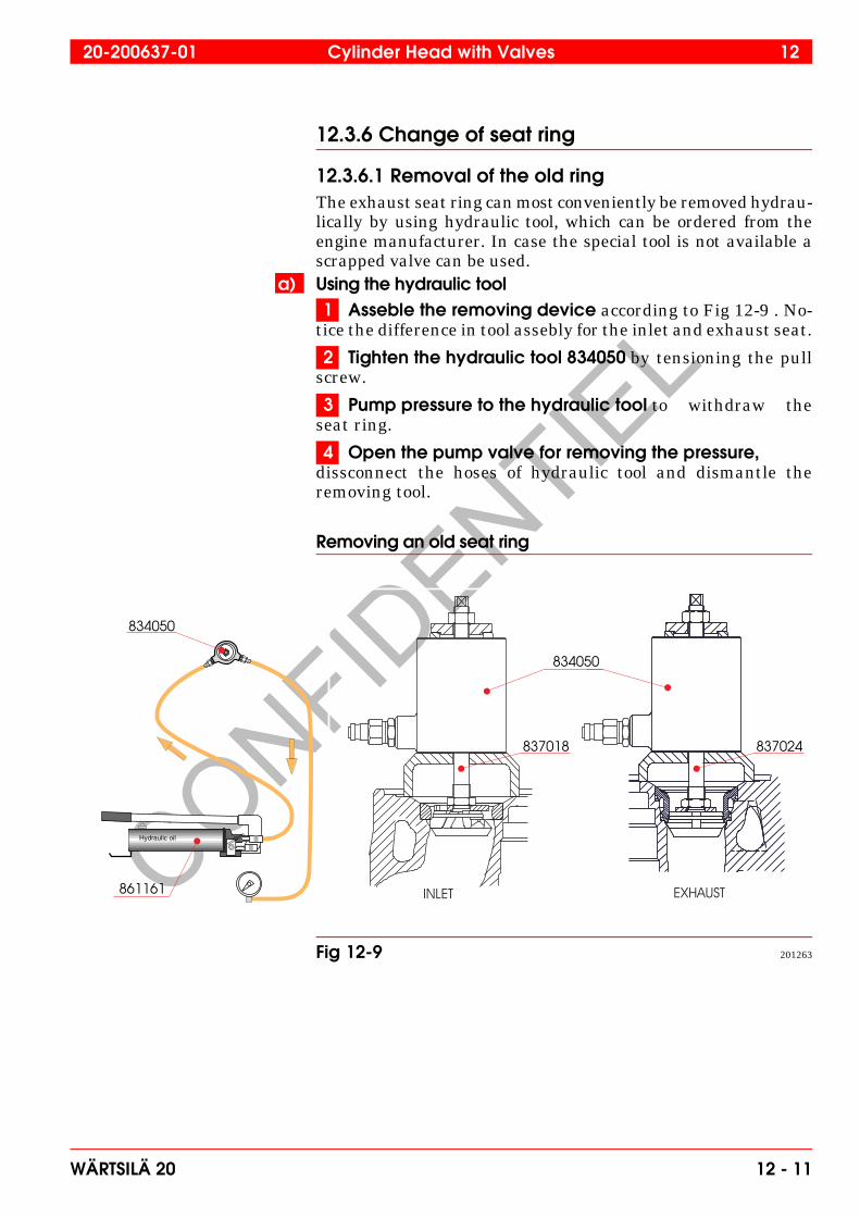
12.3.6 Change of seat ring
12.3.6.1 Removal of the old ringThe exhaust seat ring can most conveniently be removed hydrau-lically by using hydraulic tool, which can be ordered from theengine manufacturer. In case the special tool is not available ascrapped valve can be used.
a) Using the hydraulic tool1 Asseble the removing device according to Fig 12-9 . No-
tice the difference in tool assebly for the inlet and exhaust seat.
2 Tighten the hydraulic tool 834050 by tensioning the pullscrew.
3 Pump pressure to the hydraulic tool to withdraw theseat ring.
4 Open the pump valve for removing the pressure,dissconnect the hoses of hydraulic tool and dismantle theremoving tool.
Removing an old seat ring
Hydraulic oil
834050
837024
834050
837018
861161
Fig 12-9 201263
20-200637-01 Cylinder Head with Valves 12
WÄRTSILÄ 20 12 - 11
CONFIDENTIE
L
b) Using the scrapped valve1 Fit a scrapped valve to the seat and weld it to the seat
by means of electric beam welding. Preferably the valve discshould be machined to a diameter 55-60 mm to get a betterwelding.
Note! Protect flame plate and cylinder head gasket sealing surfacein the case of welding.
2 Press or knock out the ring but be careful not to damagethe valve guide.
12.3.6.2 Fitting a new inlet valve seat ring1 Check the bore diameter in the cylinder head, see sec-
tion 06.2.
2 The inlet seat ring can be assembled by freezing in liq-uid nitrogen of -190°C, the cylinder head temperature beingmin. 20°C, or if isn’t possible to use liquid nitrogen. Other wayby using freezer, the temperature difference has to be mini-mum 120°C.
3 Check the eccentricity of the sealing face in relation tothe valve guide, and if it exceeds 0.1 mm, the seat surface mustbe ground in a seat grinding machine.
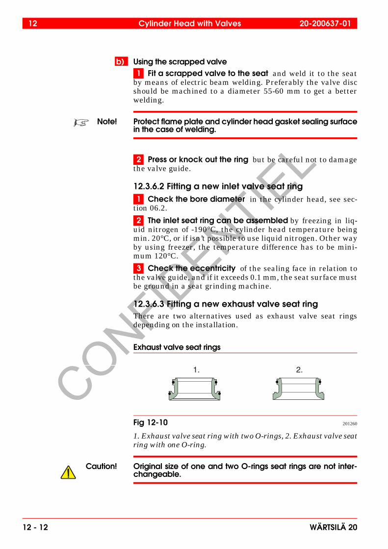
12.3.6.3 Fitting a new exhaust valve seat ringThere are two alternatives used as exhaust valve seat ringsdepending on the installation.
Exhaust valve seat rings
1. Exhaust valve seat ring with two O-rings, 2. Exhaust valve seatring with one O-ring.
Caution! Original size of one and two O-rings seat rings are not inter-changeable.
1. 2.
Fig 12-10 201260
12 Cylinder Head with Valves 20-200637-01
12 - 12 WÄRTSILÄ 20
CONFIDENTIE
L
1 Clean the bore carefully with a grit 400 or finer emerycloth.
2 Check the bore diameter in the cylinder head, see sec-tion 06.2 in this manual.
3 Cool the seat ring to -20 - -25°C prior to fitting. Note thata temperature lower than -25°C may damage the O-ring(s) atmounting.
4 Heat up the entire cylinder head to 100°C by means ofeither steam heating, e.g. put the cylinder head into a closedbox, or a gas burner.
Note! It is important that the entire cylinder head is heated up, notonly the seat bore.
5 Mount the O-ring(s) on the cooled valve seat.
6 Apply soap-water solution to lubricate the O-ring(s).
7 If mounting the exhaust valve seat ring with one O-ring.• Clean with Loctite 7063.• Apply Loctite 620 to the cylinder head. Loctite only to be used
on large (∅ 78) diameter without O-ring. Not O-ring area.For more information of use of Loctite, see section 12.3.7 8 Mount the exhaust valve seat by using one of following
methods:• Put the seat rings into a guiding bush and press in the seat
with a guided arbor. A special tool 837032 is also available.This tool can be ordered from the engine manufacturer.
• Insert the seat ring by using an old scrapped exhaust valve.Don’t use exhaust valve which is to be reused! Knock/pushon the valve until the seat ring is correctly seated.
Note! It’s recommended to replace the exhaust seat ring O-ringsevery time when overhaul.
Note! Mounting of a exhaust valve seat ring should be done carefullyso that the seat ring is correctly seated.
9 Check the eccentricity of the sealing face in relationto the valve guide, and if it exceeds 0.1 mm, the seat surfaceshould be ground in a seat grinding machine.
20-200637-01 Cylinder Head with Valves 12
WÄRTSILÄ 20 12 - 13
CONFIDENTIE
L
10 Pressure test the cylinder head water side beforemounting with a test pressure of 10 bar if possible.Use pres-sure test tool (847 004 and 847 005) for blocking the water holesof cylinder head.
12.3.7 Use of Loctite products for locking the seatsand centre sleeves
1 After the "hot" cylinder head washing the seat pocketsis to be cleaned with hot water and/or a wet cloth to removepossible anti-corrosion chemicals from the pocket surface toachieve a pH value close to pH7
2 Loctite 7063 cleaner is to be used on a cooled seat priorassembly to remove possible frost, dirt from the seat surfaceand remove possible protection chemicals. Neutralises thesurface close to pH7.
Note! Power cleaner or similar should not to be used.
3 Apply the 620 on the surface, which is to be locked witha seat or sleeve. Loctite 620 is to be use because of the hightemperature performance. Loctite 620 need a 1 hours curingtime.
Note! Do not apply Loctite on an O-ring (use soap-water solution)!
12.3.8 Reassembling of the engine valves
1 Check the valve springs for cracks, corrosion or wearmarks, and if any, replace the springs by new ones.
2 Put new seal rings in the valve guides.
3 Lubricate the valve stems with engine oil.
4 Put in the valves and check for free movement.
5 Put on the springs and rotators. Replace the valve rota-tors if they are worn or damaged.
6 Compress the springs with the tool set.
7 Put in the valve cotters and unload the springs.
8 Check that the valve cotters fit properly.
9 Check function of the valve rotators by putting a markfor instance by using a felt pen on the valve disc and a corre-sponding mark on the cylinder head. Hit gently on the valvestem by using a non-recoiling hammer to check the rotation.
12 Cylinder Head with Valves 20-200637-01
12 - 14 WÄRTSILÄ 20