Textile-reinforced mortar (TRM) versus fibre-reinforced...
13
Textile-reinforced mortar (TRM) versus fibre-reinforced polymers (FRP) in flexural strengthening of RC beams Saad M. Raoof a,b,⇑ , Lampros N. Koutas c , Dionysios A. Bournas d a Department of Civil Engineering, University of Nottingham, NG7 2RD Nottingham, UK b Department of Civil Engineering, University of Tikrit, Tikrit, Iraq c Department of Civil and Structural Engineering, University of Sheffield, S1 3JD Sheffield, UK d European Commission, Joint Research Centre (JRC), Directorate for Space, Security and Migration, Safety and Security of Buildings Unit, via E. Fermi 2749, I-21027 Ispra, Italy highlights TRM was compared to FRP in flexural strengthening of RC beams. TRM was almost as effective as FRP when debonding governed the failure. Effectiveness of TRM versus FRP was improved by increasing the number of layers. Epoxy coated textiles resulted in increased efficiency of TRM system. TRM debonding stress was predicted using a formula developed for FRP systems. article info Article history: Received 21 January 2017 Received in revised form 19 April 2017 Accepted 5 May 2017 Keywords: Basalt fibres Carbon fibres Flexure Glass fibres Reinforced concrete Strengthening Textile reinforced mortar TRM abstract This paper compares the flexural performance of reinforced concrete (RC) beams strengthened with textile-reinforced mortar (TRM) and fibre-reinforced polymers (FRP). The investigated parameters included the strengthening material, namely TRM or FRP; the number of TRM/FRP layers; the textile sur- face condition (coated and uncoated); the textile fibre material (carbon, coated basalt or glass fibres); and the end-anchorage system of the external reinforcement. Thirteen RC beams were fabricated, strength- ened and tested in four-point bending. One beam served as control specimen, seven beams strengthened with TRM, and five with FRP. It was mainly found that: (a) TRM was generally inferior to FRP in enhancing the flexural capacity of RC beams, with the effectiveness ratio between the two systems varying from 0.46 to 0.80, depending on the parameters examined, (b) by tripling the number of TRM layers (from one to three), the TRM versus FRP effectiveness ratio was almost doubled, (c) providing coating to the dry textile enhanced the TRM effectiveness and altered the failure mode; (d) different textile materials, having approximately same axial stiffness, resulted in different flexural capacity increases; and (e) providing end-anchorage had a limited effect on the performance of TRM-retrofitted beams. Finally, a simple for- mula proposed by fib Model Code 2010 for FRP reinforcement was used to predict the mean debonding stress developed in the TRM reinforcement. It was found that this formula is in a good agreement with the average stress calculated based on the experimental results when failure was similar to FRP- strengthened beams. Ó 2017 The Authors. Published by Elsevier Ltd. This is an open access article under the CC BY license (http:// creativecommons.org/licenses/by/4.0/). 1. Introduction and background Over the last decades, the issue of upgrading and structural strengthening the existing reinforced concrete (RC) infrastructure has become of great importance. This is due to deterioration of these structures as a result of ageing, environmental conditions, lack of maintenance, and the need to meet the current design codes requirements (i.e. Eurocodes). Over the last two decades, the use fibre-reinforced polymers (FRP) for retrofitting concrete structures, has gain popularity among other conventional strengthening sys- tems (such as steel/RC jacketing). However, some drawbacks have been observed with the use of FRPs, which are mainly associated to the use of epoxy resins. These drawbacks include high cost, inabil- ity to apply on wet surfaces or at low ambient temperature, low http://dx.doi.org/10.1016/j.conbuildmat.2017.05.023 0950-0618/Ó 2017 The Authors. Published by Elsevier Ltd. This is an open access article under the CC BY license (http://creativecommons.org/licenses/by/4.0/). ⇑ Corresponding author at: Department of Civil Engineering, University of Nottingham, NG7 2RD Nottingham, UK. E-mail addresses: [email protected] (S.M. Raoof), L.Koutas@ sheffield.ac.uk (L.N. Koutas), [email protected] (D.A. Bournas). Construction and Building Materials 151 (2017) 279–291 Contents lists available at ScienceDirect Construction and Building Materials journal homepage: www.elsevier.com/locate/conbuildmat
Transcript of Textile-reinforced mortar (TRM) versus fibre-reinforced...
Construction and Building Materials 151 (2017) 279–291
Contents lists available at ScienceDirect
Construction and Building Materials
journal homepage: www.elsevier .com/locate /conbui ldmat
Textile-reinforced mortar (TRM) versus fibre-reinforced polymers (FRP)in flexural strengthening of RC beams
http://dx.doi.org/10.1016/j.conbuildmat.2017.05.0230950-0618/� 2017 The Authors. Published by Elsevier Ltd.This is an open access article under the CC BY license (http://creativecommons.org/licenses/by/4.0/).
⇑ Corresponding author at: Department of Civil Engineering, University ofNottingham, NG7 2RD Nottingham, UK.
E-mail addresses: [email protected] (S.M. Raoof), [email protected] (L.N. Koutas), [email protected] (D.A. Bournas).
Saad M. Raoof a,b,⇑, Lampros N. Koutas c, Dionysios A. Bournas d
aDepartment of Civil Engineering, University of Nottingham, NG7 2RD Nottingham, UKbDepartment of Civil Engineering, University of Tikrit, Tikrit, IraqcDepartment of Civil and Structural Engineering, University of Sheffield, S1 3JD Sheffield, UKd European Commission, Joint Research Centre (JRC), Directorate for Space, Security and Migration, Safety and Security of Buildings Unit, via E. Fermi 2749, I-21027 Ispra, Italy
h i g h l i g h t s
� TRM was compared to FRP in flexural strengthening of RC beams.� TRM was almost as effective as FRP when debonding governed the failure.� Effectiveness of TRM versus FRP was improved by increasing the number of layers.� Epoxy coated textiles resulted in increased efficiency of TRM system.� TRM debonding stress was predicted using a formula developed for FRP systems.
a r t i c l e i n f o
Article history:Received 21 January 2017Received in revised form 19 April 2017Accepted 5 May 2017
Keywords:Basalt fibresCarbon fibresFlexureGlass fibresReinforced concreteStrengtheningTextile reinforced mortarTRM
a b s t r a c t
This paper compares the flexural performance of reinforced concrete (RC) beams strengthened withtextile-reinforced mortar (TRM) and fibre-reinforced polymers (FRP). The investigated parametersincluded the strengthening material, namely TRM or FRP; the number of TRM/FRP layers; the textile sur-face condition (coated and uncoated); the textile fibre material (carbon, coated basalt or glass fibres); andthe end-anchorage system of the external reinforcement. Thirteen RC beams were fabricated, strength-ened and tested in four-point bending. One beam served as control specimen, seven beams strengthenedwith TRM, and five with FRP. It was mainly found that: (a) TRMwas generally inferior to FRP in enhancingthe flexural capacity of RC beams, with the effectiveness ratio between the two systems varying from 0.46to 0.80, depending on the parameters examined, (b) by tripling the number of TRM layers (from one tothree), the TRM versus FRP effectiveness ratio was almost doubled, (c) providing coating to the dry textileenhanced the TRM effectiveness and altered the failure mode; (d) different textile materials, havingapproximately same axial stiffness, resulted in different flexural capacity increases; and (e) providingend-anchorage had a limited effect on the performance of TRM-retrofitted beams. Finally, a simple for-mula proposed by fib Model Code 2010 for FRP reinforcement was used to predict the mean debondingstress developed in the TRM reinforcement. It was found that this formula is in a good agreement withthe average stress calculated based on the experimental results when failure was similar to FRP-strengthened beams.� 2017 The Authors. Published by Elsevier Ltd. This is an openaccess article under the CCBY license (http://
creativecommons.org/licenses/by/4.0/).
1. Introduction and background
Over the last decades, the issue of upgrading and structuralstrengthening the existing reinforced concrete (RC) infrastructurehas become of great importance. This is due to deterioration of
these structures as a result of ageing, environmental conditions,lack of maintenance, and the need to meet the current design codesrequirements (i.e. Eurocodes). Over the last two decades, the usefibre-reinforced polymers (FRP) for retrofitting concrete structures,has gain popularity among other conventional strengthening sys-tems (such as steel/RC jacketing). However, some drawbacks havebeen observed with the use of FRPs, which are mainly associated tothe use of epoxy resins. These drawbacks include high cost, inabil-ity to apply on wet surfaces or at low ambient temperature, low
280 S.M. Raoof et al. / Construction and Building Materials 151 (2017) 279–291
permeability to water vapour, and poor behaviour at hightemperatures.
To overcome these drawbacks, a new alternative cement-basedcomposite material, known as textile-reinforced mortar (TRM), hasbeen suggested for external strengthening of structures [1,2]. ATRM is a composite comprises high-strength fibres made of carbon,basalt or glass in form of textiles embedded into inorganic materi-als such as cement-based mortars. The textiles typically consist offibre rovings woven or stitched at least in two orthogonal direc-tions, thus creating an open-mesh geometry. TRM composite isalso identified with other acronyms such as TRC [3], and FRCM[4]. Several advantages of TRM are associated with the use ofcement-based mortars including: resistance to high temperatures[5,6], low cost, ability to be applied in an environment of low tem-peratures or on a wet surface, permeability to water vapour, andcompatibility with concrete substrates.
In the last few years, a significant number of studies have beendirected towards investigating possible exploitation of TRM in sev-eral cases of retrofitting RC structural elements. Bond betweenTRM and concrete substrate has been investigated in many studies[7–14]. TRM jacketing has also been applied as a mean of externalstrengthening of RC structures in the following cases: confinementof RC columns (i.e. [1]), shear retrofitting of RC elements [2,15–19],confinement of RC columns subjected to seismic load (e.g. [20–24]), reinforcing of infilled RC frames subjected to seismic load[25], flexural strengthening of one-way (e.g. [26–28]) and two-way [29] RC slabs. The results indicated that TRM is a promisingalternative to FRP in retrofitting structures. Examples of real appli-cations of TRM worldwide in the construction field can be found in[30].
Research on the flexural performance of RC beams strengthenedwith TRM has been reported in [31–37]. Parameters investigated inthese studies, were; the textile-fibre materials, for example,carbon-fibre textiles in [31,33,37], polyparaphenylene benzobisox-azole (PBO)-fibre textiles in [32–34,37], and basalt-fibre textile[35]; the number of layers [32–37]; the strengthening configura-tion [33]; the compressive strength of concrete [36]; and the typeof textile-fibre materials [37]. The main conclusions of these stud-ies were: (a) application of TRM to RC beams considerablyimproved their flexural capacity [31–37]; (b) increasing the num-ber of TRM layers had twofold effect: increased the flexural capac-ity and altered the failure mode [32,37].
The comparison between TRM and FRP strengthening system inenhancing the flexural capacity of RC beams has been onlyreported in a few number of studies. In the study of Triantafillouand Papanicolaou, 2005 [31] it was found, on the basis of onlytwo specimens, that TRM was 30% less effective than FRP, withthe observed failure mode being different (rupture of fibres forthe FRP-strengthened beam and interlaminar debonding for theTRM-strengthened beam). Elsanadedy et al., 2013 [35] reportedthat, the performance of TRM strengthening system in enhancingthe flexural capacity of RC beams was slightly less than that forFRP system. But TRM system is more efficient in increasing the
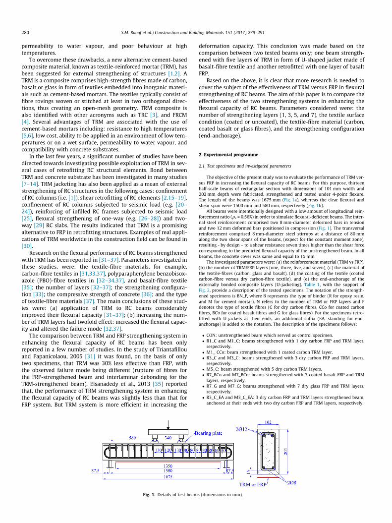
Fig. 1. Details of test beam
deformation capacity. This conclusion was made based on thecomparison between two tested beams only; one beam strength-ened with five layers of TRM in form of U-shaped jacket made ofbasalt-fibre textile and another retrofitted with one layer of basaltFRP.
Based on the above, it is clear that more research is needed tocover the subject of the effectiveness of TRM versus FRP in flexuralstrengthening of RC beams. The aim of this paper is to compare theeffectiveness of the two strengthening systems in enhancing theflexural capacity of RC beams. Parameters considered were: thenumber of strengthening layers (1, 3, 5, and 7), the textile surfacecondition (coated or uncoated), the textile-fibre material (carbon,coated basalt or glass fibres), and the strengthening configuration(end-anchorage).
2. Experimental programme
2.1. Test specimens and investigated parameters
The objective of the present study was to evaluate the performance of TRM ver-sus FRP in increasing the flexural capacity of RC beams. For this purpose, thirteenhalf-scale beams of rectangular section with dimensions of 101 mm width and202 mm depth were fabricated, strengthened and tested under 4-point flexure.The length of the beams was 1675 mm (Fig. 1a), whereas the clear flexural andshear span were 1500 mm and 580 mm, respectively (Fig. 1b).
All beams were intentionally designed with a low amount of longitudinal rein-forcement ratio (qs = 0.56%) in order to simulate flexural-deficient beams. The inter-nal steel reinforcement comprised two 8 mm-diameter deformed bars in tensionand two 12 mm deformed bars positioned in compression (Fig. 1). The transversalreinforcement comprised 8 mm-diameter steel stirrups at a distance of 80 mmalong the two shear spans of the beams, (expect for the constant moment zone),resulting - by design – to a shear resistance seven times higher than the shear forcecorresponding to the predicted flexural capacity of the unstrengthened beam. In allbeams, the concrete cover was same and equal to 15 mm.
The investigated parameters were: (a) the reinforcement material (TRM vs FRP),(b) the number of TRM/FRP layers (one, three, five, and seven), (c) the material ofthe textile-fibres (carbon, glass and basalt), (d) the coating of the textile (coatedcarbon-fibre versus dry carbon-fibre textile), and (e) the end-anchorage of theexternally bonded composite layers (U-jacketing). Table 1, with the support ofFig. 2, provide a description of the tested specimens. The notation of the strength-ened specimens is BN_F, where B represents the type of binder (R for epoxy resin,and M for cement mortar), N refers to the number of TRM or FRP layers and Fdenotes the type of textile fibres (C for dry carbon fibres, CCo for coated carbonfibres, BCo for coated basalt fibres and G for glass fibres). For the specimens retro-fitted with U-jackets at their ends, an additional suffix (EA, standing for end-anchorage) is added to the notation. The description of the specimens follows:
� CON: unstrengthened beam which served as control specimen.� R1_C and M1_C: beams strengthened with 1 dry carbon FRP and TRM layer,respectively.
� M1_ CCo: beam strengthened with 1 coated carbon TRM layer.� R3_C and M3_C: beams strengthened with 3 dry carbon FRP and TRM layers,respectively.
� M5_C: beam strengthened with 5 dry carbon TRM layers.� R7_BCo and M7_BCo: beams strengthened with 7 coated basalt FRP and TRMlayers, respectively.
� R7_G and M7_G: beams strengthened with 7 dry glass FRP and TRM layers,respectively.
� R3_C_EA and M3_C_EA: 3 dry carbon FRP and TRM layers strengthened beam,anchored at their ends with two dry carbon FRP and TRM layers, respectively.
s (dimensions in mm).
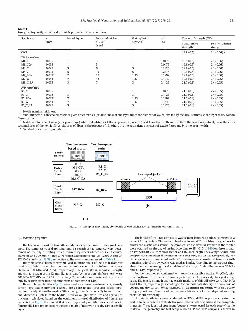
Table 1Strengthening configuration and materials properties of test specimens.
Specimen t*
(mm)No. of layers Measured thickness
of TRM(mm)
Ratio of axialstiffness**
qf***
(%)Concrete Strength (MPa)
Compressivestrength+
Tensile splittingstrength+
CON – – – – 19.9 (0.5) 2.1 (0.06) +
TRM-retrofittedM1_C 0.095 1 3 1 0.0475 19.9 (0.5) 2.1 (0.06)M1_CCo 0.095 1 5 1 0.0475 19.9 (0.5) 2.1 (0.06)M3_C 0.095 3 6 3 0.1425 19.9 (0.5) 2.1 (0.06)M5_C 0.095 5 10 5 0.2375 19.9 (0.5) 2.1 (0.06)M7_BCo 0.0371 7 17 1.06 0.1299 19.9 (0.5) 2.1 (0.06)M7_G 0.044 7 12 1.07 0.1540 19.9 (0.5) 2.1 (0.06)M3_C_EA 0.095 3 7 3 0.1425 21.7 (0.3) 2.4 (0.05)
FRP-retrofittedR1_C 0.095 1 1 0.0475 21.7 (0.3) 2.4 (0.05)R3_C 0.095 3 3 0.1425 21.7 (0.3) 2.4 (0.05)R7_BCo 0.0371 7 1.06 0.1299 21.7 (0.3) 2.4 (0.05)R7_G 0.044 7 1.07 0.1540 21.7 (0.3) 2.4 (0.05)R3_C_EA 0.095 3 3 0.1425 21.7 (0.3) 2.4 (0.05)
* Textile nominal thickness.** Axial stiffness of bare coated basalt or glass fibres textiles (axial stiffness of one layer times the number of layers) divided by the axial stiffness of one layer of dry carbon
fibres textile.*** Textile reinforcement ratio (as a percentage) which calculated as follows: qf = Af /bh, where b and h are the width and depth of the beam respectively. Af is the crosssectional area of the textile fibres, the area of fibres is the product of t*b, where t is the equivalent thickness of textile fibres and b is the beam width.
+ Standard deviation in parenthesis.
1350
M3_C_EAR3_C_EA
U-Shaped jacket
FRP
Textile+ epoxy resin
M1_CM1_CCo
M3_CM5_C
M3_C_EA
R1_CR3_C
R3_C_EA
CarbonTextile fibres
BasaltTextile fibres
M7_BCo R7_BCo
GlassTextile fibres
M7_G M7_G
Textile+ cement based mortar
TRM
(a)
(b)
250 250
Textile material
Fig. 2. (a) Group of specimens; (b) details of end anchorage system (dimensions in mm).
S.M. Raoof et al. / Construction and Building Materials 151 (2017) 279–291 281
2.2. Materials properties
The beams were cast on two different dates using the same mix design of con-crete. The compressive and splitting tensile strength of the concrete were deter-mined on the day of testing. Three concrete cylinders (dimensions of 150 mm-diameter and 300 mm-height) were tested according to the EN 12390-3 and EN12390-6 standards [38,39], respectively. The results are presented in Table 1.
The yield stress, ultimate strength, and ultimate strain of the 8 mm-diametersteel bars (which used for the tension and shear links reinforcement) was569 MPa, 631 MPa and 7.85%, respectively. The yield stress, ultimate strength,and ultimate strain of the 12 mm-diameter bars (compression reinforcement) were561 MPa, 637 MPa and 12.8%, respectively. These values were obtained experimen-tally by testing three identical specimens of each type of bars.
Three different textiles (Fig. 3) were used as external reinforcement, namelycarbon-fibre textile (dry and coated), glass-fibre textile (dry) and basalt fibre-textile (coated). All textiles made of fibre rovings distributed equally in two orthog-onal directions. Details of the textiles, such as weight, mesh size and equivalentthickness (calculated based on the equivalent smeared distribution of fibres), arepresented in Fig. 3. It is noted that seven layers of glass-fibre or coated basalt-fibre textile have approximately the same axial stiffness with one dry carbon textilelayer.
The binder of the TRM composite was cement-based with added polymers at aratio of 8:1 by weight. The water to binder ratio was 0.23, resulting in a good work-ability and plastic consistency. The compressive and flexural strength of the mortarwere obtained on the day of testing according to EN 1015-11 [40] on three mortarprisms with 40 � 40 mm cross section and 160 mm length. The average flexural andcompressive strengthen of the mortar were 39.2 MPa, and 9.8 MPa, respectively. Forthose specimens strengthened with FRP, an epoxy resin consisted of two parts witha mixing ratio of 4:1 by weight was used as binder. According to the product data-sheet, the tensile strength and modulus of elasticity of this adhesive was 30 MPaand 3.8 GPa, respectively.
For the specimen strengthened with coated carbon fibre textile (M1_CCo), priorto strengthening the textile was impregnated with a low viscosity, two-part epoxyresin. The tensile strength and the elastic modulus of this adhesive were 72.4 MPaand 3.18 GPa, respectively (according to the material data sheets). The procedure ofcoating the dry carbon textile included, impregnating the textile with this epoxyusing a plastic roll. The coated textiles were left to cure for two days before usingthem for strengthening.
Uniaxial tensile tests were conducted on TRM and FRP coupons comprising onetextile layer, in order to evaluate the main mechanical properties of the compositematerials. Three identical specimens (coupons) were tested for each type of textilematerial. The geometry and test setup of both FRP and TRM coupons is shown in
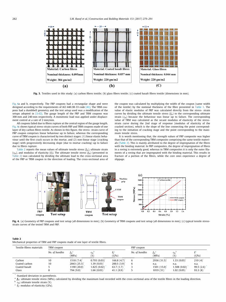
Material: Carbon fibres
Nominal thickness: 0.095mm
Weight: 384 gm/m2
(a)
Material: Glass fibres
Nominal thickness: 0.044 mm
Weight: 220 gm/m2
(C)
Material: Coated basalt fibres
Nominal thickness: 0.037 mm
Weight: 220 gm/m2
(b)
10 25 12
25
10 12
Fig. 3. Textiles used in this study: (a) carbon fibres textile; (b) glass fibres textile; (c) coated basalt fibres textile (dimensions in mm).
282 S.M. Raoof et al. / Construction and Building Materials 151 (2017) 279–291
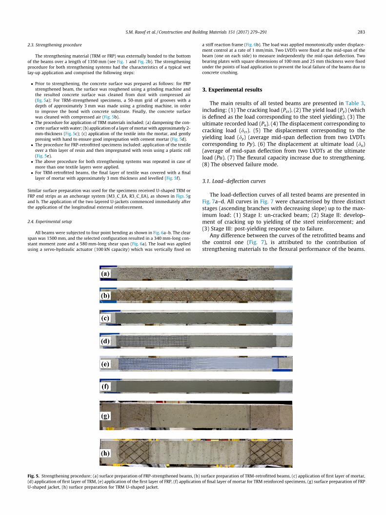
Fig. 4a and b, respectively. The FRP coupons had a rectangular shape and weredesigned according to the requirements of ACI 440.3R-33 code [41]. The TRM cou-pons had a dumbbell geometry and the test setup used was a modification of thesetups adopted in [3,42]. The gauge length of the FRP and TRM coupons was300 mm and 240 mm respectively. A monotonic load was applied under displace-ment control at a rate of 2 mm/min.
All coupons failed due to fibres rupture at the central region of the gauge length.Fig. 4c shows typical stress-strain curves of both FRP and TRM coupons made of onelayer of dry carbon fibres textile. As shown in this figure, the stress- strain curve ofFRP coupon comprises linear behaviour up to failure, whereas the correspondingcurve of TRM coupon is characterised by two distinct stages: (1) linear elastic beha-viour until the first crack occurs in the mortar, and (2) non-linear stage (crackingstage) with progressively decreasing slope (due to mortar cracking) up to failuredue to fibres rupture.
Table 2 reports the mean values of ultimate tensile stress (ffu), ultimate strain(efu), and modulus of elasticity (Ef). The ultimate tensile stress (ffu) (presented inTable 2) was calculated by dividing the ultimate load to the cross-sectional areaof the FRP or TRM coupon in the direction of loading. The cross-sectional area of
Fig. 4. (a) Geometry of FRP coupons and test setup (all dimensions in mm); (b) Geometstrain curves of the tested TRM and FRP.
Table 2Mechanical properties of TRM and FRP coupons made of one layer of textile fibres.
Textile-fibres materials TRM coupon
No. of bundles ffua
(MPa)efub
(%)Ef(G
Carbon 10 1518 (7.4)* 0.793 (0.03)* 16Coated carbon 10 2843 (25.3)* 1.39 (0.03)* 20Coated basalt 5 1190 (20.0) * 1.825 (0.02) * 63Glass 8 794 (9.0) * 1.66 (0.03) * 41
* Standard deviation in parenthesis.a ffu: ultimate tensile stress (MPa), calculated by dividing the maximum load recordeb efu: ultimate tensile strain (%).c Ef: modulus of elasticity (GPa).
the coupon was calculated by multiplying the width of the coupon (same widthof the textile) by the nominal thickness of the fibre presented in Table 1. Thevalue of elastic modulus of FRP was calculated directly from the stress- straincurves by dividing the ultimate tensile stress (ffu) to the corresponding ultimatestrain (efu) because the behaviour was linear up to failure. The correspondingvalue of TRM was calculated as the secant modulus of elasticity of the stress-strain curve during the 2nd stage of response (modulus of elasticity of thecracked section), which is the slope of the line connecting the point correspond-ing to the initiation of cracking stage and the point corresponding to the maxi-mum tensile stress.
It is worth mentioning that, the strength values of FRP composite was higherthan that of the corresponding TRM composite comprising the same textile materi-als (Table 2). This is mainly attributed to the degree of impregnation of the fibreswith the binding material. In FRP composites, the degree of impregnation of fibresin a roving is extremely good, whereas in TRM composites it is only the outer fila-ments of a roving that are impregnated with the binding material. This results infracture of a portion of the fibres, while the core ones experience a degree ofslippage.
ry of TRM coupons and test setup (all dimensions in mm); (c) typical tensile stress-
FRP coupon
c
Pa)No. of bundles ffu
a
(MPa)efub
(%)Ec
(GPa)
6.8 (4.7)* 6 2936 (31.5)* 1.33 (0.03)* 219 (4)*
0.5 (3.9)* 6 n.a. n.a. n.a..7 (1.7) * 3 1501 (15.0)* 1.508 (0.02) * 99.5 (2.6) *
.1 (0.9) * 5 1019 (31) * 1.02 (0.05) * 93.3 (8) *
d with the cross-sectional area of the textile fibres in the loading direction.
S.M. Raoof et al. / Construction and Building Materials 151 (2017) 279–291 283
2.3. Strengthening procedure
The strengthening material (TRM or FRP) was externally bonded to the bottomof the beams over a length of 1350 mm (see Fig. 1 and Fig. 2b). The strengtheningprocedure for both strengthening systems had the characteristics of a typical wetlay-up application and comprised the following steps:
� Prior to strengthening, the concrete surface was prepared as follows: for FRPstrengthened beam, the surface was roughened using a grinding machine andthe resulted concrete surface was cleaned from dust with compressed air(fig. 5a); For TRM-strengthened specimens, a 50-mm grid of grooves with adepth of approximately 3 mm was made using a grinding machine, in orderto improve the bond with concrete substrate. Finally, the concrete surfacewas cleaned with compressed air (Fig. 5b).
� The procedure for application of TRM materials included: (a) dampening the con-crete surface with water; (b) application of a layer of mortar with approximately 2-mm-thickness (Fig. 5c); (c) application of the textile into the mortar, and gentlypressing with hand to ensure good impregnation with cement mortar (Fig. 5d).
� The procedure for FRP-retrofitted specimens included: application of the textileover a thin layer of resin and then impregnated with resin using a plastic roll(Fig. 5e).
� The above procedure for both strengthening systems was repeated in case ofmore than one textile layers were applied.
� For TRM-retrofitted beams, the final layer of textile was covered with a finallayer of mortar with approximately 3 mm thickness and levelled (Fig. 5f).
Similar surface preparation was used for the specimens received U-shaped TRM orFRP end strips as an anchorage system (M3_C_EA, R3_C_EA), as shown in Figs. 5gand h. The application of the two layered U-jackets commenced immediately afterthe application of the longitudinal external reinforcement.
2.4. Experimental setup
All beams were subjected to four point bending as shown in Fig. 6a–b. The clearspan was 1500 mm, and the selected configuration resulted in a 340 mm-long con-stant moment zone and a 580 mm-long shear span (Fig. 6a). The load was appliedusing a servo-hydraulic actuator (100 kN capacity) which was vertically fixed on
Fig. 5. Strengthening procedure; (a) surface preparation of FRP-strengthened beams, (b)(d) application of first layer of TRM, (e) application of the first layer of FRP, (f) applicationU-shaped jacket, (h) surface preparation for TRM U-shaped jacket.
a stiff reaction frame (Fig. 6b). The load was applied monotonically under displace-ment control at a rate of 1 mm/min. Two LVDTs were fixed at the mid-span of thebeam (one on each side) to measure independently the mid-span deflection. Twobearing plates with square dimensions of 100 mm and 25 mm thickness were fixedunder the points of load application to prevent the local failure of the beams due toconcrete crushing.
3. Experimental results
The main results of all tested beams are presented in Table 3,including: (1) The cracking load (Pcr). (2) The yield load (Py) (whichis defined as the load corresponding to the steel yielding). (3) Theultimate recorded load (Pu). (4) The displacement corresponding tocracking load (dcr). (5) The displacement corresponding to theyielding load (dy) (average mid-span deflection from two LVDTscorresponding to Py). (6) The displacement at ultimate load (du)(average of mid-span deflection from two LVDTs at the ultimateload (Pu). (7) The flexural capacity increase due to strengthening.(8) The observed failure mode.
3.1. Load–deflection curves
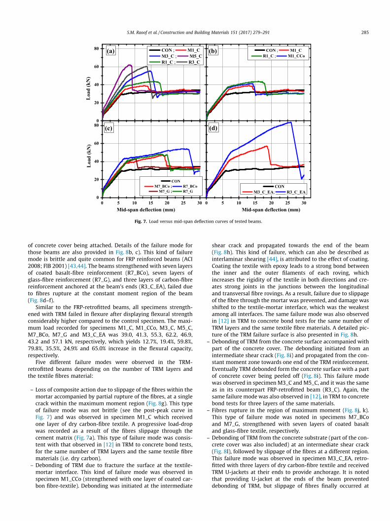
The load-deflection curves of all tested beams are presented inFig. 7a–d. All curves in Fig. 7 were characterised by three distinctstages (ascending branches with decreasing slope) up to the max-imum load: (1) Stage I: un-cracked beam; (2) Stage II: develop-ment of cracking up to yielding of the steel reinforcement; and(3) Stage III: post-yielding response up to failure.
Any difference between the curves of the retrofitted beams andthe control one (Fig. 7), is attributed to the contribution ofstrengthening materials to the flexural performance of the beams.
surface preparation of TRM-retrofitted beams, (c) application of first layer of mortar,of final layer of mortar for TRM reinforced specimens, (g) surface preparation of FRP
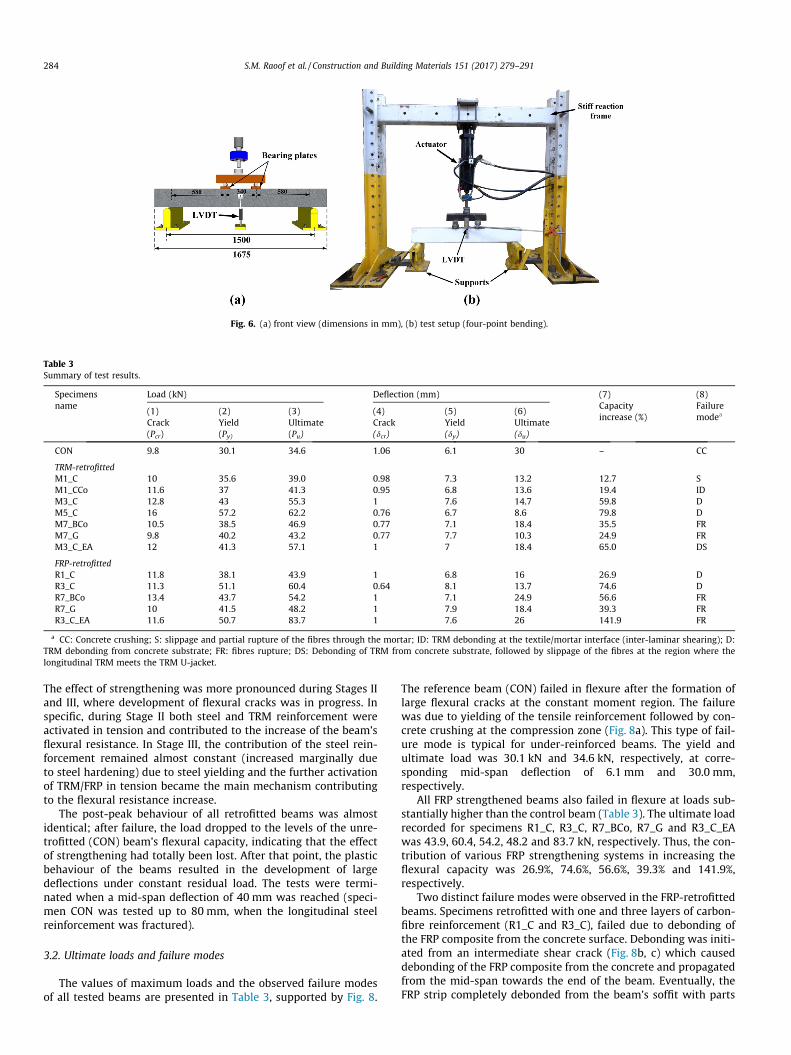
Fig. 6. (a) front view (dimensions in mm), (b) test setup (four-point bending).
Table 3Summary of test results.
Specimensname
Load (kN) Deflection (mm) (7)Capacityincrease (%)
(8)Failuremodea
(1)Crack(Pcr)
(2)Yield(Py)
(3)Ultimate(Pu)
(4)Crack(dcr)
(5)Yield(dy)
(6)Ultimate(du)
CON 9.8 30.1 34.6 1.06 6.1 30 – CC
TRM-retrofittedM1_C 10 35.6 39.0 0.98 7.3 13.2 12.7 SM1_CCo 11.6 37 41.3 0.95 6.8 13.6 19.4 IDM3_C 12.8 43 55.3 1 7.6 14.7 59.8 DM5_C 16 57.2 62.2 0.76 6.7 8.6 79.8 DM7_BCo 10.5 38.5 46.9 0.77 7.1 18.4 35.5 FRM7_G 9.8 40.2 43.2 0.77 7.7 10.3 24.9 FRM3_C_EA 12 41.3 57.1 1 7 18.4 65.0 DS
FRP-retrofittedR1_C 11.8 38.1 43.9 1 6.8 16 26.9 DR3_C 11.3 51.1 60.4 0.64 8.1 13.7 74.6 DR7_BCo 13.4 43.7 54.2 1 7.1 24.9 56.6 FRR7_G 10 41.5 48.2 1 7.9 18.4 39.3 FRR3_C_EA 11.6 50.7 83.7 1 7.6 26 141.9 FR
a CC: Concrete crushing; S: slippage and partial rupture of the fibres through the mortar; ID: TRM debonding at the textile/mortar interface (inter-laminar shearing); D:TRM debonding from concrete substrate; FR: fibres rupture; DS: Debonding of TRM from concrete substrate, followed by slippage of the fibres at the region where thelongitudinal TRM meets the TRM U-jacket.
284 S.M. Raoof et al. / Construction and Building Materials 151 (2017) 279–291
The effect of strengthening was more pronounced during Stages IIand III, where development of flexural cracks was in progress. Inspecific, during Stage II both steel and TRM reinforcement wereactivated in tension and contributed to the increase of the beam’sflexural resistance. In Stage III, the contribution of the steel rein-forcement remained almost constant (increased marginally dueto steel hardening) due to steel yielding and the further activationof TRM/FRP in tension became the main mechanism contributingto the flexural resistance increase.
The post-peak behaviour of all retrofitted beams was almostidentical; after failure, the load dropped to the levels of the unre-trofitted (CON) beam’s flexural capacity, indicating that the effectof strengthening had totally been lost. After that point, the plasticbehaviour of the beams resulted in the development of largedeflections under constant residual load. The tests were termi-nated when a mid-span deflection of 40 mm was reached (speci-men CON was tested up to 80 mm, when the longitudinal steelreinforcement was fractured).
3.2. Ultimate loads and failure modes
The values of maximum loads and the observed failure modesof all tested beams are presented in Table 3, supported by Fig. 8.
The reference beam (CON) failed in flexure after the formation oflarge flexural cracks at the constant moment region. The failurewas due to yielding of the tensile reinforcement followed by con-crete crushing at the compression zone (Fig. 8a). This type of fail-ure mode is typical for under-reinforced beams. The yield andultimate load was 30.1 kN and 34.6 kN, respectively, at corre-sponding mid-span deflection of 6.1 mm and 30.0 mm,respectively.
All FRP strengthened beams also failed in flexure at loads sub-stantially higher than the control beam (Table 3). The ultimate loadrecorded for specimens R1_C, R3_C, R7_BCo, R7_G and R3_C_EAwas 43.9, 60.4, 54.2, 48.2 and 83.7 kN, respectively. Thus, the con-tribution of various FRP strengthening systems in increasing theflexural capacity was 26.9%, 74.6%, 56.6%, 39.3% and 141.9%,respectively.
Two distinct failure modes were observed in the FRP-retrofittedbeams. Specimens retrofitted with one and three layers of carbon-fibre reinforcement (R1_C and R3_C), failed due to debonding ofthe FRP composite from the concrete surface. Debonding was initi-ated from an intermediate shear crack (Fig. 8b, c) which causeddebonding of the FRP composite from the concrete and propagatedfrom the mid-span towards the end of the beam. Eventually, theFRP strip completely debonded from the beam’s soffit with parts
0
20
40
60
80
0
20
40
60
80
0 5 10 15 20 25 30 0 5 10 15 20 25 30
Loa
d (k
N)
(d)(c)
(b)
Loa
d (k
N)
CON ; M1_CM3_C ; M5_CR1_C ; R3_C
(a)
CONM7_BCo ; R7_BCo
M7_G ; R7_G
CON ; M1_CR1_C ; M1_CCo
Mid-span deflection (mm) Mid-span deflection (mm)
CONM3_C_EA; R3_C_EA
Fig. 7. Load versus mid-span deflection curves of tested beams.
S.M. Raoof et al. / Construction and Building Materials 151 (2017) 279–291 285
of concrete cover being attached. Details of the failure mode forthose beams are also provided in Fig. 8b, c). This kind of failuremode is brittle and quite common for FRP reinforced beams (ACI2008; FIB 2001) [43,44]. The beams strengthened with seven layersof coated basalt-fibre reinforcement (R7_BCo), seven layers ofglass-fibre reinforcement (R7_G), and three layers of carbon-fibrereinforcement anchored at the beam’s ends (R3_C_EA), failed dueto fibres rupture at the constant moment region of the beam(Fig. 8d–f).
Similar to the FRP-retrofitted beams, all specimens strength-ened with TRM failed in flexure after displaying flexural strengthconsiderably higher compared to the control specimen. The maxi-mum load recorded for specimens M1_C, M1_CCo, M3_C, M5_C,M7_BCo, M7_G and M3_C_EA was 39.0, 41.3, 55.3, 62.2, 46.9,43.2 and 57.1 kN, respectively, which yields 12.7%, 19.4%, 59.8%,79.8%, 35.5%, 24.9% and 65.0% increase in the flexural capacity,respectively.
Five different failure modes were observed in the TRM-retrofitted beams depending on the number of TRM layers andthe textile fibres material:
– Loss of composite action due to slippage of the fibres within themortar accompanied by partial rupture of the fibres, at a singlecrack within the maximum moment region (Fig. 8g). This typeof failure mode was not brittle (see the post-peak curve inFig. 7) and was observed in specimen M1_C which receivedone layer of dry carbon-fibre textile. A progressive load-dropwas recorded as a result of the fibres slippage through thecement matrix (Fig. 7a). This type of failure mode was consis-tent with that observed in [12] in TRM to concrete bond tests,for the same number of TRM layers and the same textile fibrematerials (i.e. dry carbon).
– Debonding of TRM due to fracture the surface at the textile-mortar interface. This kind of failure mode was observed inspecimen M1_CCo (strengthened with one layer of coated car-bon fibre-textile). Debonding was initiated at the intermediate
shear crack and propagated towards the end of the beam(Fig. 8h). This kind of failure, which can also be described asinterlaminar shearing [44], is attributed to the effect of coating.Coating the textile with epoxy leads to a strong bond betweenthe inner and the outer filaments of each roving, whichincreases the rigidity of the textile in both directions and cre-ates strong joints in the junctions between the longitudinaland transversal fibre rovings. As a result, failure due to slippageof the fibre through the mortar was prevented, and damage wasshifted to the textile-mortar interface, which was the weakestamong all interfaces. The same failure mode was also observedin [12] in TRM to concrete bond tests for the same number ofTRM layers and the same textile fibre materials. A detailed pic-ture of the TRM failure surface is also presented in Fig. 8h.
– Debonding of TRM from the concrete surface accompanied withpart of the concrete cover. The debonding initiated from anintermediate shear crack (Fig. 8i) and propagated from the con-stant moment zone towards one end of the TRM reinforcement.Eventually TRM debonded form the concrete surface with a partof concrete cover being peeled off (Fig. 8i). This failure modewas observed in specimen M3_C and M5_C, and it was the sameas in its counterpart FRP-retrofitted beam (R3_C). Again, thesame failure mode was also observed in [12], in TRM to concretebond tests for three layers of the same materials.
– Fibres rupture in the region of maximum moment (Fig. 8j, k).This type of failure mode was noted in specimens M7_BCoand M7_G, strengthened with seven layers of coated basaltand glass-fibre textile, respectively.
– Debonding of TRM from the concrete substrate (part of the con-crete cover was also included) at an intermediate shear crack(Fig. 8l), followed by slippage of the fibres at a different region.This failure mode was observed in specimen M3_C_EA, retro-fitted with three layers of dry carbon-fibre textile and receivedTRM U-jackets at their ends to provide anchorage. It is notedthat providing U-jacket at the ends of the beam preventeddebonding of TRM, but slippage of fibres finally occurred at
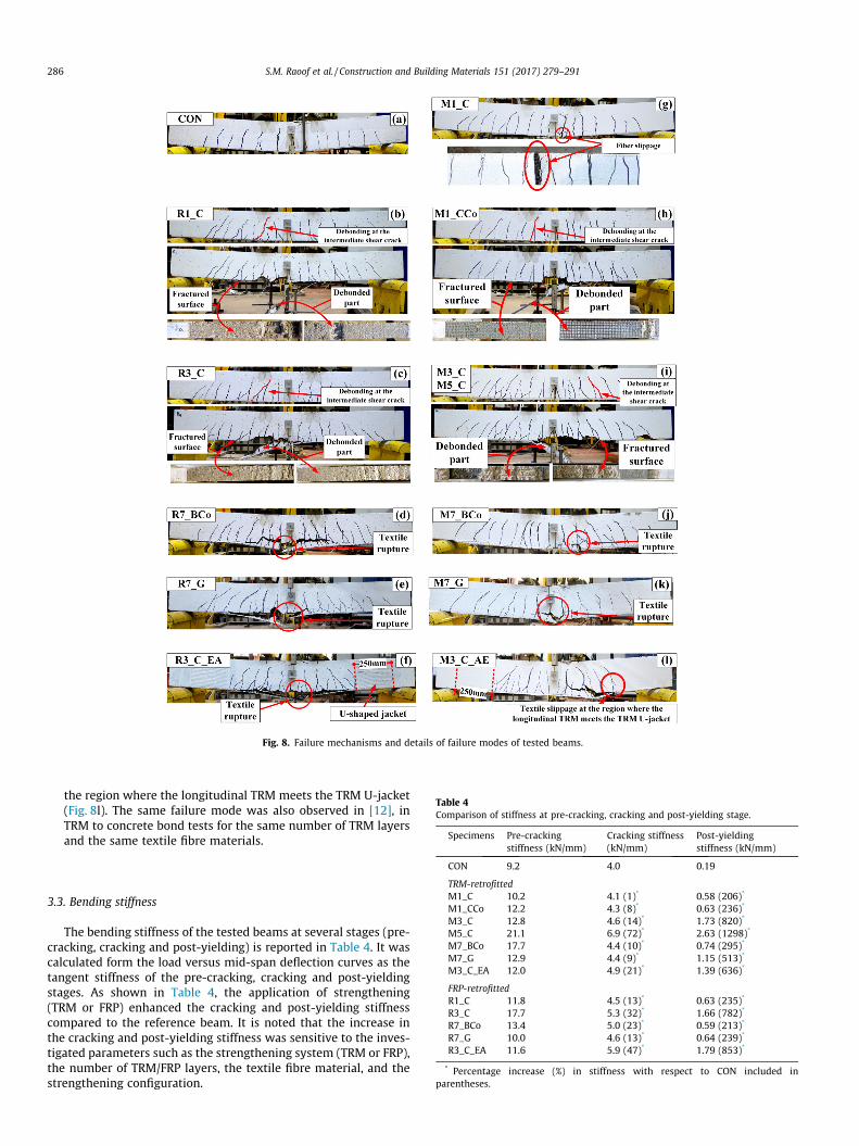
Fig. 8. Failure mechanisms and details of failure modes of tested beams.
Table 4Comparison of stiffness at pre-cracking, cracking and post-yielding stage.
Specimens Pre-crackingstiffness (kN/mm)
Cracking stiffness(kN/mm)
Post-yieldingstiffness (kN/mm)
286 S.M. Raoof et al. / Construction and Building Materials 151 (2017) 279–291
the region where the longitudinal TRM meets the TRM U-jacket(Fig. 8l). The same failure mode was also observed in [12], inTRM to concrete bond tests for the same number of TRM layersand the same textile fibre materials.
CON 9.2 4.0 0.19
TRM-retrofittedM1_C 10.2 4.1 (1)* 0.58 (206)*
M1_CCo 12.2 4.3 (8)* 0.63 (236)*
M3_C 12.8 4.6 (14)* 1.73 (820)*
M5_C 21.1 6.9 (72)* 2.63 (1298)*
M7_BCo 17.7 4.4 (10)* 0.74 (295)*
M7_G 12.9 4.4 (9)* 1.15 (513)*
M3_C_EA 12.0 4.9 (21)* 1.39 (636)*
FRP-retrofittedR1_C 11.8 4.5 (13)* 0.63 (235)*
R3_C 17.7 5.3 (32)* 1.66 (782)*
R7_BCo 13.4 5.0 (23)* 0.59 (213)*
R7_G 10.0 4.6 (13)* 0.64 (239)*
R3_C_EA 11.6 5.9 (47)* 1.79 (853)*
* Percentage increase (%) in stiffness with respect to CON included inparentheses.
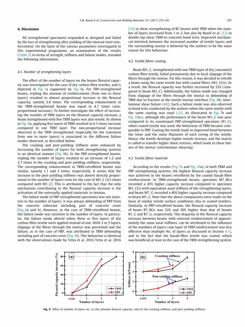
3.3. Bending stiffness
The bending stiffness of the tested beams at several stages (pre-cracking, cracking and post-yielding) is reported in Table 4. It wascalculated form the load versus mid-span deflection curves as thetangent stiffness of the pre-cracking, cracking and post-yieldingstages. As shown in Table 4, the application of strengthening(TRM or FRP) enhanced the cracking and post-yielding stiffnesscompared to the reference beam. It is noted that the increase inthe cracking and post-yielding stiffness was sensitive to the inves-tigated parameters such as the strengthening system (TRM or FRP),the number of TRM/FRP layers, the textile fibre material, and thestrengthening configuration.
S.M. Raoof et al. / Construction and Building Materials 151 (2017) 279–291 287
4. Discussion
All strengthened specimens responded as designed and failedby the loss of strengthening after yielding of the internal steel rein-forcement. On the basis of the various parameters investigated inthis experimental programme, an examination of the results(Table 3) in terms of strength, stiffness and failure modes, revealedthe following information.
4.1. Number of strengthening layers
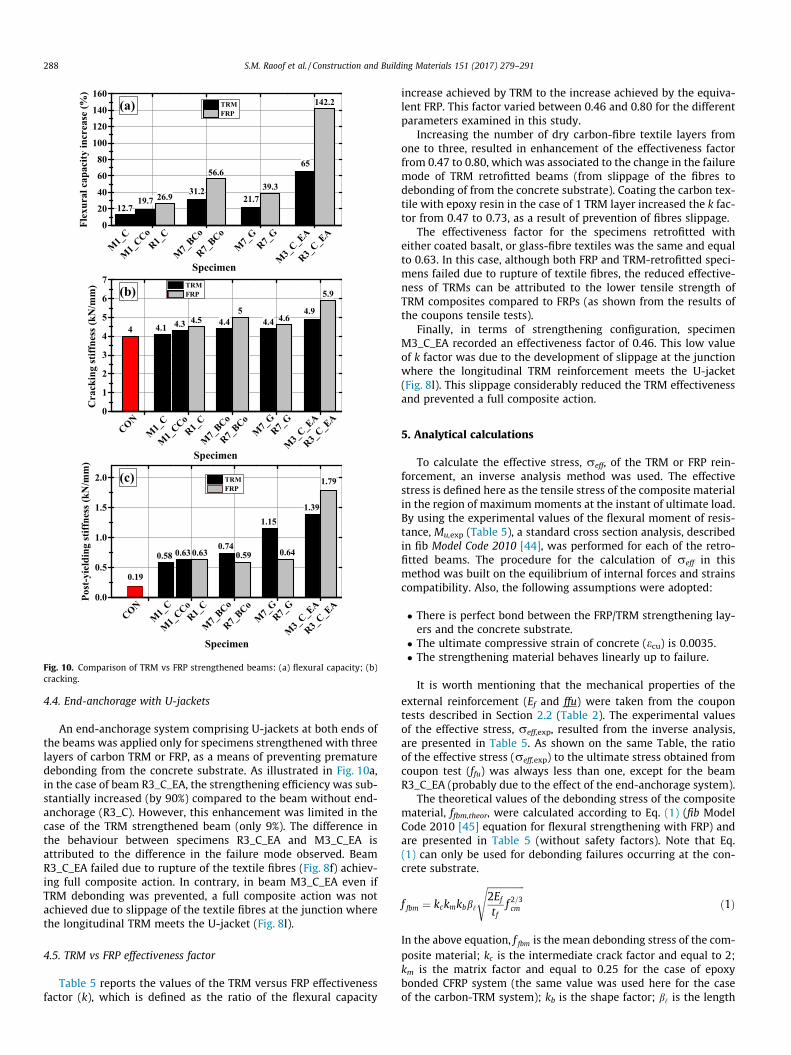
The effect of the number of layers on the beams flexural capac-ity was investigated for the case of dry carbon-fibre textiles, and isdepicted in Fig. 7a supported by Fig. 9a. For FRP-strengthenedbeams, tripling the amount of reinforcement (from one to threelayers) resulted in almost proportional increase in the flexuralcapacity, namely 2.8 times. The corresponding enhancement inthe TRM-strengthened beams was equal to 4.7 times (non-proportional increase). To further investigate the effect of increas-ing the number of TRM layers on the flexural capacity increase, abeam strengthened with five TRM layers was also tested. As shownin Fig. 9a, applying five layers of TRM resulted in 6.3 times increasecompared to one TRM layer. The non-proportional increaseobserved in the TRM strengthened (especially for the transitionfrom one to more layers) is associated to the different failuremodes observed, as described below.
The cracking and post-yielding stiffness were enhanced byincreasing the number of layers for both strengthening systemsin an identical manner (Fig. 9b). In the FRP-strengthened beams,tripling the number of layers resulted in an increase of 1.2 and2.7 times in the cracking and post-yielding stiffness, respectively.The corresponding enhancement in TRM-retrofitted beams wassimilar, namely 1.1 and 3 times, respectively. It seems that theincrease in the post-yielding stiffness was almost directly propor-tional to the number of layers even for the case of M5_C (4.5 timescompared with M1_C). This is attributed to the fact that the onlymechanism contributing to the flexural capacity increase is theactivation of the externally applied materials in tension.
The failure mode of FRP strengthened specimens was not sensi-tive to the number of layers; it was always debonding of FRP fromthe concrete substrate including part of concrete cover(Fig. 8a and b). However, in the case of TRM-retrofitted beams,the failure mode was sensitive to the number of layers. In particu-lar, the failure mode altered when three or five layers of drycarbon-fibre textile were applied instead of one. With 3 or 5 layers,slippage of the fibres through the mortar was prevented and thefailure, as in the case of FRP, was attributed to TRM debondingincluding part of concrete cover (Fig. 8i). This behaviour is identicalwith the observations made by Tetta et al. 2016 Tetta et al. 2016
0
20
40
60
80
Flex
ural
cap
acity
incr
ease
(%)
Number of layers
TRM FRP
(a)
531CON
Fig. 9. Effect of number of layers on: (a) the ultimate flexural capa
[16] in shear strengthening of RC beams with TRM when the num-ber of layers increased from 1 to 2, but also by Raoof et al. [12] indouble-lap shear TRM-to-concrete bond tests. Improved mechani-cal interlock between the increased number of textile layers andthe surrounding mortar is believed by the authors to be the mainreason for this behaviour.
4.2. Textile-fibres coating
BeamM1_C, strengthened with one TRM layer of dry (uncoated)carbon-fibre textile, failed prematurely due to local slippage of thefibres through the mortar. For this reason, it was decided to retrofita beam using the same textile but with coated fibres (M1_CCo). Asa result, the flexural capacity was further increased by 52% (com-pared to beam M1_C). Additionally, the failure mode was changedfrom slippage of the fibres through the mortar to debonding ofTRM due to fracture at the textile-mortar interface (Fig. 8h; inter-laminar shear failure [44]). Such a failure mode was also observedin bond tests conducted by the authors when the same textile withthe same coating was used [12]. As illustrated in Fig. 7b andFig. 10a-c, although the performance of the beam M1_C was poorcompared to its counterpart FRP-strengthened specimen (R1_C),when coated textile was used, the behaviour of TRM became com-parable to FRP. Coating the textile leads to improved bond betweenthe inner and the outer filaments of each roving of the textile.Hence, the textile develops higher tensile stresses, and the matrixis called to transfer higher shear stresses, which leads to shear fail-ure of the mortar (interlaminar shearing).
4.3. Textile-fibres material
According to the results (Fig. 7c and Fig. 10a), in both TRM andFRP strengthening systems, the highest flexural capacity increasewas achieved in the beams retrofitted by the coated basalt-fibrereinforcement. In TRM-strengthened beams, specimen M7_BCorecorded a 45% higher capacity increase compared to specimenM1_CCo with equivalent axial stiffness of the strengthening layers,and beamM7_G recorded a 49% higher capacity increase comparedto beamM1_C. Note that the above comparisons were made on thebasis of similar textile surface conditions (dry or coated textiles).Similarly, in FRP-retrofitted beams, the flexural capacity increaseof beam R7_BCo was 52% and 30% higher than that of beamsR1_C and R7_G, respectively. This disparity in the flexural capacityincrease between beams with external reinforcement of approxi-mately the same axial stiffness, can be attributed to the influenceof the numbers of layers (one layer of TRM reinforcement was lesseffective than multiple No. of layers as discussed in Section 4.1),and to the fact that the basalt-fibre textile was coated, whichwas beneficial at least in the case of the TRM strengthening system.
0
2
4
6
8Cracking stiffness
53
(b)
Post-yielding stiffness
1CON
Stiff
ness
(kN
/mm
)
Number of layers
TRM FRP
city; and (b) the cracking stiffness, and post-yielding stiffness.
12.719.7
31.221.7
65
26.9
56.639.3
142.2
M1_
CCo
Specimen
M1_
CR1_
C
R3_C_E
A
M3_
C_EA
R7_G
M7_
G
R7_BCo
M7_
BCo
4.1 4.3 4.4 4.44.9
44.5
54.6
5.9
0.58 0.630.74
1.151.39
0.19
0.63 0.59 0.64
1.79
0
1
2
3
4
5
6
7(b)
Cra
ckin
g st
iffne
ss (k
N/m
m) TRM
FRP
0.0
0.5
1.0
1.5
2.0 (c)
Post
-yie
ldin
g st
iffne
ss (k
N/m
m)
TRM FRP
CON
M1_
CCo
Specimen
M1_
CR1_
C
R7_BCo
R3_C_E
A
M3_
C_EA
R7_G
M7_
G
M7_
BCo
CON
M1_
CCo
Specimen
M1_
CR1_
C
R7_BCo
R3_C_E
A
M3_
C_EA
R7_G
M7_
G
M7_
BCo
0
20
40
60
80
100
120
140
160Fl
exur
al c
apac
ity in
crea
se (%
)
TRM FRP
(a)
Fig. 10. Comparison of TRM vs FRP strengthened beams: (a) flexural capacity; (b)cracking.
288 S.M. Raoof et al. / Construction and Building Materials 151 (2017) 279–291
4.4. End-anchorage with U-jackets
An end-anchorage system comprising U-jackets at both ends ofthe beams was applied only for specimens strengthened with threelayers of carbon TRM or FRP, as a means of preventing prematuredebonding from the concrete substrate. As illustrated in Fig. 10a,in the case of beam R3_C_EA, the strengthening efficiency was sub-stantially increased (by 90%) compared to the beam without end-anchorage (R3_C). However, this enhancement was limited in thecase of the TRM strengthened beam (only 9%). The difference inthe behaviour between specimens R3_C_EA and M3_C_EA isattributed to the difference in the failure mode observed. BeamR3_C_EA failed due to rupture of the textile fibres (Fig. 8f) achiev-ing full composite action. In contrary, in beam M3_C_EA even ifTRM debonding was prevented, a full composite action was notachieved due to slippage of the textile fibres at the junction wherethe longitudinal TRM meets the U-jacket (Fig. 8l).
4.5. TRM vs FRP effectiveness factor
Table 5 reports the values of the TRM versus FRP effectivenessfactor (k), which is defined as the ratio of the flexural capacity
increase achieved by TRM to the increase achieved by the equiva-lent FRP. This factor varied between 0.46 and 0.80 for the differentparameters examined in this study.
Increasing the number of dry carbon-fibre textile layers fromone to three, resulted in enhancement of the effectiveness factorfrom 0.47 to 0.80, which was associated to the change in the failuremode of TRM retrofitted beams (from slippage of the fibres todebonding of from the concrete substrate). Coating the carbon tex-tile with epoxy resin in the case of 1 TRM layer increased the k fac-tor from 0.47 to 0.73, as a result of prevention of fibres slippage.
The effectiveness factor for the specimens retrofitted witheither coated basalt, or glass-fibre textiles was the same and equalto 0.63. In this case, although both FRP and TRM-retrofitted speci-mens failed due to rupture of textile fibres, the reduced effective-ness of TRMs can be attributed to the lower tensile strength ofTRM composites compared to FRPs (as shown from the results ofthe coupons tensile tests).
Finally, in terms of strengthening configuration, specimenM3_C_EA recorded an effectiveness factor of 0.46. This low valueof k factor was due to the development of slippage at the junctionwhere the longitudinal TRM reinforcement meets the U-jacket(Fig. 8l). This slippage considerably reduced the TRM effectivenessand prevented a full composite action.
5. Analytical calculations
To calculate the effective stress, reff, of the TRM or FRP rein-forcement, an inverse analysis method was used. The effectivestress is defined here as the tensile stress of the composite materialin the region of maximummoments at the instant of ultimate load.By using the experimental values of the flexural moment of resis-tance, Mu,exp (Table 5), a standard cross section analysis, describedin fib Model Code 2010 [44], was performed for each of the retro-fitted beams. The procedure for the calculation of reff in thismethod was built on the equilibrium of internal forces and strainscompatibility. Also, the following assumptions were adopted:
� There is perfect bond between the FRP/TRM strengthening lay-ers and the concrete substrate.
� The ultimate compressive strain of concrete (ecu) is 0.0035.� The strengthening material behaves linearly up to failure.
It is worth mentioning that the mechanical properties of the
external reinforcement (Ef and ffu) were taken from the coupontests described in Section 2.2 (Table 2). The experimental valuesof the effective stress, reff,exp, resulted from the inverse analysis,are presented in Table 5. As shown on the same Table, the ratioof the effective stress (reff,exp) to the ultimate stress obtained fromcoupon test (ffu) was always less than one, except for the beamR3_C_EA (probably due to the effect of the end-anchorage system).
The theoretical values of the debonding stress of the compositematerial, ffbm,theor, were calculated according to Eq. (1) (fib ModelCode 2010 [45] equation for flexural strengthening with FRP) andare presented in Table 5 (without safety factors). Note that Eq.(1) can only be used for debonding failures occurring at the con-crete substrate.
f fbm ¼ kckmkbb‘
ffiffiffiffiffiffiffiffiffiffiffiffiffiffiffiffi2Ef
tff 2=3cm
sð1Þ
In the above equation, f fbm is the mean debonding stress of the com-posite material; kc is the intermediate crack factor and equal to 2;km is the matrix factor and equal to 0.25 for the case of epoxybonded CFRP system (the same value was used here for the caseof the carbon-TRM system); kb is the shape factor; b‘ is the length
Table 5Effectiveness factor, experimental values of ultimate moment capacity and effective stress in TRM/FRP reinforcement.
Specimen TRM vs FRP effectivenessfactor, k
Mu,exp.*
kN.mreff,exp.
**. F.M.*** ffu
+ (MPa) reff,exp./ffu ffbm,theor++ reff,exp./ffbm,theor ff, bond
a F.M.b ff, bond/ffu
CON – 10.03 – – –
TRM-retrofittedM1_C 0.47 11.31 1368 S 1518 0.90 n.a. n.a. 915 S 0.75M1_CCo 0.72 12.01 1825 ID 2843 0.64 n.a. n.a. 1572 ID 0.55M3_C 0.80 16.04 1434 D 1518 0.94 1466 0.98 790 D 0.55M5_C n.a. 18.04 1126 D 1518 0.74 1136 0.99 n.a. D n.a.M7_BCo 0.63 13.60 1019 FR 1190 0.86 n.a. n.a. 1046c FRc 0.88M7_G 0.63 12.53 658 FR 794 0.83 n.a. n.a. 709c FRc 0.89M3_C_EA 0.46 16.56 1501 D 1518 0.99 n.a. n.a. 877 D 0.58
FRP-retrofittedR1_C n.a. 12.73 2190 D 2936 0.75 2995 0.73 n.a. n.a. n.a.R3_C n.a. 17.52 1796 D 2936 0.61 1729 1.04 n.a. n.a. n.a.R7_BCo n.a. 15.72 1493 FR 1501 0.99 n.a. n.a. n.a. n.a. n.a.R7_G n.a. 13.98 914 FR 1019 0.90 n.a. n.a. n.a. n.a. n.a.R3_C_EA n.a. 24.30 3110 FR 2936 1.06 n.a. n.a. n.a. n.a. n.a.
* Ultimate moment capacity obtained experimentally.** Effective stress in TRM/FRP reinforcement calculated based on experimental results.*** Failure mode of strengthened beams (see Table 3).+ Ultimate stress in the textiles fibres obtained from coupon test (Table 2).
++ Mean debonding stress in TRM/FRP reinforcement calculated according to Eq. (1).a Average stress in TRM reinforcement obtained from bond test included in Raoof et al. (2016) [12].b Failure mode observed in bond test included in Raoof et al. (2016) [12].c Bond tests currently carried on.
S.M. Raoof et al. / Construction and Building Materials 151 (2017) 279–291 289
factor which can be taken equal to 1; Ef is the elastic modulus thecomposite material (obtained from coupon test); tf is the equivalentthickness of the textile and fcm is the concrete compressive strength;and the shape factor (kb) was calculated from Eq. (2) below:
kb ¼ffiffiffiffiffiffiffiffiffiffiffiffiffiffiffiffiffiffi2� bf =b1þ bf =b
sP 1 ð2Þ
where; bf is the width of the composite, and b is the width of thebeam.
Eq. (1) was used here to calculate both FRP and TRM debondingstresses in the cases of debonding failures. A comparison of thestresses calculated according to Eq. (1) with the experimental datais presented in Table 5. It was found that the debonding stress cal-culated by Eq. (1) is in a good agreement with the experimentalresults of that beams reinforced with high FRP and TRM reinforce-ment ratio (M3_C, M5_C and R3_C) and failed due to debonding ofFRP or TRM from the concrete substrate including part of the con-crete cover.
Fig. 11 shows the relationship between the effective stressobtained experimentally reff,exp. and the product qf Ef; togetherwith the curve corresponding to Eq. (1). Where qf is the textile
0
500
1000
1500
2000
2500
3000
0.0 0.2 0.4 0.6 0.8 1.0
Debonding
Slippage
Rupture
(a)
TRM strengthened beams
σ eff
ρf
fib [45]; M1_C M1_CCo; M3_C M5_C; M7_BCo M7_G; M3_C_EA
Fig. 11. Experimentally obtained effective stress versus qf Ef and comparison with thestrengthened beams.
fibres reinforcement ratio (qf = Af/bh), and Ef is the modulus of elas-ticity of the composite material obtained from coupon tests. It isclear from this figure that the effective stress developed in the tex-tile fibres reinforcement is inversely proportional to the productqfEf when the failure is associated to debonding of the externallybonded reinforcement, regardless the binding material (epoxyresin or mortar). This trend of the effective stress is consistent withthe trend of the theoretical stress calculated by Eq. (1) and shownin Fig. 11a, and b (dash line).
Based on the above findings, in design of flexural retrofittingwith TRM system, the effective stress can be the minimum valueobtained from coupon tests (ffu) and Eq. (1), applying the samesafety factors as in FRP systems until more data become availableand a semi-probabilistic approach can be applied to obtain TRM-specific safety factors. Nevertheless, this design approach is sug-gested to be used only when the failure mode is either TRMdebonding at an intermediate crack or fibres rupture. Accordingto the results of the present experimental study, this applies whenmore than 2 TRM layers are used for retrofitting. It is evident thatmore experimental data is required for a refined design modelwhich will consider all different failure modes observed, includingthe slippage of the TRM reinforcement in flexural cracks.
0.0 0.2 0.4 0.6 0.8 1.0 1.2
Ef
Rupture
(b)
FRP strengthened beams
fib [45]; R1_C R3_C; R7_BCo R7_G; R3_C_EA
Rupture
Debonding
theoretical formula suggested by fib [45]; (a) TRM-strengthened beams; (b) FRP-
290 S.M. Raoof et al. / Construction and Building Materials 151 (2017) 279–291
Table 5 also compares the effective stress in the TRM composite(reff,exp) with the debonding stress obtained through direct shear-bond tests (ff, bond) in the study of Raoof et al. 2016 [12]. The com-parison is made on the basis of the same number of TRM layersused in both studies, with the same materials. The ff, bond valuesused for the comparison correspond to 200 mm bond length, whichwas found to be the effective bond length (in which the bondstrength is not significantly increased beyond this length).Although identical failure modes were noted in both flexural andbond tests (for identical specimens having the same textile fibrematerials and number of TRM layers) the debonding stressesrecorded at failure were lower in the bond tests, leading to lowerutilisation of the textile fibres reinforcement.
6. Conclusions
This study investigated experimentally the performance of TRMand FRP composite in flexural strengthening of RC beams. Severalparameters were examined namely: (a) the strengthening material(TRM and FRP); (b) the number of FRP/TRM layers; (c) the textilesurface condition; (d) the textile-fibre materials and (e) the endanchorage system. The obtained results revealed the followingconclusions:
1. The effectiveness of TRM system in increasing the loading car-rying capacity of retrofitted beams was less than that of FRP.Nevertheless, TRM effectiveness was sensitive to the numberof layers. It was found that the effectiveness factor increasedfrom 0.47 to 0.80 when the number of TRM layers increasedfrom 1 to 3.
2. Coating the carbon fibres textile with epoxy adhesive signifi-cantly enhanced the performance of TRM materials. Whenone layer of coated carbon textile was used instead of one layerof dry carbon textile, the flexural capacity gain increased from12.7 to 19.7% (about 55% enhancement).
3. Different textile fibres materials (carbon, coated basalt, andglass) having approximately the same axial stiffness resultedin different flexural capacity increases. In both strengtheningsystems, seven coated basalt- fibre textile layers recorded thehighest flexural capacity increase, followed by seven dryglass- fibre textile layers, and finally by one carbon- fibre textilelayer. This variance in the performance was related to the effectof number of layers (in both FRP and TRM strengthening sys-tems), but also to the textile surface condition (dry or coatedtextiles) in TRM strengthening system.
4. Providing end-anchorage with U-jackets to FRP-retrofittedbeams resulted in 90% enhancement in the flexural capacitycompared to non- anchorage beam. However, the correspond-ing enhancement in TRM-retrofitted beam was limited (9%)and was attributed to the presence of slippage of the textile atthe U-jacket – longitudinal TRM sheets.
5. Two types of failure mode were observed in the FRP-retrofittedbeams, these failure modes were: debonding from concretesubstrate (for specimens M1_C and M3_C), and fibres ruptureat the constant moment zone (for specimens M7_BCo, M7_Gand M3_C_EA). Whereas, in the TRM-retrofitted beams five dif-ferent failure modes were observed, namely: slippage of therovings through the surrounding cement mortar (specimenM1_C), fracture the surface at the textile- matrix interface(interlaminar debonding- specimen M1_CCo), debonding ofTRM from the concrete with peeling off parts concrete cover(specimen M3_C and M5_C), and rupture of the textile fibresat the constant moment zone (M7_BCo and M7_G). These fail-ure modes were found to be sensitive to the number of TRMlayers, the textile fibres materials (carbon, coated basalt or glassfibres), and the textile surface condition (dry or coated fibres).
6. For both strengthening systems (TRM and FRP), the crackingand post-yielding stiffness of strengthened beams was substan-tially enhanced compared to the unstrengthened beam (up to72% and 1298%, respectively).
7. A formula proposed by fib 2010 [45] was used to predict thedebonding stress in FRP reinforced for those specimens faileddue to debonding of FRP from concrete substrate. This formulawas also used to predict the debonding stress of TRM reinforce-ment for those specimens that have same failure mode (i.e.debonding). It was found that this formula is in a good agree-ment with the effective stress calculated based on the experi-mental results providing that TRM properties are obtainedfrom coupon tests. The above-mentioned conclusions shouldbe treated carefully. They are based on a limited number of testson half-scale beams and specific type of textile fibre materials.More research is required including different types of textilematerials and full-scale beams. This would also help to confirmthe reliability of existing design models for FRP or the develop-ment of new reliable ones.
Acknowledgements
The authors wish to thank the technical staff in the structureslab, and the PhD candidate Zoi Tetta at the University of Notting-ham for their help. This work was supported by the Engineeringand Physical Sciences Research Council [grant number EP/L50502X/1] UK, and the research described in this paper has beenco-financed by the Higher Committee for Education Developmentin Iraq (HCED).
References
[1] D.A. Bournas, P.V. Lontou, C.G. Papanicolaou, T.C. Triantafillou, Textile-reinforced mortar versus fiber-reinforced polymer confinement in reinforcedconcrete columns, ACI Struct. J. 104 (6) (2007).
[2] T.C. Triantafillou, C.G. Papanicolaou, Shear strengthening of reinforcedconcrete members with textile reinforced mortar (TRM) jackets, Mater.Struct. 39 (1) (2006) 93–103.
[3] W. Brameshuber, Report 36: Textile Reinforced Concrete-State-of-the-ArtReport of RILEM TC 201-TRC, RILEM Publications, 2006.
[4] C. Carloni, D.A. Bournas, F.G. Carozzi, T. D’Antino, G. Fava, F. Focacci, FiberReinforced Composites with Cementitious (inorganic) Matrix. DesignProcedures for the Use of Composites in Strengthening of ReinforcedConcrete Structures, Springer, 2016. p. 349–392.
[5] S.M. Raoof, D.A. Bournas, Bond between TRM versus FRP composites andconcrete at high temperatures, Compos. Eng. (2017), http://dx.doi.org/10.1016/j.compositesb.2017.05.064.
[6] Z.C. Tetta, D.A. Bournas, TRM vs FRP jacketing in shear strengthening ofconcrete members subjected to high temperatures, Compos. B Eng. 106 (2016)190–205.
[7] O. Awani, A. El Refai, T. El-Maaddawy, Bond characteristics of carbon fabric-reinforced cementitious matrix in double shear tests, Constr. Build. Mater. 101(2015) 39–49.
[8] T. D’Antino, C. Carloni, L. Sneed, C. Pellegrino, Matrix–fiber bond behavior inPBO FRCM composites: A fracture mechanics approach, Eng. Fract. Mech. 117(2014) 94–111.
[9] A. D’Ambrisi, L. Feo, F. Focacci, Experimental analysis on bond between PBO-FRCM strengthening materials and concrete, Compos. B Eng. 44 (1) (2013)524–532.
[10] D’Antino T, Pellegrino C, Carloni C, Sneed LH, Giacomin G, editors.Experimental analysis of the bond behavior of glass, carbon, and steel FRCMcomposites. Key Engineering Materials; 2014: Trans Tech Publ.
[11] L. Ombres, Analysis of the bond between Fabric Reinforced CementitiousMortar (FRCM) strengthening systems and concrete, Compos. B Eng. 69 (2015)418–426.
[12] S.M. Raoof, L.N. Koutas, D.A. Bournas, Bond between textile-reinforced mortar(TRM) and concrete substrates: Experimental investigation, Compos. B Eng. 98(2016) 350–361.
[13] L.H. Sneed, T. D’Antino, C. Carloni, Investigation of bond behavior of PBO fiber-reinforced cementitious matrix composite-concrete interface, ACI Mater. J. 111(1–6) (2014).
[14] C.T.M. Tran, B. Stitmannaithum, T. Ueda, Investigation of the bond behaviourbetween PBO-FRCM strengthening material and concrete, Journal of AdvancedConcrete Technology. 12 (12) (2014) 545–557.
S.M. Raoof et al. / Construction and Building Materials 151 (2017) 279–291 291
[15] G. Loreto, S. Babaeidarabad, L. Leardini, A. Nanni, RC beams shear-strengthened with fabric-reinforced-cementitious-matrix (FRCM) composite,International Journal of Advanced Structural Engineering (IJASE). 7 (4) (2015)341–352.
[16] Z.C. Tetta, L.N. Koutas, D.A. Bournas, Textile-reinforced mortar (TRM) versusfiber-reinforced polymers (FRP) in shear strengthening of concrete beams,Compos. B Eng. 77 (2015) 338–348.
[17] E. Tzoura, T. Triantafillou, Shear strengthening of reinforced concrete T-beamsunder cyclic loading with TRM or FRP jackets, Mater. Struct. 49 (1–2) (2016)17–28.
[18] Z.C. Tetta, L.N. Koutas, D.A. Bournas, Shear strengthening of full-scale RC T-beams using textile-reinforced mortar and textile-based anchors, Compos. BEng. 95 (2016) 225–239.
[19] O. Awani, T. El-Maaddawy, A. El Refai, Numerical simulation and experimentaltesting of concrete beams strengthened in shear with fabric-reinforcedcementitious matrix, Journal of Composites for Construction. 20 (6) (2016)04016056.
[20] D.A. Bournas, T.C. Triantafillou, K. Zygouris, F. Stavropoulos, Textile-reinforcedmortar versus FRP jacketing in seismic retrofitting of RC columns withcontinuous or lap-spliced deformed bars, Journal of Composites forConstruction. 13 (5) (2009) 360–371.
[21] D. Bournas, T. Triantafillou, Bar buckling in RC columns confined withcomposite materials, Journal of Composites for Construction. 15 (3) (2010)393–403.
[22] D. Bournas, T. Triantafillou, Bond strength of lap-spliced bars in concreteconfined with composite jackets, Journal of Composites for Construction. 15(2) (2011) 156–167.
[23] D.A. Bournas, T.C. Triantafillou, Biaxial bending of reinforced concrete columnsstrengthened with externally applied reinforcement in combination withconfinement, ACI Structural Journal. 110 (2) (2013) 193.
[24] L. Ombres, S. Verre, Structural behaviour of fabric reinforced cementitiousmatrix (FRCM) strengthened concrete columns under eccentric loading,Compos. B Eng. 75 (2015) 235–249.
[25] L. Koutas, S. Bousias, T. Triantafillou, Seismic strengthening of masonry-infilledRC frames with TRM: experimental study, Journal of Composites forConstruction. 19 (2) (2014) 04014048.
[26] F. Jesse, S. Weiland, M. Curbach, Flexural strengthening of RC structures withtextile-reinforced concrete, Special Publication. 250 (2008) 49–58.
[27] G. Loreto, L. Leardini, D. Arboleda, A. Nanni, Performance of RC slab-typeelements strengthened with fabric-reinforced cementitious-matrixcomposites, Journal of Composites for Construction. 18 (3) (2013) A4013003.
[28] F. Schladitz, M. Frenzel, D. Ehlig, M. Curbach, Bending load capacity ofreinforced concrete slabs strengthened with textile reinforced concrete, Eng.Struct. 40 (2012) 317–326.
[29] L.N. Koutas, D.A. Bournas, Flexural strengthening of two-way RC slabs withtextile-reinforced mortar: experimental investigation and design equations,Journal of Composites for Construction. 04016065 (2016).
[30] D. Bournas, Strengthening of existing structures: selected case studies, in: T.C.Triantafillou (Ed.), Textile Fibre Composites in Civil Engineering, Elsevier,Woodhead Publishing Limited, 2016, pp. 389–411. Ch. 17.
[31] T.C. Triantafillou, C.G. Papanicolaou, editors. Textile reinforced mortars (TRM)versus fiber reinforced polymers (FRP) as strengthening materials of concretestructures. Proceedings of the 7th ACI International Symposium on Fibre-Reinforced (FRP) Polymer Reinforcement for Concrete Structures; 2005:American Concrete Institute.
[32] L. Ombres, Flexural analysis of reinforced concrete beams strengthened with acement based high strength composite material, Compos. Struct. 94 (1) (2011)143–155.
[33] A. D’Ambrisi, F. Focacci, Flexural strengthening of RC beams with cement-based composites, Journal of Composites for Construction. 15 (5) (2011) 707–720.
[34] L. Ombres, Debonding analysis of reinforced concrete beams strengthenedwith fibre reinforced cementitious mortar, Eng. Fract. Mech. 81 (2012) 94–109.
[35] H.M. Elsanadedy, T.H. Almusallam, S.H. Alsayed, Y.A. Al-Salloum, Flexuralstrengthening of RC beams using textile reinforced mortar–Experimental andnumerical study, Compos. Struct. 97 (2013) 40–55.
[36] S. Babaeidarabad, G. Loreto, A. Nanni, Flexural strengthening of RC beams withan externally bonded fabric-reinforced cementitious matrix, Journal ofComposites for Construction. 18 (5) (2014) 04014009.
[37] U. Ebead, K.C. Shrestha, M.S. Afzal, A. El Refai, A. Nanni, Effectiveness of fabric-reinforced cementitious matrix in strengthening reinforced concrete beams,Journal of Composites for Construction. 04016084 (2016).
[38] EN-12390-3, Testing Hardened Concrete–Part 3: Compressive Strength of TestSpecimens, Czech Standards Institute, Prague, 2009.
[39] EN-12390-6, Testing Hardened Concrete—Tensile Splitting Strength of TestSpecimens, Italian Standardization Board, 2002.
[40] 1015-11 E. 1015-11: Methods of Test for Mortar for Masonry–Part 11.Determination of flexural and compressive strength of hardened mortarBrussels: Comité Européen de Normalisation. 1993
[41] ACI A. 440.3 R-04, Guide Test Methods for Fiber-Reinforced Polymers (FRPs)for Reinforcing or Strengthening Concrete Structures, American ConcreteInstitute, Farmington Hills, USA, 2004.
[42] J. Orlowsky, M. Raupach, Durability model for AR-glass fibres in textilereinforced concrete, Mater. Struct. 41 (7) (2008) 1225–1233.
[43] ACI Commitee A. 440.2 R-08. Guide for the Design and Construction ofExternally Bonded FRP Systems for Strengthening Concrete Structures. 2008.
[44] fib Model Code l. International Federation for Structural Concrete (fib), Vol. 1-Bulletin 55, Vol. 2-Bulletin 56. Lausanne; 2010.
[45] fib Model Code a. Model code for concrete structures. Bulletin 14, 2010;Lausanne; Switzerland. 2010.