Star Delta Trans
6
1 Abstract— This paper presents a novel configuration of a voltage and frequency controller for a stand alone pico hydro power generating system employing an asynchronous generator (IAG). The proposed controller is an electronic load controller (ELC), which consists of a three leg IGBT (Insulated Gate Bipolar Junction Transistor) based voltage source converter (VSC), a DC chopper and an auxiliary load at its DC bus. The neutral terminal for the consumer loads is created using a star delta transformer. Three leg VSC is connected to the tertiary star connected winding of the star delta transformer to select the optimum voltage rating of the VSC. The control algorithm of the controller is developed to control the voltage and frequency of the system under varying consumer loads. The proposed system is modeled and simulated in MATLAB using Simulink and PSB toolboxes. Extensive simulation results are presented to demonstrate the capability of the controller as a harmonic eliminator, a load balancer, a neutral current compensator alongwith voltage and frequency controller. Index Terms - Stand-Alone Power Generation, Voltage Source Converter, Voltage and Frequency Control, Star Delta Transformer, Asynchronous Generator. I. I NTRODUCTI ON HE soaring rates of fossil-fuels and their depletion over the last two decades combined with a growing concern about pollution of the environment have led to a boost for renewable energy generation such as wind, small hydro etc. In most of the cases these generating units have to operate at remote unattended site, therefore maintenance free system is desirable. In view of this, isolated asynchronous generators (IAGs) are gaining momentum for such applications due to low cost, small size, light weight, brushless construction, self short circuit protection etc compared to other electric generators. The pico hydro power is one of the prominent sources of energy in remotely located community, where the use of an asynchronous generator is economically viable [1, 2]. However a need of voltage and frequency controller for such isolated system is mandatory to feed wide variety of loads. In view of these requirements, different types of voltage and frequency controllers are proposed for such isolated system [3- 7]. In this paper, a novel electronic load controller (ELC) is proposed which consists of IGBT (Insulated Gate Bipolar Junction Transistor) based voltage source converter (VSC) and Gaurav Kumar Kasal and Bhim Singh are with the Department of Electrical Engineering, Indian Institute of Technology Delhi, New Delhi 110016, India (e-mail ; [email protected], [email protected] ). a DC chopper and an auxiliary load [6, 7] at its DC bus. The neutral terminal of the load is created using star delta transformer configuration [8]. Moreover, the proposed novel ELC configuration uses an additional isolated winding in the star delta transformer to select the optimum voltage rating of the VSC and DC bus capacitor by adjusting the turn ratio and to provide the path for the load neutral current. In addition to the voltage and frequency control, it also functions as a harmonic eliminator, a load balancer and a neutral terminal for 3-phase 4-wire loads [9]. II. SYSTEM CONFIGURATION Fig 1 shows an isolated generating system along with the proposed voltage and frequency controller. The proposed system consists of a squirrel cage asynchronous generator driven by uncontrolled pico hydro turbine and its controller is connected at the point of common coupling through interfacing transformers. A star delta transformer is used to create a neutral conductor to form four wire topology. The star delta transformer acts as a path for zero-sequence components of load currents while VSC serves the purpose of harmonic elimination, load balancing, and reactive power compensation for voltage control. The star delta transformer consists of three windings transformers with the turn ratio of 2:2:1 and the currents in three phases of the generator are balanced and sinusoidal. III. CONTROL STRATEGY Fig.2 shows the control scheme of the proposed controller to regulate the voltage and frequency of the asynchronous generator. The control scheme is based on the generation of reference source currents which one having two components one is in-phase or active power component and other one is in quadrature or reactive power component. The in-phase unity amplitude templates (u a , u b and u c ) are three-phase sinusoidal functions, which are derived by unit templates of in phase with line voltages (u ab , u bc , u ca ). These templates (u ab , u bc , u ca ) are derived by dividing the AC line voltages v ab , v bc and v ca by their amplitude V t . To generate the quadrature component of reference source currents, another set of sinusoidal quadrature unity amplitude templates (w a , w b, w c ) is obtained from in- phase unit templates (u ab , u bc , u ca ). To regulate AC terminal voltage (V t ), it is sensed and compared with the reference voltage (V tref ). The voltage error is processed in a PI (Proportional-Integral) voltage controller. The output of the PI controller for AC voltage control loop decides the amplitude of reactive current (I smq * ). Multiplication of quadrature unity amplitude templates (w a , w b and w c ) with the output of PI VSC W ith Star Delta Transformer Based Electronic Load Controller for a Stand-Alone Power Generation Gaurav Kumar Kasal and Bhim Singh Senior Member, IEEE T
-
Upload
fatima-mir -
Category
Documents
-
view
224 -
download
0
Transcript of Star Delta Trans
7/27/2019 Star Delta Trans
http://slidepdf.com/reader/full/star-delta-trans 1/61
Abstract— This paper presents a novel configuration of a
voltage and frequency controller for a stand alone pico hydro
power generating system employing an asynchronous generator
(IAG). The proposed controller is an electronic load controller
(ELC), which consists of a three leg IGBT (Insulated Gate
Bipolar Junction Transistor) based voltage source converter
(VSC), a DC chopper and an auxiliary load at its DC bus. The
neutral terminal for the consumer loads is created using a star
delta transformer. Three leg VSC is connected to the tertiary star
connected winding of the star delta transformer to select the
optimum voltage rating of the VSC. The control algorithm of the
controller is developed to control the voltage and frequency of the
system under varying consumer loads. The proposed system is
modeled and simulated in MATLAB using Simulink and PSB
toolboxes. Extensive simulation results are presented to
demonstrate the capability of the controller as a harmonic
eliminator, a load balancer, a neutral current compensator
alongwith voltage and frequency controller.
Index Terms - Stand-Alone Power Generation, Voltage Source
Converter, Voltage and Frequency Control, Star Delta
Transformer, Asynchronous Generator.
I. I NTRODUCTION
HE soaring rates of fossil-fuels and their depletion over the last two decades combined with a growing concernabout pollution of the environment have led to a boost
for renewable energy generation such as wind, small hydro etc.In most of the cases these generating units have to operate atremote unattended site, therefore maintenance free system isdesirable. In view of this, isolated asynchronous generators(IAGs) are gaining momentum for such applications due tolow cost, small size, light weight, brushless construction, self short circuit protection etc compared to other electricgenerators. The pico hydro power is one of the prominentsources of energy in remotely located community, where theuse of an asynchronous generator is economically viable [1, 2].
However a need of voltage and frequency controller for suchisolated system is mandatory to feed wide variety of loads. Inview of these requirements, different types of voltage andfrequency controllers are proposed for such isolated system [3-7]. In this paper, a novel electronic load controller (ELC) is proposed which consists of IGBT (Insulated Gate Bipolar Junction Transistor) based voltage source converter (VSC) and
Gaurav Kumar Kasal and Bhim Singh are with the Department of ElectricalEngineering, Indian Institute of Technology Delhi, New Delhi 110016, India(e-mail ; [email protected], [email protected]).
a DC chopper and an auxiliary load [6, 7] at its DC bus. Theneutral terminal of the load is created using star deltatransformer configuration [8]. Moreover, the proposed novelELC configuration uses an additional isolated winding in thestar delta transformer to select the optimum voltage rating of the VSC and DC bus capacitor by adjusting the turn ratio andto provide the path for the load neutral current. In addition tothe voltage and frequency control, it also functions as aharmonic eliminator, a load balancer and a neutral terminal for 3-phase 4-wire loads [9].
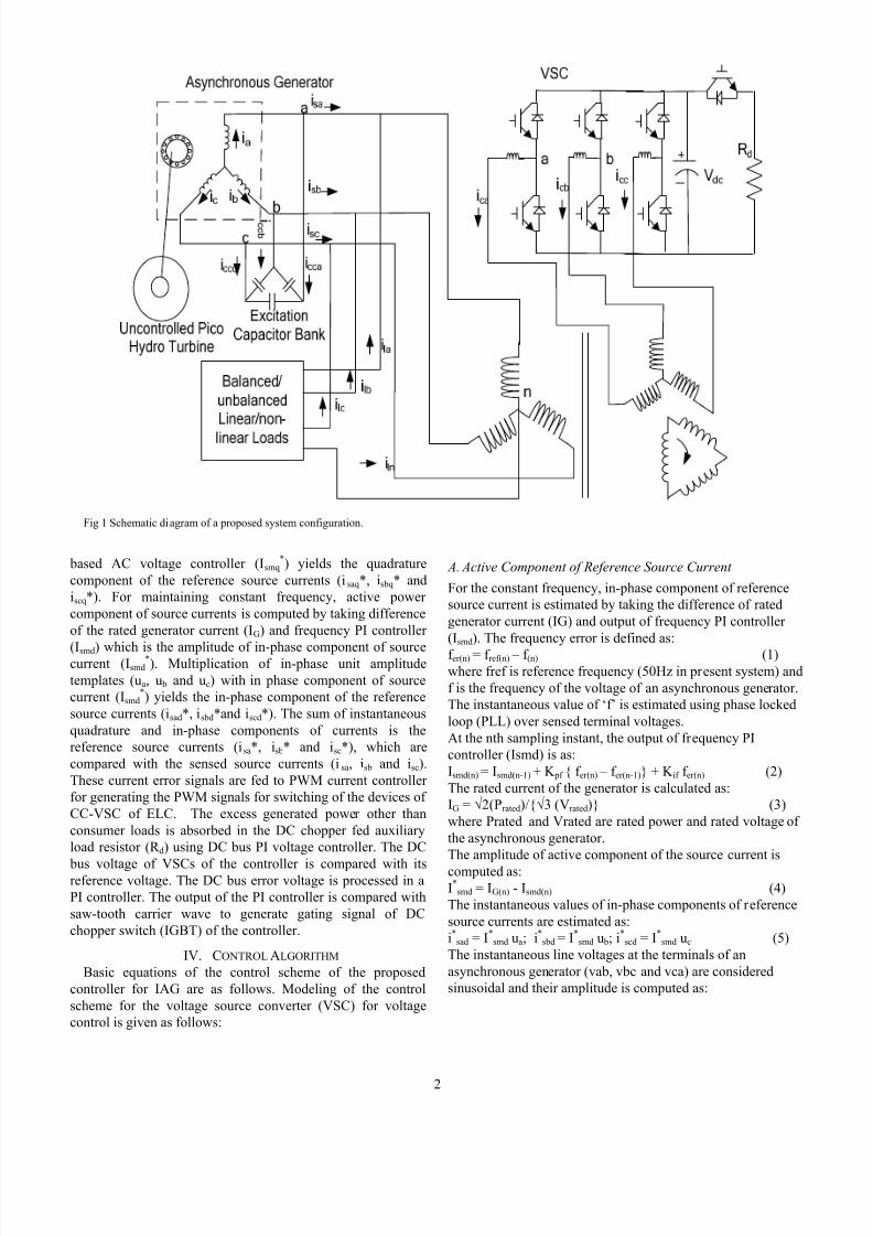
II. SYSTEM CONFIGURATION Fig 1 shows an isolated generating system along with the
proposed voltage and frequency controller. The proposedsystem consists of a squirrel cage asynchronous generator driven by uncontrolled pico hydro turbine and its controller isconnected at the point of common coupling through interfacingtransformers. A star delta transformer is used to create aneutral conductor to form four wire topology. The star deltatransformer acts as a path for zero-sequence components of load currents while VSC serves the purpose of harmonicelimination, load balancing, and reactive power compensationfor voltage control. The star delta transformer consists of three
windings transformers with the turn ratio of 2:2:1 and thecurrents in three phases of the generator are balanced andsinusoidal.
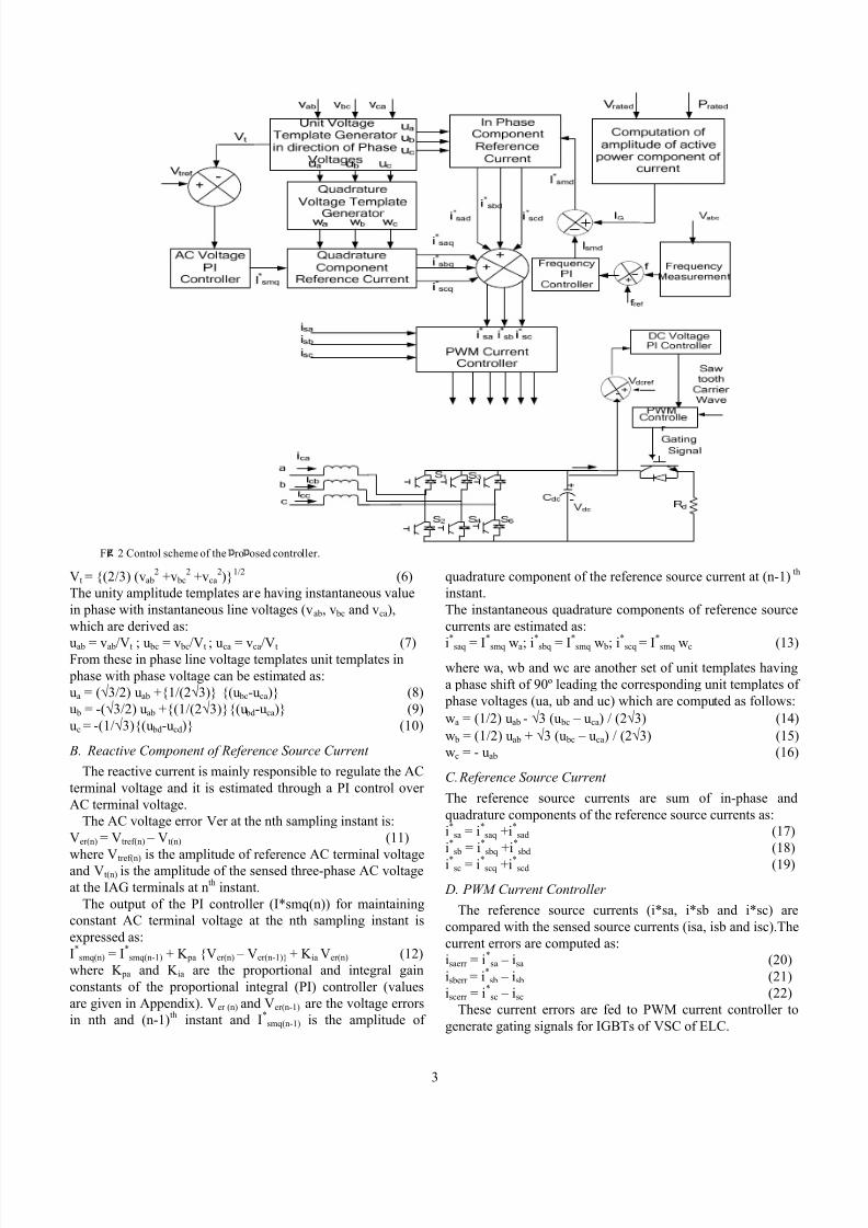
III. CONTROL STRATEGY Fig.2 shows the control scheme of the proposed controller
to regulate the voltage and frequency of the asynchronousgenerator. The control scheme is based on the generation of reference source currents which one having two componentsone is in-phase or active power component and other one is inquadrature or reactive power component. The in-phase unityamplitude templates (ua, u b and uc) are three-phase sinusoidalfunctions, which are derived by unit templates of in phase withline voltages (u
ab, u
bc, u
ca). These templates (u
ab, u
bc, u
ca) are
derived by dividing the AC line voltages vab, v bc and vca bytheir amplitude Vt. To generate the quadrature component of reference source currents, another set of sinusoidal quadratureunity amplitude templates (wa, w b, wc) is obtained from in- phase unit templates (uab, u bc, uca). To regulate AC terminalvoltage (Vt), it is sensed and compared with the referencevoltage (Vtref ). The voltage error is processed in a PI(Proportional-Integral) voltage controller. The output of the PIcontroller for AC voltage control loop decides the amplitudeof reactive current (Ismq
*). Multiplication of quadrature unityamplitude templates (wa, w b and wc) with the output of PI
VSC With Star Delta Transformer BasedElectronic Load Controller for a Stand-Alone
Power Generation
Gaurav Kumar Kasal and Bhim Singh Senior Member, IEEE
T
7/27/2019 Star Delta Trans
http://slidepdf.com/reader/full/star-delta-trans 2/62
based AC voltage controller (Ismq*) yields the quadrature
component of the reference source currents (isaq*, isbq* andiscq*). For maintaining constant frequency, active power component of source currents is computed by taking differenceof the rated generator current (IG) and frequency PI controller
(Ismd) which is the amplitude of in-phase component of sourcecurrent (Ismd*). Multiplication of in-phase unit amplitude
templates (ua, u b and uc) with in phase component of sourcecurrent (Ismd
*) yields the in-phase component of the referencesource currents (isad*, isbd*and iscd*). The sum of instantaneousquadrature and in-phase components of currents is thereference source currents (isa*, isb* and isc*), which arecompared with the sensed source currents (isa, isb and isc).These current error signals are fed to PWM current controller for generating the PWM signals for switching of the devices of CC-VSC of ELC. The excess generated power other thanconsumer loads is absorbed in the DC chopper fed auxiliaryload resistor (R d) using DC bus PI voltage controller. The DC
bus voltage of VSCs of the controller is compared with itsreference voltage. The DC bus error voltage is processed in aPI controller. The output of the PI controller is compared withsaw-tooth carrier wave to generate gating signal of DCchopper switch (IGBT) of the controller.
IV. CONTROL ALGORITHM Basic equations of the control scheme of the proposed
controller for IAG are as follows. Modeling of the controlscheme for the voltage source converter (VSC) for voltagecontrol is given as follows:
A. Active Component of Reference Source Current
For the constant frequency, in-phase component of referencesource current is estimated by taking the difference of ratedgenerator current (IG) and output of frequency PI controller (Ismd). The frequency error is defined as:
f er(n) = f ref(n) – f (n) (1)where fref is reference frequency (50Hz in present system) andf is the frequency of the voltage of an asynchronous generator.The instantaneous value of ‘f’ is estimated using phase lockedloop (PLL) over sensed terminal voltages.At the nth sampling instant, the output of frequency PIcontroller (Ismd) is as:Ismd(n) = Ismd(n-1) + K pf f er(n) – f er(n-1) + K if f er(n) (2)The rated current of the generator is calculated as:IG = √2(Prated)/√3 (Vrated) (3)where Prated and Vrated are rated power and rated voltage of the asynchronous generator.The amplitude of active component of the source current is
computed as:I*
smd = IG(n) - Ismd(n) (4)The instantaneous values of in-phase components of referencesource currents are estimated as:i*
sad = I*smd ua; i*
sbd = I*smd u b; i
*scd = I*
smd uc (5)The instantaneous line voltages at the terminals of anasynchronous generator (vab, vbc and vca) are consideredsinusoidal and their amplitude is computed as:
Fig 1 Schematic diagram of a proposed system configuration.
7/27/2019 Star Delta Trans
http://slidepdf.com/reader/full/star-delta-trans 3/63
Vt = (2/3) (vab2 +v bc
2 +vca2)1/2 (6)
The unity amplitude templates are having instantaneous valuein phase with instantaneous line voltages (vab, v bc and vca),which are derived as:
uab = vab/Vt ; u bc = v bc/Vt ; uca = vca/Vt (7)From these in phase line voltage templates unit templates in phase with phase voltage can be estimated as:ua = (√3/2) uab +1/(2√3) (u bc-uca) (8)u b = -(√3/2) uab +(1/(2√3)(u bd-uca) (9)uc = -(1/√3)(u bd-ucd) (10)
B. Reactive Component of Reference Source Current
The reactive current is mainly responsible to regulate the ACterminal voltage and it is estimated through a PI control over AC terminal voltage.
The AC voltage error Ver at the nth sampling instant is:Ver(n) = Vtref(n) – Vt(n) (11)
where Vtref(n) is the amplitude of reference AC terminal voltageand Vt(n) is the amplitude of the sensed three-phase AC voltageat the IAG terminals at nth instant.
The output of the PI controller (I*smq(n)) for maintainingconstant AC terminal voltage at the nth sampling instant isexpressed as:I*
smq(n) = I*smq(n-1) + K pa Ver(n) – Ver(n-1) + K ia Ver(n) (12)
where K pa and K ia are the proportional and integral gainconstants of the proportional integral (PI) controller (valuesare given in Appendix). Ver (n) and Ver(n-1) are the voltage errorsin nth and (n-1)th instant and I*
smq(n-1) is the amplitude of
quadrature component of the reference source current at (n-1) th instant.The instantaneous quadrature components of reference sourcecurrents are estimated as:
i*
saq = I*
smq wa; i*
sbq = I*
smq w b; i*
scq = I*
smq wc (13)where wa, wb and wc are another set of unit templates havinga phase shift of 90º leading the corresponding unit templates of phase voltages (ua, ub and uc) which are computed as follows:wa = (1/2) uab - √3 (u bc – uca) / (2√3) (14)w b = (1/2) uab + √3 (u bc – uca) / (2√3) (15)wc = - uab (16)
C. Reference Source Current
The reference source currents are sum of in-phase andquadrature components of the reference source currents as:i*
sa = i*saq +i*
sad (17)i*
sb = i*sbq +i*
sbd (18)
i*sc = i*scq +i*scd (19)
D. PWM Current Controller
The reference source currents (i*sa, i*sb and i*sc) arecompared with the sensed source currents (isa, isb and isc).Thecurrent errors are computed as:isaerr = i*
sa – isa (20)isberr = i*
sb – isb (21)iscerr = i*
sc – isc (22)These current errors are fed to PWM current controller to
generate gating signals for IGBTs of VSC of ELC.
Fi 2 Control scheme of the ro osed controller.
7/27/2019 Star Delta Trans
http://slidepdf.com/reader/full/star-delta-trans 4/64
E. Control for DC Bus Chopper
To maintain constant DC bus voltage of VSC, the DC voltageerror Vdcer(n) at nth sampling instant is calculated as:Vdcer(n) = Vdcref(n) – Vdc(n) (23)where Vdcref(n) is the reference DC voltage and Vdc(n) is thesensed DC link voltage of the CC-VSC.The output of the PI voltage controller at the nth samplinginstant is expressed as:V*
con(n) = V*con(n-1) + K pp Per(n) – Per(n-1) + K pi Per(n) (24)
where K pp and K pi are the proportional and integral gainconstants of the DC bus voltage controller. The PI controller output (V*
con(n)) is compared with the triangular carrier (V tri)waveform and output is fed to the gate of the chopper switch(IGBT) in ELC.
V. MATLAB BASED MODELING The proposed isolated generating system is modeled and
simulated in MATLAB using Simulink and PSB toolboxes.The main system consists of an asynchronous machine withexcitation capacitor bank, a star delta transformer with tertiarywinding and VSC based controller. The modeling of AGs is
carried out using a 22 kW, 415V, 50Hz, Y connectedasynchronous machine. The controller is realized with avoltage source converter and DC chopper at its DC bus. Bothlinear and non-linear loads are considered here to demonstratethe capability of the controller. Simulation is carried out indiscrete mode at 5e-6s step size with ode23tb (stiff/ TR-BDF-2) solver .
VI. R ESULTS A ND DISCUSSION The performance of voltage and frequency controller for IAG
system feeding 3-phase 4-wire non- linear, balanced/unbalanced and mixed loads is simulated andwaveforms of the generator voltages (vabc) and currents (iabc),capacitor current (icca), load currents (ilabc), controller currents(icabc), neutral current of load (iln), terminal voltage (Vt), DC bus voltage (vdc), frequency (f) and the variation of power (Pgen, Pload and Pdump) etc are shown in Figs. 3-4. For thesimulation, a 22 kW, 415V, 4 pole asynchronous machine has been used as an asynchronous generator and parameters aregiven in Appendix
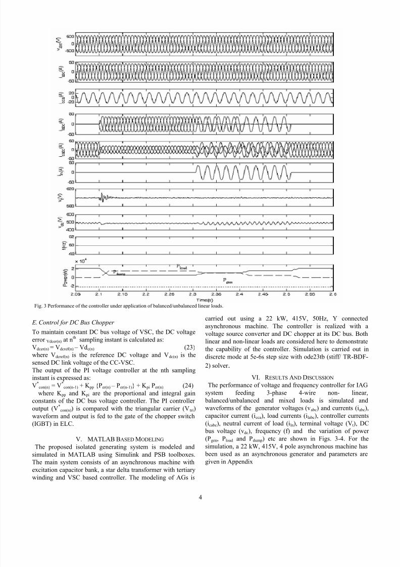
Fig. 3 Performance of the controller under application of balanced/unbalanced linear loads.
7/27/2019 Star Delta Trans
http://slidepdf.com/reader/full/star-delta-trans 5/65
A Performance of Isolated System Feeding 3-Phase 4-Wire
Linear Loads
Fig 3 demonstrates the performance of the controller for feeding 3-phase, 4- wire, 0.8 pf lagging reactive load. At 2.1 sthree single phase, 0.8 pf lagging reactive loads are applied between each phase and neutral terminal and it is observed thatmomentarily the DC bus capacitor voltage is increasedhowever due to action of the controller it is regulated at
constant value and it maintains the frequency constant. At 2.3 sone phase and later on at 2.4 s another phase of the load isopened and the load becomes unbalanced. It is observed thatthe controller responds in desirable manner and maintainingconstant voltage and frequency. It also functions as a load balancer and generator currents remain balanced andsinusoidal.
B Performance of Isolated System Feeding 3-Phase 4-Wire
Non-linear Loads
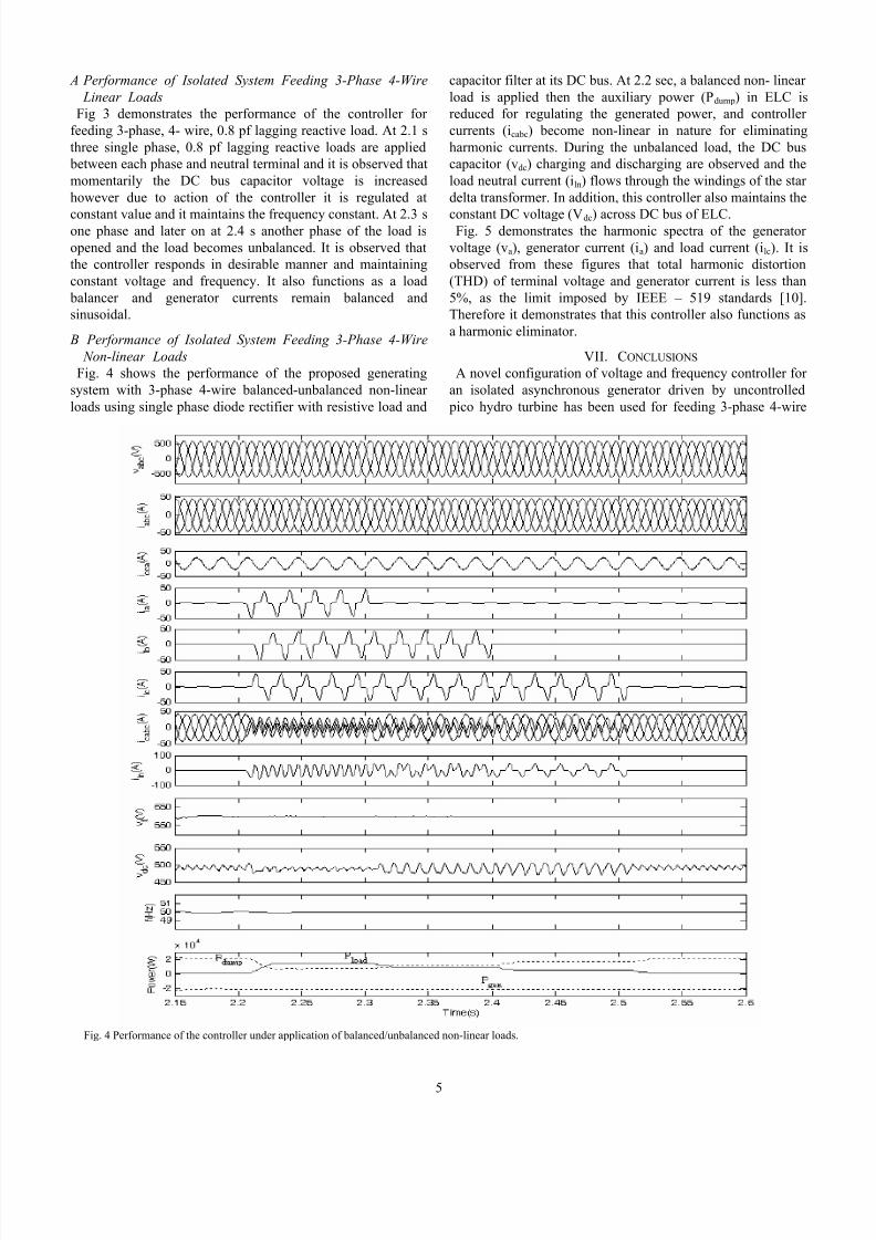
Fig. 4 shows the performance of the proposed generatingsystem with 3-phase 4-wire balanced-unbalanced non-linear loads using single phase diode rectifier with resistive load and
capacitor filter at its DC bus. At 2.2 sec, a balanced non- linear load is applied then the auxiliary power (Pdump) in ELC isreduced for regulating the generated power, and controller currents (icabc) become non-linear in nature for eliminatingharmonic currents. During the unbalanced load, the DC buscapacitor (vdc) charging and discharging are observed and theload neutral current (iln) flows through the windings of the star delta transformer. In addition, this controller also maintains the
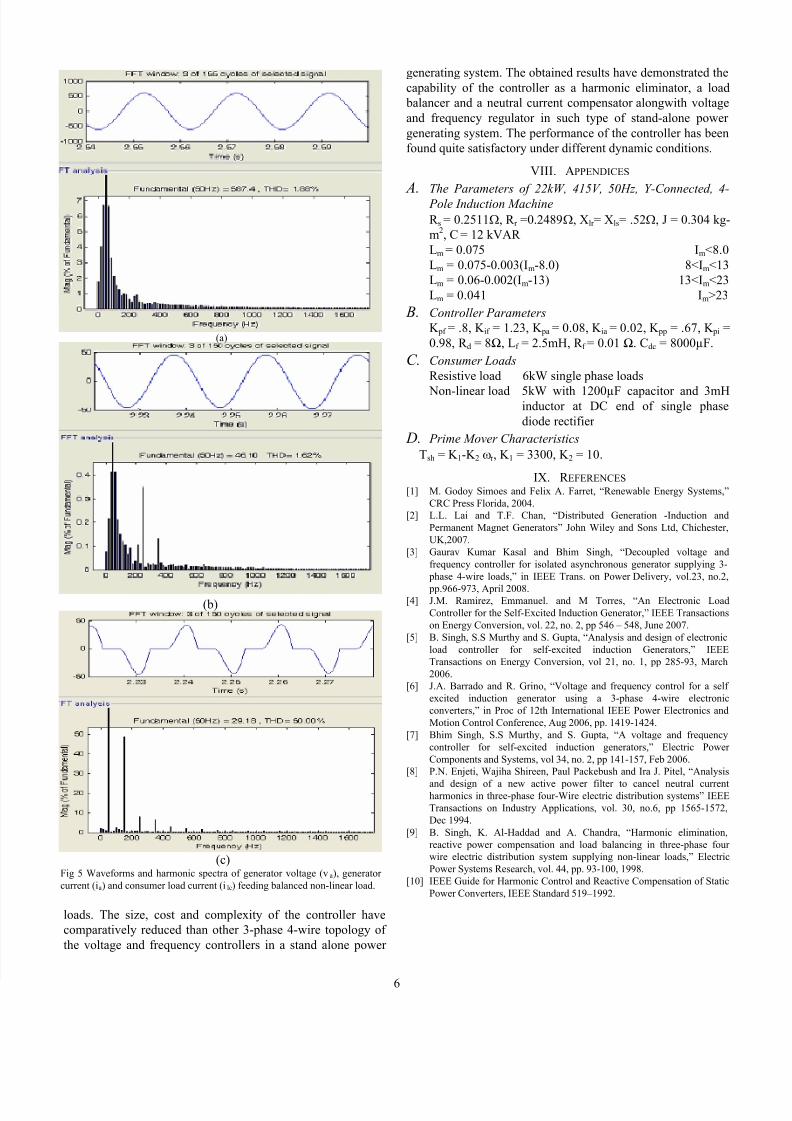
constant DC voltage (Vdc) across DC bus of ELC.Fig. 5 demonstrates the harmonic spectra of the generator voltage (va), generator current (ia) and load current (ilc). It isobserved from these figures that total harmonic distortion(THD) of terminal voltage and generator current is less than5%, as the limit imposed by IEEE – 519 standards [10].Therefore it demonstrates that this controller also functions asa harmonic eliminator.
VII. CONCLUSIONS A novel configuration of voltage and frequency controller for
an isolated asynchronous generator driven by uncontrolled pico hydro turbine has been used for feeding 3-phase 4-wire
Fig. 4 Performance of the controller under application of balanced/unbalanced non-linear loads.
7/27/2019 Star Delta Trans
http://slidepdf.com/reader/full/star-delta-trans 6/66
loads. The size, cost and complexity of the controller havecomparatively reduced than other 3-phase 4-wire topology of the voltage and frequency controllers in a stand alone power
generating system. The obtained results have demonstrated thecapability of the controller as a harmonic eliminator, a load balancer and a neutral current compensator alongwith voltageand frequency regulator in such type of stand-alone power generating system. The performance of the controller has beenfound quite satisfactory under different dynamic conditions.
VIII. APPENDICES A. The Parameters of 22kW, 415V, 50Hz, Y-Connected, 4-
Pole Induction Machine
R s = 0.2511Ω, R r =0.2489Ω, Xlr = Xls= .52Ω, J = 0.304 kg-m2, C = 12 kVAR Lm = 0.075 Im<8.0Lm = 0.075-0.003(Im-8.0) 8<Im<13Lm = 0.06-0.002(Im-13) 13<Im<23Lm = 0.041 Im>23
B. Controller Parameters
K pf = .8, K if = 1.23, K pa = 0.08, K ia = 0.02, K pp = .67, K pi =0.98, R d = 8Ω, Lf = 2.5mH, R f = 0.01 Ω. Cdc = 8000µF.
C. Consumer Loads
Resistive load 6kW single phase loads
Non-linear load 5kW with 1200µF capacitor and 3mHinductor at DC end of single phasediode rectifier
D. Prime Mover Characteristics
Tsh = K 1-K 2 ωr , K 1 = 3300, K 2 = 10.
IX. R EFERENCES [1] M. Godoy Simoes and Felix A. Farret, “Renewable Energy Systems,”
CRC Press Florida, 2004.[2] L.L. Lai and T.F. Chan, “Distributed Generation -Induction and
Permanent Magnet Generators” John Wiley and Sons Ltd, Chichester,UK,2007.
[3] Gaurav Kumar Kasal and Bhim Singh, “Decoupled voltage andfrequency controller for isolated asynchronous generator supplying 3-
phase 4-wire loads,” in IEEE Trans. on Power Delivery, vol.23, no.2,
pp.966-973, April 2008.[4] J.M. Ramirez, Emmanuel. and M Torres, “An Electronic LoadController for the Self-Excited Induction Generator,” IEEE Transactionson Energy Conversion, vol. 22, no. 2, pp 546 – 548, June 2007.
[5] B. Singh, S.S Murthy and S. Gupta, “Analysis and design of electronicload controller for self-excited induction Generators,” IEEETransactions on Energy Conversion, vol 21, no. 1, pp 285-93, March2006.
[6] J.A. Barrado and R. Grino, “Voltage and frequency control for a self excited induction generator using a 3-phase 4-wire electronicconverters,” in Proc of 12th International IEEE Power Electronics andMotion Control Conference, Aug 2006, pp. 1419-1424.
[7] Bhim Singh, S.S Murthy, and S. Gupta, “A voltage and frequencycontroller for self-excited induction generators,” Electric Power Components and Systems, vol 34, no. 2, pp 141-157, Feb 2006.
[8] P.N. Enjeti, Wajiha Shireen, Paul Packebush and Ira J. Pitel, “Analysis
and design of a new active power filter to cancel neutral currentharmonics in three-phase four-Wire electric distribution systems” IEEETransactions on Industry Applications, vol. 30, no.6, pp 1565-1572,Dec 1994.
[9] B. Singh, K. Al-Haddad and A. Chandra, “Harmonic elimination,reactive power compensation and load balancing in three-phase four wire electric distribution system supplying non-linear loads,” ElectricPower Systems Research, vol. 44, pp. 93-100, 1998.
[10] IEEE Guide for Harmonic Control and Reactive Compensation of StaticPower Converters, IEEE Standard 519–1992.
(a)
(b)
(c)Fig 5 Waveforms and harmonic spectra of generator voltage (va), generator current (ia) and consumer load current (i lc) feeding balanced non-linear load.