
Multi-User Augmented Reality with Communication Efficient ...
13
Multi-User Augmented Reality with Communication Eficient and Spatially Consistent Virtual Objects Xukan Ran Computer Science & Engineering University of California, Riverside Riverside, CA, USA [email protected] Carter Slocum Computer Science & Engineering University of California, Riverside Riverside, CA, USA [email protected] Yi-Zhen Tsai Computer Science & Engineering University of California, Riverside Riverside, CA, USA [email protected] Kittipat Apicharttrisorn Computer Science & Engineering University of California, Riverside Riverside, CA, USA [email protected] Maria Gorlatova Electrical & Computer Engineering Duke University Durham, NC, USA [email protected] Jiasi Chen Computer Science & Engineering University of California, Riverside Riverside, CA, USA [email protected] Abstract Multi-user augmented reality (AR), where multiple co-located users view a common set of virtual objects, is becoming increas- ingly popular. For example, Google Just a Line allows multiple users to draw virtual grafti in the same physical space. Multi-user AR requires network communications in order to coordinate the positions of the virtual objects on each user’s display, yet there is currently little understanding of how such apps communicate. In this work, we address this key gap in knowledge by showing that the communicated data directly impacts the latency and posi- tioning of the virtual objects rendered on the users’ displays. We develop solutions to these problems that we fnd along three facets: (1) efcient communication strategies that trade of communica- tion latency for spatial consistency of the virtual objects; (2) a new metric that enables mobile AR devices to update their virtual ob- jects as they move around and observe more of the scene; and (3) a tool to automatically quantify how much the virtual objects’ po- sitions inadvertently change in time and space. Our evaluation is performed on Android smartphones running open-source AR. The results show that our system, SPAR, can decrease the latency by up to 55%, while decreasing the spatial inconsistency by up to 60%, compared to baseline methods. CCS Concepts · Human-centered computing → Ubiquitous and mobile comput- ing; · Networks; · Information systems → Multimedia infor- mation systems; Keywords Augmented reality, multi-user AR, latency, spatial inconsistency Permission to make digital or hard copies of part or all of this work for personal or classroom use is granted without fee provided that copies are not made or distributed for proft or commercial advantage and that copies bear this notice and the full citation on the frst page. Copyrights for third-party components of this work must be honored. For all other uses, contact the owner/author(s). CoNEXT ’20, December 1ś4, 2020, Barcelona, Spain © 2020 Copyright held by the owner/author(s). ACM ISBN 978-1-4503-7948-9/20/12. https://doi.org/10.1145/3386367.3431312 ACM Reference Format: Xukan Ran, Carter Slocum, Yi-Zhen Tsai, Kittipat Apicharttrisorn, Maria Gorlatova, and Jiasi Chen. 2020. Multi-User Augmented Reality with Com- munication Efcient and Spatially Consistent Virtual Objects. In The 16th International Conference on emerging Networking EXperiments and Technolo- gies (CoNEXT ’20), December 1ś4, 2020, Barcelona, Spain. ACM, New York, NY, USA, 13 pages. https://doi.org/10.1145/3386367.3431312 1 Introduction Augmented Reality (AR) applications have recently exploded in popularity among smartphone users. In AR, a user’s feld-of- view (FoV) is overlaid with virtual objects, which should remain fxed with respect to the real world in order to provide a seamless transition between the real world and the virtual objects. As AR becomes more popular, a natural question is: can we share the vir- tual objects with other users? Based on the of-the-shelf AR apps currently available, the answer is łyesž. For example, Pokemon Go released the Buddy Adventures feature in December 2019, which allows multiple users to view their virtual creatures together in the same real world space. Other multi-user AR applications currently available include Just a Line, where multiple users can collabora- tively draw virtual grafti, and Minecraft, where users can build structures together from virtual blocks. Yet despite their emerging popularity, little is known about the network communications of multi-user AR apps. The fact that these apps involve multiple users clearly indicates that some form of net- work communication is required. However, it is currently unknown how these apps communicate, what they are communicating, and how the data communications impact user experience. This work seeks to address this key gap in knowledge, and propose solutions to the problems that we fnd in this space. Through our measurements of of-the-shelf multi-user AR apps (detailed in Sec. 2), we fnd that users experience multiple seconds of latency between one user placing a virtual object to it appearing on another user’s display. Moreover, the virtual objects can appear at diferent locations, with respect to the real world, on each user’s display. These two problems ś latency and spatial inconsistency ś are key factors in AR user experience [13, 29, 51], and we fnd that they depend on the communicated information between the AR devices. Thus the goal of this work is to optimize the network
Transcript of Multi-User Augmented Reality with Communication Efficient ...
Multi-User Augmented Reality with Communication Efficientand Spatially Consistent Virtual Objects
Xukan RanComputer Science & EngineeringUniversity of California, Riverside
Riverside, CA, [email protected]
Carter SlocumComputer Science & EngineeringUniversity of California, Riverside
Riverside, CA, [email protected]
Yi-Zhen TsaiComputer Science & EngineeringUniversity of California, Riverside
Riverside, CA, [email protected]
Kittipat ApicharttrisornComputer Science & EngineeringUniversity of California, Riverside
Riverside, CA, [email protected]
Maria GorlatovaElectrical & Computer Engineering
Duke UniversityDurham, NC, USA
Jiasi ChenComputer Science & EngineeringUniversity of California, Riverside
Riverside, CA, [email protected]
Abstract
Multi-user augmented reality (AR), where multiple co-located
users view a common set of virtual objects, is becoming increas-
ingly popular. For example, Google Just a Line allows multiple
users to draw virtual graffiti in the same physical space. Multi-user
AR requires network communications in order to coordinate the
positions of the virtual objects on each user’s display, yet there
is currently little understanding of how such apps communicate.
In this work, we address this key gap in knowledge by showing
that the communicated data directly impacts the latency and posi-
tioning of the virtual objects rendered on the users’ displays. We
develop solutions to these problems that we find along three facets:
(1) efficient communication strategies that trade off communica-
tion latency for spatial consistency of the virtual objects; (2) a new
metric that enables mobile AR devices to update their virtual ob-
jects as they move around and observe more of the scene; and (3)
a tool to automatically quantify how much the virtual objects’ po-
sitions inadvertently change in time and space. Our evaluation is
performed on Android smartphones running open-source AR. The
results show that our system, SPAR, can decrease the latency by
up to 55%, while decreasing the spatial inconsistency by up to 60%,
compared to baseline methods.
CCS Concepts
·Human-centered computing→ Ubiquitous and mobile comput-
ing; · Networks; · Information systems→Multimedia infor-
mation systems;
KeywordsAugmented reality, multi-user AR, latency, spatial inconsistency
Permission to make digital or hard copies of part or all of this work for personal orclassroom use is granted without fee provided that copies are not made or distributedfor profit or commercial advantage and that copies bear this notice and the full citationon the first page. Copyrights for third-party components of this work must be honored.For all other uses, contact the owner/author(s).
CoNEXT ’20, December 1ś4, 2020, Barcelona, Spain
© 2020 Copyright held by the owner/author(s).ACM ISBN 978-1-4503-7948-9/20/12.https://doi.org/10.1145/3386367.3431312
ACM Reference Format:
Xukan Ran, Carter Slocum, Yi-Zhen Tsai, Kittipat Apicharttrisorn, Maria
Gorlatova, and Jiasi Chen. 2020. Multi-User Augmented Reality with Com-
munication Efficient and Spatially Consistent Virtual Objects. In The 16th
International Conference on emerging Networking EXperiments and Technolo-
gies (CoNEXT ’20), December 1ś4, 2020, Barcelona, Spain. ACM, New York,
NY, USA, 13 pages. https://doi.org/10.1145/3386367.3431312
1 Introduction
Augmented Reality (AR) applications have recently exploded
in popularity among smartphone users. In AR, a user’s field-of-
view (FoV) is overlaid with virtual objects, which should remain
fixed with respect to the real world in order to provide a seamless
transition between the real world and the virtual objects. As AR
becomes more popular, a natural question is: can we share the vir-
tual objects with other users? Based on the off-the-shelf AR apps
currently available, the answer is łyesž. For example, Pokemon Go
released the Buddy Adventures feature in December 2019, which
allows multiple users to view their virtual creatures together in the
same real world space. Other multi-user AR applications currently
available include Just a Line, where multiple users can collabora-
tively draw virtual graffiti, and Minecraft, where users can build
structures together from virtual blocks.
Yet despite their emerging popularity, little is known about the
network communications of multi-user AR apps. The fact that these
apps involve multiple users clearly indicates that some form of net-
work communication is required. However, it is currently unknown
how these apps communicate, what they are communicating, and
how the data communications impact user experience. This work
seeks to address this key gap in knowledge, and propose solutions
to the problems that we find in this space.
Through our measurements of off-the-shelf multi-user AR apps
(detailed in Sec. 2), we find that users experience multiple seconds
of latency between one user placing a virtual object to it appearing
on another user’s display. Moreover, the virtual objects can appear
at different locations, with respect to the real world, on each user’s
display. These two problems ś latency and spatial inconsistency
ś are key factors in AR user experience [13, 29, 51], and we find
that they depend on the communicated information between the
AR devices. Thus the goal of this work is to optimize the network
CoNEXT ’20, December 1ś4, 2020, Barcelona, Spain Ran et al.
communications of multi-user AR apps, to enable fast and accurate
coordination of the virtual objects across AR displays. For example,
in a classroom, students equipped with AR devices should be able to
see the same virtual chemistry molecule and manipulate it, with the
virtual molecule remaining consistent across students. However,
uncoordinated or laggy updates to the virtual molecule would break
the illusion of seamless integration with the real world, and result
in artifacts such as other users appearing to touch non-existent
parts of the virtual molecule.
We meet and address several technical challenges towards real-
izing this vision. (1) Firstly, multi-user AR apps share a large initial
data burst containing information about the real world environ-
ment, in order to render the virtual objects at the correct locations
on each AR display. This leads to multiple seconds of latency when-
ever users move to a new area and wait for virtual objects to appear.
To address this, we propose communication strategies that adapt to
the positions of the virtual objects in order to reduce communication
latency. (2) Next, as the user moves around, the AR device con-
tinuously observes new information about the real world. These
observations can be processed to update the virtual objects’ posi-
tions with respect to the real world, but the update may actually
harm the positioning accuracy if the wrong information is used.
To address this, we propose a new łfeature geo distancež metric that
allows the AR app to select the right camera frames to re-align the
virtual objects’ positions with other users. (3) Finally, multi-user AR
apps do not know if their virtual objects are drifting in time or in
space. Without knowing that the virtual objects are experiencing
positioning issues, these apps does not know when problems need
to be corrected. To address this, we develop a methodology and tool
to automatically quantify spatial inconsistency issues of the virtual
object across time and across users.
While there has been research on object detection and cloud/edge
offloading for AR (e.g., [27, 32, 42]), these works typically consider
a single user viewing the virtual objects, rather than multi-user co-
ordination. They also do not incorporate simultaneous localization
and mapping (SLAM), which is part of off-the-shelf AR systems
today to enable 3D understanding, but contribute to the latency and
spatial inconsistency issues that we observe. Industry players have
started to look at multi-user AR [8, 20, 35], but focus mainly on
application development and not the communication aspects of the
underlying platform. To the best of our knowledge, no prior work
has systematically examined AR spatial consistency issues when
there are multiple users, and their dependency on the network data
transmissions between the devices.
In summary, we study the emerging application of multi-user
AR and its networking aspects. In particular, we focus on rendering
virtual objects that are clustered around a common łanchorž point
in the real world [20]; this is common in typical multi-user AR
apps (e.g., all the virtual Pokemon or virtual graffiti are placed near
each other). We call our system SPAR (SPatially Consistent AR). Our
contributions include:
• We measure the performance and network usage of off-the-shelf
AR apps, and identify problems of high latency, spatial drift, and
spatial inconsistency of the virtual objects over time and across
users.
x
y
z
xy
zx
y
z
<(-15,0,-1), 15°>
<(17,0,3), 17°>
<(1,0,10), 12°>
device A
device B
device C
Virtual object
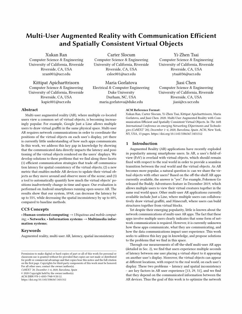
Figure 1: Multiple AR devices try to ensure consistent views
of a virtual object, despite different coordinate systems.
• We develop new methods for efficient communication and com-
putation of the AR devices. Specifically, SPAR performs the fol-
lowing: (i) it adapts the communicated information to the virtual
object positions, to reduce latency; (ii) it efficiently computes the
virtual objects’ positions in each user’s display through light-
weight coordinate system alignment, to create spatial consis-
tency; (iii) it continuously updates the positions of the virtual
objects with respect to the real world using a new update metric,
to maintain spatial consistency; and (iv) it automatically quan-
tifies the spatial drift and consistency of the virtual objects, to
evaluate performance.
• Weperform evaluation onAndroidAR devices, extending VINS [31],
a 6DoF-based AR platform, with multi-user capabilities. We work
with open-source systems because existing AR platforms from
Android, Apple, and Microsoft [8, 20, 35] are closed source and
thus their internal code cannot be modified for experimentation.
Our results show that SPAR can decrease the total latency by up
to 55%, while decreasing the spatial inconsistency of the virtual
objects by up to 60%, compared to a baseline method of com-
municating the full data or off-the-shelf AR platforms. We also
show that our tool can estimate a virtual object’s spatial drift
and inconsistency with a low RMSE of only 0.92 cm, compared
to manual human labeling.
In the remainder of this paper, we discuss the measurements that
motivate this work (Sec. 2), a brief background (Sec. 3), the over-
all system architecture (Sec. 4), and the design of the individual
components (Sec. 5). We then evaluate the system (Sec. 7), discuss
related work (Sec. 9), then conclude (Sec. 10).
2 Motivation: Spatial Drift, Inconsistency, and
Latency of Off-the-Shelf Mobile ARTo showcase the issues of virtual object spatial inconsistency
and latency in multi-user AR, we examined several off-the-shelf
AR Android apps. The four Android apps we tried were Google
CloudAnchor [20], Google Just a Line [21], Minecraft [37], and
Pokemon Go [39], running on Pixel 4 smartphones. We have two
users, Alice and Bob, who perform the following sequence of user
interactions:
(1) Place initial virtual object: Alice places a virtual object by
tapping the screen.
Multi-User AR with Communication Efficient and Spatially Consistent Virtual Objects CoNEXT ’20, December 1ś4, 2020, Barcelona, Spain
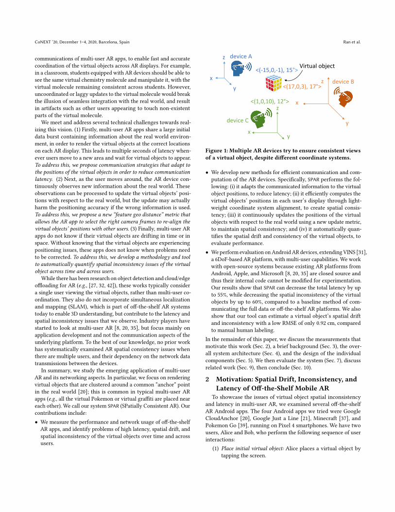
Alice’s view: Bob’s view:
(a) Spatial inconsistency across two AR devices.
Small Area Large Area
Sp
atia
l D
rift
(cm
)
0
2
4
6
VINS-AR ARCore
(b) Spatial drift (c) Spatial inconsistency
Figure 2: Quantifying spatial drift and inconsistency. The resolving devices suffer from spatial drift of 2-4 cm and fail to resolve
if their orientation with respect to the host is more than 60◦.
(2) Render initial virtual object: Bob waits for it to appear on his
screen.
(3) Subsequent user interactions: Alice taps the screen to move a
virtual object or place new virtual objects (only Just a Line
and Minecraft have this feature). Bob waits for the update
to be reflected on his screen.
Our main finding is that there is significant delay and spatial in-
consistency between when Alice places the first virtual object and
Bob renders it on the screen (steps 1 and 2 above), thus motivating
the work in this paper. Similar results hold when there are multiple
receiving users (i.e.,multiple Bobs) who wish to view Alice’s virtual
objects. Below, we detail our quantitative measurements.
Spatial drift and inconsistency: We experimented 5 times
with CloudAnchor, with each trial lasting 1minutewith Bobmoving
1 m (small area) to 4 m (large area) in the real world. In these
experiments, we observed two types of spatial issues relating to
the virtual object’s position:
• Spatial drift: For a single user, the virtual object can drift in
position over time.
• Spatial inconsistency: When there are multiple users, the virtual
object can appear in a different location, relative to the real world,
on each user’s display, as shown in Fig. 2a.
In the single-user case (Fig. 2b), the spatial drift is around 2-3 cm
in both the large and small areas, for both ARCore [19] and VINS-
AR [31] platforms. In the multi-user case, spatial inconsistency
results are larger (results later in Sec. 7), and moreover we observe
that when the two devices are placed more than 60◦ apart, the
virtual object fails to resolve, as shown in Fig. 2c. We also observed
similar issues with Magic Leap, but focus on smartphone-based
AR in this work due to the ubiquity of smartphone devices. These
spatial drift, inconsistency, or failure to resolve a virtual object can
cause serious issues when multiple users interact in a shared AR
session (e.g., multiple users jointly building a tower of building
blocks), and are key contributors to user experience in AR [29, 51].
This motivates SPAR’s goal of reducing spatial drift and inconsis-
tency. Similar to prior work [47], we focus on positioning errors, as
we did not observe much rotational error our experiments. The low
rotational error we observe may be due to our use of visual-inertial
SLAM as the basis for our AR system, which generally has less
rotational error than pure visual SLAM [28].
Additionally, from running these experiments, we found that
manually measuring the position of the virtual object is laborious
and time-consuming, with each measurement requiring several
seconds per frame for a human to examine the image and record
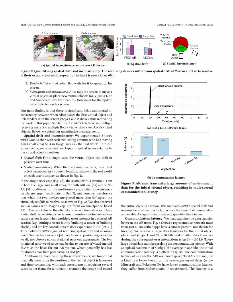
(a) Just a Line network trace.
(b) Communication latency.
Figure 3: AR apps transmit a large amount of environment
data for the initial virtual object, resulting in mult-second
communication latency.
the virtual object’s position. This motivates SPAR’s spatial drift and
inconsistency estimation tool, to reduce the amount of human labor
and enable AR apps to automatically quantify these issues.
Communication latency:We next examine the data transfer
between the AR users. Fig. 3 shows a representative network trace
from Just a Line (other apps have a similar pattern, not shown for
brevity). We observe a large data transfers for the initial object
placement (steps 1 and 2), 9-20 Mb, and smaller data transfers
during the subsequent user interactions (step 3), <100 kb. These
large initial data transfers prolong the communication latency.With
an upload bandwidth of 8 Mbps (the average in our lab), the initial
communication latency is plotted in Fig. 3b. The communication
latency of >2 s for the ARCore-based apps (CloudAnchor and Just
a Line) is a lower bound on the user-experienced delay (while
Minecraft and Pokemon Go have lower communication latency,
they suffer from higher spatial inconsistency). This latency is a
CoNEXT ’20, December 1ś4, 2020, Barcelona, Spain Ran et al.
key contributor to user experience in multi-user AR [13, 51], thus
motivating SPAR’s goal of reducing user-perceived latency.
Connection between latency and spatial inconsistency:We
discover there is a critical connection between the aforementioned
spatial inconsistency and latency issues we observed. Off-the-shelf
AR platforms use similar methods [8, 20, 35] to share real world en-
vironment information between users during step 1, resulting in the
large spikes of data observed in Fig. 3. This environmental informa-
tion helps align the coordinate systems of the AR devices, enabling
each device to render the virtual objects at fixed positions in the real
world. In other words, the data communicated during the placement
of the initial virtual object (step 1) directly impacts the spatial drift
and inconsistency. This motivates SPAR’s communication-efficient
strategies to decrease communication latency, while trading off
with spatial drift and inconsistency.
3 Brief Background on ARCurrent AR platforms such as Google ARCore, Apple ARKit, and
Microsoft Hololens rely on simultaneous localization and mapping
(SLAM). SLAM solves the problem of when a device is in an un-
known environment, how to build a consistent map and localize
itself at the same time [15]. In a typical single-user AR scenario,
the AR device uses SLAM to construct a point cloud representing
the 3D coordinates of features in the real world, and also estimates
its own location and orientation (known as pose). To compute the
point cloud, SLAM selects a subset of camera frames (known as
keyframes), extracts features from the keyframes, runs SLAM al-
gorithms on the features, and outputs the 3D coordinates of the
features in each keyframe (i.e., the point cloud) and the estimated de-
vice pose. These SLAM algorithms includes keyframe matching to
localize the device with respect to its past trajectory. Each keyframe
data structure contains feature descriptors, 2D feature coordinates
with respect to the camera image, and 3D feature coordinates with
respect to the real world. The 3D feature coordinates are relative to
an origin point in the real world, which is called the device’s world
coordinate system.
To render virtual objects for AR, the device records the pose of
the virtual object (defined as its location and orientation, which
can be provided by user input or by an object detector). The AR
device runs SLAM continuously to update its own pose estimate
and the 3D coordinates of the features in the point cloud, and then
draws the virtual object on the display when its FoV overlaps with
the virtual object’s pose.
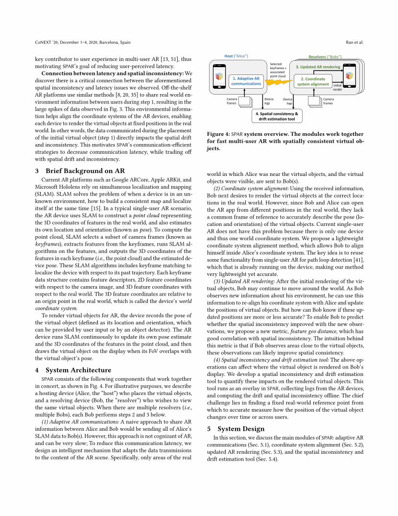
4 System ArchitectureSPAR consists of the following components that work together
in concert, as shown in Fig. 4. For illustrative purposes, we describe
a hosting device (Alice, the łhostž) who places the virtual objects,
and a resolving device (Bob, the łresolverž) who wishes to view
the same virtual objects. When there are multiple resolvers (i.e.,
multiple Bobs), each Bob performs steps 2 and 3 below.
(1) Adaptive AR communications: A naive approach to share AR
information between Alice and Bob would be sending all of Alice’s
SLAM data to Bob(s). However, this approach is not cognizant of AR,
and can be very slow; To reduce this communication latency, we
design an intelligent mechanism that adapts the data transmissions
to the content of the AR scene. Specifically, only areas of the real
Host (“Alice”) Resolvers (“Bobs”)
3. Updated AR rendering
Initial
render
Selected
keyframes +
associated
point cloud
Camera
frames
4. Spatial consistency &
drift estimation tool
1. Adaptive AR
communications
2. Coordinate
system alignment
Camera
frames
Device
logs
Device
logs
Figure 4: SPAR system overview. The modules work together
for fast multi-user AR with spatially consistent virtual ob-
jects.
world in which Alice was near the virtual objects, and the virtual
objects were visible, are sent to Bob(s).
(2) Coordinate system alignment: Using the received information,
Bob next desires to render the virtual objects at the correct loca-
tions in the real world. However, since Bob and Alice can open
the AR app from different positions in the real world, they lack
a common frame of reference to accurately describe the pose (lo-
cation and orientation) of the virtual objects. Current single-user
AR does not have this problem because there is only one device
and thus one world coordinate system. We propose a lightweight
coordinate system alignment method, which allows Bob to align
himself inside Alice’s coordinate system. The key idea is to reuse
some functionality from single-user AR for path loop detection [41],
which that is already running on the device, making our method
very lightweight yet accurate.
(3) Updated AR rendering: After the initial rendering of the vir-
tual objects, Bob may continue to move around the world. As Bob
observes new information about his environment, he can use this
information to re-align his coordinate systemwith Alice and update
the positions of virtual objects. But how can Bob know if these up-
dated positions are more or less accurate? To enable Bob to predict
whether the spatial inconsistency improved with the new obser-
vations, we propose a new metric, feature geo distance, which has
good correlation with spatial inconsistency. The intuition behind
this metric is that if Bob observes areas close to the virtual objects,
these observations can likely improve spatial consistency.
(4) Spatial inconsistency and drift estimation tool: The above op-
erations can affect where the virtual object is rendered on Bob’s
display. We develop a spatial inconsistency and drift estimation
tool to quantify these impacts on the rendered virtual objects. This
tool runs as an overlay in SPAR, collecting logs from the AR devices,
and computing the drift and spatial inconsistency offline. The chief
challenge lies in finding a fixed real-world reference point from
which to accurate measure how the position of the virtual object
changes over time or across users.
5 System DesignIn this section, we discuss the mainmodules of SPAR: adaptive AR
communications (Sec. 5.1), coordinate system alignment (Sec. 5.2),
updated AR rendering (Sec. 5.3), and the spatial inconsistency and
drift estimation tool (Sec. 5.4).
Multi-User AR with Communication Efficient and Spatially Consistent Virtual Objects CoNEXT ’20, December 1ś4, 2020, Barcelona, Spain
Host
Virtual
object
Keyframes
SPAR-LargeSPAR-Small
...
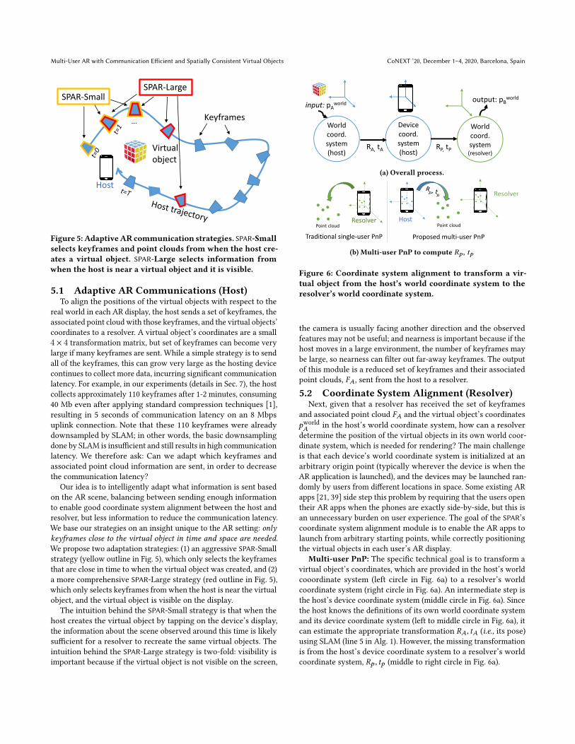
Figure 5: AdaptiveARcommunication strategies. SPAR-Small
selects keyframes and point clouds from when the host cre-
ates a virtual object. SPAR-Large selects information from
when the host is near a virtual object and it is visible.
5.1 Adaptive AR Communications (Host)To align the positions of the virtual objects with respect to the
real world in each AR display, the host sends a set of keyframes, the
associated point cloud with those keyframes, and the virtual objects’
coordinates to a resolver. A virtual object’s coordinates are a small
4 × 4 transformation matrix, but set of keyframes can become very
large if many keyframes are sent. While a simple strategy is to send
all of the keyframes, this can grow very large as the hosting device
continues to collect more data, incurring significant communication
latency. For example, in our experiments (details in Sec. 7), the host
collects approximately 110 keyframes after 1-2 minutes, consuming
40 Mb even after applying standard compression techniques [1],
resulting in 5 seconds of communication latency on an 8 Mbps
uplink connection. Note that these 110 keyframes were already
downsampled by SLAM; in other words, the basic downsampling
done by SLAM is insufficient and still results in high communication
latency. We therefore ask: Can we adapt which keyframes and
associated point cloud information are sent, in order to decrease
the communication latency?
Our idea is to intelligently adapt what information is sent based
on the AR scene, balancing between sending enough information
to enable good coordinate system alignment between the host and
resolver, but less information to reduce the communication latency.
We base our strategies on an insight unique to the AR setting: only
keyframes close to the virtual object in time and space are needed.
We propose two adaptation strategies: (1) an aggressive SPAR-Small
strategy (yellow outline in Fig. 5), which only selects the keyframes
that are close in time to when the virtual object was created, and (2)
a more comprehensive SPAR-Large strategy (red outline in Fig. 5),
which only selects keyframes from when the host is near the virtual
object, and the virtual object is visible on the display.
The intuition behind the SPAR-Small strategy is that when the
host creates the virtual object by tapping on the device’s display,
the information about the scene observed around this time is likely
sufficient for a resolver to recreate the same virtual objects. The
intuition behind the SPAR-Large strategy is two-fold: visibility is
important because if the virtual object is not visible on the screen,
yWorld coord. system (resolver)
Device coord. system (host)
World coord. system (host)
output: pBworld
input: pAworld
RP, tPRA, tA
(a) Overall process.
Resolver
Resolver
Host
Traditional single-user PnP Proposed multi-user PnPPoint cloud Point cloud
(b) Multi-user PnP to compute Rp, tp
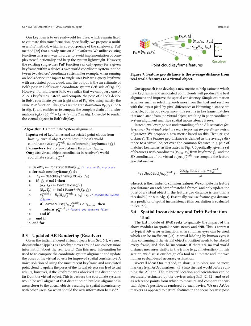
Figure 6: Coordinate system alignment to transform a vir-
tual object from the host’s world coordinate system to the
resolver’s world coordinate system.
the camera is usually facing another direction and the observed
features may not be useful; and nearness is important because if the
host moves in a large environment, the number of keyframes may
be large, so nearness can filter out far-away keyframes. The output
of this module is a reduced set of keyframes and their associated
point clouds, FA, sent from the host to a resolver.
5.2 Coordinate System Alignment (Resolver)Next, given that a resolver has received the set of keyframes
and associated point cloud FA and the virtual object’s coordinates
pworldA
in the host’s world coordinate system, how can a resolver
determine the position of the virtual objects in its own world coor-
dinate system, which is needed for rendering? The main challenge
is that each device’s world coordinate system is initialized at an
arbitrary origin point (typically wherever the device is when the
AR application is launched), and the devices may be launched ran-
domly by users from different locations in space. Some existing AR
apps [21, 39] side step this problem by requiring that the users open
their AR apps when the phones are exactly side-by-side, but this is
an unnecessary burden on user experience. The goal of the SPAR’s
coordinate system alignment module is to enable the AR apps to
launch from arbitrary starting points, while correctly positioning
the virtual objects in each user’s AR display.
Multi-user PnP: The specific technical goal is to transform a
virtual object’s coordinates, which are provided in the host’s world
cooordinate system (left circle in Fig. 6a) to a resolver’s world
coordinate system (right circle in Fig. 6a). An intermediate step is
the host’s device coordinate system (middle circle in Fig. 6a). Since
the host knows the definitions of its own world coordinate system
and its device coordinate system (left to middle circle in Fig. 6a), it
can estimate the appropriate transformation RA, tA (i.e., its pose)
using SLAM (line 5 in Alg. 1). However, the missing transformation
is from the host’s device coordinate system to a resolver’s world
coordinate system, Rp , tp (middle to right circle in Fig. 6a).
CoNEXT ’20, December 1ś4, 2020, Barcelona, Spain Ran et al.
Our key idea is to use real-world features, which remain fixed,
to estimate this transformation. Specifically, we propose a multi-
user PnP method, which is a re-purposing of the single-user PnP
method [52] that already runs on AR platforms. We utilize existing
functions in a new way in order to avoid implementation of com-
plex new functionality and keep the system lightweight. However,
the existing single-user PnP function can only query for a given
keyframe within a device’s own world coordinate system, not be-
tween two devices’ coordinate systems. For example, when running
on Bob’s device, the inputs to single-user PnP are a query keyframe
with associated point cloud, and the output is the an estimate of
Bob’s pose in Bob’s world coordinate system (left side of Fig. 6b).
However, for multi-user PnP, we realize that we can query one of
Alice’s keyframes instead, and compute the pose of Alice’s device
in Bob’s coordinate system (right side of Fig. 6b), using exactly the
same PnP function. This gives us the transformation Rp , tp (line 6
in Alg. 1), and enables us to compute the complete chain of transfor-
mations Rp (RApworldA
+ tA) + tp (line 7 in Alg. 1) needed to render
the virtual objects in Bob’s display.
Algorithm 1: Coordinate System Alignment
Inputs: set of keyframes and associated point clouds from
host FA, virtual object coordinates in host’s world
coordinate system pworldA
, set of incoming keyframes { fB }
Parameters: feature geo distance threshold TfeatureOutputs: virtual object coordinates in resolver’s world
coordinate system pworldB
1: DBoWA ← ConstructDBoW(FA) // receive FA + process
2: for each new keyframe fB do
3: fA ← MatchKeyframe(DBoWA, fB )
4: if fA , null then
5: (RA, tA) ← DevicePose(fA)
6: (Rp ,Tp ) ← MultiUserPnP(fA, fB )
7: pworldB
← Rp (RApworldA
+ tA) + tp // coordinate system
alignment
8: if FeatGeoDist(fB ,pworldB) < Tfeature then
9: return pworldB
// feature geo distance filter
10: end if
11: end if
12: end for
5.3 Updated AR Rendering (Resolver)Given the initial rendered virtual objects from Sec. 5.2, we next
discuss what happens as a resolver moves around and collects more
information about the real world. Can this new information be
used to re-compute the coordinate system alignment and update
the poses of the virtual objects for improved spatial consistency? A
naive solution of using the most recent keyframe and associated
point cloud to update the poses of the virtual objects can lead to bad
results, however, if the keyframe was observed at a distant point
far from the virtual object. This is because the coordinate systems
would be well aligned at that distant point, but lose alignment in
areas closer to the virtual objects, resulting in spatial inconsistency
with other users. So when should the new information be used?
ResolverPoint cloud keyframe features
(xi,yi,zi)(xi+1,yi+1,zi+1)
(xi+2,yi+2,zi+2)pB = (xB,yB,zB)
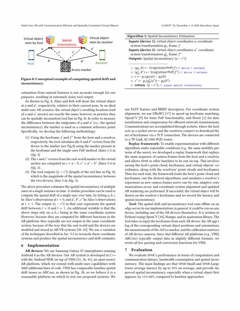
Figure 7: Feature geo distance is the average distance from
real world features to a virtual object.
Our approach is to develop a new metric to help estimate which
new keyframes and associated point clouds will produce the best
alignment and improve the spatial consistency. Simple estimation
schemes such as selecting keyframes from the host and resolver
with the lowest pixel-by-pixel differences or Hamming distance are
possible, but in our experience, this results in keyframe matches
that are distant from the virtual object, resulting in poor coordinate
system alignment and thus spatial inconsistency issues.
Instead, we leverage our understanding of the AR scenario: fea-
tures near the virtual object are more important for coordinate system
alignment. We propose a new metric based on this, łfeature geo
distancež. The feature geo distance is defined as the average dis-
tance to a virtual object over the common features in a pair of
matched keyframes, as illustrated in Fig. 7. Specifically, given a set
of features i with coordinates (xi ,yi , zi ) from keyframe fB , and the
3D coordinates of the virtual object pworldB
, we compute the feature
geo distance as:
FeatGeoDist(fB ,pworldB ) =
∑i ∈fB | |(xi ,yi , zi ) − p
worldB| |
M
whereM is the number of common features.We compute the feature
geo distance on each pair of matched frames, and only update the
pose of a virtual object if the feature geo distance is less than a
threshold (line 8 in Alg. 1). Essentially, we use feature geo distance
as a predictor of spatial inconsistency (this correlation is evaluated
in Sec. 7.3).
5.4 Spatial Inconsistency and Drift Estimation
ToolThe last module of SPAR seeks to quantify the impact of the
above modules on spatial inconsistency and drift. This is contrast
to typical AR error estimation, where human eyes can be used,
which can be inefficient [23]; Manual labeling by human eyes is
time consuming if the virtual object’s position needs to be labeled
every frame, and also be inaccurate, if there are no real-world
distance measures visible in the frame (e.g., a meterstick). In this
section, we discuss our design of a tool to automate and improve
human eyeball-based accuracy estimation.
Overall idea: Our method, in short, is to place one or more
markers (e.g., ArUco markers [44]) into the real world before run-
ning the AR app. The markers’ location and orientation can be
accurately estimated by the devices using PnP [2, 52], and used
as reference points from which to measure and compare the vir-
tual object’s position as rendered by each device. We use ArUco
markers as opposed to natural features in the scene because pose
Multi-User AR with Communication Efficient and Spatially Consistent Virtual Objects CoNEXT ’20, December 1ś4, 2020, Barcelona, Spain
Host Resolver
Virtual object
seen by host
AruCo marker
a
b
a’
b’
c c’
Spatial
inconsistency
Virtual object
seen by resolver
Figure 8: Conceptual example of computing spatial drift and
inconsistency.
estimation from natural features is not accurate enough for our
purposes, resulting in extremely noisy tool output.
As shown in Fig. 8, Alice and Bob will draw the virtual object
at a and a′, respectively, relative to their current pose. In an ideal
multi-user AR scenario, the virtual object’s resulting locations (end
of a and a′ arrows) are exactly the same; however, in practice they
can be spatially inconsistent (red line in Fig. 8). In order to measure
the difference between the endpoints of a and a′ (i.e., the spatial
inconsistency), the marker is used as a common reference point.
Specifically, we develop the following methodology:
(1) Using the keyframe f and f ′ from the host and a resolver,
respectively, the tool calculates the b and b ′ vectors from the
device to the marker (see Fig.8) using the marker present in
the keyframe and the single-user PnP method. (lines 1-2 in
Alg. 2)
(2) The c and c ′ vectors from the real-world marker to the virtual
anchor are computed as c = a − b, c ′ = a′ − b ′. (lines 3-4 in
Alg. 2).
(3) The tool outputs | |c − c ′ | | (length of the red line in Fig. 8),
which is the magnitude of the spatial inconsistency between
the two devices. (line 5 in Alg. 2).
The above procedure estimates the spatial inconsistency of multiple
users at a single instance in time. A similar procedure can be used to
compute the spatial drift of a single user over time, by letting a,b, c
be Alice’s observations at t = 0, and a′,b ′, c ′ be Alice’s observations
at t = 1. The output | |c − c ′ | | in that case represents the spatial
drift between t = 0 and t = 1. An additional wrinkle is that the
above steps rely on a,b, c being in the same coordinate system.
However, because they are computed by different functions in the
AR platform, they typically are not output in the same coordinate
system, because of the way that the real world and the devices are
modeled and stored in AR/VR systems [30, 45]. We use a variation
of the techniques described in Sec. 5.2 to reconcile these coordinate
systems and produce the spatial inconsistency and drift estimates.
6 Implementation
AR devices:We use Samsung Galaxy S7 smartphones running
Android 8 as the AR devices. Our AR system is developed in C++
with the Android NDK on top of VINS [31, 36, 41], an open-source
AR platform, which we extend with multi-user capabilities with
3000 additional lines of code. VINS has comparable baseline spatial
drift issues as ARCore, as shown in Fig. 2b, so we believe it is a
reasonable platform on which to test our proposed systems. We
Algorithm 2: Spatial Inconsistency Estimation
Inputs (device 1): virtual object coordinates a, coordinate
system transformation д0, frame f
Inputs (device 2): virtual object coordinates a′, coordinate
system transformation д′0, frame f ′
Outputs: Spatial inconsistency | |c − c ′ | |
1: (д2,b) ← SingleUserPnP(f ) // device 1 estimate
2: (д′2,b ′) ← SingleUserPnP(f ′) // device 2 estimate
3: c ← д1(д0(a)) − д2(b)
4: c ′ ← д1(д′0(a′)) − д2(b
′)
5: return | |c − c ′ | | // output spatial inconsistency
use FAST feature and BRIEF descriptors. For coordinate system
alignment, we use DBoW2 [17] to speed up keyframe matching,
OpenCV [9] for basic PnP functionality, and Boost [1] for data
serialization and compression for efficient network transmissions.
Communications are accomplished through sockets, where the host
acts as a socket server and the resolvers connect to download the
set of keyframes via a TCP connection. The devices are connected
to a TP-Link AC1900 WiFi router.
Replay framework: To enable experimentation with different
algorithms under repeatable conditions (e.g., the same mobility pat-
terns of the users), we developed a replay framework that replays
the same sequence of camera frames from the host and a resolver,
and allows SPAR or other baselines to be run on top. This involves
saving the host’s point cloud, keyframes, and virtual objects’ co-
ordinates, along with the resolvers’ point clouds and keyframes.
Then for each trial, the framework loads the host’s point cloud and
keyframes, run the desired algorithms, and emulates a resolver’s
experience as new camera frames arrive one-by-one, adaptive com-
munications occur, and coordinate system alignment and updated
AR rendering are performed. If successful, the virtual object will be
drawn on the resolver’s keyframes and we record the latency and
spatial inconsistency.
Tool: The spatial drift and inconsistency tool runs offline on an
edge server in our implementation; in general, it could be run on any
device, including one of the AR devices themselves. It is written in
Python3 using OpenCV [10], Numpy, and its quaternion library. The
tool takes as input the keyframes from each AR device, the AR app’s
log of the corresponding virtual object positions and orientations,
themeasurements of the ArUcomarker, and the calibrationmatrices
of AR device cameras. Since that different AR platforms (e.g., VINS,
ARCore) typically output data in slightly different formats, we
wrote ad hoc parsing and conversion functions for VINS.
7 EvaluationWe evaluate SPAR’s performance in terms of computation and
communication latency, bandwidth consumption and spatial incon-
sistency. The main findings are that SPAR-Small and SPAR-Large
lower average latency by up to 55% on average, and provide im-
proved spatial inconsistency, especially when a virtual object first
appears, by 11%-60%, compared to baseline approaches.

CoNEXT ’20, December 1ś4, 2020, Barcelona, Spain Ran et al.
Scenario 1 Scenario 2 Scenario 3
Room Room Room
1m
2m 2m
Host Host HostResolver Resolver
Resolver
Figure 9: User mobility pattern test cases.
7.1 SetupScenarios:We perform experiments in the lab and in a home en-
vironment. A host places a virtual object (in our case, a virtual
cube), walks around the area, and sends the relevant data once to
a resolver. This resolver then walks around the scene and tries to
render the virtual cube at the correct location. We evaluate the per-
formance from the point of view of a resolver at two time instances:
(i) initially, when the virtual object is first displayed (Sec. 7.2), and
(ii) subsequently as the resolver continues to move around and
update the virtual object’s position (Sec. 7.3). We also evaluate the
performance of the tool to estimate spatial drift and inconsistency
during these two phases (Sec. 7.4). The average WiFi speed was 8
Mbps upload and 50 Mbps download in the lab, and 8 Mbps upload
and 20 Mbps download at home.
The user mobility pattern test cases are illustrated in Fig. 9 and
described below.
• Scenario 1: Small area: The host and a resolver are mostly station-
ary, and move within a 1 m × 1 m area.
• Scenario 2: Large area + same initial position: The host and a
resolver start at the same place facing the same direction. Each
user moves independently within a 4 m × 4 m area.
• Scenario 3: Large area + different initial position: The host and
resolver start at different places. They both move independently
within a 4 m × 4 m area.
Each scenario is repeated 25 times, with each trial lasting 40-90
seconds.
Baselines: Along with the SPAR-Large and SPAR-Small strategies
proposed in Sec. 5.1, we compare against several baselines, All and
ARCore:
• All: The host sends all keyframes and associated point clouds
(already downsampled by SLAM) to a resolver.
• SPAR-Small: The host sends 5 keyframes and their associated
point clouds from before and after creating a virtual object (10
time instances total). This strategy geared towards small envi-
ronments.
• SPAR-Large: The host sends keyframes and associated point clouds
for which the virtual object is visible within the FoV and the host
is within Tkeyframe = 3 m of the virtual object. This strategy is
more conservative and geared towards large environments.
• ARCore [19]: ARCore is a highly optimized, closed-source pro-
duction level AR platform with cloud processing. We include
Figure 10: SPAR reduces total latency by up to 55% compared
to All and ARCore baselines, on average. Note that the la-
tency here is the initialization latency, when the user first
loads the AR app. Once this initialization has happened, sub-
sequent updates to the virtual objects’ locations and orien-
tations happen in real-time.
this comparison for reference; our goal is to showcase the im-
provements of our proposed methods in the open-source VINS
platform, which could then be incorporated into optimized pro-
duction platforms. Due to API restrictions, the ARCore experi-
ments differ slightly in that VINS creates a virtual object before
the host moves, while ARCore creates it after the host moves.
We also experimented with two other baselines using the individual
nearness and visibility criteria from SPAR-Large, but their results
were similar to the other baselines and omitted. We didn’t compare
performance with other AR platforms such as Hololens or ARKit
because they run on different hardware (Hololens, iPhone/iPad),
so it is difficult to have a fair comparison with SPAR, which is
prototyped on Android (although its methods are generalizable).
Metrics:We evaluate several metrics:
• Latency of Initial Virtual Object Appearance (s): This latency con-
sists of several components:
• Save: The time the host spends to adapt the AR data in prepa-
ration for transmission.
• Communication: The time spent to communicate the selected
data to a resolver. For ARCore, this includes the cloud process-
ing time.
• Load: The time a resolver spends to load the host’s data and
initialize SLAM processing.
• Resolve: The time for a resolver to move close to a virtual object
and perform coordinate system alignment.
• Spatial drift and inconsistency (cm): As discussed in Sec. 2, spatial
drift is defined as the distance that a resolver’s virtual object
changes over time(assuming a ground truth stationary virtual
object). Spatial inconsistency is defined as the distance between
a host and resolver’s virtual object instances at a given time.
• Failure rate: A virtual object can fail to appear on a resolver’s
screen if the coordinate system alignment cannot find similar
Multi-User AR with Communication Efficient and Spatially Consistent Virtual Objects CoNEXT ’20, December 1ś4, 2020, Barcelona, Spain
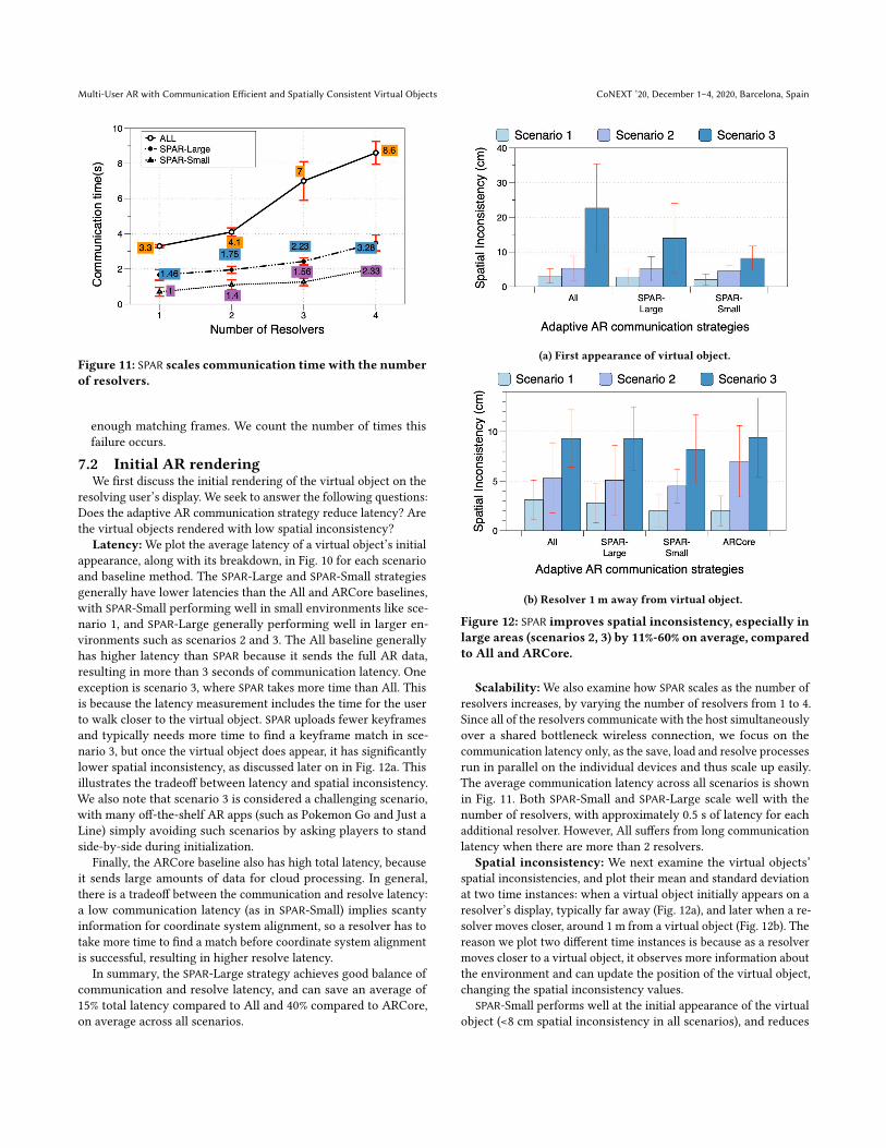
Figure 11: SPAR scales communication time with the number
of resolvers.
enough matching frames. We count the number of times this
failure occurs.
7.2 Initial AR renderingWe first discuss the initial rendering of the virtual object on the
resolving user’s display. We seek to answer the following questions:
Does the adaptive AR communication strategy reduce latency? Are
the virtual objects rendered with low spatial inconsistency?
Latency:We plot the average latency of a virtual object’s initial
appearance, along with its breakdown, in Fig. 10 for each scenario
and baseline method. The SPAR-Large and SPAR-Small strategies
generally have lower latencies than the All and ARCore baselines,
with SPAR-Small performing well in small environments like sce-
nario 1, and SPAR-Large generally performing well in larger en-
vironments such as scenarios 2 and 3. The All baseline generally
has higher latency than SPAR because it sends the full AR data,
resulting in more than 3 seconds of communication latency. One
exception is scenario 3, where SPAR takes more time than All. This
is because the latency measurement includes the time for the user
to walk closer to the virtual object. SPAR uploads fewer keyframes
and typically needs more time to find a keyframe match in sce-
nario 3, but once the virtual object does appear, it has significantly
lower spatial inconsistency, as discussed later on in Fig. 12a. This
illustrates the tradeoff between latency and spatial inconsistency.
We also note that scenario 3 is considered a challenging scenario,
with many off-the-shelf AR apps (such as Pokemon Go and Just a
Line) simply avoiding such scenarios by asking players to stand
side-by-side during initialization.
Finally, the ARCore baseline also has high total latency, because
it sends large amounts of data for cloud processing. In general,
there is a tradeoff between the communication and resolve latency:
a low communication latency (as in SPAR-Small) implies scanty
information for coordinate system alignment, so a resolver has to
take more time to find a match before coordinate system alignment
is successful, resulting in higher resolve latency.
In summary, the SPAR-Large strategy achieves good balance of
communication and resolve latency, and can save an average of
15% total latency compared to All and 40% compared to ARCore,
on average across all scenarios.
(a) First appearance of virtual object.
(b) Resolver 1 m away from virtual object.
Figure 12: SPAR improves spatial inconsistency, especially in
large areas (scenarios 2, 3) by 11%-60% on average, compared
to All and ARCore.
Scalability:We also examine how SPAR scales as the number of
resolvers increases, by varying the number of resolvers from 1 to 4.
Since all of the resolvers communicate with the host simultaneously
over a shared bottleneck wireless connection, we focus on the
communication latency only, as the save, load and resolve processes
run in parallel on the individual devices and thus scale up easily.
The average communication latency across all scenarios is shown
in Fig. 11. Both SPAR-Small and SPAR-Large scale well with the
number of resolvers, with approximately 0.5 s of latency for each
additional resolver. However, All suffers from long communication
latency when there are more than 2 resolvers.
Spatial inconsistency: We next examine the virtual objects’
spatial inconsistencies, and plot their mean and standard deviation
at two time instances: when a virtual object initially appears on a
resolver’s display, typically far away (Fig. 12a), and later when a re-
solver moves closer, around 1 m from a virtual object (Fig. 12b). The
reason we plot two different time instances is because as a resolver
moves closer to a virtual object, it observes more information about
the environment and can update the position of the virtual object,
changing the spatial inconsistency values.
SPAR-Small performs well at the initial appearance of the virtual
object (<8 cm spatial inconsistency in all scenarios), and reduces
CoNEXT ’20, December 1ś4, 2020, Barcelona, Spain Ran et al.
the spatial inconsistency as the resolver gets closer to the virtual
object. One drawback of SPAR-Small is that it has high latency
in the large environments it was not designed for (see Fig. 10).
In large environments (scenarios 2 and 3), SPAR-Large has lower
spatial inconsistency than the All baseline when the virtual object
first appears (Fig. 12a), and compared to the ARCore baseline when
close to a virtual object (Fig. 12b). Hence SPAR-Small and SPAR-Large
work well for the respective environments they were designed for.
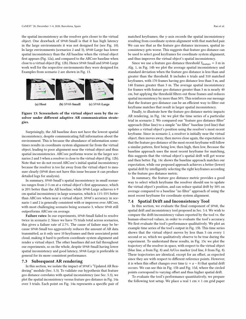
Examples from scenario 2 are shown in Fig. 13.
(a) Host (b) SPAR-Small (c) SPAR-Large
Figure 13: Screenshots of the virtual object seen by the re-
solver under different adaptive AR communication strate-
gies.
Surprisingly, the All baseline does not have the lowest spatial
inconsistency, despite communicating full information about the
environment. This is because the abundance of information some-
times results in coordinate system alignment far from the virtual
object, leading to poor alignment near the virtual object and thus
spatial inconsistencies. ARCore performs worse in the larger sce-
narios 2 and 3 when a resolver is close to the virtual object (Fig. 12b).
Note that we do not record ARCore’s initial spatial inconsistency
because the resolver is too far away from the virtual object to mea-
sure clearly (SPAR does not have this issue because it can produce
detailed logs for analysis).
In summary, SPAR-Small’s spatial inconsistency in small scenar-
ios ranges from 2-3 cm at a virtual object’s first appearance, which
is 20% better than the All baseline; while SPAR-Large achieves 6-9
cm spatial inconsistency in large scenarios, which is 11%-35% better
than ARCore when near a virtual object. SPAR’s accuracy in sce-
nario 1 and 2 is generally consistent with or improves over ARCore,
with most challenging scenario being scenario 3, where SPAR still
outperforms ARCore on average.
Failure rates: In our experiments, SPAR-Small failed to resolve
twice in scenario 2. Since we have 75 trials total across scenarios,
this gives a failure rate of 2.7%. The cause of failure may be be-
cause SPAR-Small too aggressively reduces the amount of AR data
transmitted, as it only save 10 keyframes and their associated point
cloud, making it hard to perform coordinate system alignment and
render a virtual object. The other baselines did not fail throughout
our experiments, so on the whole, despite SPAR-Small having lower
spatial inconsistency and good latency, SPAR-Large is preferable in
general for its more consistent performance.
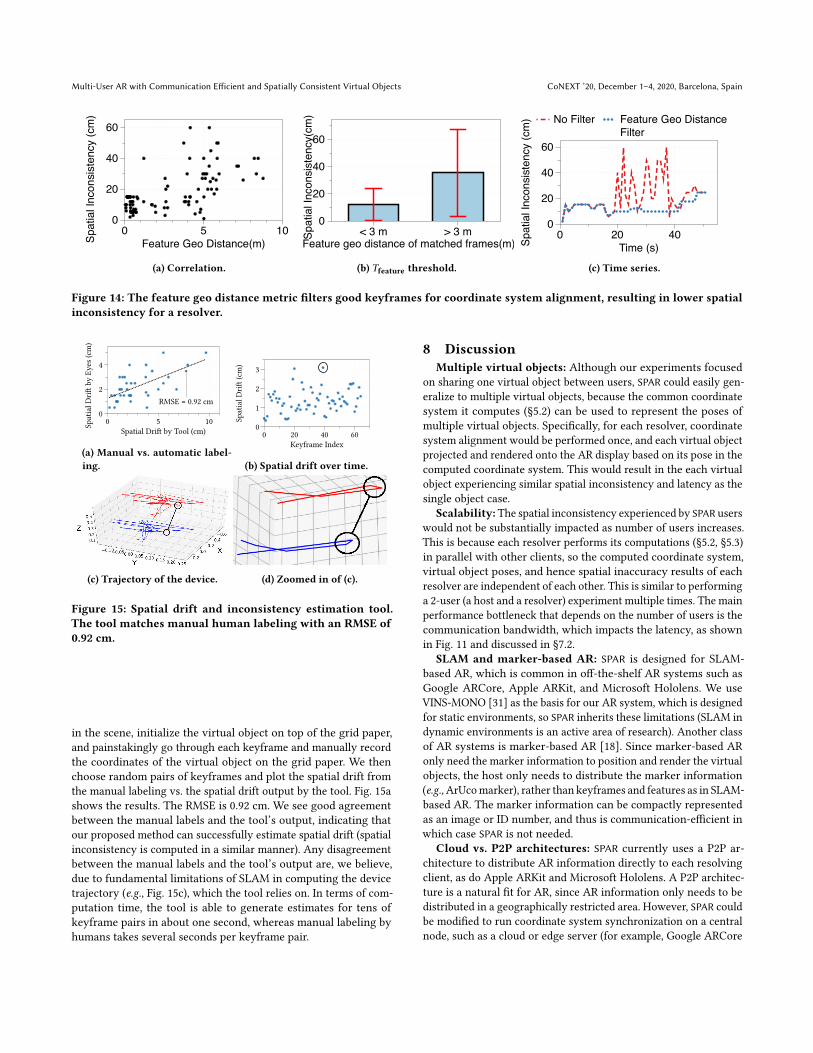
7.3 Subsequent AR renderingIn this section, we isolate the impact of SPAR’s łUpdated AR Ren-
deringž module (Sec. 5.3). To validate our hypothesis that feature
geo distance correlates with spatial inconsistency (see Sec. 5.3), we
plot the spatial inconsistency versus feature geo distance in Fig. 14a
over 3 trials. Each point on Fig. 14a represents a specific pair of
matched keyframes; the y-axis records the spatial inconsistency
resulting from coordinate system alignment with that matched pair.
We can see that as the feature geo distance increases, spatial in-
consistency gets worse. This suggests that feature geo distance can
be used to select good keyframes for coordinate system alignment,
and thus improves the virtual object’s spatial inconsistency.
Since we use a feature geo distance threshold Tfeature = 3 m in
Alg. 1, in Fig. 14b we plot the average spatial inconsistency and
standard deviation when the feature geo distance is less than and
greater than the threshold. It includes 6 trials and 310 matched
keyframes, with 170 frames having geo distance less than 3 m, and
140 frames greater than 3 m. The average spatial inconsistency
for frames with feature geo distance greater than 3 m is nearly 40
cm, but applying the threshold filters out those frames and reduces
spatial inconsistency bymore than 50%. This reinforces ourmessage
that the feature geo distance can be an efficient way to filter out
keyframe matches that result in larger spatial inconsistency.
Finally, to illustrate how the feature geo distance metric impacts
AR rendering, in Fig. 14c we plot the time series of a particular
trial in scenario 2. We compared our łfeature geo distance filterž
approach (blue line) to a simple łno filterž baseline (red line) that
updates a virtual object’s position using the resolver’s most recent
keyframe. Since in scenario 2, a resolver is initially near the virtual
object, then moves away, then moves close again, the expectation is
that the feature geo distance of the most recent keyframe will follow
a similar pattern, first being low, then high, then low, Because the
baseline approach uses the most recent keyframe for matching,
this suggests that the virtual object’s spatial drift will get worse
and then better. Fig. 14c shows the baseline approach matches our
expectation, while our proposed approach achieves a better (lower)
spatial drift by intelligently selecting the right keyframes according
to the feature geo distance metric.
In summary, the feature geo distance metric provides a good
way to select which keyframe the resolver should use to update
the virtual object’s position, and can reduce spatial drift by 50% on
average compared to a baseline łno filterž approach of using the
most recent keyframe for coordinate system alignment.
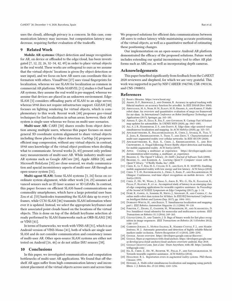
7.4 Spatial Drift and Inconsistency ToolIn this section, we evaluate the final component of SPAR, the
spatial drift and inconsistency tool proposed in Sec. 5.4. We wish to
compare the drift/inconsistency values reported by the tool vs. the
human-observed values, in order to evaluate the tool’s accuracy.
We first evaluate the tool’s performance qualitatively. We plot an
example time series of the tool’s output in Fig. 15b. This time series
shows that the virtual object moves by less than 3 cm every 1
second or so, which we qualitatively observe to be true during the
experiment. To understand these results, in Fig. 15c we plot the
trajectory of the resolver in space, with respect to the virtual object
(blue line, a from Fig. 8) and ArUco marker (red line, b from Fig. 8).
These trajectories are identical, except for an offset, as expected
since they are with respect to different reference points. However,
it is when this offset changes over time (c = a − b) that spatial drift
occurs. We can see this in Fig. 15b and Fig. 15d, where the circled
points correspond to varying offset and thus higher spatial drift.
To evaluate the tool’s performance quantitatively, we prepare
the following test setup. We place a real 1 cm × 1 cm grid paper
Multi-User AR with Communication Efficient and Spatially Consistent Virtual Objects CoNEXT ’20, December 1ś4, 2020, Barcelona, SpainS
pa
tia
l In
co
nsis
ten
cy (
cm
)
0
20
40
60
Feature Geo Distance(m)
0 5 10
(a) Correlation.
Sp
atia
l In
co
nsis
ten
cy(c
m)
Feature geo distance of matched frames(m)
0
20
40
60
< 3 m > 3 m
(b) Tfeature threshold.
No Filter Feature Geo Distance
Filter
Sp
atia
l In
co
nsis
ten
cy (
cm
)
0
20
40
60
Time (s)
0 20 40
(c) Time series.
Figure 14: The feature geo distance metric filters good keyframes for coordinate system alignment, resulting in lower spatial
inconsistency for a resolver.
Sp
atia
l D
rift
by
Ey
es (
cm)
RMSE = 0.92 cm
0
2
4
Spatial Drift by Tool (cm)
0 5 10
(a) Manual vs. automatic label-
ing.
Sp
atia
l D
rift
(cm
)
0
1
2
3
Keyframe Index
0 20 40 60
(b) Spatial drift over time.
(c) Trajectory of the device. (d) Zoomed in of (c).
Figure 15: Spatial drift and inconsistency estimation tool.
The tool matches manual human labeling with an RMSE of
0.92 cm.
in the scene, initialize the virtual object on top of the grid paper,
and painstakingly go through each keyframe and manually record
the coordinates of the virtual object on the grid paper. We then
choose random pairs of keyframes and plot the spatial drift from
the manual labeling vs. the spatial drift output by the tool. Fig. 15a
shows the results. The RMSE is 0.92 cm. We see good agreement
between the manual labels and the tool’s output, indicating that
our proposed method can successfully estimate spatial drift (spatial
inconsistency is computed in a similar manner). Any disagreement
between the manual labels and the tool’s output are, we believe,
due to fundamental limitations of SLAM in computing the device
trajectory (e.g., Fig. 15c), which the tool relies on. In terms of com-
putation time, the tool is able to generate estimates for tens of
keyframe pairs in about one second, whereas manual labeling by
humans takes several seconds per keyframe pair.
8 Discussion
Multiple virtual objects: Although our experiments focused
on sharing one virtual object between users, SPAR could easily gen-
eralize to multiple virtual objects, because the common coordinate
system it computes (ğ5.2) can be used to represent the poses of
multiple virtual objects. Specifically, for each resolver, coordinate
system alignment would be performed once, and each virtual object
projected and rendered onto the AR display based on its pose in the
computed coordinate system. This would result in the each virtual
object experiencing similar spatial inconsistency and latency as the
single object case.
Scalability:The spatial inconsistency experienced by SPAR users
would not be substantially impacted as number of users increases.
This is because each resolver performs its computations (ğ5.2, ğ5.3)
in parallel with other clients, so the computed coordinate system,
virtual object poses, and hence spatial inaccuracy results of each
resolver are independent of each other. This is similar to performing
a 2-user (a host and a resolver) experiment multiple times. The main
performance bottleneck that depends on the number of users is the
communication bandwidth, which impacts the latency, as shown
in Fig. 11 and discussed in ğ7.2.
SLAM and marker-based AR: SPAR is designed for SLAM-
based AR, which is common in off-the-shelf AR systems such as
Google ARCore, Apple ARKit, and Microsoft Hololens. We use
VINS-MONO [31] as the basis for our AR system, which is designed
for static environments, so SPAR inherits these limitations (SLAM in
dynamic environments is an active area of research). Another class
of AR systems is marker-based AR [18]. Since marker-based AR
only need the marker information to position and render the virtual
objects, the host only needs to distribute the marker information
(e.g.,ArUcomarker), rather than keyframes and features as in SLAM-
based AR. The marker information can be compactly represented
as an image or ID number, and thus is communication-efficient in
which case SPAR is not needed.
Cloud vs. P2P architectures: SPAR currently uses a P2P ar-
chitecture to distribute AR information directly to each resolving
client, as do Apple ARKit and Microsoft Hololens. A P2P architec-
ture is a natural fit for AR, since AR information only needs to be
distributed in a geographically restricted area. However, SPAR could
be modified to run coordinate system synchronization on a central
node, such as a cloud or edge server (for example, Google ARCore
CoNEXT ’20, December 1ś4, 2020, Barcelona, Spain Ran et al.
uses the cloud), although privacy is a concern. In this case, com-
munication latency may increase, but computation latency may
decrease, requiring further evaluation of the tradeoffs.
9 Related Work
Mobile AR systems: Object detection and image recognition
for AR, on device or offloaded to the edge/cloud, has been investi-
gated [7, 12, 22, 26, 32ś34, 42, 49] in order to place virtual objects
in the real world. These works are orthogonal to ours as we assume
that the virtual objects’ locations is given (by object detection or
user input), and we focus on how AR users can coordinate this in-
formation with others. VisualPrint [27] uses visual fingerprints for
localization, whereas we use SLAM for localization as common in
commercial AR platforms.While MARVEL [11] studies 6-DoF based
AR systems, they assume the real world is pre-mapped, whereas we
assume that devices are placed in an unknown environment. Edge-
SLAM [5] considers offloading parts of SLAM to an edge server,
whereas SPAR does not require infrastructure support. GLEAM [40]
focuses on lighting rendering for virtual objects, which is com-
plementary to this work. Recent work [48] proposes geo-visual
techniques for fast localization in urban areas; however, their AR
system is single-user whereas we focus on multi-user scenarios.
Multi-user AR: CARS [50] shares results from object detec-
tion among multiple users, whereas this paper focuses on more
general 3D coordinate system alignment to share virtual objects
including those placed by object detection. CarMap [4] proposes
efficient map compression, without any virtual objects; in contrast,
SPAR uses knowledge of the virtual object positions when deciding
what to communicate. Several works [6, 43] present only prelimi-
nary measurements of multi-user AR. While industry multi-user
AR systems such as Google ARCore [20], Apple ARKit [8], and
Microsoft HoloLens [35] are close-sourced, we study communica-
tion and spacial inconsistency aspects of multi-user AR through an
open-source system [31].
Multi-agent SLAM: Some SLAM systems [3, 24] focus on co-
ordinate system alignment, while other work [14, 25] assumes ad-
vanced sensors such as 2D laser scanner or 3D LiDARs. In contrast,
this paper focuses on efficient SLAM-based communications on
commodity smartphones, which have a large potential user base.
Zou et al. [53] hardcodes transmitting the SLAM data up to every 5
frames, while CCM-SLAM [46] transmits SLAM information when-
ever it is updated. Instead, we select the appropriate keyframes and
their associated point clouds based on the locations of the virtual
objects. This is done on top of the default keyframe selection al-
ready performed by SLAM frameworks such as ORB-SLAM2 [38]
or VINS [41].
In terms of frameworks, we work with VINS-AR [31], which is an
Android version of VINS-Mono [41], both of which are single-user
SLAM and do not consider communication and consistency issues
of multi-user AR. Other open-source SLAM systems are either not
tested on Android [16, 46] or do not utilize IMU sensors [38].
10 ConclusionsIn this paper, we investigated communication and computation
bottlenecks of multi-user AR applications. We found that off-the-
shelf AR apps suffer from high communication latency and incon-
sistent placement of the virtual objects across users and across time.
We proposed solutions for efficient data communications between
AR users to reduce latency while maintaining accurate positioning
of the virtual objects, as well as a quantitative method of estimating
these positioning changes.
Our implementation on an open-source Android AR platform
demonstrated the efficacy of the proposed solutions. Future work
includes extending our spatial inconsistency tool to other AR plat-
forms such as ARCore, as well as incorporating depth cameras.
AcknowledgementsThis paper benefited significantly from feedback from the CoNEXT
2020 reviewers and shepherd, for which we are very grateful. This
work was supported in part by NSF CAREER 1942700, CSR-1903136,
and CNS-1908051.
References[1] Boost c libraries. https://www.boost.org/.[2] Abawi, D. F., Bienwald, J., and Dorner, R. Accuracy in optical tracking with
fiducial markers: an accuracy function for artoolkit. In IEEE ISMAR (Nov 2004).[3] Abdulgalil, M. A., Nasr, M.M., Elalfy, M. H., Khamis, A., and Karray, F.Multi-
robot slam: An overview and quantitative evaluation of mrgs ros frameworkfor mr-slam. In International Conference on Robot Intelligence Technology andApplications (2017), Springer, pp. 165ś183.
[4] Ahmad, F., Qiu, H., Eells, R., Bai, F., and Govindan, R. Carmap: Fast 3d featuremap updates for automobiles. In USENIX NSDI (2020), pp. 1063ś1081.
[5] Ali, A. J. B., Hashemifar, Z. S., and Dantu, K. Edge-slam: edge-assisted visualsimultaneous localization and mapping. In ACM MobiSys (2020), pp. 325ś337.
[6] Apicharttrisorn, K., Balasubramanian, B., Chen, J., Sivaraj, R., Tsai, Y.-Z., Jana, R., Krishnamurthy, S., Tran, T., and Zhou, Y. Characterization ofmulti-user augmented reality over cellular networks. In IEEE SECON (2020).
[7] Apicharttrisorn, K., Ran, X., Chen, J., Krishnamurthy, S., and Roy-Chowdhury, A. Frugal following: Power thrifty object detection and trackingfor mobile augmented reality. ACM SenSys (2019).
[8] Apple. Creating a multiuser ar experience. https://developer.apple.com/documentation/arkit/creating_a_multiuser_ar_experience.
[9] Bradski, G. The OpenCV Library. Dr. Dobb’s Journal of Software Tools (2000).[10] Bradski, G., and Kaehler, A. Learning OpenCV: Computer vision with the
OpenCV library. " O’Reilly Media, Inc.", 2008.[11] Chen, K., Li, T., Kim, H.-S., Culler, D. E., and Katz, R. H. MARVEL: Enabling
mobile augmented reality with low energy and low latency. ACM Sensys (2018).[12] Chen, T. Y.-H., Ravindranath, L., Deng, S., Bahl, P., and Balakrishnan, H.
Glimpse: Continuous, real-time object recognition on mobile devices. ACMSenSys (2015).
[13] Chen, Z., Hu, W., Wang, J., Zhao, S., Amos, B., Wu, G., Ha, K., Elgazzar, K.,Pillai, P., Klatzky, R., et al. An empirical study of latency in an emerging classof edge computing applications for wearable cognitive assistance. In Proceedingsof the Second ACM/IEEE Symposium on Edge Computing (2017), pp. 1ś14.
[14] Dubé, R., Gawel, A., Sommer, H., Nieto, J., Siegwart, R., and Cadena, C. Anonline multi-robot slam system for 3d lidars. In IEEE/RSJ International Conferenceon Intelligent Robots and Systems (Sep. 2017), pp. 1004ś1011.
[15] Durrant-Whyte, H., and Bailey, T. Simultaneous localization and mapping:part i. IEEE Robotics Automation Magazine 13, 2 (2006), 99ś110.
[16] Forster, C., Zhang, Z., Gassner, M., Werlberger, M., and Scaramuzza, D.Svo: Semidirect visual odometry for monocular and multicamera systems. IEEETransactions on Robotics 33, 2 (2016), 249ś265.
[17] Gálvez-López, D., and Tardós, J. D. Bags of binary words for fast place recog-nition in image sequences. IEEE Transactions on Robotics 28, 5 (October 2012),1188ś1197.
[18] Garrido-Jurado, S., Muñoz-Salinas, R., Madrid-Cuevas, F. J., and Marín-Jiménez, M. J. Automatic generation and detection of highly reliable fiducialmarkers under occlusion. Pattern Recognition 47, 6 (2014), 2280ś2292.
[19] Google. Arcore overview. https://developers.google.com/ar/discover/.[20] Google. Share ar experiences with cloud anchors. https://developers.google.com/
ar/develop/java/cloud-anchors/cloud-anchors-overview-android, May 2018.[21] Google Creative Labs. Just a Line - Draw Anywhere, with AR. https://justaline.
withgoogle.com/.[22] Ha, K., Chen, Z., Hu, W., Richter, W., Pillai, P., and Satyanarayanan, M.
Towards wearable cognitive assistance. ACM MobiSys (2014).[23] Holloway, R. L. Registration errors in augmented reality systems. PhD thesis,
Citeseer, 1995.[24] Howard, A. Multi-robot simultaneous localization and mapping using particle
filters. I. J. Robotic Res. 25 (12 2006), 1243ś1256.
Multi-User AR with Communication Efficient and Spatially Consistent Virtual Objects CoNEXT ’20, December 1ś4, 2020, Barcelona, Spain
[25] Jafri, S., and Chellali, R. A distributedmulti robot slam system for environmentlearning. In IEEE Workshop on Robotic Intelligence in Informationally StructuredSpace (2013).
[26] Jain, P., Manweiler, J., and Roy Choudhury, R. Overlay: Practical mobileaugmented reality. ACM MobiSys (2015).
[27] Jain, P., Manweiler, J., and Roy Choudhury, R. Low bandwidth offload formobile AR. ACM CoNEXT (2016).
[28] Jinyu, L., Bangbang, Y., Danpeng, C., Nan, W., Guofeng, Z., and Hujun, B. Sur-vey and evaluation of monocular visual-inertial slam algorithms for augmentedreality. Virtual Reality & Intelligent Hardware 1, 4 (2019), 386ś410.
[29] Kyoung Shin Park, and Kenyon, R. V. Effects of network characteristics onhuman performance in a collaborative virtual environment. In IEEE VirtualReality (Mar. 1999).
[30] LaValle, S. Virtual Reality. Cambridge University Press.[31] Li, P., Qin, T., Hu, B., Zhu, F., and Shen, S. Monocular visual-inertial state
estimation for mobile augmented reality. In IEEE ISMAR (2017), pp. 11ś21.[32] Liu, L., Li, H., and Gruteser, M. Edge assisted real-time object detection for
mobile augmented reality. ACM MobiCom (2019).[33] Liu, Q., and Han, T. Dare: Dynamic adaptive mobile augmented reality with
edge computing. IEEE ICNP (2018).[34] Liu, Z., Lan, G., Stojkovic, J., Zhang, Y., Joe-Wong, C., and Gorlatova, M.
Collabar: Edge-assisted collaborative image recognition for mobile augmentedreality. In ACM/IEEE IPSN (2020).
[35] Microsoft. Shared experiences in unity. https://docs.microsoft.com/en-us/windows/mixed-reality/shared-experiences-in-unity, March 2018.
[36] Moeller, J. jannismoeller/vins-mobile-android. https://github.com/jannismoeller/VINS-Mobile-Android, Jul 2019.
[37] Mojang. Minecraft for Android. https://www.minecraft.net/en-us/store/minecraft-android/.
[38] Mur-Artal, R., and Tardós, J. D. Orb-slam2: An open-source slam system formonocular, stereo, and rgb-d cameras. IEEE Transactions on Robotics 33, 5 (2017),1255ś1262.
[39] Niantic. Pokemon Go. https://www.pokemongo.com/en-us/.[40] Prakash, S., Bahremand, A., Nguyen, L. D., and LiKamWa, R. GLEAM: An
Illumination Estimation Framework for Real-time Photorealistic Augmented
Reality on Mobile Devices. ACM MobiSys (2019).[41] Qin, T., Li, P., and Shen, S. Vins-mono: A robust and versatile monocular
visual-inertial state estimator. IEEE Transactions on Robotics 34, 4 (Aug 2018),1004ś1020.
[42] Ran, X., Chen, H., Liu, Z., and Chen, J. Deepdecision: A mobile deep learningframework for edge video analytics. IEEE INFOCOM (2018).
[43] Ran, X., Slocum, C., Gorlatova, M., and Chen, J. Sharear: Communication-efficient multi-user mobile augmented reality. In ACM HotNets Workshop (2019),pp. 109ś116.
[44] Romero-Ramirez, F., Muñoz-Salinas, R., and Medina-Carnicer, R. Speededup detection of squared fiducial markers. Image and Vision Computing 76 (062018).
[45] Schmalstieg, D., and Hollerer, T. Augmented reality: principles and practice.Addison-Wesley Professional, 2016.
[46] Schmuck, P., and Chli, M. Multi-uav collaborative monocular slam. IEEEInternational Conference on Robotics and Automation (2017).
[47] Sturm, J., Engelhard, N., Endres, F., Burgard, W., and Cremers, D. A bench-mark for the evaluation of rgb-d slam systems. In IEEE/RSJ International Confer-ence on Intelligent Robots and Systems (2012).
[48] Xu, T., Wang, G., and Lin, F. X. Practical urban localization for mobile ar. InACM HotMobile Workshop (2020).
[49] Zhang, W., Han, B., and Hui, P. Jaguar: Low Latency Mobile Augmented Realitywith Flexible Tracking. ACM Multimedia (2018).
[50] Zhang, W., Han, B., Hui, P., Gopalakrishnan, V., Zavesky, E., and Qian, F.Cars: Collaborative augmented reality for socialization. ACM HotMobile (2018).
[51] Zheng, F. Spatio-temporal registration in augmented reality. PhD thesis, TheUniversity of North Carolina at Chapel Hill, 2015.
[52] Zheng, Y., Kuang, Y., Sugimoto, S., Åström, K., and Okutomi, M. Revisitingthe pnp problem: A fast, general and optimal solution. In IEEE ICCV (2013),pp. 2344ś2351.
[53] Zou, D., and Tan, P. Coslam: Collaborative visual slam in dynamic environments.IEEE Transactions on Pattern Analysis and Machine Intelligence 35, 2 (2012), 354ś366.