Interactive and Multimodal-based Augmented Reality for ...iphome.hhi.de/wisotzky/Wisotzky et...
8
Interactive and Multimodal-based Augmented Reality for Remote Assistance using a Digital Surgical Microscope Eric L. Wisotzky * Fraunhofer HHI & HU Berlin Jean-Claude Rosenthal † Fraunhofer HHI Peter Eisert Fraunhofer HHI & HU Berlin Anna Hilsmann Fraunhofer HHI Falko Schmid Ubimax GmbH Michael Bauer pripares GmbH Armin Schneider ARRI Medical GmbH Florian C. Uecker Charité Universitätsmedizin Berlin ABSTRACT We present an interactive and multimodal-based augmented real- ity system for computer-assisted surgery in the context of ear, nose and throat (ENT) treatment. The proposed processing pipeline uses fully digital stereoscopic imaging devices, which support multi- spectral and white light imaging to generate high resolution image data, and consists of five modules. Input/output data handling, a hy- brid multimodal image analysis and a bi-directional interactive aug- mented reality (AR) and mixed reality (MR) interface for local and remote surgical assistance are of high relevance for the complete framework. The hybrid multimodal 3D scene analysis module uses different wavelengths to classify tissue structures and combines this spectral data with metric 3D information. Additionally, we propose a zoom-independent intraoperative tool for virtual ossicular pros- thesis insertion (e.g. stapedectomy) guaranteeing very high metric accuracy in sub-millimeter range (1/10 mm). A bi-directional in- teractive AR/MR communication module guarantees low latency, while consisting surgical information and avoiding informational overload. Display agnostic AR/MR visualization can show our an- alyzed data synchronized inside the digital binocular, the 3D dis- play or any connected head-mounted-display (HMD). In addition, the analyzed data can be enriched with annotations by involving external clinical experts using AR/MR and furthermore an accurate registration of preoperative data. The benefits of such a collabora- tive surgical system are manifold and will lead to a highly improved patient outcome through an easier tissue classification and reduced surgery risk. Index Terms: H.5.1 [Information Interfaces And Presentation]: Multimedia Information Systems—Artificial, augmented, and vir- * e-mail:[email protected] † e-mail:[email protected] Both authors contributed equally to this work as first author tual realities; I.2.1 [Artificial Intelligence]: Applications and Expert Systems—Medicine and science; I.2.10 [Artificial Intelligence]: Vision and Scene Understanding—3D/stereo scene analysis; I.4.8 [Image Processing And Computer Vision]: Scene Analysis— Stereo; J.3 [Computer Applications]: Life And Medical Sciences— Medical information systems; 1 I NTRODUCTION During surgery, a surgeon differentiates between healthy tissue structures, which have to be maintained, and abnormal or damaged tissue, which has to be removed, replaced or reconnected. This con- tinuous differentiation is based on his experience and knowledge only and entails great risk because injuring important structures, as nerves, can cause permanent damage to the patient’s health. Nowa- days, optical devices, like magnifying glasses, surgical microscopes and endoscopes, are used to support the surgeon in more than every second surgery [17]. In some medical fields the number increases up to 80% usage [24], as a three dimensional optical magnification of the operating field allows more complicated and complex surg- eries. The general working principle of surgical microscopes has been consistent during the last decades, distinguishing between the Greenough principle using two separate objectives and the Com- mon Main Objective (CMO) / telescope principle using one shared main objective (Fig. 1). Such microscopic systems have always been using analogous optical imaging systems and are well under- stood. Nonetheless, a simple analog and purely optical magnification does not give information about the accurate scale of the tissue structures and tissue characteristics, as such systems show sev- eral drawbacks as soon as modern computer vision algorithms or medical augmented reality (AR)/ mixed reality (MR) applications shall be applied. First, a beam splitter is obligatory to digitize the analog input signal, resulting in lower image quality in terms of contrast and resolution. Additionally, the captured perspective differs from the surgeon’s field-of-view. Further, system calibra- tion and preoperative data registration is complicated and suffers from low spatial accuracy. Besides these limiting imaging fac-
Transcript of Interactive and Multimodal-based Augmented Reality for ...iphome.hhi.de/wisotzky/Wisotzky et...
Interactive and Multimodal-based Augmented Reality for Remote
Assistance using a Digital Surgical Microscope
Eric L. Wisotzky ∗
Fraunhofer HHI & HU Berlin
Jean-Claude Rosenthal†
Fraunhofer HHI
Peter Eisert
Fraunhofer HHI & HU Berlin
Anna Hilsmann
Fraunhofer HHI
Falko Schmid
Ubimax GmbH
Michael Bauer
pripares GmbH
Armin Schneider
ARRI Medical GmbH
Florian C. Uecker
Charité Universitätsmedizin Berlin
ABSTRACT
We present an interactive and multimodal-based augmented real-ity system for computer-assisted surgery in the context of ear, noseand throat (ENT) treatment. The proposed processing pipeline usesfully digital stereoscopic imaging devices, which support multi-spectral and white light imaging to generate high resolution imagedata, and consists of five modules. Input/output data handling, a hy-brid multimodal image analysis and a bi-directional interactive aug-mented reality (AR) and mixed reality (MR) interface for local andremote surgical assistance are of high relevance for the completeframework. The hybrid multimodal 3D scene analysis module usesdifferent wavelengths to classify tissue structures and combines thisspectral data with metric 3D information. Additionally, we proposea zoom-independent intraoperative tool for virtual ossicular pros-thesis insertion (e.g. stapedectomy) guaranteeing very high metricaccuracy in sub-millimeter range (1/10 mm). A bi-directional in-teractive AR/MR communication module guarantees low latency,while consisting surgical information and avoiding informationaloverload. Display agnostic AR/MR visualization can show our an-alyzed data synchronized inside the digital binocular, the 3D dis-play or any connected head-mounted-display (HMD). In addition,the analyzed data can be enriched with annotations by involvingexternal clinical experts using AR/MR and furthermore an accurateregistration of preoperative data. The benefits of such a collabora-tive surgical system are manifold and will lead to a highly improvedpatient outcome through an easier tissue classification and reducedsurgery risk.
Index Terms: H.5.1 [Information Interfaces And Presentation]:Multimedia Information Systems—Artificial, augmented, and vir-
∗e-mail:[email protected]†e-mail:[email protected]
Both authors contributed equally to this work as first author
tual realities; I.2.1 [Artificial Intelligence]: Applications and ExpertSystems—Medicine and science; I.2.10 [Artificial Intelligence]:Vision and Scene Understanding—3D/stereo scene analysis; I.4.8[Image Processing And Computer Vision]: Scene Analysis—Stereo; J.3 [Computer Applications]: Life And Medical Sciences—Medical information systems;
1 INTRODUCTION
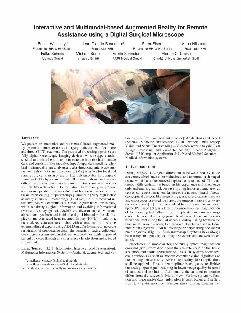
During surgery, a surgeon differentiates between healthy tissuestructures, which have to be maintained, and abnormal or damagedtissue, which has to be removed, replaced or reconnected. This con-tinuous differentiation is based on his experience and knowledgeonly and entails great risk because injuring important structures, asnerves, can cause permanent damage to the patient’s health. Nowa-days, optical devices, like magnifying glasses, surgical microscopesand endoscopes, are used to support the surgeon in more than everysecond surgery [17]. In some medical fields the number increasesup to 80% usage [24], as a three dimensional optical magnificationof the operating field allows more complicated and complex surg-eries. The general working principle of surgical microscopes hasbeen consistent during the last decades, distinguishing between theGreenough principle using two separate objectives and the Com-mon Main Objective (CMO) / telescope principle using one sharedmain objective (Fig. 1). Such microscopic systems have alwaysbeen using analogous optical imaging systems and are well under-stood.
Nonetheless, a simple analog and purely optical magnificationdoes not give information about the accurate scale of the tissuestructures and tissue characteristics, as such systems show sev-eral drawbacks as soon as modern computer vision algorithms ormedical augmented reality (AR)/ mixed reality (MR) applicationsshall be applied. First, a beam splitter is obligatory to digitizethe analog input signal, resulting in lower image quality in termsof contrast and resolution. Additionally, the captured perspectivediffers from the surgeon’s field-of-view. Further, system calibra-tion and preoperative data registration is complicated and suffersfrom low spatial accuracy. Besides these limiting imaging fac-
(a) (b)
Figure 1: Microscope optical path - simplified visualization: (a)CMO principle (b) Greenough principle
tors, current medical AR systems rely on external tracking hard-ware, e.g. electro-magnetic tracking (EMT) or optical tracking sys-tems based on infrared light using fiducial markers. These systemshold further challenges, as EMT can suffer from signal interferenceand optical tracking systems need a line-of-sight to work properly[40, 19, 7]. The configuration of such a system is time-consuming,complicated, error-prone and can easily interrupt the ongoing sur-gical procedure.
As the possibilities resulting from digitization are of increas-ing importance, digital microscopes and endoscopes are increas-ingly being used. Such fully digital devices consist of a completedigital processing chain enabling new forms of integrated imageprocessing algorithms, intraoperative assistance and surgical awareAR/MR information visualization. The display technology is cho-sen depending on the intended surgical use. In the presented ap-plication, we use the digital binocular as the primary display forvisualization, nonetheless augmented data can be distributed to anyexternal 2D/3D display or remote VR/AR visualization unit e.g.AR glasses, HMD. Thus, consulting external experts using AR/MRcommunication during surgery becomes more feasible. A detailedoverview for endoscopic and microscopic AR applications can befound in [25, 23, 9, 20].
In this interdisciplinary project, we outline an entirely AR/MRimage-based multimodal processing chain using white light andmultispectral imaging in the context of ear, nose and throat (ENT)surgery. This includes stereoscopic 3D reconstruction of the surgi-cal area to measure the correct scale as well as multispectral sceneanalysis to capture optical tissue behavior not visible under whitelight illumination in the RGB-space. In detail, 3D point clouds ofspecific anatomical structures at varying time points are generated.3D measurements and the documentation of tumor dimensions orany other tissue-of-interest (TOI) allow true-scale comparison topreoperative data, while multispectral tissue analysis allows accu-rate tissue classification. These metric and spectral measurementsas well as anatomical 3D representations can be used for intraoper-ative assistance by augmenting anatomical structures with enrichedsurgical data. In addition, such surgical data sets are valuable forthe documentation of interventions and for the creation of annotatedvideos for surgical training [28, 16].
The advanced multimodal imaging and analysis unit is extendedby an interactive collaboration interface offering bi-directionalcommunication to support local and remote surgical assistance forcollaboration between internal and remote experts. Additionally,the proposed pipeline is source agnostic as it is applicable to 3Dendoscopy, 3D microscopy and other stereoscopy imaging devices.
2 EXPOSITION
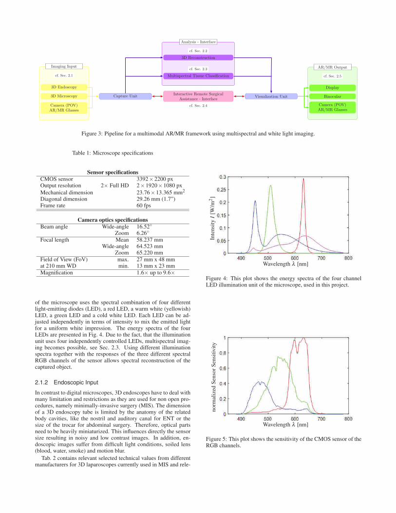
Our proposed system consists of five major modules. Fig. 3 de-picts the complete system architecture. Two in-/output modules
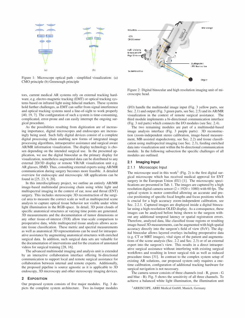
Figure 2: Digital binocular and high resolution imaging unit of mi-croscopic head.
(I/O) handle the multimodal image input (Fig. 3 yellow parts, seeSec. 2.1) and output (Fig. 3 green parts, see Sec. 2.5) and its AR/MRvisualization in the context of remote surgical assistance. Thethird module implements a bi-directional communication interface(Fig. 3 red parts) which connects the I/O modules (see Sec. 2.4).
The two remaining modules are part of a multimodal-basedimage analysis interface (Fig. 3 purple parts): 3D reconstruc-tion (zoom-independent stereo calibration, image-based measure-ment, MR-assisted stapedectomy, see Sec. 2.2) and tissue classifi-cation using multispectral imaging (see Sec. 2.3), feeding enricheddata into visualization unit within the bi-directional communicationmodule. In the following subsection the specific challenges of allmodules are outlined.
2.1 Imaging Input
2.1.1 Microscopic Input
The microscope used in this work1 (Fig. 2) is the first digital sur-gical microscope which has received medical approval for ENTsurgery in the European Union (EU) [1]. The microscopic speci-fications are presented in Tab. 1. The images are captured by a highresolution digital camera sensor (2×1920×1080) with 60 fps. Theoptical system is motor controlled allowing an accurate and pre-cise positioning of specific focal lengths and focus positions whichis crucial for a high accuracy zoom-independent calibration, seeSec. 2.2.1. Captured images are displayed inside a digital binocu-lar using a high-resolution OLED display. As a consequence, theseimages can be analyzed before being shown to the surgeon with-out any additional temporal latency or spatial registration errors.Therefore, analyzed data, like classified tissue regions or resultingimage-based 3D measurements, can be augmented with high spatialaccuracy directly into the surgeon’s field of view (FoV). The dig-ital binocular allows layered overlays including preoperative data(e.g. CT or MRT images), vital signs of the patient and augmenta-tions of the scene analysis (Sec. 2.2 and Sec. 2.3) or of an externalexpert into the surgeon’s view. This results in a direct intraoper-ative surgical assistance without interfering with existing surgicalworkflows and resulting in lower surgical risk as well as reducedprocedure times [31]. In contrast to the complex system setup ofexisting AR solutions, our proposed system only requires a one-time calibration, configuration of additional tracking hardware forsurgical navigation is not necessary.
The camera sensor consists of three channels (red - R, green - Gand blue - B). Fig. 5 shows the sensitivity of all three channels. Toachieve a balanced white light illumination, the illumination unit
1ARRISCOPE, ARRI Medical GmbH, Munich, Germany
Imaging Input AR/MR Output
Analysis - Interface
cf. Sec. 2.1
3D Endoscopy
3D Microscopy
Camera (POV)AR/MR Glasses
Capture Unit Interactive Remote SurgicalAssistance - Interface
cf. Sec. 2.4
Visualization Unit Binocular
Display
cf. Sec. 2.5
Camera (POV)AR/MR Glasses
Multispectral Tissue Classification
cf. Sec. 2.3
3D Reconstruction
cf. Sec. 2.2
Figure 3: Pipeline for a multimodal AR/MR framework using multispectral and white light imaging.
Table 1: Microscope specifications
Sensor specifications
CMOS sensor 3392×2200 pxOutput resolution 2× Full HD 2×1920×1080 pxMechanical dimension 23.76×13.365 mm2
Diagonal dimension 29.26 mm (1.7”)Frame rate 60 fps
Camera optics specifications
Beam angle Wide-angle 16.52◦
Zoom 6.26◦
Focal length Mean 58.237 mmWide-angle 64.523 mm
Zoom 65.220 mmField of View (FoV) max. 27 mm x 48 mmat 210 mm WD min. 13 mm x 23 mmMagnification 1.6× up to 9.6×
of the microscope uses the spectral combination of four differentlight-emitting diodes (LED), a red LED, a warm white (yellowish)LED, a green LED and a cold white LED. Each LED can be ad-justed independently in terms of intensity to mix the emitted lightfor a uniform white impression. The energy spectra of the fourLEDs are presented in Fig. 4. Due to the fact, that the illuminationunit uses four independently controlled LEDs, multispectral imag-ing becomes possible, see Sec. 2.3. Using different illuminationspectra together with the responses of the three different spectralRGB channels of the sensor allows spectral reconstruction of thecaptured object.
2.1.2 Endoscopic Input
In contrast to digital microscopes, 3D endoscopes have to deal withmany limitation and restrictions as they are used for non open pro-cedures, namely minimally-invasive surgery (MIS). The dimensionof a 3D endoscopy tube is limited by the anatomy of the relatedbody cavities, like the nostril and auditory canal for ENT or thesize of the trocar for abdominal surgery. Therefore, optical partsneed to be heavily miniaturized. This influences directly the sensorsize resulting in noisy and low contrast images. In addition, en-doscopic images suffer from difficult light conditions, soiled lens(blood, water, smoke) and motion blur.
Tab. 2 contains relevant selected technical values from differentmanufacturers for 3D laparoscopes currently used in MIS and rele-
Wavelength λ [nm]
Inte
nsit
yI
[W/m
2]
Figure 4: This plot shows the energy spectra of the four channelLED illumination unit of the microscope, used in this project.
Wavelength λ [nm]
norm
aliz
edS
enso
rS
ensi
tivi
ty
Figure 5: This plot shows the sensitivity of the CMOS sensor of theRGB channels.
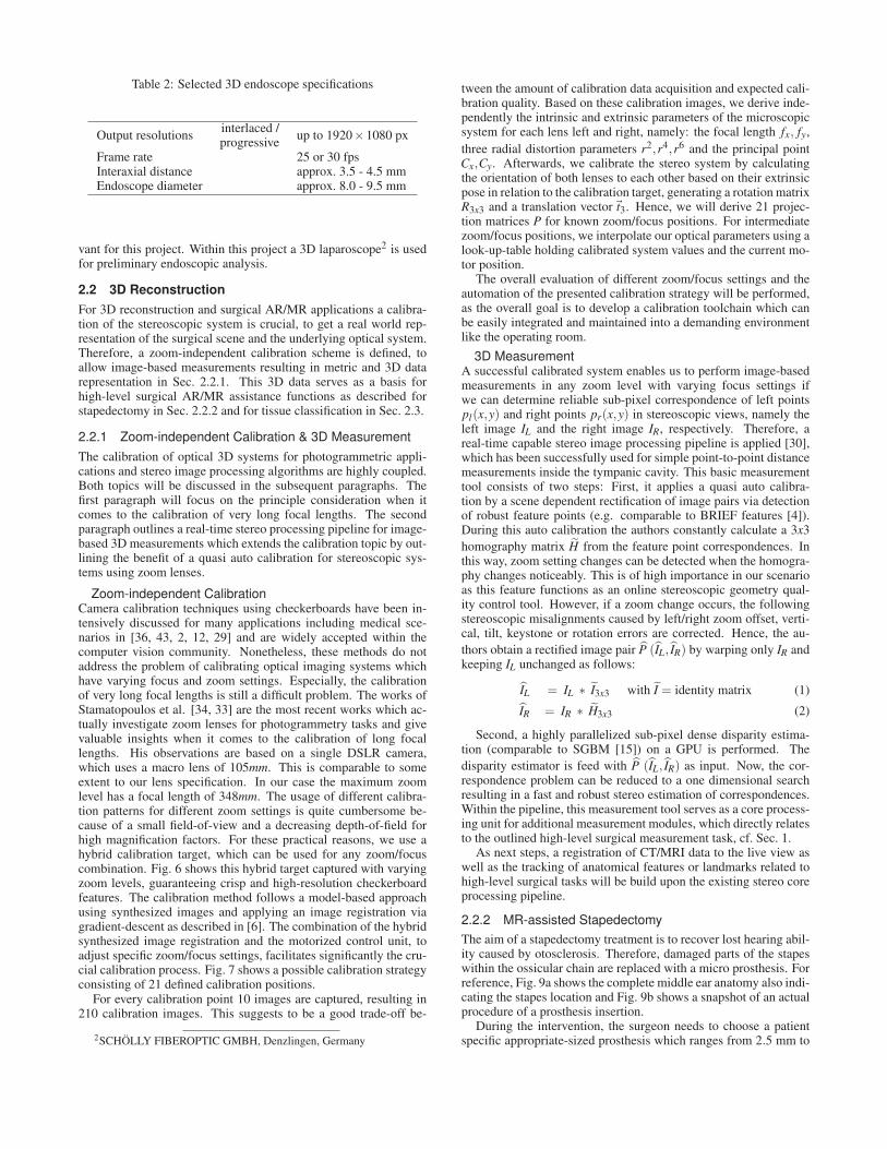
Table 2: Selected 3D endoscope specifications
Output resolutionsinterlaced /
up to 1920×1080 pxprogressive
Frame rate 25 or 30 fpsInteraxial distance approx. 3.5 - 4.5 mmEndoscope diameter approx. 8.0 - 9.5 mm
vant for this project. Within this project a 3D laparoscope2 is usedfor preliminary endoscopic analysis.
2.2 3D Reconstruction
For 3D reconstruction and surgical AR/MR applications a calibra-tion of the stereoscopic system is crucial, to get a real world rep-resentation of the surgical scene and the underlying optical system.Therefore, a zoom-independent calibration scheme is defined, toallow image-based measurements resulting in metric and 3D datarepresentation in Sec. 2.2.1. This 3D data serves as a basis forhigh-level surgical AR/MR assistance functions as described forstapedectomy in Sec. 2.2.2 and for tissue classification in Sec. 2.3.
2.2.1 Zoom-independent Calibration & 3D Measurement
The calibration of optical 3D systems for photogrammetric appli-cations and stereo image processing algorithms are highly coupled.Both topics will be discussed in the subsequent paragraphs. Thefirst paragraph will focus on the principle consideration when itcomes to the calibration of very long focal lengths. The secondparagraph outlines a real-time stereo processing pipeline for image-based 3D measurements which extends the calibration topic by out-lining the benefit of a quasi auto calibration for stereoscopic sys-tems using zoom lenses.
Zoom-independent CalibrationCamera calibration techniques using checkerboards have been in-tensively discussed for many applications including medical sce-narios in [36, 43, 2, 12, 29] and are widely accepted within thecomputer vision community. Nonetheless, these methods do notaddress the problem of calibrating optical imaging systems whichhave varying focus and zoom settings. Especially, the calibrationof very long focal lengths is still a difficult problem. The works ofStamatopoulos et al. [34, 33] are the most recent works which ac-tually investigate zoom lenses for photogrammetry tasks and givevaluable insights when it comes to the calibration of long focallengths. His observations are based on a single DSLR camera,which uses a macro lens of 105mm. This is comparable to someextent to our lens specification. In our case the maximum zoomlevel has a focal length of 348mm. The usage of different calibra-tion patterns for different zoom settings is quite cumbersome be-cause of a small field-of-view and a decreasing depth-of-field forhigh magnification factors. For these practical reasons, we use ahybrid calibration target, which can be used for any zoom/focuscombination. Fig. 6 shows this hybrid target captured with varyingzoom levels, guaranteeing crisp and high-resolution checkerboardfeatures. The calibration method follows a model-based approachusing synthesized images and applying an image registration viagradient-descent as described in [6]. The combination of the hybridsynthesized image registration and the motorized control unit, toadjust specific zoom/focus settings, facilitates significantly the cru-cial calibration process. Fig. 7 shows a possible calibration strategyconsisting of 21 defined calibration positions.
For every calibration point 10 images are captured, resulting in210 calibration images. This suggests to be a good trade-off be-
2SCHÖLLY FIBEROPTIC GMBH, Denzlingen, Germany
tween the amount of calibration data acquisition and expected cali-bration quality. Based on these calibration images, we derive inde-pendently the intrinsic and extrinsic parameters of the microscopicsystem for each lens left and right, namely: the focal length fx, fy,three radial distortion parameters r2,r4,r6 and the principal pointCx,Cy. Afterwards, we calibrate the stereo system by calculatingthe orientation of both lenses to each other based on their extrinsicpose in relation to the calibration target, generating a rotation matrixR3x3 and a translation vector~t3. Hence, we will derive 21 projec-tion matrices P for known zoom/focus positions. For intermediatezoom/focus positions, we interpolate our optical parameters using alook-up-table holding calibrated system values and the current mo-tor position.
The overall evaluation of different zoom/focus settings and theautomation of the presented calibration strategy will be performed,as the overall goal is to develop a calibration toolchain which canbe easily integrated and maintained into a demanding environmentlike the operating room.
3D MeasurementA successful calibrated system enables us to perform image-basedmeasurements in any zoom level with varying focus settings ifwe can determine reliable sub-pixel correspondence of left pointspl(x,y) and right points pr(x,y) in stereoscopic views, namely theleft image IL and the right image IR, respectively. Therefore, areal-time capable stereo image processing pipeline is applied [30],which has been successfully used for simple point-to-point distancemeasurements inside the tympanic cavity. This basic measurementtool consists of two steps: First, it applies a quasi auto calibra-tion by a scene dependent rectification of image pairs via detectionof robust feature points (e.g. comparable to BRIEF features [4]).During this auto calibration the authors constantly calculate a 3x3homography matrix H from the feature point correspondences. Inthis way, zoom setting changes can be detected when the homogra-phy changes noticeably. This is of high importance in our scenarioas this feature functions as an online stereoscopic geometry qual-ity control tool. However, if a zoom change occurs, the followingstereoscopic misalignments caused by left/right zoom offset, verti-cal, tilt, keystone or rotation errors are corrected. Hence, the au-thors obtain a rectified image pair P (IL, IR) by warping only IR andkeeping IL unchanged as follows:
IL = IL ∗ I3x3 with I = identity matrix (1)
IR = IR ∗ H3x3 (2)
Second, a highly parallelized sub-pixel dense disparity estima-tion (comparable to SGBM [15]) on a GPU is performed. Thedisparity estimator is feed with P (IL, IR) as input. Now, the cor-respondence problem can be reduced to a one dimensional searchresulting in a fast and robust stereo estimation of correspondences.Within the pipeline, this measurement tool serves as a core process-ing unit for additional measurement modules, which directly relatesto the outlined high-level surgical measurement task, cf. Sec. 1.
As next steps, a registration of CT/MRI data to the live view aswell as the tracking of anatomical features or landmarks related tohigh-level surgical tasks will be build upon the existing stereo coreprocessing pipeline.
2.2.2 MR-assisted Stapedectomy
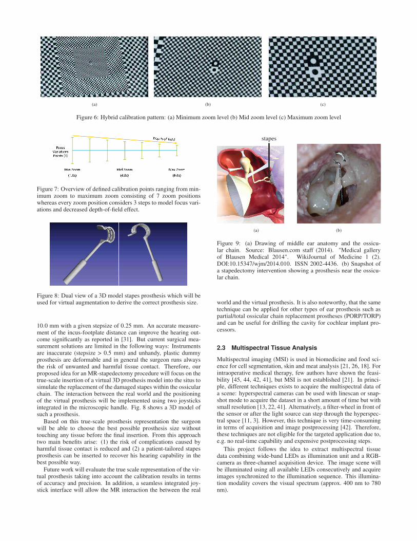
The aim of a stapedectomy treatment is to recover lost hearing abil-ity caused by otosclerosis. Therefore, damaged parts of the stapeswithin the ossicular chain are replaced with a micro prosthesis. Forreference, Fig. 9a shows the complete middle ear anatomy also indi-cating the stapes location and Fig. 9b shows a snapshot of an actualprocedure of a prosthesis insertion.
During the intervention, the surgeon needs to choose a patientspecific appropriate-sized prosthesis which ranges from 2.5 mm to
(a) (b) (c)
Figure 6: Hybrid calibration pattern: (a) Minimum zoom level (b) Mid zoom level (c) Maximum zoom level
Figure 7: Overview of defined calibration points ranging from min-imum zoom to maximum zoom consisting of 7 zoom positionswhereas every zoom position considers 3 steps to model focus vari-ations and decreased depth-of-field effect.
Figure 8: Dual view of a 3D model stapes prosthesis which will beused for virtual augmentation to derive the correct prosthesis size.
10.0 mm with a given stepsize of 0.25 mm. An accurate measure-ment of the incus-footplate distance can improve the hearing out-come significantly as reported in [31]. But current surgical mea-surement solutions are limited in the following ways: Instrumentsare inaccurate (stepsize > 0.5 mm) and unhandy, plastic dummyprosthesis are deformable and in general the surgeon runs alwaysthe risk of unwanted and harmful tissue contact. Therefore, ourproposed idea for an MR-stapedectomy procedure will focus on thetrue-scale insertion of a virtual 3D prosthesis model into the situs tosimulate the replacement of the damaged stapes within the ossicularchain. The interaction between the real world and the positioningof the virtual prosthesis will be implemented using two joysticksintegrated in the microscopic handle. Fig. 8 shows a 3D model ofsuch a prosthesis.
Based on this true-scale prosthesis representation the surgeonwill be able to choose the best possible prosthesis size withouttouching any tissue before the final insertion. From this approachtwo main benefits arise: (1) the risk of complications caused byharmful tissue contact is reduced and (2) a patient-tailored stapesprosthesis can be inserted to recover his hearing capability in thebest possible way.
Future work will evaluate the true scale representation of the vir-tual prosthesis taking into account the calibration results in termsof accuracy and precision. In addition, a seamless integrated joy-stick interface will allow the MR interaction the between the real
stapes
(a) (b)
Figure 9: (a) Drawing of middle ear anatomy and the ossicu-lar chain. Source: Blausen.com staff (2014). "Medical galleryof Blausen Medical 2014". WikiJournal of Medicine 1 (2).DOI:10.15347/wjm/2014.010. ISSN 2002-4436. (b) Snapshot ofa stapedectomy intervention showing a prosthesis near the ossicu-lar chain.
world and the virtual prosthesis. It is also noteworthy, that the sametechnique can be applied for other types of ear prosthesis such aspartial/total ossicular chain replacement prostheses (PORP/TORP)and can be useful for drilling the cavity for cochlear implant pro-cessors.
2.3 Multispectral Tissue Analysis
Multispectral imaging (MSI) is used in biomedicine and food sci-ence for cell segmentation, skin and meat analysis [21, 26, 18]. Forintraoperative medical therapy, few authors have shown the feasi-bility [45, 44, 42, 41], but MSI is not established [21]. In princi-ple, different techniques exists to acquire the multispectral data ofa scene: hyperspectral cameras can be used with linescan or snap-shot mode to acquire the dataset in a short amount of time but withsmall resolution [13, 22, 41]. Alternatively, a filter-wheel in front ofthe sensor or after the light source can step through the hyperspec-tral space [11, 3]. However, this technique is very time-consumingin terms of acquisition and image postprocessing [42]. Therefore,these techniques are not eligible for the targeted application due to,e.g. no real-time capability and expensive postprocessing steps.
This project follows the idea to extract multispectral tissuedata combining wide-band LEDs as illumination unit and a RGB-camera as three-channel acquisition device. The image scene willbe illuminated using all available LEDs consecutively and acquireimages synchronized to the illumination sequence. This illumina-tion modality covers the visual spectrum (approx. 400 nm to 780nm).
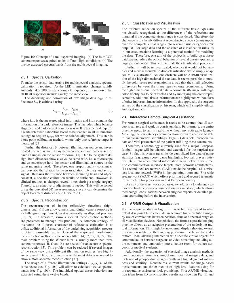
(a) (b)
Figure 10: Concept of a multispectral imaging. (a) The four RGBcamera responses acquired under different light conditions. (b) Thetwelve extracted spectral bands from the multispectral imaging.
2.3.1 Spectral Calibration
To make the sensor data usable for multispectral analysis, spectralcalibration is required. As the LED illumination changes rapidlyand only takes 200 ms for a complete sequence, it is supposed thatall RGB responses include exactly the same view.
The denoising and conversion of raw image data Iraw to re-flectance Ires is achieved using
Ires =Iraw − Idark
Iwhite − Idark
, (3)
where Iraw is the measured pixel information and Idark contains theinformation of a dark reference image. This includes white balancealignment and dark current correction as well. This method requiresa white reference calibration board to be scanned in all illuminationsettings to acquire Iwhite for white balance alignment. This step isa one point calibration method, where only one reference target ismeasured [27].
Further, the distances δ1 between illumination source and inves-tigated surface as well as δ2 between surface and camera sensorhave an impact on the sensor response [41]. Due to the system de-sign, both distances show always the same ratio, i.e. a microscopeand an endoscope hold the sensor and illumination source in thesame mounting head. Therefore, one proportionality constant α
can describe the relation between irradiation intensity and sensorsignal. Remains the distance between mounting head and objectconstant, a one-time calibration would be sufficient. However, inclinical routine, α changes several times during a single surgery.Therefore, an adaptive α adjustment is needed. This will be solvedusing the described 3D measurements, since it can determine theobject to camera distances δ , c.f. Sec. 2.2.1.
2.3.2 Spectral Reconstruction
The reconstruction of in-situ reflectivity functions (high-dimensionally) from a low-dimensional digital camera response isa challenging requirement, as it is generally an ill-posed problem[38, 39]. In literature, various spectral reconstruction methodsare presented to manage this problem. A common strategy ofovercome the ill-posed character of reflectance estimation is toutilize additional information of the underlying acquisition processto obtain reasonable results. One of the major and mostly usedreconstruction methods is the Wiener filter [14, 32, 35, 38, 39]. Themain problem using the Wiener filter is, usually more than threecamera responses (R, G and B) are needed for an accurate spectralreconstruction [5]. This problem can be reduced if several imagesof the same view using different illumination settings (see Fig. 4)are acquired. Thus, the dimension of the input data is increased toallow a more accurate reconstruction [37].
The usage of different illumination settings I1, I2, I3, I4 of thesame scene (see Fig. 10a) will allow to calculate twelve spectralbands (see Fig. 10b). The individual optical tissue behaviors areextracted using these twelve bands.
2.3.3 Classification and Visualization
The different reflection spectra of the different tissue types arenot visually recognized, as the differences of the reflections aremarginal if the complete visual range is considered. Therefore, thechallenge is to classify different reconstructed spectra (many inputsover the complete visual range) into several tissue categories (fewoutputs). For large data and the absence of classification rules, asin our case, machine learning is a potential method for modelingthe data. Therefore, one aim of the project is to build up a tissuedatabase including the optical behavior of several tissue types and alarge patient cohort. This will facilitate the classification problem.
Further, it will be is investigated, whether it would not be sim-pler and more reasonable to drop classification while simply adaptAR/MR visualization. As, one obstacle will be AR/MR visualiza-tion of the high dimensional tissue data, it seems possible to mod-ify the color space representation in a way that the small reflectiondifferences between the tissue types emerge prominently. Usingthe high dimensional spectral data, a normal RGB-image with highcolor-fidelity has to be extracted and by modifying the color repre-sentation, additional tissue information can highlighted without lossof other important image information. In this approach, the surgeonarrives on the classification on his own, which will simplify ethicaland legal impacts.
2.4 Interactive Remote Surgical Assistance
For remote surgical assistance, it needs to be assured that all sur-geons can rely and work on consistent data. Furthermore, the entirepipeline needs to run in real-time without any noticeable latency.Meaning, the low-latency communication software needs to be ableto handle interactive scribblings, large 3D data sets, preoperativedata and vital parameters of the patient fulfilling these constraints.
Therefore, a technology currently used for a major Europeanfootball league will be adapted and extended for the surgical usecase. So far, this system transmits de-centralized live data of gamestatistics (e.g. game score, game highlights, football player statis-tics, etc.) into a centralized information news ticker in real-time.The communication interface targets three network architectures:(1) a wired local are network (LAN) inside the hospital, (2) a wire-less local are network (WiFi) in the operating room and (3) a widearea network (WAN) which offers prioritized and secured telematicinfrastructure for physicians in that European country.
For any of these network scenarios, we address a low-latency in-teractive bi-directional communication user interface, which allowsmedicolegal consultations between surgical experts or detailed pa-tient counseling before the intervention.
2.5 AR/MR Output & Visualization
For the output module in Fig. 3, it has to be investigated to whatextent it is possible to calculate an accurate high-resolution imageby use of correlations between position, time and spectral range onall visualization devices. Nonetheless, the format agnostic imagingpipeline allows us an adaptive presentation of the underlying mu-tual information. This might be an external display showing overallinformation related to the ongoing procedure, the binocular and aremote HMD allowing interaction with specific virtual objects forcommunication between surgeons or video streaming including au-dio comments and annotation into a lecture room for trainee sur-geons or medical students.
Additionally, the expansion of classical image analysis methodslike image registration, tracking of multispectral imaging data, andinclusion of preoperative images results in a high degree of robust-ness and stability. Nonetheless, current results for image-basedmeasurements and the extraction of high-level features using forintraoperative assistance look promising. First AR/MR visualiza-tion ideas from 3D reconstruction results are shown in Fig. 11 and
(a) (b) (c)
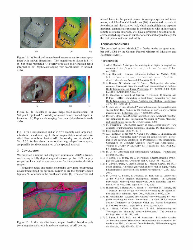
Figure 11: (a) Results of image-based measurement for a test spec-imen with known dimensions. The magnification factor is 8.1×(b) Sub-pixel registered AR overlay of related color-encoded depthinformation. (c) Depth scale ranging from near (blueish) to far (red-dish).
(a) (b) (c)
Figure 12: (a) Results of in-vivo image-based measurement (b)Sub-pixel registered AR overlay of related color-encoded depth in-formation. (c) Depth scale ranging from near (blueish) to far (red-dish).
Fig. 12 for a test specimen and an in-vivo example with large mag-nification. In addition, Fig. 13 shows augmentation results of clas-sified blood vessels as classical AR color overlay. As introduced inSec. 2.3.3, further visualization options, e.g. adapted color space,are possible for the presentation of the spectral analysis.
3 CONCLUSION
We proposed a unique and integrated multimodal AR/MR frame-work using a fully digital surgical microscope for ENT surgerysupporting local and remote assistance for intraoperative decisionsupport.
The technological and market potential is very large for a productdevelopment based on our idea. Surgeries are the primary source(up to 50%) of errors in the health care sector [8]. These errors and
Figure 13: In this visualization example classified blood vessels(vein in green and arteria in red) are presented as AR overlay.
related harm to the patient causes follow-up surgeries and treat-ments, which lead to additional costs [10]. A volumetric tissue dif-ferentiation and visualization tool, which can highlight and separateimportant anatomical structures in combination with an interactiveremote assistance interface, will have a promising potential to de-crease related expenses and number of accidental organ damage forthe best patient outcome and safety.
ACKNOWLEDGEMENTS
The described project MultiARC is funded under the grant num-ber 16SV8061 by the German Federal Ministry of Education andResearch (BMBF).
REFERENCES
[1] ARRI Medical. Arriscope - the next step in all digital 3d surgical mi-croscopy. http://www.arrimedical.com,Accessed, 09 Jan-uary 2019.
[2] J.-Y. Bouguet. Camera calibration toolbox for Matlab, 2008.http://www.vision.caltech.edu/bouguetj/calib_
doc/index.htm,Accessed, 09 January 2019.[3] J. Brauers, N. Schulte, and T. Aach. Multispectral filter-wheel
cameras: Geometric distortion model and compensation algorithms.IEEE Transactions on Image Processing, 17(12):2368–2380, 2008.[doi:10.1109/TIP.2008.2006605].
[4] M. Calonder, V. Lepetit, M. Ozuysal, T. Trzcinski, C. Strecha, andP. Fua. BRIEF: Computing a local binary descriptor very fast.IEEE Transactions on Pattern Analysis and Machine Intelligence,34(7):1281–1298, 2012.
[5] S. Chen and Q. Liu. Modified Wiener estimation of diffuse reflectancespectra from RGB values by the synthesis of new colors for tissuemeasurements. J. Biomed. Opt., 17(3):030501, 2012.
[6] P. Eisert. Model-based Camera Calibration Using Analysis by Synthe-sis Techniques. In Proc. International Workshop on Vision, Modeling,and Visualization, pages 307–314, Erlangen, 2002.
[7] M. Feuerstein. Augmented reality in laparoscopic surgery. Newconcepts for intraoperative multimodal imaging. TU München, 2007.
[8] Frost and Sullivan. 9837-54, 2014.[9] J. J. Fuertes, F. López-Mir, V. Naranjo, M. Ortega, E. Villanueva, and
M. Alcañiz. Augmented reality system for keyhole surgery - perfor-mance and accuracy validation. In Proceedings of the InternationalConference on Computer Graphics Theory and Applications -Volume 1: GRAPP, (VISIGRAPP 2011), pages 273–279. INSTICC,SciTePress, 2011.
[10] D. G. für Orthopädie und orthopädische Chirurgie. Faktencheckgesundheit, 2013.
[11] Y. Garini, I. T. Young, and G. McNamara. Spectral Imaging: Princi-ples and Applications. Cytometry Part A, 69(A):735–747, 2006.
[12] S. Garrido-Jurado, R. Muñoz-Salinas, F. J. Madrid-Cuevas, and M. J.Marín-Jiménez. Automatic generation and detection of highly reliablefiducial markers under occlusion. Pattern Recognition, 47:2280–2292,2014.
[13] B. Geelen, C. Blanch, P. Gonzalez, N. Tack, and A. Lambrechts.A tiny VIS-NIR snapshot multispectral camera. In AdvancedFabrication Technologies for Micro/Nano Optics Photonics VIII, vol-ume 9374 of Proc. SPIE, pages 937414–1, 2015.
[14] H. Haneishi, T. Hasegawa, A. Hosoi, Y. Yokoyama, N. Tsumura, andY. Miyake. System design for accurately estimating the spectral re-flectance of art paintings. Appl. Opt., 39(35):6621–6632, 2000.
[15] H. Hirschmuller. Accurate and efficient stereo processing by semi-global matching and mutual information. In 2005 IEEE ComputerSociety Conference on Computer Vision and Pattern Recognition(CVPR’05), volume 2, pages 807–814 vol. 2, June 2005.
[16] A. J. Hung, J. Chen, A. Shah, and I. S. Gill. Telementoring andTelesurgery for Minimally Invasive Procedures. The Journal ofUrology, 199(2):355–369, 2018.
[17] J. Ilgner, J. J.-H. Park, and M. Westhofen. Praktische Aspektezur hochauflösenden Stereovideo-Dokumentation intraoperativer Be-funde in der Hals-, Nasen- und Ohrenheilkunde. Bildverarbeitung fürdie Medizin, 14(1):450–454, 2010.
[18] M. Kamruzzaman, D. F. Barbin, G. ElMasry, D.-W. Sun, and P. Allen.Potential of hyperspectral imaging and pattern recognition for catego-rization and authentication of red meat. Innovative Food Science andEmerging Technologies, 16:316–325, 2012.
[19] W. S. Khor, B. Baker, K. Amin, A. Chan, K. Patel, and J. Wong. Aug-mented and virtual reality in surgery - the digital surgical environment:applications, limitations and legal pitfalls. Annals of TranslationalMedicine, 4(23):454–454, 2016.
[20] F. López-Mir, V. Naranjo, J. J. Fuertes, M. Alcañiz, J. Bueno, andE. Pareja. Design and validation of an augmented reality systemfor laparoscopic surgery in a real environment. BioMed ResearchInternational, 2013, 2013.
[21] G. Lu and B. Fei. Medical hyperspectral imaging: a re-view. Journal of Biomedical Optics, 19(1):10901, 2014.[doi:10.1117/1.JBO.19.1.010901].
[22] A. S. Luthman, S. Dumitru, I. Quiros-Gonzalez, J. Joseph, and S. E.Bohndiek. Fluorescence hyperspectral imaging (fHSI) using a spec-trally resolved detector array. Journal of Biophotonics, 10(6):840–853, 2017.
[23] L. Maier-Hein. Optical techniques for 3d surface reconstruction incomputer-assisted laparoscopic surgery. Medical Image Analysis,17(974), 2013.
[24] MediClin. Struktur und Leistungen der Klinik für Chirurgie. Techni-cal report, MediClin Müritz-Klinikum, Waren (Müritz), 2007.
[25] A. Meola, F. Cutolo, M. Carbone, F. Cagnazzo, M. Ferrari, andV. Ferrari. Augmented reality in neurosurgery: a systematic review.Neurosurgical Review, 40(4):537–548, 2017.
[26] J. Pichette, A. Laurence, L. Angulo, F. Lesage, A. Bouthillier,D. K. Nguyen, and F. Leblond. Intraoperative video-rate hemo-dynamic response assessment in human cortex using snapshot hy-perspectral optical imaging. Neurophotonics, 3(4):045003, 2016.[doi:10.1117/1.NPh.3.4.045003].
[27] G. Polder, G. W. van der Heijden, L. P. Keizer, and I. T. Young. Cali-bration and characterisation of imaging spectrographs. Journal of nearInfrared Spectroscopy, 11(3):193–210, 2003.
[28] T. A. Ponsky, M. Schwachter, J. Parry, S. Rothenberg, and K. M.Augestad. Telementoring: the surgical tool of the future. EuropeanJournal of Pediatric Surgery, 24(04):287–294, 2014.
[29] J.-C. Rosenthal, N. Gard, A. Schneider, and P. Eisert. Kalibrierungstereoskopischer Systeme für medizinische Messaufgaben. In 16thAnnual CURAC Conference. PZH-Verlag, 2017.
[30] J.-C. Rosenthal, N. Gard, A. Schneider, and P. Eisert. Microscopicimage-based determination of stapes prosthesis length. In ConferenceProceedings 32nd Int. Congress of Computer Assisted Radiology andSurgery, CARS, pages 59–60, June 2018.
[31] I. Saliba and C.Marchica. The Relationship between Stapes ProsthesisLength and Rate of Stapedectomy Success. Clin Med Insights EarNose Throat, 8(23), 2015.
[32] N. Shimano, K. Terai, and M. Hironaga. Recovery of spectral re-flectances of objects being imaged by multispectral cameras. J. Opt.Soc. Am. A, 24(10):3211–3219, 2007.
[33] C. Stamatopoulos and C. Fraser. Calibration of long focal length cam-eras in close range photogrammetry. The Photogrammetric Record,26:339–360, 2011.
[34] C. Stamatopoulos, C. Fraser, and S. Cronk. On the self-calibration oflong focal length lenses. International Archives of Photogrammetry,Remote Sensing and Spatial Information Sciences, 38(Part 5), 2010.
[35] P. T. Stigell, K. Miyata, and M. Hauta-Kasari. Wiener estima-tion method in estimating of spectral reflectance from RGB images.Pattern Recognit. Image Anal., 17(2):233–242, 2007.
[36] R. Tsai. A versatile camera calibration technique for high-accuracy 3dmachine vision metrology using off-the-shelf TV cameras and lenses.IEEE Journal on Robotics and Automation, 3(4):323–344, Aug. 1987.
[37] P. Urban, M. Desch, K. Happel, and D. Spiehl. Recovering camerasensitivities using target-based reflectances captured under multipleled-illuminations. In Proc. of Workshop on Color Image Processing,pages 9–16, 2010.
[38] P. Urban, M. R. Rosen, and R. S. Berns. A spatially adaptive wienerfilter for reflectance estimation. In Proc. IS T/SID Color ImagingConf., volume 16, pages 279–284, 2008.
[39] P. Urban, M. R. Rosen, and R. S. Berns. Spectral image reconstructionusing an edge preserving spatio-spectral Wiener estimation. J. Opt.Soc. Am. A, 26(8):1865–1875, 2009.
[40] P. Vávra, J. Roman, P. Zonca, P. Ihnát, M. Nemec, J. Kumar, N. Habib,and A. El-Gendi. Recent Development of Augmented Reality inSurgery: A Review. Journal of Healthcare Engineering, pages 1–9,2017.
[41] E. L. Wisotzky, B. Kossack, F. C. Uecker, P. Arens, S. Dommerich,A. Hilsmann, and P. Eisert. Validation of two techniques for intraop-erative hyperspectral human tissue determination. In Proceedings ofSPIE, volume 10951, page 1095171, 2019.
[42] E. L. Wisotzky, F. C. Uecker, P. Arens, S. Dommerich, A. Hilsmann,and P. Eisert. Intraoperative hyperspectral determination of humantissue properties. Journal of Biomedical Optics, 23(9):091409, 2018.
[43] Z. Zhang. Flexible camera calibration by viewing a plane from un-known orientations. In Proceedings of the Seventh IEEE InternationalConference on Computer Vision, Kerkyra, 1999.
[44] K. J. Zuzak, R. P. Francis, E. F. Wehner, J. Smith, M. Litorja, D. W.Allen, C. Tracy, J. Cadeddu, and E. Livingston. Hyperspectral imag-ing utilizing lctf and dlp technology for surgical and clinical applica-tions. In Design and Quality for Biomedical Technologies II, volume7170, page 71700C. International Society for Optics and Photonics,2009.
[45] K. J. Zuzak, M. D. Schaeberle, E. N. Lewis, and I. W. Levin. Visiblereflectance hyperspectral imaging: characterization of a noninvasive,in vivo system for determining tissue perfusion. Analytical chemistry,74(9):2021–2028, 2002.


![[DEMO] On-Site Augmented Collaborative Architecture Visualizationfar.in.tum.de/pub/toennis2014ismarArch/toennis2014ismarArch.pdf · IEEE International Symposium on Mixed and Augmented](https://static.fdocuments.fr/doc/165x107/5f0b5b887e708231d4301ea8/demo-on-site-augmented-collaborative-architecture-ieee-international-symposium.jpg)