MALDI Source Hardware Manual Version C · 2017-09-12 · L’instrument doit être arrêté et...
104
MALDI Source Hardware Manual 97155-97013 Revision C January 2009
Transcript of MALDI Source Hardware Manual Version C · 2017-09-12 · L’instrument doit être arrêté et...

MALDI Source
Hardware Manual
97155-97013 Revision C January 2009

© 2009 Thermo Fisher Scientific Inc. All rights reserved.
Xcalibur is a registered trademark of Thermo Fisher Scientific Inc. in the United States.
Microsoft and Windows are registered trademarks of Microsoft Corporation in the United States and other countries.
ProteoMass is a registered trademark of Sigma-Aldrich Biotechnology LP and Sigma-Aldrich Co. in the United States and possibly other countries.
LTQ XL and Ion Max are trademarks of Thermo Fisher Scientific Inc.
Kwik-Flange is a trademark of MDC Vacuum Products, LLC. Qiagen is a trademark of Qiagen, Inc.
All other trademarks are the property of Thermo Fisher Scientific Inc. and its subsidiaries.
Thermo Fisher Scientific Inc. provides this document to its customers with a product purchase to use in the product operation. This document is copyright protected and any reproduction of the whole or any part of this document is strictly prohibited, except with the written authorization of Thermo Fisher Scientific Inc.
The contents of this document are subject to change without notice. All technical information in this document is for reference purposes only. System configurations and specifications in this document supersede all previous information received by the purchaser.
Thermo Fisher Scientific Inc. makes no representations that this document is complete, accurate or error-free and assumes no responsibility and will not be liable for any errors, omissions, damage or loss that might result from any use of this document, even if the information in the document is followed properly.
This document is not part of any sales contract between Thermo Fisher Scientific Inc. and a purchaser. This document shall in no way govern or modify any Terms and Conditions of Sale, which Terms and Conditions of Sale shall govern all conflicting information between the two documents.
Release history: Revision A released February 2008; Revision B released September 2008; Revision C released January 2009.
Software Version: Xcalibur 2.1 or earlier, LTQ Series 2.6.0 or earlier
For Research Use Only. Not for use in diagnostic procedures.

Regulatory Compliance
Thermo Fisher Scientific performs complete testing and evaluation of its products to ensure full compliance with applicable domestic and international regulations. When the system is delivered to you, it meets all pertinent electromagnetic compatibility (EMC) and safety standards as described in the next section or sections by product name.
Changes that you make to your system may void compliance with one or more of these EMC and safety standards. Changes to your system include replacing a part or adding components, options, or peripherals not specifically authorized and qualified by Thermo Fisher Scientific. To ensure continued compliance with EMC and safety standards, replacement parts and additional components, options, and peripherals must be ordered from Thermo Fisher Scientific or one of its authorized representatives.
EMC Directive 204/108/EC
EMC compliance has been evaluated by TUV Rheinland of North America.
Low Voltage Safety ComplianceCompliance with safety issues is declared under Thermo Fisher Scientific sole responsibility.This device complies with Low Voltage Directive 2006/95/EC and harmonized standard EN 61010-1:2001.
Safety of Laser ProductsCompliance with laser products is declared under Thermo Fisher Scientific sole responsibility.This device complies with the harmonized standard IEC/EN 60825-1/A2: 2001.
EN 55011: 1998, A1: 1999, A2: 2002 EN 61000-4-3: 2002
EN 61000-3-2: 2000 EN 61000-4-4: 1995, A1: 2000, A2: 2001
EN 61000-3-3: 1995, A1: 2001 EN 61000-4-5: 2001
EN 61326-1: 1998, A2: 2001, A3: 2003 EN 61000-4-6: 2003
EN 61000-4-2: 2001 EN 61000-4-11: 2001
FCC Class A, CFR 47 Part 15: 2006 CISPR 11: 1998, A1:1999, A2:2002

FCC Compliance Statement
Notice on Lifting and Handling ofThermo Scientific Instruments
For your safety, and in compliance with international regulations, the physical handling of this Thermo Fisher Scientific instrument requires a team effort to lift and/or move the instrument. This instrument is too heavy and/or bulky for one person alone to handle safely.
Notice on the Proper Use ofThermo Scientific Instruments
In compliance with international regulations: Use of this instrument in a manner not specified by Thermo Fisher Scientific could impair any protection provided by the instrument.
Notice on the Susceptibility to Electromagnetic Transmissions
Your instrument is designed to work in a controlled electromagnetic environment. Do not use radio frequency transmitters, such as mobile phones, in close proximity to the instrument.
For manufacturing location, see the label on the instrument.
THIS DEVICE COMPLIES WITH PART 15 OF THE FCC RULES. OPERATION IS SUBJECT TO THE FOLLOWING TWO CONDITIONS: (1) THIS DEVICE MAY NOT CAUSE HARMFUL INTERFERENCE, AND (2) THIS DEVICE MUST ACCEPT ANY INTERFERENCE RECEIVED, INCLUDING INTERFERENCE THAT MAY CAUSE UNDESIRED OPERATION.
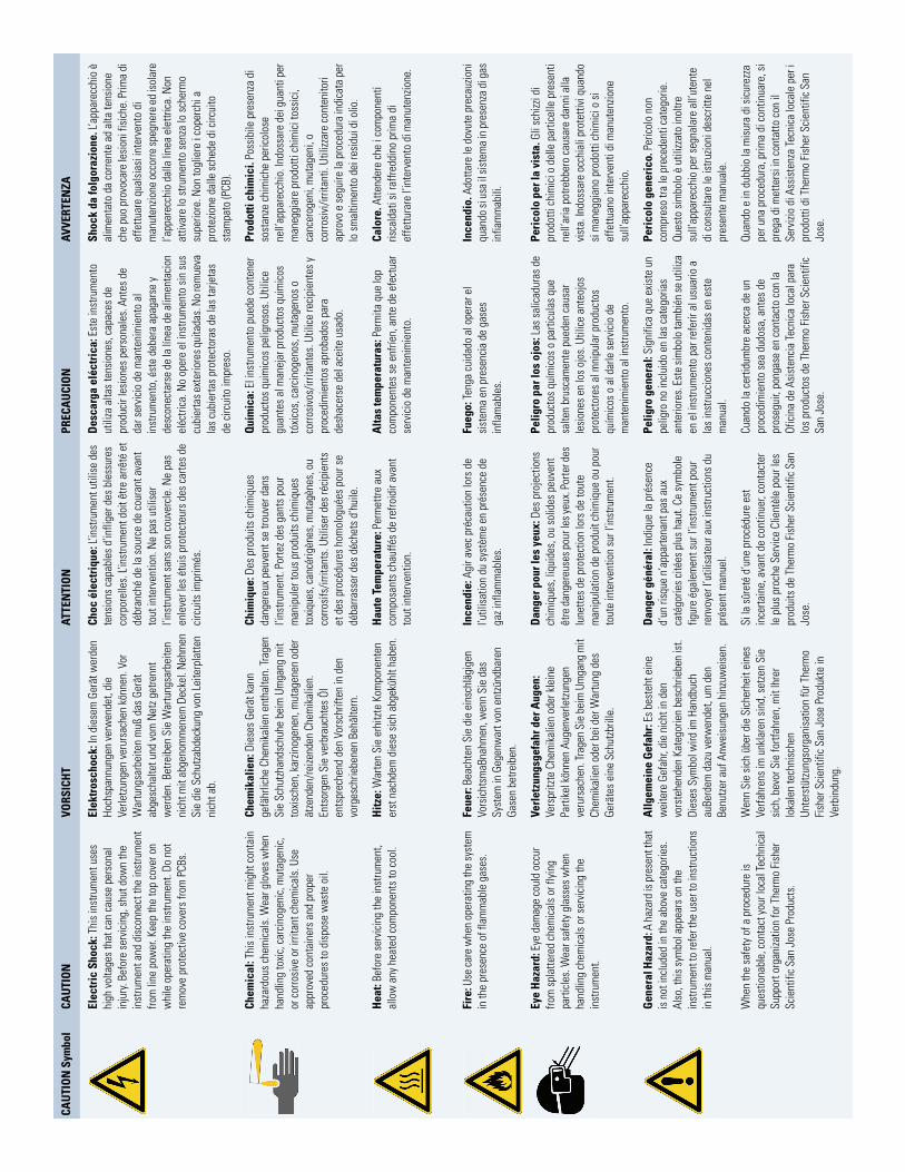
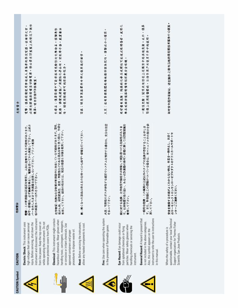
CAUTION Read and understand the various precautionary notes, signs, and symbols contained inside this manual pertaining to the safe use and operation of this product before using the device.
WEEE Compliance
This product is required to comply with the European Union’s Waste Electrical & Electronic Equipment (WEEE) Directive 2002/96/EC. It is marked with the following symbol:
Thermo Fisher Scientific has contracted with one or more recycling or disposal companies in each European Union (EU) Member State, and these companies should dispose of or recycle this product. See www.thermo.com/WEEERoHS for further information on Thermo Fisher Scientific’s compliance with these Directives and the recyclers in your country.
WEEE Konformität
Dieses Produkt muss die EU Waste Electrical & Electronic Equipment (WEEE) Richtlinie 2002/96/EC erfüllen. Das Produkt ist durch folgendes Symbol gekennzeichnet:
Thermo Fisher Scientific hat Vereinbarungen mit Verwertungs-/Entsorgungsfirmen in allen EU-Mitgliedsstaaten getroffen, damit dieses Produkt durch diese Firmen wiederverwertet oder entsorgt werden kann. Mehr Information über die Einhaltung dieser Anweisungen durch Thermo Fisher Scientific, über die Verwerter, und weitere Hinweise, die nützlich sind, um die Produkte zu identifizieren, die unter diese RoHS Anweisung fallen, finden sie unter www.thermo.com/WEEERoHS.

Conformité DEEE
Ce produit doit être conforme à la directive européenne (2002/96/EC) des Déchets d'Equipements Electriques et Electroniques (DEEE). Il est marqué par le symbole suivant:
Thermo Fisher Scientific s'est associé avec une ou plusieurs compagnies de recyclage dans chaque état membre de l’union européenne et ce produit devrait être collecté ou recyclé par celles-ci. Davantage d'informations sur la conformité de Thermo Fisher Scientific à ces directives, les recycleurs dans votre pays et les informations sur les produits Thermo Fisher Scientific qui peuvent aider la détection des substances sujettes à la directive RoHS sont disponibles sur www.thermo.com/WEEERoHS.
CAU
TIO
N S
ymbo
lCA
UTI
ON
VORS
ICH
TAT
TEN
TIO
NPR
ECA
UCIO
NAV
VERT
ENZA
Elec
tric
Sho
ck: T
his
inst
rum
ent u
ses
high
vol
tage
s th
at c
an c
ause
per
sona
l in
jury
. Bef
ore
serv
icin
g, s
hut d
own
the
inst
rum
ent a
nd d
isco
nnec
t the
inst
rum
ent
from
line
pow
er. K
eep
the
top
cove
r on
whi
le o
pera
ting
the
inst
rum
ent.
Do n
ot
rem
ove
prot
ectiv
e co
vers
from
PCB
s.
Elek
tros
choc
k: In
die
sem
Ger
ät w
erde
n Ho
chsp
annu
ngen
ver
wen
det,
die
Verle
tzun
gen
veru
rsac
hen
könn
en. V
or
War
tung
sarb
eite
n m
uß d
as G
erät
ab
gesc
halte
t und
vom
Net
z get
renn
t w
erde
n. B
etre
iben
Sie
War
tung
sarb
eite
n ni
cht m
it ab
geno
mm
enem
Dec
kel.
Neh
men
Si
e di
e Sc
hutz
abde
ckun
g vo
n Le
iterp
latte
n ni
cht a
b.
Choc
éle
ctri
que:
L’in
stru
men
t util
ise
des
tens
ions
cap
able
s d’
infli
ger d
es b
less
ures
co
rpor
elle
s. L’
inst
rum
ent d
oit ê
tre a
rrêté
et
débr
anch
é de
la s
ourc
e de
cou
rant
ava
nt
tout
inte
rven
tion.
Ne
pas
utili
ser
l’ins
trum
ent s
ans
son
couv
ercl
e. N
e pa
s en
leve
r les
étu
is p
rote
cteu
rs d
es c
arte
s de
ci
rcui
ts im
prim
és.
Des
carg
a el
éctr
ica:
Est
e in
stru
men
to
utili
za a
ltas
tens
ione
s, c
apac
es d
e pr
oduc
ir le
sion
es p
erso
nale
s. A
ntes
de
dar s
ervi
cio
de m
ante
nim
ient
o al
in
stru
men
to, é
ste
debe
ra a
paga
rse
y de
scon
ecta
rse
de la
líne
a de
alim
enta
cion
el
éctri
ca. N
o op
ere
el in
stru
men
to s
in s
us
cubi
erta
s ext
erio
res q
uita
das.
No
rem
ueva
la
s cu
bier
tas
prot
ecto
ras
de la
s ta
rjeta
s de
circ
uito
impr
eso.
Shoc
k da
folg
oraz
ione
. L’a
ppar
ecch
io è
al
imen
tato
da
corre
nte
ad a
lta te
nsio
ne
che
puo
prov
ocar
e le
sion
i fis
iche
. Prim
a di
ef
fettu
are
qual
sias
i int
erve
nto
di
man
uten
zione
occ
orre
speg
nere
ed
isol
are
l’app
arec
chio
dal
la li
nea
elet
trica
. Non
at
tivar
e lo
stru
men
to s
enza
lo s
cher
mo
supe
riore
. Non
togl
iere
i co
perc
hi a
pr
otez
ione
dal
le s
ched
e di
circ
uito
st
ampa
to (P
CB).
Chem
ical
: Thi
s in
stru
men
t mig
ht c
onta
in
haza
rdou
s ch
emic
als.
Wea
r glo
ves
whe
n ha
ndlin
g to
xic,
car
cino
geni
c, m
utag
enic
, or
cor
rosi
ve o
r irri
tant
che
mic
als.
Use
ap
prov
ed c
onta
iner
s an
d pr
oper
pr
oced
ures
to d
ispo
se w
aste
oil.
Chem
ikal
ien:
Die
ses
Gerä
t kan
n ge
fähr
liche
Che
mik
alie
n en
thal
ten.
Trag
en
Sie
Schu
tzha
ndsc
huhe
bei
m U
mga
ng m
it to
xisc
hen,
kar
zinog
enen
, mut
agen
en o
der
ätze
nden
/rei
zend
en C
hem
ikal
ien.
En
tsor
gen
Sie
verb
rauc
htes
Öl
ents
prec
hend
den
Vor
schr
iften
in d
en
vorg
esch
riebe
nen
Behä
ltern
.
Chim
ique
: Des
pro
duits
chi
miq
ues
dang
ereu
x pe
uven
t se
trouv
er d
ans
l’ins
trum
ent.
Porte
z des
gan
ts p
our
man
ipul
er to
us p
rodu
its c
him
ique
s to
xiqu
es, c
ancé
rigèn
es, m
utag
ènes
, ou
corro
sifs
/irrit
ants
. Util
iser
des
réci
pien
ts
et d
es p
rocé
dure
s ho
mol
ogué
es p
our s
e dé
barra
sser
des
déc
hets
d’h
uile
.
Quí
mic
a: E
l ins
trum
ento
pue
de c
onte
ner
prod
ucto
s qu
imic
os p
elig
roso
s. U
tilic
e gu
ante
s al
man
ejar
pro
duct
os q
uim
icos
tó
xico
s, c
arci
noge
nos,
mut
agen
os o
co
rrosi
vos/
irrita
ntes
. Util
ice
reci
pien
tes
y pr
oced
imie
ntos
apr
obad
os p
ara
desh
acer
se d
el a
ceite
usa
do.
Prod
otti
chim
ici.
Poss
ibile
pre
senz
a di
so
stan
ze c
him
iche
per
icol
ose
nell’
appa
recc
hio.
Indo
ssar
e de
i gua
nti p
er
man
eggi
are
prod
otti
chim
ici t
ossi
ci,
canc
erog
eni,
mut
agen
i, o
corro
sivi
/irrit
anti.
Util
izzar
e co
nten
itori
apro
vo e
segu
ire la
pro
cedu
ra in
dica
ta p
er
lo s
mal
timen
to d
ei re
sidu
i di o
lio.
Hea
t: Be
fore
ser
vici
ng th
e in
stru
men
t, al
low
any
hea
ted
com
pone
nts
to c
ool.
Hitz
e: W
arte
n Si
e er
hitz
te K
ompo
nent
en
erst
nac
hdem
die
se s
ich
abge
kühl
t hab
en.
Hau
te T
empe
ratu
re: P
erm
ettre
aux
co
mpo
sant
s ch
auffé
s de
refro
idir
avan
t to
ut in
terv
entio
n.
Alta
s te
mpe
ratu
ras:
Per
mita
que
lop
com
pone
ntes
se
enfrí
en, a
nte
de e
fect
uar
serv
icio
de
man
teni
mie
nto.
Calo
re. A
ttend
ere
che
i com
pone
nti
risca
ldat
i si r
affre
ddin
o pr
ima
di
effe
ttura
re l’
inte
rven
to d
i man
uten
zione
.
Fire
: Use
care
whe
n op
erat
ing
the
syst
em
in th
e pr
esen
ce o
f fla
mm
able
gas
es.
Feue
r: Be
acht
en S
ie d
ie e
insc
hläg
igen
Vo
rsic
htsm
aBna
hmen
, wen
n Si
e da
s Sy
stem
in G
egen
war
t von
ent
zünd
bare
n Ga
sen
betre
iben
.
Ince
ndie
: Agi
r ave
c pr
écau
tion
lors
de
l’util
isat
ion
du s
ystè
me
en p
rése
nce
de
gaz i
nfla
mm
able
s.
Fueg
o: Te
nga
cuid
ado
al o
pera
r el
sist
ema
en p
rese
ncia
de
gase
s in
flam
able
s.
Ince
ndio
. Ado
ttare
le d
ovut
e pr
ecau
zioni
qu
ando
si u
sa il
sist
ema
in p
rese
nza
di g
as
infia
mm
abili
.
Eye
Haz
ard:
Eye
dam
age
coul
d oc
cur
from
spl
atte
red
chem
ical
s or
flyi
ng
parti
cles
. Wea
r saf
ety
glas
ses
whe
n ha
ndlin
g ch
emic
als
or s
ervi
cing
the
inst
rum
ent.
Verle
tzun
gsge
fahr
der
Aug
en:
Vers
pritz
te C
hem
ikal
ien
oder
kle
ine
Parti
kel k
önne
n Au
genv
erle
tzun
gen
veru
rsac
hen.
Trag
en S
ie b
eim
Um
gang
mit
Chem
ikal
ien
oder
bei
der
War
tung
des
Ge
räte
s ei
ne S
chut
zbril
le.
Dan
ger p
our l
es y
eux:
Des
pro
ject
ions
ch
imiq
ues,
liqu
ides
, ou
solid
es p
euve
nt
être
dan
gere
uses
pou
r les
yeux
. Por
ter d
es
lune
ttes
de p
rote
ctio
n lo
rs d
e to
ute
man
ipul
atio
n de
pro
duit
chim
ique
ou
pour
to
ute
inte
rven
tion
sur l
’inst
rum
ent.
Pelig
ro p
ar lo
s oj
os: L
as s
alic
adur
as d
e pr
oduc
tos
quím
icos
o p
artic
ulas
que
sa
lten
brus
cam
ente
pue
den
caus
ar
lesi
ones
en
los
ojos
. Util
ice
ante
ojos
pr
otec
tore
s al
mni
pula
r pro
duct
os
quím
icos
o a
l dar
le s
ervi
cio
de
man
teni
mie
nto
al in
stru
men
to.
Peri
colo
per
la v
ista
. Gli
schi
zzi d
i pr
odot
ti ch
imic
i o d
elle
par
ticel
le p
rese
nti
nell’
aria
pot
rebb
ero
caus
are
dann
i alla
vi
sta.
Indo
ssar
e oc
chia
li pr
otet
tivi q
uand
o si
man
eggi
ano
prod
otti
chim
ici o
si
effe
ttuan
o in
terv
enti
di m
anut
enzio
ne
sull’
appa
recc
hio.
Gen
eral
Haz
ard:
A h
azar
d is
pre
sent
that
is
not
incl
uded
in th
e ab
ove
cate
gorie
s.
Also
, thi
s sy
mbo
l app
ears
on
the
inst
rum
ent t
o re
fer t
he u
ser t
o in
stru
ctio
ns
in th
is m
anua
l.
Allg
emei
ne G
efah
r: Es
bes
teht
ein
e w
eite
re G
efah
r, di
e ni
cht i
n de
n vo
rste
hend
en K
ateg
orie
n be
schr
iebe
n is
t. Di
eses
Sym
bol w
ird im
Han
dbuc
h au
Berd
em d
azu
verw
ende
t, um
den
Be
nutz
er a
uf A
nwei
sung
en h
inzu
wei
sen.
Dan
ger g
énér
al: I
ndiq
ue la
pré
senc
e d’
un ri
sque
n’a
ppar
tena
nt p
as a
ux
caté
gorie
s ci
tées
plu
s ha
ut. C
e sy
mbo
le
figur
e ég
alem
ent s
ur l’
inst
rum
ent p
our
renv
oyer
l’ut
ilisa
teur
aux
inst
ruct
ions
du
prés
ent m
anue
l.
Pelig
ro g
ener
al: S
igni
fica
que
exis
te u
n pe
ligro
no
incl
uido
en
las
cate
goria
s an
terio
res.
Est
e si
mbo
lo ta
mbi
én se
util
iza
en e
l ins
trum
ento
par
refe
rir a
l usu
ario
a
las
inst
rucc
ione
s co
nten
idas
en
este
m
anua
l.
Peri
colo
gen
eric
o. P
eric
olo
non
com
pres
o tra
le p
rece
dent
i cat
egor
ie.
Ques
to s
imbo
lo è
util
izzat
o in
oltre
su
ll’ap
pare
cchi
o pe
r seg
nala
re a
ll’ut
ente
di
con
sulta
re le
istru
zioni
des
critt
e ne
l pr
esen
te m
anua
le.
Whe
n th
e sa
fety
of a
pro
cedu
re is
qu
estio
nabl
e, co
ntac
t you
r loc
al Te
chni
cal
Supp
ort o
rgan
izatio
n fo
r The
rmo
Fish
er
Scie
ntifi
c Sa
n Jo
se P
rodu
cts.
Wen
n Si
e si
ch ü
ber d
ie S
iche
rhei
t ein
es
Verfa
hren
s im
unk
lare
n si
nd, s
etze
n Si
e si
ch, b
evor
Sie
fortf
ahre
n, m
it Ih
rer
loka
len
tech
nisc
hen
Unte
rstü
tzun
gsor
gani
satio
n fü
r The
rmo
Fish
er S
cien
tific
San
Jos
e Pr
oduk
te in
Ve
rbin
dung
.
Si la
sûr
eté
d’un
e pr
océd
ure
est
ince
rtain
e, a
vant
de
cont
inue
r, co
ntac
ter
le p
lus
proc
he S
ervi
ce C
lient
èle
pour
les
prod
uits
de
Ther
mo
Fish
er S
cien
tific
San
Jo
se.
Cuan
do la
cer
tidum
bre
acer
ca d
e un
pr
oced
imie
nto
sea
dudo
sa, a
ntes
de
pros
egui
r, po
ngas
e en
con
tact
o co
n la
Of
icin
a de
Asi
sten
cia
Tecn
ica
loca
l par
a lo
s pr
oduc
tos
de T
herm
o Fi
sher
Sci
entif
ic
San
Jose
.
Quan
do e
in d
ubbi
o la
mis
ura
di s
icur
ezza
pe
r una
pro
cedu
ra, p
rima
di c
ontin
uare
, si
preg
a di
met
ters
i in
cont
atto
con
il
Serv
izio
di A
ssis
tenz
a Te
cnic
a lo
cale
per
i pr
odot
ti di
The
rmo
Fish
er S
cien
tific
San
Jo
se.
CAU
TIO
N S
ymbo
lCA
UTI
ON
Elec
tric
Sho
ck: T
his
inst
rum
ent u
ses
high
vol
tage
s th
at c
an c
ause
per
sona
l in
jury
. Bef
ore
serv
icin
g, s
hut d
own
the
inst
rum
ent a
nd d
isco
nnec
t the
inst
rum
ent
from
line
pow
er. K
eep
the
top
cove
r on
whi
le o
pera
ting
the
inst
rum
ent.
Do n
ot
rem
ove
prot
ectiv
e co
vers
from
PCB
s.
Chem
ical
: Thi
s in
stru
men
t mig
ht c
onta
in
haza
rdou
s ch
emic
als.
Wea
r glo
ves
whe
n ha
ndlin
g to
xic,
car
cino
geni
c, m
utag
enic
, or
cor
rosi
ve o
r irri
tant
che
mic
als.
Use
ap
prov
ed c
onta
iner
s an
d pr
oper
pr
oced
ures
to d
ispo
se w
aste
oil.
Hea
t: Be
fore
ser
vici
ng th
e in
stru
men
t, al
low
any
hea
ted
com
pone
nts
to c
ool.
Fire
: Use
care
whe
n op
erat
ing
the
syst
em
in th
e pr
esen
ce o
f fla
mm
able
gas
es.
Eye
Haz
ard:
Eye
dam
age
coul
d oc
cur
from
spl
atte
red
chem
ical
s or
flyi
ng
parti
cles
. Wea
r saf
ety
glas
ses
whe
n ha
ndlin
g ch
emic
als
or s
ervi
cing
the
inst
rum
ent.
Gen
eral
Haz
ard:
A h
azar
d is
pre
sent
that
is
not
incl
uded
in th
e ab
ove
cate
gorie
s.
Also
, thi
s sy
mbo
l app
ears
on
the
inst
rum
ent t
o re
fer t
he u
ser t
o in
stru
ctio
ns
in th
is m
anua
l.
Whe
n th
e sa
fety
of a
pro
cedu
re is
qu
estio
nabl
e, co
ntac
t you
r loc
al Te
chni
cal
Supp
ort o
rgan
izatio
n fo
r The
rmo
Fish
er
Scie
ntifi
c Sa
n Jo
se P
rodu
cts.
C
Contents
Preface . . . . . . . . . . . . . . . . . . . . . . . . . . . . . . . . . . . . . . . . . . . . . . . . . . . . . . . . . . . . . .xvRelated Documentation . . . . . . . . . . . . . . . . . . . . . . . . . . . . . . . . . . . . . . . . . . xvSafety and Special Notices . . . . . . . . . . . . . . . . . . . . . . . . . . . . . . . . . . . . . . . .xviSafety Information About the MALDI Source . . . . . . . . . . . . . . . . . . . . . . . . .xviContacting Us . . . . . . . . . . . . . . . . . . . . . . . . . . . . . . . . . . . . . . . . . . . . . . . . .xvi
Chapter 1 Introduction . . . . . . . . . . . . . . . . . . . . . . . . . . . . . . . . . . . . . . . . . . . . . . . . . . . . . . . . . . .1MALDI Overview . . . . . . . . . . . . . . . . . . . . . . . . . . . . . . . . . . . . . . . . . . . . . . . . 1MALDI Control Module . . . . . . . . . . . . . . . . . . . . . . . . . . . . . . . . . . . . . . . . . . 3MALDI Optics Module . . . . . . . . . . . . . . . . . . . . . . . . . . . . . . . . . . . . . . . . . . . 4MALDI Sample Module . . . . . . . . . . . . . . . . . . . . . . . . . . . . . . . . . . . . . . . . . . 5How Do MALDI and ESI Compare? . . . . . . . . . . . . . . . . . . . . . . . . . . . . . . . . . 6
Chapter 2 Functional Description. . . . . . . . . . . . . . . . . . . . . . . . . . . . . . . . . . . . . . . . . . . . . . . . . .9Sample Module . . . . . . . . . . . . . . . . . . . . . . . . . . . . . . . . . . . . . . . . . . . . . . . . . . 9
Load Lock and Sample Chamber. . . . . . . . . . . . . . . . . . . . . . . . . . . . . . . . . . . 9Ion Transfer Optics . . . . . . . . . . . . . . . . . . . . . . . . . . . . . . . . . . . . . . . . . . . . 10Vacuum System. . . . . . . . . . . . . . . . . . . . . . . . . . . . . . . . . . . . . . . . . . . . . . . 10
Optics Module . . . . . . . . . . . . . . . . . . . . . . . . . . . . . . . . . . . . . . . . . . . . . . . . . 11Camera . . . . . . . . . . . . . . . . . . . . . . . . . . . . . . . . . . . . . . . . . . . . . . . . . . . . . 11Laser . . . . . . . . . . . . . . . . . . . . . . . . . . . . . . . . . . . . . . . . . . . . . . . . . . . . . . . 11
Sample and Data Automation . . . . . . . . . . . . . . . . . . . . . . . . . . . . . . . . . . . . . . 13Crystal Positioning System (CPS) . . . . . . . . . . . . . . . . . . . . . . . . . . . . . . . . . 14Automatic Spectrum Filter (ASF) . . . . . . . . . . . . . . . . . . . . . . . . . . . . . . . . . 14Automatic Gain Control (AGC) . . . . . . . . . . . . . . . . . . . . . . . . . . . . . . . . . . 14Point and Click Crystal Selection . . . . . . . . . . . . . . . . . . . . . . . . . . . . . . . . . 14Automatic Plate Recognition . . . . . . . . . . . . . . . . . . . . . . . . . . . . . . . . . . . . . 14Automatic Plate Calibration . . . . . . . . . . . . . . . . . . . . . . . . . . . . . . . . . . . . . 15Automatic Video Calibration. . . . . . . . . . . . . . . . . . . . . . . . . . . . . . . . . . . . . 15
MALDI Source Status Information . . . . . . . . . . . . . . . . . . . . . . . . . . . . . . . . . . 15Sample Plates. . . . . . . . . . . . . . . . . . . . . . . . . . . . . . . . . . . . . . . . . . . . . . . . . . . 15
Loading Sample Plates . . . . . . . . . . . . . . . . . . . . . . . . . . . . . . . . . . . . . . . . . . 17
Thermo Scientific MALDI Source Hardware Manual xi
Contents
Chapter 3 Daily Operation . . . . . . . . . . . . . . . . . . . . . . . . . . . . . . . . . . . . . . . . . . . . . . . . . . . . . . .19Operational Guidelines . . . . . . . . . . . . . . . . . . . . . . . . . . . . . . . . . . . . . . . . . . . 19
Controlling the Motion of the Target Plate . . . . . . . . . . . . . . . . . . . . . . . . . 19Adding Microscans . . . . . . . . . . . . . . . . . . . . . . . . . . . . . . . . . . . . . . . . . . . . 20Handling Sample Plates. . . . . . . . . . . . . . . . . . . . . . . . . . . . . . . . . . . . . . . . . 20
Turning the MALDI LTQ XL System Off or On . . . . . . . . . . . . . . . . . . . . . . . 21Preparing the MALDI Source for Use . . . . . . . . . . . . . . . . . . . . . . . . . . . . . . . . 23
Checking System Vacuum Levels . . . . . . . . . . . . . . . . . . . . . . . . . . . . . . . . . 23Checking the Laser . . . . . . . . . . . . . . . . . . . . . . . . . . . . . . . . . . . . . . . . . . . . 24Calibrating the Sample Plate Position . . . . . . . . . . . . . . . . . . . . . . . . . . . . . . 25
Chapter 4 Maintenance . . . . . . . . . . . . . . . . . . . . . . . . . . . . . . . . . . . . . . . . . . . . . . . . . . . . . . . . .27Checking the Laser Position . . . . . . . . . . . . . . . . . . . . . . . . . . . . . . . . . . . . . . . 27Replacing the Solenoid Vacuum Valve . . . . . . . . . . . . . . . . . . . . . . . . . . . . . . . 33
Chapter 5 Diagnostics. . . . . . . . . . . . . . . . . . . . . . . . . . . . . . . . . . . . . . . . . . . . . . . . . . . . . . . . . . .35Diagnostic System Overview . . . . . . . . . . . . . . . . . . . . . . . . . . . . . . . . . . . . . . . 35Laser Optics Evaluation. . . . . . . . . . . . . . . . . . . . . . . . . . . . . . . . . . . . . . . . . . . 37MALDI System Evaluation . . . . . . . . . . . . . . . . . . . . . . . . . . . . . . . . . . . . . . . . 39Working With Sample Plates . . . . . . . . . . . . . . . . . . . . . . . . . . . . . . . . . . . . . . 40
Sample Plate Calibration . . . . . . . . . . . . . . . . . . . . . . . . . . . . . . . . . . . . . . . . 40Sample Plate Evaluation . . . . . . . . . . . . . . . . . . . . . . . . . . . . . . . . . . . . . . . . 41Sample Plate Home Position Searching . . . . . . . . . . . . . . . . . . . . . . . . . . . . . 43Sample Plate Movement . . . . . . . . . . . . . . . . . . . . . . . . . . . . . . . . . . . . . . . . 44Sample Plate Type Determination. . . . . . . . . . . . . . . . . . . . . . . . . . . . . . . . . 47
Vacuum and Valves Evaluation . . . . . . . . . . . . . . . . . . . . . . . . . . . . . . . . . . . . . 49Tuning the Video Camera. . . . . . . . . . . . . . . . . . . . . . . . . . . . . . . . . . . . . . . . . 50
Video Camera Auto Calibration . . . . . . . . . . . . . . . . . . . . . . . . . . . . . . . . . . 50Video Camera Manual Calibration . . . . . . . . . . . . . . . . . . . . . . . . . . . . . . . . 52Video Camera Contrast and Brightness . . . . . . . . . . . . . . . . . . . . . . . . . . . . . 54
Preparing a Thin-Layer Matrix Sample . . . . . . . . . . . . . . . . . . . . . . . . . . . . . . . 55Running a Full Video Calibration . . . . . . . . . . . . . . . . . . . . . . . . . . . . . . . . . . . 55
Chapter 6 Troubleshooting. . . . . . . . . . . . . . . . . . . . . . . . . . . . . . . . . . . . . . . . . . . . . . . . . . . . . . .59Camera Image Not Centered. . . . . . . . . . . . . . . . . . . . . . . . . . . . . . . . . . . . . . . 60No Video Display from the Camera . . . . . . . . . . . . . . . . . . . . . . . . . . . . . . . . . 61Sample Appears Too Dark or Too Light . . . . . . . . . . . . . . . . . . . . . . . . . . . . . . 63Camera Focus is Out of Adjustment . . . . . . . . . . . . . . . . . . . . . . . . . . . . . . . . . 64Fine Position Map is Misaligned . . . . . . . . . . . . . . . . . . . . . . . . . . . . . . . . . . . . 64No Ions Detected . . . . . . . . . . . . . . . . . . . . . . . . . . . . . . . . . . . . . . . . . . . . . . . 65
Determine if the Laser is Firing . . . . . . . . . . . . . . . . . . . . . . . . . . . . . . . . . . . 65Check the Ion Transfer Quadrupole . . . . . . . . . . . . . . . . . . . . . . . . . . . . . . . 67Run a Multipole Calibration Check . . . . . . . . . . . . . . . . . . . . . . . . . . . . . . . 68
Sample Plate Jams . . . . . . . . . . . . . . . . . . . . . . . . . . . . . . . . . . . . . . . . . . . . . . . 70Sample Plate Does Not Load Correctly . . . . . . . . . . . . . . . . . . . . . . . . . . . . . . . 70
xii MALDI Source Hardware Manual Thermo Scientific
Contents
Sample Plate Calibration Fails . . . . . . . . . . . . . . . . . . . . . . . . . . . . . . . . . . . . . . 71Instrument Calibration Fails . . . . . . . . . . . . . . . . . . . . . . . . . . . . . . . . . . . . . . . 74Increase in System Noise . . . . . . . . . . . . . . . . . . . . . . . . . . . . . . . . . . . . . . . . . . 77
Electronic Noise . . . . . . . . . . . . . . . . . . . . . . . . . . . . . . . . . . . . . . . . . . . . . . 77Chemical Noise . . . . . . . . . . . . . . . . . . . . . . . . . . . . . . . . . . . . . . . . . . . . . . . 78
Control Module is Not Communicating . . . . . . . . . . . . . . . . . . . . . . . . . . . . . . 79Accessing the Camera and Laser . . . . . . . . . . . . . . . . . . . . . . . . . . . . . . . . . . . . 80
Chapter 7 Replaceable Parts and Accessories . . . . . . . . . . . . . . . . . . . . . . . . . . . . . . . . . . . . .85Replaceable Parts . . . . . . . . . . . . . . . . . . . . . . . . . . . . . . . . . . . . . . . . . . . . . . . . 85Accessories. . . . . . . . . . . . . . . . . . . . . . . . . . . . . . . . . . . . . . . . . . . . . . . . . . . . . 85
Index . . . . . . . . . . . . . . . . . . . . . . . . . . . . . . . . . . . . . . . . . . . . . . . . . . . . . . . . . . . . . . . .87
Thermo Scientific MALDI Source Hardware Manual xiii

P
Preface
Welcome to the Thermo Scientific MALDI LTQ XL™ mass spectrometer.
This manual describes the different modes of operation and principle hardware components of the MALDI source. In addition, this manual provides step-by-step instructions for cleaning and maintaining your MALDI source.
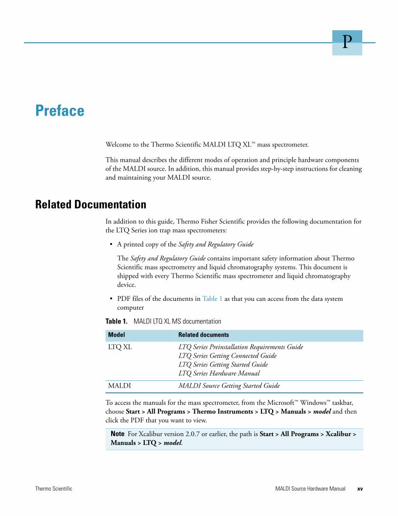
Related DocumentationIn addition to this guide, Thermo Fisher Scientific provides the following documentation for the LTQ Series ion trap mass spectrometers:
• A printed copy of the Safety and Regulatory Guide
The Safety and Regulatory Guide contains important safety information about Thermo Scientific mass spectrometry and liquid chromatography systems. This document is shipped with every Thermo Scientific mass spectrometer and liquid chromatography device.
• PDF files of the documents in Table 1 as that you can access from the data system computer
To access the manuals for the mass spectrometer, from the Microsoft™ Windows™ taskbar, choose Start > All Programs > Thermo Instruments > LTQ > Manuals > model and then click the PDF that you want to view.
Table 1. MALDI LTQ XL MS documentation
Model Related documents
LTQ XL LTQ Series Preinstallation Requirements GuideLTQ Series Getting Connected GuideLTQ Series Getting Started GuideLTQ Series Hardware Manual
MALDI MALDI Source Getting Started Guide
Note For Xcalibur version 2.0.7 or earlier, the path is Start > All Programs > Xcalibur > Manuals > LTQ > model.
Thermo Scientific MALDI Source Hardware Manual xv
Preface
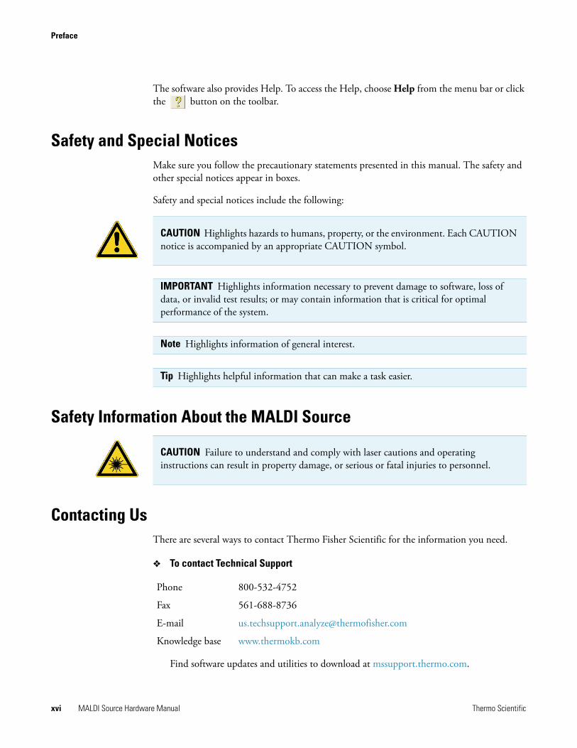
The software also provides Help. To access the Help, choose Help from the menu bar or click the button on the toolbar.
Safety and Special NoticesMake sure you follow the precautionary statements presented in this manual. The safety and other special notices appear in boxes.
Safety and special notices include the following:
Safety Information About the MALDI Source
Contacting UsThere are several ways to contact Thermo Fisher Scientific for the information you need.
To contact Technical Support
Find software updates and utilities to download at mssupport.thermo.com.
CAUTION Highlights hazards to humans, property, or the environment. Each CAUTION notice is accompanied by an appropriate CAUTION symbol.
IMPORTANT Highlights information necessary to prevent damage to software, loss of data, or invalid test results; or may contain information that is critical for optimal performance of the system.
Note Highlights information of general interest.
Tip Highlights helpful information that can make a task easier.
CAUTION Failure to understand and comply with laser cautions and operating instructions can result in property damage, or serious or fatal injuries to personnel.
Phone 800-532-4752
Fax 561-688-8736
E-mail [email protected]
Knowledge base www.thermokb.com
xvi MALDI Source Hardware Manual Thermo Scientific
Preface
To contact Customer Service for ordering information
To copy manuals from the Internet
Go to mssupport.thermo.com and click Customer Manuals in the left margin of the window.
To suggest changes to documentation or to Help
• Send an e-mail message to the Technical Publications Editor at [email protected].
• Complete a brief survey about this document by clicking the link below.Thank you in advance for your help.
Phone 800-532-4752
Fax 561-688-8731
E-mail [email protected]
Web site www.thermo.com/ms
Thermo Scientific MALDI Source Hardware Manual xvii

1
Introduction
This chapter describes the MALDI source, its basic components, and some of the advantages and disadvantages of matrix-assisted laser desorption ionization (MALDI) relative to electrospray ionization (ESI).
MALDI OverviewThe MALDI source is part of the Thermo Scientific family of mass spectrometer (MS) ion sources. The MALDI source is an optional source that is attached to the LTQ XL MS detector, in place of the Ion MAX™ API source.
In a typical MALDI analysis, you dissolve a sample in a solution containing a large excess of a matrix material with strong absorbency in the ultraviolet band. A few microliters of this solution are evaporated onto a sample plate that is then placed in an evacuated chamber. A UV laser vaporizes the sample crystals, carrying the analyte molecules into the vapor phase. Various charge transfer processes ionize the sample molecules, and an electrical potential draws the sample ions into the LTQ XL MS detector for analysis.
The MALDI modules are identified in Figure 1 and listed in Table 1.
Contents
• MALDI Overview
• MALDI Control Module
• MALDI Optics Module
• MALDI Sample Module
• How Do MALDI and ESI Compare?
Thermo Scientific MALDI Source Hardware Manual 1
1 IntroductionMALDI Overview
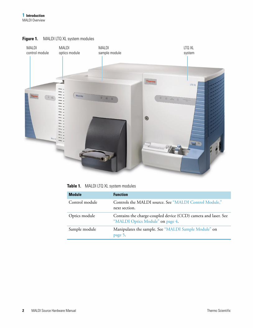
Figure 1. MALDI LTQ XL system modules
MALDIoptics module
MALDIsample module
MALDIcontrol module
LTQ XLsystem
Table 1. MALDI LTQ XL system modules
Module Function
Control module Controls the MALDI source. See “MALDI Control Module,” next section.
Optics module Contains the charge-coupled device (CCD) camera and laser. See “MALDI Optics Module” on page 4.
Sample module Manipulates the sample. See “MALDI Sample Module” on page 5.
2 MALDI Source Hardware Manual Thermo Scientific
1 IntroductionMALDI Control Module
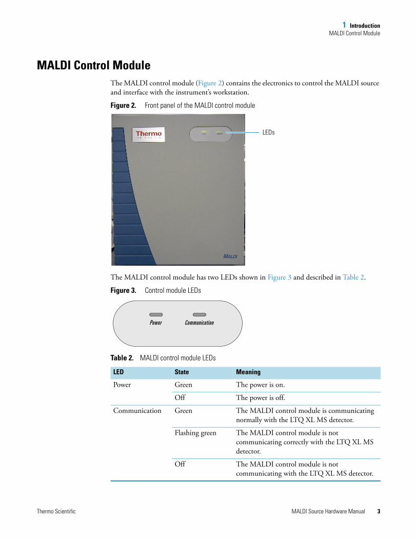
MALDI Control ModuleThe MALDI control module (Figure 2) contains the electronics to control the MALDI source and interface with the instrument’s workstation.
Figure 2. Front panel of the MALDI control module
The MALDI control module has two LEDs shown in Figure 3 and described in Table 2.
Figure 3. Control module LEDs
Table 2. MALDI control module LEDs
LED State Meaning
Power Green The power is on.
Off The power is off.
Communication Green The MALDI control module is communicating normally with the LTQ XL MS detector.
Flashing green The MALDI control module is not communicating correctly with the LTQ XL MS detector.
Off The MALDI control module is not communicating with the LTQ XL MS detector.
LEDs
Thermo Scientific MALDI Source Hardware Manual 3
1 IntroductionMALDI Optics Module
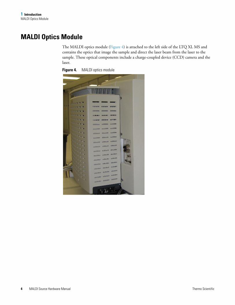
MALDI Optics ModuleThe MALDI optics module (Figure 4) is attached to the left side of the LTQ XL MS and contains the optics that image the sample and direct the laser beam from the laser to the sample. These optical components include a charge-coupled device (CCD) camera and the laser.
Figure 4. MALDI optics module
4 MALDI Source Hardware Manual Thermo Scientific
1 IntroductionMALDI Sample Module
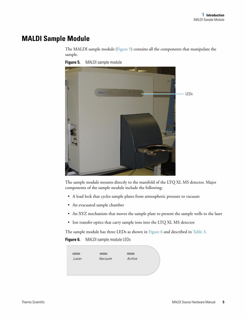
MALDI Sample Module The MALDI sample module (Figure 5) contains all the components that manipulate the sample.
Figure 5. MALDI sample module
The sample module mounts directly to the manifold of the LTQ XL MS detector. Major components of the sample module include the following:
• A load lock that cycles sample plates from atmospheric pressure to vacuum
• An evacuated sample chamber
• An XYZ mechanism that moves the sample plate to present the sample wells to the laser
• Ion transfer optics that carry sample ions into the LTQ XL MS detector
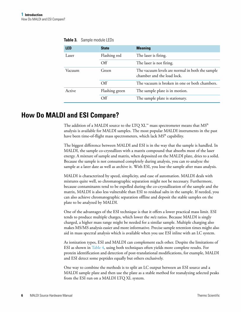
The sample module has three LEDs as shown in Figure 6 and described in Table 3.
Figure 6. MALDI sample module LEDs
LEDs
VacuumLaser Active
Thermo Scientific MALDI Source Hardware Manual 5
1 IntroductionHow Do MALDI and ESI Compare?
How Do MALDI and ESI Compare?The addition of a MALDI source to the LTQ XL™ mass spectrometer means that MSn analysis is available for MALDI samples. The most popular MALDI instruments in the past have been time-of-flight mass spectrometers, which lack MSn capability.
The biggest difference between MALDI and ESI is in the way that the sample is handled. In MALDI, the sample co-crystallizes with a matrix compound that absorbs most of the laser energy. A mixture of sample and matrix, when deposited on the MALDI plate, dries to a solid. Because the sample is not consumed completely during analysis, you can re-analyze the sample at a later date as well as archive it. With ESI, you lose the sample after mass analysis.
MALDI is characterized by speed, simplicity, and ease of automation. MALDI deals with mixtures quite well, so chromatographic separation might not be necessary. Furthermore, because contaminants tend to be expelled during the co-crystallization of the sample and the matrix, MALDI is also less vulnerable than ESI to residual salts in the sample. If needed, you can also achieve chromatographic separation offline and deposit the stable samples on the plate to be analyzed by MALDI.
One of the advantages of the ESI technique is that it offers a lower practical mass limit. ESI tends to produce multiple charges, which lower the m/z ratios. Because MALDI is singly charged, a higher mass range might be needed for a similar sample. Multiple charging also makes MS/MS analysis easier and more informative. Precise sample retention times might also aid in mass spectral analysis which is available when you use ESI inline with an LC system.
As ionization types, ESI and MALDI can complement each other. Despite the limitations of ESI as shown in Table 4, using both techniques often yields more complete results. For protein identification and detection of post-translational modifications, for example, MALDI and ESI detect some peptides equally but others exclusively.
One way to combine the methods is to split an LC output between an ESI source and a MALDI sample plate and then use the plate as a stable method for reanalyzing selected peaks from the ESI run on a MALDI LTQ XL system.
Table 3. Sample module LEDs
LED State Meaning
Laser Flashing red The laser is firing.
Off The laser is not firing.
Vacuum Green The vacuum levels are normal in both the sample chamber and the load lock.
Off The vacuum is broken in one or both chambers.
Active Flashing green The sample plate is in motion.
Off The sample plate is stationary.
6 MALDI Source Hardware Manual Thermo Scientific
1 IntroductionHow Do MALDI and ESI Compare?
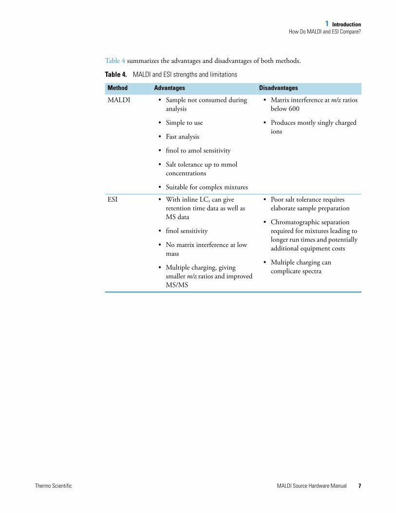
Table 4 summarizes the advantages and disadvantages of both methods.
Table 4. MALDI and ESI strengths and limitations
Method Advantages Disadvantages
MALDI • Sample not consumed during analysis
• Simple to use
• Fast analysis
• fmol to amol sensitivity
• Salt tolerance up to mmol concentrations
• Suitable for complex mixtures
• Matrix interference at m/z ratios below 600
• Produces mostly singly charged ions
ESI • With inline LC, can give retention time data as well as MS data
• fmol sensitivity
• No matrix interference at low mass
• Multiple charging, giving smaller m/z ratios and improved MS/MS
• Poor salt tolerance requires elaborate sample preparation
• Chromatographic separation required for mixtures leading to longer run times and potentially additional equipment costs
• Multiple charging can complicate spectra
Thermo Scientific MALDI Source Hardware Manual 7

2
Functional Description
This chapter describes the MALDI source assembly components and the software that handles the tasks associated with sample plates and data acquisition.
Sample ModuleThe MALDI sample module is a part of the ion source that has the following internal components:
• “Load Lock and Sample Chamber,” next section
• “Ion Transfer Optics” on page 10
• “Vacuum System” on page 10
Load Lock and Sample Chamber
The load lock and the sample chamber are parts of the sample module. In the sample chamber, the sample plate mounts on a platform that moves in two dimensions to position each sample well for the laser. This platform is part of the XYZ mechanism. Spring tension clamps hold the sample plate onto the XYZ mechanism.
The movement of the XYZ mechanism is guided by two precision vacuum-rated stepper motors, each of which drives a stainless steel linear actuator. The movement of the stage is bounded by optical interrupt limit switches at the beginning and end of each actuator’s range of motion.
Contents
• Sample Module
• Optics Module
• Sample and Data Automation
• MALDI Source Status Information
• Sample Plates
Thermo Scientific MALDI Source Hardware Manual 9
2 Functional DescriptionSample Module
You control the movement of the XYZ mechanism through the MALDI software. The software uses a pixel map to provide point- and click-on positioning for the sample plate based on the image from the camera.
Ion Transfer Optics
The MALDI source contains a quadrupole ion guide and a DC extraction field that channel ions from the sample plate into the ion optics of the LTQ XL MS detector. This quadrupole and DC extraction field assembly (Q00) provides no mass selection—it is only a field to regulate ions in the detector.
Vacuum System
The MALDI source uses the pumps that are specific to the LTQ XL MS detector to pump down the load lock and the sample chamber. A turbomolecular pump with a Holweck stage, backed up by an oil-sealed rotary vane rough pump, evacuates the LTQ XL ion path and, by extension, the MALDI sample chamber that is contiguous with it. A second rotary vane pump evacuates the load lock. Vacuum pressure sensors measure the vacuum level in both chambers, and the sensors feed data back to the LTQ XL vacuum controls.
When you place a sample plate on the load lock and you click the Insert Plate button to load the sample plate, the sample plate moves into the load lock chamber, the door closes, and the vacuum system engages automatically to pump down the load lock. When the load lock chamber pressure is less than 120 mTorr, the sample plate moves from the load lock chamber to the sample chamber. (For information about loading a plate, see “Loading Sample Plates” on page 17.)
When you click the Eject Sample Plate button, a vent valve automatically restores the load lock chamber to atmospheric pressure within about 40 seconds.
Note If the XYZ mechanism in your MALDI source is defective, contact Thermo Fisher Scientific Technical Support or a field service engineer.
Note If the ion transfer optics assembly in the MALDI source is defective, contact Thermo Scientific Technical Support or a field service engineer.
CAUTION Failure to understand and comply with laser cautions and operating instructions can result in property damage, or serious or fatal injuries to personnel.
10 MALDI Source Hardware Manual Thermo Scientific
2 Functional DescriptionOptics Module
Optics ModuleThe optics module contains the following components:
• “Camera,” next section
• “Laser” on page 11
Camera
The MALDI source uses a charge-coupled device (CCD) camera to image the target crystals. The camera uses the same optical axis as the laser beam, picking up the image of the sample plate from the dichroic mirror that guides the laser.
Light for the camera is provided by a fiber optic strand that carries light from an LED through the ion transfer quadrupole and into the sample chamber. For more information about the camera and the optical illuminator, see Figure 4 on page 4.
The MALDI software uses optical recognition routines on the camera image to identify the type of sample plate (see “Sample Plates” on page 15) and to identify the sample plate calibration targets on the corners of each plate. These calibration targets orient the sample plate and create a digital map of the plate for navigation.
Laser
The MALDI source uses a nitrogen gas laser (337.7 nm) with a frequency of 60 Hz. The laser is housed in the MALDI optics module (see Figure 4 on page 4).
For additional about the laser, see the following:
• “Laser Energy Path,” next section
• “Laser Performance” on page 13
Thermo Scientific MALDI Source Hardware Manual 11
2 Functional DescriptionOptics Module
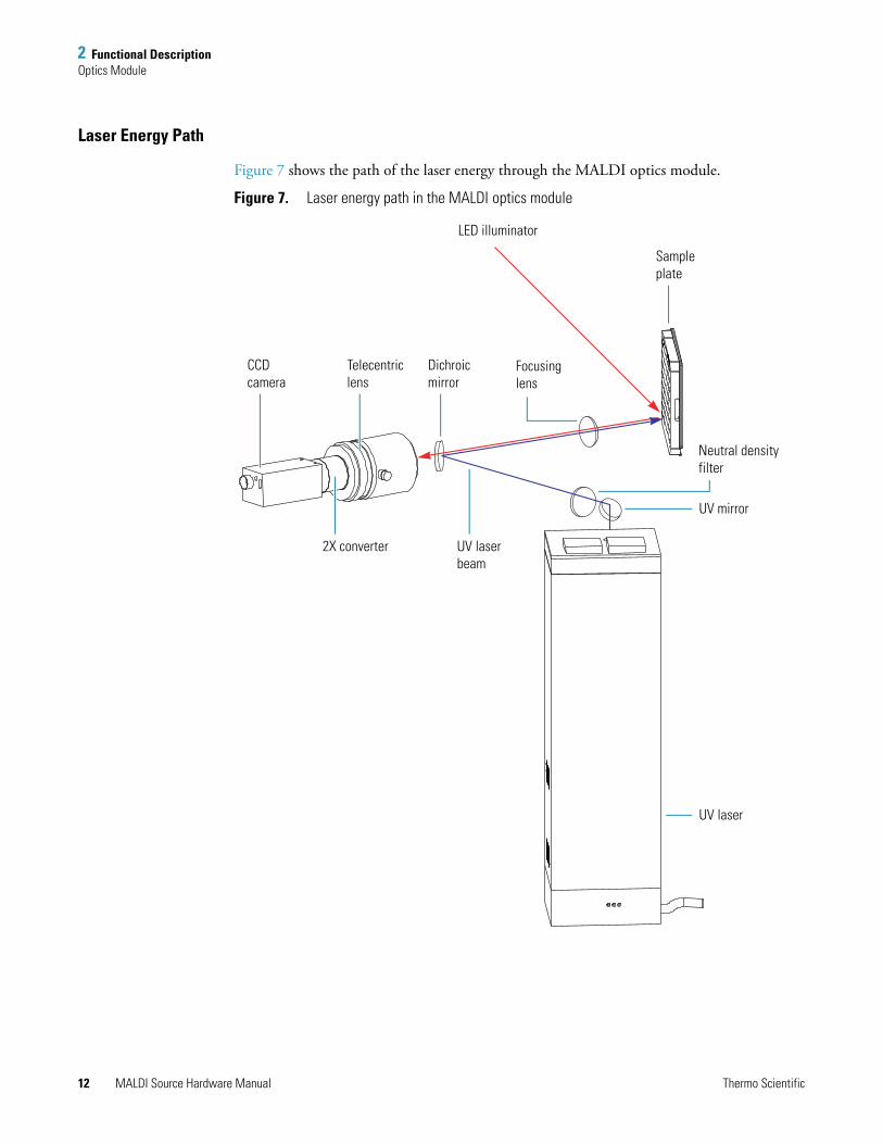
Laser Energy Path
Figure 7 shows the path of the laser energy through the MALDI optics module.
Figure 7. Laser energy path in the MALDI optics module
Dichroicmirror
CCDcamera
LED illuminator
Sampleplate
UV laserbeam
Focusinglens
Telecentriclens
2X converter
Neutral density filter
UV mirror
UV laser
12 MALDI Source Hardware Manual Thermo Scientific
2 Functional DescriptionSample and Data Automation
Laser Performance
In addition to alignment, the other factor that influences the laser energy delivered to the sample is the output power of the laser itself.
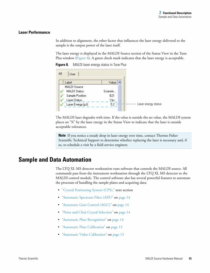
The laser energy is displayed in the MALDI Source section of the Status View in the Tune Plus window (Figure 8). A green check mark indicates that the laser energy is acceptable.
Figure 8. MALDI laser energy status in Tune Plus
The MALDI laser degrades with time. If the value is outside the set value, the MALDI system places an “X” by the laser energy in the Status View to indicate that the laser is outside acceptable tolerances.
Sample and Data AutomationThe LTQ XL MS detector workstation runs software that controls the MALDI source. All commands pass from the instrument workstation through the LTQ XL MS detector to the MALDI control module. The control software also has several powerful features to automate the processes of handling the sample plates and acquiring data:
• “Crystal Positioning System (CPS),” next section
• “Automatic Spectrum Filter (ASF)” on page 14
• “Automatic Gain Control (AGC)” on page 14
• “Point and Click Crystal Selection” on page 14
• “Automatic Plate Recognition” on page 14
• “Automatic Plate Calibration” on page 15
• “Automatic Video Calibration” on page 15
Note If you notice a steady drop in laser energy over time, contact Thermo Fisher Scientific Technical Support to determine whether replacing the laser is necessary and, if so, to schedule a visit by a field service engineer.
Laser energy status
Thermo Scientific MALDI Source Hardware Manual 13
2 Functional DescriptionSample and Data Automation
Crystal Positioning System (CPS)
The MALDI control software processes the image gathered by the camera into a pixel map and automatically identifies matrix crystals on the image. In MALDI you can select the pattern that you want to use when the laser is fired. The MALDI Crystal Positioning System (CPS) automatically recognizes and navigates from crystal to crystal.
Automatic Spectrum Filter (ASF)
You can instruct MALDI control software to recognize acceptable spectra, defined as having a total ion current above a set threshold value over a designated mass range. By setting the mass range to exclude most of the matrix background and choosing a suitable threshold level, you can cause the system to recognize useful crystals and continue collecting spectral data from those crystals. Likewise, the system disregards junk data and continues on when a selected crystal proves to have little or no sample.
ASF increases the speed of analyses and reduces wasted data. It also improves the signal-to-noise ratio of the final spectrum by filtering out bad data before performing spectrum averaging.
Automatic Gain Control (AGC)
With the AGC feature, the MALDI control software can determine the number of laser shots on a given crystal based on the signal strength measured in a given mass range: a low signal results in more data acquisition shots, while a high signal allows fewer shots.
Point and Click Crystal Selection
When you set the Plate Motion to Manual in the MALDI control software, you can use the mouse to select the desired crystal in the camera image.
Automatic Plate Recognition
The MALDI control software uses patterns etched in the surface of the sample plate to identify the plate (see “Sample Plates” on page 15). The software then automatically uses this information to map the plate for navigation.
Note If the plate is moving but no spectrum is shown within 30 seconds, then you might have set the threshold too high.
14 MALDI Source Hardware Manual Thermo Scientific
2 Functional DescriptionMALDI Source Status Information
Automatic Plate Calibration
Accurate positioning of the sample plate is critical to MALDI. The laser and camera must be accurately aligned to allow for precise crystal selection. The sample well must be directly centered on the ion transfer quadrupole for efficient collection of the sample ions into the MALDI LTQ XL MS detector.
Each sample plate is marked with four crosses, one at each corner, and three of which are used to map and position the sample plate. The can then find and identify these crosses.
Automatic Video Calibration
The MALDI control software automatically calibrates the video display, both to center the image and to measure the distance represented by each pixel in the pixel map. Using this information, combined with the sample plate calibration, the MALDI sample module moves the sample plate accurately to present any point to the camera and laser.
MALDI Source Status InformationTune Plus for the MALDI source includes information about the MALDI source in addition to standard information for the LTQ XL (see Figure 8 on page 13). This information includes the following:
• The current state of the MALDI source: scanning, in Standby mode, or off
• The location of the sample well that is being scanned
• The status of the laser: Yes (on), in Standby mode, or off
• The current laser energy rating
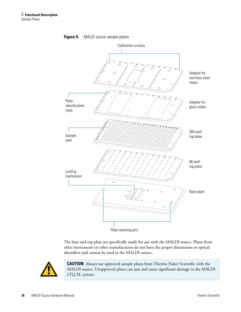
Sample PlatesThe sample plates used in the MALDI source (Figure 9) are a two-piece construction: a base and a stainless steel top plate that contains the samples. Four types of top plates are available:
• 96-well plate
• 384-well plate
• Adapter for four stainless steel slides (for tissue imaging)
• Adapter for two glass slides (for tissue imaging)
The MALDI control software automatically identifies which sample plate is being used, and the sample plate type diagnostics provide information about the plate. For more information, see “Sample Plate Type Determination” on page 47.
Thermo Scientific MALDI Source Hardware Manual 15
2 Functional DescriptionSample Plates
Figure 9. MALDI source sample plates
The base and top plate are specifically made for use with the MALDI source. Plates from other instruments or other manufacturers do not have the proper dimensions or optical identifiers and cannot be used in the MALDI source.
Adapter forstainless steel slides
Adapter forglass slides
384-welltop plate
96-welltop plate
Base plate
Plate identification mark
Samplewell
Lockingmechanism
Plate retaining pins
Calibration crosses
CAUTION Always use approved sample plates from Thermo Fisher Scientific with the MALDI source. Unapproved plates can jam and cause significant damage to the MALDI LTQ XL system.
16 MALDI Source Hardware Manual Thermo Scientific
2 Functional DescriptionSample Plates
The stainless steel sample plate has a polished mirror finish to minimize roughness and potential cross-contamination. Always clean the sample plate carefully, as described in the MALDI Source Getting Started Guide.
Loading Sample Plates
You load the sample plate by sliding the plate into the loading slot where clamps lock the sample plate to the pickup stage. The pickup stage accepts the plate in only one orientation. A sensor in the load lock interface verifies that there is a sample plate on the pickup stage. The pickup stage then retracts with the plate, rotates it to the vertical position, and seals the load lock chamber.
The load lock is cycled from atmospheric pressure to main chamber vacuum pressure by means of the rough vacuum pump. When the pressure in the load lock reaches 120 mTorr, the pickup stage transfers the sample plate through the automated gate valve between the load lock and the sample chamber. The plate is then handed off to the XYZ mechanism (see “Load Lock and Sample Chamber” on page 9). Optical interrupt limit sensors at the top and bottom of the load lock define the upper and lower limits of the pickup stage’s movement.
CAUTION Improper cleaning of the sample plate can potentially etch and leave contaminants on the surface or scratches on the plate. Scratches reduce the useful life of the plate and can harbor impurities.
Thermo Scientific MALDI Source Hardware Manual 17

3
Daily Operation
For optimal MALDI operation, perform the procedures in this chapter each day before and after operating the source. Use these daily operations to help you detect, fix, and prevent problems that can reduce the sensitivity of the LTQ XL MS detector.
For regular maintenance procedures, see “Maintenance” on page 27.
Operational GuidelinesTo run the mass spectrometer in the MALDI mode, read through these operational guidelines before you set the MALDI parameters and the mass spectrometer parameters to acquire data:
• “Controlling the Motion of the Target Plate,” next section
• “Adding Microscans” on page 20
• “Handling Sample Plates” on page 20
Controlling the Motion of the Target Plate
As described in the previous chapter, you can control the motion of the target plate either automatically (for example, spiral motion) or manually. In order to decide which mode to use, consider that the rate of sample degradation depends on the matrix, the sample preparation technique, and the laser energy. You can manually shift the target plate to another position within the same spot, but this requires constant monitoring of the signal level.
Contents
• Operational Guidelines
• Turning the MALDI LTQ XL System Off or On
• Preparing the MALDI Source for Use
Thermo Scientific MALDI Source Hardware Manual 19
3 Daily OperationOperational Guidelines
Adding Microscans
The number of microscans depends on the type of experiment that you are performing. If you are working with relatively concentrated samples (15 to 100 fmol of sample per sample spot), 1 to 3 microscans are usually sufficient. For 10 fmol or less, up to 5 microscans might be needed, and if you are working with 1 fmol or less, then you might need 10 microscans or more. A scan with a higher number of microscans provides more signal averaging but takes longer to acquire.
If your analyte concentration is too low, you might need to increase the number of scans averaged to get a good signal-to-noise ratio in your data.
Handling Sample Plates
Observe the following guidelines when handling the sample plate:
• Avoid scratching or denting the plate in any way. Even very small scratches can harbor contaminants.
• Always handle the sample plate with lint-free, powder-free gloves.
• Never touch the top surface of the plate, even with gloves.
• Use only high-purity solvents: HPLC-grade or better.
• Avoid the use of anything abrasive on the plate, including abrasive cleaners.
• Avoid caustic materials such as strong acids or bases, as they can etch the surface of the plate.
• Avoid exposing the plate to high heat. (Gentle warming to dry the plate is acceptable.)
• Store the plate in a desiccator or under vacuum when not in use.
• Protect the plate from dust.
• If a plate has been stored for an extended period, follow the cleaning procedure described in the MALDI Source Getting Started Guide immediately before using the plate, even if the plate was cleaned before being stored.
20 MALDI Source Hardware Manual Thermo Scientific
3 Daily OperationTurning the MALDI LTQ XL System Off or On
Turning the MALDI LTQ XL System Off or OnAfter you have completed your work for the day, place the MALDI LTQ XL system into Standby mode, which turns the MALDI source off. Do the reverse to resume your work.
To put the MALDI LTQ XL system into Standby mode
1. On the Windows taskbar, choose Start > All Programs > Xcalibur > LTQTune.
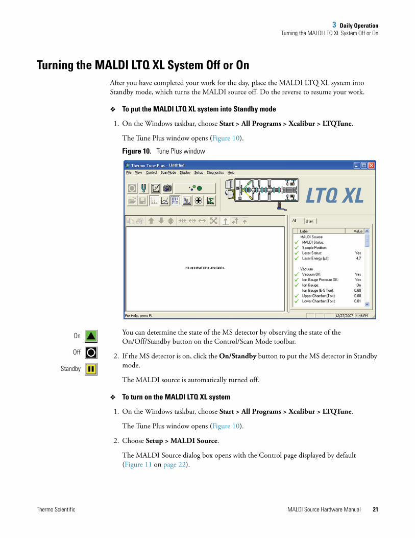
The Tune Plus window opens (Figure 10).
Figure 10. Tune Plus window
You can determine the state of the MS detector by observing the state of the On/Off/Standby button on the Control/Scan Mode toolbar.
2. If the MS detector is on, click the On/Standby button to put the MS detector in Standby mode.
The MALDI source is automatically turned off.
To turn on the MALDI LTQ XL system
1. On the Windows taskbar, choose Start > All Programs > Xcalibur > LTQTune.
The Tune Plus window opens (Figure 10).
2. Choose Setup > MALDI Source.
The MALDI Source dialog box opens with the Control page displayed by default (Figure 11 on page 22).
Standby
Off
On
Thermo Scientific MALDI Source Hardware Manual 21
3 Daily OperationTurning the MALDI LTQ XL System Off or On
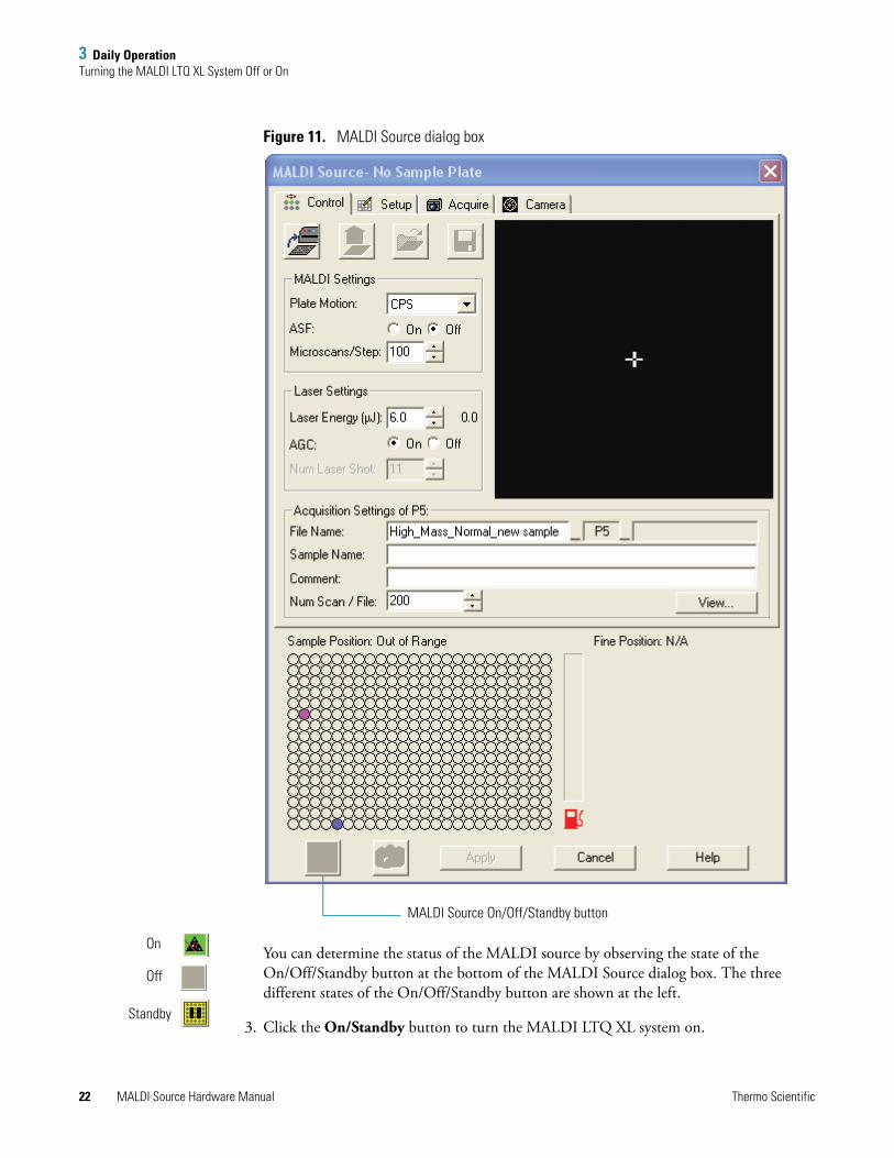
Figure 11. MALDI Source dialog box
You can determine the status of the MALDI source by observing the state of the On/Off/Standby button at the bottom of the MALDI Source dialog box. The three different states of the On/Off/Standby button are shown at the left.
3. Click the On/Standby button to turn the MALDI LTQ XL system on.
MALDI Source On/Off/Standby button
On
Standby
Off
22 MALDI Source Hardware Manual Thermo Scientific
3 Daily OperationPreparing the MALDI Source for Use
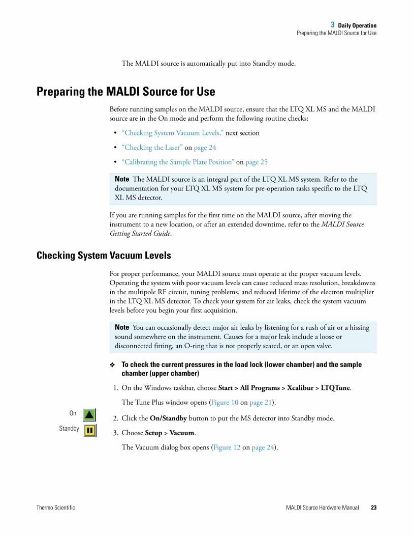
The MALDI source is automatically put into Standby mode.
Preparing the MALDI Source for UseBefore running samples on the MALDI source, ensure that the LTQ XL MS and the MALDI source are in the On mode and perform the following routine checks:
• “Checking System Vacuum Levels,” next section
• “Checking the Laser” on page 24
• “Calibrating the Sample Plate Position” on page 25
If you are running samples for the first time on the MALDI source, after moving the instrument to a new location, or after an extended downtime, refer to the MALDI Source Getting Started Guide.
Checking System Vacuum Levels
For proper performance, your MALDI source must operate at the proper vacuum levels. Operating the system with poor vacuum levels can cause reduced mass resolution, breakdowns in the multipole RF circuit, tuning problems, and reduced lifetime of the electron multiplier in the LTQ XL MS detector. To check your system for air leaks, check the system vacuum levels before you begin your first acquisition.
To check the current pressures in the load lock (lower chamber) and the sample chamber (upper chamber)
1. On the Windows taskbar, choose Start > All Programs > Xcalibur > LTQTune.
The Tune Plus window opens (Figure 10 on page 21).
2. Click the On/Standby button to put the MS detector into Standby mode.
3. Choose Setup > Vacuum.
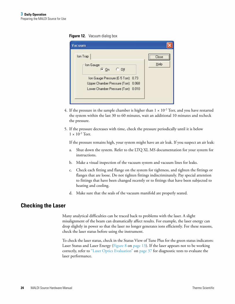
The Vacuum dialog box opens (Figure 12 on page 24).
Note The MALDI source is an integral part of the LTQ XL MS system. Refer to the documentation for your LTQ XL MS system for pre-operation tasks specific to the LTQ XL MS detector.
Note You can occasionally detect major air leaks by listening for a rush of air or a hissing sound somewhere on the instrument. Causes for a major leak include a loose or disconnected fitting, an O-ring that is not properly seated, or an open valve.
On
Standby
Thermo Scientific MALDI Source Hardware Manual 23
3 Daily OperationPreparing the MALDI Source for Use
Figure 12. Vacuum dialog box
4. If the pressure in the sample chamber is higher than 1 × 10⁻² Torr, and you have restarted the system within the last 30 to 60 minutes, wait an additional 10 minutes and recheck the pressure.
5. If the pressure decreases with time, check the pressure periodically until it is below 1 × 10⁻² Torr.
If the pressure remains high, your system might have an air leak. If you suspect an air leak:
a. Shut down the system. Refer to the LTQ XL MS documentation for your system for instructions.
b. Make a visual inspection of the vacuum system and vacuum lines for leaks.
c. Check each fitting and flange on the system for tightness, and tighten the fittings or flanges that are loose. Do not tighten fittings indiscriminately. Pay special attention to fittings that have been changed recently or to fittings that have been subjected to heating and cooling.
d. Make sure that the seals of the vacuum manifold are properly seated.
Checking the Laser
Many analytical difficulties can be traced back to problems with the laser. A slight misalignment of the beam can dramatically affect results. For example, the laser energy can drop slightly in power so that the laser no longer generates ions efficiently. For these reasons, check the laser status before using the instrument.
To check the laser status, check in the Status View of Tune Plus for the green status indicators: Laser Status and Laser Energy (Figure 8 on page 13). If the laser appears not to be working correctly, refer to “Laser Optics Evaluation” on page 37 for diagnostic tests to evaluate the laser performance.
24 MALDI Source Hardware Manual Thermo Scientific

3 Daily OperationPreparing the MALDI Source for Use
Calibrating the Sample Plate Position
The MALDI source automatically calibrates the sample plate each time a plate is inserted into the source. If an automatic plate calibration fails, see “Sample Plate Calibration Fails” on page 71.
Thermo Scientific MALDI Source Hardware Manual 25

4
Maintenance
Perform these basic maintenance tasks to help keep your MALDI source working properly.
Checking the Laser PositionIn order to guide the laser accurately to an analyte crystal, center the laser beam on the optical axis of the camera and on the hole in the ion transfer quadrupole.
To align the laser with the optical axis of the camera
1. Prepare a sample plate according to your standard procedure. Apply a thin, homogenous, matrix-only layer to sample well A1 (and other wells as needed).
2. Slide the sample plate into the loading slot.
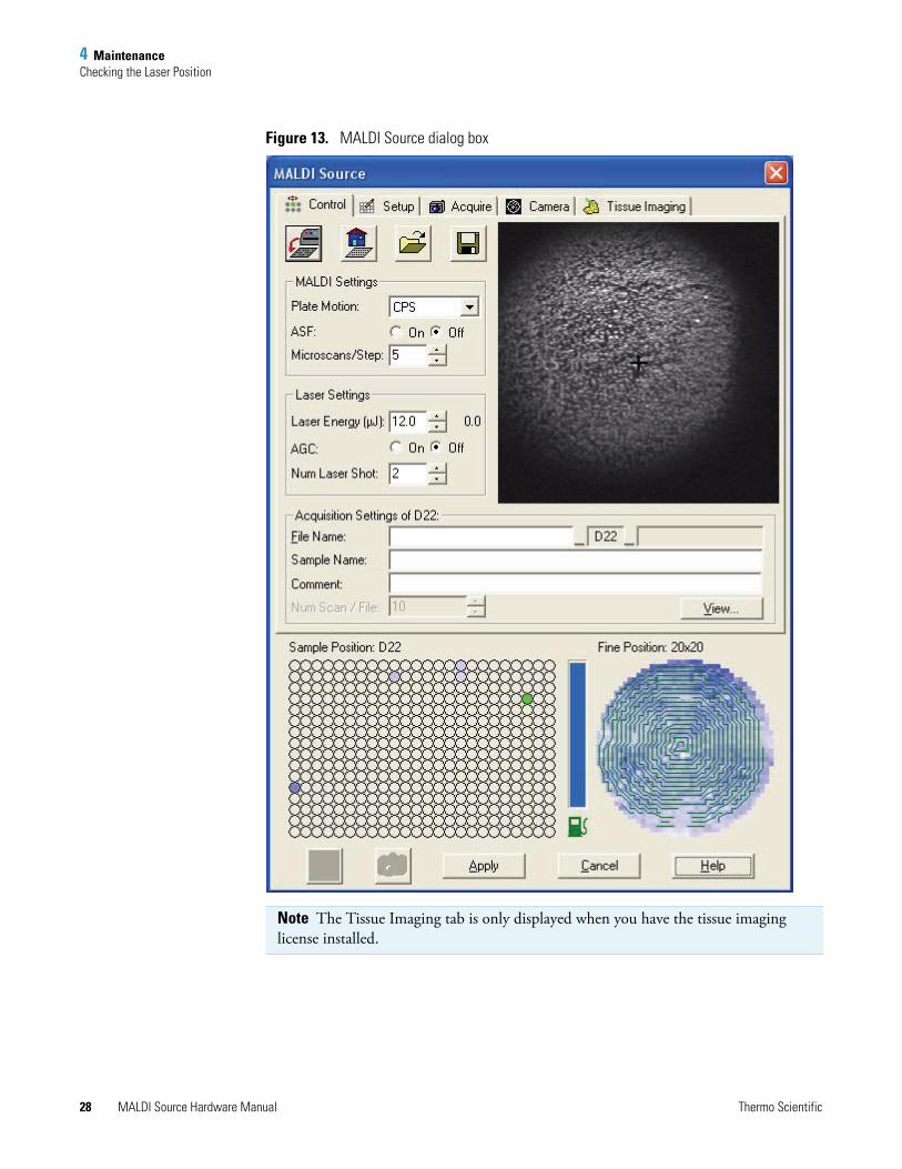
3. In the Tune Plus window, choose Setup > MALDI Source.
The MALDI Source dialog box opens with the Control page displayed by default (Figure 13 on page 28).
Contents
• Checking the Laser Position
• Replacing the Solenoid Vacuum Valve
Thermo Scientific MALDI Source Hardware Manual 27
4 MaintenanceChecking the Laser Position
Figure 13. MALDI Source dialog box
Note The Tissue Imaging tab is only displayed when you have the tissue imaging license installed.
28 MALDI Source Hardware Manual Thermo Scientific
4 MaintenanceChecking the Laser Position
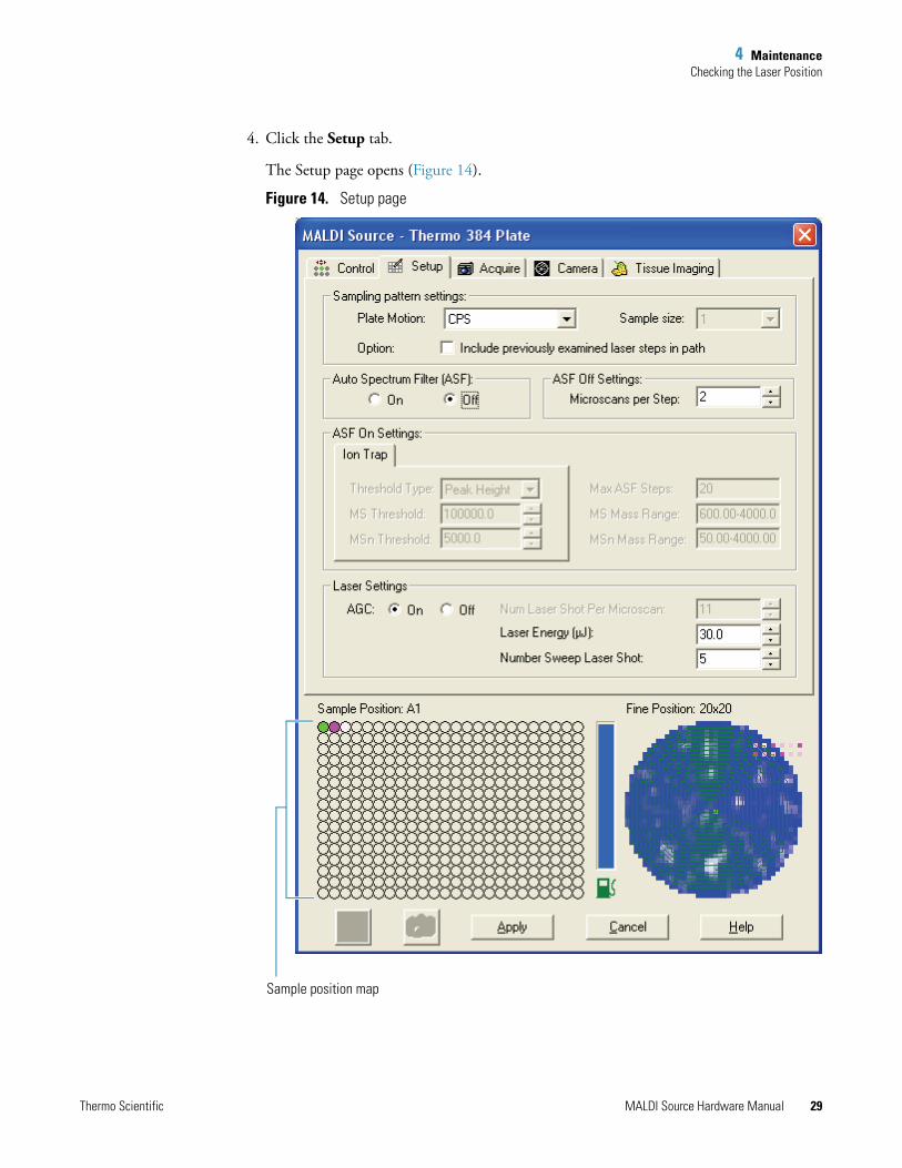
4. Click the Setup tab.
The Setup page opens (Figure 14).
Figure 14. Setup page
Sample position map
Thermo Scientific MALDI Source Hardware Manual 29
4 MaintenanceChecking the Laser Position
5. In the Sample Position Map (Figure 14 on page 29), point and click to position the sample well with the thin layer of matrix in the center of the camera display.
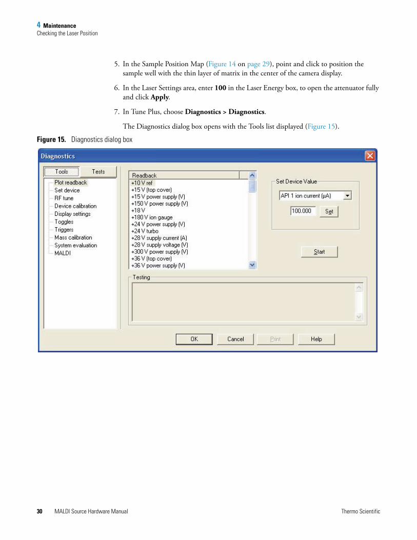
6. In the Laser Settings area, enter 100 in the Laser Energy box, to open the attenuator fully and click Apply.
7. In Tune Plus, choose Diagnostics > Diagnostics.
The Diagnostics dialog box opens with the Tools list displayed (Figure 15).
Figure 15. Diagnostics dialog box
30 MALDI Source Hardware Manual Thermo Scientific
4 MaintenanceChecking the Laser Position
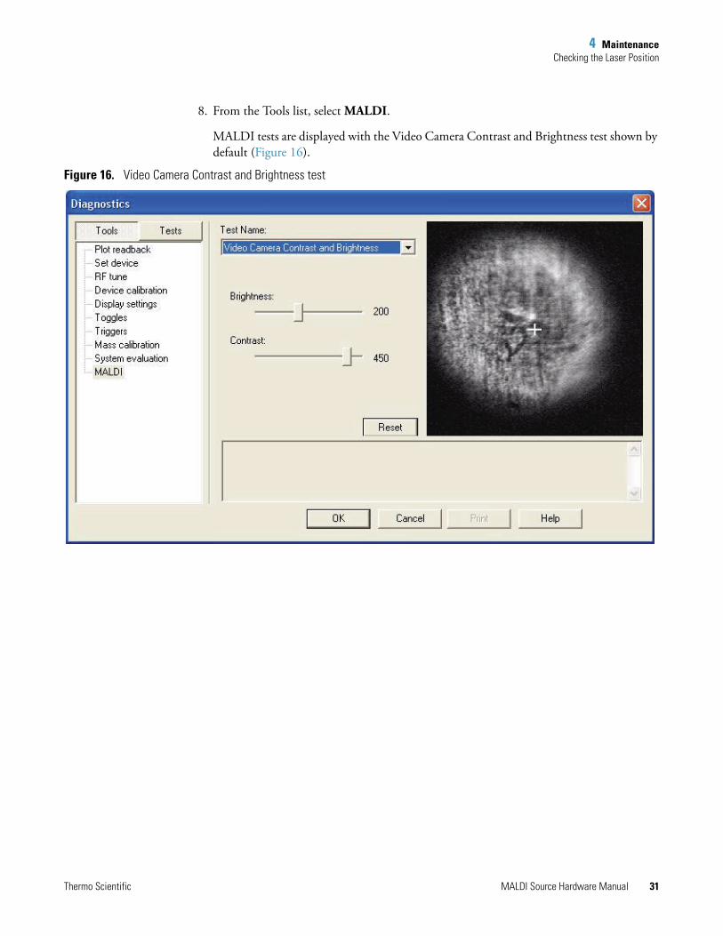
8. From the Tools list, select MALDI.
MALDI tests are displayed with the Video Camera Contrast and Brightness test shown by default (Figure 16).
Figure 16. Video Camera Contrast and Brightness test
Thermo Scientific MALDI Source Hardware Manual 31
4 MaintenanceChecking the Laser Position
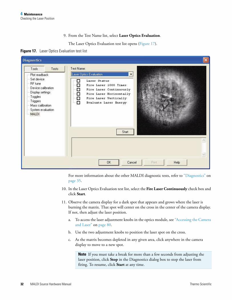
9. From the Test Name list, select Laser Optics Evaluation.
The Laser Optics Evaluation test list opens (Figure 17).
Figure 17. Laser Optics Evaluation test list
For more information about the other MALDI diagnostic tests, refer to “Diagnostics” on page 35.
10. In the Laser Optics Evaluation test list, select the Fire Laser Continuously check box and click Start.
11. Observe the camera display for a dark spot that appears and grows where the laser is burning the matrix. That spot will center on the cross in the center of the camera display. If not, then adjust the laser position.
a. To access the laser adjustment knobs in the optics module, see “Accessing the Camera and Laser” on page 80.
b. Use the two adjustment knobs to position the laser spot on the cross.
c. As the matrix becomes depleted in any given area, click anywhere in the camera display to move to a new spot.
Note If you must take a break for more than a few seconds from adjusting the laser position, click Stop in the Diagnostics dialog box to stop the laser from firing. To resume, click Start at any time.
32 MALDI Source Hardware Manual Thermo Scientific
4 MaintenanceReplacing the Solenoid Vacuum Valve
12. When the laser is centered in the camera display, click Stop, and close the Diagnostics dialog box.
13. Remove the sample plate and store it in a dark, dry location.
14. Reinstall the optics module cover and the LTQ XL top cover.
Replacing the Solenoid Vacuum ValveThe mechanical pump that is connected to the MALDI sample module and the NW25 solenoid vacuum valve controls the evacuation and venting of the load lock chamber.
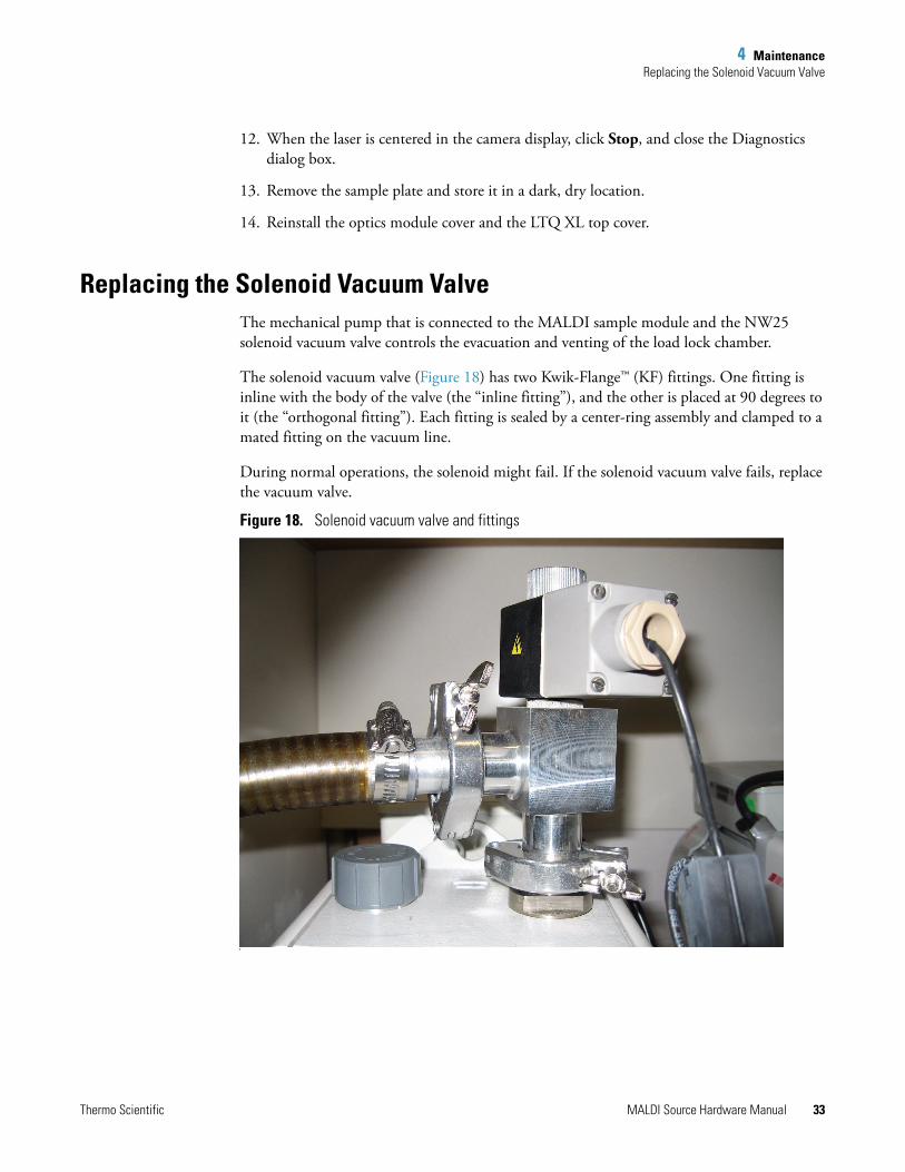
The solenoid vacuum valve (Figure 18) has two Kwik-Flange™ (KF) fittings. One fitting is inline with the body of the valve (the “inline fitting”), and the other is placed at 90 degrees to it (the “orthogonal fitting”). Each fitting is sealed by a center-ring assembly and clamped to a mated fitting on the vacuum line.
During normal operations, the solenoid might fail. If the solenoid vacuum valve fails, replace the vacuum valve.
Figure 18. Solenoid vacuum valve and fittings
I
Replace with drawing and callouts
Thermo Scientific MALDI Source Hardware Manual 33
4 MaintenanceReplacing the Solenoid Vacuum Valve
To replace the vacuum valve
1. With the load lock chamber at atmospheric pressure, unplug the vacuum valve cable from the port labeled Vacuum Valve on the back of the MALDI control module.
2. Remove the hinged clamps from the KF fittings on the vacuum valve.
3. Inspect the O-ring portion of the centering ring to ensure that it is free of any cuts, nicks, or imperfections that might cause it to leak. If it is defective, replace the centering ring.
4. Use the hinged clamps to secure the KF fittings on the vacuum valve.
• Clamp the solenoid vacuum valve to the pump inlet fitting.
• Clamp the vacuum line from the load lock chamber to the orthogonal fitting of the solenoid vacuum valve.
5. Connect the solenoid cable from the replacement valve to the port labeled Vacuum Valve on the back of the MALDI control module.
34 MALDI Source Hardware Manual Thermo Scientific
5
Diagnostics
Use the following MALDI diagnostics to diagnose, evaluate, tune, and calibrate the MALDI LTQ XL system.
Diagnostic System OverviewThe diagnostic system is available through the Diagnostics menu in Tune Plus.
To diagnose and resolve instrument problems using Tune Plus
1. In Tune Plus, choose Diagnostics > Diagnostics.
The Diagnostics dialog box opens with the Tools list displayed by default (Figure 15 on page 30).
2. From the Tools list, select MALDI.
MALDI tests are displayed with the Video Camera Contrast and Brightness test shown by default (Figure 17 on page 32.)
Figure 19 shows the expanded MALDI test list.
Contents
• Diagnostic System Overview
• Laser Optics Evaluation
• MALDI System Evaluation
• Working With Sample Plates
• Vacuum and Valves Evaluation
• Tuning the Video Camera
• Preparing a Thin-Layer Matrix Sample
• Running a Full Video Calibration
Thermo Scientific MALDI Source Hardware Manual 35
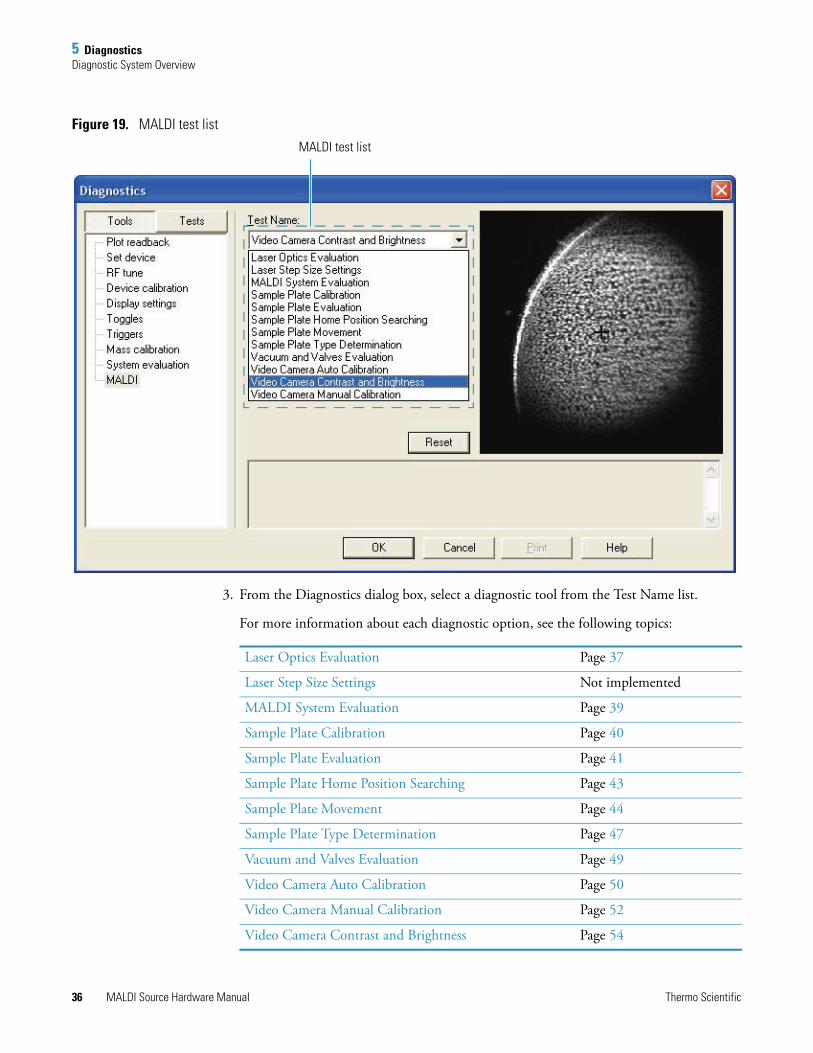
5 DiagnosticsDiagnostic System Overview
Figure 19. MALDI test list
3. From the Diagnostics dialog box, select a diagnostic tool from the Test Name list.
For more information about each diagnostic option, see the following topics:
MALDI test list
Laser Optics Evaluation Page 37
Laser Step Size Settings Not implemented
MALDI System Evaluation Page 39
Sample Plate Calibration Page 40
Sample Plate Evaluation Page 41
Sample Plate Home Position Searching Page 43
Sample Plate Movement Page 44
Sample Plate Type Determination Page 47
Vacuum and Valves Evaluation Page 49
Video Camera Auto Calibration Page 50
Video Camera Manual Calibration Page 52
Video Camera Contrast and Brightness Page 54
36 MALDI Source Hardware Manual Thermo Scientific
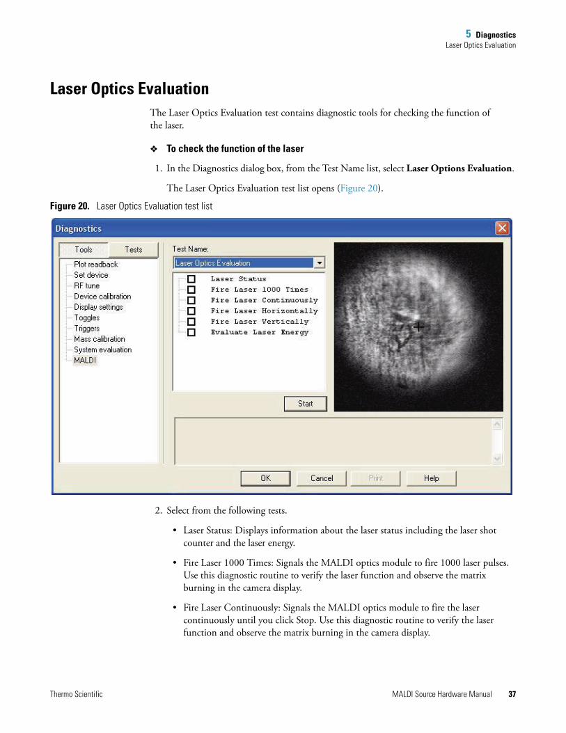
5 DiagnosticsLaser Optics Evaluation
Laser Optics EvaluationThe Laser Optics Evaluation test contains diagnostic tools for checking the function of the laser.
To check the function of the laser
1. In the Diagnostics dialog box, from the Test Name list, select Laser Options Evaluation.
The Laser Optics Evaluation test list opens (Figure 20).
Figure 20. Laser Optics Evaluation test list
2. Select from the following tests.
• Laser Status: Displays information about the laser status including the laser shot counter and the laser energy.
• Fire Laser 1000 Times: Signals the MALDI optics module to fire 1000 laser pulses. Use this diagnostic routine to verify the laser function and observe the matrix burning in the camera display.
• Fire Laser Continuously: Signals the MALDI optics module to fire the laser continuously until you click Stop. Use this diagnostic routine to verify the laser function and observe the matrix burning in the camera display.
Thermo Scientific MALDI Source Hardware Manual 37
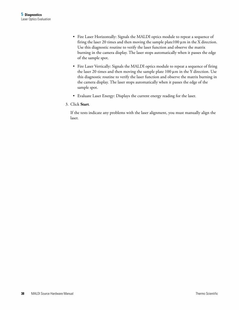
5 DiagnosticsLaser Optics Evaluation
• Fire Laser Horizontally: Signals the MALDI optics module to repeat a sequence of firing the laser 20 times and then moving the sample plate100 μm in the X direction. Use this diagnostic routine to verify the laser function and observe the matrix burning in the camera display. The laser stops automatically when it passes the edge of the sample spot.
• Fire Laser Vertically: Signals the MALDI optics module to repeat a sequence of firing the laser 20 times and then moving the sample plate 100 μm in the Y direction. Use this diagnostic routine to verify the laser function and observe the matrix burning in the camera display. The laser stops automatically when it passes the edge of the sample spot.
• Evaluate Laser Energy: Displays the current energy reading for the laser.
3. Click Start.
If the tests indicate any problems with the laser alignment, you must manually align the laser.
38 MALDI Source Hardware Manual Thermo Scientific
5 DiagnosticsMALDI System Evaluation
MALDI System EvaluationThe MALDI System Evaluation diagnostics provide tools for checking the functions of the hardware and firmware in the MALDI source. These tools test the firmware version and check the functions of the mechanical systems for handling the sample plate.
To check functions of the hardware and firmware in the MALDI source
1. In the Diagnostics dialog box, from the Test Name list, select MALDI System Evaluation from the Test Name list.
The MALDI System Evaluation test list opens (Figure 21).
Figure 21. MALDI System Evaluation test list
2. Select from the following options.
• Initialize MALDI Source: Signals the source to move the XYZ mechanism and pickup tray between their upper and lower limit switches. It also signals the source to pump down the sample chamber if the chamber is already closed.
Note If for any reason the MALDI source becomes unstable and is not responding, run the Initialize MALDI Source diagnostic.
Thermo Scientific MALDI Source Hardware Manual 39
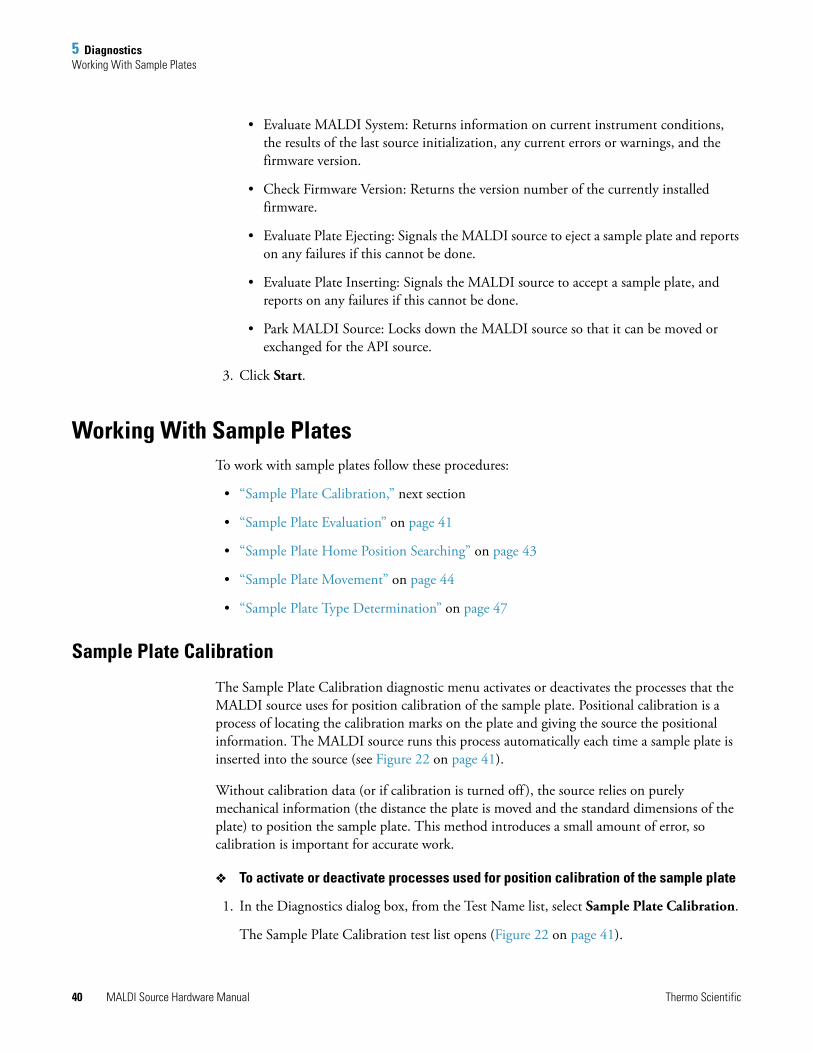
5 DiagnosticsWorking With Sample Plates
• Evaluate MALDI System: Returns information on current instrument conditions, the results of the last source initialization, any current errors or warnings, and the firmware version.
• Check Firmware Version: Returns the version number of the currently installed firmware.
• Evaluate Plate Ejecting: Signals the MALDI source to eject a sample plate and reports on any failures if this cannot be done.
• Evaluate Plate Inserting: Signals the MALDI source to accept a sample plate, and reports on any failures if this cannot be done.
• Park MALDI Source: Locks down the MALDI source so that it can be moved or exchanged for the API source.
3. Click Start.
Working With Sample PlatesTo work with sample plates follow these procedures:
• “Sample Plate Calibration,” next section
• “Sample Plate Evaluation” on page 41
• “Sample Plate Home Position Searching” on page 43
• “Sample Plate Movement” on page 44
• “Sample Plate Type Determination” on page 47
Sample Plate Calibration
The Sample Plate Calibration diagnostic menu activates or deactivates the processes that the MALDI source uses for position calibration of the sample plate. Positional calibration is a process of locating the calibration marks on the plate and giving the source the positional information. The MALDI source runs this process automatically each time a sample plate is inserted into the source (see Figure 22 on page 41).
Without calibration data (or if calibration is turned off ), the source relies on purely mechanical information (the distance the plate is moved and the standard dimensions of the plate) to position the sample plate. This method introduces a small amount of error, so calibration is important for accurate work.
To activate or deactivate processes used for position calibration of the sample plate
1. In the Diagnostics dialog box, from the Test Name list, select Sample Plate Calibration.
The Sample Plate Calibration test list opens (Figure 22 on page 41).
40 MALDI Source Hardware Manual Thermo Scientific
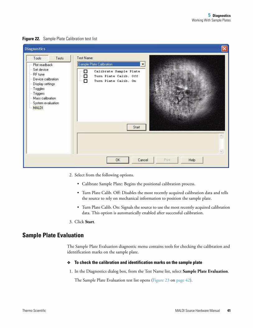
5 DiagnosticsWorking With Sample Plates
Figure 22. Sample Plate Calibration test list
2. Select from the following options.
• Calibrate Sample Plate: Begins the positional calibration process.
• Turn Plate Calib. Off: Disables the most recently acquired calibration data and tells the source to rely on mechanical information to position the sample plate.
• Turn Plate Calib. On: Signals the source to use the most recently acquired calibration data. This option is automatically enabled after successful calibration.
3. Click Start.
Sample Plate Evaluation
The Sample Plate Evaluation diagnostic menu contains tools for checking the calibration and identification marks on the sample plate.
To check the calibration and identification marks on the sample plate
1. In the Diagnostics dialog box, from the Test Name list, select Sample Plate Evaluation.
The Sample Plate Evaluation test list opens (Figure 23 on page 42).
Thermo Scientific MALDI Source Hardware Manual 41
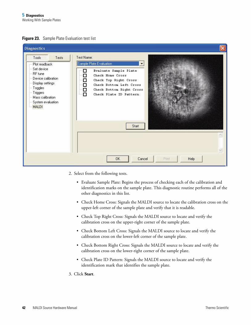
5 DiagnosticsWorking With Sample Plates
Figure 23. Sample Plate Evaluation test list
2. Select from the following tests.
• Evaluate Sample Plate: Begins the process of checking each of the calibration and identification marks on the sample plate. This diagnostic routine performs all of the other diagnostics in this list.
• Check Home Cross: Signals the MALDI source to locate the calibration cross on the upper-left corner of the sample plate and verify that it is readable.
• Check Top Right Cross: Signals the MALDI source to locate and verify the calibration cross on the upper-right corner of the sample plate.
• Check Bottom Left Cross: Signals the MALDI source to locate and verify the calibration cross on the lower-left corner of the sample plate.
• Check Bottom Right Cross: Signals the MALDI source to locate and verify the calibration cross on the lower-right corner of the sample plate.
• Check Plate ID Pattern: Signals the MALDI source to locate and verify the identification mark that identifies the sample plate.
3. Click Start.
42 MALDI Source Hardware Manual Thermo Scientific
5 DiagnosticsWorking With Sample Plates
Sample Plate Home Position Searching
The Sample Plate Home Position Searching diagnostic menu contains tools to locate the home position either automatically or manually.
To locate the sample plate home position
1. In the Diagnostics dialog box, from the Test Name list, select Sample Plate Home Position Searching.
The Sample Plate Home Position Searching test list opens (Figure 24).
Figure 24. Sample Plate Home Position Searching test list
2. Select from the following options:
• Auto Find Home Position: Signals the source to locate the home cross in the upper-left corner of the sample plate, bring the home cross to the center of the camera field, and set that position as “home.”
The Auto Find Home Position command is the best way to locate the home calibration cross and set the home position. If that command fails, then the most likely cause is one of the following:
–The camera is out of alignment. In this case, run a full video calibration as described in “Running a Full Video Calibration” on page 55.
Thermo Scientific MALDI Source Hardware Manual 43
5 DiagnosticsWorking With Sample Plates
–The camera aperture is too small. In this case the camera display appears dark. You might need to adjust the aperture, as described in “Fine Position Map is Misaligned” on page 64.
–The camera aperture is too large. In this case the camera display appears too bright. You might need to adjust the aperture, also described in “Fine Position Map is Misaligned” on page 64.
–The camera is not focusing properly. You might need to adjust the focus, as described in “Camera Focus is Out of Adjustment” on page 64.
–The optical illuminator is not putting enough light on the sample plate because the illuminator LED is bad, the illuminator fiber is broken, or something is blocking the light.
–Something is obscuring the identifier mark on the sample plate.
If you are unable to rule out or repair all of these causes, you can move the plate manually using the Go to Home Position command. You may also move the sample plate using the mouse. Click any point in the camera display to signal the MALDI source to center the camera display on that point. However, these are stopgap measures only, until you identify and repair the problem that is preventing the Auto Find Home Position command from working properly.
• Go to Home Position: Moves the sample plate to the last set “home” position.
• Set Home Position: Sets the home position manually, wherever the camera display is centered.
• Reset Home Position: Resets the home position to the manufacturing default location.
3. Click Start.
Sample Plate Movement
The Sample Plate Movement list contains tools for testing the movement of the XYZ mechanism as it holds the sample plate. These commands also help you check the accuracy of the plate calibration information.
To test the movement of the XYZ mechanism
1. In the Diagnostics dialog box, from the Test Name list, select Sample Plate Movement.
Note If the optical illuminator in your MALDI source is defective, contact Thermo Fisher Scientific Technical Support or a field service engineer.
Note The Set Home Position command cannot be undone. Once it is set, the only way to reset the home position is to run this command again or use the Auto Find Home Position command.
44 MALDI Source Hardware Manual Thermo Scientific
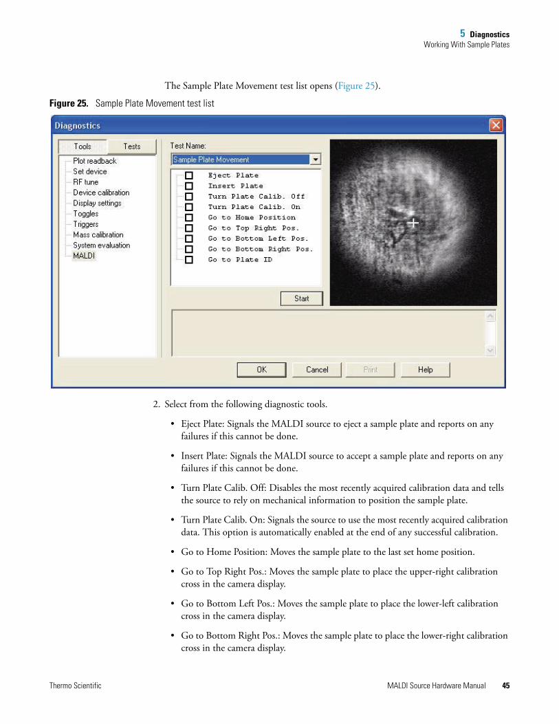
5 DiagnosticsWorking With Sample Plates
The Sample Plate Movement test list opens (Figure 25).
Figure 25. Sample Plate Movement test list
2. Select from the following diagnostic tools.
• Eject Plate: Signals the MALDI source to eject a sample plate and reports on any failures if this cannot be done.
• Insert Plate: Signals the MALDI source to accept a sample plate and reports on any failures if this cannot be done.
• Turn Plate Calib. Off: Disables the most recently acquired calibration data and tells the source to rely on mechanical information to position the sample plate.
• Turn Plate Calib. On: Signals the source to use the most recently acquired calibration data. This option is automatically enabled at the end of any successful calibration.
• Go to Home Position: Moves the sample plate to the last set home position.
• Go to Top Right Pos.: Moves the sample plate to place the upper-right calibration cross in the camera display.
• Go to Bottom Left Pos.: Moves the sample plate to place the lower-left calibration cross in the camera display.
• Go to Bottom Right Pos.: Moves the sample plate to place the lower-right calibration cross in the camera display.
Thermo Scientific MALDI Source Hardware Manual 45
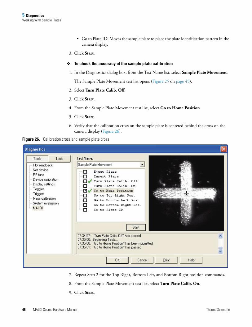
5 DiagnosticsWorking With Sample Plates
• Go to Plate ID: Moves the sample plate to place the plate identification pattern in the camera display.
3. Click Start.
To check the accuracy of the sample plate calibration
1. In the Diagnostics dialog box, from the Test Name list, select Sample Plate Movement.
The Sample Plate Movement test list opens (Figure 25 on page 45).
2. Select Turn Plate Calib. Off.
3. Click Start.
4. From the Sample Plate Movement test list, select Go to Home Position.
5. Click Start.
6. Verify that the calibration cross on the sample plate is centered behind the cross on the camera display (Figure 26).
Figure 26. Calibration cross and sample plate cross
7. Repeat Step 2 for the Top Right, Bottom Left, and Bottom Right position commands.
8. From the Sample Plate Movement test list, select Turn Plate Calib. On.
9. Click Start.
46 MALDI Source Hardware Manual Thermo Scientific
5 DiagnosticsWorking With Sample Plates
If all four calibration crosses are properly centered, then the plate is properly calibrated. If not, then recalibrate the plate.
Sample Plate Type Determination
Use the Sample Plate Type Determination diagnostic menu to set the sample plate type manually. The plate type is critical for properly mapping the plate. Use the Autoconfig Plate Type command in most cases. Use the manual set commands to set the plate type only when the automatic command fails.
To set the sample plate type
1. In the Diagnostics dialog box, from the Test Name list, select Sample Plate Type Determination.
The Sample Plate Type Determination test list opens (Figure 27 on page 48).
Note If you insert a tissue imaging plate without the tissue imaging license installed, the plate type defaults to the Thermo 96 Well Plate. You can use this menu to set the plate type to a tissue imaging plate, but the Tissue Imaging tab is not shown in the MALDI source dialog box.
If the diagnostics cannot determine the sample plate type, the plate type defaults to a Thermo 96 Well Plate.
Thermo Scientific MALDI Source Hardware Manual 47
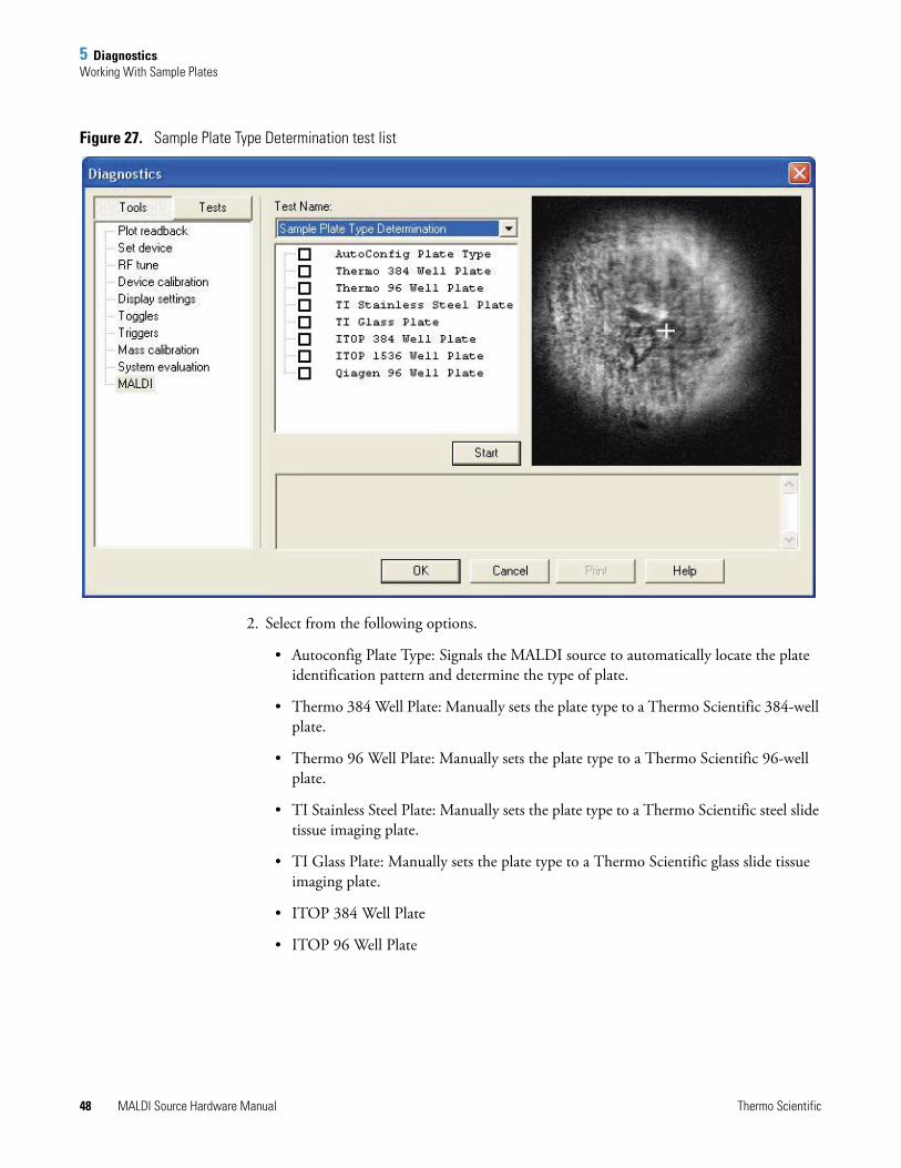
5 DiagnosticsWorking With Sample Plates
Figure 27. Sample Plate Type Determination test list
2. Select from the following options.
• Autoconfig Plate Type: Signals the MALDI source to automatically locate the plate identification pattern and determine the type of plate.
• Thermo 384 Well Plate: Manually sets the plate type to a Thermo Scientific 384-well plate.
• Thermo 96 Well Plate: Manually sets the plate type to a Thermo Scientific 96-well plate.
• TI Stainless Steel Plate: Manually sets the plate type to a Thermo Scientific steel slide tissue imaging plate.
• TI Glass Plate: Manually sets the plate type to a Thermo Scientific glass slide tissue imaging plate.
• ITOP 384 Well Plate
• ITOP 96 Well Plate
48 MALDI Source Hardware Manual Thermo Scientific
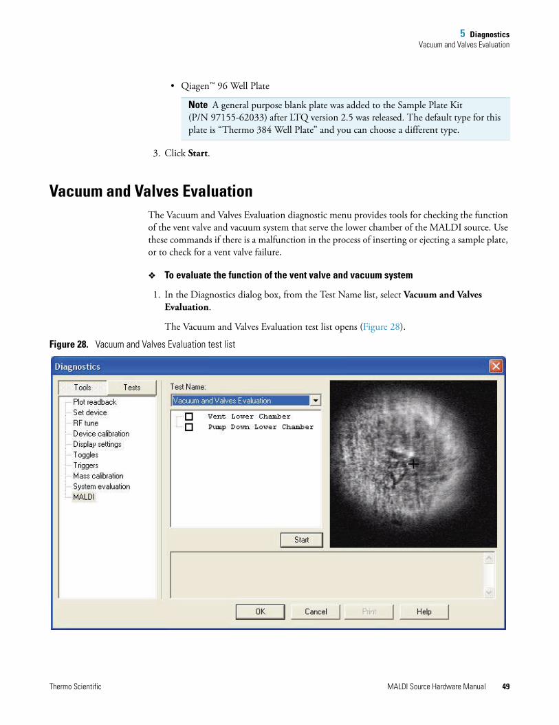
5 DiagnosticsVacuum and Valves Evaluation
• Qiagen™ 96 Well Plate
3. Click Start.
Vacuum and Valves EvaluationThe Vacuum and Valves Evaluation diagnostic menu provides tools for checking the function of the vent valve and vacuum system that serve the lower chamber of the MALDI source. Use these commands if there is a malfunction in the process of inserting or ejecting a sample plate, or to check for a vent valve failure.
To evaluate the function of the vent valve and vacuum system
1. In the Diagnostics dialog box, from the Test Name list, select Vacuum and Valves Evaluation.
The Vacuum and Valves Evaluation test list opens (Figure 28).
Figure 28. Vacuum and Valves Evaluation test list
Note A general purpose blank plate was added to the Sample Plate Kit (P/N 97155-62033) after LTQ version 2.5 was released. The default type for this plate is “Thermo 384 Well Plate” and you can choose a different type.
Thermo Scientific MALDI Source Hardware Manual 49
5 DiagnosticsTuning the Video Camera
2. Select from the following diagnostic tools.
• Vent Lower Chamber: Signals the MALDI source to open the vent valve in the load lock and vent the chamber to atmosphere. The vacuum in the upper chamber, which contains the XYZ mechanisms, is not affected.
• Pump Down Lower Chamber: Signals the MALDI source to pump the load lock down to approximately 100 mTorr.
3. Click Start.
Tuning the Video CameraTo tune the video camera, perform these diagnostics:
• “Video Camera Auto Calibration,” next section
• “Video Camera Manual Calibration” on page 52
• “Video Camera Contrast and Brightness” on page 54
Video Camera Auto Calibration
Use the Video Camera Auto Calibration diagnostic menu to calibrate the camera automatically. There are two components to this process: position calibration, in which the camera is centered on the calibration cross on the sample plate, and dimension calibration in which the system measures the relationship of a pixel of movement on the camera display to the actual movement of the XYZ mechanism.
Note In order to run the diagnostics, you must have a sample plate loaded in the MALDI source.
50 MALDI Source Hardware Manual Thermo Scientific
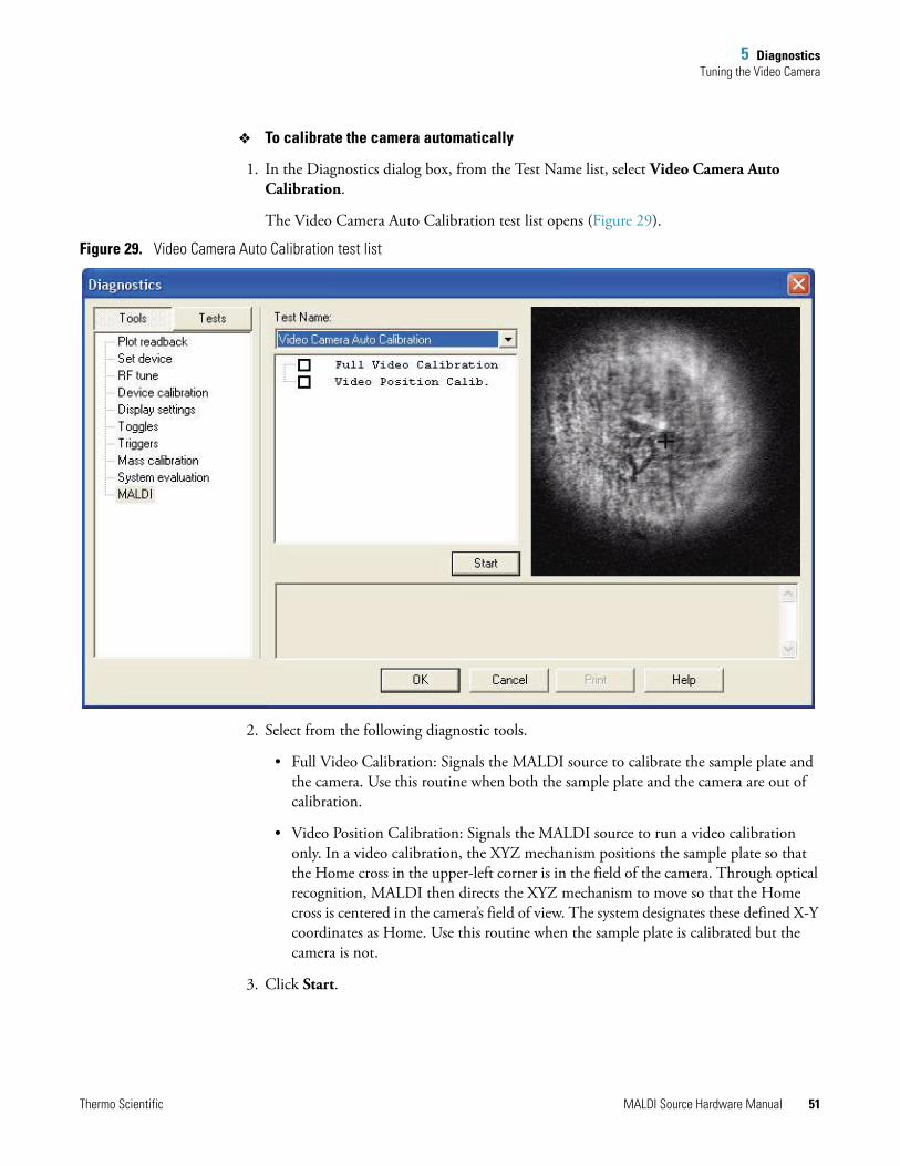
5 DiagnosticsTuning the Video Camera
To calibrate the camera automatically
1. In the Diagnostics dialog box, from the Test Name list, select Video Camera Auto Calibration.
The Video Camera Auto Calibration test list opens (Figure 29).
Figure 29. Video Camera Auto Calibration test list
2. Select from the following diagnostic tools.
• Full Video Calibration: Signals the MALDI source to calibrate the sample plate and the camera. Use this routine when both the sample plate and the camera are out of calibration.
• Video Position Calibration: Signals the MALDI source to run a video calibration only. In a video calibration, the XYZ mechanism positions the sample plate so that the Home cross in the upper-left corner is in the field of the camera. Through optical recognition, MALDI then directs the XYZ mechanism to move so that the Home cross is centered in the camera’s field of view. The system designates these defined X-Y coordinates as Home. Use this routine when the sample plate is calibrated but the camera is not.
3. Click Start.
Thermo Scientific MALDI Source Hardware Manual 51
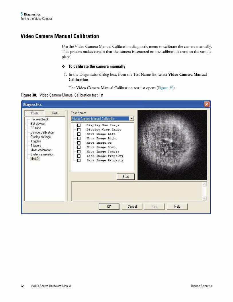
5 DiagnosticsTuning the Video Camera
Video Camera Manual Calibration
Use the Video Camera Manual Calibration diagnostic menu to calibrate the camera manually. This process makes certain that the camera is centered on the calibration cross on the sample plate.
To calibrate the camera manually
1. In the Diagnostics dialog box, from the Test Name list, select Video Camera Manual Calibration.
The Video Camera Manual Calibration test list opens (Figure 30).
Figure 30. Video Camera Manual Calibration test list
52 MALDI Source Hardware Manual Thermo Scientific
5 DiagnosticsTuning the Video Camera
2. Select from the following diagnostic tools.
• Display Raw Image: Places the raw, unprocessed camera feed in the video display box. The raw image is uncorrected for the oblique viewing angle and contains edge images such as portions of the ion transfer quadrupole. A rectangle superimposed on the raw image defines the field that is used to produce the cropped image. When properly positioned, the raw image is centered in this rectangle.
• Display Crop Image: Places the cropped and processed camera feed in the video display box. This image is digitally processed based on the last saved parameters for the crop rectangle to refine the field of view and correct for the oblique angle. The images then appear as they would looking straight down on the sample plate.
3. Use the following options only on the raw image. After you run these commands and save the resulting changes, you must recalibrate the camera display for position and dimension.
• Move Image Left: Shifts the crop rectangle to the left.
• Move Image Right: Shifts the crop rectangle to the right.
• Move Image Up: Shifts the crop rectangle upward.
• Move Image Down: Shifts the crop rectangle downward.
• Move Image Center: Centers the crop rectangle in the raw image.
• Load Image Property: Undoes any changes to the crop rectangle and reloads the last saved values.
• Save Image Property: Saves the current parameters for the crop rectangle.
4. Click Start.
Thermo Scientific MALDI Source Hardware Manual 53
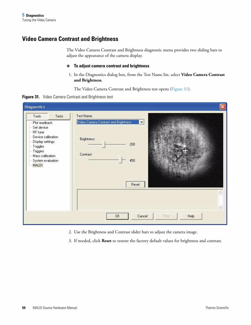
5 DiagnosticsTuning the Video Camera
Video Camera Contrast and Brightness
The Video Camera Contrast and Brightness diagnostic menu provides two sliding bars to adjust the appearance of the camera display.
To adjust camera contrast and brightness
1. In the Diagnostics dialog box, from the Test Name list, select Video Camera Contrast and Brightness.
The Video Camera Contrast and Brightness test opens (Figure 31).
Figure 31. Video Camera Contrast and Brightness test
2. Use the Brightness and Contrast slider bars to adjust the camera image.
3. If needed, click Reset to restore the factory default values for brightness and contrast.
54 MALDI Source Hardware Manual Thermo Scientific
5 DiagnosticsPreparing a Thin-Layer Matrix Sample
Preparing a Thin-Layer Matrix SampleSome of the procedures that follow require a special sample consisting of a thin, even layer of matrix with no analytes included.
To prepare a thin-layer matrix sample
1. Prepare 1mL of a saturated solution of any standard MALDI matrix material (for example, α-cyano-4-hydroxycinammic acid) in 100% HPLC-grade acetone.
2. Spot at least 10μL of the saturated solution onto at least a clean A1 position sample well on a MALDI sample plate.
3. Allow the matrix to dry naturally. Do not heat the sample plate or place it in vacuum to accelerate the drying process.
Running a Full Video CalibrationUse full video calibration when both the sample plate and the camera are out of calibration.
Before performing this procedure, prepare a thin-layer matrix sample plate so that the matrix is deposited over the entire sample area of the sample plate. See “Preparing a Thin-Layer Matrix Sample” on page 55.
Note The matrix solution may spread out beyond the edges of the sample well, but the solution must not touch any other well that contains a sample. To prevent spreading into other wells, spot the saturated solution in a sample well that has at least one clean well adjacent to it on each side, for a 96-well sample plate. For a 384-well sample plate, select a sample well that has at least two clean wells in all directions.
When preparing a sample plate for a full video calibration, coat the entire sample area of the plate with matrix. (The sample area is the sample wells and the area around them.) Avoid applying matrix to the calibration crosses and the plate identification mark.
Note The sample area is the sample wells and the area around them. Avoid applying matrix to the calibration crosses and the plate identification mark.
Thermo Scientific MALDI Source Hardware Manual 55
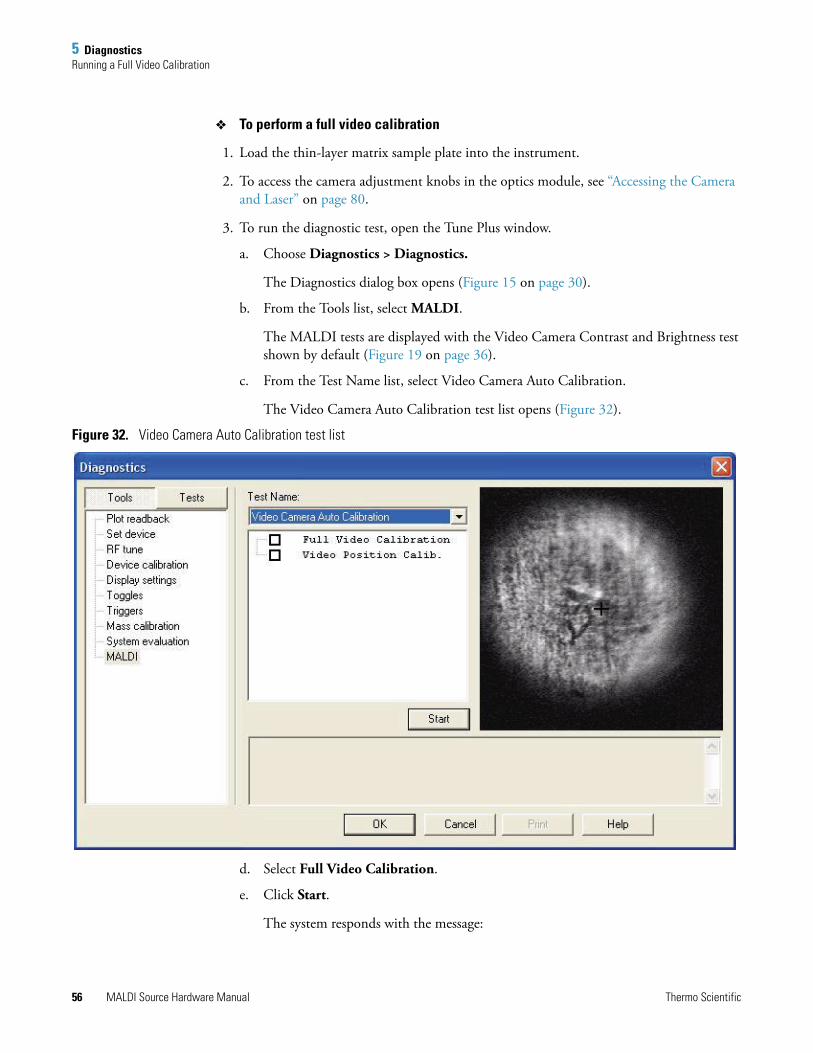
5 DiagnosticsRunning a Full Video Calibration
To perform a full video calibration
1. Load the thin-layer matrix sample plate into the instrument.
2. To access the camera adjustment knobs in the optics module, see “Accessing the Camera and Laser” on page 80.
3. To run the diagnostic test, open the Tune Plus window.
a. Choose Diagnostics > Diagnostics.
The Diagnostics dialog box opens (Figure 15 on page 30).
b. From the Tools list, select MALDI.
The MALDI tests are displayed with the Video Camera Contrast and Brightness test shown by default (Figure 19 on page 36).
c. From the Test Name list, select Video Camera Auto Calibration.
The Video Camera Auto Calibration test list opens (Figure 32).
Figure 32. Video Camera Auto Calibration test list
d. Select Full Video Calibration.
e. Click Start.
The system responds with the message:
56 MALDI Source Hardware Manual Thermo Scientific
5 DiagnosticsRunning a Full Video Calibration
If your sample plate is well calibrated, you don’t need to run the procedure. Run video position calibration procedure. Are you sure you want to calibrate video system?
f. Click OK.
The system responds with the message:
Do you have a special sample plate for video calibration?
g. Click OK.
The system responds with the message:
Focus the camera to the optical hole to make a well-defined circle.
4. If needed, adjust the camera aperture and focus until the CD camera display shows a bright, well-defined oval.
5. In the Diagnostics dialog box, click OK.
The system responds with the message:
Focus the camera back to the sample plate, and secure the camera.
6. Carefully adjust the zoom and aperture of the camera until a sharp, well-defined cross is visible in the camera display.
7. Click OK. The MALDI source automatically calibrates the sample plate.
The system responds with the message:
Are you sure you want to overwrite the previous saved image property with the current one?
8. Click OK.
9. Eject the thin-layer matrix sample plate from the instrument.
10. Reinstall the optics module cover and the LTQ XL top cover.
Note The aperture control is the smaller knurled ring behind the focus adjustment. Rotate this smaller ring clockwise to close the aperture and counterclockwise to open the aperture.
The focus adjustment is the large knurled ring at the front of the camera. The focus adjustment slides in and out along the barrel of the camera.
Thermo Scientific MALDI Source Hardware Manual 57

6
Troubleshooting
This chapter offers some examples of possible instrument problems, along with approaches to solving them.
Contents
• Camera Image Not Centered
• No Video Display from the Camera
• Sample Appears Too Dark or Too Light
• Camera Focus is Out of Adjustment
• Fine Position Map is Misaligned
• No Ions Detected
• Sample Plate Jams
• Sample Plate Does Not Load Correctly
• Sample Plate Calibration Fails
• Instrument Calibration Fails
• Increase in System Noise
• Control Module is Not Communicating
• Accessing the Camera and Laser
Thermo Scientific MALDI Source Hardware Manual 59
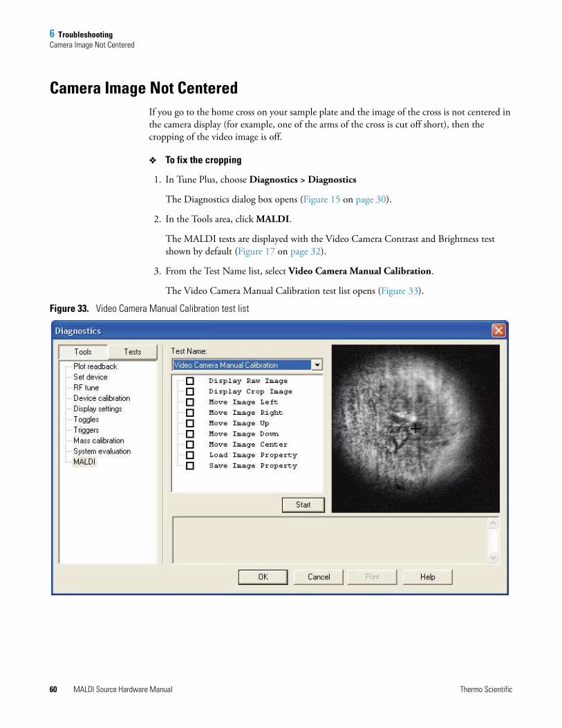
6 TroubleshootingCamera Image Not Centered
Camera Image Not CenteredIf you go to the home cross on your sample plate and the image of the cross is not centered in the camera display (for example, one of the arms of the cross is cut off short), then the cropping of the video image is off.
To fix the cropping
1. In Tune Plus, choose Diagnostics > Diagnostics
The Diagnostics dialog box opens (Figure 15 on page 30).
2. In the Tools area, click MALDI.
The MALDI tests are displayed with the Video Camera Contrast and Brightness test shown by default (Figure 17 on page 32).
3. From the Test Name list, select Video Camera Manual Calibration.
The Video Camera Manual Calibration test list opens (Figure 33).
Figure 33. Video Camera Manual Calibration test list
60 MALDI Source Hardware Manual Thermo Scientific
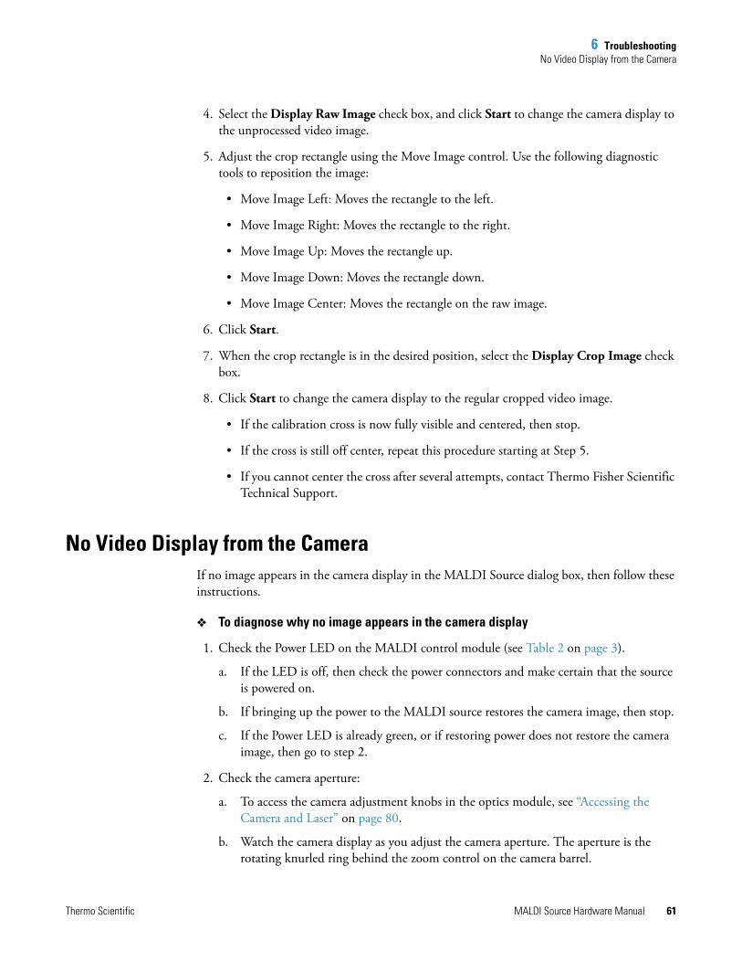
6 TroubleshootingNo Video Display from the Camera
4. Select the Display Raw Image check box, and click Start to change the camera display to the unprocessed video image.
5. Adjust the crop rectangle using the Move Image control. Use the following diagnostic tools to reposition the image:
• Move Image Left: Moves the rectangle to the left.
• Move Image Right: Moves the rectangle to the right.
• Move Image Up: Moves the rectangle up.
• Move Image Down: Moves the rectangle down.
• Move Image Center: Moves the rectangle on the raw image.
6. Click Start.
7. When the crop rectangle is in the desired position, select the Display Crop Image check box.
8. Click Start to change the camera display to the regular cropped video image.
• If the calibration cross is now fully visible and centered, then stop.
• If the cross is still off center, repeat this procedure starting at Step 5.
• If you cannot center the cross after several attempts, contact Thermo Fisher Scientific Technical Support.
No Video Display from the CameraIf no image appears in the camera display in the MALDI Source dialog box, then follow these instructions.
To diagnose why no image appears in the camera display
1. Check the Power LED on the MALDI control module (see Table 2 on page 3).
a. If the LED is off, then check the power connectors and make certain that the source is powered on.
b. If bringing up the power to the MALDI source restores the camera image, then stop.
c. If the Power LED is already green, or if restoring power does not restore the camera image, then go to step 2.
2. Check the camera aperture:
a. To access the camera adjustment knobs in the optics module, see “Accessing the Camera and Laser” on page 80.
b. Watch the camera display as you adjust the camera aperture. The aperture is the rotating knurled ring behind the zoom control on the camera barrel.
Thermo Scientific MALDI Source Hardware Manual 61
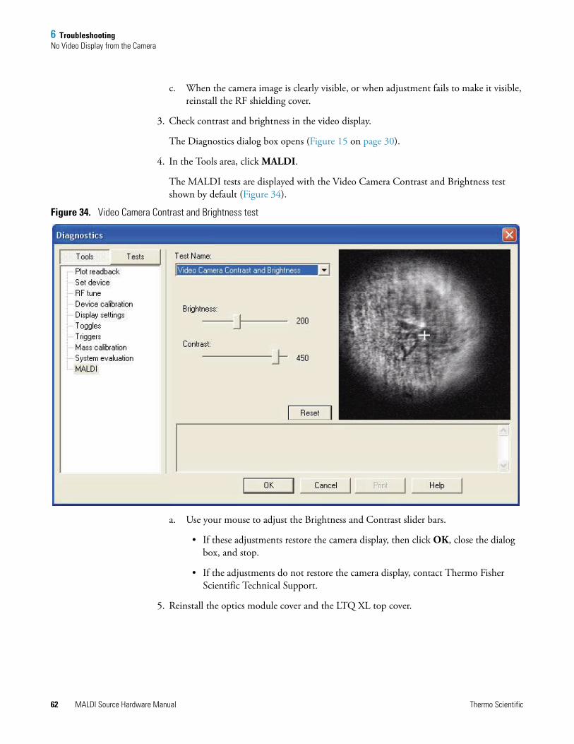
6 TroubleshootingNo Video Display from the Camera
c. When the camera image is clearly visible, or when adjustment fails to make it visible, reinstall the RF shielding cover.
3. Check contrast and brightness in the video display.
The Diagnostics dialog box opens (Figure 15 on page 30).
4. In the Tools area, click MALDI.
The MALDI tests are displayed with the Video Camera Contrast and Brightness test shown by default (Figure 34).
Figure 34. Video Camera Contrast and Brightness test
a. Use your mouse to adjust the Brightness and Contrast slider bars.
• If these adjustments restore the camera display, then click OK, close the dialog box, and stop.
• If the adjustments do not restore the camera display, contact Thermo Fisher Scientific Technical Support.
5. Reinstall the optics module cover and the LTQ XL top cover.
62 MALDI Source Hardware Manual Thermo Scientific
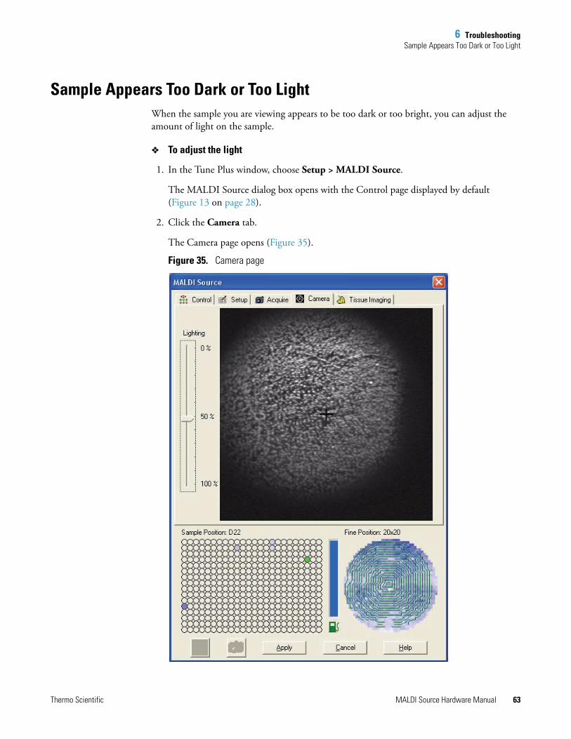
6 TroubleshootingSample Appears Too Dark or Too Light
Sample Appears Too Dark or Too LightWhen the sample you are viewing appears to be too dark or too bright, you can adjust the amount of light on the sample.
To adjust the light
1. In the Tune Plus window, choose Setup > MALDI Source.
The MALDI Source dialog box opens with the Control page displayed by default (Figure 13 on page 28).
2. Click the Camera tab.
The Camera page opens (Figure 35).
Figure 35. Camera page
Thermo Scientific MALDI Source Hardware Manual 63
6 TroubleshootingCamera Focus is Out of Adjustment
3. Use your mouse to adjust the Lighting slider bar until the sample you are viewing appears to have the correct amount of light.
4. Click Apply.
Camera Focus is Out of AdjustmentTo adjust the camera focus
1. To access the camera in the optics module, see “Accessing the Camera and Laser” on page 80.
2. Watch the camera display as you adjust the camera focus, which is the zoom control on the camera barrel. The zoom adjustment is the large knurled ring at the front of the camera. The zoom adjustment slides in and out along the barrel of the camera.
• If adjusting the camera focus restored the image, then stop.
• If adjusting the camera focus fails to restore the image, then contact Thermo Fisher Scientific Technical Support.
3. Reinstall the optics module cover and the LTQ XL top cover.
Fine Position Map is MisalignedIf the fine position sample spot map in the MALDI Source dialog box shows a division line or a cross down the center, then the aperture opening of the camera might be too wide. An excessively bright image in the camera display might also indicate that the aperture opening is too wide.
If the aperture is open too wide, it reduces the ability of the optical software to recognize and map the sample spot. An aperture that is too wide also limits the functions of the MALDI Crystal Positioning System (CPS).
To adjust the camera aperture
1. To access the camera in the optics module, see “Accessing the Camera and Laser” on page 80.
2. Watch the camera display as you adjust the camera aperture, which is the rotating knurled ring behind the zoom control on the camera barrel. Adjust the aperture until the camera display is in sharp contrast, but not too bright.
3. When the camera image is clear and sharp, or when adjustment fails to make the image clear, replace the angled cover on the side of the optical module and tighten the thumbscrews.
Note This setting is saved for future scans until you change it.
64 MALDI Source Hardware Manual Thermo Scientific
6 TroubleshootingNo Ions Detected
4. Reset the fine position sample spot map by clicking any other spot in the sample map. Click on the original spot to return to the original position.
• If adjusting the camera aperture restores the fine position sample spot map, then stop.
• If adjusting the camera aperture fails to restore the fine position sample spot map, then contact Thermo Fisher Scientific Technical Support.
5. Reinstall the optics module cover and the LTQ XL top cover.
No Ions DetectedUse the following procedures if the sample is visible in the camera, but when you activate the laser to collect ions for analysis, no ions are detected.
• “Determine if the Laser is Firing,” next section
• “Check the Ion Transfer Quadrupole” on page 67
• “Run a Multipole Calibration Check” on page 68
Determine if the Laser is Firing
To determine if the laser is firing
1. When you activate the laser, verify that the Laser LED on the MALDI sample module is flashing red.
2. Verify that the laser is reaching the sample.
a. Prepare a thin-layer matrix sample.
b. Load the sample plate into the MALDI source.
c. Use the Sample Position Map in the MALDI Source dialog box to position the sample well with the thin-layer matrix sample in the camera display.
d. In Tune Plus, choose Diagnostics > Diagnostics.
The Diagnostics dialog box opens (Figure 15 on page 30).
e. In the Tools list, select MALDI.
The MALDI tests are displayed with the Video Camera Contrast and Brightness test shown by default (Figure 17 on page 32.)
f. From the Test Name list, select Laser Optics Evaluation.
The Laser Optics Evaluation test list opens (Figure 36).
Thermo Scientific MALDI Source Hardware Manual 65
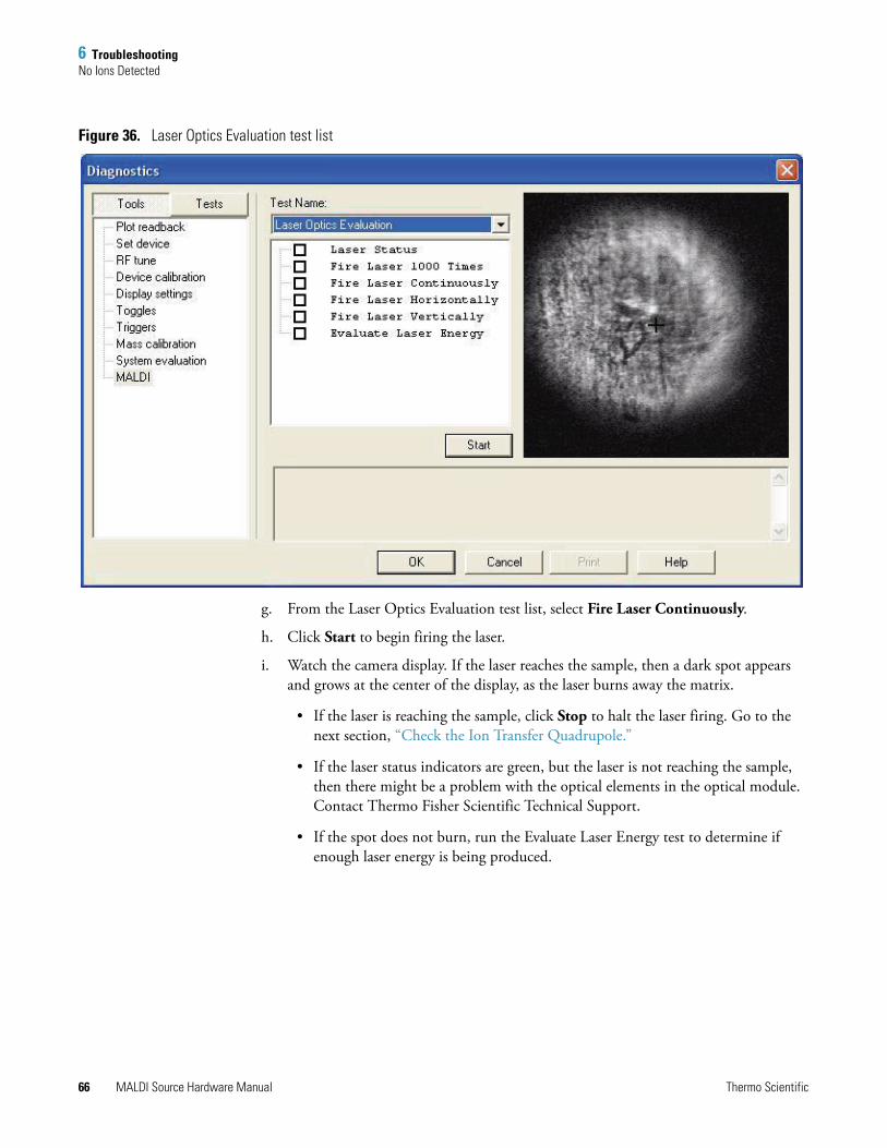
6 TroubleshootingNo Ions Detected
Figure 36. Laser Optics Evaluation test list
g. From the Laser Optics Evaluation test list, select Fire Laser Continuously.
h. Click Start to begin firing the laser.
i. Watch the camera display. If the laser reaches the sample, then a dark spot appears and grows at the center of the display, as the laser burns away the matrix.
• If the laser is reaching the sample, click Stop to halt the laser firing. Go to the next section, “Check the Ion Transfer Quadrupole.”
• If the laser status indicators are green, but the laser is not reaching the sample, then there might be a problem with the optical elements in the optical module. Contact Thermo Fisher Scientific Technical Support.
• If the spot does not burn, run the Evaluate Laser Energy test to determine if enough laser energy is being produced.
66 MALDI Source Hardware Manual Thermo Scientific
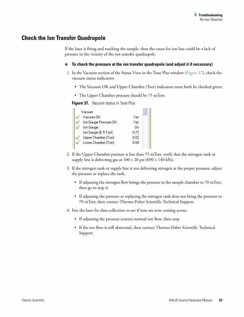
6 TroubleshootingNo Ions Detected
Check the Ion Transfer Quadrupole
If the laser is firing and reaching the sample, then the cause for ion loss could be a lack of pressure in the vicinity of the ion transfer quadrupole.
To check the pressure at the ion transfer quadrupole (and adjust it if necessary)
1. In the Vacuum section of the Status View in the Tune Plus window (Figure 37), check the vacuum status indicators:
• The Vacuum OK and Upper Chamber (Torr) indicators must both be checked green.
• The Upper Chamber pressure should be 75 mTorr.
Figure 37. Vacuum status in Tune Plus
2. If the Upper Chamber pressure is less than 75 mTorr, verify that the nitrogen tank or supply line is delivering gas at 100 ± 20 psi (690 ± 140 kPa).
3. If the nitrogen tank or supply line is not delivering nitrogen at the proper pressure, adjust the pressure or replace the tank.
• If adjusting the nitrogen flow brings the pressure in the sample chamber to 70 mTorr, then go to step 4.
• If adjusting the pressure or replacing the nitrogen tank does not bring the pressure to 70 mTorr, then contact Thermo Fisher Scientific Technical Support.
4. Fire the laser for data collection to see if ions are now coming across.
• If adjusting the pressure restores normal ion flow, then stop.
• If the ion flow is still abnormal, then contact Thermo Fisher Scientific Technical Support.
Thermo Scientific MALDI Source Hardware Manual 67
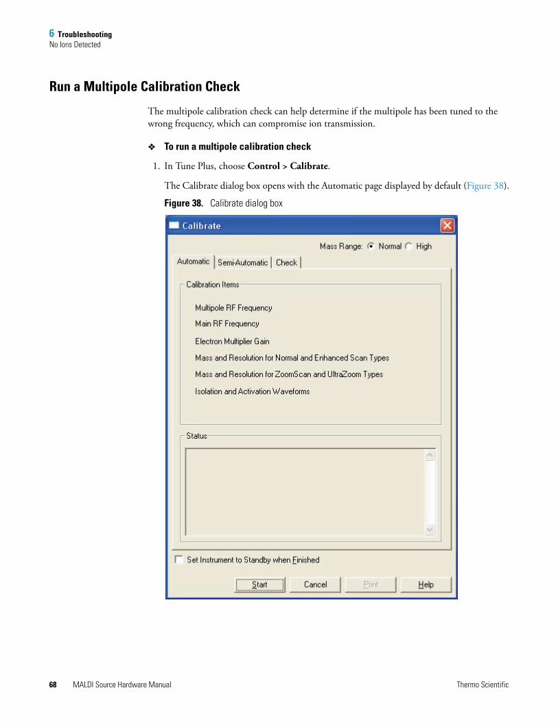
6 TroubleshootingNo Ions Detected
Run a Multipole Calibration Check
The multipole calibration check can help determine if the multipole has been tuned to the wrong frequency, which can compromise ion transmission.
To run a multipole calibration check
1. In Tune Plus, choose Control > Calibrate.
The Calibrate dialog box opens with the Automatic page displayed by default (Figure 38).
Figure 38. Calibrate dialog box
68 MALDI Source Hardware Manual Thermo Scientific
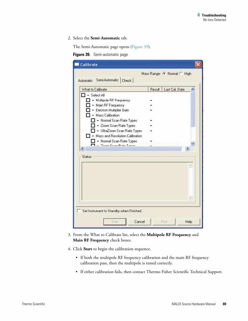
6 TroubleshootingNo Ions Detected
2. Select the Semi-Automatic tab.
The Semi-Automatic page opens (Figure 39).
Figure 39. Semi-automatic page
3. From the What to Calibrate list, select the Multipole RF Frequency and Main RF Frequency check boxes.
4. Click Start to begin the calibration sequence.
• If both the multipole RF frequency calibration and the main RF frequency calibration pass, then the multipole is tuned correctly.
• If either calibration fails, then contact Thermo Fisher Scientific Technical Support.
Thermo Scientific MALDI Source Hardware Manual 69
6 TroubleshootingSample Plate Jams
Sample Plate JamsA grinding noise coming from the MALDI source usually indicates that a sample plate has become jammed somewhere in the XYZ mechanism. If this situation occurs, then turn off the LTQ XL MS and contact Thermo Fisher Scientific Technical Support.
To prevent sample plates from jamming, follow the sample plate assembly instructions and observe the warnings in “Working With Sample Plates” in the MALDI Source Getting Started Guide.
Sample Plate Does Not Load CorrectlyOccasionally, a sample plate can fail to load properly and either becomes “lost” to the data system or is ejected. To resolve this problem, you must reset the MALDI source.
To reset the MALDI source
1. In Tune Plus, choose Diagnostics > Diagnostics.
The Diagnostics dialog box opens with the Tools list displayed by default (Figure 15 on page 30).
2. From the Tools list, select MALDI.
The MALDI tests are displayed with the Video Camera Contrast and Brightness test shown by default (Figure 31 on page 54).
3. From the Test Name list, select MALDI System Evaluation.
The MALDI System Evaluation test list opens (Figure 21 on page 39).
4. From the MALDI System Evaluation test list, select Initialize MALDI Source.
The LTQ XL resets the MALDI source. The sample plate can be ejected or the MALDI source can recognize the plate and you can proceed.
CAUTION Always use approved sample plates from Thermo Fisher Scientific with the MALDI source. Unapproved plates can jam and cause significant damage to the MALDI LTQ XL system.
CAUTION If the sample plate is not ejected or if there is a grinding noise coming from the MALDI source, see “Sample Plate Jams” on page 70.
70 MALDI Source Hardware Manual Thermo Scientific
6 TroubleshootingSample Plate Calibration Fails
Sample Plate Calibration FailsThe MALDI source runs through a plate calibration procedure each time you insert a sample plate.
To diagnose why a plate fails calibration
1. Check for sample or matrix material that might be obscuring the calibration marks.
a. In Tune Plus, choose Diagnostics > Diagnostics.
The Diagnostics dialog box opens with the Tools list displayed by default (Figure 15 on page 30).
b. From the Tools list, select MALDI.
The MALDI tests are displayed with the Video Camera Contrast and Brightness test shown by default (Figure 31 on page 54).
c. From the Test Name list, select Sample Plate Movement.
The Sample Plate Movement test list opens (Figure 40).
Note You must have a valid home position saved in order to perform this procedure. You might also need to run a full video calibration, in which case you need a second sample plate in addition to the one that failed calibration. See “Tuning the Video Camera” on page 50.
Thermo Scientific MALDI Source Hardware Manual 71
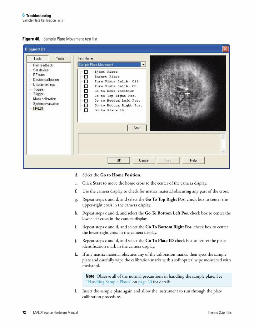
6 TroubleshootingSample Plate Calibration Fails
Figure 40. Sample Plate Movement test list
d. Select the Go to Home Position.
e. Click Start to move the home cross to the center of the camera display.
f. Use the camera display to check for matrix material obscuring any part of the cross.
g. Repeat steps c and d, and select the Go To Top Right Pos. check box to center the upper-right cross in the camera display.
h. Repeat steps c and d, and select the Go To Bottom Left Pos. check box to center the lower-left cross in the camera display.
i. Repeat steps c and d, and select the Go To Bottom Right Pos. check box to center the lower-right cross in the camera display.
j. Repeat steps c and d, and select the Go To Plate ID check box to center the plate identification mark in the camera display.
k. If any matrix material obscures any of the calibration marks, then eject the sample plate and carefully wipe the calibration marks with a soft optical wipe moistened with methanol.
l. Insert the sample plate again and allow the instrument to run through the plate calibration procedure.
Note Observe all of the normal precautions in handling the sample plate. See “Handling Sample Plates” on page 20 for details.
72 MALDI Source Hardware Manual Thermo Scientific
6 TroubleshootingSample Plate Calibration Fails
• If removing the obstructing matrix material results in a successful plate calibration, then stop.
• If there is no matrix material obscuring the calibration marks, or if removing the matrix material does not result in a successful plate calibration, then go to step 2.
2. Eject the sample plate from the instrument, and load the thin-layer matrix sample plate.
3. Perform a full video calibration procedure. See “Running a Full Video Calibration” on page 55.
4. Eject the thin-layer matrix sample plate from the instrument, and load the original sample plate.
• If the original sample plate passes calibration, then stop.
• If the original sample plate still fails calibration, then go to step 5.
5. Check for a defective sample plate.
a. In Tune Plus, choose Diagnostics > Diagnostics.
The Diagnostics dialog box opens with the Tools list displayed by default (Figure 15 on page 30).
b. From the Tools list, select MALDI.
The MALDI tests are displayed with the Video Camera Contrast and Brightness test shown by default (Figure 31 on page 54).
c. From the Test list, select Sample Plate Evaluation.
The Sample Plate Evaluation test list opens (Figure 41).
Thermo Scientific MALDI Source Hardware Manual 73
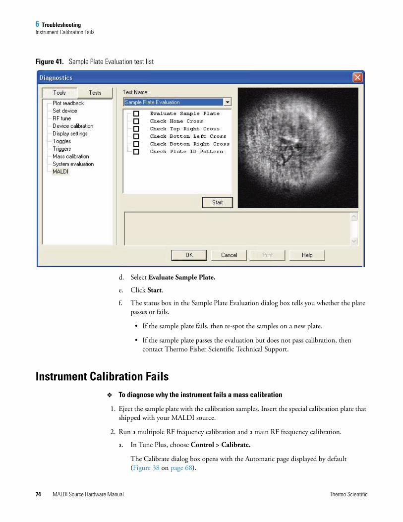
6 TroubleshootingInstrument Calibration Fails
Figure 41. Sample Plate Evaluation test list
d. Select Evaluate Sample Plate.
e. Click Start.
f. The status box in the Sample Plate Evaluation dialog box tells you whether the plate passes or fails.
• If the sample plate fails, then re-spot the samples on a new plate.
• If the sample plate passes the evaluation but does not pass calibration, then contact Thermo Fisher Scientific Technical Support.
Instrument Calibration FailsTo diagnose why the instrument fails a mass calibration
1. Eject the sample plate with the calibration samples. Insert the special calibration plate that shipped with your MALDI source.
2. Run a multipole RF frequency calibration and a main RF frequency calibration.
a. In Tune Plus, choose Control > Calibrate.
The Calibrate dialog box opens with the Automatic page displayed by default (Figure 38 on page 68).
74 MALDI Source Hardware Manual Thermo Scientific
6 TroubleshootingInstrument Calibration Fails
b. Select the Semi-Automatic tab.
The Semi-Automatic page opens (Figure 39 on page 69).
c. From the What to Calibrate list, select the Multipole RF Frequency and Main RF Frequency check boxes.
d. Click Start to begin the calibration sequence.
• If both the multipole RF frequency calibration and the main RF frequency calibration pass, then go to step 3.
• If either calibration fails, then contact Thermo Fisher Scientific Technical Support.
3. Prepare a new calibration sample using fresh solvents and freshly-prepared matrix solution.
4. Prepare sample spots according to the standard calibration procedure. Refer to the LTQ XL Series Getting Connected Guide for instructions.
5. In the Vacuum section of the Status View in the Tune Plus window (Figure 37 on page 67) check the Vacuum OK and Upper Chamber (Torr) status indicators. Both must be checked green, with the upper chamber pressure reading 170 mTorr.
a. If the pressure status indicators are satisfactory, then go to step 6.
b. If either pressure indicator is marked red, then adjust the vacuum. If the vacuum level is too low, then verify that the nitrogen sheath gas is flowing properly. If the vacuum is too high, then check your system for leaks.
6. Insert the sample plate with prepared calibration spots into the MALDI source.
7. Tune the laser energy.
a. In the MALDI Source dialog box (see Figure 13 on page 28), Control page, adjust the value of the Laser Energy in the Laser Settings area to improve the signal according to the guidelines in Table 5.
Table 5. Guidelines for adjusting MALDI laser energy
Problem Solution
No signal Increase laser energy.
Low signal Increase laser energy.
High baseline Decrease laser energy.
High signal, low baseline, and poor mass resolution Decrease laser energy in small increments.
High chemical noise Decrease laser energy.
Peak broadening and shifting to higher mass values (space charge effects)
Decrease laser energy.
Thermo Scientific MALDI Source Hardware Manual 75
6 TroubleshootingInstrument Calibration Fails
b. Make initial adjustments in increments (or decrements) of 10, and then make finer adjustments in smaller increments. After each adjustment, fire the laser once and check the mass spectrum in the Tune Plus window.
• When you are satisfied with the mass spectrum, go to step 8.
• If you cannot obtain a satisfactory mass spectrum by adjusting the laser energy, then contact Thermo Fisher Scientific Technical Support.
8. On the Semi-automatic page (Figure 39 on page 69), select the Electron Multiplier Gain check box.
9. Click Start to begin the calibration sequence. Wait until the electron multiplier gain calibration has finished before proceeding.
• If the calibration succeeds, then go to step 10.
• If the calibration fails, then go to step 20.
10. On the Semi-automatic page (Figure 39 on page 69), select the Normal Scan Rate Types check boxes under both Mass Calibration and Mass and Resolution Calibration.
11. Click Start to begin the calibration sequence. Wait until the calibrations have finished before proceeding.
• If both calibrations succeed, then go to step 12.
• If either calibration fails, then go to step 20.
12. On the Semi-automatic page (Figure 39 on page 69), select the Zoom Scan Rate Types check boxes under both Mass Calibration and Mass and Resolution Calibration.
13. Click Start to begin the calibration sequence. Wait until the calibrations have finished before proceeding.
• If both calibrations succeed, then go to step 14.
• If either calibration fails, then go to step 20.
14. On the Semi-automatic page (Figure 39 on page 69), select the Isolation Waveforms check box.
15. Click Start to begin the calibration sequence. Wait until the isolation waveform calibration has finished before proceeding.
• If the calibration succeeds, then go to step 16.
• If the calibration fails, then go to step 20.
16. On the Semi-automatic page (Figure 39 on page 69), select the Ultrazoom Scan Rate Types check boxes under the Mass Calibration and Mass and Resolution Calibration lists.
76 MALDI Source Hardware Manual Thermo Scientific
6 TroubleshootingIncrease in System Noise
17. Click Start to begin the calibration sequence. Wait until the calibrations have finished before proceeding.
• If both calibrations succeed, then go to step 18.
• If either calibration fails, then go to step 20.
18. On the Semi-automatic page (Figure 39 on page 69), select the Activation Waveforms check box.
19. Click Start to begin the calibration sequence. Wait until the activation waveform calibration has finished before proceeding.
• If the calibration succeeds, then stop. Your instrument is calibrated.
• If the calibration fails, then go to step 20.
20. If one or more of these calibrations fail, then run them again. Repeat a calibration up to three times if necessary. If a calibration fails three times, then contact Thermo Fisher Scientific Technical Support.
Increase in System NoiseIf the system begins producing unusually high levels of noise, first determine whether it is electronic noise or chemical noise.
Electronic Noise
This type of noise results from random electronic signals in or near your equipment. It is characterized by large signal spikes at random points in a mass spectrum.
To determine if the noise is coming from the LTQ XL MS
1. In Tune Plus, choose Diagnostics > Diagnostics.
The Diagnostics dialog box opens with the Tools list displayed by default (Figure 15 on page 30).
2. Click the Tests button.
The list of system-level tests opens with the General/All tests displayed by default (Figure 42).
Thermo Scientific MALDI Source Hardware Manual 77
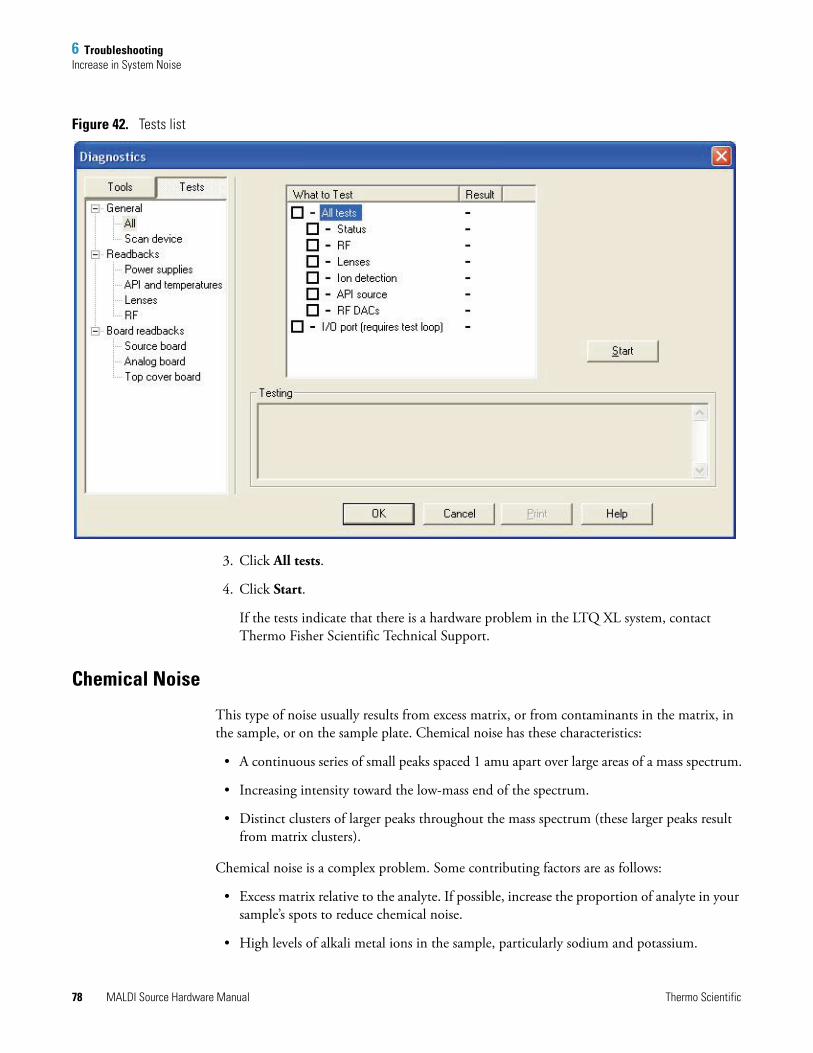
6 TroubleshootingIncrease in System Noise
Figure 42. Tests list
3. Click All tests.
4. Click Start.
If the tests indicate that there is a hardware problem in the LTQ XL system, contact Thermo Fisher Scientific Technical Support.
Chemical Noise
This type of noise usually results from excess matrix, or from contaminants in the matrix, in the sample, or on the sample plate. Chemical noise has these characteristics:
• A continuous series of small peaks spaced 1 amu apart over large areas of a mass spectrum.
• Increasing intensity toward the low-mass end of the spectrum.
• Distinct clusters of larger peaks throughout the mass spectrum (these larger peaks result from matrix clusters).
Chemical noise is a complex problem. Some contributing factors are as follows:
• Excess matrix relative to the analyte. If possible, increase the proportion of analyte in your sample’s spots to reduce chemical noise.
• High levels of alkali metal ions in the sample, particularly sodium and potassium.
78 MALDI Source Hardware Manual Thermo Scientific
6 TroubleshootingControl Module is Not Communicating
• Excessive laser energy.
• Contaminants on the sample plate.
If chemical noise persists, contact Thermo Fisher Scientific Technical Support.
It is best to take a preventive approach to chemical noise. To minimize this problem, observe the following precautions:
• Clean the sample plate regularly. Refer to the MALDI Source Getting Started Guide for information about cleaning the sample plate.
• Take all recommended precautions when cleaning or handling the sample plate. See “Handling Sample Plates” on page 20.
• Develop regular, reproducible procedures for preparing sample and matrix solutions, and for spotting samples on the sample plate.
• If you prepare matrix solutions in bulk, then develop a protocol for storing these solutions and disposing of any unused portions on a regular basis.
Control Module is Not CommunicatingIf you cannot send commands to the instrument, or if the Communication LED on the MALDI control module is not green, then the control module is not communicating with the instrument.
To diagnose why the control module is not in sync with the instrument
1. Verify the connections on all cables that connect the MALDI control module with the LTQ XL MS detector.
• If securing the cables restores communication, then stop.
• If securing the cables does not restore communication, then go to step 2.
2. Reboot the LTQ XL MS and the MALDI source by pressing the Reset button located on the left side of the LTQ XL power entry panel (Figure 43 on page 80).
Thermo Scientific MALDI Source Hardware Manual 79
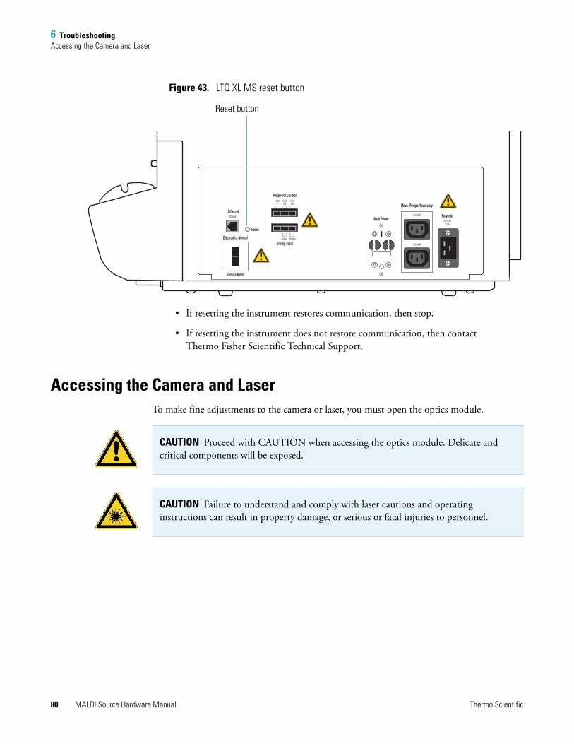
6 TroubleshootingAccessing the Camera and Laser
Figure 43. LTQ XL MS reset button
• If resetting the instrument restores communication, then stop.
• If resetting the instrument does not restore communication, then contact Thermo Fisher Scientific Technical Support.
Accessing the Camera and LaserTo make fine adjustments to the camera or laser, you must open the optics module.
Power In
Mech. Pumps/Accessory
Main Power
Peripheral Control
Ethernet
Electronics Normal
Service Mode
Reset
Analog Input
StartIn
100 Base T
ReadyOut
1V MAX 10V MAX
StartOut
On230 V AC
10 A
A 5.5 MAX
A 5.5 MAX
Off
Reset button
CAUTION Proceed with CAUTION when accessing the optics module. Delicate and critical components will be exposed.
CAUTION Failure to understand and comply with laser cautions and operating instructions can result in property damage, or serious or fatal injuries to personnel.
80 MALDI Source Hardware Manual Thermo Scientific
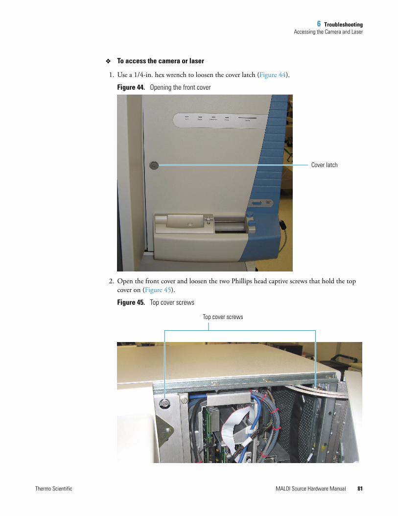
6 TroubleshootingAccessing the Camera and Laser
To access the camera or laser
1. Use a 1/4-in. hex wrench to loosen the cover latch (Figure 44).
Figure 44. Opening the front cover
2. Open the front cover and loosen the two Phillips head captive screws that hold the top cover on (Figure 45).
Figure 45. Top cover screws
Cover latch
Top cover screws
Thermo Scientific MALDI Source Hardware Manual 81
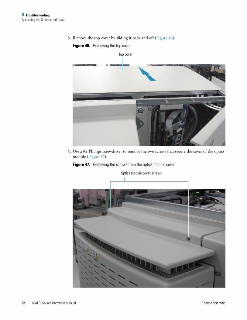
6 TroubleshootingAccessing the Camera and Laser
3. Remove the top cover by sliding it back and off (Figure 46).
Figure 46. Removing the top cover
4. Use a #2 Phillips screwdriver to remove the two screws that secure the cover of the optics module (Figure 47).
Figure 47. Removing the screws from the optics module cover
Top cover
Optics module cover screws
82 MALDI Source Hardware Manual Thermo Scientific

6 TroubleshootingAccessing the Camera and Laser
5. Remove the optics module cover (Figure 48).
6. Loosen the four captive screws that secure the RF shield.
Figure 48. RF shield screws
7. Remove the RF shield to access the laser and camera (Figure 49).
Figure 49. Camera and laser
RF shield screws
Camera
Laser
Thermo Scientific MALDI Source Hardware Manual 83

7
Replaceable Parts and Accessories
This chapter provides information about the replaceable parts, chemicals, and supplies for your LTQ XL MALDI source.
Replaceable PartsMALDI Vacuum Solenoid Assembly (P/N 97155-60088)
AccessoriesProteoMass™ MALDI Calibration kit available from Thermo Fisher Scientific (P/N HAZMAT-01-0033) or Sigma-Aldrich (P/N MSCAL4, call 1-800-325-5832).
Tissue Imaging Kit (P/N 97155-62124) containing tissue imaging slides, a software CD, an adapter for stainless steel slides, an adapter for glass slides, a base plate, a scanner, and a frame to hold the sample plate for scanning on the scanner.
Sample Plate Kit (P/N 97155-62033) which contains a 96- and 384-well sample plate, a general purpose blank plate, and a base plate.
API kit (P/N 97155-62123) which contains the additional parts required to convert a MALDI LTQ XL system to an LTQ XL API system.
MALDI Accessory Kit (P/N 97155-62025), which contains laser protective eye wear, tools, swabs, gloves, and other items
Contents
• Replaceable Parts,
• Accessories
Thermo Scientific MALDI Source Hardware Manual 85

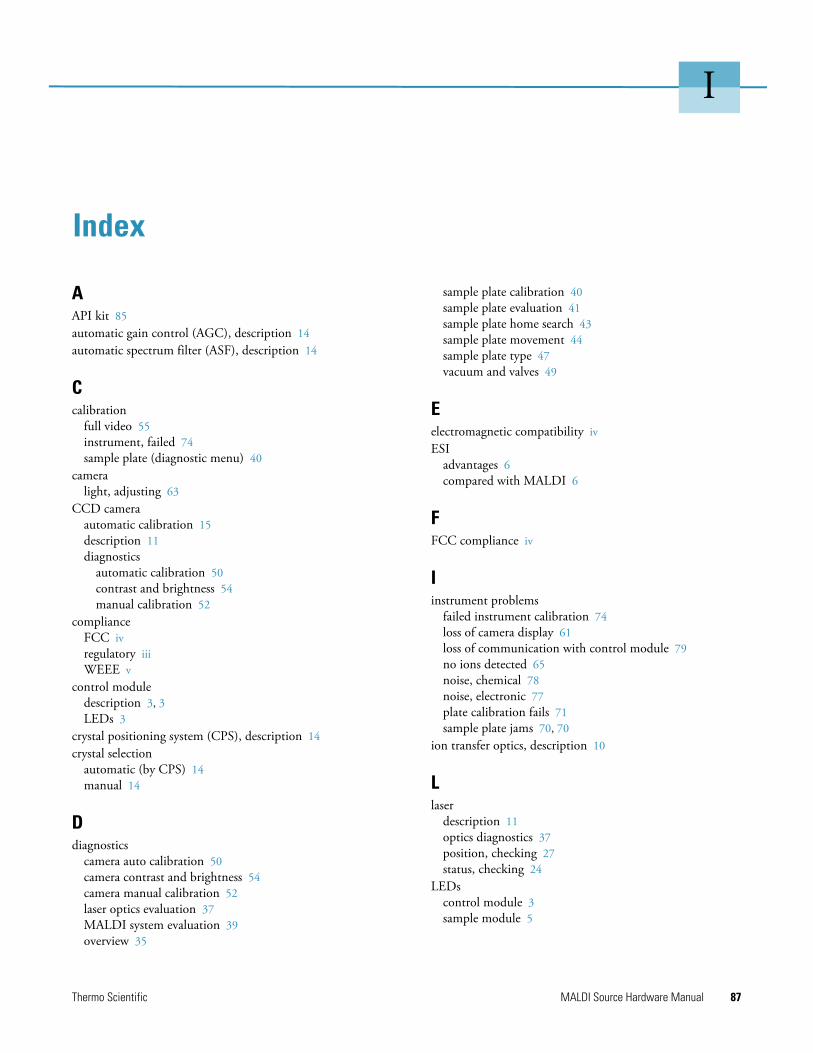
I
Index
AAPI kit 85automatic gain control (AGC), description 14automatic spectrum filter (ASF), description 14
Ccalibration
full video 55instrument, failed 74sample plate (diagnostic menu) 40
cameralight, adjusting 63
CCD cameraautomatic calibration 15description 11diagnostics
automatic calibration 50contrast and brightness 54manual calibration 52
complianceFCC ivregulatory iiiWEEE v
control moduledescription 3, 3LEDs 3
crystal positioning system (CPS), description 14crystal selection
automatic (by CPS) 14manual 14
Ddiagnostics
camera auto calibration 50camera contrast and brightness 54camera manual calibration 52laser optics evaluation 37MALDI system evaluation 39overview 35
sample plate calibration 40sample plate evaluation 41sample plate home search 43sample plate movement 44sample plate type 47vacuum and valves 49
Eelectromagnetic compatibility ivESI
advantages 6compared with MALDI 6
FFCC compliance iv
Iinstrument problems
failed instrument calibration 74loss of camera display 61loss of communication with control module 79no ions detected 65noise, chemical 78noise, electronic 77plate calibration fails 71sample plate jams 70, 70
ion transfer optics, description 10
Llaser
description 11optics diagnostics 37position, checking 27status, checking 24
LEDscontrol module 3sample module 5
Thermo Scientific MALDI Source Hardware Manual 87
Index: M
MMALDI
advantages 6compared with ESI 6
MALDI accessory kit 85MALDI source 3
main components 9optics module, description 4overview 1preparing for use 23sample module, description 5system diagnostics 39
microscans, guidelines for number of 20
Ooptics module, description 4
Ppressure levels, checking 23ProteoMass calibration kit 85
Rregulatory compliance iii
Ssafety standards iiisample module
description 5LEDs 5
sample plateautomatic calibration 15automatic recognition 14calibrating position 25calibration, checking 46description 15diagnostics
calibration 40evaluation 41home search 43movement 44plate type 47
failed calibration 71handling precautions 20jammed in instrument 70, 70loading 17operational guidelines 20positioning 10type, determining 47
Tthin-layer sample
preparation 55testing laser 65
tissue imaging kit 85
Vvacuum levels, checking 23vacuum system
checking pressure levels 23description 10diagnostics 49
vacuum valve, replacing 33
WWEEE compliance v
XXYZ mechanism
description 9testing 44
88 MALDI Source Hardware Manual Thermo Scientific