Cellulose Microltration Membranes High-Flux, Porous and ...
21
Page 1/21 High-Flux, Porous and Homogeneous PVDF/ Cellulose Microltration Membranes Lucca Malucelli ( [email protected] ) Universidade Positivo https://orcid.org/0000-0003-4161-540X Inbal Ozeri Technion Israel Institute of Technology Mailson Matos UFPR: Universidade Federal do Parana Washington Magalhães EMBRAPA Marco Aurélio Carvalho Filho Positivo University: Universidade Positivo Moris Eisen Technion Israel Institute of Technology Research Article Keywords: membrane ltration, nanocelulose, water treatment Posted Date: June 7th, 2021 DOI: https://doi.org/10.21203/rs.3.rs-487246/v1 License: This work is licensed under a Creative Commons Attribution 4.0 International License. Read Full License Version of Record: A version of this preprint was published at Cellulose on January 12th, 2022. See the published version at https://doi.org/10.1007/s10570-022-04422-y.
Transcript of Cellulose Microltration Membranes High-Flux, Porous and ...

Page 1/21
High-Flux, Porous and Homogeneous PVDF/Cellulose Micro�ltration MembranesLucca Malucelli ( [email protected] )
Universidade Positivo https://orcid.org/0000-0003-4161-540XInbal Ozeri
Technion Israel Institute of TechnologyMailson Matos
UFPR: Universidade Federal do ParanaWashington Magalhães
EMBRAPAMarco Aurélio Carvalho Filho
Positivo University: Universidade PositivoMoris Eisen
Technion Israel Institute of Technology
Research Article
Keywords: membrane �ltration, nanocelulose, water treatment
Posted Date: June 7th, 2021
DOI: https://doi.org/10.21203/rs.3.rs-487246/v1
License: This work is licensed under a Creative Commons Attribution 4.0 International License. Read Full License
Version of Record: A version of this preprint was published at Cellulose on January 12th, 2022. See thepublished version at https://doi.org/10.1007/s10570-022-04422-y.

Page 2/21
AbstractLow hydrophilicity of membranes is probably the biggest concern in membrane �ltration since itincreases the costs for water treatment. Conversely, application of hydrophilic biopolymers (such ascellulose) is limited because of its complex and crystalline structure. Enabling the widely use of the mostcommon biopolymer in nature is crucial to improve the performance of water treatment, especially interms of membrane sustainability. Here, we study the effect of cellulose dissolution in the synthesis ofhomogeneous PVDF/cellulose membranes. Although only partial dissolution was achieved for studiedsamples, adding cellulose to the membranes greatly improved their water �ux. Besides, the porousstructure obtained after partial solvent removal indicates the WF (and consequently the pore size) may betailored according to the membrane production method. Therefore, the homogeneous cellulosemicro�ltration membranes studied here may have potential for water treatment considering their high-water �ux and low complexity to produce.
1. IntroductionWater is considered a �nite resource essential for life that is distributed around earth. Nevertheless, 97%is represented by non-potable seawater and, from the remaining freshwater, most is entrapped as iceglaciers thus virtually inaccessible (Wang et al. 2017). This issue was even of more interest in Israel dueto the low availability of freshwater resources in this semi-arid country located in the middle east.Therefore, the water shortage along with the exponential population growth after Israel’s independenceturned essential for the technological development to ful�ll population demands. The �rst desalinationplant in the country was opened in the late 90s which, along with other reuse and preservation practices(wastewater treatment, water conservation, etc.), enabled Israel’s self-sustainability andcommercialization of water surplus to neighbor countries (Weinglass 2015; IMFA 2018).
The �rst milestone within water treatment technology was the development in the 60s of desalinationmembranes of different types from which derivatized cellulose ones (cellulose acetate) stood out,presenting over 90% salt rejection (Loeb & Sourirajan 1963; 1964). Over the years, new materials havebeen used to improve water treatment e�ciency even further and to overcome the limitations of celluloseacetate membranes, especially the pH stability and rejection (Voicu et al. 2015). One of these materials ispolyvinylidene �uoride (PVDF), which is considered an ideal polymer in water treatment for its improvedmechanical, chemical and thermal stability (Razzaghi et al. 2014).
Nevertheless, the hydrophobic behavior of neat PVDF results in membranes with low water �ux andrejection, which affects membrane e�ciency in industrial scale. One alternative to overcome thesedrawbacks without compromising their stability is to mix PVDF with more hydrophilic materials, such asnanocellulose (Bai et al. 2012; Lalia et al. 2014; Lv et al. 2018; Zhang et al. 2017). However, none of thesemethods could accomplish cellulose dissolution when used along with other polymers; yet these wereonly able to disperse the cellulose within the membranes. This is due to its complex and crystalline

Page 3/21
structure that makes it insoluble in most organic solvents (Hu, et al. 2018; Ishii et al. 2008; Zhang et al.2014).
From the most common dissolution methods, the non-aqueous ones seem to be the most appropriatebecause water hinders the synthesis of PVDF membranes (Xiong et al. 2014; Xuet al. 2013). The well-studied LiCl/DMAc dissolution method can be a good alternative since it was reported to generate stabledissolved cellulose solutions for over an year (Dupont 2003). It consists in the heat activation of celluloseto allow �bers swelling in DMAc, followed by the interaction of LiCl between cellulose hydroxyl groups,thus leading to its dissolution (Ishii et al. 2008; Zhang et al. 2014).
Here, the effect of nanocellulose in PVDF membranes water �ux is studied. To the best of our knowledge,no other study attempted to dissolve nanocellulose for water treatment membranes. ThePVDF/nanocellulose porous membranes were prepared through partial solvent evaporation, followed byphase-inversion, using different types of cellulose (pristine, cellulose nanocrystals and cellulosenano�bers). The performance of the membranes was evaluated according to their water �ux and theirstructure was characterized by SEM.
2. Material And Methods2.1 MATERIAL
Bleached Eucalyptus Pulp (BEP) (obtained from Suzano Papel e Celulose, Brazil) was used as rawmaterial to prepare the cellulose nanocrystals (CNC) by acid hydrolysis and the nano�bers (CNF) byde�brillation. Microcrystalline cellulose (Avicel, PH 101) was acquired from Sigma-Aldrich (Saint-Louis,USA) and used without modi�cation as a blank. Polyvinylidene �uoride (PVDF), with an averagemolecular weight of 500,000, and the N, N-dimethylacetamide (DMAc) (38840, lot BCBW9878) were alsoacquired from Sigma-Aldrich.
2.2 METHODS
2.2.1 Preparation of cellulose nano�bers (CNF) and nanocrystals (CNC)
Based on the method described in Morais et al. (2013), BEP CNC and Avicel CNC were produced withminor modi�cations, as follow. Both sources (Avicel and BEP) were added into H2SO4 (60% m/m) at 1:20(w/v) and stirred at 45 ºC for 30 min. Then, the solids were washed thoroughly with distilled water and�ltered to remove residual acids and dissolved sugars. The solids were resuspended in water andsonicated in a Sonics (Sonics & Materials, inc.) Vibra-Cell VCX 130 (Newtown, USA) at an 80 % powerinput for 10 min to disperse cellulose aggregates. The colloidal suspensions were dialyzed in tap water toneutral pH for at least 5 days using D9527-100 ft. dialysis tubing membranes from Sigma-Aldrich (St.Louis, USA). To produce the CNF, BEP was soaked at 1% in 2 L distilled water, dispersed using a lab mixerand ground in a MKCA 6-2J super mass colloider, Masuko Sangyo (Kawaguchi, Japan) for 3 cycles.

Page 4/21
The colloidal suspensions (Avicel CNC, BEP CNC and BEP CNF) were spray-dried in an Elettronica VenetaMDS/EV spray-dryer (Motta di Livenza, Italy). This step was necessary since LiCl/DMAc-assisteddissolution of cellulose is sensitive to the presence of water and to avoid aggregation of nanocrystals.The procedure for producing both CNC and CNF is represented in Fig. 1.
2.2.3 X-ray diffractometry (XRD)
The X-ray diffractogram patterns were obtained in an X-ray Diffractometer X XRD 700 (Shimadzu, Japan)using Cu-Ka radiation (k = 1.5418 A°), 40 kV and 20 mA. The scattered radiation was detected in theangular range of 5-40º (2q), with a scanning speed of 2º min-1 (2q) and a step of 0.02º (2q). Segalcrystallinity index was calculated according to Eq. (1) (Segal et al. 1959):
where I200 refers to the maximum intensity due to re�ections of the planes (200) around 23º and Iam to
the amorphous contribution, at the minimum intensity between 15o<2q <23o (at approximately 18º (2q))(French and Santiago Cintrón 2013). Prior to the crystallinity index calculation, the diffractograms weresmoothed in the software OriginPro 8, using the Savitzky–Golay method (50 points) and a second orderpolynomial function. The baseline correction was performed by subtracting a straight line between thepoints of least intensity in the range of 2 q of 5° and 40°, as previously proposed by Agarwal et al. (2018).
2.2.4 Cellulose dissolution
All cellulose samples (Avicel, Avicel CNC, BEP CNC and BEP CNF) and LiCl were previously dried at 70 ºCin a JSR JSVO-60 T vacuum oven (Gongju city, South Korea) for at least 24 h to remove residualmoisture, which could affect the dissolution e�ciency. The dissolution method was based on Hu et al.(2018) and Ishii et al. (2008), using the cellulose to DMAc/LiCl ratio (w/w) of 3/97. First, each of the driedcellulose samples was mixed with DMAc, heated to 150 ºC and stirred for 1 h. Heating the DMAc justbelow its boiling point is crucial for cellulose activation and consequent dissolution since it allows thepenetration of the solvent and swelling of the �bers (Dupont 2003). Next, the temperature was decreasedto 100 ºC and LiCl was added to the system. The amount of LiCl was that necessary to reach 8 wt% LiClin DMAc. After complete dissolution of the salt (at least 30 min stirring), the temperature was decreasedto 50 ºC and the solution was stirred for at least 16 h. Afterwards, the solution was let to stand at roomtemperature for 24 h and the cellulose was considered dissolved if the �nal solution became clear.
2.2.5 Synthesis of PVDF membranes
The membranes were produced by Sourirajan-Loeb method (a.k.a. phase inversion) (Loeb and Sourirajan1963) with the modi�cations as follow. PVDF and different amounts of each dissolved cellulose source(Avicel, Avicel CNC, BEP CNC or BEP CNF) were added to reach the �nal concentration of cellulose intothe casting solution of 1%. During preliminary studies, it was decided to use a polymer to solvent ratio of

Page 5/21
15:85 (m/m) since higher amounts of polymers could lead to high viscosity gels, which hindered thepouring and casting to make the membranes. The PVDF powder was added into DMAc, heated to 60 ºCand stirred at 200 rpm until completely dissolved. Only then, the dissolved cellulose (in DMAc) was addedto the casting solution and stirred until obtaining a homogeneous solution. The importance of dissolutionon the membranes properties was also checked by using the same cellulose sources. For this, eachcellulose source (in powder) was directly mixed with PVDF dissolved in DMAc to make PVDF/celluloseblends without the cellulose pre-dissolution step.
To prepare the membranes, around 1.5 mL of each casting solution (PVDF, DMAc anddispersed/dissolved cellulose) was poured onto individual glass plates and smeared using a Sheen1107/80/1 casting knife (Ho Chi Minh, Vietnam) at a 120 mm gap size between the plate and the knife.The casted membranes were then immersed into a distilled water bath (around 20 ºC) to allow theremaining solvent (DMAc) migration to water. Partial solvent evaporation in�uence on the membraneproperties and structure was also investigated in additional trials as it can induce the formation ofsponge-like pores rather than �nger-like structures by reducing solvent-nonsolvent exchange (Guillen et al.2011). Therefore, the casted solutions were previously heated in a vacuum oven drier (National ApplianceCo. USA) at 75 ºC until dry (around 11 min). The relative humidity (RH) was recorded during the tests andit ranged from 10-15 %. Then, the membranes were immersed in distilled water, as usual, and thedetached membranes (with or without partial solvent evaporation) were washed under �owing distilledwater and kept immersed in distilled water �lled �asks until further analysis.
2.2.6 Scanning electron microscopy (SEM)
The SEM analyzes were performed using a TESCAN Vega-II (Brno, Czech Republic) equipment which wascon�gured with 20 mm reading scale and 10 kV tension. For surface analysis, small pieces of themembranes were cut and clued on carbon tape. For cross-section, small pieces of the membranes werefrozen and snapped in liquid nitrogen and supported in SEM stubs using a G 302 PLANO GmbH quick-drying conductive silver glue (Wetzlar, Germany). Then, the samples were metalized with gold andanalyzed in an electron detector.
2.2.7 Water �ux (WF)
The e�ciency of membranes according to their water �ux was measured using the dead-end �ltrationsystem represented in Bussi et al. (2018). Brie�y, distilled water was added to system and the membraneswere maintained under water at a constant pressure (3 bar) for at least 2 h to reach their equilibrium.Then, the membranes WF was measured from 1 to 10 bar. The measurements were conducted intriplicate for each type of membrane.
2.2.8 Statistical analysis
For statistical analysis, analysis of variance (ANOVA) and Tukey’s test were employed to comparesamples average at a 95% con�dence level (p < 0.05) using Statistica 13.3 software (StatSoft, Inc, Tulsa,

Page 6/21
OK, USA).
3. Results And Discussion3.1 XRD
As expected, the partial removal of the amorphous portion from cellulose increased the crystallinity indexof BEP CNC (~88%) compared to BEP CNF (~79%) (Fig. 2). The higher crystallinity index of Avicel CNC(~90%) compared to BEP CNC (88%) is due to the higher purity of Avicel (in terms of cellulose content)since it consists in pure cellulose rather than a mix of cellulose and hemicellulose in BEP (Malucelli et al.2018).
3.2 Cellulose dissolution
Cellulose is usually dissolved using the LiCl/DMAc system in concentrations up to 3%, even for highmolecular weight cellulose (Hu et al. 2018; Jing et al. 2007). However, the molecular weight of wood pulptends to be much higher than pure cellulose. Therefore, complete dissolution is only achieved by reducingthe cellulose and LiCl/DMAc ratio. In earlier studies, Sjöholm et al. (2000) could only dissolve bleachedand unbleached wood pulp using much lower amounts of sample (around 0.5% bleached wood pulp intotal solution). Consequently, BEP CNF was only partially dissolved using this same ratio (0.5/ 99.5cellulose/LiCl and DMAc) since higher cellulose content resulted in cellulose agglomerates and a viscoushazy solution. The minimum amounts of cellulose (in respect of its source), LiCl, DMAc and their ratioused in the partial dissolution tests are represented in Table 1.
Table 1 – Required concentration of cellulose from different sources, LiCl and DMAc to ensure its partialdissolution.
Sample Cellulose % (m/m) LiCl % (m/m) DMAc % (m/m) Cellulose to LiCl/DMAc ratio
Avicel 3 8 89 3/97
Avicel CNC 2 8 90 2/98
BEP CNC 2 8 90 2/98
BEP CNF 0.5 8 91.5 0.5/99.5
BEP – bleached eucalyptus pulp; CNC – cellulose nanocrystals; CNF – cellulose nano�bers.
These results suggest that the size and composition of the �bers have a higher in�uence than thecrystallinity index towards cellulose dissolution (Isogai and Atalla 1998). Although the in�uence ofcellulose crystallinity in dissolution is a controversial aspect (Parviainen et al. 2014; Ramos et al. 2011), itappears that dissolution is only complete if decrystallization and disentanglement are combined(Ghasemi et al. 2017). BEP CNF have a much more complex structure than their respective nanocrystals(BEP CNC – after acid hydrolysis) since it is basically composed of interchained cellulose and around

Page 7/21
15% hemicellulose (Malucelli et al. 2018). Therefore, the lower availability of cellulose and the higherdegree of polymerization in BEP CNF (as suggested by its apparent high viscosity) explains their lowdissolution ability (only 0.5% cellulose in total solution). On the other hand, dissolution was facilitatedusing cellulose with low degree of polymerization (such as Avicel) or after acid hydrolysis (Avicel CNC orBEP CNC). The removal of amorphous domains by acid hydrolysis probably improved the susceptibilityof cellulose for dissolution (Lu and Hsieh 2010).
3.3 Membranes preparation
Because of the low dissolution ability of BEP CNF, it was not possible to make 1% BEP CNF membraneswhile maintaining DMAc, PVDF and LiCl concentrations constant (the maximum concentration possiblewas 0.25% BEP CNF in total solution). Therefore, it was decided not to include these membranes in thewater �ux and surface/ cross-section characterization studies. The amount of each component used toproduce the membranes is shown in Table 2.
Table 2 – Procedure to prepare the PVDF and cellulose (Avicel, Avicel CNC and BEP CNC) membraneswith or without partial solvent evaporation.
Membranes PVDF%
DMAc%
Dispersedcellulose %
Dissolvedcellulose %
Solventevaporation?
PVDF/ celluloseblends
15 75 10 - No
Blank PVDF 15 85 - - No
PVDF + cellulose 15 84 - 1 No
Blank PVDF 15 85 - - Yes
PVDF + cellulose 15 84 - 1 Yes
BEP – bleached eucalyptus pulp; CNC – cellulose nanocrystals.
The visual aspect of the membranes was similar despite the partial solvent evaporation used for some ofthe samples. It was interesting to observe that the surface of the membranes was very homogeneouseven for those containing partially dissolved cellulose. In preliminary studies using dispersed cellulose(rather than dissolved cellulose), the PVDF membranes were very heterogeneous with several surfacemicropores (showing low mechanical strength) and variable thickness. These results corroborate withthose obtained by Lv et al. (2018) in which large CNC agglomerates resulted in several pores/ defectsspecially on the membranes’ surface. To overcome the limitations in using dispersed cellulosemembranes (PVDF/ cellulose blends), a deeper investigation on PVDF + dissolved cellulose membraneswas conducted in this study since this is a much more homogeneous system (and scalable, in terms ofreproducibility) than the �rst.
3.4 Scanning electron microscopy (SEM)

Page 8/21
All PVDF/ cellulose blends had a heterogeneous surface aspect, because of the low compatibilitybetween cellulose (hydrophilic) and PVDF (hydrophobic) (Figs. 3-5). The addition of cellulose resulted notonly in the formation of agglomerates on blends surface but also in the thickness increase of themembranes. However, this did not compromise the WF probably because the addition of celluloseimproved the hydrophilicity of the PVDF membranes (Lv et al. 2018).
Although it was di�cult to determine the actual size and extension of the membranes surface pores,however, it was clear that the immersion precipitation technique resulted in the formation of verticalchannels. This kind of membranes present lower mechanical strength because of the “�nger-like”structures formed during the quick solvent exchange after immersion in a coagulation bath (distilledwater) (Lv et al. 2018).
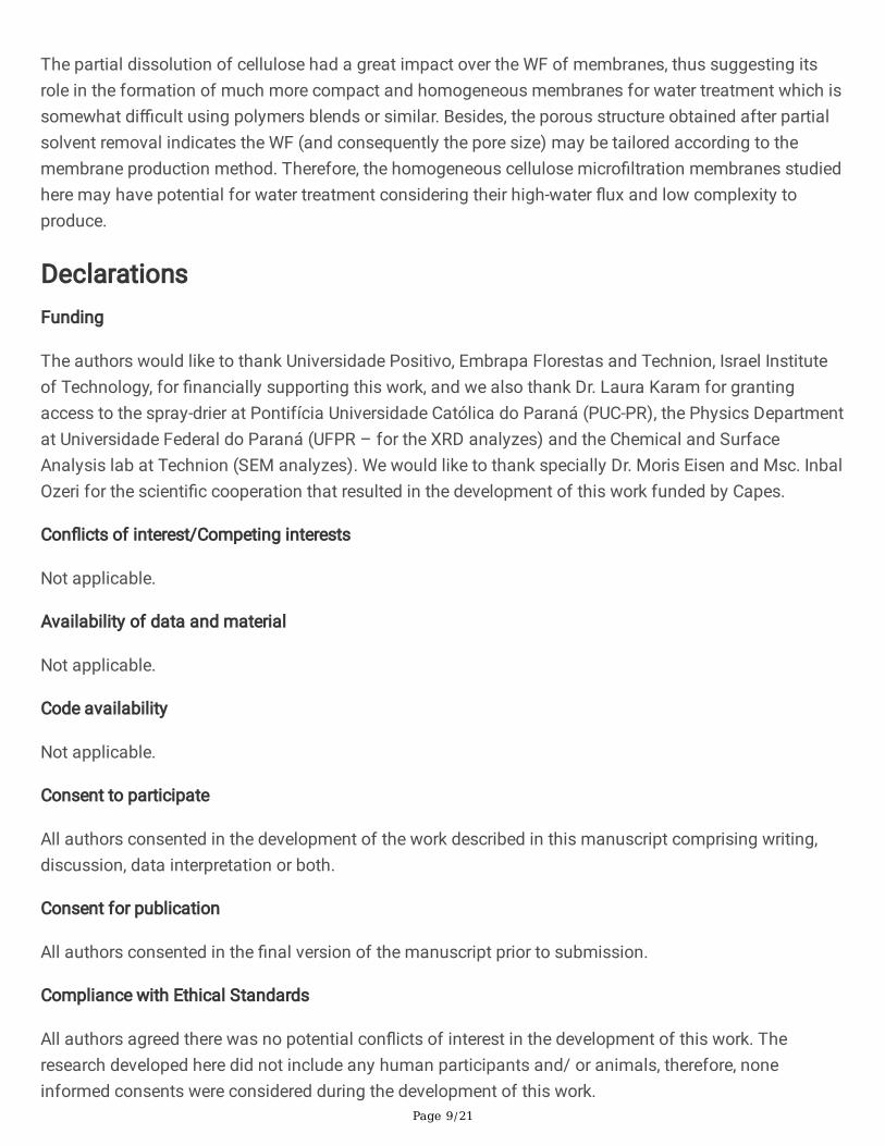
After cellulose partial dissolution and solvent evaporation (DMAc), the membranes structure drasticallychanged. This was con�rmed by the formation of dense membranes (Figs. 6-8), yet with a clear surface(due to complete cellulose dissolution), in contrast to the PVDF/ cellulose blends (Figs. 3-5). Besides,solvent evaporation created several surface pores (Kim et al. 2016) ranging from 300-400 nm (indiameter) that probably contributed to the high WF and, therefore, suggesting the formation ofmicro�ltration membranes (Hankins and Singh 2016).
3.5 WF
The PVDF and cellulose blends (dispersed cellulose) had similar WF to other studies that used mainlycellulose nanocrystals to improve the hydrophilicity of PVDF membranes (Bai et al. 2012; Lalia et al.2014; Lv et al. 2018). The use of cellulose greatly increased the WF of the membranes, especially in thatusing pure cellulose (Avicel + PVDF), suggesting an increase in their hydrophilicity (Fig. 9). Also, the useof both partially dissolved nanocellulose sources (Avicel CNC and BEP CNC) resulted in a much morecompact membrane as suggested by their lower WF (compared to PVDF + Avicel).
Next, it was decided to evaluate the in�uence of cellulose dissolution (Fig. 10) and partial solventevaporation (Fig. 11) on the membranes WF. An intense decrease on membranes’ WF was observed aftercellulose dissolution, suggesting the formation of a much more homogeneous membrane (compared toPVDF and cellulose blends) and free of agglomerates and large pores derived from cellulose particles.
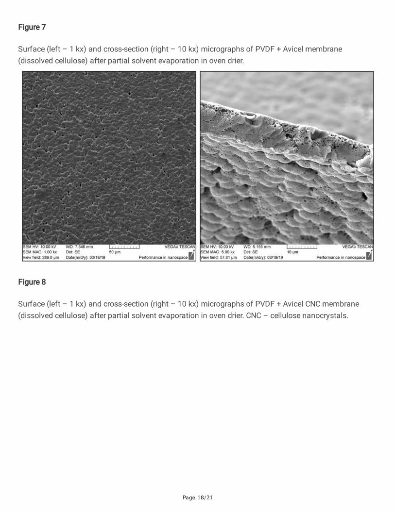
The partial solvent removal is capable of modifying the pore pattern in membranes by forming porousstructures rather than “�nger-like” voids and smaller surface pores (Guillen et al. 2011). Therefore, it isclear that the thermal pretreatment and cellulose dissolution contributed to generating porous andhomogeneous high-�ux membranes (Fig. 11) that could be a potential method to produce micro�ltrationmembranes, considering these have in general WF over 500 L/m2h (Han et al. 2016; Meng et al. 2018; Muet al. 2010).
4. Conclusion
Page 9/21
The partial dissolution of cellulose had a great impact over the WF of membranes, thus suggesting itsrole in the formation of much more compact and homogeneous membranes for water treatment which issomewhat di�cult using polymers blends or similar. Besides, the porous structure obtained after partialsolvent removal indicates the WF (and consequently the pore size) may be tailored according to themembrane production method. Therefore, the homogeneous cellulose micro�ltration membranes studiedhere may have potential for water treatment considering their high-water �ux and low complexity toproduce.
DeclarationsFunding
The authors would like to thank Universidade Positivo, Embrapa Florestas and Technion, Israel Instituteof Technology, for �nancially supporting this work, and we also thank Dr. Laura Karam for grantingaccess to the spray-drier at Pontifícia Universidade Católica do Paraná (PUC-PR), the Physics Departmentat Universidade Federal do Paraná (UFPR – for the XRD analyzes) and the Chemical and SurfaceAnalysis lab at Technion (SEM analyzes). We would like to thank specially Dr. Moris Eisen and Msc. InbalOzeri for the scienti�c cooperation that resulted in the development of this work funded by Capes.
Con�icts of interest/Competing interests
Not applicable.
Availability of data and material
Not applicable.
Code availability
Not applicable.
Consent to participate
All authors consented in the development of the work described in this manuscript comprising writing,discussion, data interpretation or both.
Consent for publication
All authors consented in the �nal version of the manuscript prior to submission.
Compliance with Ethical Standards
All authors agreed there was no potential con�icts of interest in the development of this work. Theresearch developed here did not include any human participants and/ or animals, therefore, noneinformed consents were considered during the development of this work.

Page 10/21
ReferencesAgarwal UP, Ralph SA, Reiner RS, Baez C (2018) New cellulose crystallinity estimation method thatdifferentiates between organized and crystalline phases. Carbohydr Polym, 190(February), 262–270.https://doi.org/10.1016/j.carbpol.2018.03.003
Bai H, Wang X, Zhou Y, Zhang L (2012) Preparation and characterization of poly(vinylidene �uoride)composite membranes blended with nano-crystalline cellulose. Pro. Nat Sci: Mat Int, 22(3), 250–257.https://doi.org/10.1016/j.pnsc.2012.04.011
Bussi Y, Golan S, Dosoretz CG, Eisen MS (2018) Synthesis, characterization and performance ofpolystyrene/PMMA blend membranes for potential water treatment. Desalination, 431(December 2017),35–46. https://doi.org/10.1016/j.desal.2017.12.024
Dupont AL (2003) Cellulose in lithium chloride/N,N-dimethylacetamide, optimisation of a dissolutionmethod using paper substrates and stability of the solutions. Polymer, 44(15), 4117–4126.https://doi.org/10.1016/S0032-3861(03)00398-7
French AD, Santiago Cintrón M (2013) Cellulose polymorphy, crystallite size, and the Segal CrystallinityIndex. Cellulose, 20(1), 583–588. https://doi.org/10.1007/s10570-012-9833-y
Ghasemi M, Tsianou M, Alexandridis P (2017) Assessment of solvents for cellulose dissolution. BioresourTechnol, 228(December), 330–338. https://doi.org/10.1016/j.biortech.2016.12.049
Guillen GR, Pan Y, Li M, Hoek EMV (2011) Preparation and characterization of membranes formed bynonsolvent induced phase separation: A review. Ind Eng Chem Res, 50(7), 3798–3817.https://doi.org/10.1021/ie101928r
Han Y, Song S, Lu Y, Zhu D (2016) Applied Surface Science A method to modify PVDF micro�ltrationmembrane via ATRP with low-temperature plasma pretreatment. App Surf Sci, 379, 474–479.https://doi.org/10.1016/j.apsusc.2016.04.114
Hankins NP, Singh R (2016) Emerging Membrane Technology for Sustainable Water Treatment. EmergingMembrane Technology for Sustainable Water Treatment. https://doi.org/10.1016/C2012-0-07949-5
Hu Y, Thalangamaarachchige VD, Acharya S, Abidi N (2018) Role of low-concentration acetic acid inpromoting cellulose dissolution. Cellulose, 25(8), 4389–4405. https://doi.org/10.1007/s10570-018-1863-7
Ishii D, Tatsumi D, Matsumoto T (2008) Effect of solvent exchange on the supramolecular structure, themolecular mobility and the dissolution behavior of cellulose in LiCl/DMAc. Carbohydr Res, 343(5), 919–928. https://doi.org/10.1016/j.carres.2008.01.035

Page 11/21
Isogai A, Atalla RH (1998) Dissolution of cellulose in aqueous NaOH solutions. Cellulose, 5(4), 309–319.https://doi.org/10.1023/A:1009272632367
Jing H, Zhu L, Hua-yang L, Guo-hua W, Jun-wen P (2007) Solubility of wood-cellulose in LiCl / DMACsolvent system. For Stud China, 9(3), 217–220. https://doi.org/10.1007/s11632-007-0035-x
Kim JF, Jung JT, Wang HH, Suk Y, Moore T, Sanguineti A, Drioli E, Lee YM (2016) Microporous PVDFmembranes via thermally induced phase separation (TIPS) and stretching methods. J Memb Sci, 509,94–104. https://doi.org/10.1016/j.memsci.2016.02.050
Lalia BS, Guillen E, Arafat HA, Hashaikeh R (2014) Nanocrystalline cellulose reinforced PVDF-HFPmembranes for membrane distillation application. Desalination, 332(1), 134–141.https://doi.org/10.1016/j.desal.2013.10.030
Loeb S, Sourirajan S (1963) Sea Water Demineralization by Means of an Osmotic Membrane. In AdvChem (Saline Water Conversion-II) (Vol. 38, pp. 117–132). https://doi.org/10.1021/ba-1963-0038.ch009
Loeb S, Sourirajan S (1964) 3113132. USA: Washington, DC: U.S. Patent and Trademark O�ce.
Lu P, Hsieh YL (2010) Preparation and properties of cellulose nanocrystals: Rods, spheres, and network.Carbohydr Polym, 82(2), 329–336. https://doi.org/10.1016/j.carbpol.2010.04.073
Lv J, Zhang G, Zhang H, Zhao C, Yang F (2018) Improvement of antifouling performances for modi�edPVDF ultra�ltration membrane with hydrophilic cellulose nanocrystal. App Surf Sci, 440, 1091–1100.https://doi.org/https://doi.org/10.1016/j.apsusc.2018.01.256
Malucelli LC, Matos M, Jordão C, Lomonaco D, Lacerda LG, Carvalho Filho MAS, Magalhães WLE (2018)In�uence of cellulose chemical pretreatment on energy consumption and viscosity of produced cellulosenano�bers (CNF) and mechanical properties of nanopaper. Cellulose, 0. https://doi.org/10.1007/s10570-018-2161-0
Meng FN, Zhang MQ, Ding K, Zhang T, Gong YK (2018) Cell membrane mimetic PVDF micro�ltrationmembrane with enhanced antifouling and separation performance for oil/water mixtures. J Mat Chem A,6(7), 3231–3241. https://doi.org/10.1039/C7TA10135J
Morais JPS, Rosa MDF, De Souza Filho MDSM, Nascimento LD, Do Nascimento, DM, Cassales AR (2013)Extraction and characterization of nanocellulose structures from raw cotton linter. Carbohydr Polym,91(1), 229–235. https://doi.org/10.1016/j.carbpol.2012.08.010
Mu C, Su Y, Sun M, Chen W, Jiang Z (2010) Remarkable improvement of the performance of poly (vinylidene �uoride ) micro�ltration membranes by the additive of cellulose acetate. J Memb Sci, 350,293–300. https://doi.org/10.1016/j.memsci.2010.01.004

Page 12/21
Parviainen H, Parviainen A, Virtanen T, Kilpeläinen I, Ahvenainen P, Serimaa R, Grönqvist S, Maloney T,Maunu SL (2014) Dissolution enthalpies of cellulose in ionic liquids. Carbohydr Polym, 113, 67–76.https://doi.org/https://doi.org/10.1016/j.carbpol.2014.07.001
Ramos LA, Morgado DL, Gessner F, Frollini E, El Seoudb OA (2011) A physical organic chemistryapproach to dissolution of cellulose: Effects of cellulose mercerization on its properties and on thekinetics of its decrystallization. Arkivoc, 2011(7), 416–425.https://doi.org/10.3998/ark.5550190.0012.734
Razzaghi MH, Safekordi A, Tavakolmoghadam M, Rekabdar F, Hemmati M (2014) Morphological andseparation performance study of PVDF/CA blend membranes. J Memb Sci, 470, 547–557.https://doi.org/10.1016/j.memsci.2014.07.026
Sjöholm E, Gustafsson K, Eriksson B, Brown W, Colmsjo A (2000) Aggregation of cellulose in lithiumchloride / N , N-dimethylacetamide Aggregation of cellulose in lithium chloride / N , N -dimethylacetamide. Carbohydr Polym, 8617(February 2018). https://doi.org/10.1016/S0144-8617(99)00080-6
Voicu SI, Muhulet A, Antoniac I, Corobea MS (2015) Cellulose Derivatives Based Membranes forBiomedical Applications. Key Eng Mat, 638, 27–30.https://doi.org/10.4028/www.scienti�c.net/KEM.638.27
Wang K, Abdalla AA, Khaleel MA, Hilal N, Khraisheh MK (2017) Mechanical properties of waterdesalination and wastewater treatment membranes. Desalination, 401, 190–205.https://doi.org/10.1016/j.desal.2016.06.032
Xiong B, Zhao P, Hu K, Zhang L, Cheng G (2014) Dissolution of cellulose in aqueous NaOH/urea solution:Role of urea. Cellulose, 21(3), 1183–1192. https://doi.org/10.1007/s10570-014-0221-7
Xu A, Zhang Y, Zhao Y, Wang J (2013) Cellulose dissolution at ambient temperature: Role of preferentialsolvation of cations of ionic liquids by a cosolvent. Carbohydr Polym, 92(1), 540–544.https://doi.org/10.1016/j.carbpol.2012.09.028
Zhang C, Liu R, Xiang J, Kang H, Liu Z, Huang Y (2014) Dissolution mechanism of cellulose in N,N-dimethylacetamide/lithium chloride: Revisiting through molecular interactions. J Phys Chem B, 118(31),9507–9514. https://doi.org/10.1021/jp506013c
Zhang X, Zheng S, Zou H, Zheng X, Liu Z, Yang W, Yang M (2017) Two-step positive temperaturecoe�cient effect with favorable reproducibility achieved by speci�c “island-bridge” electrical conductivenetworks in HDPE/PVDF/CNF composite. Composites Part A: App Sci Manuf, 94, 21–31.https://doi.org/10.1016/j.compositesa.2016.12.001
Figures

Page 13/21
Figure 1
Steps for the preparation of spray-dried Avicel and BEP CNC and BEP CNF. BEP – bleached eucalyptuspulp; CNC – cellulose nanocrystals; CNF – cellulose nano�bers.

Page 14/21
Figure 2
XRD patterns and crystallinity index of cellulose from different sources. Averages followed by the sameletters do not differ statistically by Tukey’s test (p < 0.05).

Page 15/21
Figure 3
Surface (left – 1 kx) and cross-section (right – 10 kx) micrographs of Blank PVDF membrane.
Figure 4

Page 16/21
Surface (left – 1 kx) and cross-section (right – 10 kx) micrographs of PVDF + Avicel membrane(dispersed cellulose).
Figure 5
Surface (left – 1 kx) and cross-section (right – 10 kx) micrographs of PVDF + Avicel CNC membrane(dispersed cellulose). CNC – cellulose nanocrystals.

Page 17/21
Figure 6
Surface (left – 1 kx) and cross-section (right – 10 kx) micrographs of Blank PVDF membrane after partialsolvent evaporation in oven drier.
Page 18/21
Figure 7
Surface (left – 1 kx) and cross-section (right – 10 kx) micrographs of PVDF + Avicel membrane(dissolved cellulose) after partial solvent evaporation in oven drier.
Figure 8
Surface (left – 1 kx) and cross-section (right – 10 kx) micrographs of PVDF + Avicel CNC membrane(dissolved cellulose) after partial solvent evaporation in oven drier. CNC – cellulose nanocrystals.

Page 19/21
Figure 9
Effect of pressure on the water �ux of PVDF and dispersed cellulose blends. CNC – cellulosenanocrystals; BEP – bleached eucalyptus pulp.

Page 20/21
Figure 10
Effect of pressure on the water �ux of PVDF and dissolved cellulose membranes. CNC – cellulosenanocrystals; BEP – bleached eucalyptus pulp.
Page 21/21
Figure 11
Effect of pressure on the water �ux of PVDF and dissolved cellulose membranes (after partial solventevaporation). CNC – cellulose nanocrystals; BEP – bleached eucalyptus pulp.