VTT Science 162: Flexible pigment-cellulose nanofibril ... · PDF fileFlexible...
129
• V I S I O N S • S C I E N C E • T E C H N O L O G Y • R E S E A R C H H I G H L I G H T S n o i t a t r e s s i D 2 6 1 e s o l u l l e c - t n e m g i p e l b i x e l F s e t i s o p m o c l i r b fi o n a n s c i n o r t c e l e d e t n i r p r o f s n o i t a c i l p p a n e n i v r o T a n i i r a t a K
-
Upload
nguyenduong -
Category
Documents
-
view
217 -
download
1
Transcript of VTT Science 162: Flexible pigment-cellulose nanofibril ... · PDF fileFlexible...
setisopmoc lirbfionan esolullec-tnemgip elbixelF snoitacilppa scinortcele detnirp rof
nenivroT aniirataK
,elbixefl fo noitcudorp eht rof deen gniworg a syadawon si erehT detnirp rof setartsbus yldneirf yllatnemnorivne dna ,evitceffe-tsoc
sa )FNMC( slirbfionan dna-orcim esolulleC .snoitacilppa scinortcele mia ehT .dlefi siht ni tseretni tnacfiingis detcartta sah lairetam war a
fo esu levon fo seitilibissop eht dnapxe ot saw krow siht fo .setisopmoc desab-oib rof )FNMC( slirbfionan dna -orcim esolullec stnemgip cinagroni enibmoc ot saw krow siht ni hcaorppa wen ehT
snoitanibmoc tnenopmoc fo egnar ediw ylevitaler a ni FNMC dna lirbfionan dna -orcim esolullec - tnemgip fo noitareneg eht rof
eht gniyfiralc no saw krow eht fo sucof niam ehT .setisopmoc etisopmoc eht dna desu slairetam war eht neewteb pihsnoitaler
dna ssenhtooms sa hcus ,tcudorp lanfi eht fo seitreporp larutcurts noitartlfi muucav yb derutcafunam erew setisopmoc ehT .ytisorop
htob ni ,elacs tolip-imes ni gnitsac mlfi yb dna elacs yrotarobal ni .gnirednelac dna ,gniyrd ,gnisserp tew yb dewollof sesac
sa derutcafunam erew secived lanoitcnuf tnereffid ,krow siht nI eht fo ytilibasu eht etartsnomed ot serutcurts tpecnoc-fo-foorp ehT .snoitacilppa scinortcele detnirp rof setisopmoc depoleved
-tnemgip suoroponan a evah setisopmoc FNMCP depolevednoitprosba kni dellortnoc swolla taht erutcurts krowten FNMC
ssenhtooms dna ytisorop etartsbus deriuqer ehT .seitreporp dna ,tnevlos ,kni ,dohtem gnitnirp desu eht no dneped ylgnorts
elbaniatsus a reffo setisopmoc FNMCP ehT .ngised ecived hgih ta desu eb ot snoitacilppa scinortcele detnirp rof etartsbus
yltnerruc nac smlfi citsalp laiceps yrev ylno taht serutarepmet .dnatshtiw
NBSI 7-1758-83-159-879 ).de kcab tfoS( NBSI 0-0758-83-159-879 :LRU( snoitacilbup/tcapmi/moc.hcraeserttv.www//:ptth )
X911-2422 L-NSSI X911-2422 NSSI )tnirP( 3021-2422 NSSI )enilnO(
:NBSI:NRU/fi.nru//:ptth 0-0758-83-159-879
E
CN
EIC
S T
TV
26
1 .
..r
of s
etis
op
mo
c li
rbi
fo
na
n es
olul
le
c-t
ne
mgi
p el
bix
elF
•VIS
ION
S•SCIENCE•TEC
HN
OL
OG
Y•RESEARCHHIGHLI
GH
TS
noitatressiD
261
esolullec-tnemgip elbixelF setisopmoc lirbfionanscinortcele detnirp rof
snoitacilppa
nenivroT aniirataK
TTV ECNEICS 261
esolullec-tnemgip elbixelF setisopmoc lirbfionan
scinortcele detnirp rof snoitacilppa
nenivroT aniirataK
dtL dnalniF fo ertneC hcraeseR lacinhceT TTV
noitatressid larotcoD
gnitrevnoC dna gnitaoC repaP fo yrotarobaL
slairetaM lanoitcnuF rof retneC
gnireenignE dna ecneicS fo ytlucaF
ytisrevinU imedakA obÅ
7102 ,dnalniF ,obÅ
eb ot )ygolonhceT( ecneicS fo rotcoD fo eerged eht rof sisehT
ni msicitirc dna noitanimaxe cilbup rof noissimrep eud htiw detneserp
00.21 ta 7102 rebotcO fo ht72 eht no imedakA obÅ ta ukruT
NBSI 7-1758-83-159-879 ).de kcab tfoS( NBSI 0-0758-83-159-879 :LRU( snoitacilbup/tcapmi/moc.hcraeserttv.www//:ptth )
TTV ecneicS 261
L-NSSI X911-2422 NSSI X911-2422 )tnirP( NSSI 3021-2422 )enilnO(
:NBSI:NRU/fi.nru//:ptth 0-0758-83-159-879
TTV © thgirypoC 7102
REHSILBUP – ERAVIGTU – AJISIAKLUJ
yO TTV sukseksumiktut naigolonkeT )oopsE ,A 4 eitnakiinkeT( 0001 LP
TTV 44020 1007 227 020 iskaf ,111 227 020 .huP
bA TTV nelartnecsgninksrof aksigolonkeT )obsE ,A 4 negävkinkeT( 0001 BP
TTV 44020-IF 1007 227 02 853+ xafelet ,111 227 02 853+ nfT
dtL dnalniF fo ertneC hcraeseR lacinhceT TTV )oopsE ,A 4 eitnakiinkeT( 0001 xoB .O.P
dnalniF ,TTV 44020-IF 1007 227 02 853+ xaf ,111 227 02 853+ .leT
erepmaT ,tnirP senevuJ 7102
i
AbstractThe aim of this work was to expand the possibilities of novel use of cellulose micro-and nanofibrils (CMNF) for bio-based composites. The new approach in this workwas to combine inorganic pigments and CMNF in a relatively wide range ofcomponent combinations for the generation of pigment-cellulose micro- andnanofibril (PCMNF) composites. The amount of CMNF in these studies variedbetween 20 and 50 wt-% in the studied composites. The main focus of the workwas on clarifying the relationship between the raw materials used and thecomposite structural properties of the final product, such as smoothness andporosity. The influence of manufacturing process steps on the compositeproperties was studied experimentally in both laboratory and semi-pilot scale. Thecomposites were manufactured by vacuum filtration in laboratory scale and by filmcasting in semi-pilot scale, in both cases followed by wet pressing, drying, andcalendering. Based on feasibility studies including techno-economic and life-cycleassessment, new product opportunities and markets can be captured with PCMNFcomposites for printed electronics applications.
There is nowadays a growing need for the production of flexible, cost-effective, andenvironmentally friendly substrates for printed electronics applications. CMNF as araw material has attracted significant interest in this field. In this work, differentfunctional devices were manufactured as proof-of-concept structures todemonstrate the usability of the developed composites for printed electronicsapplications. The studied proof-of-concepts were: 1) ink-jet printing with a silver-nanoparticle ink, 2) double-functional separator substrate for printedsupercapacitors, 3) an ion-modulated transistor deposited on the substrate, and 4)screen printed antennas using silver ink and a commercial radio frequencyidentification (RFID) chip attached using a silver epoxy resin as a functional nearfield communication RFID tag on the substrate.
The developed PCMNF composites have a nanoporous pigment-CMNF networkstructure that allows controlled ink absorption properties. The required substrateporosity and smoothness strongly depend on the used printing method, ink,solvent, and device design. The PCMNF composites offer a sustainable substrate forprinted electronics applications to be used at high temperatures that only veryspecial plastic films can currently withstand.
Keywords: cellulose nanofibrils, cellulose microfibrils, nanocellulose, compositefilms, printed electronics, mineral pigment, casting method, substrate
ii
Abstrakt
Arbetet strävar att utvidga användningsmöjligheterna för cellulosa mikro- ochnanofibriller (CMNF) inom biobaserade kompositer. Det nya sättet att närma sigdetta är att kombinera inorganiskt pigment med CMNF i relativt högakomponentproportioner för att generera pigment-cellulosa mikro- och nanofibrill(PCMNF) kompositer. Halten av CMNF i dessa studier varierade mellan 20 och 50 v-% i kompositerna. Den huvudsakliga fokusen i arbetet var att utvärdera sambandetmellan råmaterial och strukturella egenskaper, såsom släthet och porositet, i denproducerade kompositen. Påverkan av produktions-processsteg på kompositernasegenskaper studerades experimentellt både i laboratorie- såsom i semi-pilot skala.Kompositerna producerades genom vakuumfiltrering i laboratorieskala och viafilmgjutning i semi-pilot skala, följt av våtpressning, torkning och kalandrering. Påbasis av genomförbarhetsstudier, som inkluderar tekno-ekonomiska och livscykel-utvärderingar, kan man nå nya produktmöjligheter och -marknader med PCMNF-kompositer inom tryckta elektronikapplikationer.
I denna dag finns ett växande behov för flexibla, kostnadseffektiva samtmiljövänliga substrat för tryckta elektronikapplikationer. Intresset för CMNF sområmaterial i detta område har ökat märkbart. I detta arbete har olika funktionellaapparater tillverkats för att konceptvalideras och demonstrera kompositernasanvändbarhet inom tryckt elektronik. De rannsakade konceptvalideringarna var: 1)utskrift av silver-nanopartikel bläck med bläckstråle 2) ett dubbel-funktionelltseparator-substrat för tryckta superkondesatorer 3) en jon-modulerad transistordeponerad på substratet 4) en funktionell närfältskommunikationstagg påsubstratet genom serigrafi-tryckta antenner med silverbläck samt ett kommersielltradiofrekvens identifikationschipp (RFID) fäst med silver-epoxi.
De utvecklade PCMNF-kompositerna har en nanoporös pigment-CMNFnätverksstruktur som tillåter kontrollerad bläckabsorption. Substratets porositets-och släthetskrav beror starkt på tillämpad tryckmetod, bläck, lösningsmedel samtapparatdesign. PCMNF-kompositerna erbjuder ett hållbart substrat för trycktaelektronikapplikationer för höga temperaturförhållanden, vilka enbart ett fåtalspecialplaster klarar av i denna dag.
Nyckelord: cellulosa nanofibrill, cellulosa mikrofibrill, nanocellulosa, kompositfilm,tryckt elektronik, mineralpigment, gjutningsmetod, substrat
iii
Supervisors
Adjunct Professor Jarkko J. SaarinenÅbo Akademi University, Turku, Finland
Professor Martti ToivakkaÅbo Akademi University, Turku, Finland
Pre-examiners
Professor Thaddeus MaloneyBio-based Material Technology, Department of Bioproducts and BiosystemsAalto University, Espoo, Finland
and
Professor Lokendra PalPulp & Paper Labs, Department of Forest BiomaterialsNorth Carolina State University, Raleigh, North Carolina, United States
Opponent for the public defense
Professor Thaddeus MaloneyBio-based Material Technology, Department of Bioproducts and BiosystemsAalto University, Espoo, Finland
iv
Preface
The work was carried out in the Laboratory of Paper Coating and Converting ofÅbo Akademi. A significant part of work was performed during the EffNet(Efficient Networking towards Novel Products and Processes) program funded byFIBIC (nowadays CLIC) during the years 2010–2013. After that, the work wasfunded by VTT Technical Research Centre of Finland in 2014–2017. I express mythanks to CLIC, Tekes, Stora Enso, and VTT for providing financial support. Thesupport from Imerys and Specialty Minerals in providing raw materials for thework is highly appreciated.
I am extremely grateful to my supervisor, docent Jarkko J. Saarinen for giving mea vitally important boost and for supporting the finalization of my work. I alsothank my other supervisor, Professor Martti Toivakka for his valuable guidanceand advice while writing the thesis.
Special thanks go to Jenni Sievänen, Jukka Ketoja, and Erkki Hellén for fruitful co-operation during the EffNet-program. Your support in the preparation of myarticle manuscripts for publication was crucial. The support from the technicalpersonnel of VTT was of the highest quality and I particularly thank MerjaSelenius and Joni Myyryläinen. I appreciate the cooperation carried out with AnttiPenttilä from University of Helsinki, Sampo Tuukkanen and Suvi Lehtimäki fromTampere University of Technology, and Kai Arstila from University of Jyväskylä. Ithank all my colleagues and other co-authors from VTT: Tuomo Hjelt, KimmoOjanperä, Oleg Timofeev, Timo Kaljunen, Jarmo Kouko, Janne T. Keränen, JariVartiainen and Panu Lahtinen, for helping me with experiments and manuscripts.Furthermore, I also thank my co-authors from Åbo Akademi, Fredrik Pettersson,Vinay Kumar and Professor Ronald Österbacka. I am grateful for support from themanagement of VTT, especially Kristian Salminen, Pia Qvintus, Anna Suurnäkki,Tomi Erho and Jani Lehto, that gave me the opportunity to finalize my thesiswork. In addition to professional support, I thank my colleagues from the VTTBiomass processing and products area for an excellent working atmosphere andfruitful discussions.
This work is dedicated to my three extraordinary and precious daughters, Kaisla,Vilja and Malva. They are my treasures and hopefully this work will encouragethem to reach their own dreams and work with passion in future. Finally, andmost of all, I express my gratitude to my husband Aki who has always believed inme and supported me whenever necessary. The writing of this work requiredlong working days from me and much patience and extra homecare actions fromhim.
Jyväskylä 14.05.2017, Katariina Torvinen
v
List of abbreviationsAR Aspect ratio
CBH Cellobiohydrolase
CF Cellulose fibril
CMF Cellulose microfibril
CMNF Cellulose micro-and nanofibril
CNC Cellulose nanocrystals
CNF Cellulose nanofibril
CNT Carbon nanotubes
CV Current-voltage
DP Degree of polymerization
FE-SEM Field emission scanning electronic microscope
FET Field-effect transistor
FOM Figure of merit
FOV Field of view
HIM Helium ion microscope
IoT Internet of things
IR Infrared
ITO Indium tin oxide
NC Nanocellulose
NFC Near field communication
NP Nanoparticles
OFET Organic light-emitting diodes
Opex Operational expenditure
PCC Precipitated calcium carbonate
PCMNF Pigment-cellulose micro-and nanofibril
PE Printed electronics
PEDOT-PPS Poly (ethylene-dioxythiophene):poly(styrene sulfonate)
PET Polyethylene terephthalate
PLA Particle layer analysis
vi
PVA Polyvinyl alcohol
RFID Radio frequency identification
RH Relative humidity
SEC Specific energy consumption
SEM Scanning electron microscope
SWCNT Single-wall carbon nanotubes
TEMPO 2,2,6,6-tetramethylpiperidine-1-oxyl radical
UV Ultraviolet
ÅAGWR Modified Åbo Akademi gravimetric water retention method
vii
List of publications
This thesis is based on results published in five articles listed below. The papersare referred to with Roman numerals in the text.
Paper I “Smooth and flexible filler-nanocellulose composite structure for printedelectronics applications” Katariina Torvinen, Jenni Sievänen, Tuomo Hjelt, andErkki Hellén, Cellulose 19, Issue 3, 821–829 (2012).
Paper II “Filler-nanocellulose substrate for printed electronics: experiments andmodel approach to structure and conductivity” Antti Penttilä, Jenni Sievänen,Katariina Torvinen, Kimmo Ojanperä, and Jukka A. Ketoja Cellulose 20, Issue 3,1413–1424 (2013).
Paper III “Drying of Pigment-Cellulose Nanofibril Substrates” Oleg Timofeev,Katariina Torvinen, Jenni Sievänen, Timo Kaljunen, Jarmo Kouko, and Jukka A.Ketoja, Materials 7, 6893–6907 (2014).
Paper IV “Pigment-cellulose nanofibril composite and its application as aseparator-substrate in printed supercapacitors” Katariina Torvinen, SuviLehtimäki, Janne T. Keränen, Jenni Sievänen, Jari Vartiainen, Erkki Hellén, DonaldLupo, and Sampo Tuukkanen, Electronic Materials Letters 11, 1040–1047 (2015).
Paper V “Nanoporous kaolin – cellulose nanofibril composites for printedelectronics” Katariina Torvinen, Fredrik Pettersson, Panu Lahtinen, Kai Arstila,Vinay Kumar, Ronald Österbacka, Martti Toivakka, and Jarkko J. Saarinen, Flexibleand Printed Electronics Volume 2, Number 2, Focus on Paper Electronics, 11 p.(2017).
viii
Author’s contribution
Paper I. The author planned the experimental work together with the co-authors.The author was responsible for the surface and structural analyses of thecomposite and conducted all the experiments related to the surfacecharacterization and performed the data analysis. The author prepared samples inthe laboratory scale and interpreted the results. The article was mainly written bythe author.
Paper II. The author took part in planning the experimental work together with theco-authors. The author was responsible for the surface and structural analyses ofthe composite, prepared the samples and conducted all the experiments for thecomposite characterization together with the co-authors and analysed the results.The author wrote most of the experimental part of the article and interpreted theresults.
Paper III. The author took part in planning the experimental work together with theco-authors. The author was responsible for surface and structural analyses of thecomposite. The author conducted the experiments related to the surfacecharacterization and performed the data analysis. The author produced thecomposite materials and prepared the pilot scale webs together with the co-authors. The author wrote the article together with the co-authors.
Paper IV. The author planned the experimental work together with the co-authors.The author was responsible for the surface and structural analyses of thecomposite. The author produced materials and prepared the samples in pilot scalewebs together with the co-authors. The author conducted many of themeasurements (thermal tolerance, roughness) of composites and performed thedata analysis. The author interpreted the results. The article was mainly written bythe author.
Paper V. The author planned the experimental work and was responsible for theraw material combinations. The author was responsible for manufacturing ofcomposite films. The author conducted the analysis of measured data andcomposite characterization. The author interpreted the results. The article wasmainly written by the author.
ix
Table of contents
1 Introduction ......................................................................................................... 1
2 Review of the literature ....................................................................................... 4
2.1 Pigment-cellulose micro-and nanofibril composites (PCMNFs)....................... 4
2.1.1 Background and manufacturing of CMNF................................................ 4
2.1.2 CMNF applications in films and composites ............................................ 7
2.2 Printed electronics on paper and composites .............................................. 11
2.2.2 Papers and novel composites for printed electronics ............................ 18
3 Materials and methods ...................................................................................... 21
3.1 Composite raw materials ............................................................................. 21
3.1.1 Mineral pigments ................................................................................. 21
3.1.2 Cellulose micro- and nanofibrils (CNF and CMF) .................................... 23
3.1.3 Characterization of cellulose micro- and nanofibrils (CMNF) ................. 23
3.1.4 Additives and references ...................................................................... 24
3.2 Manufacturing of composites ...................................................................... 25
3.2.1 Forming ................................................................................................ 25
3.2.2 Wet pressing ........................................................................................ 25
3.2.3 Drying ................................................................................................... 26
3.2.4 Calendering .......................................................................................... 28
3.3 Printing ....................................................................................................... 28
3.3.1 Inkjet-printed conductive lines (Papers I and II) .................................... 28
3.3.2 Screen-printed and spray-coated supercapacitors (Paper IV) ................ 29
3.3.3 Screen-printed antennas ...................................................................... 30
x
3.3.4 Manufacturing and electrical performance of transistors (Paper V) ...... 30
3.4 Characterization of composites ....................................................................... 31
3.4.1 Surface roughness ................................................................................ 31
3.4.2 Porosity ................................................................................................ 32
3.4.3 Mechanical properties (Papers I, III and V) ............................................ 32
3.4.4 Structural analysis (SEM and HIM) ........................................................ 33
3.4.5 Dimensional stability (Paper I) .............................................................. 33
3.4.6 Grammage, thickness, density, bulk and air permeability...................... 33
3.4.7 Formation (Paper V) ............................................................................. 34
3.4.8 Thermal resistivity (Paper IV) ................................................................ 34
3.4.9 Stain length (Paper V) ........................................................................... 34
3.4.10 Numerical modeling (Paper II) ............................................................ 34
4 Results and discussion........................................................................................ 35
4.1 The effect of raw materials on composite properties................................... 36
4.1.1 Pigment type and content (Papers I and II) ........................................... 36
4.1.2 CMNF grade and content ...................................................................... 45
4.2 The effect of manufacturing parameters on composite properties .................. 54
4.2.1 Forming ................................................................................................ 55
4.2.2 Wet pressing and drying (Papers I, III, and IV) ....................................... 57
4.2.3 Calendering .......................................................................................... 62
4.3 Composites for printed electronics applications .......................................... 63
4.3.1 Ink-jet printed conductors and patterns (Papers I and II) ...................... 63
4.3.2 Screen-printed and spray-coated supercapacitors ................................ 68

xi
4.3.3 Screen-printed LC-resonator and antennas ........................................... 71
4.3.4 Transistors ............................................................................................ 71
4.4 Feasibility and techno-economical potential of composites (Paper IV andunpublished data) ............................................................................................. 74
5 Conclusions ........................................................................................................ 76
6 Suggestions for further work .............................................................................. 78
References ............................................................................................................ 79
Papers I–V
Abstract

1
1 IntroductionCellulose is the most abundant organic polymer and shares fascinating structureand properties with other renewable polymeric materials such as starch, chitosan,and soy protein. The total annual biomass growth of cellulosic material is about 1.5trillion tons (Klemm et al., 2005), which is currently facing an increasing demand asa raw material source for bio-based, environmentally friendly products of thefuture. Renewable materials such as cellulose are extremely important forsustainability, carbon capture, and prevention of climate change.
Raw material costs and energy efficiency are the key drivers of profitability for theforest products industry. The future paper and board machine concepts need arenewal of current technologies (T. Xu, Sathaye, & Kramer, 2013), (Hong et al.,2011). There is also an increasing demand for novel bio-based products that areresource- and capital efficient. There has been growing interest in the area ofcellulose micro- and nanofibril (CMNF) research during the past decade, especiallyin composites (J. H. Kim et al., 2015), (Klemm et al., 2011), (Zhang et al., 2013),(Hubbe, Rojas, Lucia, & Sain, 2008), (Abdul Khalil, Bhat, & Ireana Yusra, 2012).
In this work, novel applications of printed electronics were developed utilizing newmaterials, particularly cellulose nanofibrils (CNF) and mineral pigments ascomposite films. The aim of this work was to improve resource efficiency andcreate a wider application range for future bio-based products. Next generationtechnologies are needed to expand traditional paper and board production andtheir properties for new fiber-based products outside the conventional valuechains. Cellulose nanomaterials, both in nano- and microscales, present newopportunities for future manufacturing processes as a part of material mixturestogether with inorganic pigments.
Printed electronics (PE) and printed intelligence are developing at a fast pace dueto their high estimated market potential (Kantola et al., 2009) (Rogers, 2010).Conventionally, most applications are printed on plastic, ceramics, or siliconsubstrates. However, there is a need for new flexible, smooth and low-costsubstrates. Printed electronics is not a substitute which will replace conventionalsilicon-based electronics, but it opens new avenues for low-cost printed circuitsbased on conductive, semiconductive, and dielectric printed materials in high-volume market segments in which the high performance of conventionalelectronics is not required (Molesa, 2006). The main challenge for developing asuitable substrate material for printed electronics is that various conditions of theprinting process need to be satisfied. The internet of things (IoT) is an emergingmegatrend that connects physical devices, vehicles, and homes to the internet,allowing transmission, collection, and exchange of data between them (Bai, 2016)(Madakam, Ramaswamy, & Tripathi, 2015), (S. Li, Xu, & Zhao, 2015). IoT combinessensors, actuators, and electronics with network connectivity. IoT with
2
interconnected devices enables significant improvements in logistics, withconsiderable consequent economic benefits. The integration of sensors intoindividual packages requires only a very low cost for a single unit device (less than0.01 USD/device), which gives them significant potential for reducing food waste(Fao, 2013), (Njie, 2012). Functional printing is expected to play a key role in suchcost-efficient production, as it allows for a large number of devices to bemanufactured in a roll-to-roll (R2R) process flow resulting in a significant unit costreduction.
There has also been an increasing interest in developing new types ofsupercapacitors to meet the requirements of various energy storage applications(Halper & Ellenbogen, 2006), (Shi et al., 2013). Supercapacitors are rechargeableelectrochemical energy storage devices that offer advantages such as high powercapability, high rates of charge and discharge, long cycle life, flexible packaging, andlow weight compared to other energy storage devices. Future developments aremoving towards thin, low-cost, lightweight, and flexible solutions that can beutilized in wearable and disposable electronics applications (Yoo et al., 2011),(Kaempgen, Chan, Ma, Cui, & Gruner, 2009). The use of flexible substrates such aspaper or plastic is significantly more cost-effective compared to silicon in electronicapplications (Tobjörk, 2012). Other advantages include high volume production,scalable processes and easy integration, reduced use of toxic substances, thinnerend-use products and customized design possibilities.
The reasons to use paper as a flexible substrate for PE applications instead ofplastics on the one hand are related to its sustainability, disposability, resilience,easy availability, controlled transparency, recyclability, and foldability. However,modifications of paper properties are needed in order to obtain working electronicdevices. The key factors affecting paper properties are the raw materials used andthe manufacturing technologies. On the other hand, this gives an advantage ofusing paper or novel composite films as substrates for printed electronics insteadof plastics: the important surface and structural properties can be adjusted byoptimizing raw materials and manufacturing processes.
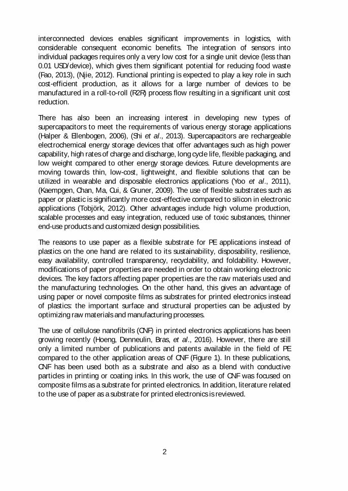
The use of cellulose nanofibrils (CNF) in printed electronics applications has beengrowing recently (Hoeng, Denneulin, Bras, et al., 2016). However, there are stillonly a limited number of publications and patents available in the field of PEcompared to the other application areas of CNF (Figure 1). In these publications,CNF has been used both as a substrate and also as a blend with conductiveparticles in printing or coating inks. In this work, the use of CNF was focused oncomposite films as a substrate for printed electronics. In addition, literature relatedto the use of paper as a substrate for printed electronics is reviewed.
3
Figure 1. Annual number of publications and patents on cellulose nanofibrils and CNin electronics. Source: SciFinder & Espacenet – descriptors. (Hoeng, Denneulin, &Bras, 2016)
The most important advantages of novel composites are their flexibility andrecyclability in addition to low cost that will provide opportunities for new end-useapplication areas such as wearable electronics, throw-away/one-time use-electronics, and consumer packages. The metallic nanoparticles used in printingand coating inks and polymers will affect the obtained conductivity of lines andfeatures in functional devices. Therefore, solutions of dispersions and substrateproperties must be designed to match the requirements of the used printing orcoating process.
The main objective of this work is to understand the influence of the raw materialsand manufacturing phases in novel composite films so that critical properties, suchas porosity, surface roughness and dimensional stability, for printed electronics canbe identified. Manufacturing of inorganic pigment-CMNF composite films aredemonstrated in a semi-pilot scale by the film casting method. Papermanufacturing for printing applications has a long history, whereas CMNF with ahigh pigment loading as composite films for printed electronics is a new researcharea. Modification and optimization of composite raw materials and relevantprocess parameters are required for obtaining working electronic devices.Understanding the interactions between raw materials and printing processes playsa key role in this work. The properties of developed new composites for printedelectronics are investigated. Compatibility between achieved properties andfunctional inks and printing methods is also studied. Finally, several functionalproof-of-concept devices including supercapacitors, transistors, and antennas aredemonstrated and analyzed.
4
2 Review of the literature
2.1 Pigment-cellulose micro-and nanofibril composites (PCMNFs)
2.1.1 Background and manufacturing of CMNFThe global markets of cellulose fibrils (CF) comprise cellulose micro- and nanofibrils(CMF and CNF, combined CMNF), cellulose nanocrystals (CNC), and bacterialcellulose (BC). The major market share is represented by CMNF. In cellulose, theamorphous and crystalline parts are sequentially located in a row along the fiberdirection. Strong hydrogen bonding between hydroxyl groups of the compositeglucose molecules makes it almost impossible to break the crystalline parts ofcellulose. However, the amorphous parts are relatively easy to break usingmechanical refining, homogenization, crushing, or chemical and enzymatictreatments (Hubbe et al., 2008), and these extraction methods can also becombined. In the following sections the main characteristics and productionmethods of both CMNF and CNC are presented.
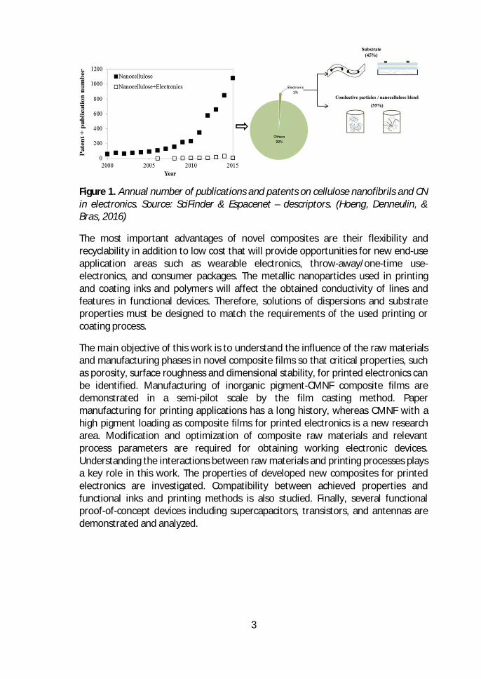
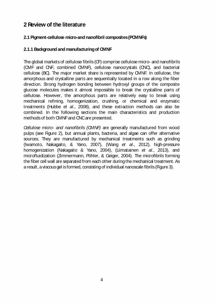
Cellulose micro- and nanofibrils (CMNF) are generally manufactured from woodpulps (see Figure 2), but annual plants, bacteria, and algae can offer alternativesources. They are manufactured by mechanical treatments such as grinding(Iwamoto, Nakagaito, & Yano, 2007), (Wang et al., 2012), high-pressurehomogenization (Nakagaito & Yano, 2004), (Liimatainen et al., 2013), andmicrofluidization (Zimmermann, Pöhler, & Geiger, 2004). The microfibrils formingthe fiber cell wall are separated from each other during the mechanical treatment. Asa result, a viscous gel is formed, consisting of individual nanoscale fibrils (Figure 3).
5
Figure 2. Schematic of the tree hierarchical structure. (Moon, Martini, Nairn,Simonsen, & Youngblood, 2011a).
Figure 3. Left: CNF gel produced by Masuko grinding. Right: Scanning Electronmicroscope (SEM) image of CNFs. Scale: 100 nm (Image source: VTT).
Chemical (e.g. TEMPO oxidation) (Tsuguyuki Saito, Nishiyama, Putaux, Vignon, &Isogai, 2006),(Wågberg et al., 2008) and enzymatic pretreatments (Pääkko et al.,2007), (Zhu et al., 2016), (M. Henriksson, Henriksson, Berglund, & Lindström, 2007)can be combined with mechanical shearing and high-pressure homogenization fordecreased energy consumption during the fibrillation. The goal for both enzymaticand chemical treatments is to loosen the tight hydrogen-bonded structure in thefiber wall. As a result of TEMPO oxidation, C6 hydroxyl groups of native celluloseare converted to carboxyl groups without any changes to the original crystallinity(∼74%) or crystal width of wood celluloses (T. Saito, Okita, Nge, Sugiyama, & Isogai,2006). This leads to highly anionically-charged cellulose microfibrils, of which thezeta-potential values in water are approximately -75 mV (Isogai, Saito, & Fukuzumi,
6
2011). The modification of the fiber structure is followed by an easier liberation offibrils from fibers, which decreases the energy consumption and results in morecost-efficient processes. This has generated a basis for industrialization of CMNFsince 2010. Cationic, anionic, or amphiphilic groups can also be introduced to theCMNF structure by chemical modification.
The fibrils manufactured by a mechanical treatment are flexible and highlybranched and have a high aspect factor (length/width). Typically, wood-basedCMNFs have 20-100 nm cross-sectional size and 1-5 µm fiber length (J. H. Kim et al.,2015), (Siro & Plackett, 2010), (Klemm et al., 2011) and are generally manufacturedin aqueous suspensions. The CMNF-materials usually also contain micro-scale fibrilsand their aggregates, fibers with variable degree of fibrillation, and evenunfibrillated fibers. The aggregates are due to the free hydroxyl groups on thesurface of cellulose fibrils, and the agglomeration takes place especially duringdrying of the CNFs.
On the other hand, cellulose nanocrystals (CNC) are rigid, rod-like nanoparticlescontaining the crystalline parts of cellulose fibers (Rånby, 1951), (Boluk, Lahiji,Zhao, & McDermott, 2011), (Moon et al., 2011a). CNC can be isolated by a mildacid hydrolysis chemical treatment of cellulose. Various acids have been used forthe CNC isolation, in which the amorphous regions are dissolved due to infiltrationof the acid into the accessible amorphous regions. The structure of CNC is verydifferent to that of CMNF. Its diameter is in most cases smaller, from 10 to 50 nm,and the length is also generally shorter to that of CMNF, from 100 to 500 nmdepending on the raw material used (Bras, Viet, Bruzzese, & Dufresne, 2011). CNChas a high surface area and excellent mechanical properties. The films produced byCNC are usually more brittle than those of CMNF, due to their crystalline nature.This work focuses on studying different CMNF grades, with particular emphasis ontheir nanoporous web-like structure and ability to produce smooth and less porousfilms. (Fukuzumi, Saito, Iwata, Kumamoto, & Isogai, 2009).
Commercial production of CF materials
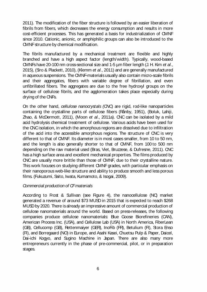
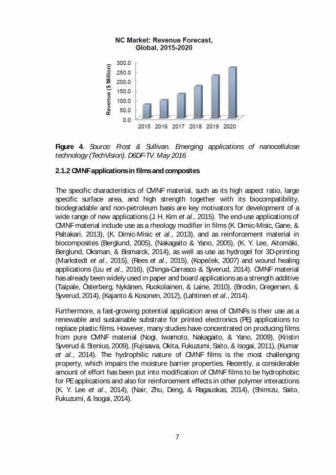
According to Frost & Sullivan (see Figure 4), the nanocellulose (NC) marketgenerated a revenue of around $73 MUSD in 2015 that is expected to reach $268MUSD by 2020. There is already an impressive amount of commercial production ofcellulose nanomaterials around the world. Based on press-releases, the followingcompanies produce cellulose nanomaterials: Blue Goose Biorefineries (CAN),American Process Inc. (USA), and Cellulose Lab (USA) in North America, FiberLean(GB), Cellucomp (GB), Rettenmaiyer (GER), InoFib (FR), Betulium (FI), Stora Enso(FI), and Borregaard (NO) in Europe, and Asahi Kasei, Chuetsu Pulp & Paper, Daicel,Dai-ichi Kogyo, and Sugino Machine in Japan. There are also many moreentrepreneurs currently in the phase of pre-commercial, pilot, or in preparationstages.
7
Figure 4. Source: Frost & Sullivan. Emerging applications of nanocellulosetechnology (TechVision). D6DF-TV. May 2016
2.1.2 CMNF applications in films and compositesThe specific characteristics of CMNF material, such as its high aspect ratio, largespecific surface area, and high strength together with its biocompatibility,biodegradable and non-petroleum basis are key motivators for development of awide range of new applications (J. H. Kim et al., 2015). The end-use applications ofCMNF material include use as a rheology modifier in films (K. Dimic-Misic, Gane, &Paltakari, 2013), (K. Dimic-Misic et al., 2013), and as reinforcement material inbiocomposites (Berglund, 2005), (Nakagaito & Yano, 2005), (K. Y. Lee, Aitomäki,Berglund, Oksman, & Bismarck, 2014), as well as use as hydrogel for 3D-printing(Markstedt et al., 2015), (Rees et al., 2015), (Kopeček, 2007) and wound healingapplications (Liu et al., 2016), (Chinga-Carrasco & Syverud, 2014). CMNF materialhas already been widely used in paper and board applications as a strength additive(Taipale, Österberg, Nykänen, Ruokolainen, & Laine, 2010), (Brodin, Gregersen, &Syverud, 2014), (Kajanto & Kosonen, 2012), (Lahtinen et al., 2014).
Furthermore, a fast-growing potential application area of CMNFs is their use as arenewable and sustainable substrate for printed electronics (PE) applications toreplace plastic films. However, many studies have concentrated on producing filmsfrom pure CMNF material (Nogi, Iwamoto, Nakagaito, & Yano, 2009), (KristinSyverud & Stenius, 2009), (Fujisawa, Okita, Fukuzumi, Saito, & Isogai, 2011), (Kumaret al., 2014). The hydrophilic nature of CMNF films is the most challengingproperty, which impairs the moisture barrier properties. Recently, a considerableamount of effort has been put into modification of CMNF films to be hydrophobicfor PE applications and also for reinforcement effects in other polymer interactions(K. Y. Lee et al., 2014), (Nair, Zhu, Deng, & Ragauskas, 2014), (Shimizu, Saito,Fukuzumi, & Isogai, 2014).
8
The reinforcing effect of CMNF material in polymer composites has been widelystudied mostly in connection with polylactid acid (PLA) as a biodegradable polymer(Oksman, Skrifvars, & Selin, 2003), (Pracella, Haque, Puglia, & Alvarez, 2012),(Aitomäki & Oksman, 2014), (Graupner, Herrmann, & Müssig, 2009), (Trifol et al.,2016), (K. Y. Lee et al., 2014). The mechanical strength of the composites can beimproved with a small addition of CMNF. The increase of tensile modulus can be asmuch as 100% and for tensile strength up to 60%. Several studies have also beenmade with starch (Abdul Khalil et al., 2012), (Subramaniyan & Sun, 2006), (F. Xie,Pollet, Halley, & Av??rous, 2013), synthetic biodegradable poly(vinyl) alcohol (PVA)(Ching, Rahman, Ching, Sukiman, & Chuah, 2015), (S. Y. Lee et al., 2009), andchitosan (Azeredo et al., 2010) together with CMNF in a matrix of composites.These biomaterial combinations open up new possibilities for renewable,biodegradable solutions for future applications.
Manufacturing of neat CMNF films
Neat CMNF films consist of an interconnected CMNF network structure heldtogether by extensive hydrogen bonding. Neat films have remnant porosity in thegaps between particle networks. Neat CN films have typically been produced usingsolution casting techniques from suspensions made of CMF, CNF or CNC both inlaboratory and pilot scale (Moon, Martini, Nairn, Simonsen, & Youngblood, 2011b),(K. Syverud, Xhanari, Chinga-Carrasco, Yu, & Stenius, 2011), (Nakagaito & Yano,2005), (Zimmermann et al., 2004). CMNF material is dispersed with a solids contentof 0.05–5 wt%, typically containing water but other organic media are also used.The casting substrate can be either a solid surface or a filter membrane. Theremaining dispersing medium is removed either by evaporation, vacuum filtration,pressing or by a combination of these methods. The neat films are typically 25–100µm thick and film density varies from 0.8 to 1.5 g/cm³. Additional mechanicalpressing up to 160 MPa has been applied to further densify CMNF films (Nogi et al.,2009). The CMNFs are isotropically oriented in the plane of the film, resulting inisotropic in-plane film properties. To manufacture CNF films for roll-to-rollproduction, the production is based on the precise control of adhesion, andspreading and drying of the CNF on a plastic substrate (Mäkelä, Kainlauri, Willberg-Keyriläinen, Tammelin, & Forsström, 2016). After drying (evaporation of water), thefilm is then separated from the plastic substrate and reeled. Recently, roll-to-rollproduced micro pillars have been fabricated on CMNF neat films using a nano-imprinting method (Mäkelä et al., 2016).
Drying of CMNF material has been studied earlier using different methods such asair drying, freeze drying, spray drying, and supercritical drying (Qing, Sabo, Wu,Zhu, & Cai, 2015), (Y. Peng, Gardner, & Han, 2012), (Y. Peng, Gardner, Han, Cai, &Tshabalala, 2013). The aim has been to preserve the morphology of the CNMFmaterials. The air drying of CMNF suspensions forms a dense material network, andthus other drying methods could be more effective in film applications. In this
9
work, several available drying methods and their combinations, which are typicallyused in paper and board technology, were studied for the PCNMF composites. Thestudied drying methods were drying on a hot metal surface, air impingementdrying, and hot pressing. In the paper and board industry, water from the web afterthe forming section is first removed in the press section and then subsequently inthe drying section. The typical solids content of wet paper web is 45–55% after wetpressing. The amount of water removed by pressing is a function of the appliedpressure, nip width (dwell time), and water viscosity (Walker et al., 1990).Mechanical dewatering is a more cost-efficient way to remove water than dryingbased on evaporation. The most common drying methods for paper, board, andcellulose are cylinder (contact) drying, and air float and air impingement drying.Usually a low steam pressure is used in cylinder dryers, and the drying rates are notvery high, in the range of 10–25 kg/m2/h (Asensio et al., 2007).
2.1.3 CMNF and pigments in composites
Inorganic pigments and fillers are widely used in the paper and board industry. Themost common ones are calcium carbonate, kaolin clay, talc, and titanium dioxide.In the printing industry, the profitability depends on raw material costs, operatingmethods, logistics, and efficiency. The renewable raw material is cellulosic fibers,with a relatively high price, whereas the inorganic mineral pigments are lessexpensive than fibers, with typically approximately 80% lower costs. Thesepigments are also used to improve the dewatering and optical and printingproperties of papers and boards.
From the economical point of view the advantage of replacing fibers with pigmentsis evident. Hence, pigments are an important component in practically all printingand writing papers (R. Subramanian, Fordsmand, & Paulapuro, 2007). Recently,there has been growing interest in increasing the pigment content of papersutilizing CNF as a binding component (Brodin et al., 2014), (Torvinen, Kouko,Passoja, Keränen, & Hellén, 2014), (Macdonald, 2015), (M. He, Cho, & Won, 2016).
The challenge of increasing the pigment content of papers is the decrease inmechanical strength properties. The replacement of fibers by mineral particlessubstantially decreases the bonding between cellulose fibers inside the sheet, thusreducing the dry strength of papers (De Oliveira, Tejado, & Van De Ven, 2009). Thepigments are not able to produce strong bonds with cellulosic fibers. The typicallyused pigment amount is below 40 wt-% in industrial papers due to this reducedbonding ability.
An increased pigment amount will improve the dewatering of pulp furnish. This isalso a significant advantage of using pigments together with CNFs, which incontrast have a disadvantage of a high ability to bind water, resulting in poordewatering properties. The combination of pigments and CNF can therefore lead toimproved drainage, better efficiency of wet pressing, and increased drying rates
10
compared to the manufacturing of pure CNF films. The use of pigments will alsohave an effect on absorption, optical and porosity properties of the papers andcomposites.
The production and study of hybrid materials consisting of CMNF combined withpigments is therefore an attractive field due to the tendency of CMNF to formstrong and porous network structures in which inorganic particles can behomogeneously embedded (Sehaqui, Zhou, Ikkala, & Berglund, 2011). Such flexiblehybrid materials can be used for packaging applications, coatings, and filmcomposites as in this thesis work (Aulin, Salazar-Alvarez, & Lindström, 2012).Moreover, flexible printed electronics and separation membranes can be obtainedwith further modification of hybrid composite structures (Wei, Rodriguez,Renneckar, & Vikesland, 2014). However, in this thesis work the focus was on thePE application area.
CMNF has been studied for use in packaging applications together with claypigments to improve barrier properties (C. N. Wu, Saito, Fujisawa, Fukuzumi, &Isogai, 2012), (Liimatainen et al., 2013), (Österberg et al., 2013). Understanding thestructural properties of PCMNF composite films will also help to predict theirperformance as a coating layer for packaging applications. A rapid productionmethod for combination of CNF and inorganic nanoparticles in laboratory scale waspublished by Sehaqui et al. (Sehaqui et al., 2011). The procedure allowedmontmorillonite to be used up to 50 wt-%. However, only a very limited amount ofdata was available about the formed composite properties.
High strength and high gas-barrier CNF/clay-layered composite films were preparedby mimicking natural nacre, having high transparency and oxygen-barrierproperties despite having low densities (C. N. Wu et al., 2012). Blends of TEMPO-oxidized CNF and inorganic montmorillonite up to 50 wt-% in the matrix had a highmechanical strength and toughness. The produced films were also transparent andflexible. Similarly, high-strength CNF-talc hybrid barrier films manufactured by anano-layered biomimetic technique were studied by Liimatainen et al. (Liimatainenet al., 2013). The inorganic talc content in these studies was also up to 50 wt-%.Talc platelets resulted in a decrease in the moisture absorption in high pigment-loaded experiments, and a low average pore size of the films was obtained.Moreover, transparent CMNF-pigment composite films were manufactured byHonorato et al. (Honorato et al., 2015). The effect of raw materials on compositefilm mechanical, barrier, and optical properties was studied using both clay andcalcium carbonate (CaCO3) combined with softwood and hardwood as a rawmaterial for TCNF. The maximum pigment load in these studies was 25 wt-%. Theuse of clay as a filler material showed more potential to produce better barrier andmechanical properties compared to CaCO3. The agglomeration of CaCO3 particlesresulted in highly brittle films with uneven formation. Aulin et al. also studied highstrength and flexible CMNF-nanoclay hydrid composite films for improved oxygen
11
and water vapor permeability (Aulin et al., 2012). The nanoclay (vermiculite nanoplatelets) portion in experiments was up to 20 wt-%. The obtained films were thin,strong, and transparent, with good barrier properties. Thus, they are promisingcandidates for packaging applications.
The manufacturing of CMNF composite films including a high amount of inorganicpigment and pulp fibres was studied by Rantanen et al. (Rantanen & Maloney,2013), (Rantanen, Dimic-Misic, Kuusisto, & Maloney, 2015). The properties ofCMNF composite papers were studied using different compositions of pigment (upto 70 wt-%), CMNF (in various portions), and pulp fibers (mainly at 10 wt-%). Theoptical properties of the composite papers were excellent, as both a micro- andnanoporous network structure of the paper was obtained. The manufacturing ofcomposite papers was demonstrated in high consistency giving rise to conditionsthat resulted in 33% dry solids content of the web after the wet pressing section.The main outcome of the pilot trials was that pressing requires long pulses toremove water efficiently, and under these circumstances the dewatering can beeven better compared to that of Kraft pulp furnish. Moreover, CMNF compositepapers can be formed using a feasible and economical process in pilot scale.
The FiberLean® Technologies, as a joint venture of Imerys and Omya, hasproduction and a patent for a composite which includes inorganic pigment particlesand CMF material. The process is based on co-grinding of mineral particles and pulpfibers. This composite material can be used as a part of paper and board making inthe wet end addition. The mineral plays an essential role in the transfer ofmechanical energy from regular pulp into CMF. This also allows the use of robustand reliable industrial equipment. A wide range of pulp furnishes can be fed intothe process without any pretreatment. A number of different pigment particlessuch as calcium carbonate, kaolin, graphite, and talc can be used. In futureapplications, FiberLean composite product may also be used as a film material andsubstrate for printed electronics.
2.2 Printed electronics on paper and compositesNowadays there is a growing interest in using flexible composite films as substratesfor printed electronics (PE) applications instead of conventional materials such asglass, silicon and plastic films. The interest in flexible and wearable electronics hasincreased exponentially within the past decade. PE is a combination of traditionalprinting processes of paper and board industry and novel ink chemistry forproduction of electronic components. Moreover, traditional paper coatingtechnologies can be used in a novel way. The goal of PE is to produce flexible, low-cost, and environmentally friendly electronic products. The most common flexiblesubstrates used in PE applications are polymer plastic films.
The motivation for using paper and novel CMNF material films as a substrate for PEapplications to replace plastic films is obvious. Paper is a biocompatible,
12
biodegradable, cost-effective, thin, lightweight, and flexible material that iscommonly available (Tobjörk & Österbacka, 2011), (Chang, Ge, & Sanchez-Sinencio,2012), (Hodgson, 2011). As a porous material, paper also provides a high surfacearea for active components to be embedded and stored on its surface or inside thestructure depending on the application (Dogome, Enomae, & Isogai, 2013),(Öhlund, Örtegren, Forsberg, & Nilsson, 2012), (Ihalainen et al., 2012), (Kattumenu,Rebros, Joyce, Fleming, & Neelgund, 2009), (Hyun et al., 2015), (Choi, Yoo, Lee, &Lee, 2016).
Interest in the use of CMNF films as a substrate for PE applications has recentlybeen growing. The main reason for this is the possibility to manufacturetransparent and flexible films for devices such as solar cells, screens, and sensors(B. Peng & Chan, 2014), (Y. H. Jung et al., 2015), (Yan et al., 2014), (Grau,Kitsomboonloha, Swisher, Kang, & Subramanian, 2014), (Yan et al., 2014). Thereare numerous studies indicating that CMNF films provide a higher smoothness andlower porosity of structure compared to traditional paper. The properties of CMNFfilms are approaching those of polymer plastic films (González et al., 2014), (KristinSyverud & Stenius, 2009).
Processes and applications in PE applications are briefly presented in the followingsections. An overview of using paper and CMNF material in composite films as asubstrate for PE is given. This work concentrates mainly on the use of CMNFmaterial in substrates.
2.2.1 Materials, processes and applications in printed electronics
Printed electronics is a combined technology field with a predicted $73 billionglobal market size by 2025 (Das & Harrop, 2012). A major advantage of usingflexible substrates compared to traditional ones is higher productivity and a loweramount of waste in production. An overview of the PE materials, processes, andapplications is summarized in the following sections.
Materials
Conductive materials for electrical conductive inks are typically conductivepolymers, metallic particles, and carbon-based particles such as graphene andcarbon nanotubes (CNT). Metal nanoparticle inks are traditionally made of gold orsilver with high bulk metal conductivity (even 50% of bulk conductivity) (Setti et al.,2004). However, costs represent a challenge for the widespread use of goldparticles, and therefore silver is the most common choice, offering highconductivity, high resistance to oxidation, and low enough reactivity to be used inambient conditions (Hsieh, Kim, Nogi, & Suganuma, 2013), (Nge, Nogi, &Suganuma, 2013), (L. Xie et al., 2012). The most common conductive silver inks arebased on spherical nanoparticles (NP) or flakes. In recent years, copper has alsobeen studied due to its high bulk conductivity and low cost. The challenge with
13
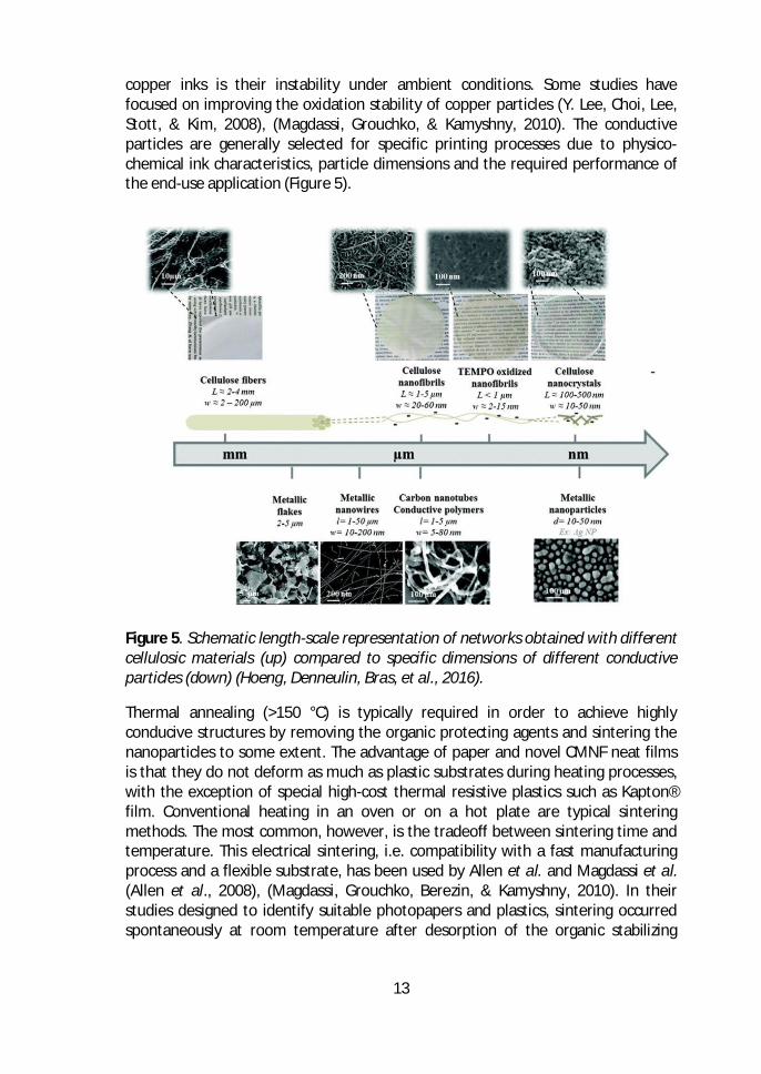
copper inks is their instability under ambient conditions. Some studies havefocused on improving the oxidation stability of copper particles (Y. Lee, Choi, Lee,Stott, & Kim, 2008), (Magdassi, Grouchko, & Kamyshny, 2010). The conductiveparticles are generally selected for specific printing processes due to physico-chemical ink characteristics, particle dimensions and the required performance ofthe end-use application (Figure 5).
Figure 5. Schematic length-scale representation of networks obtained with differentcellulosic materials (up) compared to specific dimensions of different conductiveparticles (down) (Hoeng, Denneulin, Bras, et al., 2016).
Thermal annealing (>150 °C) is typically required in order to achieve highlyconducive structures by removing the organic protecting agents and sintering thenanoparticles to some extent. The advantage of paper and novel CMNF neat filmsis that they do not deform as much as plastic substrates during heating processes,with the exception of special high-cost thermal resistive plastics such as Kapton®film. Conventional heating in an oven or on a hot plate are typical sinteringmethods. The most common, however, is the tradeoff between sintering time andtemperature. This electrical sintering, i.e. compatibility with a fast manufacturingprocess and a flexible substrate, has been used by Allen et al. and Magdassi et al.(Allen et al., 2008), (Magdassi, Grouchko, Berezin, & Kamyshny, 2010). In theirstudies designed to identify suitable photopapers and plastics, sintering occurredspontaneously at room temperature after desorption of the organic stabilizing
14
agents. Other sintering techniques for metal NPs are the argon plasma treatment,microwaves, and various light sources such as IR and UV (Layani, Cooperstein, &Magdassi, 2013), (Tobjörk et al., 2012), (Gaspar, Passoja, Olkkonen, & Smolander,2016), (S. Jung & Kim, 2010), (Wünscher et al., 2012).
The conductivity of conductive polymers and carbon particle inks is about one 100th
of that of silver inks. The advantage of conductive polymers is that they can exhibitconductivity with transparency and flexibility at same time. These polymers alsotolerate higher processing temperatures compared to metal inks. The mostcommon conductive polymer used is poly (ethylene-dioxythiophene):poly(styrenesulfonate) (PEDOT-PSS), which is stable in water. The lowest reported surfaceresistivity on paper was 2.6 Ω , which is twice as high as that on a PETsubstrate (Trnovec et al., 2009). Graphite has been widely used in flexible batteries.Carbon nanotubes and graphene are common materials used to produceconductive layers in low cost energy storage applications (Hu, Wu, & Cui, 2010),(Lehtimäki, Li, et al., 2014), (Tuukkanen et al., 2014), (Lehtimäki, Tuukkanen, et al.,2014). A specific capacity of 33 F/g at a high specific power of 250 000 W/kg wasachieved with an organic electrolyte for CNT films by Hu et al. (Hu et al., 2010).Conductivity of thin films of CNTs is up to 10³-10 S and the surfaceresistivity of 50 nm thick films made of single-wall CNTs (SWCNTs) prepared byvacuum filtration was reported to be 30 Ω (Z. Wu et al., 2004).
Metal nanowires and nanofibers are attractive mainly due to their high aspectratio. The elongated particles can form a percolated network at very lowconcentrations, which makes it possible to produce flexible transparent conductivelayer sheets for wearable applications (Kamyshny & Magdassi, 2014), (Yao & Zhu,2014), (Persano, Camposeo, & Pisignano, 2015) and indium tin oxide (ITO) thinfilms on glass and polymer substrates (Guillén & Herrero, 2005), (Nisha, Anusha,Antony, Manoj, & Jayaraj, 2005).
Printing processes
The most common printing processes for printed electronics are inkjet printing(Jang, Lee, Lee, & Oh, 2013), (Dogome et al., 2013), screen-printing (Chang et al.,2012), (B. Peng & Chan, 2014), flexography (Kattumenu et al., 2009), (Hübler et al.,2011), gravure printing (Zhu et al., 2014), (Hübler et al., 2011), and offset printing(Reuter, Kempa, Brandt, Bartzsch, & Huebler, 2007). The printing technologies haveseveral advantages compared to laboratory scale processes such asphotolithography and vacuum processes: the printing processes are fast and usewidely available low-cost technology. Magazines, books, and newspaper areprinted in trillions of pages annually at a very high speed. New businessopportunities are being surveyed for high volume printing machines, due todecreased graphic paper product consumption. However, the requirements for PEapplications are different compared to those for graphic papers (Tobjörk &Österbacka, 2011), (R Bollström, Tobjörk, & Dolietis, 2012), (Chang et al., 2012). For
15
PE applications, a continuous and homogeneous track is needed for functionality,compared to a good visual impression needed in graphic papers. Therefore, layerthickness, smoothness, and print resolution play crucial roles in PE applications.
Inkjet printing is a non-contact, additive process in which the ink is ejected throughmicrometric nozzles onto the printing substrate. It has high flexibility to usedifferent geometries and applications (Jang et al., 2013), (Sanchez-Romaguera etal., 2015), (Choi et al., 2016). The deposition of thin layers (approximately 0.3-20µm) is possible at a high speed and resolution using low viscosity inks. Therefore,substrate properties are important in terms of controlling ink spreading and toachieve the required print performance and functionality. The limitations of inkjettechnology are in droplet ejection and restriction of particle size for avoiding nozzleblocking. In screen printing, the ink is squeezed through a screen mask using anapplied pressure. The non-printed areas in the screen are blocked by a polymeremulsion which allows the ink to pass through the remaining openings into theprinted area. The ink properties and wire density of the mesh have an effect on theobtained print resolution and thickness. The used ink in screen-printing usually hasa high viscosity and a printed wet layer thickness can be up to 100 µm. Relativelythick layers allow the formation of low resistance structures using conductivepolymers.
In flexography, the applications are mostly related to the fabrication of conductingstructures, transistors, and organic light-emitting diodes (OFETs) (Hübler et al.,2011), (J. Huang et al., 2013), (B. Kang, Lee, & Cho, 2013). A low cost flexible plateis attached to the cylinder and the printed objects are transferred onto the plate.The viscosity of flexography inks is less than that of the screen printing inks. It ispossible to form continuous lines by modifying ink properties (higher viscosity andsurface tension), although the anilox roll itself consists of discrete cells. A limitedsolvent compatibility, swelling and ink squeezing at high print pressure, and lowviscosities cause problems in flexographic printing processes. Gravure printing haspreviously been widely used in high volume printing processes for producingconductive structures such as antennas (Zhu et al., 2014) and organic solar cells(Hübler et al., 2011). The printed structures are engraved into a metallic cylinder bylaser, chemical etching, or electromechanically, and a high print resolution can beobtained by gravure printing. The gravure rolls are expensive to manufacture butuseful for large volume printing applications. The offset (lithography) printingtechnology requires high viscosity inks with suitable surface tension for printedpatterns. The offset printing is based on wetting differences, with the offsetprinting roll having different surface energy areas. The non-printing areas areusually wetted with fountain water before transferring the ink onto the imageareas. The printing process is indirect: the ink is first transferred to an intermediatecylinder and then to the image areas on substrate. The offset method is ratherlimited for PE applications due to the presence of water and the viscoelasticproperties of the ink.
16
Coating technologies including spray technology (Zheng, Li, Shi, & Yu, 2014),(Azarova et al., 2010), slot die (Krebs, 2009), (H. Kang, Park, & Shin, 2014), and barand blade coating (Pierre et al., 2014), (Lehtimäki, Pörhönen, et al., 2014) can alsobe used to produce conductive layers. These coating technologies can provide largescale, fast, and easy processes to scale up the roll-to-roll production. Thelimitations of coating methods are the impossibility to produce detailed patternsand a high level of waste production. However, for energy storage applications,rapid production of conductive layers of graphene and CNT inks can be achievedusing coating technologies (Lehtimaki et al., 2014).
Applications
Applications for printed electronics include, for example, energy storages (Hu et al.,2010), (X. He, 2015), transistors (Fredrik Pettersson, Remonen, et al., 2015) (Grauet al., 2014), (Eda & Chhowalla, 2009), displays (Berggren, Nilsson, & Robinson,2007), (X. Xu et al., 2016), antennas (Zhu et al., 2014), (Rida, Yang, Vyas, &Tentzeris, 2009), and solar cells (Krebs, 2009), (Kamyshny & Magdassi, 2014).Electronic components can be divided into two groups: passive and active. Theantennas, inductors, capacitors, conducting wires, and fibers are classified aspassive components, whereas transistors, diodes, memories, solar cells, and energystorages such as batteries and supercapacitors are considered as active ones.Basically, all PE applications need some kind of power source such as a battery,capacitor or solar cell. The transistors are probably the most fundamentalcomponents needed, but at the same time are the most challenging ones to befabricated. The functional devices e.g. sensors can also work without electricity, forexample based on colorimetric indicators. In the following sections the mostcommon PE components for flexible substrates are summarized.
Energy storages consist of capacitors, batteries, and solar cells. A capacitor isfabricated with two electrodes separated by an electrolyte. Thin, even papers havebeen used as separators. The capacitor structure is filled with a non-aqueous oraqueous electrolyte. The electrostatic charge is stored in the form of an electricdouble layer at the interface of the electrolyte and electrodes. Therefore, energy isstored by the mechanism of charge polarization. The structure of a battery issimilar to that of a capacitor, but the electric charge is stored as chemical energyvia the electrochemical redox reaction in the electrode materials. There are alreadysome commercial thin-film batteries fabricated in paper on the market, producede.g. by Enfucell Oy, Power Paper, and Blue Spark Technologies utilizing screenprinting and lamination. Recycling of these novel batteries is still a challenge due tothe metals used in the batteries. Therefore, development of the recycling processand eco-design were recently investigated (Georgi-Maschler, Friedrich, Weyhe,Heegn, & Rutz, 2012), (Larcher & Tarascon, 2015). Solar (photovoltaic) cells are analternative energy source to batteries or capacitors (Eom et al., 2009), (Galagan etal., 2013). The most potential use of solar cells is considered to be in large area and
17
flexible applications on the roofs of buildings. The working principle of bulkheterojunction solar cells is that the donor and acceptor materials represent thekey semi-conductive materials, enabling release of electrons when exposed to light.Glass, polymer plastics, and also recently CNF films have been used as substratesfor organic solar cells (Costa, Pingel, Janietz, & Nogueira, 2016).
There has been increasing interest in developing new types of supercapacitors, alsocalled ultracapacitors, to meet the requirements of energy storage applications(Halper & Ellenbogen, 2006), (Kaempgen et al., 2009), (F. Pettersson et al., 2014),(Shi et al., 2013). Supercapacitors are rechargeable electrochemical energy storagedevices that offer the advantages of high power capability, high rates of charge anddischarge, long cycle life, flexible packaging, and low weight compared to otherenergy storage devices. Future developments are moving towards thin, low-cost,lightweight, and flexible solutions that can be utilized in wearable and disposableelectronics applications. An emerging field of energy harvesting applications, forexample, from light, RF fields, or vibrations lacks complementary energy storagesolutions (Radousky & Liang, 2012), (H. S. Kim, Kim, & Kim, 2011). Low-cost,flexible, metal-free, non-toxic, and disposable supercapacitors produced byefficient processes are needed for applications in PE systems. Nanostructuredcarbon materials such as CNT and graphene are promising future materials forsupercapacitors due to their excellent electrical conductivity and high surface area(An et al., 2001), (Z. Chen et al., 2011), (T. Chen & Dai, 2013), (Y. Huang, Liang, &Chen, 2012)
Transistors are used as electronic components in displays and logic gates in digitalcircuits. A logic inverter can be made by simply connecting a transistor to a resistoror a second transistor. The field-effect transistor (FET) is a transistor that uses anelectric field to control the electrical behavior of the device. The structure of FETconsists of at least four layers: source and drain electrodes, semiconductor, gatedielectric (insulator), and gate electrode. In organic FETs (OFETs) thesemiconductor film includes organic polymers. The high operation voltages (10–100 V) are the main challenge of traditional OFETs for portable solutions.Therefore, a low operation voltage is required if batteries, solar cells, or otherforms of electromagnetic induction are used together with OFETs. Humidity alsoincreases the risk of electric shocks or irreversible electrochemical reactions at highvoltages. The deposition methods and substrate characteristics will also have aneffect on the transistor performance, in addition to the transistor type, the rawmaterials used, and the dimensions.
There is growing interest in electronic memory devices, actuators, displays, andRFID tags to be used in future PE applications. RFID tags can be used as areplacement for optical barcodes for keeping track of products. There is a largemarket potential if these tags can be manufactured at a low cost onto flexible,environmentally friendly substrates. The active RFID tags are powered by batteries
18
for long reading distances (up to 30 m), whereas passive tags are powered by thereader device (up to 3 m). In addition to the antenna, RFID tags usually need acapacitor, a rectifier, and a transponder that consists of transistor circuits andmemory. The identification data is read from the memory and sent to themodulator. The modulator (e.g. a transistor) modulates the energy, which isabsorbed by the antenna. The reader will then sense and decode the energy.Reading of the data requires the presence of an electric field, where the passiveRFID tag and antenna will be exposed (V. Subramanian et al., 2006), (Chan, Kung, &Pei, 2005), (Tobjörk & Österbacka, 2011).
2.2.2 Papers and novel composites for printed electronics
The interest in using paper and novel CMNF material films and composites hasincreased due to the needs of bio-based material, low cost, recyclable, and flexiblesubstrates for PE applications. There have been many recent advances in the fieldof paper electronics. The obtained conductivity or resistivity of electronic devicesdepends strongly on the used printing or coating processes and conductivematerials. Overall, the critical parameters cannot be established due to theindividual main characteristics of each electronic device. However, the sectionsbelow summarize the main findings in the field of paper and CMNF as a substratefor PE applications.
The main requirements for substrate properties are smoothness, moisture andthermal resistivity, low porosity, durability, flexibility, dimensional stability,stiffness, and optical transparency depending on the target application. The barrierproperties of paper also play an important role in some end-use applications (Grauet al., 2014). Moisture and gas vapor barrier properties can be enhanced usingdifferent coatings and special surface treatments (Brodin et al., 2014). The porosityof paper will also affect transmission rates, i.e. the transmission rate will bereduced by increasing the tortuosity. The low porosity and small pore sizes will alsoreduce the transmission rates of gases and their penetration into the substrate.The smoothness of traditional papers can be improved using pigments and CMNFmaterial (Brodin et al., 2014), (Bundy & Ishley, 1991). Paper can also be coated bymultiple layers in order to achieve accurate print quality. In many cases, forexample, calendering is needed to obtain sufficient characteristics. Anotherapproach to produce smooth and non-absorbing substrates for PE components isto use functional coatings or polymer lamination with for example polyethylene(PE), polypropylene (PP), polyethylene terephthalate (PET), wax, or aluminium. Therecyclability and sustainability might also present challenges in these applications.
A multi-layer coated special paper was developed by Bollström et al. (RogerBollström et al., 2009). It was demonstrated that sufficiently high smoothness wasachieved and that transistors could be fabricated onto it. The authors alsodemonstrated that a multi-layer coated paper can be used as a substrate for roll-
19
to-roll processes (R Bollström et al., 2012). Trnovec et al. used special coatings ofmineral pigments, kaolin and CaCO3 and binders, polyvinyl alcohol (PVA), starchand latex for paper in order to achieve high smoothness for PE applications(Trnovec et al., 2009). The mechanical and electronic properties of the actuatorswere studied on hybrid composite and cellulose-based films by Kim et al (J. Kim etal., 2010). In many studies the RFID tag was assembled on paper together with aninkjet printed antenna and wires (Rida et al., 2009), (Sanchez-Romaguera et al.,2015). Paper-based capacitive touch-pads and direct writing on paper with silvernanowire inks were demonstrated by Li et al. (R. Z. Li, Hu, Zhang, & Oakes, 2014)and Mazzeo et al. (Mazzeo et al., 2012).
Paper and paper-like batteries and energy storages have attracted widespreadattention. A simpler production of PE applications can be achieved if the powersource can be integrated directly to the paper (Hu et al., 2010), (Tuukkanen et al.,2014), (Andersson, 2012), (Choi et al., 2016). Moreover, in these applications therougher surface of paper and a porous structure can be beneficial. The iontransport across the entire structure is possible and high-power performance canbe achieved.
New paper-based products are already on the market. The Arjowiggins“PowerCoat” is a pure, cellulose-based coated paper with a high smoothnesspolymer-like coating. The resolution of printed features is up to 5 µm. The paper isrecyclable and can easily be bended, folded, and torn. Felix Schoeller has alsointroduced a special paper for PE markets, called “p_e:smart” and having anextremely smooth surface and excellent dimensional stability even at hightemperatures. RR Donnelley’s RFID Tag Solutions produce a printed electronicsplatform in which antennas printed directly onto a paper will eliminate the need ofusing additional PET substrates. This may also lead to thinner labels, lower materialcosts, and faster production cycles. It also eliminates the need for a chemicaletching process.
The novel CMNF materials provide possibilities for cellulose-based substrates in thePE field. Highly transparent, flexible, and recyclable films can be produced withCMNF materials. Several recent publications have studied PE applications in pureCMNF films (Hu et al., 2009), (Koga et al., 2014), (Hsieh et al., 2013), (Zhu et al.,2014), (Yan et al., 2014), (J. Huang et al., 2013), (Hoeng, Denneulin, & Bras, 2016).Composite CMNF and polymer films were studied by Martin et al. (Martin & Jean,2014). They showed that physical properties of a thin film, including mechanicalproperties, can be tuned using layer-by-layer assembly techniques. Koga et al.compared vacuum filtration, coating, and spin coating methods on CMNFnanopaper (Koga et al., 2014). Vacuum filtration provided the best results in termsof conductivity of silver nanowires and CNF, as compared to the coating methods.A major advantage of using 100% cellulose films is their sustainability. Thepossibility of recycling a transparent and smooth CMNF film used as a solar cell
20
device was studied by Zhou et al. (Zhou et al., 2013). Simple immersion of the solarcell in water was used, followed by swelling and dissolution of the CNC substrate.The solar cell components were separated by washing and filtration. Thedemonstrated recycling procedure was environmentally friendly andstraightforward. The other way of recycling was to combust the solar cells,whereupon the CNC material goes with the ashes, and the metal components canbe recovered. In addition, Jung et al. demonstrated a new method by biologicaldegradation of the CNF substrates (Y. H. Jung et al., 2015). Fungal degradation wasfound to be successful for both 100% CNF films and also for CNF-coated epoxyfilms. After a certain encapsulation time (84 days), the electronic components wererecovered.
The grand challenge for using neat PCMNF films for future consumer products isdue to the water sorption. Approaches need to be developed to investigate neweffective mechanisms to alter he hygroscopic nature of CMNF materials. Solutionsfor this purpose will improve barrier properties of CMNF-based films and thusprovide better prevention properties for gases in PE applications. This will requiremore detailed knowledge of interface characterization and mechanisms of CMNFwithin the matrix of polymers and pigments. More work is needed to developcharacterization tools and then to analyze interfaces, e.g. their geometry,thickness, and physical properties which can be used as input values for variousmodels. The variation in properties according to various length scales of CMNFmaterial and its influences on the macroscopic properties of neat composites filmsneed to be further clarified, although some answers were found in this thesis work.The cost challenge of pure neat CMNF films can be tackled by using low-costpigments, and this thesis work provided some new solutions in this area.
This work demonstrates the fabrication of nanoporous composite films containingCMNFs and mineral pigment in the form of kaolin clay or PCC particles. After anextensive literature survey of pure CMNF films and also several inorganic andCMNF material mixtures for composite films, a few relevant publications werefound that combine pigment-CMNF films in PE applications (Hoeng, Denneulin, &Bras, 2016). The developed PCMNF composites have a nanoporous pigment-fibernetwork structure allowing control of the ink absorption properties. Therefore,high quality functional printing is possible on these smooth, low cost, andnanoporous surfaces. Currently, considering the price of CMNF material, it isbelieved that their use should be emphasized in PE applications with the use of alower amount of additive. However, it is noteworthy that the electricalperformance of PE applications cannot compete with conventional electronics, andwill therefore find alternative end-uses where other aspects than the electricalperformance are important.
21
3 Materials and methods3.1 Composite raw materials
3.1.1 Mineral pigments
Precipitated calcium carbonate (PCC)
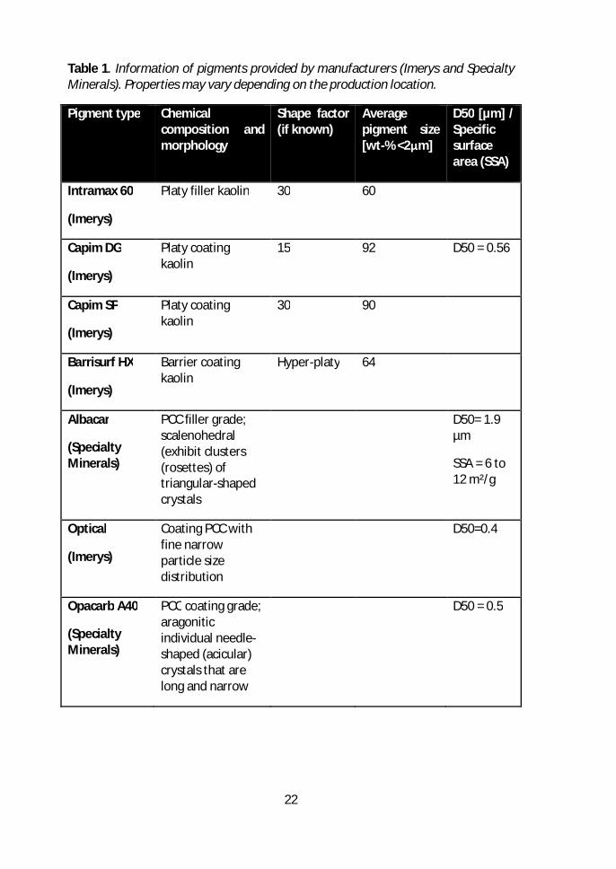
Precipitated calcium carbonate (PCC) pigment was produced synthetically by areaction between slaked lime and carbon dioxide. In this work, two differentcommercial types of PCC were used in laboratory scale: Rosette shaped Albacar(Specialty Minerals Inc.) in Papers I, II and IV, and rhombohedral OptiCal CP(Imerys) in Paper I. Aragonite-shaped Opacarb A40 PCC (Specialty Minerals Inc.)was used in semi-pilot scale in Paper IV.
Kaolin
Kaolin consists of hydrated aluminosilicate in which kaolinite is the dominantmaterial. Kaolinite has a layered structure with a particle shape and size dependingon the pigment origin. In this work, plate-shaped Intramax 60 (Imerys) was used askaolin filler in laboratory and pilot scale in Papers I-IV. In addition, two platy kaolingrades, Capim SP (Imerys) and a coating grade Capim DG (Imerys) were used in thepilot-scale trials in Paper IV. The pigments used in the laboratory scale studiesincluded platy kaolin Capim SP (Imerys) and ultra-platy crystal kaolin HX spray driedBarrisurf™ (Imerys) in Paper V.
22
Table 1. Information of pigments provided by manufacturers (Imerys and SpecialtyMinerals). Properties may vary depending on the production location.
Pigment type Chemicalcomposition andmorphology
Shape factor(if known)
Averagepigment size[wt-% <2μm]
D50 [µm] /Specificsurfacearea (SSA)
Intramax 60
(Imerys)
Platy filler kaolin 30 60
Capim DG
(Imerys)
Platy coatingkaolin
15 92 D50 = 0.56
Capim SP
(Imerys)
Platy coatingkaolin
30 90
Barrisurf HX
(Imerys)
Barrier coatingkaolin
Hyper-platy 64
Albacar
(SpecialtyMinerals)
PCC filler grade;scalenohedral(exhibit clusters(rosettes) oftriangular-shapedcrystals
D50= 1.9µm
SSA = 6 to12 m²/g
Optical
(Imerys)
Coating PCC withfine narrowparticle sizedistribution
D50=0.4
Opacarb A40
(SpecialtyMinerals)
PCC coating grade;aragoniticindividual needle-shaped (acicular)crystals that arelong and narrow
D50 = 0.5
23
3.1.2 Cellulose micro- and nanofibrils (CNF and CMF)
Cellulose microfibrils (CMF) used in Papers I–II was a commercial product Celish KY100G from Daicel Chemicals ltd., Japan. The cellulose nanofibrils (CNF) in Papers II–III were made from a once-dried bleached hardwood (birch, Betula L.) The CNF wasobtained after eight passes through a super mass colloider grinder (Masuko Sangyotype MKZA10-15J, Masuko Sangyo Ltd., Kawaguchi, Saitama, Japan) by using adecreasing gap width and an increasing operating power. The rotation speed wasset to 1500 rpm.
TEMPO-oxidized cellulose nanofibrils (TCNF) were produced from never-driedbleached softwood Kraft pulp in Paper V. The pulp fibers were fibrillated by a two-pass treatment using a Microfluidizer M7115-30 after oxidation. Never-driedbleached softwood Kraft pulp was the source of native (CNF) and enzymatic (ECMF)grades. The same source material was used as an unbleached grade forlignocellulosic grade (LCNF). The fibril cellulose gels (CNF and LCNF grades) wereobtained after six passes through a Masuko grinder with a rotation speed of 1500rpm. Enzymatic grade (ECMF) was processed at a high consistency (20–30% drysolids content) using cellobiohydrolase (CBH) enzymes and low energy mixing.
3.1.3 Characterization of cellulose micro- and nanofibrils (CMNF)
Optical microscopy was used to characterize the CMNF materials, using Congo Red(0.5%) and Toluidine Blue (0.1%) as marker colors. Rheological properties, includingstorage modulus, loss modulus and shear viscosity, for the studied CNF grades(CNF, LCNF, ECMF and Daicel) were measured using a rotational rheometer at aconsistency of 0.5% (Anton Paar MCR301, ST22.4V vane spindle method). VTT finegrade (Papers II–III) rheological properties were measured using a Brookfieldrheometer model RVDV-III Ultra at 1.5% consistency using vane type spindles.
Water retention of the CMNF grades (CNF, ECMF, TCNF and LCNF) in Paper V wasmeasured using a modified SCAN-C 62:00 (ÅAGWR method). The capacity of thefibrillated material to hold water under centrifugal force and pressure filtration wasmeasured. The method illustrates the level of fibrillation and the network structureof material. The charge of cellulosic gels was measured according to the standardSCAN-CM 65:02. The amount of residual fibers was measured using a KajaaniFiberlab analyzer. The estimation for non-fibrillated fraction was made using thestarting initial material and produced CNF material, which were analyzed based onthe amount of detected fibers and the concentration of the suspension.
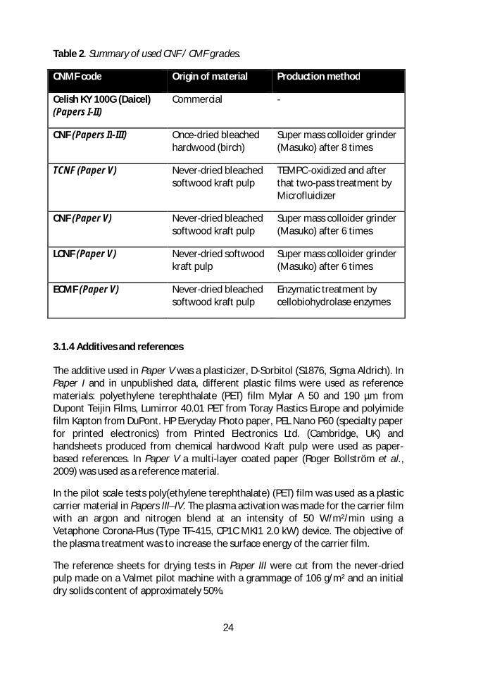
24
Table 2. Summary of used CNF / CMF grades.
CNMF code Origin of material Production method
Celish KY 100G (Daicel)(Papers I-II)
Commercial -
CNF (Papers II-III) Once-dried bleachedhardwood (birch)
Super mass colloider grinder(Masuko) after 8 times
TCNF (Paper V) Never-dried bleachedsoftwood kraft pulp
TEMPO-oxidized and afterthat two-pass treatment byMicrofluidizer
CNF (Paper V) Never-dried bleachedsoftwood kraft pulp
Super mass colloider grinder(Masuko) after 6 times
LCNF (Paper V) Never-dried softwoodkraft pulp
Super mass colloider grinder(Masuko) after 6 times
ECMF (Paper V) Never-dried bleachedsoftwood kraft pulp
Enzymatic treatment bycellobiohydrolase enzymes
3.1.4 Additives and references
The additive used in Paper V was a plasticizer, D-Sorbitol (S1876, Sigma Aldrich). InPaper I and in unpublished data, different plastic films were used as referencematerials: polyethylene terephthalate (PET) film Mylar A 50 and 190 µm fromDupont Teijin Films, Lumirror 40.01 PET from Toray Plastics Europe and polyimidefilm Kapton from DuPont. HP Everyday Photo paper, PEL Nano P60 (specialty paperfor printed electronics) from Printed Electronics Ltd. (Cambridge, UK) andhandsheets produced from chemical hardwood Kraft pulp were used as paper-based references. In Paper V a multi-layer coated paper (Roger Bollström et al.,2009) was used as a reference material.
In the pilot scale tests poly(ethylene terephthalate) (PET) film was used as a plasticcarrier material in Papers III–IV. The plasma activation was made for the carrier filmwith an argon and nitrogen blend at an intensity of 50 W/m²/min using aVetaphone Corona-Plus (Type TF-415, CP1C MKI1 2.0 kW) device. The objective ofthe plasma treatment was to increase the surface energy of the carrier film.
The reference sheets for drying tests in Paper III were cut from the never-driedpulp made on a Valmet pilot machine with a grammage of 106 g/m² and an initialdry solids content of approximately 50%.
25
3.2 Manufacturing of composites
3.2.1 Forming
The composites were manufactured by vacuum filtration in laboratory scale and byfilm casting in semi-pilot scale. The forming methods are described in this section.In this work, pressing and drying processes were studied extensively, and themethods were developed during the work. All the studied pressing, drying, andcalendering methods are outlined here.
Vacuum filtration in laboratory scale (Papers I, II and V)
The composites including mineral pigment and CMNF were produced by vacuumfiltration in laboratory scale in Papers I, II and V. The CMNF material was activatedin a 0.2–0.5% dry solids content using a high shear mechanical mixing. The mixingwas done using, for example, IKA or NETZSCH Shearmaster for approximately 15minutes at room temperature, and deionized water was used as a diluter. Themineral pigments were dispersed to 18–20% dry solids content using a mixer. Thepigments were then diluted together with CMNF material to a forming consistencyof 0.2%. Pigment-CMNF suspension was filtered through a sintered glass funneldevice with a pressure of 0.8 bar. A blue stripe Whatman filter paper with aporosity of 10–16 µm was used in the glass funnel to retain both micro- andnanoscale fibrils and pigments.
Film casting in semi-pilot scale (Papers III and IV)
The semi-pilot scale composites were manufactured using a solvent casting methodat a coating pilot line (Coatema® Coating Machinery GmbH, Dormagen, Germany).The suspension included 80 wt-% of pigment and 20 wt-% of CNF. The componentswere dispersed using high shear forces in a dissolver Diaf 100WH for 50 minutes at400 rpm. The pigment-CMNF suspension at 7% dry solids content was formed bythe applicator with a speed of 2 m/min on plastic film. The web width was 300 mmwith a length of 6–8 m. The grammage of the slightly wet pressed compositesvaried between 150 and 220 g/m², and there was a similar variation in the initialsolids content in the range of 20–35%. (Paper III and IV)
3.2.2 Wet pressing
A gentle wet pressing of filtered composites was performed directly after forming.The composites were pressed according to the procedure described in Figure 6. Theinitial pressing was performed by passing a metal roller ten times over thecomposites. The composites were sandwiched between the filter and boardpapers. Glass or metal plates were used as rigid supporting materials. The smoothfilter paper was used together with board samples to absorb the excess water.
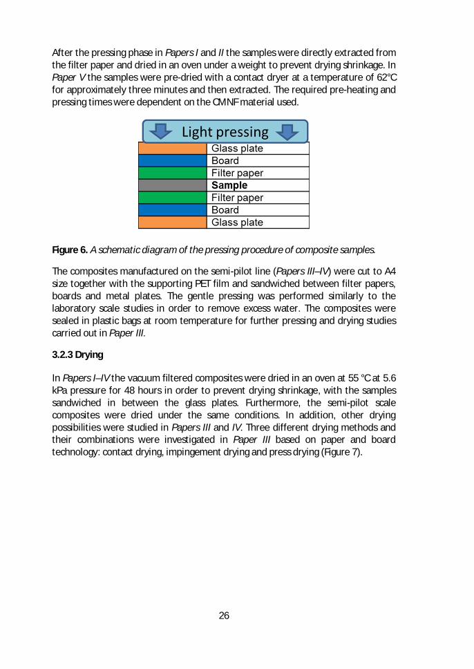
26
After the pressing phase in Papers I and II the samples were directly extracted fromthe filter paper and dried in an oven under a weight to prevent drying shrinkage. InPaper V the samples were pre-dried with a contact dryer at a temperature of 62°Cfor approximately three minutes and then extracted. The required pre-heating andpressing times were dependent on the CMNF material used.
Figure 6. A schematic diagram of the pressing procedure of composite samples.
The composites manufactured on the semi-pilot line (Papers III–IV) were cut to A4size together with the supporting PET film and sandwiched between filter papers,boards and metal plates. The gentle pressing was performed similarly to thelaboratory scale studies in order to remove excess water. The composites weresealed in plastic bags at room temperature for further pressing and drying studiescarried out in Paper III.
3.2.3 Drying
In Papers I–IV the vacuum filtered composites were dried in an oven at 55 °C at 5.6kPa pressure for 48 hours in order to prevent drying shrinkage, with the samplessandwiched in between the glass plates. Furthermore, the semi-pilot scalecomposites were dried under the same conditions. In addition, other dryingpossibilities were studied in Papers III and IV. Three different drying methods andtheir combinations were investigated in Paper III based on paper and boardtechnology: contact drying, impingement drying and press drying (Figure 7).
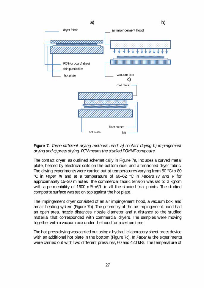
27
Figure 7. Three different drying methods used: a) contact drying b) impingementdrying and c) press drying. PCN means the studied PCMNF composite.
The contact dryer, as outlined schematically in Figure 7a, includes a curved metalplate, heated by electrical coils on the bottom side, and a tensioned dryer fabric.The drying experiments were carried out at temperatures varying from 50 °C to 80°C in Paper III and at a temperature of 60–62 °C in Papers IV and V forapproximately 15–20 minutes. The commercial fabric tension was set to 2 kg/cmwith a permeability of 1600 m³/m²/h in all the studied trial points. The studiedcomposite surface was set on top against the hot plate.
The impingement dryer consisted of an air impingement hood, a vacuum box, andan air heating system (Figure 7b). The geometry of the air impingement hood hadan open area, nozzle distances, nozzle diameter and a distance to the studiedmaterial that corresponded with commercial dryers. The samples were movingtogether with a vacuum box under the hood for a certain time.
The hot press drying was carried out using a hydraulic laboratory sheet press devicewith an additional hot plate in the bottom (Figure 7c). In Paper III the experimentswere carried out with two different pressures, 60 and 420 kPa. The temperature of
PCN (or board) sheet
thin plastic film
hot plate
dryer fabric
a)air impingement hood
vacuum box
b)
felt
filter screen
cold plate
hot plate
c)
28
the pre-heated plate was either 80 or 110 °C and the size of the sample was 160 ×160 mm² with a thickness of 25 mm.
In Paper IV, semi-pilot scale composites were dried either in an oven or using acontact dryer with varying parameters. In Paper V, the contact dryer was the onlydrying method used.
Throughout the drying experiments performed in Paper III, the moisture ratiowas obtained from
[ ]kgkgd
dii m
mmMR -= (1)
where is the initial mass of sample before drying and the final mass ofsample after keeping it in an oven for 2 hours at a temperature of 105 °C after thedrying experiments.
3.2.4 Calendering
The composites were conditioned for at least 24 h in standard climate conditions(temperature 23 °C and 50% relative humidity, RH) after the drying and beforecalendering and physical testing. The composites were single pass calendered usinga laboratory scale calender with a hard roll nip. The applied pressure wasapproximately 20 MPa, with a surface temperature of the lower roll of 150–170°C(Papers I–V).
3.3 Printing
3.3.1 Inkjet-printed conductive lines (Papers I and II)
Inkjet printing was studied using a silver nanoparticle ink in Papers I and II.Conductive patterns were printed using a Dimatix DMP-2800 inkjet printer oncomposites using AGP Silverjet DGP (30LT) ink from ANP Co. Ltd., Seoul, Korea inPaper I. The silver ink was sintered in an oven at 125 °C for 60 minutes. Ink layerswere printed for composites and for the reference PET film (Mylar A). The layoutfor the test platform included 20 mm long lines with contacting pads at both lineends. A multimeter Fluke 175 was used to measure the resistance of the silverlines, given by
R = l / (σ × w × h) (2)
where l is length, w is width, and h is thickness of conductive lines, and σ isconductivity of the material. The sheet resistance Rs can be calculated from
29
Rs = 1 / (σ × h)= R × w / l , (3)
where Rs is the resistance of a square shaped conductor (l=w) with uniformthickness.
AGP Silverjet DGP (30LT) silver nanoparticle ink was used in Paper II for printingconductive patterns. The inkjet printing was carried out using Autodrop System(Microdrop Technologies) with an MD-K-130 dispenser head (50 ml size of thenozzle). Four-point resistance measurement was performed using an Abilent 34970data acquisition unit for 10 mm effective sample lengths. The composites weresintered on an Instec hot plate at 220 °C for 300 or 600 seconds. In addition, theheight and width of conductive lines were measured using a surface profiler (WykoNT9100, Veeco Instruments Inc. Arizona USA) in vertical scanning interferometrymode from an area of approximately 1.2 mm².
3.3.2 Screen-printed and spray-coated supercapacitors (Paper IV)
Screen-printing was used for electrodes with a conductive commercial grapheneink (Vor-ink X103, Vorbeck). The electrodes were printed on both sides of thecomposite. The samples were dried in an oven at 120 °C for two minutes afterprinting. Further drying for ten minutes was performed after all layers had beendeposited in order to ensure proper ink drying. In addition, a spray-coating methodwas used for producing carbon nanotube (CNT) electrodes on both sides of thecomposite. The used CNT-xylan nanocomposite ink was produced by Nemcel(Lehtimäki, Tuukkanen, et al., 2014). The structure of a supercapacitor wasobtained on both of these manufactured electrodes. The ink contained 3.0 wt-%CNT with 1.5 wt-% xylan in a water suspension. A PET mask was used to define theelectrode area during the spray-coating.
The length of the graphene electrodes was 3.2 cm, with a width of 1.4 cm having anoverlap of 1.4 cm that produced an active device area of 2 cm² (Figure 8). Theactive area of the supercapacitor was soaked in aqueous NaCl (1 M) suspensionduring the measurements.
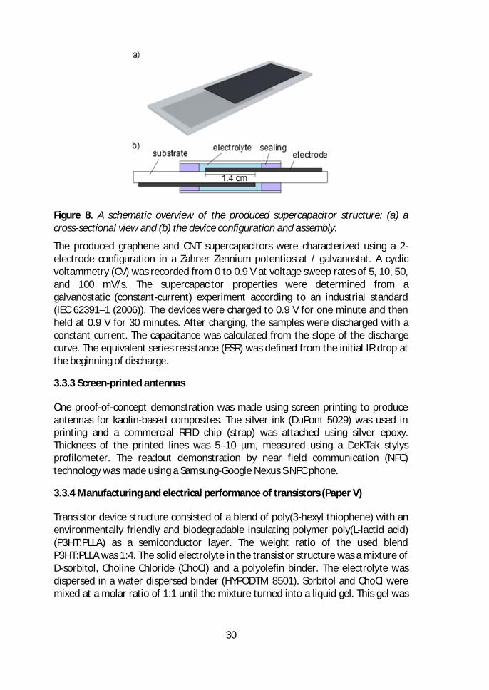
30
Figure 8. A schematic overview of the produced supercapacitor structure: (a) across-sectional view and (b) the device configuration and assembly.
The produced graphene and CNT supercapacitors were characterized using a 2-electrode configuration in a Zahner Zennium potentiostat / galvanostat. A cyclicvoltammetry (CV) was recorded from 0 to 0.9 V at voltage sweep rates of 5, 10, 50,and 100 mV/s. The supercapacitor properties were determined from agalvanostatic (constant-current) experiment according to an industrial standard(IEC 62391–1 (2006)). The devices were charged to 0.9 V for one minute and thenheld at 0.9 V for 30 minutes. After charging, the samples were discharged with aconstant current. The capacitance was calculated from the slope of the dischargecurve. The equivalent series resistance (ESR) was defined from the initial IR drop atthe beginning of discharge.
3.3.3 Screen-printed antennas
One proof-of-concept demonstration was made using screen printing to produceantennas for kaolin-based composites. The silver ink (DuPont 5029) was used inprinting and a commercial RFID chip (strap) was attached using silver epoxy.Thickness of the printed lines was 5–10 µm, measured using a DeKTak stylysprofilometer. The readout demonstration by near field communication (NFC)technology was made using a Samsung-Google Nexus S NFC phone.
3.3.4 Manufacturing and electrical performance of transistors (Paper V)
Transistor device structure consisted of a blend of poly(3-hexyl thiophene) with anenvironmentally friendly and biodegradable insulating polymer poly(L-lactid acid)(P3HT:PLLA) as a semiconductor layer. The weight ratio of the used blendP3HT:PLLA was 1:4. The solid electrolyte in the transistor structure was a mixture ofD-sorbitol, Choline Chloride (ChoCl) and a polyolefin binder. The electrolyte wasdispersed in a water dispersed binder (HYPODTM 8501). Sorbitol and ChoCl weremixed at a molar ratio of 1:1 until the mixture turned into a liquid gel. This gel was
31
then mixed with the water-dispersed binder. The electrolyte was finally spin castedat 3 000 RPM for 30 s. Water evaporated during the casting process, resulting in asolid film containing approximately 50% sorbitol/ChoCl and 50% binder. Thesource-, drain-, and gate electrodes were all thermally evaporated at approximately10 mbar pressure. All transistor devices were fabricated and measured in anitrogen atmosphere. (Roger Bollström et al., 2009), (Fredrik Pettersson et al.,2014), (Fredrik Pettersson, Remonen, et al., 2015), (Fredrik Pettersson, Adekanye,& Österbacka, 2015).
The transistors were characterized by measuring transfer curves in a saturationmode, where the drain voltage (VD) was kept at -1 V and the gate voltage (VG) wasswept from 0 V to -1.2 V and back to 0 V. The figures of merit (FOMs) wereextracted from the measured transfer curves. These include the drain current ( )measured at VG = -1.2 V (ON-current), measured at the point where VG starts toincrease logarithmically (OFF-current), the ratio between the ON- and OFF-current(ON/OFF-ratio), the gate current at VG = -1.2 V (leakage) and the ratio between theleakage current and the ON-current (leakage/ON-current).
3.4 Characterization of composites
Morphological, mechanical, and optical properties of the sheets were characterizedwith standard methods commonly used in paper testing and in regular testingconditions (23 °C and 50% RH).
3.4.1 Surface roughness
The composite surface roughness was measured using an Altisurf 500 opticalprofilometer in Papers I-III and V, and reported as an average deviation of surfaceheight, i.e. the roughness values Ra given by
åå-
=
-
=
=1
0
1
0,
1 N
x
M
yyxz
NMRa , (4)
where is the normalized height of surface at a measurement point i. A samplinginterval of 1 µm was used in all measurements. 10-20 lines with a length of 30 mmwere measured with a Gaussian filter used to remove variations over 5 mm inPaper I. The upper side of the composite was measured with an area of 1 × 1 mm2,and variations in excess of 0.25 mm were removed with various (5–18) replicatemeasurements in Papers II, II and V. Heights were further treated by removing0.5% of the smallest and largest values of data after Gaussian filtration of all themeasured samples. In Paper V the sampling resolution was 1 µm and the totalmeasured area was 0.5 × 0.5 mm². The results were filtered with a 0.1 mm
32
Gaussian screen. The measurement was repeated six times for each measuredsample.
In Paper IV surface roughness was measured using a Dektak 150 Surface profiler(Veeco) with a 2.5 µm probe at 1 mg pressure. The reported values included thearithmetic mean roughness Ra, the root mean squared roughness Rq, and the peak-to-valley value as the height difference between the minimum and maximumpoints in the measured data.
3.4.2 Porosity
Porosity was calculated using the measured grammage with the thickness values ofthe composites with estimated mass densities of the pigment and CNF. The use of aporosimeter is challenging for several reasons. Firstly, the porosimeter might notbe able to detect small pores between the pigments and CNF, and thus producevalid values for these. The second reason is related to the simulation performed inPaper II: only the packing of the pigment particles was simulated without CNF andthus the porosity without CNF would be needed to compare simulated andexperimental structures. Finally, in vacuum filtration the upper side of thecomposite was pigment-rich, whereas the bottom side was CNF-rich. This meansthat measuring the structure with a porosimeter results in values which are notreliable for the upper side used in the composite testing and characterization. Inthe porosity calculation, mass densities of 1.5 g/cm3 were used for cellulose, 2.6g/cm³ for kaolin, and 2.71 g/cm³ for PCC. The porosity ∅ in an n-componentcomposite was calculated according to the equation
∅ = 1 ∑ , (5)
where is the weight fraction of material , is the mass density, and is thebulk density of the sheet calculated from the grammage and sheet thickness h as
= /ℎ .
3.4.3 Mechanical properties (Papers I, III and V)
Mechanical properties of the composites, including tensile strength, tensilestiffness, stretch, tensile absorption energy, tear strength and modulus of elasticitywere measured using a Zwick tensile tester, EN ISO 1924-2:1994 in Paper I.Mechanical strengths were also measured using a so-called C-Impact tensile testerwith a sample length of 50 mm and a width of 15 mm in Paper III. The elongationspeed was set to 10 mm/s with a strain rate of 20%/s. Data recording frequencywas 2 kHz. The strength and breaking strain were obtained based on the measuredstress-strain curve as the values corresponding to the maximal stress. Theexperiments were repeated five times for each trial point. Instron 8872 equippedwith a 10 kN load cell was used in Paper V to characterize the mechanical
33
properties. Stress-strain data were produced using a strain rate of 1 mm/min forten replicate measurements.
3.4.4 Structural analysis (SEM and HIM)
Scanning electron microscopy (SEM) images were used to characterize the effectsof various parameters on the composite structures and morphology (Papers I–IV).
Additionally, scanning helium ion microscopy (HIM) was utilized in Paper V,providing high-resolution images with a large depth of field on a wide range ofmaterials. HIM can be used directly for high-resolution imaging of various non-conductive organic samples such as cellulose fibers, without the need for aconductive carbon or metal coating. HIM can be used for imaging the compositesfrom macro to nanoscale that complement X-ray and optical coherencetomography. The composites were imaged using HIM with a beam current of 0.2–0.3 pA at 30 keV energy in Paper V. Three samples were prepared for each studiedcomposite: top, bottom, and cross-section. The top and bottom sides were imagedwith a 950 µm (the smallest possible magnification), 100 µm, 20 µm, and 4 µm fieldof view (FOV) at the same region on the sample. Sample charging was neutralizedwith an electron flood gun in all images with approximately 10 min of totalcollection time for each image. The original image resolution was 2048x2048 pixels.In this study, the images have been compressed to half of the pixel resolution andimage contrast has been enhanced.
3.4.5 Dimensional stability (Paper I)
The dimensional stability of composites was measured using different RH changeloops to which samples were subjected. The first RH change was from 50% to 10%,followed by an RH increase to 66% and 90%. Finally, the samples were tested againin 10% RH. The dimensional change percentages in sample size were detected inevery HM step. The samples were scanned with a Umax 3000 device in grey scalewith a resolution of 300 dpi.
3.4.6 Grammage, thickness, density, bulk and air permeability
The composite testing was performed according to the following standards:Grammage (EN ISO 536:1995); Density, Bulk, sheet thickness (ISO 534:1988) inPapers I, III and IV. The grammage was measured using SCAN-P 6:75, for thicknessSCAN-P 7:75 was used and for air permeability SCAN-P 19:78 with a measuringhead of 10 cm² in Paper II. Density and bulk values were calculated based on thesemeasurements. The composite grammage was analyzed by scanning the compositesurface area using an Epson Perfection 3200 PHOTO scanner, whereas thethickness and density were determined with a Lorenzen & Wettre micrometer(SCAN-P 7:75) in Paper V. The air permeability was measured using a Lorentzen &Wettre SE 166 device utilizing the SCAN P-26:78 standard.
34
3.4.7 Formation (Paper V)
The evenness of composites was measured using a β-ray method with a storagephosphor screen (SPS). The samples were exposed to beta radiation using carbonC14 as a source of the radiation. The screen was scanned with a Fuji BAS-1800 II SPSreader with a resolution of 0.1 mm to determine the radiation absorption map,which was then converted into a grammage map. The standard deviation ofgrammage, i.e. formation was then calculated using the measured area of 100 ×100 mm². The formation values were reported as specific formation numbers (unit√g/m) in which the deviation of the basis weight was taken into account.
3.4.8 Thermal resistivity (Paper IV)
Thermogravimetric analysis (TGA) was conducted using a Mettler TGA 851ethermogravimetric analyzer (Mettler Toledo) for composites. The measurementswere performed in normal atmosphere and using an air flow of 50 ml/min. Theheating rate was 100 °C/min up to a temperature of 230 or 270 °C.
3.4.9 Stain length (Paper V)
An IGT printability tester was used to determine the stain length of samplesaccording to the AIC2-5T2000 standard and the Global Standard Testerinstructions. The printing disc and a paper strip were placed on the sector of theIGT-printability tester and a drop of oil with a volume of 5.8 ± 0.3 mg was spread toa stain in the printing nip. The length of the stain was measured. The test measuresthe porosity of a surface if the surface smoothness of samples is the same.
3.4.10 Numerical modeling (Paper II)
The numerical model describes the skeleton structure formed by pigment particleswith various shape and size distributions. CNF material is assumed to fill the voidsof the pigment structure. The collection of computer codes (called Particle LayerAnalysis, PLA) was developed for complete generation and analysis of sheet-likestructures consisting of pigments. The model includes five separate programs:particle creation (PC), particle packing (PP), format conversion (FC), profilometersimulation (PS), and structure visualization (SV). All codes except the SV weredeveloped using Fortran 95 programming language, that can be used in anystandard computing platform.
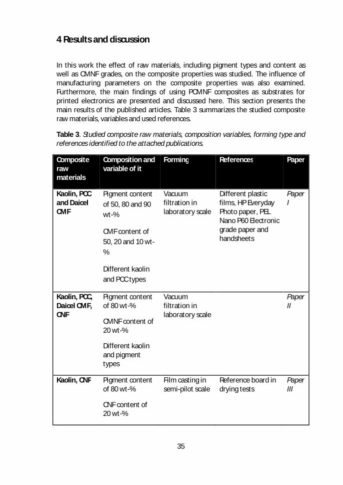
35
4 Results and discussion
In this work the effect of raw materials, including pigment types and content aswell as CMNF grades, on the composite properties was studied. The influence ofmanufacturing parameters on the composite properties was also examined.Furthermore, the main findings of using PCMNF composites as substrates forprinted electronics are presented and discussed here. This section presents themain results of the published articles. Table 3 summarizes the studied compositeraw materials, variables and used references.
Table 3. Studied composite raw materials, composition variables, forming type andreferences identified to the attached publications.
Compositerawmaterials
Composition andvariable of it
Forming References Paper
Kaolin, PCCand DaicelCMF
Pigment contentof 50, 80 and 90wt-%
CMF content of50, 20 and 10 wt-%
Different kaolinand PCC types
Vacuumfiltration inlaboratory scale
Different plasticfilms, HP EverydayPhoto paper, PELNano P60 Electronicgrade paper andhandsheets
PaperI
Kaolin, PCC,Daicel CMF,CNF
Pigment contentof 80 wt-%
CMNF content of20 wt-%
Different kaolinand pigmenttypes
Vacuumfiltration inlaboratory scale
PaperII
Kaolin, CNF Pigment contentof 80 wt-%
CNF content of20 wt-%
Film casting insemi-pilot scale
Reference board indrying tests
PaperIII
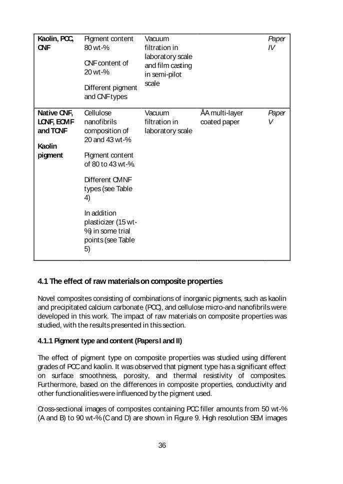
36
Kaolin, PCC,CNF
Pigment content80 wt-%
CNF content of20 wt-%
Different pigmentand CNF types
Vacuumfiltration inlaboratory scaleand film castingin semi-pilotscale
PaperIV
Native CNF,LCNF, ECMFand TCNF
Kaolinpigment
Cellulosenanofibrilscomposition of20 and 43 wt-%
Pigment contentof 80 to 43 wt-%.
Different CMNFtypes (see Table4)
In additionplasticizer (15 wt-%) in some trialpoints (see Table5)
Vacuumfiltration inlaboratory scale
ÅA multi-layercoated paper
PaperV
4.1 The effect of raw materials on composite properties
Novel composites consisting of combinations of inorganic pigments, such as kaolinand precipitated calcium carbonate (PCC), and cellulose micro-and nanofibrils weredeveloped in this work. The impact of raw materials on composite properties wasstudied, with the results presented in this section.
4.1.1 Pigment type and content (Papers I and II)
The effect of pigment type on composite properties was studied using differentgrades of PCC and kaolin. It was observed that pigment type has a significant effecton surface smoothness, porosity, and thermal resistivity of composites.Furthermore, based on the differences in composite properties, conductivity andother functionalities were influenced by the pigment used.
Cross-sectional images of composites containing PCC filler amounts from 50 wt-%(A and B) to 90 wt-% (C and D) are shown in Figure 9. High resolution SEM images
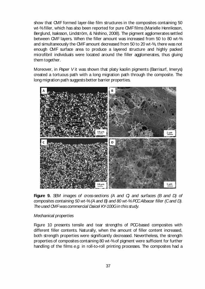
37
show that CMF formed layer-like film structures in the composites containing 50wt-% filler, which has also been reported for pure CMF films (Marielle Henriksson,Berglund, Isaksson, Lindström, & Nishino, 2008). The pigment agglomerates settledbetween CMF layers. When the filler amount was increased from 50 to 80 wt-%and simultaneously the CMF amount decreased from 50 to 20 wt-%, there was notenough CMF surface area to produce a layered structure and highly packedmicrofibril individuals were located around the filler agglomerates, thus gluingthem together.
Moreover, in Paper V it was shown that platy kaolin pigments (Barrisurf, Imerys)created a tortuous path with a long migration path through the composite. Thelong migration path suggests better barrier properties.
Figure 9. SEM images of cross-sections (A and C) and surfaces (B and D) ofcomposites containing 50 wt-% (A and B) and 80 wt-% PCC Albacar filler (C and D).The used CMF was commercial Daicel KY-100G in this study.
Mechanical properties
Figure 10 presents tensile and tear strengths of PCC-based composites withdifferent filler contents. Naturally, when the amount of filler content increased,both strength properties were significantly decreased. Nevertheless, the strengthproperties of composites containing 80 wt-% of pigment were sufficient for furtherhandling of the films e.g. in roll-to-roll printing processes. The composites had a
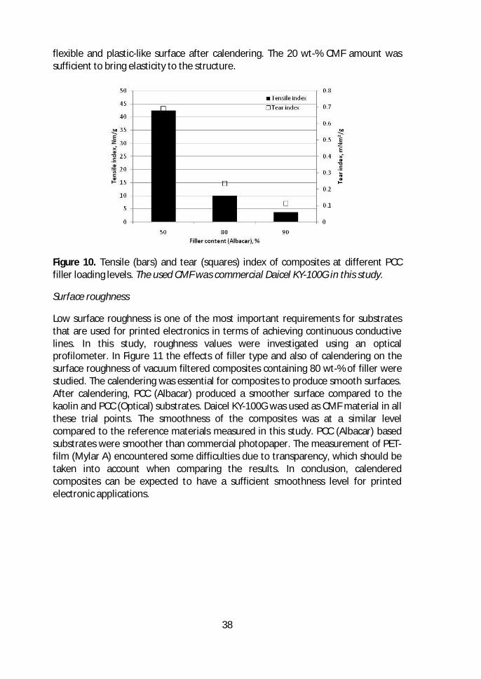
38
flexible and plastic-like surface after calendering. The 20 wt-% CMF amount wassufficient to bring elasticity to the structure.
Figure 10. Tensile (bars) and tear (squares) index of composites at different PCCfiller loading levels. The used CMF was commercial Daicel KY-100G in this study.
Surface roughness
Low surface roughness is one of the most important requirements for substratesthat are used for printed electronics in terms of achieving continuous conductivelines. In this study, roughness values were investigated using an opticalprofilometer. In Figure 11 the effects of filler type and also of calendering on thesurface roughness of vacuum filtered composites containing 80 wt-% of filler werestudied. The calendering was essential for composites to produce smooth surfaces.After calendering, PCC (Albacar) produced a smoother surface compared to thekaolin and PCC (Optical) substrates. Daicel KY-100G was used as CMF material in allthese trial points. The smoothness of the composites was at a similar levelcompared to the reference materials measured in this study. PCC (Albacar) basedsubstrates were smoother than commercial photopaper. The measurement of PET-film (Mylar A) encountered some difficulties due to transparency, which should betaken into account when comparing the results. In conclusion, calenderedcomposites can be expected to have a sufficient smoothness level for printedelectronic applications.
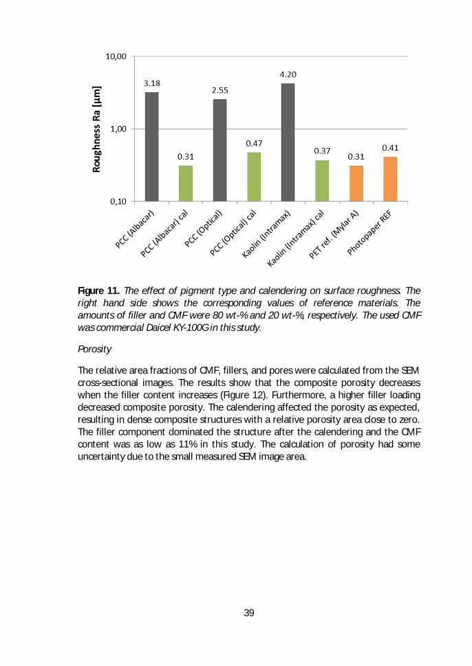
39
Figure 11. The effect of pigment type and calendering on surface roughness. Theright hand side shows the corresponding values of reference materials. Theamounts of filler and CMF were 80 wt-% and 20 wt-%, respectively. The used CMFwas commercial Daicel KY-100G in this study.
Porosity
The relative area fractions of CMF, fillers, and pores were calculated from the SEMcross-sectional images. The results show that the composite porosity decreaseswhen the filler content increases (Figure 12). Furthermore, a higher filler loadingdecreased composite porosity. The calendering affected the porosity as expected,resulting in dense composite structures with a relative porosity area close to zero.The filler component dominated the structure after the calendering and the CMFcontent was as low as 11% in this study. The calculation of porosity had someuncertainty due to the small measured SEM image area.
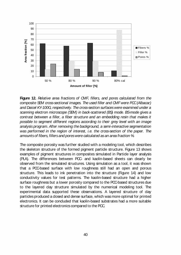
40
Figure 12. Relative area fractions of CMF, fillers, and pores calculated from thecomposite SEM cross-sectional images. The used filler and CMF were PCC (Albacar)and Daicel KY-100G, respectively. The cross-section surfaces were examined under ascanning electron microscope (SEM) in back-scattered (BS) mode. BS-mode gives acontrast between a filler, a fiber structure and an embedding resin that makes itpossible to segment different regions according to their grey level with an imageanalysis program. After removing the background, a semi-interactive segmentationwas performed in the region of interest, i.e. the cross-section of the paper. Theamounts of fibers, fillers and pores were calculated as an area fraction %.
The composite porosity was further studied with a modeling tool, which describesthe skeleton structure of the formed pigment particle structure. Figure 13 showsexamples of pigment structures in composites simulated in Particle layer analysis(PLA). The differences between PCC- and kaolin-based sheets can clearly beobserved from the simulated structures. Using simulation as a tool, it was shownthat a PCC-based surface with low roughness still had an open and porousstructure. This leads to ink penetration into the structure (Figure 14) and lowconductivity values for test patterns. The kaolin-based structure had a highersurface roughness but a lower porosity compared to the PCC-based structures dueto the layered clay structure simulated by the numerical modeling tool. Theexperimental data supported these observations. A layered structure of clayparticles produced a closed and dense surface, which was more optimal for printedelectronics. It can be concluded that kaolin-based substrates had a more suitablestructure for printed electronics compared to the PCC.
0
10
20
30
40
50
60
70
80
90
100
50 % 80 % 90 % 80% cal
Amount of filler [%]
Area
fract
ion
[%]
Fibers %
Filler %
Pores %
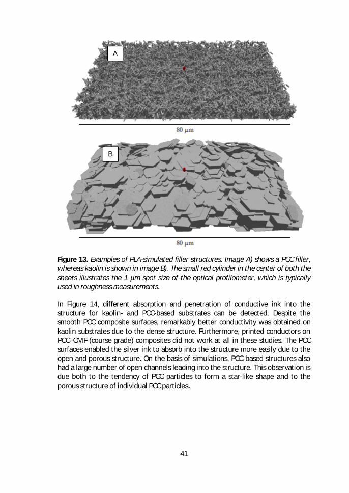
41
Figure 13. Examples of PLA-simulated filler structures. Image A) shows a PCC filler,whereas kaolin is shown in image B). The small red cylinder in the center of both thesheets illustrates the 1 µm spot size of the optical profilometer, which is typicallyused in roughness measurements.
In Figure 14, different absorption and penetration of conductive ink into thestructure for kaolin- and PCC-based substrates can be detected. Despite thesmooth PCC composite surfaces, remarkably better conductivity was obtained onkaolin substrates due to the dense structure. Furthermore, printed conductors onPCC–CMF (course grade) composites did not work at all in these studies. The PCCsurfaces enabled the silver ink to absorb into the structure more easily due to theopen and porous structure. On the basis of simulations, PCC-based structures alsohad a large number of open channels leading into the structure. This observation isdue both to the tendency of PCC particles to form a star-like shape and to theporous structure of individual PCC particles.
A
B
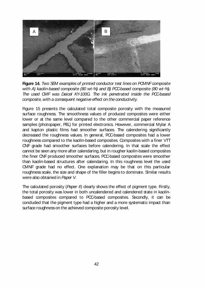
42
Figure 14. Two SEM examples of printed conductor test lines on PCMNF compositewith A) kaolin-based composite (80 wt-%) and B) PCC-based composite (80 wt-%).The used CMF was Daicel KY-100G. The ink penetrated inside the PCC-basedcomposite, with a consequent negative effect on the conductivity.
Figure 15 presents the calculated total composite porosity with the measuredsurface roughness. The smoothness values of produced composites were eitherlower or at the same level compared to the other commercial paper referencesamples (photopaper, PEL) for printed electronics. However, commercial Mylar Aand kapton plastic films had smoother surfaces. The calendering significantlydecreased the roughness values. In general, PCC-based composites had a lowerroughness compared to the kaolin-based composites. Composites with a finer VTTCNF grade had smoother surfaces before calendering. In that scale the effectcannot be seen any more after calendaring, but in rougher kaolin-based compositesthe finer CNF produced smoother surfaces. PCC-based composites were smootherthan kaolin-based structures after calendaring. In this roughness level the usedCMNF grade had no effect. One explanation may be that on this particularroughness scale, the size and shape of the filler begins to dominate. Similar resultswere also obtained in Paper V.
The calculated porosity (Paper II) clearly shows the effect of pigment type. Firstly,the total porosity was lower in both uncalendered and calendered state in kaolin-based composites compared to PCC-based composites. Secondly, it can beconcluded that the pigment type had a higher and a more systematic impact thansurface roughness on the achieved composite porosity level.
A B
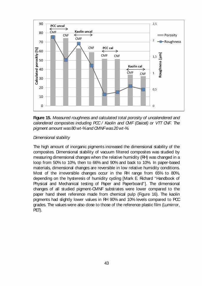
43
Figure 15. Measured roughness and calculated total porosity of uncalendered andcalendered composites including PCC / Kaolin and CMF (Daicel) or VTT CNF. Thepigment amount was 80 wt-% and CMNF was 20 wt-%.
Dimensional stability
The high amount of inorganic pigments increased the dimensional stability of thecomposites. Dimensional stability of vacuum filtered composites was studied bymeasuring dimensional changes when the relative humidity (RH) was changed in aloop from 50% to 10%, then to 66% and 90% and back to 10%. In paper-basedmaterials, dimensional changes are reversible in low relative humidity conditions.Most of the irreversible changes occur in the RH range from 65% to 80%,depending on the hysteresis of humidity cycling [Mark E. Richard “Handbook ofPhysical and Mechanical testing of Paper and Paperboard”]. The dimensionalchanges of all studied pigment-CMNF substrates were lower compared to thepaper hand sheet reference made from chemical pulp (Figure 16). The kaolinpigments had slightly lower values in RH 90% and 10% levels compared to PCCgrades. The values were also close to those of the reference plastic film (Lumirror,PET).
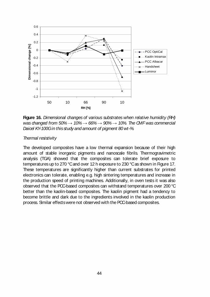
44
Figure 16. Dimensional changes of various substrates when relative humidity (RH)was changed from 50% → 10% → 66% → 90% → 10%. The CMF was commercialDaicel KY-100G in this study and amount of pigment 80 wt-%.
Thermal resistivity
The developed composites have a low thermal expansion because of their highamount of stable inorganic pigments and nanoscale fibrils. Thermogravimetricanalysis (TGA) showed that the composites can tolerate brief exposure totemperatures up to 270 °C and over 12 h exposure to 230 °C as shown in Figure 17.These temperatures are significantly higher than current substrates for printedelectronics can tolerate, enabling e.g. high sintering temperatures and increase inthe production speed of printing machines. Additionally, in oven tests it was alsoobserved that the PCC-based composites can withstand temperatures over 200 °Cbetter than the kaolin-based composites. The kaolin pigment had a tendency tobecome brittle and dark due to the ingredients involved in the kaolin productionprocess. Similar effects were not observed with the PCC-based composites.
-1.2
-1
-0.8
-0.6
-0.4
-0.2
0
0.2
0.4
0.6
50 10 66 90 10RH [%]
Dim
ensi
onal
chan
ge[%
]
PCC OptiCalKaolin IntramaxPCC AlbacarHandsheetLumirror
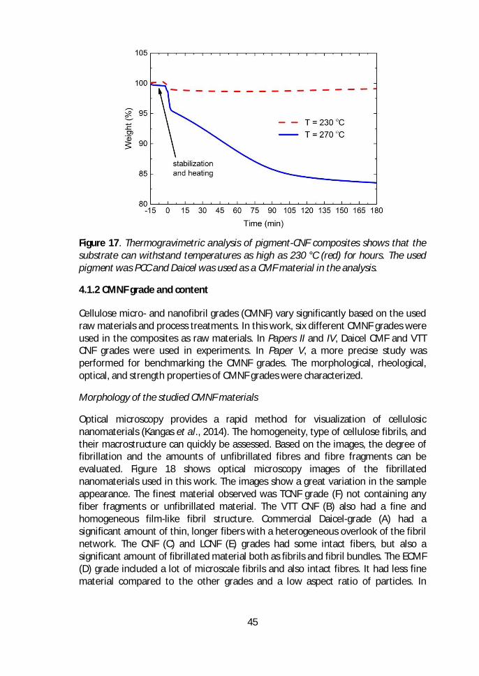
45
Figure 17. Thermogravimetric analysis of pigment-CNF composites shows that thesubstrate can withstand temperatures as high as 230 °C (red) for hours. The usedpigment was PCC and Daicel was used as a CMF material in the analysis.
4.1.2 CMNF grade and content
Cellulose micro- and nanofibril grades (CMNF) vary significantly based on the usedraw materials and process treatments. In this work, six different CMNF grades wereused in the composites as raw materials. In Papers II and IV, Daicel CMF and VTTCNF grades were used in experiments. In Paper V, a more precise study wasperformed for benchmarking the CMNF grades. The morphological, rheological,optical, and strength properties of CMNF grades were characterized.
Morphology of the studied CMNF materials
Optical microscopy provides a rapid method for visualization of cellulosicnanomaterials (Kangas et al., 2014). The homogeneity, type of cellulose fibrils, andtheir macrostructure can quickly be assessed. Based on the images, the degree offibrillation and the amounts of unfibrillated fibres and fibre fragments can beevaluated. Figure 18 shows optical microscopy images of the fibrillatednanomaterials used in this work. The images show a great variation in the sampleappearance. The finest material observed was TCNF grade (F) not containing anyfiber fragments or unfibrillated material. The VTT CNF (B) also had a fine andhomogeneous film-like fibril structure. Commercial Daicel-grade (A) had asignificant amount of thin, longer fibers with a heterogeneous overlook of the fibrilnetwork. The CNF (C) and LCNF (E) grades had some intact fibers, but also asignificant amount of fibrillated material both as fibrils and fibril bundles. The ECMF(D) grade included a lot of microscale fibrils and also intact fibres. It had less finematerial compared to the other grades and a low aspect ratio of particles. In
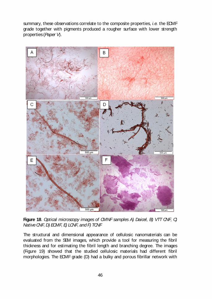
46
summary, these observations correlate to the composite properties, i.e. the ECMFgrade together with pigments produced a rougher surface with lower strengthproperties (Paper V).
Figure 18. Optical microscopy images of CMNF samples A) Daicel, B) VTT CNF, C)Native CNF, D) ECMF, E) LCNF, and F) TCNF
The structural and dimensional appearance of cellulosic nanomaterials can beevaluated from the SEM images, which provide a tool for measuring the fibrilthickness and for estimating the fibril length and branching degree. The images(Figure 19) showed that the studied cellulosic materials had different fibrilmorphologies. The ECMF grade (D) had a bulky and porous fibrillar network with
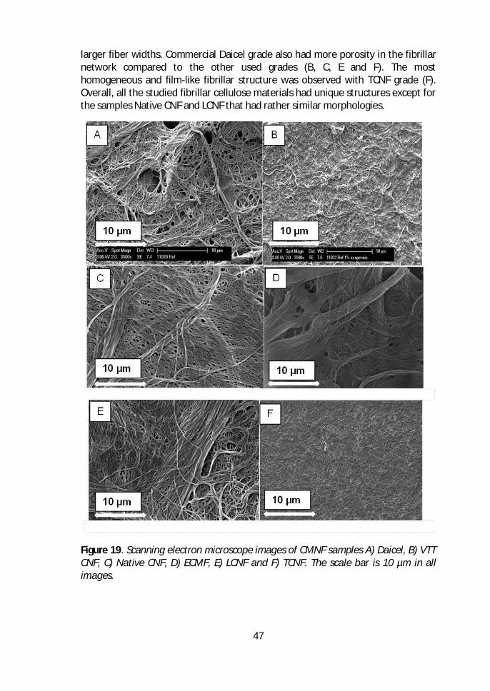
47
larger fiber widths. Commercial Daicel grade also had more porosity in the fibrillarnetwork compared to the other used grades (B, C, E and F). The mosthomogeneous and film-like fibrillar structure was observed with TCNF grade (F).Overall, all the studied fibrillar cellulose materials had unique structures except forthe samples Native CNF and LCNF that had rather similar morphologies.
Figure 19. Scanning electron microscope images of CMNF samples A) Daicel, B) VTTCNF, C) Native CNF, D) ECMF, E) LCNF and F) TCNF. The scale bar is 10 µm in allimages.
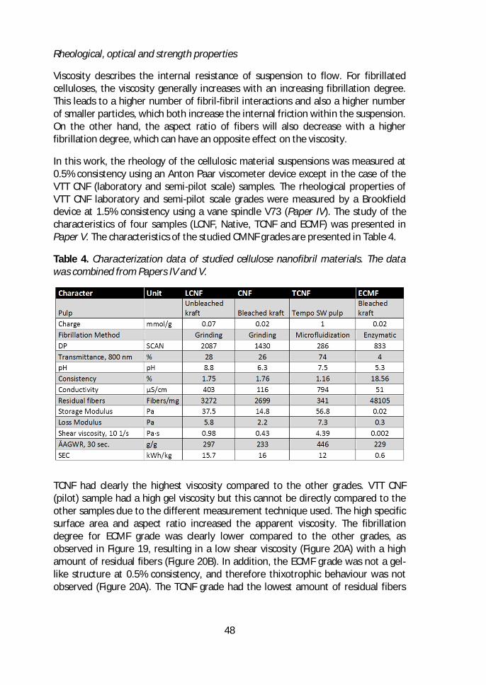
48
Rheological, optical and strength properties
Viscosity describes the internal resistance of suspension to flow. For fibrillatedcelluloses, the viscosity generally increases with an increasing fibrillation degree.This leads to a higher number of fibril-fibril interactions and also a higher numberof smaller particles, which both increase the internal friction within the suspension.On the other hand, the aspect ratio of fibers will also decrease with a higherfibrillation degree, which can have an opposite effect on the viscosity.
In this work, the rheology of the cellulosic material suspensions was measured at0.5% consistency using an Anton Paar viscometer device except in the case of theVTT CNF (laboratory and semi-pilot scale) samples. The rheological properties ofVTT CNF laboratory and semi-pilot scale grades were measured by a Brookfielddevice at 1.5% consistency using a vane spindle V73 (Paper IV). The study of thecharacteristics of four samples (LCNF, Native, TCNF and ECMF) was presented inPaper V. The characteristics of the studied CMNF grades are presented in Table 4.
Table 4. Characterization data of studied cellulose nanofibril materials. The datawas combined from Papers IV and V.
TCNF had clearly the highest viscosity compared to the other grades. VTT CNF(pilot) sample had a high gel viscosity but this cannot be directly compared to theother samples due to the different measurement technique used. The high specificsurface area and aspect ratio increased the apparent viscosity. The fibrillationdegree for ECMF grade was clearly lower compared to the other grades, asobserved in Figure 19, resulting in a low shear viscosity (Figure 20A) with a highamount of residual fibers (Figure 20B). In addition, the ECMF grade was not a gel-like structure at 0.5% consistency, and therefore thixotrophic behaviour was notobserved (Figure 20A). The TCNF grade had the lowest amount of residual fibers
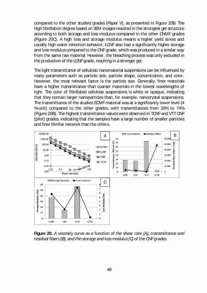
49
compared to the other studied grades (Paper V), as presented in Figure 20B. Thehigh fibrillation degree based on SEM images resulted in the strongest gel structureaccording to both storage and loss modulus compared to the other CNMF grades(Figure 20C). A high loss and storage modulus means a higher yield stress andusually high water retention behavior. LCNF also had a significantly higher storageand loss modulus compared to the CNF grade, which was produced in a similar wayfrom the same raw material. However, the bleaching process was only excluded inthe production of the LCNF grade, resulting in a stronger gel.
The light transmittance of cellulosic nanomaterial suspensions can be influenced bymany parameters such as particle size, particle shape, concentration, and color.However, the most relevant factor is the particle size. Generally, finer materialshave a higher transmittance than coarser materials in the lowest wavelengths oflight. The color of fibrillated cellulose suspensions is white or opaque, indicatingthat they contain larger nanoparticles than, for example, nanocrystal suspensions.The transmittance of the studied ECMF material was at a significantly lower level (4%-unit) compared to the other grades, with transmittances from 26% to 74%(Figure 20B). The highest transmittance values were observed in TCNF and VTT CNF(pilot) grades, indicating that the samples have a large number of smaller particlesand finer fibrillar network than the others.
Figure 20. A viscosity curve as a function of the shear rate (A), transmittance andresidual fibers (B), and the storage and loss modulus (C) of the CNF grades.
A B
C
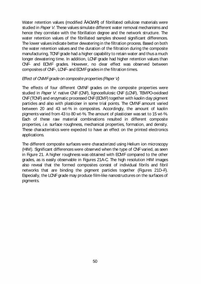
50
Water retention values (modified ÅAGWR) of fibrillated cellulose materials werestudied in Paper V. These values simulate different water removal mechanisms andhence they correlate with the fibrillation degree and the network structure. Thewater retention values of the fibrillated samples showed significant differences.The lower values indicate better dewatering in the filtration process. Based on boththe water retention values and the duration of the filtration during the compositemanufacturing, TCNF grade had a higher capability to retain water and thus a muchlonger dewatering time. In addition, LCNF grade had higher retention values thanCNF- and ECMF grades. However, no clear effect was observed betweencomposites of CNF-, LCNF- and ECMF grades in the filtration times.
Effect of CNMF grade on composite properties (Paper V)
The effects of four different CMNF grades on the composite properties werestudied in Paper V: native CNF (CNF), lignocellulosic CNF (LCNF), TEMPO-oxidisedCNF (TCNF) and enzymatic processed CNF (ECMF) together with kaolin clay pigmentparticles and also with plasticiser in some trial points. The CMNF amount variedbetween 20 and 43 wt-% in composites. Accordingly, the amount of kaolinpigments varied from 43 to 80 wt-%. The amount of plasticiser was set to 15 wt-%.Each of these raw material combinations resulted in different compositeproperties, i.e. surface roughness, mechanical properties, formation, and density.These characteristics were expected to have an effect on the printed electronicsapplications.
The different composite surfaces were characterized using Helium ion microscopy(HIM). Significant differences were observed when the type of CNF varied, as seenin Figure 21. A higher roughness was obtained with ECMF compared to the othergrades, as is easily observable in Figures 21A-C. The high resolution HIM imagesalso reveal that the formed composites consist of individual fibrils and fibrilnetworks that are binding the pigment particles together (Figures 21D–F).Especially, the LCNF grade may produce film-like nanostructures on the surfaces ofpigments.
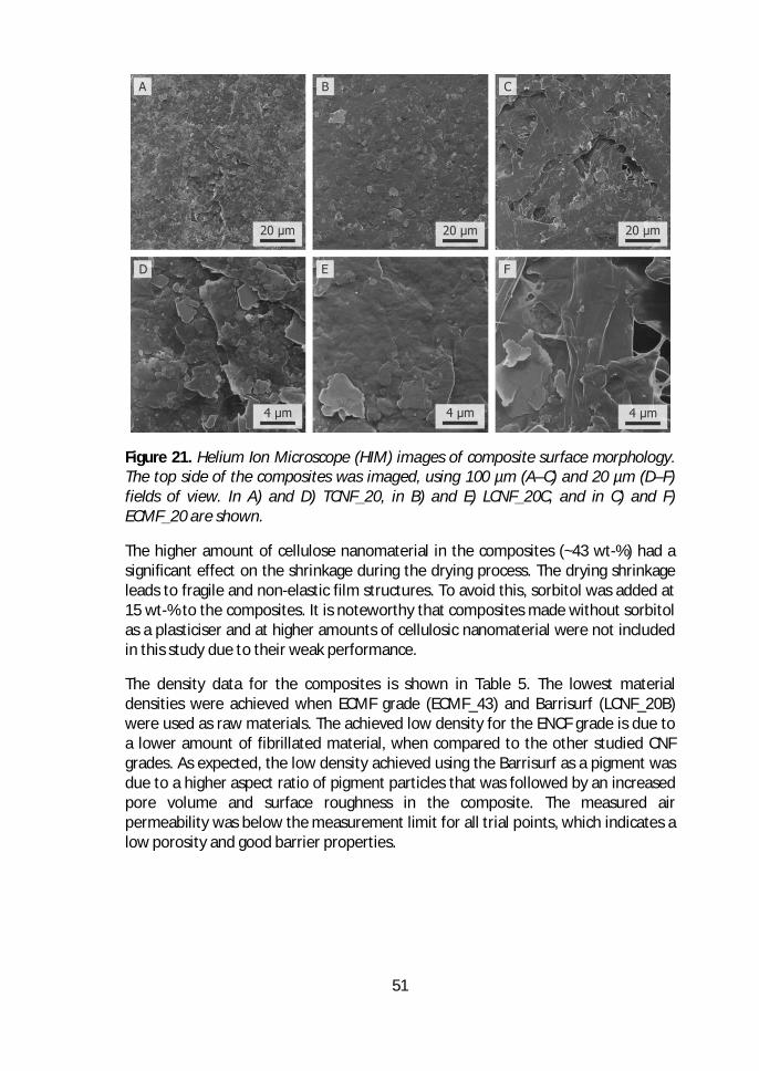
51
Figure 21. Helium Ion Microscope (HIM) images of composite surface morphology.The top side of the composites was imaged, using 100 µm (A–C) and 20 µm (D–F)fields of view. In A) and D) TCNF_20, in B) and E) LCNF_20C, and in C) and F)ECMF_20 are shown.
The higher amount of cellulose nanomaterial in the composites (~43 wt-%) had asignificant effect on the shrinkage during the drying process. The drying shrinkageleads to fragile and non-elastic film structures. To avoid this, sorbitol was added at15 wt-% to the composites. It is noteworthy that composites made without sorbitolas a plasticiser and at higher amounts of cellulosic nanomaterial were not includedin this study due to their weak performance.
The density data for the composites is shown in Table 5. The lowest materialdensities were achieved when ECMF grade (ECMF_43) and Barrisurf (LCNF_20B)were used as raw materials. The achieved low density for the ENCF grade is due toa lower amount of fibrillated material, when compared to the other studied CNFgrades. As expected, the low density achieved using the Barrisurf as a pigment wasdue to a higher aspect ratio of pigment particles that was followed by an increasedpore volume and surface roughness in the composite. The measured airpermeability was below the measurement limit for all trial points, which indicates alow porosity and good barrier properties.
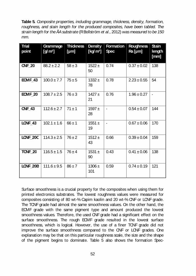
52
Table 5. Composite properties, including grammage, thickness, density, formation,roughness, and stain length for the produced composites, have been tabled. Thestrain length for the ÅA substrate (R Bollström et al., 2012) was measured to be 150mm.
Trialpoint
Grammage[g/m²]
Thickness[µm]
Density[kg/m³]
FormationSpec
RoughnessRa [µm]
Stainlength[mm]
CNF_20 88.2 ± 2.2 58 ± 3 1522 ±50
0.74 0.37 ± 0.02 138
ECMF_43 100.0 ± 7.7 75 ± 5 1332 ±78
0.78 2.23 ± 0.55 54
ECMF_20 108.7 ± 2.5 76 ± 3 1427 ±21
0.76 1.96 ± 0.27 -
CNF_43 112.6 ± 2.7 71 ± 1 1597 ±28
- 0.54 ± 0.07 144
LCNF_43 102.1 ± 1.6 66 ± 1 1551 ±19
- 0.67 ± 0.06 170
LCNF_20C 114.3 ± 2.5 76 ± 2 1512 ±43
0.66 0.39 ± 0.04 159
TCNF_20 116.5 ± 1.5 76 ± 4 1531 ±90
0.43 0.41 ± 0.06 138
LCNF_20B 111.6 ± 9.5 86 ± 7 1306 ±101
0.59 0.74 ± 0.19 121
Surface smoothness is a crucial property for the composites when using them forprinted electronics substrates. The lowest roughness values were measured forcomposites consisting of 80 wt-% Capim kaolin and 20 wt-% CNF or LCNF grade.The TCNF grade had almost the same smoothness values. On the other hand, theECMF grade with the same pigment type and amount produced the lowestsmoothness values. Therefore, the used CNF grade had a significant effect on thesurface smoothness. The rough ECMF grade resulted in the lowest surfacesmoothness, which is logical. However, the use of a finer TCNF grade did notimprove the surface smoothness compared to the CNF or LCNF grades. Oneexplanation may be that on this particular roughness scale, the size and the shapeof the pigment begins to dominate. Table 5 also shows the formation Spec-
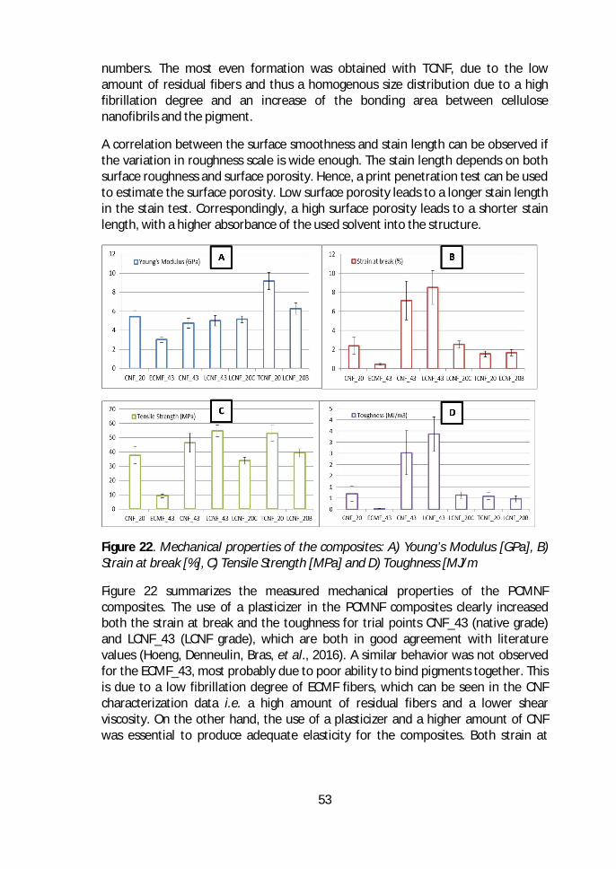
53
numbers. The most even formation was obtained with TCNF, due to the lowamount of residual fibers and thus a homogenous size distribution due to a highfibrillation degree and an increase of the bonding area between cellulosenanofibrils and the pigment.
A correlation between the surface smoothness and stain length can be observed ifthe variation in roughness scale is wide enough. The stain length depends on bothsurface roughness and surface porosity. Hence, a print penetration test can be usedto estimate the surface porosity. Low surface porosity leads to a longer stain lengthin the stain test. Correspondingly, a high surface porosity leads to a shorter stainlength, with a higher absorbance of the used solvent into the structure.
Figure 22. Mechanical properties of the composites: A) Young’s Modulus [GPa], B)Strain at break [%], C) Tensile Strength [MPa] and D) Toughness [MJ/m
Figure 22 summarizes the measured mechanical properties of the PCMNFcomposites. The use of a plasticizer in the PCMNF composites clearly increasedboth the strain at break and the toughness for trial points CNF_43 (native grade)and LCNF_43 (LCNF grade), which are both in good agreement with literaturevalues (Hoeng, Denneulin, Bras, et al., 2016). A similar behavior was not observedfor the ECMF_43, most probably due to poor ability to bind pigments together. Thisis due to a low fibrillation degree of ECMF fibers, which can be seen in the CNFcharacterization data i.e. a high amount of residual fibers and a lower shearviscosity. On the other hand, the use of a plasticizer and a higher amount of CNFwas essential to produce adequate elasticity for the composites. Both strain at
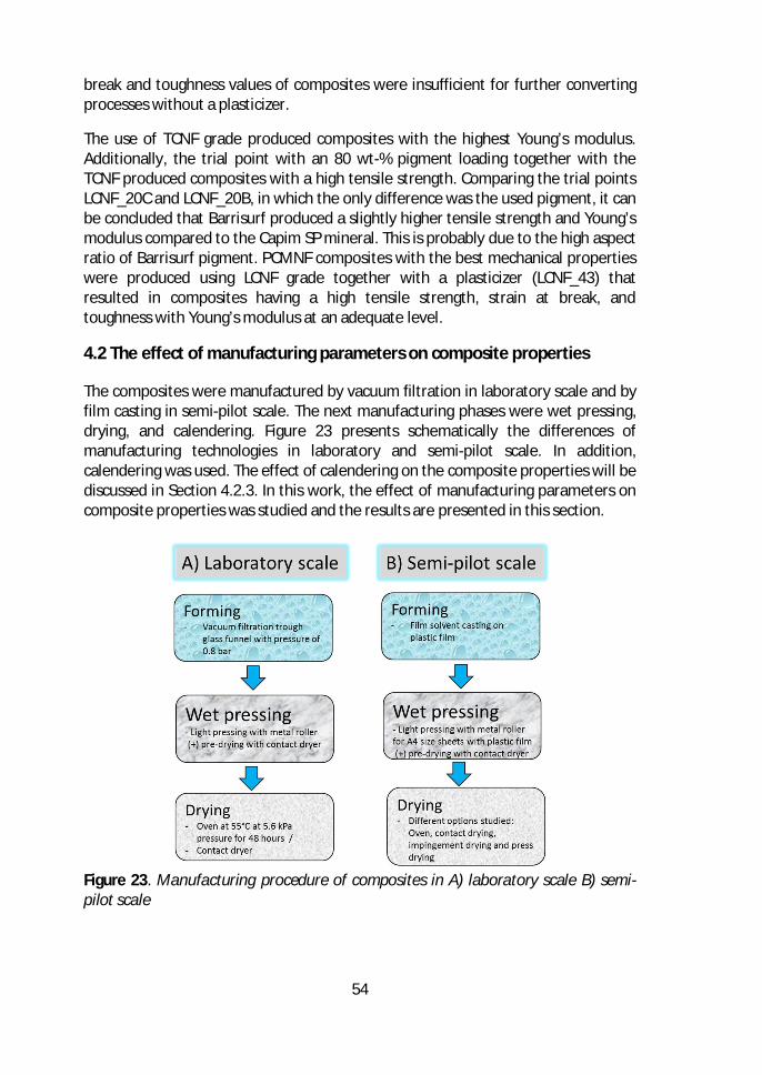
54
break and toughness values of composites were insufficient for further convertingprocesses without a plasticizer.
The use of TCNF grade produced composites with the highest Young’s modulus.Additionally, the trial point with an 80 wt-% pigment loading together with theTCNF produced composites with a high tensile strength. Comparing the trial pointsLCNF_20C and LCNF_20B, in which the only difference was the used pigment, it canbe concluded that Barrisurf produced a slightly higher tensile strength and Young’smodulus compared to the Capim SP mineral. This is probably due to the high aspectratio of Barrisurf pigment. PCMNF composites with the best mechanical propertieswere produced using LCNF grade together with a plasticizer (LCNF_43) thatresulted in composites having a high tensile strength, strain at break, andtoughness with Young’s modulus at an adequate level.
4.2 The effect of manufacturing parameters on composite properties
The composites were manufactured by vacuum filtration in laboratory scale and byfilm casting in semi-pilot scale. The next manufacturing phases were wet pressing,drying, and calendering. Figure 23 presents schematically the differences ofmanufacturing technologies in laboratory and semi-pilot scale. In addition,calendering was used. The effect of calendering on the composite properties will bediscussed in Section 4.2.3. In this work, the effect of manufacturing parameters oncomposite properties was studied and the results are presented in this section.
Figure 23. Manufacturing procedure of composites in A) laboratory scale B) semi-pilot scale
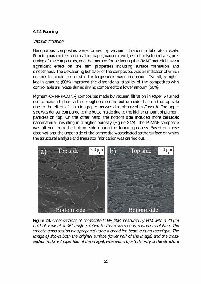
55
4.2.1 Forming
Vacuum filtration
Nanoporous composites were formed by vacuum filtration in laboratory scale.Forming parameters such as filter paper, vacuum level, use of polyelectrolytes, pre-drying of the composites, and the method for activating the CMNF material have asignificant effect on the film properties including surface formation andsmoothness. The dewatering behavior of the composites was an indicator of whichcomposites could be suitable for large-scale mass production. Overall, a higherkaolin amount (80%) improved the dimensional stability of the composites withcontrollable shrinkage during drying compared to a lower amount (50%).
Pigment-CMNF (PCMNF) composites made by vacuum filtration in Paper V turnedout to have a higher surface roughness on the bottom side than on the top sidedue to the effect of filtration paper, as was also observed in Paper II. The upperside was denser compared to the bottom side due to the higher amount of pigmentparticles on top. On the other hand, the bottom side included more cellulosicnanomaterial, resulting in a higher porosity (Figure 24A). The PCMNF compositewas filtered from the bottom side during the forming process. Based on theseobservations, the upper side of the composite was selected as the surface on whichthe structural analysis and transistor fabrication was carried out.
Figure 24. Cross-sections of composite LCNF_20B measured by HIM with a 20 µmfield of view at a 45˚ angle relative to the cross-section surface resolution. Thesmooth cross-section was prepared using a broad ion beam cutting technique. Theimage a) shows both the original surface (lower half of the image) and the cross-section surface (upper half of the image), whereas in b) a tortuosity of the structure
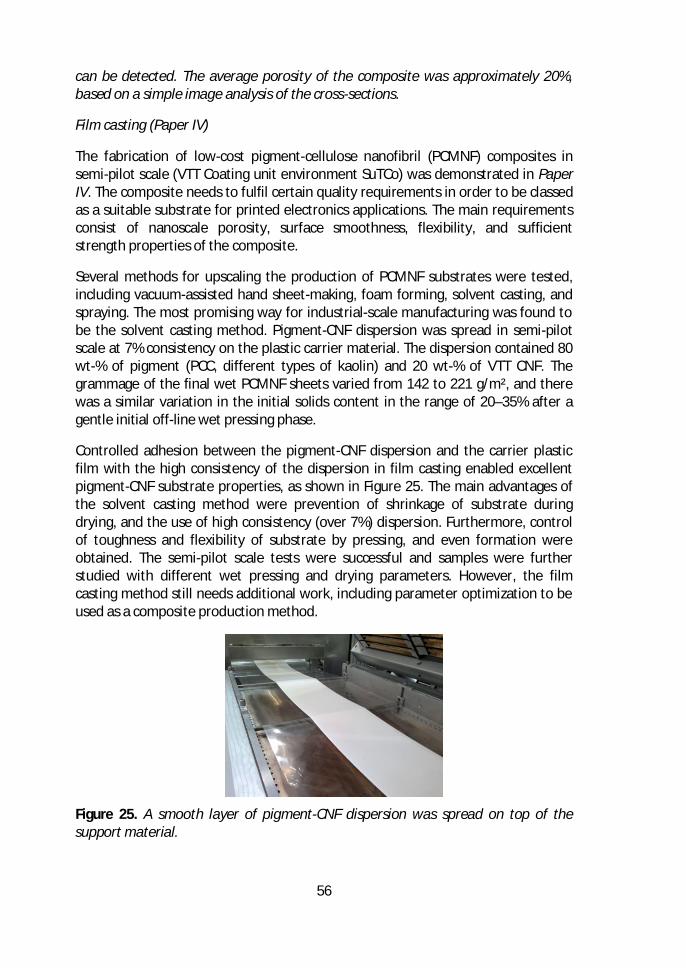
56
can be detected. The average porosity of the composite was approximately 20%,based on a simple image analysis of the cross-sections.
Film casting (Paper IV)
The fabrication of low-cost pigment-cellulose nanofibril (PCMNF) composites insemi-pilot scale (VTT Coating unit environment SuTCo) was demonstrated in PaperIV. The composite needs to fulfil certain quality requirements in order to be classedas a suitable substrate for printed electronics applications. The main requirementsconsist of nanoscale porosity, surface smoothness, flexibility, and sufficientstrength properties of the composite.
Several methods for upscaling the production of PCMNF substrates were tested,including vacuum-assisted hand sheet-making, foam forming, solvent casting, andspraying. The most promising way for industrial-scale manufacturing was found tobe the solvent casting method. Pigment-CNF dispersion was spread in semi-pilotscale at 7% consistency on the plastic carrier material. The dispersion contained 80wt-% of pigment (PCC, different types of kaolin) and 20 wt-% of VTT CNF. Thegrammage of the final wet PCMNF sheets varied from 142 to 221 g/m², and therewas a similar variation in the initial solids content in the range of 20–35% after agentle initial off-line wet pressing phase.
Controlled adhesion between the pigment-CNF dispersion and the carrier plasticfilm with the high consistency of the dispersion in film casting enabled excellentpigment-CNF substrate properties, as shown in Figure 25. The main advantages ofthe solvent casting method were prevention of shrinkage of substrate duringdrying, and the use of high consistency (over 7%) dispersion. Furthermore, controlof toughness and flexibility of substrate by pressing, and even formation wereobtained. The semi-pilot scale tests were successful and samples were furtherstudied with different wet pressing and drying parameters. However, the filmcasting method still needs additional work, including parameter optimization to beused as a composite production method.
Figure 25. A smooth layer of pigment-CNF dispersion was spread on top of thesupport material.
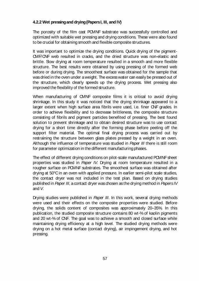
57
4.2.2 Wet pressing and drying (Papers I, III, and IV)
The porosity of the film cast PCMNF substrate was successfully controlled andoptimized with suitable wet pressing and drying conditions. These were also foundto be crucial for obtaining smooth and flexible composite structures.
It was important to optimize the drying conditions. Quick drying of the pigment-CMF/CNF web resulted in cracks, and the dried structure was non-elastic andbrittle. Slow drying at room temperature resulted in a smooth and more flexiblestructure. The best results were obtained by using pressing of the formed webbefore or during drying. The smoothest surface was obtained for the sample thatwas dried in the oven under a weight. The excess water can easily be pressed out ofthe structure, which clearly speeds up the drying process. Wet pressing alsoimproved the flexibility of the formed structure.
When manufacturing of CMNF composite films it is critical to avoid dryingshrinkage. In this study it was noticed that the drying shrinkage appeared to alarger extent when high surface area fibrils were used, i.e. finer CNF grades. Inorder to achieve flexibility and to decrease brittleness, the composite structureconsisting of fibrils and pigment particles benefited of pressing. The best foundsolution to prevent shrinkage and to obtain desired structure was to use contactdrying for a short time directly after the forming phase before peeling off thesupport filter material. The optimal final drying process was carried out byrestraining the structure between glass plates pressed by a weight in an oven.Although the influence of temperature was studied in Paper III there is still roomfor parameter optimization in the different manufacturing phases.
The effect of different drying conditions on pilot-scale manufactured PCMNF sheetproperties was studied in Paper IV. Drying at room temperature resulted in arougher surface on PCMNF substrates. The smoothest surface was obtained afterdrying at 50°C in an oven with applied pressure. In earlier semi-pilot scale studies,the contact dryer was not included in the test plan. Based on drying studiespublished in Paper III, a contact dryer was chosen as the drying method in Papers IVand V.
Drying studies were published in Paper III. In this work, several drying methodswere used and their effects on the composite properties were studied. Beforedrying, the solids content of composites was approximately 20–35%. In thispublication, the studied composite structure contains 80 wt-% of kaolin pigmentsand 20 wt-% of CNF. The goal was to achieve a smooth and closed surface whilemaintaining drying efficiency at a high level. The studied drying methods weredrying on a hot metal surface (contact drying), air impingement drying, and hotpressing.
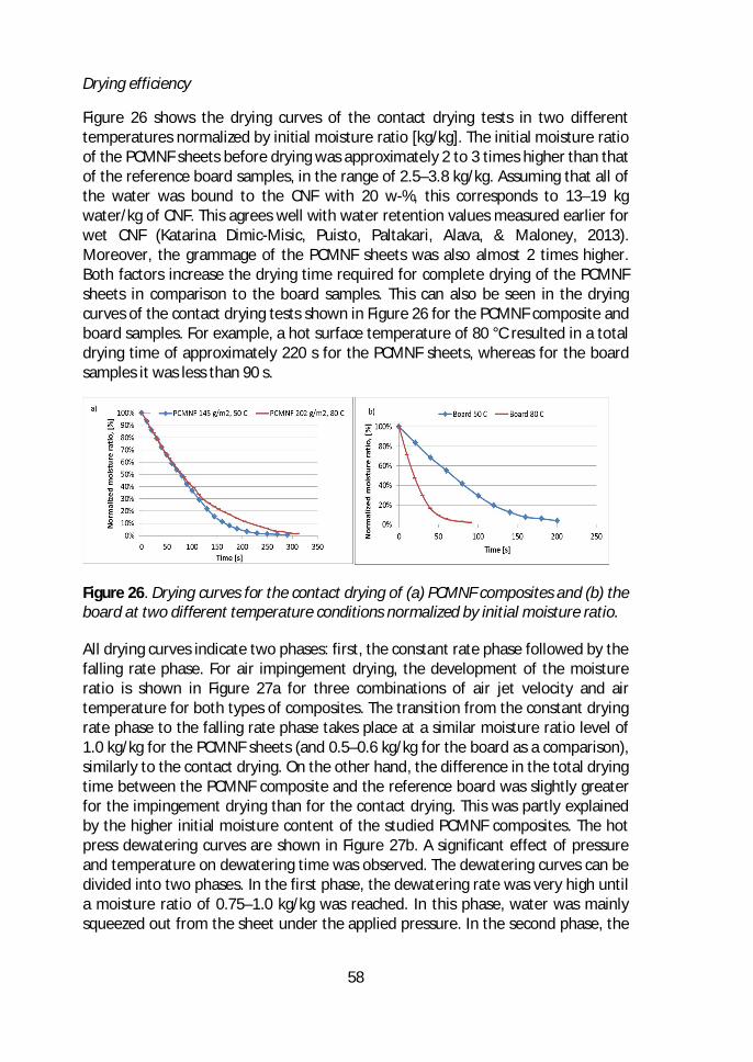
58
Drying efficiency
Figure 26 shows the drying curves of the contact drying tests in two differenttemperatures normalized by initial moisture ratio [kg/kg]. The initial moisture ratioof the PCMNF sheets before drying was approximately 2 to 3 times higher than thatof the reference board samples, in the range of 2.5–3.8 kg/kg. Assuming that all ofthe water was bound to the CNF with 20 w-%, this corresponds to 13–19 kgwater/kg of CNF. This agrees well with water retention values measured earlier forwet CNF (Katarina Dimic-Misic, Puisto, Paltakari, Alava, & Maloney, 2013).Moreover, the grammage of the PCMNF sheets was also almost 2 times higher.Both factors increase the drying time required for complete drying of the PCMNFsheets in comparison to the board samples. This can also be seen in the dryingcurves of the contact drying tests shown in Figure 26 for the PCMNF composite andboard samples. For example, a hot surface temperature of 80 °C resulted in a totaldrying time of approximately 220 s for the PCMNF sheets, whereas for the boardsamples it was less than 90 s.
Figure 26. Drying curves for the contact drying of (a) PCMNF composites and (b) theboard at two different temperature conditions normalized by initial moisture ratio.
All drying curves indicate two phases: first, the constant rate phase followed by thefalling rate phase. For air impingement drying, the development of the moistureratio is shown in Figure 27a for three combinations of air jet velocity and airtemperature for both types of composites. The transition from the constant dryingrate phase to the falling rate phase takes place at a similar moisture ratio level of1.0 kg/kg for the PCMNF sheets (and 0.5–0.6 kg/kg for the board as a comparison),similarly to the contact drying. On the other hand, the difference in the total dryingtime between the PCMNF composite and the reference board was slightly greaterfor the impingement drying than for the contact drying. This was partly explainedby the higher initial moisture content of the studied PCMNF composites. The hotpress dewatering curves are shown in Figure 27b. A significant effect of pressureand temperature on dewatering time was observed. The dewatering curves can bedivided into two phases. In the first phase, the dewatering rate was very high untila moisture ratio of 0.75–1.0 kg/kg was reached. In this phase, water was mainlysqueezed out from the sheet under the applied pressure. In the second phase, the
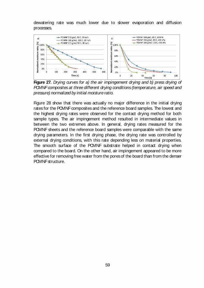
59
dewatering rate was much lower due to slower evaporation and diffusionprocesses.
Figure 27. Drying curves for a) the air impingement drying and b) press drying ofPCMNF composites at three different drying conditions (temperature, air speed andpressure) normalized by initial moisture ratio.
Figure 28 show that there was actually no major difference in the initial dryingrates for the PCMNF composites and the reference board samples. The lowest andthe highest drying rates were observed for the contact drying method for bothsample types. The air impingement method resulted in intermediate values inbetween the two extremes above. In general, drying rates measured for thePCMNF sheets and the reference board samples were comparable with the samedrying parameters. In the first drying phase, the drying rate was controlled byexternal drying conditions, with this rate depending less on material properties.The smooth surface of the PCMNF substrate helped in contact drying whencompared to the board. On the other hand, air impingement appeared to be moreeffective for removing free water from the pores of the board than from the denserPCMNF structure.
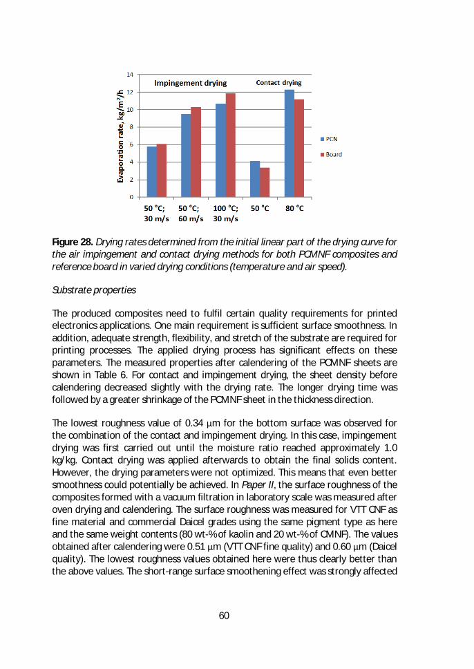
60
Figure 28. Drying rates determined from the initial linear part of the drying curve forthe air impingement and contact drying methods for both PCMNF composites andreference board in varied drying conditions (temperature and air speed).
Substrate properties
The produced composites need to fulfil certain quality requirements for printedelectronics applications. One main requirement is sufficient surface smoothness. Inaddition, adequate strength, flexibility, and stretch of the substrate are required forprinting processes. The applied drying process has significant effects on theseparameters. The measured properties after calendering of the PCMNF sheets areshown in Table 6. For contact and impingement drying, the sheet density beforecalendering decreased slightly with the drying rate. The longer drying time wasfollowed by a greater shrinkage of the PCMNF sheet in the thickness direction.
The lowest roughness value of 0.34 μm for the bottom surface was observed forthe combination of the contact and impingement drying. In this case, impingementdrying was first carried out until the moisture ratio reached approximately 1.0kg/kg. Contact drying was applied afterwards to obtain the final solids content.However, the drying parameters were not optimized. This means that even bettersmoothness could potentially be achieved. In Paper II, the surface roughness of thecomposites formed with a vacuum filtration in laboratory scale was measured afteroven drying and calendering. The surface roughness was measured for VTT CNF asfine material and commercial Daicel grades using the same pigment type as hereand the same weight contents (80 wt-% of kaolin and 20 wt-% of CMNF). The valuesobtained after calendering were 0.51 μm (VTT CNF fine quality) and 0.60 μm (Daicelquality). The lowest roughness values obtained here were thus clearly better thanthe above values. The short-range surface smoothening effect was strongly affected
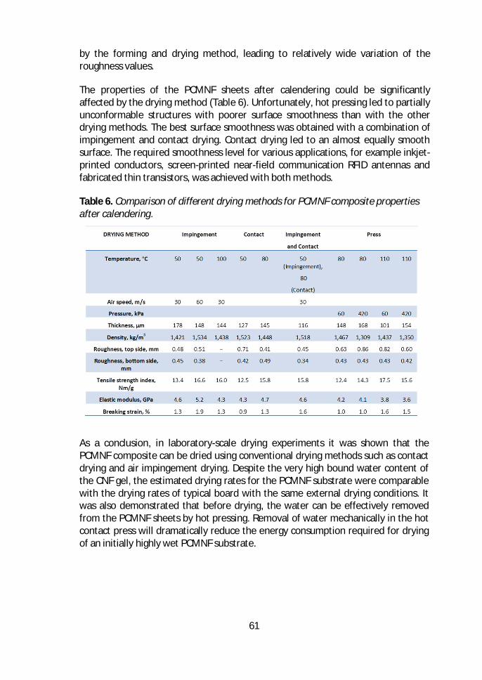
61
by the forming and drying method, leading to relatively wide variation of theroughness values.
The properties of the PCMNF sheets after calendering could be significantlyaffected by the drying method (Table 6). Unfortunately, hot pressing led to partiallyunconformable structures with poorer surface smoothness than with the otherdrying methods. The best surface smoothness was obtained with a combination ofimpingement and contact drying. Contact drying led to an almost equally smoothsurface. The required smoothness level for various applications, for example inkjet-printed conductors, screen-printed near-field communication RFID antennas andfabricated thin transistors, was achieved with both methods.
Table 6. Comparison of different drying methods for PCMNF composite propertiesafter calendering.
As a conclusion, in laboratory-scale drying experiments it was shown that thePCMNF composite can be dried using conventional drying methods such as contactdrying and air impingement drying. Despite the very high bound water content ofthe CNF gel, the estimated drying rates for the PCMNF substrate were comparablewith the drying rates of typical board with the same external drying conditions. Itwas also demonstrated that before drying, the water can be effectively removedfrom the PCMNF sheets by hot pressing. Removal of water mechanically in the hotcontact press will dramatically reduce the energy consumption required for dryingof an initially highly wet PCMNF substrate.
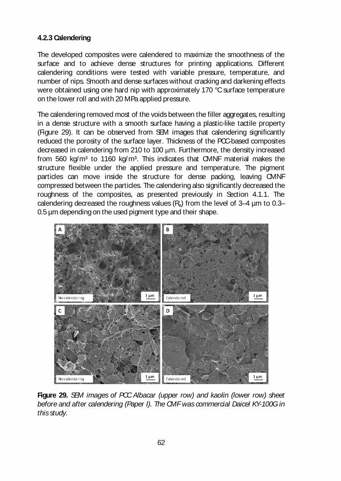
62
4.2.3 Calendering
The developed composites were calendered to maximize the smoothness of thesurface and to achieve dense structures for printing applications. Differentcalendering conditions were tested with variable pressure, temperature, andnumber of nips. Smooth and dense surfaces without cracking and darkening effectswere obtained using one hard nip with approximately 170 °C surface temperatureon the lower roll and with 20 MPa applied pressure.
The calendering removed most of the voids between the filler aggregates, resultingin a dense structure with a smooth surface having a plastic-like tactile property(Figure 29). It can be observed from SEM images that calendering significantlyreduced the porosity of the surface layer. Thickness of the PCC-based compositesdecreased in calendering from 210 to 100 μm. Furthermore, the density increasedfrom 560 kg/m³ to 1160 kg/m³. This indicates that CMNF material makes thestructure flexible under the applied pressure and temperature. The pigmentparticles can move inside the structure for dense packing, leaving CMNFcompressed between the particles. The calendering also significantly decreased theroughness of the composites, as presented previously in Section 4.1.1. Thecalendering decreased the roughness values (Ra) from the level of 3–4 µm to 0.3–0.5 µm depending on the used pigment type and their shape.
Figure 29. SEM images of PCC Albacar (upper row) and kaolin (lower row) sheetbefore and after calendering (Paper I). The CMF was commercial Daicel KY-100G inthis study.
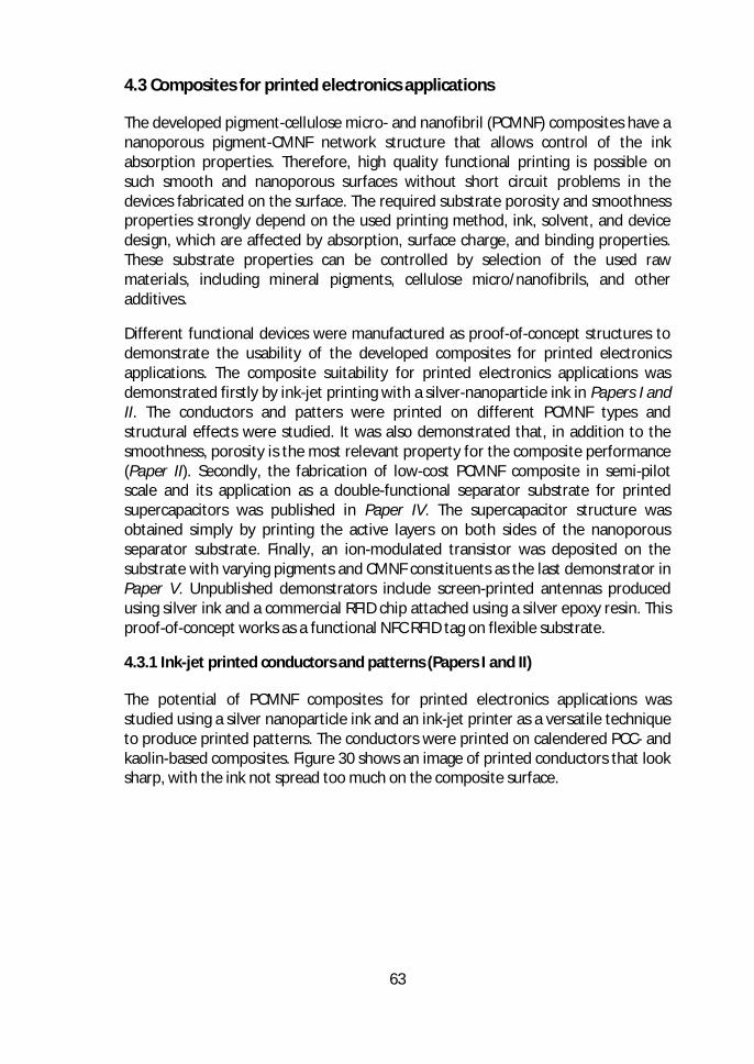
63
4.3 Composites for printed electronics applications
The developed pigment-cellulose micro- and nanofibril (PCMNF) composites have ananoporous pigment-CMNF network structure that allows control of the inkabsorption properties. Therefore, high quality functional printing is possible onsuch smooth and nanoporous surfaces without short circuit problems in thedevices fabricated on the surface. The required substrate porosity and smoothnessproperties strongly depend on the used printing method, ink, solvent, and devicedesign, which are affected by absorption, surface charge, and binding properties.These substrate properties can be controlled by selection of the used rawmaterials, including mineral pigments, cellulose micro/nanofibrils, and otheradditives.
Different functional devices were manufactured as proof-of-concept structures todemonstrate the usability of the developed composites for printed electronicsapplications. The composite suitability for printed electronics applications wasdemonstrated firstly by ink-jet printing with a silver-nanoparticle ink in Papers I andII. The conductors and patters were printed on different PCMNF types andstructural effects were studied. It was also demonstrated that, in addition to thesmoothness, porosity is the most relevant property for the composite performance(Paper II). Secondly, the fabrication of low-cost PCMNF composite in semi-pilotscale and its application as a double-functional separator substrate for printedsupercapacitors was published in Paper IV. The supercapacitor structure wasobtained simply by printing the active layers on both sides of the nanoporousseparator substrate. Finally, an ion-modulated transistor was deposited on thesubstrate with varying pigments and CMNF constituents as the last demonstrator inPaper V. Unpublished demonstrators include screen-printed antennas producedusing silver ink and a commercial RFID chip attached using a silver epoxy resin. Thisproof-of-concept works as a functional NFC RFID tag on flexible substrate.
4.3.1 Ink-jet printed conductors and patterns (Papers I and II)
The potential of PCMNF composites for printed electronics applications wasstudied using a silver nanoparticle ink and an ink-jet printer as a versatile techniqueto produce printed patterns. The conductors were printed on calendered PCC- andkaolin-based composites. Figure 30 shows an image of printed conductors that looksharp, with the ink not spread too much on the composite surface.
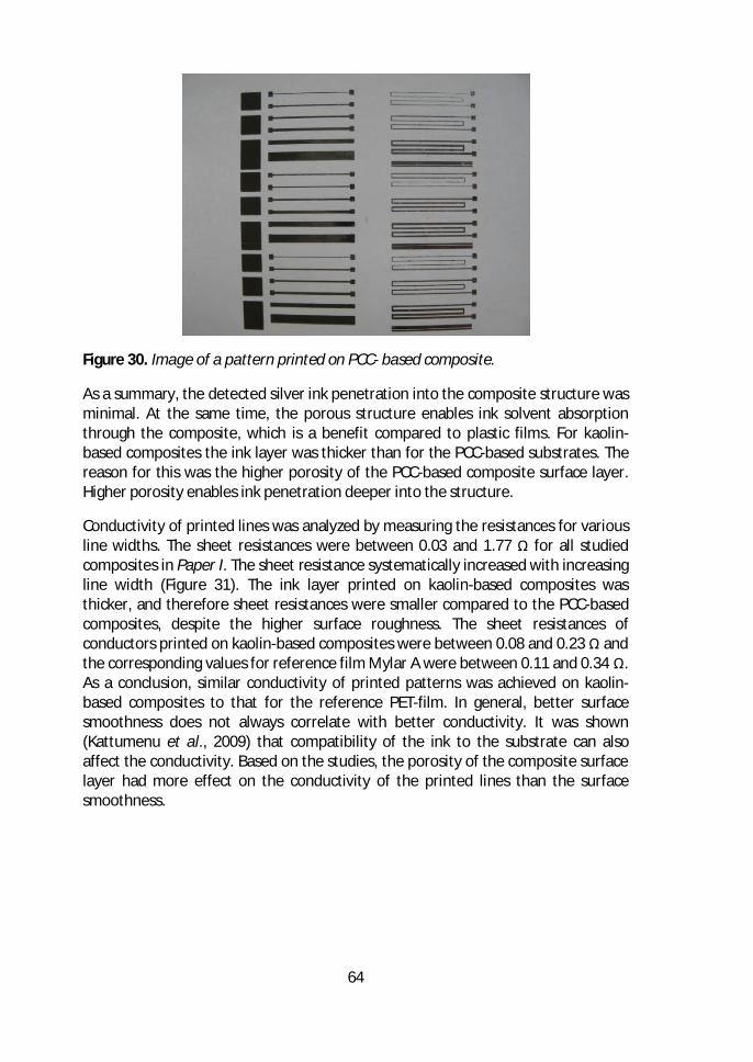
64
Figure 30. Image of a pattern printed on PCC- based composite.
As a summary, the detected silver ink penetration into the composite structure wasminimal. At the same time, the porous structure enables ink solvent absorptionthrough the composite, which is a benefit compared to plastic films. For kaolin-based composites the ink layer was thicker than for the PCC-based substrates. Thereason for this was the higher porosity of the PCC-based composite surface layer.Higher porosity enables ink penetration deeper into the structure.
Conductivity of printed lines was analyzed by measuring the resistances for variousline widths. The sheet resistances were between 0.03 and 1.77 Ω for all studiedcomposites in Paper I. The sheet resistance systematically increased with increasingline width (Figure 31). The ink layer printed on kaolin-based composites wasthicker, and therefore sheet resistances were smaller compared to the PCC-basedcomposites, despite the higher surface roughness. The sheet resistances ofconductors printed on kaolin-based composites were between 0.08 and 0.23 Ω andthe corresponding values for reference film Mylar A were between 0.11 and 0.34 Ω.As a conclusion, similar conductivity of printed patterns was achieved on kaolin-based composites to that for the reference PET-film. In general, better surfacesmoothness does not always correlate with better conductivity. It was shown(Kattumenu et al., 2009) that compatibility of the ink to the substrate can alsoaffect the conductivity. Based on the studies, the porosity of the composite surfacelayer had more effect on the conductivity of the printed lines than the surfacesmoothness.
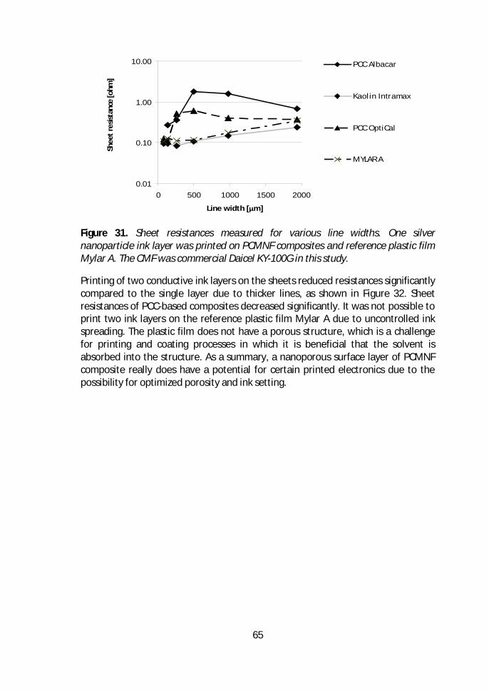
65
Figure 31. Sheet resistances measured for various line widths. One silvernanoparticle ink layer was printed on PCMNF composites and reference plastic filmMylar A. The CMF was commercial Daicel KY-100G in this study.
Printing of two conductive ink layers on the sheets reduced resistances significantlycompared to the single layer due to thicker lines, as shown in Figure 32. Sheetresistances of PCC-based composites decreased significantly. It was not possible toprint two ink layers on the reference plastic film Mylar A due to uncontrolled inkspreading. The plastic film does not have a porous structure, which is a challengefor printing and coating processes in which it is beneficial that the solvent isabsorbed into the structure. As a summary, a nanoporous surface layer of PCMNFcomposite really does have a potential for certain printed electronics due to thepossibility for optimized porosity and ink setting.
0.01
0.10
1.00
10.00
0 500 1000 1500 2000
Line width [μm]
Shee
tres
istan
ce[o
hm]
PCC Albacar
Kaol in Intramax
PCC OptiCal
MYLAR A
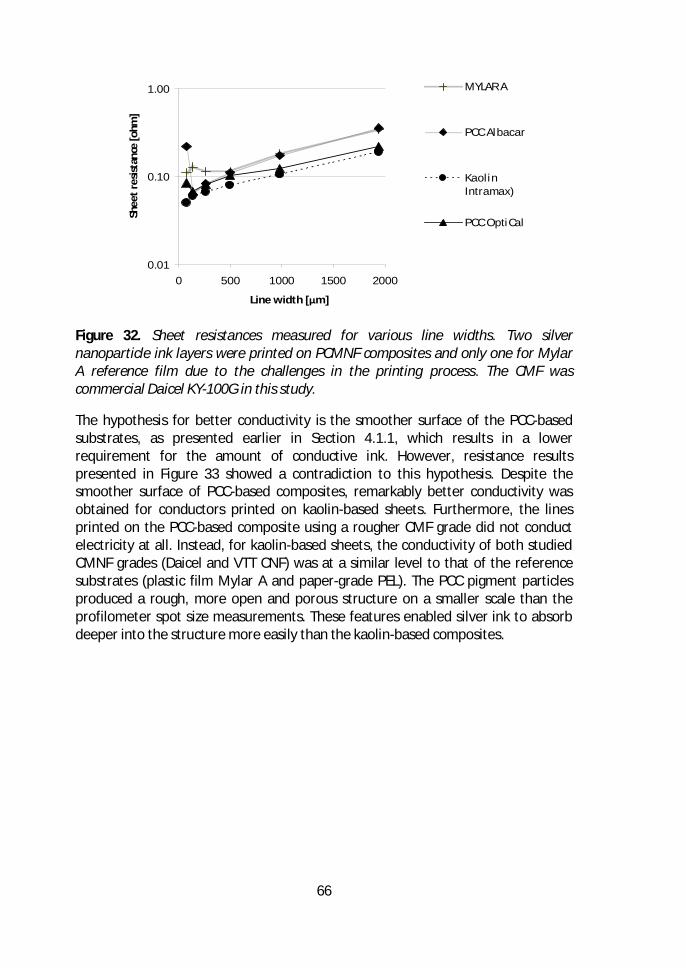
66
Figure 32. Sheet resistances measured for various line widths. Two silvernanoparticle ink layers were printed on PCMNF composites and only one for MylarA reference film due to the challenges in the printing process. The CMF wascommercial Daicel KY-100G in this study.
The hypothesis for better conductivity is the smoother surface of the PCC-basedsubstrates, as presented earlier in Section 4.1.1, which results in a lowerrequirement for the amount of conductive ink. However, resistance resultspresented in Figure 33 showed a contradiction to this hypothesis. Despite thesmoother surface of PCC-based composites, remarkably better conductivity wasobtained for conductors printed on kaolin-based sheets. Furthermore, the linesprinted on the PCC-based composite using a rougher CMF grade did not conductelectricity at all. Instead, for kaolin-based sheets, the conductivity of both studiedCMNF grades (Daicel and VTT CNF) was at a similar level to that of the referencesubstrates (plastic film Mylar A and paper-grade PEL). The PCC pigment particlesproduced a rough, more open and porous structure on a smaller scale than theprofilometer spot size measurements. These features enabled silver ink to absorbdeeper into the structure more easily than the kaolin-based composites.
0.01
0.10
1.00
0 500 1000 1500 2000
Line width [μm]
Shee
tres
istan
ce[o
hm]
MYLAR A
PCC Albacar
KaolinIntramax)
PCC OptiCal
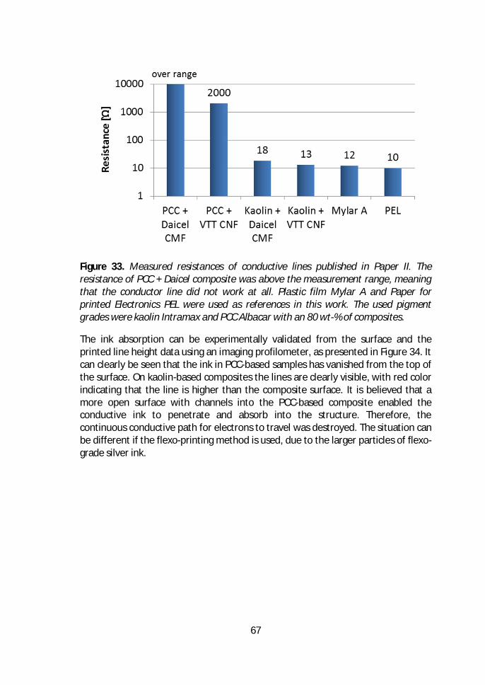
67
Figure 33. Measured resistances of conductive lines published in Paper II. Theresistance of PCC + Daicel composite was above the measurement range, meaningthat the conductor line did not work at all. Plastic film Mylar A and Paper forprinted Electronics PEL were used as references in this work. The used pigmentgrades were kaolin Intramax and PCC Albacar with an 80 wt-% of composites.
The ink absorption can be experimentally validated from the surface and theprinted line height data using an imaging profilometer, as presented in Figure 34. Itcan clearly be seen that the ink in PCC-based samples has vanished from the top ofthe surface. On kaolin-based composites the lines are clearly visible, with red colorindicating that the line is higher than the composite surface. It is believed that amore open surface with channels into the PCC-based composite enabled theconductive ink to penetrate and absorb into the structure. Therefore, thecontinuous conductive path for electrons to travel was destroyed. The situation canbe different if the flexo-printing method is used, due to the larger particles of flexo-grade silver ink.
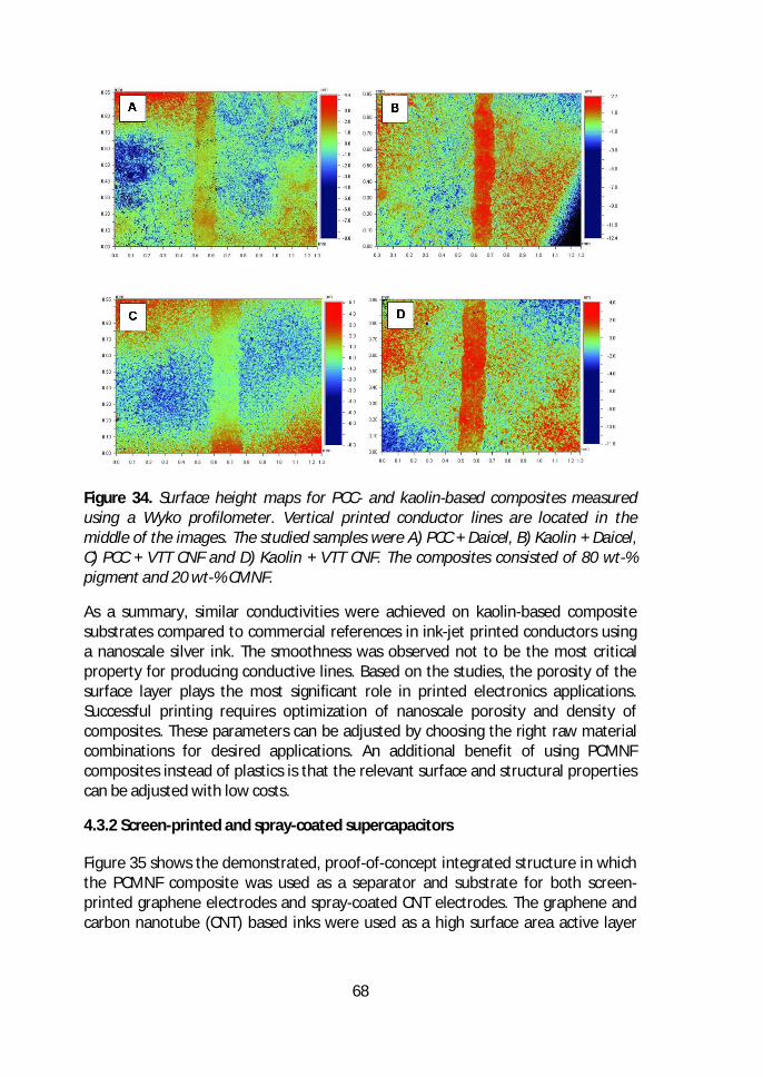
68
Figure 34. Surface height maps for PCC- and kaolin-based composites measuredusing a Wyko profilometer. Vertical printed conductor lines are located in themiddle of the images. The studied samples were A) PCC + Daicel, B) Kaolin + Daicel,C) PCC + VTT CNF and D) Kaolin + VTT CNF. The composites consisted of 80 wt-%pigment and 20 wt-% CMNF.
As a summary, similar conductivities were achieved on kaolin-based compositesubstrates compared to commercial references in ink-jet printed conductors usinga nanoscale silver ink. The smoothness was observed not to be the most criticalproperty for producing conductive lines. Based on the studies, the porosity of thesurface layer plays the most significant role in printed electronics applications.Successful printing requires optimization of nanoscale porosity and density ofcomposites. These parameters can be adjusted by choosing the right raw materialcombinations for desired applications. An additional benefit of using PCMNFcomposites instead of plastics is that the relevant surface and structural propertiescan be adjusted with low costs.
4.3.2 Screen-printed and spray-coated supercapacitors
Figure 35 shows the demonstrated, proof-of-concept integrated structure in whichthe PCMNF composite was used as a separator and substrate for both screen-printed graphene electrodes and spray-coated CNT electrodes. The graphene andcarbon nanotube (CNT) based inks were used as a high surface area active layer
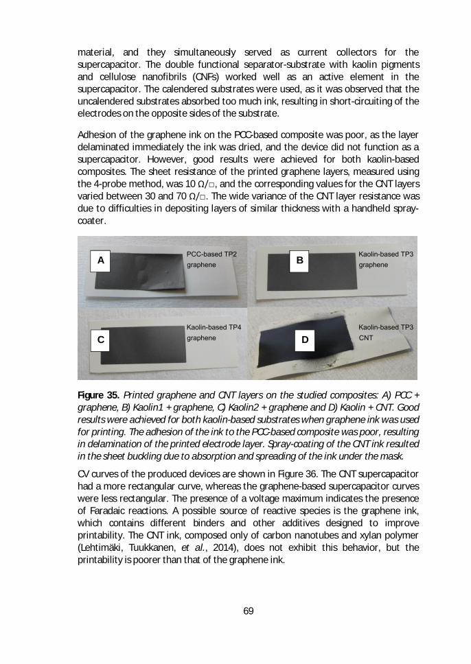
69
material, and they simultaneously served as current collectors for thesupercapacitor. The double functional separator-substrate with kaolin pigmentsand cellulose nanofibrils (CNFs) worked well as an active element in thesupercapacitor. The calendered substrates were used, as it was observed that theuncalendered substrates absorbed too much ink, resulting in short-circuiting of theelectrodes on the opposite sides of the substrate.
Adhesion of the graphene ink on the PCC-based composite was poor, as the layerdelaminated immediately the ink was dried, and the device did not function as asupercapacitor. However, good results were achieved for both kaolin-basedcomposites. The sheet resistance of the printed graphene layers, measured usingthe 4-probe method, was 10 Ω/, and the corresponding values for the CNT layersvaried between 30 and 70 Ω/. The wide variance of the CNT layer resistance wasdue to difficulties in depositing layers of similar thickness with a handheld spray-coater.
Figure 35. Printed graphene and CNT layers on the studied composites: A) PCC +graphene, B) Kaolin1 + graphene, C) Kaolin2 + graphene and D) Kaolin + CNT. Goodresults were achieved for both kaolin-based substrates when graphene ink was usedfor printing. The adhesion of the ink to the PCC-based composite was poor, resultingin delamination of the printed electrode layer. Spray-coating of the CNT ink resultedin the sheet buckling due to absorption and spreading of the ink under the mask.
CV curves of the produced devices are shown in Figure 36. The CNT supercapacitorhad a more rectangular curve, whereas the graphene-based supercapacitor curveswere less rectangular. The presence of a voltage maximum indicates the presenceof Faradaic reactions. A possible source of reactive species is the graphene ink,which contains different binders and other additives designed to improveprintability. The CNT ink, composed only of carbon nanotubes and xylan polymer(Lehtimäki, Tuukkanen, et al., 2014), does not exhibit this behavior, but theprintability is poorer than that of the graphene ink.
A B
C D
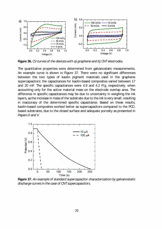
70
Figure 36. CV curves of the devices with a) graphene and b) CNT electrodes.
The quantitative properties were determined from galvanostatic measurements.An example curve is shown in Figure 37. There were no significant differencesbetween the two types of kaolin pigment materials used in the graphenesupercapacitors: the capacitances for kaolin-based composites varied between 17and 20 mF. The specific capacitances were 4.9 and 4.2 F/g, respectively, whenaccounting only for the active material mass on the electrode overlap area. Thedifference in specific capacitances may be due to uncertainty in weighing the inklayers, as the increase in mass of the substrate due to the ink is very small, resultingin inaccuracy of the determined specific capacitance. Based on these results,kaolin-based composites worked better as supercapacitors compared to the PCC-based substrates, due to the closed surface and adequate porosity as presented inPapers II and V.
Figure 37. An example of standard supercapacitor characterization by galvanostaticdischarge curves in the case of CNT supercapacitors.
a) b)
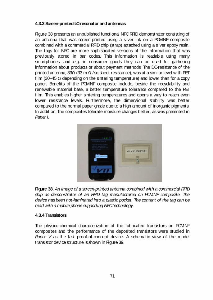
71
4.3.3 Screen-printed LC-resonator and antennas
Figure 38 presents an unpublished functional NFC RFID demonstrator consisting ofan antenna that was screen-printed using a silver ink on a PCMNF compositecombined with a commercial RFID chip (strap) attached using a silver epoxy resin.The tags for NFC are more sophisticated versions of the information that waspreviously stored in bar codes. This information is readable using manysmartphones, and e.g. in consumer goods they can be used for gatheringinformation about products or about payment methods. The DC-resistance of theprinted antenna, 33Ω (33 m Ω /sq sheet resistance), was at a similar level with PETfilm (30–45 Ω depending on the sintering temperature) and lower than for a copypaper. Benefits of the PCMNF composite include, beside the recyclability andrenewable material base, a better temperature tolerance compared to the PETfilm. This enables higher sintering temperatures and opens a way to reach evenlower resistance levels. Furthermore, the dimensional stability was bettercompared to the normal paper grade due to a high amount of inorganic pigments.In addition, the composites tolerate moisture changes better, as was presented inPaper I.
Figure 38. An image of a screen-printed antenna combined with a commercial RFIDship as demonstrator of an RFID tag manufactured on PCMNF composite. Thedevice has been hot-laminated into a plastic pocket. The content of the tag can beread with a mobile phone supporting NFC technology.
4.3.4 Transistors
The physico-chemical characterization of the fabricated transistors on PCMNFcomposites and the performance of the deposited transistors were studied inPaper V as the last proof-of-concept device. A schematic view of the modeltransistor device structure is shown in Figure 39.
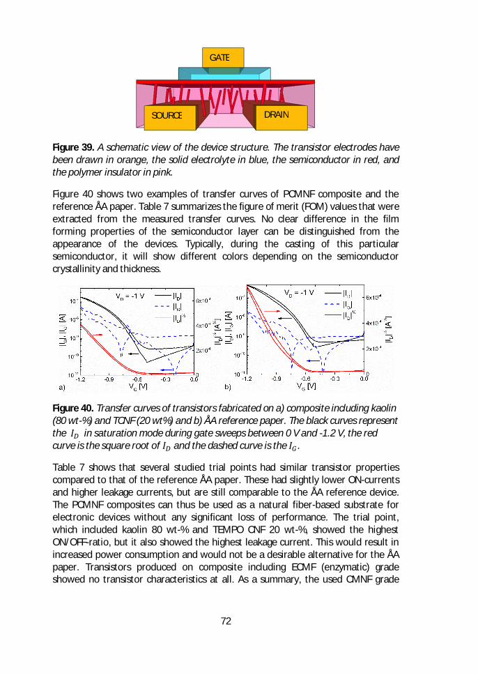
72
Figure 39. A schematic view of the device structure. The transistor electrodes havebeen drawn in orange, the solid electrolyte in blue, the semiconductor in red, andthe polymer insulator in pink.
Figure 40 shows two examples of transfer curves of PCMNF composite and thereference ÅA paper. Table 7 summarizes the figure of merit (FOM) values that wereextracted from the measured transfer curves. No clear difference in the filmforming properties of the semiconductor layer can be distinguished from theappearance of the devices. Typically, during the casting of this particularsemiconductor, it will show different colors depending on the semiconductorcrystallinity and thickness.
Figure 40. Transfer curves of transistors fabricated on a) composite including kaolin(80 wt-%) and TCNF (20 wt%) and b) ÅA reference paper. The black curves representthe in saturation mode during gate sweeps between 0 V and -1.2 V, the redcurve is the square root of and the dashed curve is the .
Table 7 shows that several studied trial points had similar transistor propertiescompared to that of the reference ÅA paper. These had slightly lower ON-currentsand higher leakage currents, but are still comparable to the ÅA reference device.The PCMNF composites can thus be used as a natural fiber-based substrate forelectronic devices without any significant loss of performance. The trial point,which included kaolin 80 wt-% and TEMPO CNF 20 wt-%, showed the highestON/OFF-ratio, but it also showed the highest leakage current. This would result inincreased power consumption and would not be a desirable alternative for the ÅApaper. Transistors produced on composite including ECMF (enzymatic) gradeshowed no transistor characteristics at all. As a summary, the used CMNF grade
SOURCE DRAIN
GATE
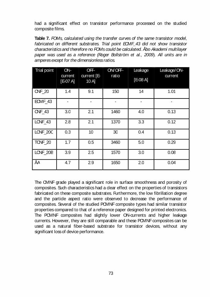
73
had a significant effect on transistor performance processed on the studiedcomposite films.
Table 7. FOMs, calculated using the transfer curves of the same transistor model,fabricated on different substrates. Trial point ECMF_43 did not show transistorcharacteristics and therefore no FOMs could be calculated. Åbo Akademi multilayerpaper was used as a reference (Roger Bollström et al., 2009). All units are inamperes except for the dimensionless ratios.
Trial point ON-current[E-07 A]
OFF-current [E-
10 A]
ON/OFF-ratio
Leakage
[E-08 A]
Leakage/ON-current
CNF_20 1.4 9.1 150 14 1.01
ECMF_43 - - - - -
CNF_43 3.0 2.1 1460 4.0 0.13
LCNF_43 2.8 2.1 1370 3.3 0.12
LCNF_20C 0.3 10 30 0.4 0.13
TCNF_20 1.7 0.5 3460 5.0 0.29
LCNF_20B 3.9 2.5 1570 3.0 0.08
ÅA 4.7 2.9 1650 2.0 0.04
The CMNF grade played a significant role in surface smoothness and porosity ofcomposites. Such characteristics had a clear effect on the properties of transistorsfabricated on these composite substrates. Furthermore, the low fibrillation degreeand the particle aspect ratio were observed to decrease the performance ofcomposites. Several of the studied PCMNF composite types had similar transistorproperties compared to that of a reference paper designed for printed electronics.The PCMNF composites had slightly lower ON-currents and higher leakagecurrents. However, they are still comparable and these PCMNF composites can beused as a natural fiber-based substrate for transistor devices, without anysignificant loss of device performance.
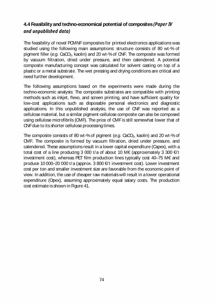
74
4.4 Feasibility and techno-economical potential of composites (Paper IVand unpublished data)
The feasibility of novel PCMNF composites for printed electronics applications wasstudied using the following main assumptions: structure consists of 80 wt-% ofpigment filler (e.g. CaCO3, kaolin) and 20 wt-% of CNF. The composite was formedby vacuum filtration, dried under pressure, and then calendered. A potentialcomposite manufacturing concept was calculated for solvent casting on top of aplastic or a metal substrate. The wet pressing and drying conditions are critical andneed further development.
The following assumptions based on the experiments were made during thetechno-economic analysis: The composite substrates are compatible with printingmethods such as inkjet, flexo, and screen printing, and have sufficient quality forlow-cost applications such as disposable personal electronics and diagnosticapplications. In this unpublished analysis, the use of CNF was reported as acellulose material, but a similar pigment-cellulose composite can also be composedusing cellulose microfibrils (CMF). The price of CMF is still somewhat lower that ofCNF due to its shorter cellulose processing times.
The composite consists of 80 wt-% of pigment (e.g. CaCO3, kaolin) and 20 wt-% ofCMF. The composite is formed by vacuum filtration, dried under pressure, andcalendered. These assumptions result in a lower capital expenditure (Capex), with atotal cost of a line producing 3 000 t/a of about 10 M€ (approximately 3 300 €/tinvestment cost), whereas PET film production lines typically cost 40–75 M€ andproduce 10 000–20 000 t/a (approx. 3 800 €/t investment cost). Lower investmentcost per ton and smaller investment size are favorable from the economic point ofview. In addition, the use of cheaper raw materials will result in a lower operationalexpenditure (Opex), assuming approximately equal salary costs. The productioncost estimate is shown in Figure 41.
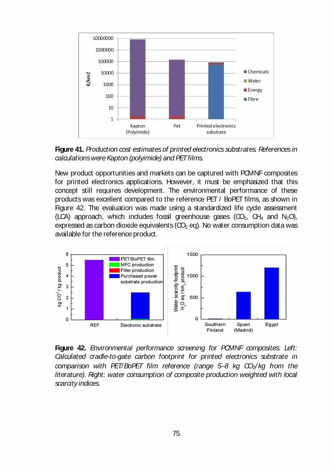
75
Figure 41. Production cost estimates of printed electronics substrates. References incalculations were Kapton (polyimide) and PET films.
New product opportunities and markets can be captured with PCMNF compositesfor printed electronics applications. However, it must be emphasized that thisconcept still requires development. The environmental performance of theseproducts was excellent compared to the reference PET / BoPET films, as shown inFigure 42. The evaluation was made using a standardized life cycle assessment(LCA) approach, which includes fossil greenhouse gases (CO2, CH4 and N2O),expressed as carbon dioxide equivalents (CO2 eq). No water consumption data wasavailable for the reference product.
Figure 42. Environmental performance screening for PCMNF composites: Left:Calculated cradle-to-gate carbon footprint for printed electronics substrate incomparison with PET/BoPET film reference (range 5–8 kg CO2/kg from theliterature). Right: water consumption of composite production weighted with localscarcity indices.
76
5 Conclusions
The PCMNF composites manufactured and studied in this thesis work differ fromtraditional paper and board materials due to the high amount of inorganic pigment(up to 90%) and the characteristics of cellulose nanofibrils (CNF). PCMNFcomposites are sustainable, flexible, and can tolerate high sintering temperaturesfor printed electronics applications to replace plastic materials. An additionalbenefit of PCMNF composites is that the relevant surface and structural propertiescan be adjusted at low cost. The composite films can be manufactured by a filmcasting method in a semi-pilot scale. Moreover, the results of this work show that itwill be possible to up-scale the production method to industrial scale in future.
The developed composites need to fulfill certain quality requirements for printedelectronics applications. The used manufacturing process significantly influencesthese properties. The porosity of the structure was found to be a more relevantproperty than surface smoothness in printed electronics applications forproduction of conductive lines. This means that a successful printing of functionaldevices needs to be optimized with the nanoscale porosity of the composites. Themain effort of this work was to understand the interactions between compositeraw materials and manufacturing process phases and the obtained properties ofcomposites. Moreover, these properties of composites had a great influence on thecharacteristics of manufactured proof-of-concept functional devices. Hence, thetargeted end-use application determines the necessary substrate properties.
Based on this work, the porosity of surface layer plays the most significant role inprinted electronics applications. The surface pore volume can be optimized for theused printing method and ink by the choice of pigment type, amount, and CMNFmaterial grade. These parameters can be adjusted by using the right raw materialcombinations for the desired applications. Based on these results, kaolin-basedcomposites work better as a substrate compared to PCC-based composites due totheir more suitable porosity. The CMNF grade also played a significant role insurface smoothness and porosity of composites. These characteristics had a cleareffect on the functional devices fabricated on the composite substrates.Furthermore, low fibrillation degree and particle aspect ratio were observed toreduce the performance of composites.
Drying experiments in laboratory scale showed that the PCMNF composite can bedried by using conventional drying methods such as contact drying and airimpingement drying. Despite the very high bound water content of the CNF gel, theestimated drying rates for the PCMNF substrate were comparable with the dryingrates of a typical paperboard with the same external drying conditions. It was alsodemonstrated that before drying, the water can be effectively removed from thePCMNF sheets by hot pressing. The removal of water mechanically in the hot
77
contact press dramatically reduces the energy consumption required for drying ofan initially highly wet PCMNF substrate.
In order to increase the number of sustainable and economically feasible productsin the printed electronics markets, the production costs need to be taken intoaccount. In this work, it was shown that using CMNF together with inorganicpigments to produce cost-effective, feasible, and novel films can have advantages.However, more work is needed to obtain smooth and surface nano-porouscomposite films suitable for the wet pressing method. A roll-to-roll productionprocess for inexpensive energy storage devices, e.g. supercapacitors, is possibleusing such a composite as a separator-substrate. The porous electrode layers madewith environmentally friendly aqueous dispersions of carbon nanotubes (CNT) orgraphene can be used. The electrodes can be coated or printed in pilot scale onboth sides of the separator substrate. This will be a considerable advantagecompared to the current production methods of supercapacitors.
78
6 Suggestions for further work
The industrial production of functional devices using paper or novel composites isstill currently rather limited. The volume needs for these specialty papers are notcomparable to those of traditional paper grade production, due to the currentlylow market demand. As a future scenario, smaller and more specialised machineryis needed with flexible and movable production units. This will allow the productionof different end-use application devices with the same machinery.
Foam coating (Kenttä et al., 2014, Kinnunen-Raudaskoski et al., 2014) and foamforming (Lehmonen et al., 2013) are currently attracting a growing interest inpaperboard industry. The use of foam allows an addition of a wide variety ofalternative raw materials, such as nanoparticles, CMNF and long flexible fibers intothe paperboard webs. These technologies will also lead to more versatileproduction methods that are required for manufacturing totally new high-valueadded end products. Naturally, energy efficient technologies are also of greatinterest and with foam-based technologies in paper making, water consumptioncan be reduced and less energy is needed in drying.
A possible future study could be to use a wet laid process for the next generationcost-effective mass production of separator substrate in real industrial conditions.A good candidate here is the impregnation of the PCMNF with a foam coatingtechnique on a fiber web made from conventional cellulose pulp in a wet laidprocess before the forming section. The advantage of such an approach would bean increase in the strength of the PCMNF separator substrate, and a dramaticincrease in production capacity due to a higher production speed and a wider web.
79
ReferencesAbdulKhalil,H.P.S.,Bhat,A.H.,&IreanaYusra,A.F.(2012).Greencompositesfrom
sustainablecellulosenanofibrils:Areview.CarbohydratePolymers.https://doi.org/10.1016/j.carbpol.2011.08.078
Aitomäki,Y.,&Oksman,K.(2014).Reinforcingefficiencyofnanocelluloseinpolymers.ReactiveandFunctionalPolymers,85,151–156.https://doi.org/10.1016/j.reactfunctpolym.2014.08.010
Allen,M.L.,Aronniemi,M.,Mattila,T.,Alastalo,A.,Ojanperä,K.,Suhonen,M.,&Seppä,H.(2008).Electricalsinteringofnanoparticlestructures.Nanotechnology,19(17),175201.https://doi.org/10.1088/0957-4484/19/17/175201
An,K.H.,Kim,W.S.,Park,Y.S.,Choi,Y.C.,Lee,S.M.,Chung,D.C.,…Lee,Y.H.(2001).Supercapacitorsusingsingle-walledcarbonnanotubeelectrodes.AdvancedMaterials,13(7),497–500.https://doi.org/10.1002/1521-4095(200104)13:7<497::AID-ADMA497>3.0.CO;2-H
Andersson.(2012).Contactingpaper-basedsupercapacitorstoprintedelectronicsonpapersubstrates.NordicPulpandPaperResearchJournal,27(2),476–480.https://doi.org/10.3183/NPPRJ-2012-27-02-p476-480
Asensio,M.C.,Seyed-Yagoobi,J.,Lehtinen,J.A.,Karlsson,M.A.,Timofeev,O.N.,&Juppi,K.(2007).ComparisonofSeveralMulti-CylinderPaperDryingSimulationModels.DryingTechnology,(787743727).https://doi.org/10.1080/07373939508916992
Aulin,C.,Salazar-Alvarez,G.,&Lindström,T.(2012).Highstrength,flexibleandtransparentnanofibrillatedcellulose-nanoclaybiohybridfilmswithtunableoxygenandwatervaporpermeability.Nanoscale,4(20),6622–8.https://doi.org/10.1039/c2nr31726e
Azarova,N.A.,Owen,J.W.,McLellan,C.A.,Grimminger,M.A.,Chapman,E.K.,Anthony,J.E.,&Jurchescu,O.D.(2010).Fabricationoforganicthin-filmtransistorsbyspray-depositionforlow-cost,large-areaelectronics.OrganicElectronics:Physics,Materials,Applications,11(12),1960–1965.https://doi.org/10.1016/j.orgel.2010.09.008
Azeredo,H.M.C.,Mattoso,L.H.C.,Avena-Bustillos,R.J.,Filho,G.C.,Munford,M.L.,Wood,D.,&McHugh,T.H.(2010).Nanocellulosereinforcedchitosancompositefilmsasaffectedbynanofillerloadingandplasticizercontent.JournalofFoodScience,75(1),1–7.https://doi.org/10.1111/j.1750-3841.2009.01386.x
Bai,Y.(2016).SamuelGreengard,TheInternetofThings,10,5604–5607.Berggren,M.,Nilsson,D.,&Robinson,N.D.(2007).Organicmaterialsforprinted
electronics.NatureMaterials,6(1),3–5.https://doi.org/10.1038/nmat1817Berglund,L.(2005).Cellulose-basednanocomposites.NaturalFibers,Biopolymers,and
Biocomposites,807–832.https://doi.org/10.1201/9780203508206.ch1Bollström,R.,Määttänen,A.,Tobjörk,D.,Ihalainen,P.,Kaihovirta,N.,Österbacka,R.,…
Toivakka,M.(2009).Amultilayercoatedfiber-basedsubstratesuitableforprintedfunctionality.OrganicElectronics:Physics,Materials,Applications,10(5),1020–1023.https://doi.org/10.1016/j.orgel.2009.04.014
Bollström,R.,Tobjörk,D.,&Dolietis,P.(2012).Roll-to-rollprintedelectronicsonpaper.
80
Roll-to-RollPrintedElectronicsonPaper.Retrievedfromhttp://scholar.google.com/scholar?q=Roll-to-rollprintedelectronicsonpaper&btnG=&hl=en&num=20&as_sdt=0%2C22VN-readcube.com
Boluk,Y.,Lahiji,R.,Zhao,L.,&McDermott,M.T.(2011).Suspensionviscositiesandshapeparameterofcellulosenanocrystals(CNC).ColloidsandSurfacesA:PhysicochemicalandEngineeringAspects,377(1–3),297–303.https://doi.org/10.1016/j.colsurfa.2011.01.003
Bras,J.,Viet,D.,Bruzzese,C.,&Dufresne,A.(2011).Correlationbetweenstiffnessofsheetspreparedfromcellulosewhiskersandnanoparticlesdimensions.CarbohydratePolymers,84(1),211–215.https://doi.org/10.1016/j.carbpol.2010.11.022
Brodin,F.W.,Gregersen,Ø.W.,&Syverud,K.(2014).Cellulosenanofibrils:Challengesandpossibilitiesasapaperadditiveorcoatingmaterial-Areview.NordicPulpandPaperResearchJournal,29(1),156–166.https://doi.org/10.3183/NPPRJ-2014-29-01-p156-166
Bundy,W.M.,&Ishley,J.N.(1991).Kaolininpaperfillingandcoating.AppliedClayScience,5(5–6),397–420.https://doi.org/10.1016/0169-1317(91)90015-2
Chan,Y.J.,Kung,C.P.,&Pei,Z.(2005).PrintedRFID:technologyandapplication.In2005IEEEInternationalWkshponRadio-FrequencyIntegrationTechnology:IntegratedCircuitsforWidebandComm&WirelessSensorNetworks(pp.139–141).https://doi.org/10.1109/RFIT.2005.1598894
Chang,J.,Ge,T.,&Sanchez-Sinencio,E.(2012).Challengesofprintedelectronicsonflexiblesubstrates.InMidwestSymposiumonCircuitsandSystems(pp.582–585).https://doi.org/10.1109/MWSCAS.2012.6292087
Chen,T.,&Dai,L.(2013).Carbonnanomaterialsforhigh-performancesupercapacitors.MaterialsToday.https://doi.org/10.1016/j.mattod.2013.07.002
Chen,Z.,Augustyn,V.,Wen,J.,Zhang,Y.,Shen,M.,Dunn,B.,&Lu,Y.(2011).High-performancesupercapacitorsbasedonintertwinedCNT/V2O5nanowirenanocomposites.AdvancedMaterials,23(6),791–795.https://doi.org/10.1002/adma.201003658
Ching,Y.C.,Rahman,A.,Ching,K.Y.,Sukiman,N.L.,&Chuah,C.H.(2015).PreparationandCharacterizationofPolyvinylAlcohol-BasedCompositeReinforcedwithNanocelluloseand,10(2),3364–3377.
Chinga-Carrasco,G.,&Syverud,K.(2014).Pretreatment-dependentsurfacechemistryofwoodnanocelluloseforpH-sensitivehydrogels.JournalofBiomaterialsApplications,29(7491),423–432.https://doi.org/10.1177/0885328214531511
Choi,K.-H.,Yoo,J.,Lee,C.K.,&Lee,S.-Y.(2016).All-inkjet-printed,solid-stateflexiblesupercapacitorsonpaper.EnergyEnviron.Sci.,12,871–872.https://doi.org/10.1039/C6EE00966B
Costa,S.V.,Pingel,P.,Janietz,S.,&Nogueira,A.F.(2016).Invertedorganicsolarcellsusingnanocelluloseassubstrate.JournalofAppliedPolymerScience,133(28).https://doi.org/10.1002/app.43679
Das,R.,&Harrop,P.(2012).Printed,Organic\&FlexibleElectronicsForecasts,Players\&Opportunities2011-2021.SandlerResearchMarketResearchReportsDatabase.
DeOliveira,M.H.,Tejado,A.,&VanDeVen,T.G.M.(2009).Effectsoffillersonthewet
81
webstrengthofpaper.NordicPulpandPaperResearchJournal,24(2).Dimic-Misic,K.,Gane,P.A.C.,&Paltakari,J.(2013).Microandnanofibrillatedcellulose
asarheologymodifieradditiveinCMC-containingpigment-coatingformulations.IndustrialandEngineeringChemistryResearch,52(45),16066–16083.https://doi.org/10.1021/ie4028878
Dimic-Misic,K.,Puisto,A.,Paltakari,J.,Alava,M.,&Maloney,T.(2013).Theinfluenceofshearonthedewateringofhighconsistencynanofibrillatedcellulosefurnishes.Cellulose,20(4),1853–1864.https://doi.org/10.1007/s10570-013-9964-9
Dogome,K.,Enomae,T.,&Isogai,A.(2013).Methodforcontrollingsurfaceenergiesofpapersubstratestocreatepaper-basedprintedelectronics.ChemicalEngineeringandProcessing:ProcessIntensification,68,21–25.https://doi.org/10.1016/j.cep.2013.01.003
Eda,G.,&Chhowalla,M.(2009).Graphene-basedcompositethinfilmsforelectronics.NanoLetters,9(2),814–818.https://doi.org/10.1021/n18035367
Eom,S.H.,Senthilarasu,S.,Uthirakumar,P.,Yoon,S.C.,Lim,J.,Lee,C.,…Lee,S.H.(2009).Polymersolarcellsbasedoninkjet-printedPEDOT:PSSlayer.OrganicElectronics:Physics,Materials,Applications,10(3),536–542.https://doi.org/10.1016/j.orgel.2009.01.015
Fao.(2013).Foodwasteharmsclimate,water,landandbiodiversity–newFAOreport.FoodandAgricultureOrganizationofTheUnitedNations.Retrievedfromodwasteharmsclimate,water,landandbiodiversity ?newFAOreport
Fujisawa,S.,Okita,Y.,Fukuzumi,H.,Saito,T.,&Isogai,A.(2011).PreparationandcharacterizationofTEMPO-oxidizedcellulosenanofibrilfilmswithfreecarboxylgroups.CarbohydratePolymers,84(1),579–583.https://doi.org/10.1016/j.carbpol.2010.12.029
Fukuzumi,H.,Saito,T.,Iwata,T.,Kumamoto,Y.,&Isogai,A.(2009).TransparentandhighgasbarrierfilmsofcellulosenanofiberspreparedbyTEMPO-mediatedoxidation.Biomacromolecules,10(1),162–165.https://doi.org/10.1021/bm801065u
Galagan,Y.,Coenen,E.W.C.,Abbel,R.,VanLammeren,T.J.,Sabik,S.,Barink,M.,…Blom,P.W.M.(2013).Photonicsinteringofinkjetprintedcurrentcollectinggridsfororganicsolarcellapplications.OrganicElectronics:Physics,Materials,Applications,14(1),38–46.https://doi.org/10.1016/j.orgel.2012.10.012
Gaspar,C.,Passoja,S.,Olkkonen,J.,&Smolander,M.(2016).IR-sinteringefficiencyoninkjet-printedconductivestructuresonpapersubstrates.MicroelectronicEngineering,149,135–140.https://doi.org/10.1016/j.mee.2015.10.006
Georgi-Maschler,T.,Friedrich,B.,Weyhe,R.,Heegn,H.,&Rutz,M.(2012).DevelopmentofarecyclingprocessforLi-ionbatteries.JournalofPowerSources,207,173–182.https://doi.org/10.1016/j.jpowsour.2012.01.152
González,I.,Alcalà,M.,Chinga-Carrasco,G.,Vilaseca,F.,Boufi,S.,&Mutjé,P.(2014).Frompapertonanopaper:Evolutionofmechanicalandphysicalproperties.Cellulose,21(4),2599–2609.https://doi.org/10.1007/s10570-014-0341-0
Grau,G.,Kitsomboonloha,R.,Swisher,S.L.,Kang,H.,&Subramanian,V.(2014).Printedtransistorsonpaper:Towardssmartconsumerproductpackaging.AdvancedFunctionalMaterials,24(32),5067–5074.https://doi.org/10.1002/adfm.201400129
82
Graupner,N.,Herrmann,A.S.,&Müssig,J.(2009).Naturalandman-madecellulosefibre-reinforcedpoly(lacticacid)(PLA)composites:Anoverviewaboutmechanicalcharacteristicsandapplicationareas.CompositesPartA:AppliedScienceandManufacturing,40(6–7),810–821.https://doi.org/10.1016/j.compositesa.2009.04.003
Guillén,C.,&Herrero,J.(2005).ComparisonstudyofITOthinfilmsdepositedbysputteringatroomtemperatureontopolymerandglasssubstrates.InThinSolidFilms(Vol.480–481,pp.129–132).https://doi.org/10.1016/j.tsf.2004.11.040
Halper,M.,&Ellenbogen,J.(2006).Supercapacitors:Abriefoverview.ReportNo.MP05W0000272,The…,(March),ReportNo.MP05W0000272,1-29.https://doi.org/ReportNo.MP05W0000272
He,M.,Cho,B.U.,&Won,J.M.(2016).Effectofprecipitatedcalciumcarbonate-Cellulosenanofibrilscompositefilleronpaperproperties.CarbohydratePolymers,136,820–825.https://doi.org/10.1016/j.carbpol.2015.09.069
He,X.(2015).Flexible,PrintedandThinFilmBatteries2015-2025:Technologies,Forecasts,Players.Idtechex,2014–2016.Retrievedfromhttp://www.idtechex.com/research/reports/flexible-printed-and-thin-film-batteries-2015-2025-technologies-forecasts-players-000410.asp
Henriksson,M.,Berglund,L.A.,Isaksson,P.,Lindström,T.,&Nishino,T.(2008).Cellulosenanopaperstructuresofhightoughness.Biomacromolecules,9(6),1579–1585.https://doi.org/10.1021/bm800038n
Henriksson,M.,Henriksson,G.,Berglund,L.A.,&Lindström,T.(2007).Anenvironmentallyfriendlymethodforenzyme-assistedpreparationofmicrofibrillatedcellulose(MFC)nanofibers.EuropeanPolymerJournal,43(8),3434–3441.https://doi.org/10.1016/j.eurpolymj.2007.05.038
Hodgson,A.(2011).Theroleofpaperinthefutureofprintedelectronics.In2ndInternationalWorkshoponCollaboratingoverPaperandDigitalDocumentsCoPADDLondonNovember(Vol.2011,pp.3–6).Retrievedfromhttp://www.copadd07.ethz.ch/papers/3.pdf
Hoeng,F.,Denneulin,A.,&Bras,J.(2016).Useofnanocelluloseinprintedelectronics:Areview.Nanoscale,8,13131–13154.https://doi.org/10.1039/C6NR03054H
Hoeng,F.,Denneulin,A.,Bras,J.,Siqueira,G.,Abdillahi,H.,Bras,J.,…Gregersen,Ø.(2016).Useofnanocelluloseinprintedelectronics:areview.Nanoscale,8(27),13131–13154.https://doi.org/10.1039/C6NR03054H
Hong,G.-B.,Ma,C.-M.,Chen,H.-W.,Chuang,K.-J.,Chang,C.-T.,&Su,T.-L.(2011).Energyflowanalysisinpulpandpaperindustry.Energy,36(5),3063–3068.https://doi.org/10.1016/j.energy.2011.02.051
Honorato,C.,Kumar,V.,Liu,J.,Koivula,H.,Xu,C.,&Toivakka,M.(2015).Transparentnanocellulose-pigmentcompositefilms.JournalofMaterialsScience,50(22),7343–7352.https://doi.org/10.1007/s10853-015-9291-7
Hsieh,M.,Kim,C.,Nogi,M.,&Suganuma,K.(2013).Electricallyconductivelinesoncellulosenanopaperforflexibleelectricaldevices.Nanoscale,5(19),9289–95.https://doi.org/10.1039/c3nr01951a
Hu,L.,Choi,J.W.,Yang,Y.,Jeong,S.,LaMantia,F.,Cui,L.-F.,&Cui,Y.(2009).Highlyconductivepaperforenergy-storagedevices.ProceedingsoftheNationalAcademyofSciencesoftheUnitedStatesofAmerica,106(51),21490–21494.https://doi.org/10.1073/pnas.0908858106
83
Hu,L.,Wu,H.,&Cui,Y.(2010).Printedenergystoragedevicesbyintegrationofelectrodesandseparatorsintosinglesheetsofpaper.AppliedPhysicsLetters,96(18).https://doi.org/10.1063/1.3425767
Huang,J.,Zhu,H.,Chen,Y.,Preston,C.,Rohrbach,K.,Cumings,J.,&Hu,L.(2013).Highlytransparentandflexiblenanopapertransistors.ACSNano,7(3),2106–2113.https://doi.org/10.1021/nn304407r
Huang,Y.,Liang,J.,&Chen,Y.(2012).Anoverviewoftheapplicationsofgraphene-basedmaterialsinsupercapacitors.Small.https://doi.org/10.1002/smll.201102635
Hubbe,M.a.,Rojas,O.J.,Lucia,L.a.,&Sain,M.(2008).CellulosicNanocomposites:aReview.BioResources,3(3),929–980.https://doi.org/10.15376/biores.3.3.929-980
Hübler,A.,Trnovec,B.,Zillger,T.,Ali,M.,Wetzold,N.,Mingebach,M.,…Dyakonov,V.(2011).Printedpaperphotovoltaiccells.AdvancedEnergyMaterials,1(6),1018–1022.https://doi.org/10.1002/aenm.201100394
Hyun,W.J.,Secor,E.B.,Rojas,G.A.,Hersam,M.C.,Francis,L.F.,&Frisbie,C.D.(2015).All-Printed,FoldableOrganicThin-FilmTransistorsonGlassinePaper.AdvancedMaterials,27(44),7058–7064.https://doi.org/10.1002/adma.201503478
Ihalainen,P.,Määttänen,A.,Järnström,J.,Tobjörk,D.,Österbacka,R.,&Peltonen,J.(2012).Influenceofsurfacepropertiesofcoatedpapersonprintedelectronics.InIndustrialandEngineeringChemistryResearch(Vol.51,pp.6025–6036).https://doi.org/10.1021/ie202807v
Isogai,A.,Saito,T.,&Fukuzumi,H.(2011).TEMPO-oxidizedcellulosenanofibers.Nanoscale,3(1),71–85.https://doi.org/10.1039/c0nr00583e
Iwamoto,S.,Nakagaito,A.N.,&Yano,H.(2007).Nano-fibrillationofpulpfibersfortheprocessingoftransparentnanocomposites.AppliedPhysicsA:MaterialsScienceandProcessing,89(2),461–466.https://doi.org/10.1007/s00339-007-4175-6
Jang,S.,Lee,D.J.,Lee,D.,&Oh,J.H.(2013).Electricalsinteringcharacteristicsofinkjet-printedconductiveAglinesonapapersubstrate.InThinSolidFilms(Vol.546,pp.157–161).https://doi.org/10.1016/j.tsf.2013.05.015
Jung,S.,&Kim,J.H.(2010).SinteringcharacteristicsofTiO2nanoparticlesbymicrowaveprocessing.KoreanJournalofChemicalEngineering,27(2),645–650.https://doi.org/10.1007/s11814-010-0057-2
Jung,Y.H.,Chang,T.-H.,Zhang,H.,Yao,C.,Zheng,Q.,Yang,V.W.,…Ma,Z.(2015).High-performancegreenflexibleelectronicsbasedonbiodegradablecellulosenanofibrilpaper.NatureCommunications,6(May),7170.https://doi.org/10.1038/ncomms8170
Kaempgen,M.,Chan,C.K.,Ma,J.,Cui,Y.,&Gruner,G.(2009).Printablethinfilmsupercapacitorsusingsingle-walledcarbonnanotubes.NanoLetters,9(5),1872–1876.https://doi.org/10.1021/nl8038579
Kajanto,I.,&Kosonen,M.(2012).Thepotentialuseofmicro-andnanofibrillatedcelluloseasareinforcingelementinpaper.J-FOR,2(6),42–48.
Kamyshny,A.,&Magdassi,S.(2014).Conductivenanomaterialsforprintedelectronics.Small.https://doi.org/10.1002/smll.201303000
Kang,B.,Lee,W.H.,&Cho,K.(2013).Recentadvancesinorganictransistorprintingprocesses.ACSAppliedMaterialsandInterfaces.
84
https://doi.org/10.1021/am302796zKang,H.,Park,J.,&Shin,K.(2014).Statisticalanalysisforthemanufacturingofmulti-
strippatternsbyroll-to-rollsingleslot-diesystems.RoboticsandComputer-IntegratedManufacturing,30(4),363–368.https://doi.org/10.1016/j.rcim.2013.12.004
Kangas,H.,Lahtinen,P.,Sneck,A.,Saariaho,A.-M.,Laitinen,O.,&Hellén,E.(2014).Characterizationoffibrillatedcelluloses.Ashortreviewandevaluationofcharacteristicswithacombinationofmethods.NordicPulp&PaperResearchJournal,29(1),129–43.
Kantola,V.,Kulovesi,J.,Lahti,L.,Lin,R.,Zavodchikova,M.,&Coatanéa,E.(2009).PrintedElectronics,NowandFuture.BitBang-RaystotheFuture.
Kattumenu,R.,Rebros,M.,Joyce,M.,Fleming,P.D.,&Neelgund,G.(2009).Effectofsubstratepropertiesonconductivetracesprintedwithsilver-basedflexographicink.NordicPulpandPaperResearchJournal,24(1),101–106.Retrievedfromhttp://www.scopus.com/inward/record.url?eid=2-s2.0-65149090960&partnerID=40&md5=eba1498f35893ac61855cc018ac39e5c
Kenttä,E.,Kinnunen-Raudaskoski,K.,Hjelt,T.,"Characterizationofthinpigmentcoatinglayersproducedbyfoamcoating,"TAppiJ.13(2014)
Kim,H.S.,Kim,J.H.,&Kim,J.(2011).Areviewofpiezoelectricenergyharvestingbasedonvibration.InternationalJournalofPrecisionEngineeringandManufacturing,12(6),1129–1141.https://doi.org/10.1007/s12541-011-0151-3
Kim,J.H.,Shim,B.S.,Kim,H.S.,Lee,Y.J.,Min,S.K.,Jang,D.,…Kim,J.(2015).Reviewofnanocelluloseforsustainablefuturematerials.InternationalJournalofPrecisionEngineeringandManufacturing-GreenTechnology.https://doi.org/10.1007/s40684-015-0024-9
Kim,J.,Yun,S.,Mahadeva,S.K.,Yun,K.,Yang,S.Y.,&Maniruzzaman,M.(2010).Paperactuatorsmadewithcelluloseandhybridmaterials.Sensors,10(3),1473–1485.https://doi.org/10.3390/s100301473
Kinnunen-Raudaskoski,K.,Hjelt,T.,Kenttä,E.,Forsström,U.,"Thincoatingsforpaperbyfoamcoating,",TappiJ.13(2014)
Klemm,D.,Heublein,B.,Fink,H-P.,andBohn,A.,(2005)."Cellulose:Fascinatingbiopolymerandsustainablerawmaterial,"Angew.Chem.44,2-37.
Klemm,D.,Kramer,F.,Moritz,S.,Lindstr??m,T.,Ankerfors,M.,Gray,D.,&Dorris,A.(2011).Nanocelluloses:Anewfamilyofnature-basedmaterials.AngewandteChemie-InternationalEdition.https://doi.org/10.1002/anie.201001273
Koga,H.,Nogi,M.,Komoda,N.,Nge,T.T.,Sugahara,T.,&Suganuma,K.(2014).Uniformlyconnectedconductivenetworksoncellulosenanofiberpaperfortransparentpaperelectronics.NPGAsiaMaterials,6(3),e93.https://doi.org/10.1038/am.2014.9
Kopeček,J.(2007).Hydrogelbiomaterials:Asmartfuture?Biomaterials,28(34),5185–5192.https://doi.org/10.1016/j.biomaterials.2007.07.044
Krebs,F.C.(2009).Polymersolarcellmodulespreparedusingroll-to-rollmethods:Knife-over-edgecoating,slot-diecoatingandscreenprinting.SolarEnergyMaterialsandSolarCells,93(4),465–475.https://doi.org/10.1016/j.solmat.2008.12.012
Kumar,V.,Bollström,R.,Yang,A.,Chen,Q.,Chen,G.,Salminen,P.,…Toivakka,M.(2014).
85
Comparisonofnano-andmicrofibrillatedcellulosefilms.Cellulose.https://doi.org/10.1007/s10570-014-0357-5
Lahtinen,P.,Torvinen,K.,Kangas,H.,Liukkonen,S.,Sneck,A.,Peresin,M.S.,…Meyer,V.(2014).Effectoffibrillatedcellulosicadditivesonpaperstrengthproperties.InPaperConferenceandTradeShow,PaperCon2014(Vol.1,pp.362–371).
Larcher,D.,&Tarascon,J.-M.(2015).Towardsgreenerandmoresustainablebatteriesforelectricalenergystorage.NatureChemistry,7(1),19–29.https://doi.org/10.1038/nchem.2085
Layani,M.,Cooperstein,I.,&Magdassi,S.(2013).UVcrosslinkableemulsionswithsilvernanoparticlesforinkjetprintingofconductive3Dstructures.JournalofMaterialsChemistryC,1(19),3244.https://doi.org/10.1039/c3tc30253a
Lee,K.Y.,Aitomäki,Y.,Berglund,L.A.,Oksman,K.,&Bismarck,A.(2014).Ontheuseofnanocelluloseasreinforcementinpolymermatrixcomposites.CompositesScienceandTechnology.https://doi.org/10.1016/j.compscitech.2014.08.032
Lee,S.Y.,Mohan,D.J.,Kang,I.A.,Doh,G.H.,Lee,S.,&Han,S.O.(2009).NanocellulosereinforcedPVAcompositefilms:Effectsofacidtreatmentandfillerloading.FibersandPolymers,10(1),77–82.https://doi.org/10.1007/s12221-009-0077-x
Lee,Y.,Choi,J.-R.,Lee,K.J.,Stott,N.E.,&Kim,D.(2008).Large-scalesynthesisofcoppernanoparticlesbychemicallycontrolledreductionforapplicationsofinkjet-printedelectronics.Nanotechnology,19(41),415604.https://doi.org/10.1088/0957-4484/19/41/415604
Lehmonen,J.,..."Potentialoffoam-laidformingtechnologyinpaperapplications,"NordicPulpandPaperRes.J.28(2013)392-298.
Lehtimäki,S.,Li,M.,Salomaa,J.,Pörhönen,J.,Kalanti,A.,Tuukkanen,S.,…Lupo,D.(2014).PerformanceofprintablesupercapacitorsinanRFenergyharvestingcircuit.InternationalJournalofElectricalPowerandEnergySystems,58,42–46.https://doi.org/10.1016/j.ijepes.2014.01.004
Lehtimäki,S.,Pörhönen,J.,Tuukkanen,S.,Moilanen,P.,Virtanen,J.,&Lupo,D.(2014).Fabricationandcharacterizationofsolution-processedcarbonnanotubesupercapacitors.MRSProceedings,1659,mrsf13-1659-ss05-03.https://doi.org/10.1557/opl.2014.178
Lehtimäki,S.,Tuukkanen,S.,Pörhönen,J.,Moilanen,P.,Virtanen,J.,Honkanen,M.,&Lupo,D.(2014).Low-cost,solutionprocessablecarbonnanotubesupercapacitorsandtheircharacterization.AppliedPhysicsA:MaterialsScienceandProcessing,117(3),1329–1334.https://doi.org/10.1007/s00339-014-8547-4
Li,R.Z.,Hu,A.,Zhang,T.,&Oakes,K.D.(2014).Directwritingonpaperoffoldablecapacitivetouchpadswithsilvernanowireinks.ACSAppliedMaterialsandInterfaces,6(23),21721–21729.https://doi.org/10.1021/am506987w
Li,S.,Xu,L.Da,&Zhao,S.(2015).Theinternetofthings:asurvey.InformationSystemsFrontiers,17(2),243–259.https://doi.org/10.1007/s10796-014-9492-7
Liimatainen,H.,Ezekiel,N.,Sliz,R.,Ohenoja,K.,Berglund,L.,&Hormi,O.(2013).High-StrengthNanocellulose−TalcHybridBarrierFilms.
Liu,J.,Chinga-Carrasco,G.,Cheng,F.,Xu,W.,Willf??r,S.,Syverud,K.,&Xu,C.(2016).Hemicellulose-reinforcednanocellulosehydrogelsforwoundhealingapplication.Cellulose,23(5),3129–3143.https://doi.org/10.1007/s10570-016-1038-3
Macdonald,C.(2015).Morefiller,lessfibre:Fibre-basedadditivesandnewmethodsof
86
introducingadditivestothesheetwerethesubjectofmuchdiscussionatPaperCon2015.PulpandPaperCanada,116(5),15–17.
Madakam,S.,Ramaswamy,R.,&Tripathi,S.(2015).InternetofThings(IoT):ALiteratureReview.JournalofComputerandCommunications,3(3),164–173.https://doi.org/10.4236/jcc.2015.35021
Magdassi,S.,Grouchko,M.,Berezin,O.,&Kamyshny,A.(2010).Triggeringthesinteringofsilvernanoparticlesatroomtemperature.ACSNano,4(4),1943–1948.https://doi.org/10.1021/nn901868t
Magdassi,S.,Grouchko,M.,&Kamyshny,A.(2010).Coppernanoparticlesforprintedelectronics:Routestowardsachievingoxidationstability.Materials,3(9),4626–4638.https://doi.org/10.3390/ma3094626
Markstedt,K.,Mantas,A.,Tournier,I.,MartínezÁvila,H.,Hägg,D.,&Gatenholm,P.(2015).3Dbioprintinghumanchondrocyteswithnanocellulose-alginatebioinkforcartilagetissueengineeringapplications.Biomacromolecules,16(5),1489–1496.https://doi.org/10.1021/acs.biomac.5b00188
Martin,C.,&Jean,B.(2014).Nanocellulose/polymermultilayeredthinfilms :tunablearchitecturestowardstailoredphysicalproperties.NordicPulp&PaperResearchJournal,29(1),19–30.https://doi.org/10.3183/NPPRJ-2014-29-01-p019-030
Mazzeo,A.D.,Kalb,W.B.,Chan,L.,Killian,M.G.,Bloch,J.F.,Mazzeo,B.A.,&Whitesides,G.M.(2012).Paper-based,capacitivetouchpads.AdvancedMaterials,24(21),2850–2856.https://doi.org/10.1002/adma.201200137
Molesa,S.E.(2006).Ultra-Low-CostPrintedElectronics.Spring,(UCB/EECS-2006-55),43.Retrievedfromhttp://www.eecs.berkeley.edu/Pubs/TechRpts/2006/EECS-2006-55.html
Moon,R.J.,Martini,A.,Nairn,J.,Simonsen,J.,&Youngblood,J.(2011a).Cellulosenanomaterialsreview:structure,propertiesandnanocomposites.Chem.Soc.Rev.Chem.Soc.Rev(Vol.40).https://doi.org/10.1039/c0cs00108b
Moon,R.J.,Martini,A.,Nairn,J.,Simonsen,J.,&Youngblood,J.(2011b).Cellulosenanomaterialsreview:structure,propertiesandnanocomposites.ChemicalSocietyReviews,40(7),3941–3994.https://doi.org/10.1039/C0CS00108B
Mäkelä,T.,Kainlauri,M.,Willberg-Keyriläinen,P.,Tammelin,T.,&Forsström,U.(2016).Fabricationofmicropillarsonnanocellulosefilmsusingaroll-to-rollnanoimprintingmethod.MicroelectronicEngineering,163,1–6.https://doi.org/10.1016/j.mee.2016.05.023
Nair,S.S.,Zhu,J.,Deng,Y.,&Ragauskas,A.J.(2014).Highperformancegreenbarriersbasedonnanocellulose.SustainableChemicalProcesses,2(1),1–7.https://doi.org/10.1186/s40508-014-0023-0
Nakagaito,A.N.,&Yano,H.(2004).Theeffectofmorphologicalchangesfrompulpfibertowardsnano-scalefibrillatedcelluloseonthemechanicalpropertiesofhigh-strengthplantfiberbasedcomposites.AppliedPhysicsA:MaterialsScienceandProcessing,78(4),547–552.https://doi.org/10.1007/s00339-003-2453-5
Nakagaito,A.N.,&Yano,H.(2005).Novelhigh-strengthbiocompositesbasedonmicrofibrillatedcellulosehavingnano-order-unitweb-likenetworkstructure.AppliedPhysicsA:MaterialsScienceandProcessing,80(1),155–159.https://doi.org/10.1007/s00339-003-2225-2
Nge,T.T.,Nogi,M.,&Suganuma,K.(2013).Electricalfunctionalityofinkjet-printed
87
silvernanoparticleconductivetracksonnanostructuredpapercomparedwiththoseonplasticsubstrates.JournalofMaterialsChemistryC,1(34),5235.https://doi.org/10.1039/c3tc31220h
Nisha,M.,Anusha,S.,Antony,A.,Manoj,R.,&Jayaraj,M.K.(2005).EffectofsubstratetemperatureonthegrowthofITOthinfilms.AppliedSurfaceScience,252(5),1430–1435.https://doi.org/10.1016/j.apsusc.2005.02.115
Njie,D.(2012).GlobalInitiativeonFoodlossesandWasteReduction.FoodAndAgricultureOrganizationoftheUnitedNations.
Nogi,M.,Iwamoto,S.,Nakagaito,A.N.,&Yano,H.(2009).OpticallyTransparentNanofiberPaper.AdvancedMaterials,21(16),1595–1598.https://doi.org/10.1002/adma.200803174
Peng,B.,&Chan,P.K.L.(2014).Flexibleorganictransistorsonstandardprintingpaperandmemorypropertiesinducedbyfloatedgateelectrode.OrganicElectronics:Physics,Materials,Applications,15(1),203–210.https://doi.org/10.1016/j.orgel.2013.11.006
Peng,Y.,Gardner,D.J.,&Han,Y.(2012).Dryingcellulosenanofibrils:Insearchofasuitablemethod.Cellulose,19(1),91–102.https://doi.org/10.1007/s10570-011-9630-z
Peng,Y.,Gardner,D.J.,Han,Y.,Cai,Z.,&Tshabalala,M.A.(2013).Influenceofdryingmethodonthesurfaceenergyofcellulosenanofibrilsdeterminedbyinversegaschromatography.JournalofColloidandInterfaceScience,405,85–95.https://doi.org/10.1016/j.jcis.2013.05.033
Persano,L.,Camposeo,A.,&Pisignano,D.(2015).Activepolymernanofibersforphotonics,electronics,energygenerationandmicromechanics.ProgressinPolymerScience,43,48–95.https://doi.org/10.1016/j.progpolymsci.2014.10.001
Pettersson,F.,Adekanye,D.,&Österbacka,R.(2015).Stabilityofenvironmentallyfriendlypaperelectronicdevices.PhysicaStatusSolidi(A)ApplicationsandMaterialsScience,212(12),2696–2701.https://doi.org/10.1002/pssa.201532876
Pettersson,F.,Keskinen,J.,Remonen,T.,VonHertzen,L.,Jansson,E.,Tappura,K.,…Österbacka,R.(2014).Printedenvironmentallyfriendlysupercapacitorswithionicliquidelectrolytesonpaper.JournalofPowerSources,271,298–304.https://doi.org/10.1016/j.jpowsour.2014.08.020
Pettersson,F.,Osterbacka,R.,Koskela,J.,Kilpela,A.,Remonen,T.,Zhang,Y.,…Peltonen,J.(2014).Ion-modulatedtransistorsonpaperusingphase-separatedsemiconductor/insulatorblends.MrsCommunications,4(2),51–55.https://doi.org/10.1557/mrc.2014.10
Pettersson,F.,Remonen,T.,Adekanye,D.,Zhang,Y.,Wilén,C.E.,&Österbacka,R.(2015).Environmentallyfriendlytransistorsandcircuitsonpaper.ChemPhysChem,16(6),1286–1294.https://doi.org/10.1002/cphc.201402701
Pierre,A.,Sadeghi,M.,Payne,M.M.,Facchetti,A.,Anthony,J.E.,&Arias,A.C.(2014).All-printedflexibleorganictransistorsenabledbysurfacetension-guidedbladecoating.AdvancedMaterials,26(32),5722–5727.https://doi.org/10.1002/adma.201401520
Pracella,M.,Haque,M.M.,Puglia,D.,&Alvarez,V.(2012).PreparationandcharacterizationofPLAnanocompositeswithnanocellulosefilledPVAC.InECCM2012-CompositesatVenice,Proceedingsofthe15thEuropeanConferenceon
88
CompositeMaterials.Pääkko,M.,Ankerfors,M.,Kosonen,H.,Nykänen,A.,Ahola,S.,Österberg,M.,…
Lindström,T.(2007).Enzymatichydrolysiscombinedwithmechanicalshearingandhigh-pressurehomogenizationfornanoscalecellulosefibrilsandstronggels.Biomacromolecules,8(6),1934–1941.https://doi.org/10.1021/bm061215p
Qing,Y.,Sabo,R.,Wu,Y.,Zhu,J.Y.,&Cai,Z.(2015).Self-assembledopticallytransparentcellulosenanofibrilfilms:effectofnanofibrilmorphologyanddryingprocedure.Cellulose,22(2),1091–1102.https://doi.org/10.1007/s10570-015-0563-9
Radousky,H.B.,&Liang,H.(2012).Energyharvesting:anintegratedviewofmaterials,devicesandapplications.Nanotechnology,23(50),502001.https://doi.org/10.1088/0957-4484/23/50/502001
Rantanen,J.,Dimic-Misic,K.,Kuusisto,J.,&Maloney,T.C.(2015).Theeffectofmicroandnanofibrillatedcellulosewateruptakeonhighfillercontentcompositepaperpropertiesandfurnishdewatering.Cellulose,22(6),4003–4015.https://doi.org/10.1007/s10570-015-0777-x
Rantanen,J.,&Maloney,T.C.(2013).Pressdewateringandniprewettingofpapercontainingnano-andmicrofibrilcellulose.NordicPulp&PaperResearchJournal,28(4),582–587.
Rees,A.,Powell,L.C.,Chinga-Carrasco,G.,Gethin,D.T.,Syverud,K.,Hill,K.E.,&Thomas,D.W.(2015).3DBioprintingofCarboxymethylated-PeriodateOxidizedNanocelluloseConstructsforWoundDressingApplications.BioMedResearchInternational,2015(JANUARY2014),1–7.https://doi.org/10.1155/2015/925757
Reuter,K.,Kempa,H.,Brandt,N.,Bartzsch,M.,&Huebler,A.C.(2007).Influenceofprocessparametersontheelectricalpropertiesofoffsetprintedconductivepolymerlayers.ProgressinOrganicCoatings,58(4),312–315.https://doi.org/10.1016/j.porgcoat.2007.01.004
Rida,A.,Yang,L.,Vyas,R.,&Tentzeris,M.M.(2009).Conductiveinkjet-printedantennasonflexiblelow-costpaper-basedsubstratesforRFIDandWSNapplications.IEEEAntennasandPropagationMagazine.https://doi.org/10.1109/MAP.2009.5251188
Rogers,J.a.(2010).Electronics:Adiverseprintedfuture.Nature,468(7321),177–178.https://doi.org/10.1038/468177a
Rånby,B.G.(1951).TheColloidalPropertiesofCelluloseMicelles.Discuss.FaradaySoc.,11(111),158–164.
Saito,T.,Nishiyama,Y.,Putaux,J.L.,Vignon,M.,&Isogai,A.(2006).HomogeneoussuspensionsofindividualizedmicrofibrilsfromTEMPO-catalyzedoxidationofnativecellulose.Biomacromolecules,7(6),1687–1691.https://doi.org/10.1021/bm060154s
Saito,T.,Okita,Y.,Nge,T.T.,Sugiyama,J.,&Isogai,A.(2006).TEMPO-mediatedoxidationofnativecellulose:Microscopicanalysisoffibrousfractionsintheoxidizedproducts.CarbohydratePolymers,65(4),435–440.https://doi.org/10.1016/j.carbpol.2006.01.034
Sanchez-Romaguera,V.,Wünscher,S.,Turki,B.M.,Abbel,R.,Barbosa,S.,Tate,D.J.,…Yeates,S.G.(2015).InkjetprintedpaperbasedfrequencyselectivesurfacesandskinmountedRFIDtags:theinterrelationbetweensilvernanoparticleink,papersubstrateandlowtemperaturesinteringtechnique.J.Mater.Chem.C,3(9),2132–
89
2140.https://doi.org/10.1039/C4TC02693DSehaqui,H.,Zhou,Q.,Ikkala,O.,&Berglund,L.A.(2011).Strongandtoughcellulose
nanopaperwithhighspecificsurfaceareaandporosity.Biomacromolecules,12(10),3638–3644.https://doi.org/10.1021/bm2008907
Setti,L.,Piana,C.,Bonazzi,S.,Ballarin,B.,Frascaro,D.,Fraleoni-Morgera,a,&Giuliani,S.(2004).Thermalinkjettechnologyforthemicrodepositionofbiologicalmoleculesasaviableroutefortherealizationofbiosensors.AnalyticalLetters,37(8),1559–1570.https://doi.org/Doi10.1081/Al-120037587
Shi,S.,Xu,C.,Yang,C.,Li,J.,Du,H.,Li,B.,&Kang,F.(2013).Flexiblesupercapacitors.Particuology.https://doi.org/10.1016/j.partic.2012.12.004
Shimizu,M.,Saito,T.,Fukuzumi,H.,&Isogai,A.(2014).Hydrophobic,ductile,andtransparentnanocellulosefilmswithquaternaryalkylammoniumcarboxylatesonnanofibrilsurfaces.Biomacromolecules,15(11),4320–4325.https://doi.org/10.1021/bm501329v
Siro,I.,&Plackett,D.(2010).Microfibrillatedcelluloseandnewnanocompositematerials:Areview.Cellulose,17(3),459–494.https://doi.org/10.1007/s10570-010-9405-y
Subramanian,R.,Fordsmand,H.,&Paulapuro,H.(2007).Precipitatedcalciumcarbonate(PCC)-Cellulosecompositefillers;effectofPCCparticlestructureontheproductionandpropertiesofuncoatedfinepaper.BioResources,2(1),91–105.
Subramanian,V.,Chang,P.C.,Huang,D.,Lee,J.B.,Molesa,S.E.,Redinger,D.R.,&Volkman,S.K.(2006).All-printedRFIDtags:Materials,devicesandcircuitimplications.InProceedingsoftheIEEEInternationalConferenceonVLSIDesign(Vol.2006,pp.709–714).https://doi.org/10.1109/VLSID.2006.34
Subramaniyan,A.K.,&Sun,C.T.(2006).Enhancingcompressivestrengthofunidirectionalpolymericcompositesusingnanoclay.CompositesPartA:AppliedScienceandManufacturing,37(12),2257–2268.https://doi.org/10.1016/j.compositesa.2005.12.027
Syverud,K.,&Stenius,P.(2009).StrengthandbarrierpropertiesofMFCfilms.Cellulose,16(1),75–85.https://doi.org/10.1007/s10570-008-9244-2
Syverud,K.,Xhanari,K.,Chinga-Carrasco,G.,Yu,Y.,&Stenius,P.(2011).Filmsmadeofcellulosenanofibrils:Surfacemodificationbyadsorptionofacationicsurfactantandcharacterizationbycomputer-assistedelectronmicroscopy.JournalofNanoparticleResearch,13(2),773–782.https://doi.org/10.1007/s11051-010-0077-1
Taipale,T.,Österberg,M.,Nykänen,A.,Ruokolainen,J.,&Laine,J.(2010).Effectofmicrofibrillatedcelluloseandfinesonthedrainageofkraftpulpsuspensionandpaperstrength.Cellulose,17(5),1005–1020.https://doi.org/10.1007/s10570-010-9431-9
Tobjörk,D.(2012).Printedlow-voltageorganictransistorsonplasticsandpaper.FunctionalMaterials.Retrievedfromhttp://doria32-kk.lib.helsinki.fi/handle/10024/76672
Tobjörk,D.,Aarnio,H.,Pulkkinen,P.,Bollström,R.,Määttänen,A.,Ihalainen,P.,…Österbacka,R.(2012).IR-sinteringofink-jetprintedmetal-nanoparticlesonpaper.ThinSolidFilms,520(7),2949–2955.https://doi.org/10.1016/j.tsf.2011.10.017
90
Tobjörk,D.,&Österbacka,R.(2011).Paperelectronics.AdvancedMaterials.https://doi.org/10.1002/adma.201004692
Torvinen,K.,Kouko,J.,Passoja,S.,Keränen,J.T.,&Hellén,E.(n.d.).Cellulosemicro-andnanofibrilsasabindingmaterialforhighfillercontentpapers.
Trifol,J.,Plackett,D.,Sillard,C.,Szabo,P.,Bras,J.,&Daugaard,A.E.(2016).Hybridpoly(lacticacid)/nanocellulose/nanoclaycompositeswithsynergisticallyenhancedbarrierpropertiesandimprovedthermomechanicalresistance.PolymerInternational,65(8),988–995.https://doi.org/10.1002/pi.5154
Trnovec,B.,Stanel,M.,Hahn,U.,Hübler,A.C.,Kempa,H.,Sangl,R.,&Forster,M.(2009).CoatedPaperforPrintedElectronics.ProfessionalPapermaking,1(1),48–51.https://doi.org/10.1111/j.1574-6941.2011.01201.x
Tuukkanen,S.,Lehtimäki,S.,Jahangir,F.,Eskelinen,A.P.,Lupo,D.,&Franssila,S.(2014).Printableanddisposablesupercapacitorfromnanocelluloseandcarbonnanotubes.InProceedingsofthe5thElectronicsSystem-IntegrationTechnologyConference,ESTC2014.https://doi.org/10.1109/ESTC.2014.6962740
WALKER,K.(n.d.).Advancesinhotpressingtechnology.TappiJournal,73(8),99–101.Retrievedfromhttp://cat.inist.fr/?aModele=afficheN&cpsidt=19268706
Wang,Q.Q.,Zhu,J.Y.,Gleisner,R.,Kuster,T.A.,Baxa,U.,&McNeil,S.E.(2012).Morphologicaldevelopmentofcellulosefibrilsofableachedeucalyptuspulpbymechanicalfibrillation.Cellulose,19(5),1631–1643.https://doi.org/10.1007/s10570-012-9745-x
Wei,H.,Rodriguez,K.,Renneckar,S.,&Vikesland,P.J.(2014).Environmentalscienceandengineeringapplicationsofnanocellulose-basednanocomposites.Environ.Sci.:Nano,1(4),302–316.https://doi.org/10.1039/C4EN00059E
Wu,C.N.,Saito,T.,Fujisawa,S.,Fukuzumi,H.,&Isogai,A.(2012).Ultrastrongandhighgas-barriernanocellulose/clay-layeredcomposites.Biomacromolecules,13(6),1927–1932.https://doi.org/10.1021/bm300465d
Wu,Z.,Chen,Z.,Du,X.,Logan,J.M.,Sippel,J.,Nikolou,M.,…Rinzler,A.G.(2004).Transparent,ConductiveCarbonNanotubeFilms,305(August),1273–1277.
Wünscher,S.,Stumpf,S.,Teichler,A.,Pabst,O.,Perelaer,J.,Beckert,E.,&Schubert,U.S.(2012).Localizedatmosphericplasmasinteringofinkjetprintedsilvernanoparticles.JournalofMaterialsChemistry,24569–24576.https://doi.org/10.1039/c2jm35586h
Wågberg,L.,Decher,G.,Norgren,M.,Lindström,T.,Ankerfors,M.,&Axnäs,K.(2008).Thebuildrsofmicrofibrillatedcelluloseandcationicpolyelectr-upofpolyelectrolytemultilayeolytes.Langmuir,24(3),784–795.https://doi.org/10.1021/la702481v
Xie,F.,Pollet,E.,Halley,P.J.,&Av??rous,L.(2013).Starch-basednano-biocomposites.ProgressinPolymerScience.https://doi.org/10.1016/j.progpolymsci.2013.05.002
Xie,L.,Mäntysalo,M.,Cabezas,A.L.,Feng,Y.,Jonsson,F.,&Zheng,L.R.(2012).Electricalperformanceandreliabilityevaluationofinkjet-printedAginterconnectionsonpapersubstrates.MaterialsLetters,88,68–72.https://doi.org/10.1016/j.matlet.2012.08.030
Xu,T.,Sathaye,J.,&Kramer,K.(2013).Sustainabilityoptionsinpulpandpapermaking:CostsofconservedenergyandcarbonreductionintheUS.SustainableCitiesand
91
Society,8,56–62.https://doi.org/10.1016/j.scs.2013.01.006Xu,X.,Zhou,J.,Jiang,L.,Lubineau,G.,Ng,T.,Ooi,B.S.,…Zhu,J.Y.(2016).Highly
transparent,low-haze,hybridcellulosenanopaperaselectrodesforflexibleelectronics.Nanoscale,8,12294–12306.https://doi.org/10.1039/C6NR02245F
Yan,C.,Wang,J.,Kang,W.,Cui,M.,Wang,X.,Foo,C.Y.,…Lee,P.S.(2014).Highlystretchablepiezoresistivegraphene-nanocellulosenanopaperforstrainsensors.AdvancedMaterials,26(13),2022–2027.https://doi.org/10.1002/adma.201304742
Yao,S.,&Zhu,Y.(2014).Wearablemultifunctionalsensorsusingprintedstretchableconductorsmadeofsilvernanowires.Nanoscale,6(4),2345.https://doi.org/10.1039/c3nr05496a
Yoo,J.J.,Balakrishnan,K.,Huang,J.,Meunier,V.,Sumpter,B.G.,Srivastava,A.,…Ajayan,P.M.(2011).Ultrathinplanargraphenesupercapacitors.NanoLetters,11(4),1423–1427.https://doi.org/10.1021/nl200225j
Zhang,Y.,Nypelö,T.,Salas,C.,Arboleda,J.,Hoeger,I.C.,&Rojas,O.J.(2013).CelluloseNanofibrils.JournalofRenewableMaterials,1(3),195–211.https://doi.org/10.7569/JRM.2013.634115
Zheng,Y.,Li,S.,Shi,W.,&Yu,J.(2014).Spray-coatednanoscaleconductivepatternsbasedoninsitusinteredsilvernanoparticleinks.NanoscaleResearchLetters,9,145.https://doi.org/10.1186/1556-276X-9-145
Zhou,Y.,Fuentes-Hernandez,C.,Khan,T.M.,Liu,J.-C.,Hsu,J.,Shim,J.W.,…Kippelen,B.(2013).Recyclableorganicsolarcellsoncellulosenanocrystalsubstrates.ScientificReports,3,1536.https://doi.org/10.1038/srep01536
Zhu,H.,Luo,W.,Ciesielski,P.N.,Fang,Z.,Zhu,J.Y.,Henriksson,G.,…Hu,L.(2016).Wood-DerivedMaterialsforGreenElectronics,BiologicalDevices,andEnergyApplications.ChemicalReviews.https://doi.org/10.1021/acs.chemrev.6b00225
Zhu,H.,Narakathu,B.B.,Fang,Z.,TausifAijazi,A.,Joyce,M.,Atashbar,M.,&Hu,L.(2014).Agravureprintedantennaonshape-stabletransparentnanopaper.Nanoscale,6(15),9110.https://doi.org/10.1039/C4NR02036G
Zimmermann,T.,Pöhler,E.,&Geiger,T.(2004).Cellulosefibrilsforpolymerreinforcement.AdvancedEngineeringMaterials,6(9),754–761.https://doi.org/10.1002/adem.200400097
Öhlund,T.,Örtegren,J.,Forsberg,S.,&Nilsson,H.E.(2012).Papersurfacesformetalnanoparticleinkjetprinting.AppliedSurfaceScience,259,731–739.https://doi.org/10.1016/j.apsusc.2012.07.112
Österberg,M.,Vartiainen,J.,Lucenius,J.,Hippi,U.,Seppälä,J.,Serimaa,R.,&Laine,J.(2013).AfastmethodtoproducestrongNFCfilmsasaplatformforbarrierandfunctionalmaterials.ACSAppliedMaterialsandInterfaces,5(11),4640–4647.https://doi.org/10.1021/am401046x
PAPER I
Smooth and flexible filler-nanocellulosecomposite structure for
printed electronics applications
Cellulose 19, Issue 3, 821–829.Copyright 2012 Springer Science+Business Media B.V.
Reprinted with permission from the publisher.
PAPER II
Filler-nanocellulose substrate forprinted electronics:
experiments and model approach tostructure and conductivity
Cellulose 20, Issue 3, 1413–1424.Copyright 2013 Springer Science+Business
Media Dordrecht.Reprinted with permission from the publisher.
PAPER III
Drying of Pigment-CelluloseNanofibril Substrates
Materials 7, 6893–6907.Copyright 2014 Authors.
Materials 2014, 7, 6893-6907; doi:10.3390/ma7106893
materials ISSN 1996-1944
www.mdpi.com/journal/materials
Article
Drying of Pigment-Cellulose Nanofibril Substrates
Oleg Timofeev, Katariina Torvinen, Jenni Sievänen, Timo Kaljunen, Jarmo Kouko and
Jukka A. Ketoja *
VTT Technical Research Centre of Finland, P. O. Box 1000, FI-02044 VTT, Finland;
E-Mails: [email protected] (O.T.); [email protected] (K.T.); [email protected] (J.S.);
[email protected] (T.K.); [email protected] (J.K.)
* Author to whom correspondence should be addressed; E-Mail: [email protected];
Tel.: +358-40-547-6146; Fax: +358-20-722-7604.
External Editor: Carlos Pascoal Neto
Received: 30 July 2014; in revised form: 5 September 2014 / Accepted: 23 September 2014 /
Published: 1 October 2014
Abstract: A new substrate containing cellulose nanofibrils and inorganic pigment particles
has been developed for printed electronics applications. The studied composite structure
contains 80% fillers and is mechanically stable and flexible. Before drying, the solids content
can be as low as 20% due to the high water binding capacity of the cellulose nanofibrils.
We have studied several drying methods and their effects on the substrate properties. The
aim is to achieve a tight, smooth surface keeping the drying efficiency simultaneously at a
high level. The methods studied include: (1) drying on a hot metal surface; (2) air impingement
drying; and (3) hot pressing. Somewhat surprisingly, drying rates measured for the
pigment-cellulose nanofibril substrates were quite similar to those for the reference board
sheets. Very high dewatering rates were observed for the hot pressing at high moisture
contents. The drying method had significant effects on the final substrate properties,
especially on short-range surface smoothness. The best smoothness was obtained with a
combination of impingement and contact drying. The mechanical properties of the sheets were
also affected by the drying method and associated temperature.
Keywords: cellulose nanofibril; substrate; drying; evaporation; surface; material property
OPEN ACCESS
Materials 2014, 7 6894
1. Introduction
The growth of the printed electronics market is based on new low-cost materials and products.
Recently, novel bio-degradable cellulose nanocomposite substrate materials have been introduced that
compete well in price and material properties against oil-based plastic substrates [1,2]. Using cellulose
nanofibrils (CNF) as the strength additive in the inorganic composite structure, it is possible to surpass
the properties of traditional paper substrates. It has been shown that this new pigment-cellulose
nanofibril (PCN) substrate can contain up to 90% of inorganic fillers and, yet, remain mechanically
stable and flexible [1,3].
The composite structure includes a large proportion (approximately 20%) of CNF, which makes
dewatering after structure forming very difficult, as CNF has a high water retention capacity [4].
During the development of the substrate, the drying was done in an oven at 70–80 °C. The drying process
was very slow. In this work, we look for an optimal way of removing the water. Here, one should take into
account both the drying efficiency and the effect of the drying method on the final product properties.
The drying of cellulose nanofibrils has been studied earlier using different methods, such as air
drying, freeze drying, spray drying and supercritical drying [5,6]. Usually, the aim has been to preserve
the morphology of the cellulose nanofibrils. Air drying of CNF suspensions forms a tightly packed
material [6], and this drying method is often disregarded in applications where the nanostructure is
essential. However, for the PCN substrate, tight packing of nanofibrils is beneficial in forming a smooth
surface. On the other hand, a tight surface layer slows down the evaporation of water from inside the
bulk material and may reduce drying efficiency. Thus, it is essential to determine this efficiency and
material properties for drying methods that are close to air drying.
We study several available drying methods and their combinations that are in use in paper and board
technology. In these industries, water from the web after the forming section is removed in the press
section and the subsequent drying section. The amount of water removed by pressing is a function of
applied pressure, nip width (dwell time) and water viscosity [7]. Mechanical dewatering is a much
cheaper way to remove water than drying based on evaporation. After wet pressing, the typical solids
content of wet web is 45%–55%.
The commonest drying methods for paper, board and cellulose are cylinder (contact) drying and air
float and air impingement drying. Usually, a low steam pressure is used in cylinder dryers, and the drying
rates are not very high: 10–25 kg/m2/h [8,9]. Air impingement dryers can operate at high air temperature
(300–500 °C) and air velocity (50–100 m/s). An evaporation rate of 100 kg/m2/h is a common level for
this type of dryer [10]. Another very effective method for removing moisture and improving mechanical
properties is press drying. Press drying combines elements of pressing and hot surface drying. Condebelt
drying represents one type of press drying, i.e., drying under pressure and totally restrained [11].
Drying rates of 100–200 kg/m2/h are possible, depending on the process parameters [12].
This investigation was concentrated on determining the final PCN substrate properties and the drying
rates for contact drying, impingement drying and press drying at moderate temperatures. Despite the
large amount of bound water, these conventional drying methods turned out to be quite effective also
for the PCN structure. Properties of the PCN sheets after drying and calendering were measured.
We found a relatively large variation in the measured surface and mechanical properties depending on
the drying method.
Materials 2014, 7 6895
2. Materials and Methods
2.1. Materials
PCN substrate was prepared with a mixture of kaolin as a filler and CNF as a binder. The CNF
samples were made from Finnish once-dried bleached hardwood (birch, Betula L.) The fibril cellulose
prepared at VTT was obtained after eight passes through a Masuko Sangyo (Supermasscolloider type
MKZA10-15J, Masuko Sangyo Ltd., Kawaguchi, Saitama, Japan) grinder by using a decreasing gap
width and increasing operating power. The rotation speed was set at 1500 rpm. The CNF amount was
20 mass% and the initial consistency (percentage of solid, filterable material in suspension) was 3.5%.
The kaolin pigment used was Intramax 60 from Imerys. The kaolin amount was 80 mass%.
PCN sheets were cut from the webs manufactured on a VTT pilot machine, SutCo (Coatema Coating
Machinery GmbH, Dormagen, Germany). The web was formed by the application of a 7% wet PCN
mixture on a thin plastic PET film by the solvent casting method. The film thickness was 23 µm. In order
to improve the release properties, the film was given the N-Ar plasma treatment before forming the
structure. After the A4-size sheets were cut, they were lightly pressed using a metal plate and filter paper
and sealed in carrier plastic bags at room temperature. The grammage of the final wet PCN sheets varied
from 150 to 220 g/m2, and there was a similar variation in the initial solids content in the range of
20%–35%. This level of solids content after vacuum filtering has been found earlier in dewatering
studies of similar PCN furnishes [4].
Reference board samples were cut from the never dried web made on a Metso pilot machine with a
grammage of 106 g/m2 and initial solids content close to 50%.
2.2. Experimental Procedure and Characterization
In all drying and pressing experiments, the thin PET film used in the pilot production was kept under
the wet sheets, so that drying or dewatering was always one-sided, i.e., through the top side of the sheet.
In order to prevent thermal degradation of the nanofibrils [5], all drying tests were performed at
moderate temperatures.
The moisture ratio MRi of the sample was determined by using the initial mass, measured before each
drying step mi, and the final one md, measured after keeping the sample in the oven for 2 h at an air
temperature of 105 °C after the drying test was complete:
[ ]kgkgd
dii m
mmMR
−= (1)
After drying, the PCN sheets were conditioned under a standard climate (25 °C, 50% relative humidity)
before calendering and physical testing. Hot nip calendering is a standard operation in paper making by
which the surface smoothness can be increased further. The calendering was done with approximately
20 MPa pressure and 150 °C temperature.
Standard characterization methods were used, except for the surface roughness measurement and
mechanical testing of the samples. The grammage of the samples was determined according to [13].
The thickness was determined according to [14], and the density was determined based on the measured
values of grammage and thickness.

Materials 2014, 7 6896
Surface roughness was measured using an Altisurf 500 profilometer (Cotec, Évian, France) with a
sampling interval of 1 µm × 1 µm and a total measured area of 1 mm × 1 mm. The results were filtered
with a Gaussian 0.25-mm sized screen. The surface roughness was defined as:
−
=
−
=
=1
0
1
0,
1 N
x
M
yyxz
NMRa (2)
where zx,y was the distance of the surface point to the mean surface height. The measurement was
repeated nine times for each sample.
The mechanical properties of the PCN sheets were measured with the so-called C-Impact tensile tester
with a sample length of 50 mm and a width of 15 mm [15]. The elongation speed was 10 mm/s
(the strain rate was 20%/s). The frequency of data recording was 2 kHz. From the measured stress-strain
curve, the strength and breaking strain were determined as the values corresponding to the maximal
stress. The elastic modulus was obtained as the maximal slope of the tangent to the stress-strain curve.
The test was repeated five times for each trial point.
2.3. Drying Methods
Drying was investigated for three methods and their combinations that are in use in paper and board
technology: contact drying, impingement drying and press drying. All of these methods are able to form
a compact surface for the PCN structure.
The contact dryer is shown schematically in Figure 1a. It includes a curved metal plate, heated by
electrical coins from the bottom side, and a tensioned dryer fabric. Experiments were carried out at a hot
plate temperature of 50 and 80 °C and a constant fabric tension of 2 kg/cm. A commercial dryer fabric
made from flat yarns and with a permeability of 1600 m3/m2/h was used. Each paper sample with thin
plastic film was weighed, positioned on top of the hot plate and covered with the fabric. The timing of
the drying trial began at this point and continued until the fabric was lifted up and the sheet removed
from the hot plate for the second weighing.
The air impingement dryer is shown in Figure 1b. The dryer consists of an air impingement hood, a
vacuum box and the air heating system. The air impingement hood has impingement geometry matching
commercial dryers, with similar open area, nozzle distances, nozzle diameter and distance to the wet
material. Every wet sheet on the thin plastic film was placed on the vacuum box and moved under the
impingement hood. Under the hood, the vacuum box with the sample was moving back and forth with a
special driving mechanism to provide uniform drying conditions.
In hot pressing experiments, a hydraulic laboratory sheet press was used with an additional hot bottom
plate (Figure 1c). Tests were carried out with two pressures: 60 and 420 kPa. A steel plate with a size of
160 × 160 mm2 and a thickness of 25 mm was used as a bottom press plate, which was pre-heated before
each test. The temperature of the plate was 80 or 110 °C.
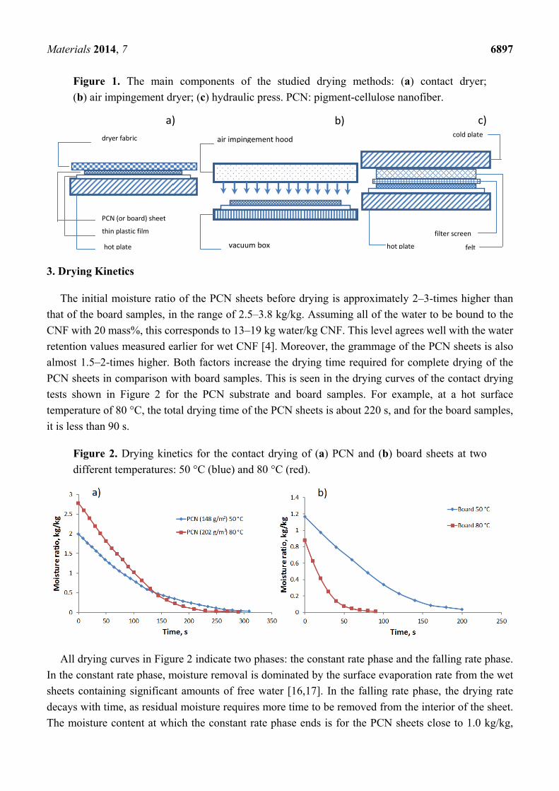
Materials 2014, 7 6897
Figure 1. The main components of the studied drying methods: (a) contact dryer;
(b) air impingement dryer; (c) hydraulic press. PCN: pigment-cellulose nanofiber.
3. Drying Kinetics
The initial moisture ratio of the PCN sheets before drying is approximately 2–3-times higher than
that of the board samples, in the range of 2.5–3.8 kg/kg. Assuming all of the water to be bound to the
CNF with 20 mass%, this corresponds to 13–19 kg water/kg CNF. This level agrees well with the water
retention values measured earlier for wet CNF [4]. Moreover, the grammage of the PCN sheets is also
almost 1.5–2-times higher. Both factors increase the drying time required for complete drying of the
PCN sheets in comparison with board samples. This is seen in the drying curves of the contact drying
tests shown in Figure 2 for the PCN substrate and board samples. For example, at a hot surface
temperature of 80 °C, the total drying time of the PCN sheets is about 220 s, and for the board samples,
it is less than 90 s.
Figure 2. Drying kinetics for the contact drying of (a) PCN and (b) board sheets at two
different temperatures: 50 °C (blue) and 80 °C (red).
All drying curves in Figure 2 indicate two phases: the constant rate phase and the falling rate phase.
In the constant rate phase, moisture removal is dominated by the surface evaporation rate from the wet
sheets containing significant amounts of free water [16,17]. In the falling rate phase, the drying rate
decays with time, as residual moisture requires more time to be removed from the interior of the sheet.
The moisture content at which the constant rate phase ends is for the PCN sheets close to 1.0 kg/kg,
PCN (or board) sheet
thin plastic film
hot plate
dryer fabric
a)air impingement hood
vacuum box
b)
felt
filter screen
cold plate
hot plate
c)
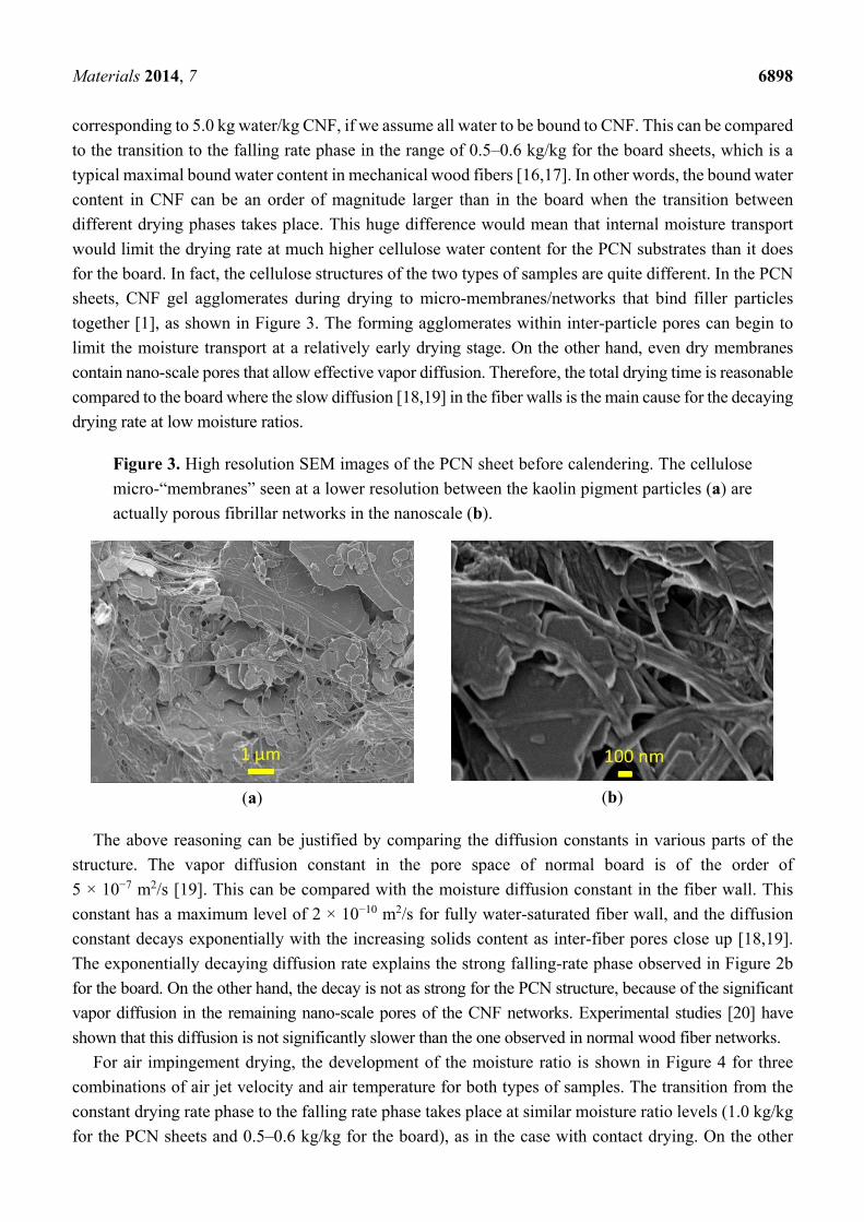
Materials 2014, 7 6898
corresponding to 5.0 kg water/kg CNF, if we assume all water to be bound to CNF. This can be compared
to the transition to the falling rate phase in the range of 0.5–0.6 kg/kg for the board sheets, which is a
typical maximal bound water content in mechanical wood fibers [16,17]. In other words, the bound water
content in CNF can be an order of magnitude larger than in the board when the transition between
different drying phases takes place. This huge difference would mean that internal moisture transport
would limit the drying rate at much higher cellulose water content for the PCN substrates than it does
for the board. In fact, the cellulose structures of the two types of samples are quite different. In the PCN
sheets, CNF gel agglomerates during drying to micro-membranes/networks that bind filler particles
together [1], as shown in Figure 3. The forming agglomerates within inter-particle pores can begin to
limit the moisture transport at a relatively early drying stage. On the other hand, even dry membranes
contain nano-scale pores that allow effective vapor diffusion. Therefore, the total drying time is reasonable
compared to the board where the slow diffusion [18,19] in the fiber walls is the main cause for the decaying
drying rate at low moisture ratios.
Figure 3. High resolution SEM images of the PCN sheet before calendering. The cellulose
micro-“membranes” seen at a lower resolution between the kaolin pigment particles (a) are
actually porous fibrillar networks in the nanoscale (b).
(a)
(b)
The above reasoning can be justified by comparing the diffusion constants in various parts of the
structure. The vapor diffusion constant in the pore space of normal board is of the order of
5 × 10⁻⁷ m2/s [19]. This can be compared with the moisture diffusion constant in the fiber wall. This
constant has a maximum level of 2 × 10⁻¹⁰ m2/s for fully water-saturated fiber wall, and the diffusion
constant decays exponentially with the increasing solids content as inter-fiber pores close up [18,19].
The exponentially decaying diffusion rate explains the strong falling-rate phase observed in Figure 2b
for the board. On the other hand, the decay is not as strong for the PCN structure, because of the significant
vapor diffusion in the remaining nano-scale pores of the CNF networks. Experimental studies [20] have
shown that this diffusion is not significantly slower than the one observed in normal wood fiber networks.
For air impingement drying, the development of the moisture ratio is shown in Figure 4 for three
combinations of air jet velocity and air temperature for both types of samples. The transition from the
constant drying rate phase to the falling rate phase takes place at similar moisture ratio levels (1.0 kg/kg
for the PCN sheets and 0.5–0.6 kg/kg for the board), as in the case with contact drying. On the other
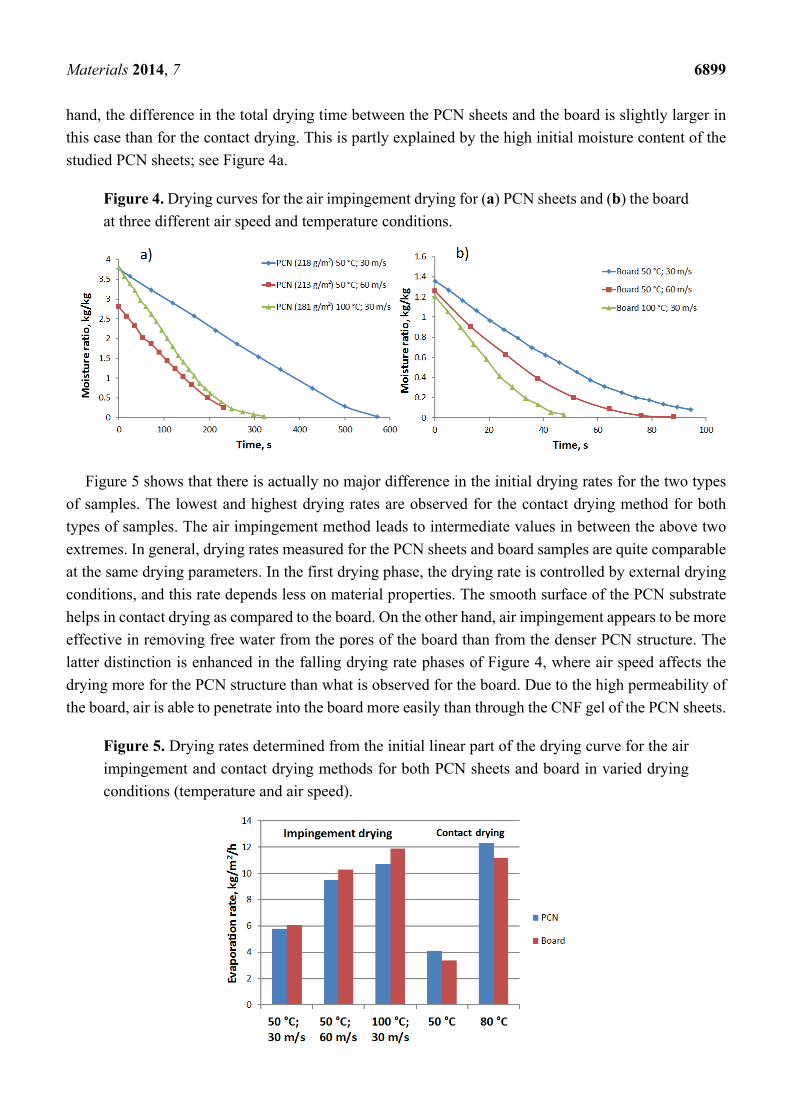
Materials 2014, 7 6899
hand, the difference in the total drying time between the PCN sheets and the board is slightly larger in
this case than for the contact drying. This is partly explained by the high initial moisture content of the
studied PCN sheets; see Figure 4a.
Figure 4. Drying curves for the air impingement drying for (a) PCN sheets and (b) the board
at three different air speed and temperature conditions.
Figure 5 shows that there is actually no major difference in the initial drying rates for the two types
of samples. The lowest and highest drying rates are observed for the contact drying method for both
types of samples. The air impingement method leads to intermediate values in between the above two
extremes. In general, drying rates measured for the PCN sheets and board samples are quite comparable
at the same drying parameters. In the first drying phase, the drying rate is controlled by external drying
conditions, and this rate depends less on material properties. The smooth surface of the PCN substrate
helps in contact drying as compared to the board. On the other hand, air impingement appears to be more
effective in removing free water from the pores of the board than from the denser PCN structure. The
latter distinction is enhanced in the falling drying rate phases of Figure 4, where air speed affects the
drying more for the PCN structure than what is observed for the board. Due to the high permeability of
the board, air is able to penetrate into the board more easily than through the CNF gel of the PCN sheets.
Figure 5. Drying rates determined from the initial linear part of the drying curve for the air
impingement and contact drying methods for both PCN sheets and board in varied drying
conditions (temperature and air speed).
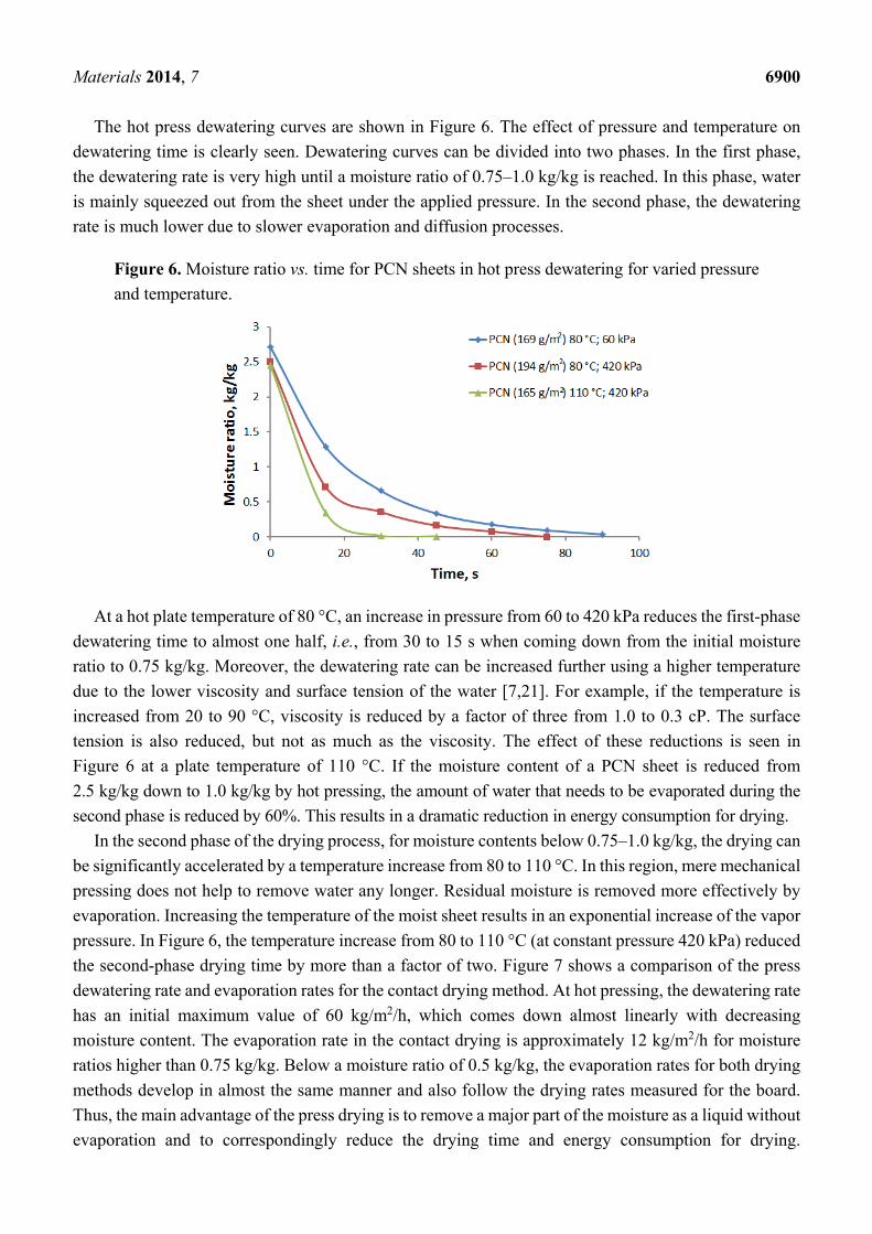
Materials 2014, 7 6900
The hot press dewatering curves are shown in Figure 6. The effect of pressure and temperature on
dewatering time is clearly seen. Dewatering curves can be divided into two phases. In the first phase,
the dewatering rate is very high until a moisture ratio of 0.75–1.0 kg/kg is reached. In this phase, water
is mainly squeezed out from the sheet under the applied pressure. In the second phase, the dewatering
rate is much lower due to slower evaporation and diffusion processes.
Figure 6. Moisture ratio vs. time for PCN sheets in hot press dewatering for varied pressure
and temperature.
At a hot plate temperature of 80 °C, an increase in pressure from 60 to 420 kPa reduces the first-phase
dewatering time to almost one half, i.e., from 30 to 15 s when coming down from the initial moisture
ratio to 0.75 kg/kg. Moreover, the dewatering rate can be increased further using a higher temperature
due to the lower viscosity and surface tension of the water [7,21]. For example, if the temperature is
increased from 20 to 90 °C, viscosity is reduced by a factor of three from 1.0 to 0.3 cP. The surface
tension is also reduced, but not as much as the viscosity. The effect of these reductions is seen in
Figure 6 at a plate temperature of 110 °C. If the moisture content of a PCN sheet is reduced from
2.5 kg/kg down to 1.0 kg/kg by hot pressing, the amount of water that needs to be evaporated during the
second phase is reduced by 60%. This results in a dramatic reduction in energy consumption for drying.
In the second phase of the drying process, for moisture contents below 0.75–1.0 kg/kg, the drying can
be significantly accelerated by a temperature increase from 80 to 110 °C. In this region, mere mechanical
pressing does not help to remove water any longer. Residual moisture is removed more effectively by
evaporation. Increasing the temperature of the moist sheet results in an exponential increase of the vapor
pressure. In Figure 6, the temperature increase from 80 to 110 °C (at constant pressure 420 kPa) reduced
the second-phase drying time by more than a factor of two. Figure 7 shows a comparison of the press
dewatering rate and evaporation rates for the contact drying method. At hot pressing, the dewatering rate
has an initial maximum value of 60 kg/m2/h, which comes down almost linearly with decreasing
moisture content. The evaporation rate in the contact drying is approximately 12 kg/m2/h for moisture
ratios higher than 0.75 kg/kg. Below a moisture ratio of 0.5 kg/kg, the evaporation rates for both drying
methods develop in almost the same manner and also follow the drying rates measured for the board.
Thus, the main advantage of the press drying is to remove a major part of the moisture as a liquid without
evaporation and to correspondingly reduce the drying time and energy consumption for drying.
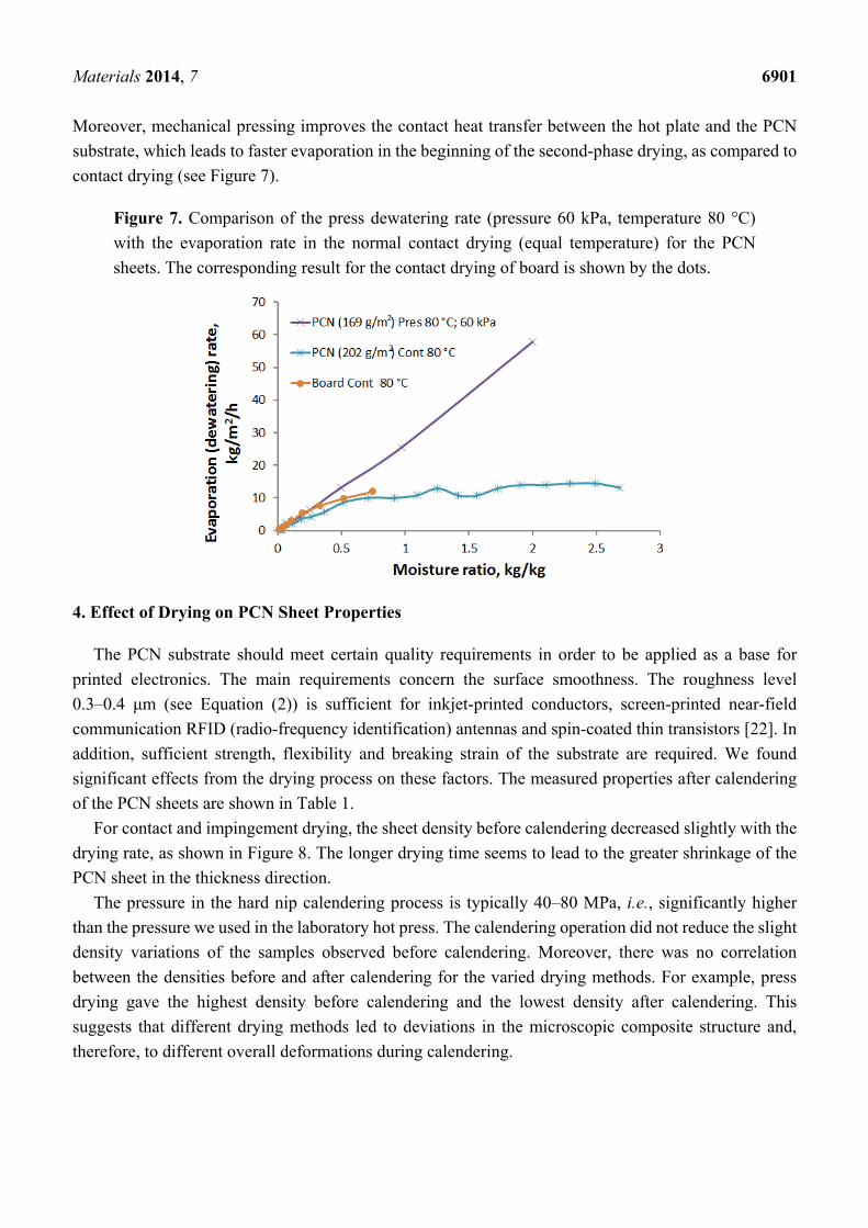
Materials 2014, 7 6901
Moreover, mechanical pressing improves the contact heat transfer between the hot plate and the PCN
substrate, which leads to faster evaporation in the beginning of the second-phase drying, as compared to
contact drying (see Figure 7).
Figure 7. Comparison of the press dewatering rate (pressure 60 kPa, temperature 80 °C)
with the evaporation rate in the normal contact drying (equal temperature) for the PCN
sheets. The corresponding result for the contact drying of board is shown by the dots.
4. Effect of Drying on PCN Sheet Properties
The PCN substrate should meet certain quality requirements in order to be applied as a base for
printed electronics. The main requirements concern the surface smoothness. The roughness level
0.3–0.4 μm (see Equation (2)) is sufficient for inkjet-printed conductors, screen-printed near-field
communication RFID (radio-frequency identification) antennas and spin-coated thin transistors [22]. In
addition, sufficient strength, flexibility and breaking strain of the substrate are required. We found
significant effects from the drying process on these factors. The measured properties after calendering
of the PCN sheets are shown in Table 1.
For contact and impingement drying, the sheet density before calendering decreased slightly with the
drying rate, as shown in Figure 8. The longer drying time seems to lead to the greater shrinkage of the
PCN sheet in the thickness direction.
The pressure in the hard nip calendering process is typically 40–80 MPa, i.e., significantly higher
than the pressure we used in the laboratory hot press. The calendering operation did not reduce the slight
density variations of the samples observed before calendering. Moreover, there was no correlation
between the densities before and after calendering for the varied drying methods. For example, press
drying gave the highest density before calendering and the lowest density after calendering. This
suggests that different drying methods led to deviations in the microscopic composite structure and,
therefore, to different overall deformations during calendering.
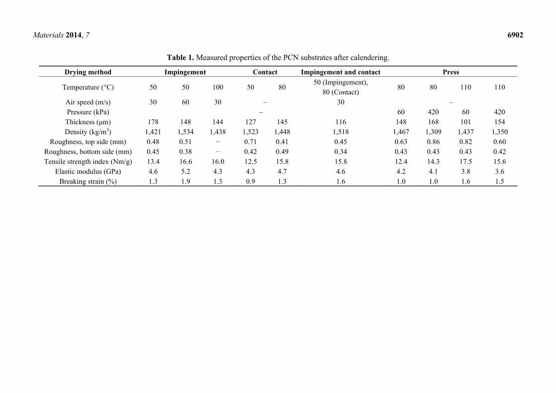
Materials 2014, 7 6902
Table 1. Measured properties of the PCN substrates after calendering.
Drying method Impingement Contact Impingement and contact Press
Temperature (°C) 50 50 100 50 80 50 (Impingement),
80 (Contact) 80 80 110 110
Air speed (m/s) 30 60 30 – 30 – Pressure (kPa) – 60 420 60 420 Thickness (μm) 178 148 144 127 145 116 148 168 101 154 Density (kg/m3) 1,421 1,534 1,438 1,523 1,448 1,518 1,467 1,309 1,437 1,350
Roughness, top side (mm) 0.48 0.51 − 0.71 0.41 0.45 0.63 0.86 0.82 0.60 Roughness, bottom side (mm) 0.45 0.38 − 0.42 0.49 0.34 0.43 0.43 0.43 0.42 Tensile strength index (Nm/g) 13.4 16.6 16.0 12.5 15.8 15.8 12.4 14.3 17.5 15.6
Elastic modulus (GPa) 4.6 5.2 4.3 4.3 4.7 4.6 4.2 4.1 3.8 3.6 Breaking strain (%) 1.3 1.9 1.3 0.9 1.3 1.6 1.0 1.0 1.6 1.5
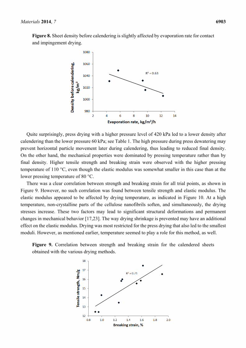
Materials 2014, 7 6903
Figure 8. Sheet density before calendering is slightly affected by evaporation rate for contact
and impingement drying.
Quite surprisingly, press drying with a higher pressure level of 420 kPa led to a lower density after
calendering than the lower pressure 60 kPa; see Table 1. The high pressure during press dewatering may
prevent horizontal particle movement later during calendering, thus leading to reduced final density.
On the other hand, the mechanical properties were dominated by pressing temperature rather than by
final density. Higher tensile strength and breaking strain were observed with the higher pressing
temperature of 110 °C, even though the elastic modulus was somewhat smaller in this case than at the
lower pressing temperature of 80 °C.
There was a clear correlation between strength and breaking strain for all trial points, as shown in
Figure 9. However, no such correlation was found between tensile strength and elastic modulus. The
elastic modulus appeared to be affected by drying temperature, as indicated in Figure 10. At a high
temperature, non-crystalline parts of the cellulose nanofibrils soften, and simultaneously, the drying
stresses increase. These two factors may lead to significant structural deformations and permanent
changes in mechanical behavior [17,23]. The way drying shrinkage is prevented may have an additional
effect on the elastic modulus. Drying was most restricted for the press drying that also led to the smallest
moduli. However, as mentioned earlier, temperature seemed to play a role for this method, as well.
Figure 9. Correlation between strength and breaking strain for the calendered sheets
obtained with the various drying methods.
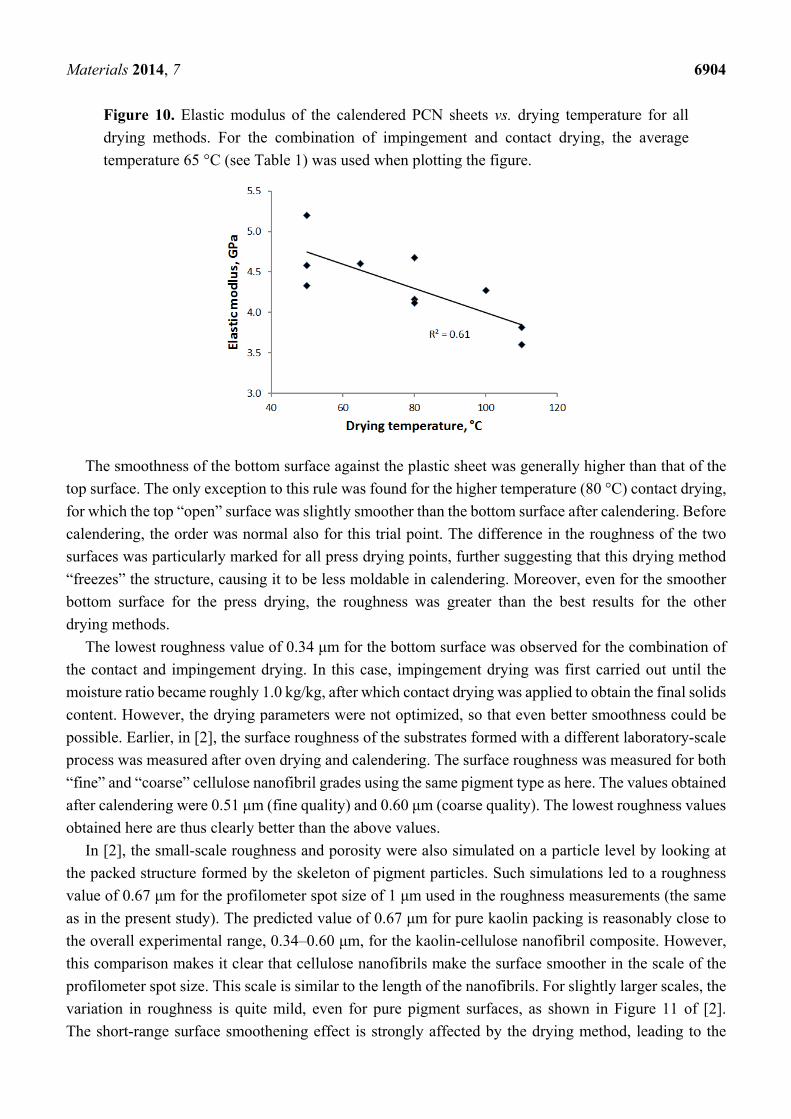
Materials 2014, 7 6904
Figure 10. Elastic modulus of the calendered PCN sheets vs. drying temperature for all
drying methods. For the combination of impingement and contact drying, the average
temperature 65 °C (see Table 1) was used when plotting the figure.
The smoothness of the bottom surface against the plastic sheet was generally higher than that of the
top surface. The only exception to this rule was found for the higher temperature (80 °C) contact drying,
for which the top “open” surface was slightly smoother than the bottom surface after calendering. Before
calendering, the order was normal also for this trial point. The difference in the roughness of the two
surfaces was particularly marked for all press drying points, further suggesting that this drying method
“freezes” the structure, causing it to be less moldable in calendering. Moreover, even for the smoother
bottom surface for the press drying, the roughness was greater than the best results for the other
drying methods.
The lowest roughness value of 0.34 μm for the bottom surface was observed for the combination of
the contact and impingement drying. In this case, impingement drying was first carried out until the
moisture ratio became roughly 1.0 kg/kg, after which contact drying was applied to obtain the final solids
content. However, the drying parameters were not optimized, so that even better smoothness could be
possible. Earlier, in [2], the surface roughness of the substrates formed with a different laboratory-scale
process was measured after oven drying and calendering. The surface roughness was measured for both
“fine” and “coarse” cellulose nanofibril grades using the same pigment type as here. The values obtained
after calendering were 0.51 μm (fine quality) and 0.60 μm (coarse quality). The lowest roughness values
obtained here are thus clearly better than the above values.
In [2], the small-scale roughness and porosity were also simulated on a particle level by looking at
the packed structure formed by the skeleton of pigment particles. Such simulations led to a roughness
value of 0.67 μm for the profilometer spot size of 1 μm used in the roughness measurements (the same
as in the present study). The predicted value of 0.67 μm for pure kaolin packing is reasonably close to
the overall experimental range, 0.34–0.60 μm, for the kaolin-cellulose nanofibril composite. However,
this comparison makes it clear that cellulose nanofibrils make the surface smoother in the scale of the
profilometer spot size. This scale is similar to the length of the nanofibrils. For slightly larger scales, the
variation in roughness is quite mild, even for pure pigment surfaces, as shown in Figure 11 of [2].
The short-range surface smoothening effect is strongly affected by the drying method, leading to the
Materials 2014, 7 6905
above relatively large variation of the roughness values. The drying rate probably affects the size and
density of the nanofibril clusters responsible for smoothing out the pigment surfaces and their edges.
5. Conclusions
In laboratory-scale experiments, it was shown that the PCN substrate can be dried using conventional
drying methods, such as contact drying and air impingement drying methods. Despite the very large
bound water content of the CNF gel, the estimated drying rates for the PCN substrate are comparable
with the drying rates of typical board with the same external drying conditions. The CNF agglomerates
seem to affect the moisture transport in an early drying stage, but for the low moisture ratios, nano-scale
pores in the CNF membranes/networks speed up vapor diffusion, as compared to the moisture diffusion
in the fiber walls within the board.
It was also demonstrated that, before drying, the water can be effectively removed from the PCN
sheets by hot pressing. Removal of water mechanically in the hot press will dramatically reduce the
energy consumption required for drying of an initially very wet PCN substrate.
The final properties of the PCN sheets after calendering could be significantly affected by the drying
method. Unfortunately, hot pressing led to somewhat unconformable structures with poorer surface
smoothness than with the other drying methods. The best smoothness of all of the drying methods was
obtained with a combination of impingement and contact drying. Mere contact drying led to an almost
equally smooth surface. The required smoothness level [22] for various applications, like inkjet-printed
conductors, screen-printed near-field communication RFID antennas and spin-coated thin transistors,
was achieved with both methods. By fine tuning the forming and drying processes (e.g., temperature, air
speed), the substrate properties could be probably further optimized. In this development, one should
take into account that the drying method and temperature affect the mechanical properties of the PCN
sheets, in addition to the surface properties.
Author Contributions
Oleg Timofeev carried out the drying tests. Katariina Torvinen and Jenni Sievänen produced the PCN
materials and prepared the SutCo pilot webs together with Timo Kaljunen. Jarmo Kouko was responsible
for the mechanical testing. Jukka Ketoja contributed to the analysis and interpretation of the results.
Conflicts of Interest
The authors declare no conflict of interest.
References
1. Torvinen, K.; Sievänen, J.; Hjelt, T.; Hellén, E. Smooth and flexible filler-nanocellulose composite
structure for printed electronics applications. Cellulose 2012, 19, 821–829.
2. Penttilä, A.; Sievänen, J.; Torvinen, K.; Ojanperä, K.; Ketoja, J.A. Filler-nanocellulose substrate
for printed electronics: Experiments and model approach to structure and conductivity. Cellulose
2013, 20, 1413–1424.
Materials 2014, 7 6906
3. Rantanen, J.; Lahtinen, P.; Maloney, T. Property space for fibre, microfibrillar cellulose and
precipitated CaCO3 composite sheets. Int. Pap. IPW 2013, 5, 46–51.
4. Dimic-Misic, K.; Puisto, A.; Paltakari, J.; Alava, M.; Maloney, T. The influence of shear on the
dewatering of high consistency nanofibrillated cellulose furnishes. Cellulose 2013, 20, 1853–1864.
5. Peng, Y.; Gardner, D.J.; Han, Y. Drying cellulose nanofibrils: In search of a suitable method.
Cellulose 2012, 19, 91–102.
6. Peng, Y.; Gardner, D.J.; Han, Y.; Kiziltas, A.; Cai, Z.; Tshabalala, M.A. Influence of drying method
on the material properties of nanocellulose I: Thermostability and crystallinity. Cellulose 2013, 20,
2379–2392.
7. Walker, K. Advances in hot pressing technology. Tappi J. 1990, 73, 99–101.
8. Timofeev, O.; Belski, A.; Mujumdar, A. Effect of dryer fabric pressure on multi-cylinder drying of
paper. In Drying of Solids; Mujumdar, A.S., Ed.; Science Publishers, Inc: Enfield, NH, USA, 1999;
pp. 221–237.
9. Asensio, C.; Seyed-Yagoobi, J.; Lehtinen, J.; Karlsson, M.; Timofeev, O.; Juppi, K. Comparison of
several multi-cylinder paper drying simulation models. Dry. Technol. 1995, 13, 945–958.
10. Kiiskinen, H.; Juppi, K.; Timofeev, O.; Karlsson, M.; Edelmann, K. Impingement drying of
multi-ply linerboard. Pulp Pap. Can. 1999, 100, T8–T10.
11. Lehtinen, J. Condebelt drying of paper and paperboard for optimizing quality and production for
many grades. Dry. Technol. 1995, 13, 2049–2068.
12. Timofeev, O.; Ilomäki, J.; Kuusela, J. Effect of process parameters on paper temperature in
Condebelt drying. In Proceedings of the 14th International Drying Symposium (IDS 2004),
Sao Paulo, Brazil, 22–25 August 2004; pp. 1327–1334.
13. Paper and Board—Determination of Grammage; ISO 536:1995; International Organization for
Standardization: Geneva, Switzerland, 1995.
14. Determination of Thickness and Bulk Density or Apparent Sheet Density; ISO 534:1998;
International Organization for Standardization: Geneva, Switzerland, 1998.
15. Lipponen, P.; Kouko, J.; Leppänen, T.; Hämäläinen, J. Elasto-plastic approach for paper cockling
phenomenon: On the importance of moisture gradient. Int. J. Solids Struct. 2008, 45, 3596–3609.
16. Weise, U.; Maloney, T.; Paulapuro, H. Quantification of water in different states of interaction with
wood pulp fibres. Cellulose 1996, 3, 189–202.
17. Niskanen, K. Paper Physics, 2nd ed.; Finnish Paper Engineers’ Association/Paperi ja Puu Oy: Helsinki,
Finland, 2008.
18. Topgaard, D.; Söderman, O. Diffusion of water absorbed in cellulose fibers studied with 1H-NMR.
Langmuir 2001, 17, 2694–2702.
19. Gupta, H.; Chatterjee, S.G. Parallel diffusion of moisture in paper. Part 1: Steady-state conditions.
Ind. Eng. Chem. Res. 2003, 42, 6582–6592.
20. Huang, B.; Hill, R.; van de Ven, T. Nanopaper: Thin films prepared from polymeric nanotubes.
Macromol. Mater. Eng. 2012, 297, 821–830.
21. Paulapuro, H. Papermaking Part 1, Stock Preparation and Wet End, 2nd ed.; Finnish Paper
Engineers’ Association/Paperi ja Puu Oy: Helsinki, Finland, 2008.
Materials 2014, 7 6907
22. Torvinen, K.; Sievänen, J.; Hassinen, T.; Mattila, T.; Hellén, E. Flexible pigment-nanocellulose
substrate for printed electronics with good thermal tolerance. In Proceedings of the 1st International
Symposium on Nanoparticles/Nanomaterials and Applications, Caparica-Almada, Portugal,
20–22 January 2014.
23. Paavilainen, S., McWhirter, J.L.; Róg, T.; Järvinen, J.; Vattulainen, I.; Ketoja, J.A. Mechanical
properties of cellulose nanofibrils determined through atomistic molecular dynamics simulations.
Nordic Pulp Pap. Res. J. 2012, 27, 282–286.
© 2014 by the authors; licensee MDPI, Basel, Switzerland. This article is an open access article
distributed under the terms and conditions of the Creative Commons Attribution license
(http://creativecommons.org/licenses/by/4.0/).
PAPER IV
Pigment-cellulose nanofibril compositeand its application as a separator-
substrate in printed supercapacitors
Electronic Materials Letters 11, 1040–1047.Copyright 2015 KIM and Springer.
Reprinted with permission from the publisher.
PAPER V
Nanoporous kaolin – cellulose nanofibrilcomposites for printed electronics
Flexible and Printed Electronics, Volume 2, Number 2,Focus on Paper Electronics, 11 p.
Copyright 2017 IOP Publishing Ltd.Reprinted with permission from the publisher.
rebmun dna eltit seireS
TTV ecneicS 261
eltiT setisopmoc lirbfionan esolullec-tnemgip elbixelF snoitacilppa scinortcele detnirp rof
)s(rohtuA nenivroT aniirataK
tcartsbA esolullec fo esu levon fo seitilibissop eht dnapxe ot saw krow siht fo mia ehT ni hcaorppa wen ehT .setisopmoc desab-oib rof )FNMC( slirbfionan dna -orcim
egnar ediw ylevitaler a ni FNMC dna stnemgip cinagroni enibmoc ot saw krow siht dna -orcim esolullec-tnemgip– fo noitareneg eht rof snoitanibmoc tnenopmoc fo
deirav seiduts eseht ni FNMC fo tnuoma ehT .setisopmoc )FNMCP( lirbfionan krow eht fo sucof niam ehT .setisopmoc deiduts eht ni %-tw 05 dna 02 neewteb
eht dna desu slairetam war eht neewteb pihsnoitaler eht gniyfiralc no saw dna ssenhtooms sa hcus ,tcudorp lanfi eht fo seitreporp larutcurts etisopmoc
etisopmoc eht no spets ssecorp gnirutcafunam fo ecneuflni ehT .ytisorop ehT .elacs tolip-imes dna yrotarobal htob ni yllatnemirepxe deiduts saw seitreporp mlfi yb dna elacs yrotarobal ni noitartlfi muucav yb derutcafunam erew setisopmoc
dna ,gniyrd ,gnisserp tew yb dewollof sesac htob ni ,elacs tolip-imes ni gnitsac elcyc-efil dna cimonoce-onhcet gnidulcni seiduts ytilibisaef no desaB .gnirednelac
htiw derutpac eb nac stekram dna seitinutroppo tcudorp wen ,tnemssessa .snoitacilppa scinortcele detnirp rof setisopmoc FNMCP
,evitceffe-tsoc ,elbixefl fo noitcudorp eht rof deen gniworg a syadawon si erehT
FNMC .snoitacilppa scinortcele detnirp rof setartsbus yldneirf yllatnemnorivne dna ,krow siht nI .dlefi siht ni tseretni tnacfiingis detcartta sah lairetam war a sa
ot serutcurts tpecnoc-fo-foorp sa derutcafunam erew secived lanoitcnuf tnereffid scinortcele detnirp rof setisopmoc depoleved eht fo ytilibasu eht etartsnomed
-revlis a htiw gnitnirp tej-kni )1 :erew stpecnoc-fo-foorp deiduts ehT .snoitacilppadetnirp rof etartsbus rotarapes lanoitcnuf-elbuod )2 ,kni elcitraponan
)4 dna ,etartsbus eht no detisoped rotsisnart detaludom-noi na )3 ,sroticapacrepus ycneuqerf oidar laicremmoc a dna kni revlis gnisu sannetna detnirp neercs
raen lanoitcnuf a sa niser yxope revlis a gnisu dehcatta pihc )DIFR( noitacfiitnedi .etartsbus eht no gat DIFR noitacinummoc dlefi
krowten FNMC-tnemgip suoroponan a evah setisopmoc FNMCP depoleved ehT etartsbus deriuqer ehT .seitreporp noitprosba kni dellortnoc swolla taht erutcurts
,kni ,dohtem gnitnirp desu eht no dneped ylgnorts ssenhtooms dna ytisorop etartsbus elbaniatsus a reffo setisopmoc FNMCP ehT .ngised ecived dna ,tnevlos yrev ylno taht serutarepmet hgih ta desu eb ot snoitacilppa scinortcele detnirp rof
.dnatshtiw yltnerruc nac smlfi citsalp laiceps
NRU ,NSSI ,NBSI NBSI 7-1758-83-159-879 ).de kcab tfoS( NBSI 0-0758-83-159-879 )snoitacilbup/tcapmi/moc.hcraeserttv.www//:ptth :LRU(
L-NSSI X911-2422 NSSI X911-2422 )tnirP( NSSI 3021-2422 )enilnO(
:NBSI:NRU/fi.nru//:ptth 0-0758-83-159-879
etaD 7102 rebotcO
egaugnaL tcartsba hsinniF ,hsilgnE
segaP .p 76 .ppa + .p 19
tcejorp eht fo emaN
yb denoissimmoC
sdrowyeK etisopmoc ,esolulleconan ,slirbfiorcim esolullec ,slirbfionan esolullec etartsbus ,dohtem gnitsac ,tnemgip larenim ,scinortcele detnirp ,smlfi
rehsilbuP dtL dnalniF fo ertneC hcraeseR lacinhceT TTV 111 227 020 .leT ,dnalniF ,TTV 44020-IF ,0001 xoB .O.P
oremun aj ajras nusiakluJ
TTV ecneicS 261
ekemiN titiisopmokasoolullesonan-ittnemgip tavatsuoJ niiskullevos nakiinortkele nuteniap
)t(äjikeT nenivroT aniirataK
ämletsiviiT nejotsula netsillävätsyötsiräpmy aj nediakkohetsunnatsuk ,neivatsuoJ .evrat avavsak assiskullevos nakiinortkele nuteniap no neesimattout
.allala ällät atsutsonniik äävättikrem tynättäreh aneenia-akaar no asoolullesonaN
neillirbfiasoolullesonan aj -orkim aatnejaal ilo aneettiovat nöyt nämäT äätnydöyh naadiov atioj ,assietnekarittiisopmok assisiamovlak ättyyvättetyäk
asseskumiktuT .assiskullevosetoutuppol nakiinortkele nuteniap assisuu nesippyytneduu aasoolullesonan aj äjettnemgip aisinaagroäpe niittetsidhy
suuso nasoolullesonan nytetyäK .iskesimatsimlav najhopilaairetam .% 05 - 02 älliläv assietnekarittiisopmok assiutiktut ilethiav atsoniapsianokok
neettoutuppol aj nedienia-akaar nejyttetyäk äättivles ilo oniapääp nöyT ,neduusiokouh aj nedyelis netuk ,neiskuusianimo netsilleetnekar netsittiisopmok
.aiskutukiavorouv äisiläv
niittiktut niiskuusianimo neittiisopmok atsutukiav nediehiavissesorpsutsimlaV -tolip ätte alleskutadous allutetsieniapila assoirotarobal äkes itsesilleekok
tavisarues äimletenemotnatout aipmeloM .ällämletenemulavimlfi ässötsiräpmy .itnioretnalak änylettisäkikläj aj sutaviuk ,sutsirupäkräm
niittatset allioj ,ajettnenopmok aisilaanoitknuf aisialire niittetsimlav ässöyT .assiskullevosetoutuppol ättyyvättetyäk neilaairetam netsiamovlak nejyttetihek
)2 ,nidhoj uttetsolutukhiusetsum )1 tavilo ajetpesnok ajuttiktuT ellimlfi )3 ,anatsulaoniap ätte anovlaksutore äkes iimiot akoj ,irottaasnednokrepus
aj attetsumaepoh niittetyäk assoj ,innetna utteniap )4 aj irotsisnart utiossesorp netsullevoS .änyttetinniik niittiisopmok )DIFR( atsutsinnutsuujaatoidar atsillapuak
ätsytetyäk itsaakkamiov taviuppiir suusiokouh aj syelis natsula amitaav teduU .atsulettinnuus nissesorp aj atsemittouil ,atseetsum ,ätsämletenemoniap
atiekrok ,nesiakum neskytihek nävätsek tavaojrat titiisopmok tytetihek ässöyt .niiskullevos nakiinortkele nuteniap nusiaktarilaairetam nävätsek ajolitöpmäl
NRU ,NSSI ,NBSI NBSI 7-1758-83-159-879 ).din( NBSI 0-0758-83-159-879 )tusiakluj/fi.ttv.www//:ptth :LRU(
L-NSSI X911-2422 NSSI X911-2422 )utteniaP( NSSI 3021-2422 )usiaklujokkreV(
:NBSI:NRU/fi.nru//:ptth 0-0758-83-159-879
akiausiakluJ 7102 uukakoL
ileiK ämletsiviit nenileiknemous ,itnalgnE
äräämuviS .s 76 .ttiil + .s 19
imin nitkejorP
tajattiohaR
tanasniavA akkiinortkele utteniap ,atsula ,ittiisopmok ,ittnemgip ,ullesonan
ajisiakluJ yO TTV sukseksumiktut naigolonkeT 111 227 020 .hup ,TTV 44020 ,0001 LP
setisopmoc lirbfionan esolullec-tnemgip elbixelF snoitacilppa scinortcele detnirp rof
nenivroT aniirataK
,elbixefl fo noitcudorp eht rof deen gniworg a syadawon si erehT detnirp rof setartsbus yldneirf yllatnemnorivne dna ,evitceffe-tsoc
sa )FNMC( slirbfionan dna-orcim esolulleC .snoitacilppa scinortcele mia ehT .dlefi siht ni tseretni tnacfiingis detcartta sah lairetam war a
fo esu levon fo seitilibissop eht dnapxe ot saw krow siht fo .setisopmoc desab-oib rof )FNMC( slirbfionan dna -orcim esolullec stnemgip cinagroni enibmoc ot saw krow siht ni hcaorppa wen ehT
snoitanibmoc tnenopmoc fo egnar ediw ylevitaler a ni FNMC dna lirbfionan dna -orcim esolullec - tnemgip fo noitareneg eht rof
eht gniyfiralc no saw krow eht fo sucof niam ehT .setisopmoc etisopmoc eht dna desu slairetam war eht neewteb pihsnoitaler
dna ssenhtooms sa hcus ,tcudorp lanfi eht fo seitreporp larutcurts noitartlfi muucav yb derutcafunam erew setisopmoc ehT .ytisorop
htob ni ,elacs tolip-imes ni gnitsac mlfi yb dna elacs yrotarobal ni .gnirednelac dna ,gniyrd ,gnisserp tew yb dewollof sesac
sa derutcafunam erew secived lanoitcnuf tnereffid ,krow siht nI eht fo ytilibasu eht etartsnomed ot serutcurts tpecnoc-fo-foorp ehT .snoitacilppa scinortcele detnirp rof setisopmoc depoleved
-tnemgip suoroponan a evah setisopmoc FNMCP depolevednoitprosba kni dellortnoc swolla taht erutcurts krowten FNMC
ssenhtooms dna ytisorop etartsbus deriuqer ehT .seitreporp dna ,tnevlos ,kni ,dohtem gnitnirp desu eht no dneped ylgnorts
elbaniatsus a reffo setisopmoc FNMCP ehT .ngised ecived hgih ta desu eb ot snoitacilppa scinortcele detnirp rof etartsbus
yltnerruc nac smlfi citsalp laiceps yrev ylno taht serutarepmet .dnatshtiw
NBSI 7-1758-83-159-879 ).de kcab tfoS( NBSI 0-0758-83-159-879 :LRU( snoitacilbup/tcapmi/moc.hcraeserttv.www//:ptth )
X911-2422 L-NSSI X911-2422 NSSI )tnirP( 3021-2422 NSSI )enilnO(
:NBSI:NRU/fi.nru//:ptth 0-0758-83-159-879
E
CN
EIC
S T
TV
26
1 .
..r
of s
etis
op
mo
c li
rbi
fo
na
n es
olul
le
c-t
ne
mgi
p el
bix
elF
•VIS
ION
S•SCIENCE•TEC
HN
OL
OG
Y•RESEARCHHIGHLI
GH
TS
noitatressiD
261
esolullec-tnemgip elbixelF setisopmoc lirbfionanscinortcele detnirp rof
snoitacilppa
nenivroT aniirataK