ANGLE HEADS TÊTES A RENVOI D'ANGLE - Gerardi SPA · La tête à renvoi d'angle est livrée dans un...
48
LIBRO ISTRUZIONI INSTRUCTION BOOK MANUEL D' UTILISATION EVOLUTION LINE SERIES A TC TESTE ANGOLARI ANGLE HEADS TÊTES A RENVOI D'ANGLE Made in Italy
-
Upload
truonghanh -
Category
Documents
-
view
234 -
download
0
Transcript of ANGLE HEADS TÊTES A RENVOI D'ANGLE - Gerardi SPA · La tête à renvoi d'angle est livrée dans un...
LIBRO ISTRUZIONI INSTRUCTION BOOK MANUEL D' UTILISATION
EVOLUTION LINE SERIESATCT E S T E A N G O L A R I
A N G L E H E A D ST Ê T E S A R E N V O I D ' A N G L E
Made in Italy
2 Libro istruzioni / Instruction book / Manuel d'utilisation
EVOLUTION L INE
Pag / Page
PER CAMBIO UTENSILE AUTOMATICOAUTOMATIC TOOL CHANGECHANGEMENT D'OUTIL AUTOMATIQUE
FS90-4 / HSK80-110 F90-10 F90-16S F90-S40
F90-16L F90-16S / 2U F90-10 / 10bar FMU-16
Valigetta con dotazione standard Bag with standard equipment Valise avec équipements standard
WELCOMEBENVENUTO
ATC SERIES
3
TESTE ANGOLARI / ANGLE HEADS / TÊTES À RENVOI D'ANGLE
Libro istruzioni / Instruction book / Manuel d'utilisation
ATC SERIES
EVOLUTION L INE
Pag / Page
PER CAMBIO UTENSILE AUTOMATICOAUTOMATIC TOOL CHANGECHANGEMENT D'OUTIL AUTOMATIQUE
3 Libro istruzioni / Instruction book / Manuel d'utilisationPag / Page
Grazie per aver deciso di acquistare una testa ad angolo GERARDI SpA della serie EVOLUTION.Queste istruzioni per l'uso e la manutenzione hanno lo scopo di aiutarVi a prendere confidenza con la Vostra testa ad angolo. Vi consigliamo di leggerle e di conservarle per una successiva consultazione. Per le teste ad angolo di nostra costruzione Vi diamo un'assoluta garanzia riguardo alla selezione dei materiali, precisione delle lavorazioni e dimensionamento oltre alla capacità richiesta per una maggiore resistenza delle parti sollecitate.
Congratulations for having chosen an EVOLUTION LINE GERARDI SpA angle head the aim of these operating instructions is to help you to become acquainted with your angle head unit. We advise you to read them and keep them for future reference.Our angle head are fully guaranteed in terms of selected materials , tolerances and sizing as well as high standards for the greater strength of parts under stress.
Merci d'avoir choisi la tête à renvoi d'angle EVOLUTION LINE GERARDI SpA. Le but de ce manuel d'utilisation est de vous permettre de l'utiliser dans les meilleures conditions possibles. Nous vous conseillons de le lire attentivement et de le mettre de côté dans un endroit sûr. Nos têtes à renvoi d'angle sont fabriquées avec des critères de haute qualité en terme de matériaux, tolérances, dimensionnel et choix de composants. Ceci vous permet d'être tranquille en utilisant un matériel fiable et éprouvé.
Made in ItalyLa Gerardi SPA non si assume nessuna responsabilità riguardo a danni a persone, cose od alla testa angolare stessa derivanti da un uso improprio.Gerardi Spa cannot accept any liabilit for injury to persons or damage to things or to the angle head it self caused by improper machine use.Gerardi Spa n'acceptera aucun dégât ni blessure causé par un usage inapproprié.
WELCOMEBIENVENU
4
TESTE ANGOLARI / ANGLE HEADS / TÊTES À RENVOI D'ANGLE
Libro istruzioni / Instruction book / Manuel d'utilisation
ATC SERIES
EVOLUTION L INE
Pag / Page
PER CAMBIO UTENSILE AUTOMATICOAUTOMATIC TOOL CHANGECHANGEMENT D'OUTIL AUTOMATIQUE
INDICE / INDEX / SOMMAIRE
SIMBOLOGIA UTILIZZATA / SYMBOLS USED / SYMBOLES UTILISÉSNote generali / General notes / Notes generales
Pag 7
DESCRIZIONE GENERALE / GENERAL DESCRIPTION / DESCRIPTION GENERALEPag 9
PROCEDURE PER CAMBIO CONO - TESTA / OPERATIONS FOR ANGULAR HEAD SHANK EXCHANGE / OPERATIONS POUR CHANGER LE CÔNE DE LA TÊTE
Pag 10
UTILIZZO DELLA TESTA / ANGLE HEAD USE / TÊTE UTILISATIONPag 11
NORME DI SICUREZZA / SAFETY NORMS / NORMES DE SECURITEPag 12
CARATTERISTICHE TECNICHE / TECHNICAL SPECIFICATIONS / SPECIFICATIONS TECHNIQUESPag 13
ACCESSORI / ACCESSORIES / ACCESSOIRESPag 16
DIAGRAMMI DI COPPIA E DI POTENZA / TORQUE AND POWER DIAGRAMS /DIAGRAMMES DE COUPLE ET DE PUISSANCE
Pag 19
IMBALLO - MOVIMENTAZIONE - STOCCAGGIO / PACKAGING - HANDLING - STORINGEMBALLAGE - CONDITIONS DE STOCKAGE
Pag 5
INTRODUZIONEINTRODUCTIONINTRODUCTION
Pag 38 UTILIZZO / USE / UTILISATION
Pag 30 ORIENTAMENTO TESTE FMU / FMU HEAD ORIENTATION / RÉGLAGE DE L' ORIENTATION DE LA TÊTE FMU
Pag 29 ORIENTAMENTO TESTA F90 / F90 HEAD ORIENTATION / ORIENTATION DE LA TÊTE F90
GARANZIA E PARTI DI RICAMBIO / WARRANTY AND SPARE PARTS / GARANTIE ET PIECES DETACHEESPag 46
GUIDA AL MONTAGGIO E CONNESSIONE MACCHINA / GUIDE TO ASSEMBLING AND MACHINE CONNECTION / MANUEL D'UTILISATION ET CONNECTION A' LA MACHINE
Pag 22
Pag 39 MONTAGGIO UTENSILI / FITTING TOOLS / MONTAGE DE L'OUTIL
Pag 35 REGOLAZIONI / ADJUSTEMENTS / REGLAGES Connessione impianto refrigerante / Connection to the coolant unit / Acheminement du fluide de coupe Avvertenze per l'installazione della testa / Precautions when fitting the head to the machine Précautions de montage de la tête à renvoi d'angle dans la machine
Pag 35Pag 37
Pag 40 MANUTENZIONE / MAINTENANCE / MAINTENANCE Inconvenienti e relativi rimedi / Troubleshooting / Problèmes Smantellamento / Scrapping / Mise au rebut
Pag 41Pag 45
ISTRUZIONI OPERATIVE - OPERATIVE INSTRUCTION - MODE D'EMPLOI
Pag 21 AVVIO / START-UP / DEMARRAGE Rodaggio / Run-In / Rodage
5
TESTE ANGOLARI / ANGLE HEADS / TÊTES À RENVOI D'ANGLE
Libro istruzioni / Instruction book / Manuel d'utilisation
ATC SERIES
EVOLUTION L INE
Pag / Page 5 Libro istruzioni / Instruction book / Manuel d'utilisationPag / Page
PER CAMBIO UTENSILE AUTOMATICOAUTOMATIC TOOL CHANGECHANGEMENT D'OUTIL AUTOMATIQUE
i ■ Nel caso si riscontrino anomalie evidenti non utilizzare la testa ad angolo, ma avvertire immediatamente il costruttore
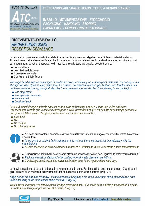
La testa ad angolo viene fornita imballata in scatole di cartone o in valigette con all’ interno materiali antiurto. Al ricevimento della stessa verificare che il contenuto corrisponda alle specifiche d'ordine e che non vi siano stati danneggiamenti dovuti al trasporto. Nell’ imballo, oltre alla testa ad angolo, dovete trovare:
■ Lo stop-block■ Le chiavi in dotazione■ Il presente manuale■ Confezione di lubrificante
The angle head is supplied packaged in cardboard boxes containing loose shockproof materials (cut paper) or in a shockproof case. Upon receipt, make sure the contents correspond to order specifications and that the head has not been damaged during transport. Besides the angle head you will also find the following in the packaging:
■ The stop-block■ The spanners provided■ This manual■ Lubricant pack
La tête à renvoi d'angle est livrée dans un carton avec du bourrage papier ou dans une valise anti-choc. Dès réception, vérifiez que le contenu correspond à votre commande et qu'il n'a pas été endommagé pendant le transport. La tête à renvoi d'angle est livrée avec les accessoires suivants :
■ Stop-block■ Clé■ Ce manuel■ Un tube de graisse
■ In the event of evident faults being found,do not use the angle head, but immediately notify the manufacturer.■ Si vous observez un défaut évident en déballant, n'utilisez pas la tête et contactez-nous immédiatement
■ L’eliminazione dell’imballo deve essere effettuata secondo le norme locali riguardo lo smaltimento dei rifiuti.■ Packaging must be disposed of according to local waste disposal regulations.■ L'emballage doit être jeté ou recyclé en fonction de la loi en vigueur dans votre pays.
La movimentazione delle teste ad angolo avviene manualmente. Per i modelli di peso superiore ai 10 kg si consi-glia l ’utilizzo di un mezzo di sollevamento idoneo secondo le istruzioni riportate (Pag. 37)Angle heads are handled manually. In case of models weighing over 10 kg, a suitable lifting mechanism is best used according to the instructions in this manual. (Pag. 37)Vous pouvez manipuler les têtes à renvoi d'angle manuellement. Pour celles dont le poids est supérieur à 10 kgs, un système de levage approprié doit être utilisé. (Pag. 37)
IMBALLO - MOVIMENTAZIONE - STOCCAGGIOPACKAGING - HANDLING - STORINGEMBALLAGE - CONDITIONS DE STOCKAGE
RICEVIMENTO-DISIMBALLORECEIPT-UNPACKINGRECEPTION-DEBALLAGE
6
TESTE ANGOLARI / ANGLE HEADS / TÊTES À RENVOI D'ANGLE
Libro istruzioni / Instruction book / Manuel d'utilisation
ATC SERIES
EVOLUTION L INE
Pag / Page
PER CAMBIO UTENSILE AUTOMATICOAUTOMATIC TOOL CHANGECHANGEMENT D'OUTIL AUTOMATIQUE
Si raccomanda di eseguire le operazioni di scarico, movimentazione e installazione nel rispetto della legislazione vigente in materia di sicurezza sul posto di lavoro.Always perform unloading, handling and installation operations in conformity with safety regulations in force at the place of work.Respectez toujours les règles en vigueur dans votre pays lorsque vous installez et enlevez la tête à renvoi d'angle de la machine.
Nel caso occorra immagazzinare il prodotto attenersi a quanto segue:■ Pulizia dagli eventuali residui di lavorazione.■ Proteggere le parti rettificate con pellicola di grasso e/o liquidi protettivi anticorrosione.■ Immagazzinare in un luogo fresco ed asciutto con temperature comprese fra i - 5° e + 40°C.■ Proteggere la testa ad angolo dallo sporco e dalla polvere.■ Se l’ immagazzinamento si prolunga oltre sei mesi, al riutilizzo è consigliata la sostituzione del grasso lubrificante (Pag. 40) ■ Pulizia dei condotti del refrigerante.
In the event of having to store the product, proceed as follows:■ Clean away any machining residues.■ Protect the ground parts with a film of grease and/or anticorrosion protective liquids.■ Store in cool and dry premises at temperatures between -5°C and +40°C.■ Protect the angle head against dirt and dust.■ If storage continues for over six months, the lubricating grease is best replaced before machine re-use (Pag. 40)■ Clean the coolant pipes.
Si vous êtes amené à stocker ce produit, procédez de la façon suivante:■ Nettoyez les résidus d'usinage.■ Protégez les parties rectifiées avec un film d'huile anti-corrosion.■ Stockez le produit dans un endroit sec à une température comprise entre -5°C et +40°C■ Protégez la tête de la rouille et de la saleté.■ Si vous stockez la tête à renvoi d'angle plus de 6 mois, il est préférable de changer la graisse avant de l'utiliser. (Pag. 40)■ Nettoyez les tuyaux de passage de lubrifiant.
IMBALLO - MOVIMENTAZIONE - STOCCAGGIOPACKAGING - HANDLING - STORINGEMBALLAGE - CONDITIONS DE STOCKAGE
RICEVIMENTO-DISIMBALLORECEPIT-UNPACKINGRECEPTION-DEBALLAGE
STOCCAGGIOSTORINGSTOCKAGE
7
TESTE ANGOLARI / ANGLE HEADS / TÊTES À RENVOI D'ANGLE
Libro istruzioni / Instruction book / Manuel d'utilisation
ATC SERIES
EVOLUTION L INE
Pag / Page 7 Libro istruzioni / Instruction book / Manuel d'utilisationPag / Page
PER CAMBIO UTENSILE AUTOMATICOAUTOMATIC TOOL CHANGECHANGEMENT D'OUTIL AUTOMATIQUE
PericoloDangerDanger
Tutte le operazioni contrassegnate da questo simbolo vanno eseguite con la massima attenzione per quanto riguarda le norme disicurezza (Pag. 10).All the operations marked by this symbol must be performed with the most care as regards the safety norms (Pag. 10).Toutes les opérations précédées de ce symbole doivent être exécutées avec le plus de précautions possibles en respectant les normes de sécurité (Pag. 10).
i AvvertenzaImportantImportant
Tutte le operazioni contrassegnate da questo simbolo vanno eseguite con la massima attenzione.Il mancato rispetto di tali norme può causare danni e malfunzionamenti alla testa ad angolo. Inoltre tale simbolo identifica operazioni sulle quali è necessario richiamare l’attenzione di chi legge.All the operations marked by this symbol must be performed with the most care. Failure to comply with these norms could cause damage and faults to the angle head. This symbol also identifies operations requiring the special attention of the reader.Toutes les opérations précédées de ce symbole doivent être exécutées avec le plus de précautions possibles. Si vous ne le faites pas suivant les normes, cela peut endommager la tête.Ce symbole demande également une attention particulière de la part du lecteur.
InterventoAdjustmentAjustement
Tutte le operazioni contrassegnate da questo simbolo vanno effettuate da persone qualificate per interventi su componenti meccanici.All operations marked by this symbol must be carried out by persons trained to perform jobs on mechanical component parts.Toutes les opérations précédées de ce symbole doivent être réalisées par une personne compétente en mécanique.
AttaccoConnector
CôneForaturaDrillingPerçage
MaschiaturaTapping
TaraudageRapporto
RatioRéductionVelocita'SpeedVitesse
PesoWeightPoids
RotazioneRotationRotation
Tipo di attacco disponibile per la connessione alla macchina.Type of connector available for machine connection.Cône disponible pour l'adaptation sur la machine.
Capacità massima di foratura.Maximum drilling capacity of angle head.Capacité maxi en perçage de la tête à renvoi d'angle.
Capacità massima di maschiatura.Maximum tapping capacity of angle head.Capacité maxi en taraudage de la tête à renvoi d'angle.
Rapporto entrata-uscita della testa ad angolo.Angle head in-out ratio.Rapport de réduction.
Velocità massima in uscita, in giri al minuto.Maximum exit speedof anglehead, in RPM.Vitesse maxi autorisée en sortie de broche.
Peso della testa, in kgWeight of angle head, in kg.Poids de la tête en kilo.
Senso di rotazione.Rotation direction.Sens de rotation.
PressionePressurePression
Pressione max, in bar del refrigeranteMaximum pressure of the coolant, in bar.Pression maxi du lubrifiant, en bar.
SIMBOLOGIA UTILIZZATASYMBOLS USED SYMBOLES UTILISES
ImballaggioPackagingEmballage
Lo smaltimento deve essere effettuato secondo le norme locali sullo smaltimento rifiuti. Disposed of according to local waste disposal regulations.Jeté ou recyclé en fonction de la loi en vigueur dans votre pays.
AX LOAD
10BAR
TORQUE
WEIGHT
DRILL
TAP
70 BAR
SPEED
AX LOAD
10BAR
TORQUE
WEIGHT
DRILL
TAP
70 BAR
SPEED
AX LOAD
10BAR
TORQUE
WEIGHT
DRILL
TAP
70 BAR
SPEED
AX LOAD
10BAR
TORQUE
WEIGHT
DRILL
TAP
70 BAR
SPEED
AX LOAD
10BAR
TORQUE
WEIGHT
DRILL
TAP
70 BAR
SPEED
8
TESTE ANGOLARI / ANGLE HEADS / TÊTES À RENVOI D'ANGLE
Libro istruzioni / Instruction book / Manuel d'utilisation
ATC SERIES
EVOLUTION L INE
Pag / Page
PER CAMBIO UTENSILE AUTOMATICOAUTOMATIC TOOL CHANGECHANGEMENT D'OUTIL AUTOMATIQUE
i ■ Una corretta installazione. ■ Manutenzione e cura scrupolosa nell'uso del prodotto.■ Leggere con attenzione il presente manuale prima di procedere con la messa in servizio della testa ad angolo.■ Il manuale è stato realizzato con lo scopo di fornire all'utilizzatore tutte le informazioni inerenti l'aspetto tecnico, l'installazione, la regolazione, l'uso e la manutenzione della testa acquistata. Si prega di conservarlo in un luogo adatto a mantenerlo inalterato.■ Nel caso Vi necessitino ulteriori ragguagli, contattare il nostro servizio di assistenza tecnica.■ Il contenuto del presente manuale è conforme alla direttiva 98/37 CE■ Dati e disegni sono forniti a scopo esemplificativo. Il costruttore si riserva la facoltà di apportare modifiche senza alcun preavviso. GERARDI SpA tutela i diritti di Copyright del presente secondo le attuali normative in vigore.
Se desiderate ottenere la massima resa nel tempo del prodotto,Vi raccomandiamo quanto segue:
■ Correct installation. ■ Maintenance and careful product use.■ Read this manual carefully before proceeding to set up and use the angle head.■ The aim of this manual is to provide the user with all necessary details relating to technical aspects, installation, adjustment, use and maintenance of the purchased head. Please keep it in a place where it is sure to remain in good condition.■ Should you need any further details, please contact our after-sales service.■ The contents of this manual conforms to directive 98/37 EC.■ Details and drawings are shown as example only. The manufacture reserves the right to make changes without prior notice. GERARDI Spa protects the copyrights of this manual according to applicable legislation.
To ensure top product performance over time, the following points are most important:
■ Installation correcte ■ Maintenance suivie et utilisation du produit avec précautions.■ Lisez ce manuel attentivement avant de monter et d'utiliser la tête à renvoi d'angle.■ Le propos de ce manuel est de donner à l'utilisateur tous les détails nécessaires relatifs aux aspects techniques de l'installation, du réglage, de l'utilisation et de la maintenance de la tête approvisionnée. Veuillez laisser le manuel à un endroit où il pourra être conservé dans de bonnes conditions. ■ Si vous avez besoin d'autres détails, n' hésitez pas à nous contacter.■ Le contenu de ce manuel est conforme à la directive 98/37 EC.■ Les détails et dessins sont montrés uniquement à titre d'exemple. Le fabricant se réserve le droit de changer toute chose sans avis préalable. GERARDI Spa a un copyrigths sur ce manuel suivant la législation.
Pour assurer des performances optimales dans le temps, les points suivants doivent être respectés
Nella scelta della testa con la macchina verificare sempre la compatibilita`con le prestazioni dichiarate. La testa va installata su una macchina dotata di protezioni adeguate e conforme alla direttiva 98/37/CE. Nello stato di fornitura puo’ essere utilizzata su macchine dotate di cabinatura. Nel caso vi sia bisogno di predisporre protezioni particolari, contattare il nostro ufficio Tecnico.
When selecting machine coupling always check compatibility with indicated performance. The head must be fitted on amachine with adequate protections and in conformity with directive 98/37/EC. In the condition in which it is supplied, it can be used on machines featuring encasing.If special protections are required, contact our Technical Department.
Quand vous choisissez de monter une tête à renvoi d'angle sur une machine, vérifiez systématiquement que leurs niveaux de performances sont compatibles. La tête doit être montée sur une machine avec des carters de protection et en conformité avec la directive 98/37/EC. Si des protections spécifiques sont nécessaires, merci de contacter notre Service d'Intervention Technique.
NOTE GENERALIGENERAL NOTESNOTES GENERALES
9
TESTE ANGOLARI / ANGLE HEADS / TÊTES À RENVOI D'ANGLE
Libro istruzioni / Instruction book / Manuel d'utilisation
ATC SERIES
EVOLUTION L INE
Pag / Page 9 Libro istruzioni / Instruction book / Manuel d'utilisationPag / Page
PER CAMBIO UTENSILE AUTOMATICOAUTOMATIC TOOL CHANGECHANGEMENT D'OUTIL AUTOMATIQUE
DESCRIZIONE GENERALE EVOLUTION LINE ATCGENERAL DESCRIPTION EVOLUTION LINE ATCDESCRIPTION GENERALE EVOLUTION LINE ATC
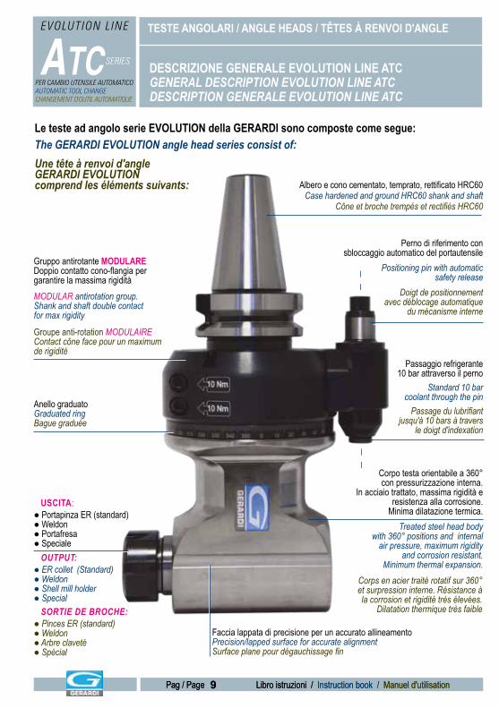
Albero e cono cementato, temprato, rettificato HRC60Case hardened and ground HRC60 shank and shaft
Cône et broche trempés et rectifiés HRC60
Gruppo antirotante MODULAREDoppio contatto cono-flangia pergarantire la massima rigidità
Perno di riferimento consbloccaggio automatico del portautensile
Passaggio refrigerante10 bar attraverso il perno
Corpo testa orientabile a 360°con pressurizzazione interna.
In acciaio trattato, massima rigidità e resistenza alla corrosione.
Minima dilatazione termica.
Anello graduatoGraduated ringBague graduée
OUTPUT:● ER collet (Standard)● Weldon● Shell mill holder● Special
Faccia lappata di precisione per un accurato allineamentoPrecision/lapped surface for accurate alignmentSurface plane pour dégauchissage fin
Treated steel head bodywith 360° positions and internal
air pressure, maximum rigidityand corrosion resistant.
Minimum thermal expansion.Corps en acier traité rotatif sur 360° et surpression interne. Résistance à la corrosion et rigidité très élevées.
Dilatation thermique très faible
USCITA:● Portapinza ER (standard)● Weldon● Portafresa● Speciale
SORTIE DE BROCHE:● Pinces ER (standard)● Weldon● Arbre claveté● Spécial
Standard 10 barcoolant through the pin
Passage du lubrifiant jusqu'à 10 bars à travers
le doigt d'indexation
Positioning pin with automatic safety release
Doigt de positionnement avec déblocage automatique
du mécanisme interneMODULAR antirotation group.Shank and shaft double contactfor max rigidity
Groupe anti-rotation MODULAIREContact cône face pour un maximum de rigidité
Le teste ad angolo serie EVOLUTION della GERARDI sono composte come segue:The GERARDI EVOLUTION angle head series consist of:Une tête à renvoi d'angle GERARDI EVOLUTION comprend les éléments suivants:
10
TESTE ANGOLARI / ANGLE HEADS / TÊTES À RENVOI D'ANGLE
Libro istruzioni / Instruction book / Manuel d'utilisation
ATC SERIES
EVOLUTION L INE
Pag / Page
PER CAMBIO UTENSILE AUTOMATICOAUTOMATIC TOOL CHANGECHANGEMENT D'OUTIL AUTOMATIQUE
1 - Bloccare la testa in morsa serrandola esclusivamente dal cono (Non serrare mai il corpo testa fra le ganasce. Rischio rottura) E' consigliato usare ganasce lisce per non rovinare il cono.2 - Allentare con chiave dinamometrica la vite di fissaggio del cono. Fare attenzione! La testa non è bloccata in morsa e quindi potrebbe cadere.
PROCEDURE PER CAMBIO CONO / TESTAOPERATIONS FOR ANGULAR HEAD SHANK EXCHANGEOPERATIONS POUR CHANGER LE CÔNE DE LA TÊTE
1 - Block the angle head with a vise clamping it exclusively from the shank (never clamp the angle head body between the jaws because of highest breaking risk). It is suggested the use of smooth jaws in order to avoid any damage.2 - Loosen with a torque wrench the shank clamping screw. Attention! The angle head is not clamped by the jaws so it might fall down.
4 - Eseguire il montaggio, ad incastro, fra la testa ed il nuovo gruppo cono.5 - Serrare la vite di bloccaggio del cono con una chiave dinamometrica tarata a 110 Nm di coppia.6 - Premere il perno di sgancio ed eseguire con un comparatore la verifica di concentricità tra l'asse del cono e l'asse centrale della testa angolare tramite la rotazione manuale del cono.
3 - Rimuovere i pezzi smontati3 - Remove the disassembled components3 - Séparez le cône et le corps
4 - Assemble by interlocking the angle head body and the new shank group.5 - Tighten the shank clamping screw with a torque wrench set at 110 Nm.6 - Push the release pin and with a clock gauge check the concentricity between the shank axis and the angle head central axis through the shank manual rotation.
Fase / Stage / Phase A
Fase / Stage / Phase B
Fase / Stage / Phase C
1 - Serrez le cône de la tête dans les mors d'un étau. (Ne serrez jamais le corps de la tête dans un étau au risque de la détériorer) Nous vous suggérons d'utiliser des mors lisses.2 - Dévissez la vis de serrage avec une clé dynamométrique. Attention! Le corps de la tête n'est plus maintenu et risque de tomber.
4 - Montez le corps sur le nouveau cône.5 - Serrez la vis de montage à un couple de 110Nm.6 - Appuyez sur le doigt de positionnement pour libérer la rotation de la tête et vérifiez la concentricité du cône au comparateur.
GanasciaJaw / Mors
GanasciaJaw / Mors
GanasciaJaw / Mors
GanasciaJaw / Mors
GanasciaJaw / Mors
GanasciaJaw / Mors
11
TESTE ANGOLARI / ANGLE HEADS / TÊTES À RENVOI D'ANGLE
Libro istruzioni / Instruction book / Manuel d'utilisation
ATC SERIES
EVOLUTION L INE
Pag / Page 11 Libro istruzioni / Instruction book / Manuel d'utilisationPag / Page
PER CAMBIO UTENSILE AUTOMATICOAUTOMATIC TOOL CHANGECHANGEMENT D'OUTIL AUTOMATIQUE
■ Le nostre teste ad angolo sono state concepite e costruite per effettuare lavorazioni di foratura, lamatura, maschiatura e fresatura.Le caratteristiche di funzionamento previste sono quelle riportate nelle pagg. 17,18,19 “Caratteristiche tecniche”
UTILIZZO DELLA TESTAANGLE HEADS USETETE UTILISATION
■ Our angle heads have been designed and built to carry out drilling, spotfacing, tapping and milling operations.The envisaged operating specifications are those shown in pages 17,18,19 "Technical Specifications”
■ Nos têtes à renvoi d'angle sont destinées aux opérations de perçage, pointage, taraudage, fraisage.Les possibilités techniques sont indiquées dans les pages 17,18,19 " Spécifications techniques "
■ Le nostre teste ad angolo non possono eseguire quelle lavorazioni meccaniche i cui parametri eccedono le caratteristiche tecniche della testa ad angolo stessa.
■ Our angle heads cannot perform mechanical operations whose parameters exceed the technical specifications of the angle head itself.
■ Nos têtes à renvoi d'angle ne peuvent pas réaliser de travaux avec des spécifications dépassant celles de la tête à renvoi d'angle
Ogni uso diverso da quelli previsti è da considerarsi non autorizzato. La GERARDI SPA non si assume nessuna responsabilità riguardo a danni a persone, cose od alla testa ad angolo stessa derivanti da un uso improprio.
All uses other than those intended shall be deemed unauthorised. GERARDI SPA cannot accept any liabiliy for injury to persons or damage to things or tothe angle head caused by improper machine use.
Tout usage autre que ceux indiqués est prohibé.GERARDI SPA n'acceptera aucune responsabilité sur des dégâts ou des blessures en cas d'usage inapproprié de la tête à renvoi d'angle.
USO PREVISTOINTENDED USEUTILISATION RECOMMANDEE
USO NON PREVISTOFORBIDDEN USEUTILISATION PROSCRITE
12
TESTE ANGOLARI / ANGLE HEADS / TÊTES À RENVOI D'ANGLE
Libro istruzioni / Instruction book / Manuel d'utilisation
ATC SERIES
EVOLUTION L INE
Pag / Page
PER CAMBIO UTENSILE AUTOMATICOAUTOMATIC TOOL CHANGECHANGEMENT D'OUTIL AUTOMATIQUE
NORME DI SICUREZZASAFETY NORMSNORMES DE SECURITE
ATTENZIONE! Seguire scrupolosamente le norme qui riassunte. GERARDI SPA si esime da qualsiasi responsabilità riguardo il non rispetto delle indicazioni.■ Non utilizzare la testa per qualsiasi uso diverso da quelli consentiti.■ Non fermare la testa tramite i mandrini o l’utensile.
IMPORTANT ! Suivez scrupuleusement les instructions indiquées dans ce manuel. GERARDI SPA n'acceptera aucune responsabilité sur les dégâts ou des blessures si vous n'avez pas respecté ces dernières.■ N'utilisez pas la tête à renvoi d'angle pour autre chose que ce qui est indiqué dans ce manuel. ■ Ne stoppez pas la tête par l'intermédiaire de l'outil ou de la broche.
IMPORTANT! Carefully follow the instructions indicated in this manual.GERARDI SPA cannot accept any liability for failure to comply with these instructions.■ Never use the head for purposes other than those indicated.■ Never stop the head by means of the spindle or tool.
Durante la lavorazione utilizzate i mezzi personali di protezione. Si raccomanda di effettuare ogni tipo di lavorazione rispettando la legislazione vigente in materia di sicurezza sul posto di lavoro.
Pendant l'usinage, portez toujours des équipements de sécurité. Toutes les opérations d'usinage doivent répondre aux règles et lois en vigueur dans votre pays.
During machining, always use means of personal protection. All machining operations must be performed in compliance with the safety regulations in force at the place of work.
■ Non pulire, lubrificare o effettaure manutenzioni durante il moto.■ Never clean, lubricate or ser vice the head while this is running.■ Ne nettoyez pas, ne lubrifiez pas la tête à renvoi d'angle pendant qu'elle tourne !
ATTENZIONE! per utilizzare il cambio utensile automatico verificate sempre che il peso e le dimensio-ni della testa siano compatibili con il vostro centro di lavoro. IMPORTANT! In order to use the angle head on an automatic tool change machine check always that the weight and the dimensions of the angular head are compatible with your machining centre.IMPORTANT! Pour utiliser la tête à renvoi d'angle avec un changeur d'outils automatique, vérifiez toujours que les dimensions et poids de la tête sont compatibles avec les capacités du changeur.
13
TESTE ANGOLARI / ANGLE HEADS / TÊTES À RENVOI D'ANGLE
Libro istruzioni / Instruction book / Manuel d'utilisation
ATC SERIES
EVOLUTION L INE
Pag / Page 13 Libro istruzioni / Instruction book / Manuel d'utilisationPag / Page
PER CAMBIO UTENSILE AUTOMATICOAUTOMATIC TOOL CHANGECHANGEMENT D'OUTIL AUTOMATIQUE
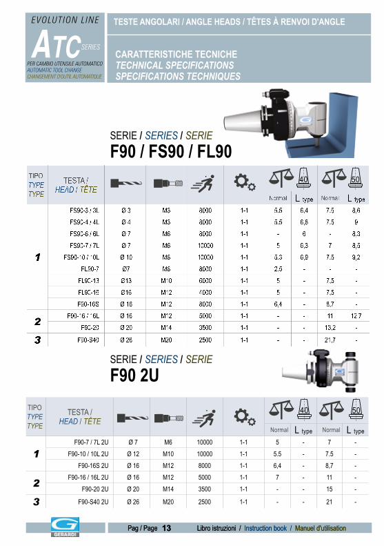
CARATTERISTICHE TECNICHETECHNICAL SPECIFICATIONSSPECIFICATIONS TECHNIQUES
TIPO TYPETYPE
TESTA / HEAD / TÊTE
Normal L type Normal L type
1
FS90-3 / 3L Ø 3 M3 8000 1-1 5.5 6,4 7.5 8,6FS90-4 / 4L Ø 4 M3 8000 1-1 5.5 6,8 7.5 9FS90-6 / 6L Ø 7 M6 8000 1-1 - 6 - 8,3FS90-7 / 7L Ø 7 M6 10000 1-1 5 6,3 7 8,5
FS90-10 / 10L Ø 10 M8 10000 1-1 5.3 6,9 7.5 9,2FL90-7 Ø7 M8 8000 1-1 2,5 - - -
FL90-13 Ø13 M10 6000 1-1 5 - 7,5 -FL90-16 Ø16 M12 4000 1-1 5 - 7,5 -F90-16S Ø 16 M12 8000 1-1 6,4 - 8,7 -
2F90-16 / 16L Ø 16 M12 5000 1-1 - - 11 12,7
F90-20 Ø 20 M14 3500 1-1 - - 13,2 -
3 F90-S40 Ø 26 M20 2500 1-1 - - 21,7 -
40 50
SERIE / SERIES / SERIEF90 2U
TIPO TYPETYPE
TESTA / HEAD / TÊTE
Normal L type Normal L type
1F90-7 / 7L 2U Ø 7 M6 10000 1-1 5 - 7 -
F90-10 / 10L 2U Ø 12 M10 10000 1-1 5.5 - 7.5 -F90-16S 2U Ø 16 M12 8000 1-1 6,4 - 8,7 -
2F90-16 / 16L 2U Ø 16 M12 5000 1-1 7 - 11 -
F90-20 2U Ø 20 M14 3500 1-1 - - 15 -
3 F90-S40 2U Ø 26 M20 2500 1-1 - - 21 -
40 50
SERIE / SERIES / SERIEF90 / FS90 / FL90
AX LOAD
10BAR
TORQUE
WEIGHT
DRILL
TAP
70 BAR
SPEED
AX LOAD
10BAR
TORQUE
WEIGHT
DRILL
TAP
70 BAR
SPEED
AX LOAD
10BAR
TORQUE
WEIGHT
DRILL
TAP
70 BAR
SPEED
AX LOAD
10BAR
TORQUE
WEIGHT
DRILL
TAP
70 BAR
SPEED
AX LOAD
10BAR
TORQUE
WEIGHT
DRILL
TAP
70 BAR
SPEED
AX LOAD
10BAR
TORQUE
WEIGHT
DRILL
TAP
70 BAR
SPEED
AX LOAD
10BAR
TORQUE
WEIGHT
DRILL
TAP
70 BAR
SPEED
AX LOAD
10BAR
TORQUE
WEIGHT
DRILL
TAP
70 BAR
SPEED
AX LOAD
10BAR
TORQUE
WEIGHT
DRILL
TAP
70 BAR
SPEED
AX LOAD
10BAR
TORQUE
WEIGHT
DRILL
TAP
70 BAR
SPEED
AX LOAD
10BAR
TORQUE
WEIGHT
DRILL
TAP
70 BAR
SPEED
AX LOAD
10BAR
TORQUE
WEIGHT
DRILL
TAP
70 BAR
SPEED
14
TESTE ANGOLARI / ANGLE HEADS / TÊTES À RENVOI D'ANGLE
Libro istruzioni / Instruction book / Manuel d'utilisation
ATC SERIES
EVOLUTION L INE
Pag / Page
PER CAMBIO UTENSILE AUTOMATICOAUTOMATIC TOOL CHANGECHANGEMENT D'OUTIL AUTOMATIQUE
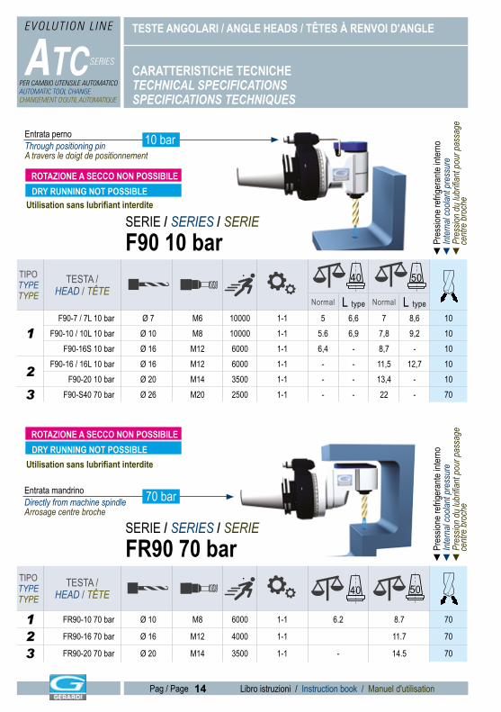
TIPO TYPETYPE
TESTA / HEAD / TÊTE
Normal L type Normal L type
1F90-7 / 7L 10 bar Ø 7 M6 10000 1-1 5 6,6 7 8,6 10
F90-10 / 10L 10 bar Ø 10 M8 10000 1-1 5.6 6,9 7,8 9,2 10F90-16S 10 bar Ø 16 M12 6000 1-1 6,4 - 8,7 - 10
2F90-16 / 16L 10 bar Ø 16 M12 6000 1-1 - - 11,5 12,7 10
F90-20 10 bar Ø 20 M14 3500 1-1 - - 13,4 - 10
3 F90-S40 70 bar Ø 26 M20 2500 1-1 - - 22 - 70
CARATTERISTICHE TECNICHETECHNICAL SPECIFICATIONSSPECIFICATIONS TECHNIQUES
40 50
TIPO TYPETYPE
TESTA / HEAD / TÊTE
1 FR90-10 70 bar Ø 10 M8 6000 1-1 6.2 8.7 70
2 FR90-16 70 bar Ø 16 M12 4000 1-1 11.7 70
3 FR90-20 70 bar Ø 20 M14 3500 1-1 - 14.5 70
40 50
SERIE / SERIES / SERIEF90 10 bar ◄
Pre
ssion
e refr
igera
nte in
terno
◄ In
tern
al co
olant
pre
ssur
e◄
Pre
ssion
du
lubrifi
ant p
our p
assa
ge
cen
tre b
roch
e
SERIE / SERIES / SERIEFR90 70 bar ◄
Pre
ssion
e refr
igera
nte in
terno
◄ In
tern
al co
olant
pre
ssur
e◄
Pre
ssion
du
lubrifi
ant p
our p
assa
ge
cen
tre b
roch
e
Entrata pernoThrough positioning pinA travers le doigt de positionnement
Entrata mandrinoDirectly from machine spindleArrosage centre broche
70 bar
DRY RUNNING NOT POSSIBLE
10 bar
Utilisation sans lubrifiant interdite
Utilisation sans lubrifiant interdite
ROTAZIONE A SECCO NON POSSIBILE
DRY RUNNING NOT POSSIBLEROTAZIONE A SECCO NON POSSIBILE
AX LOAD
10BAR
TORQUE
WEIGHT
DRILL
TAP
70 BAR
SPEED
AX LOAD
10BAR
TORQUE
WEIGHT
DRILL
TAP
70 BAR
SPEED
AX LOAD
10BAR
TORQUE
WEIGHT
DRILL
TAP
70 BAR
SPEED
AX LOAD
10BAR
TORQUE
WEIGHT
DRILL
TAP
70 BAR
SPEED
AX LOAD
10BAR
TORQUE
WEIGHT
DRILL
TAP
70 BAR
SPEED
AX LOAD
10BAR
TORQUE
WEIGHT
DRILL
TAP
70 BAR
SPEED
AX LOAD
10BAR
TORQUE
WEIGHT
DRILL
TAP
70 BAR
SPEED
AX LOAD
10BAR
TORQUE
WEIGHT
DRILL
TAP
70 BAR
SPEED
AX LOAD
10BAR
TORQUE
WEIGHT
DRILL
TAP
70 BAR
SPEED
AX LOAD
10BAR
TORQUE
WEIGHT
DRILL
TAP
70 BAR
SPEED
AX LOAD
10BAR
TORQUE
WEIGHT
DRILL
TAP
70 BAR
SPEED
AX LOAD
10BAR
TORQUE
WEIGHT
DRILL
TAP
70 BAR
SPEED
15
TESTE ANGOLARI / ANGLE HEADS / TÊTES À RENVOI D'ANGLE
Libro istruzioni / Instruction book / Manuel d'utilisation
ATC SERIES
EVOLUTION L INE
Pag / Page 15 Libro istruzioni / Instruction book / Manuel d'utilisationPag / Page
PER CAMBIO UTENSILE AUTOMATICOAUTOMATIC TOOL CHANGECHANGEMENT D'OUTIL AUTOMATIQUE
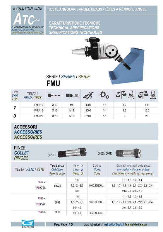
TIPO TYPETYPE
TESTA / HEAD / TÊTE
1FMU-10 Ø 10 M8 4000 1-1 6,3 8,8
FMU-16 Ø 16 M12 3000 1-1 8,2 10.5
3 FMU-20 Ø 20 M16 2500 1-1 - 22
40 50
SERIE / SERIES / SERIEFMU
CARATTERISTICHE TECNICHETECHNICAL SPECIFICATIONSSPECIFICATIONS TECHNIQUES
TESTA / HEAD / TÊTETipo di pinzaCollet type
Type de pince
Pinza ØCollet ØPince Ø
CodiceCodeCode
Diametri intermedi delle pinzeIntermediary diameter collets
Diamètres intermédiaires des pinces
FS90-3
FS90-3L 6023E
1,0
9.60.23E00/...
1,1 - 1,2 - 1,3 - 1,4
1,5 - 2 - 2,5 1,6 - 1,7 - 1,8 -1,9 - 2,1 - 2,2 - 2,3 - 2,4
3,0 2,6 - 2,7 - 2,8 - 2,9
FS90-4
FS90-4L 600E
1,0
9.60.0E000/...
1,1 - 1,2 - 1,3 - 1,4
1,5 - 2 - 2,5 1,6 - 1,7 - 1,8 -1,9 - 2,1 - 2,2 - 2,3 - 2,4
3,0 - 4,0 2,6 - 2,7 - 2,8 - 2,9FS90-6 601E 1,0 - 6,0 9.60.1E000/... -
ACCESSORIACCESSORIESACCESSOIRES
PINZECOLLETPINCES
6023E 600E / 601E
AX LOAD
10BAR
TORQUE
WEIGHT
DRILL
TAP
70 BAR
SPEED AX LOAD
10BAR
TORQUE
WEIGHT
DRILL
TAP
70 BAR
SPEED
AX LOAD
10BAR
TORQUE
WEIGHT
DRILL
TAP
70 BAR
SPEEDAX LOAD
10BAR
TORQUE
WEIGHT
DRILL
TAP
70 BAR
SPEED
AX LOAD
10BAR
TORQUE
WEIGHT
DRILL
TAP
70 BAR
SPEED
AX LOAD
10BAR
TORQUE
WEIGHT
DRILL
TAP
70 BAR
SPEED
16
TESTE ANGOLARI / ANGLE HEADS / TÊTES À RENVOI D'ANGLE
Libro istruzioni / Instruction book / Manuel d'utilisation
ATC SERIES
EVOLUTION L INE
Pag / Page
PER CAMBIO UTENSILE AUTOMATICOAUTOMATIC TOOL CHANGECHANGEMENT D'OUTIL AUTOMATIQUE
ACCESSORIACCESSORIESACCESSOIRES
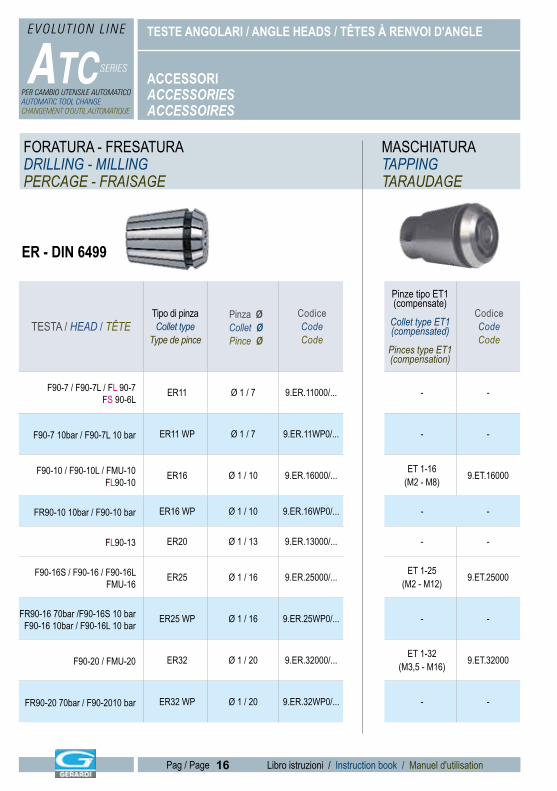
FORATURA - FRESATURADRILLING - MILLINGPERCAGE - FRAISAGE
MASCHIATURATAPPINGTARAUDAGE
ER - DIN 6499
TESTA / HEAD / TÊTETipo di pinzaCollet type
Type de pince
Pinza ØCollet ØPince Ø
CodiceCodeCode
F90-7 / F90-7L / FL 90-7FS 90-6L
ER11 Ø 1 / 7 9.ER.11000/...
F90-7 10bar / F90-7L 10 bar ER11 WP Ø 1 / 7 9.ER.11WP0/...
F90-10 / F90-10L / FMU-10FL90-10
ER16 Ø 1 / 10 9.ER.16000/...
FR90-10 10bar / F90-10 bar ER16 WP Ø 1 / 10 9.ER.16WP0/...
FL90-13 ER20 Ø 1 / 13 9.ER.13000/...
F90-16S / F90-16 / F90-16LFMU-16
ER25 Ø 1 / 16 9.ER.25000/...
FR90-16 70bar /F90-16S 10 barF90-16 10bar / F90-16L 10 bar
ER25 WP Ø 1 / 16 9.ER.25WP0/...
F90-20 / FMU-20 ER32 Ø 1 / 20 9.ER.32000/...
FR90-20 70bar / F90-2010 bar ER32 WP Ø 1 / 20 9.ER.32WP0/...
Pinze tipo ET1(compensate)
Collet type ET1(compensated)
Pinces type ET1(compensation)
CodiceCodeCode
- -
- -
ET 1-16(M2 - M8) 9.ET.16000
- -
- -
ET 1-25(M2 - M12) 9.ET.25000
- -
ET 1-32(M3,5 - M16) 9.ET.32000
- -
17
TESTE ANGOLARI / ANGLE HEADS / TÊTES À RENVOI D'ANGLE
Libro istruzioni / Instruction book / Manuel d'utilisation
ATC SERIES
EVOLUTION L INE
Pag / Page 17 Libro istruzioni / Instruction book / Manuel d'utilisationPag / Page
PER CAMBIO UTENSILE AUTOMATICOAUTOMATIC TOOL CHANGECHANGEMENT D'OUTIL AUTOMATIQUE
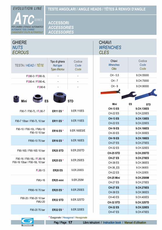
GHIERENUTSECROUS
CHIAVIWRENCHESCLES
ChiaviWrenches
Clés
CodiceCodeCode
CH - 5,5 9.CH.55000
CH - 7 9.CH.70000
CH - 9 9.CH.90000
CH-13 ES 9.CH.130ESCH-22 ES 9.CH.220ES
CH-13 ES 9.CH.130ESCH-22 ES 9.CH.220ES
CH-19 ES 9.CH.190ESCH-30 ES 9.CH.300ES
CH-19 ES 9.CH.190ESCH-27 ES 9.CH.270ESCH-32 ES 9.CH.320ES
CH-25 STD 9.CH.25STDCH-27 ES 9.CH.270ESCH-38 ES 9.CH.380ESCH-36_ES 9.CH.360ES
CH-22 ES 9.CH.220ES
CH-25 Mini 9.CH.2500MCH-27 ES 9.CH.270ES
CH-27 ES 9.CH.270ESCH-38 ES 9.CH.380ESCH-40 ES 9.CH.400ES
CH-32 STD 9.CH.32STDCH-32 ES 9.CH.320ESCH-47 ES 9.CH.470ES
TESTA / HEAD / TÊTETipo di ghiera
Nut typeType d'écrou
CodiceCodeCode
FS90-3 / FS90-3L - -
FS90-4 / FS90-4L - -
FS90-6 - -
F90-7 / F90-7L / FL90-7 ER11 ES * 9.ER.110ES
F90-7 10bar / F90-7L 10 bar ER11 ES * 9.ER.110ES
F90-10 / F90-10L / FMU-10F90-10 10 bar ER16 ES * 9.ER.160ES/E
FR90-10 70 bar ER16 ES * 9.ER.160ES
F90-16S / F90-16S 10 bar ER25 STD 9.ER.25STD
F90-16 / F90-16L / FL90-16F90-16 10bar / F90-16L 10 bar ER25 ES * 9.ER.250ES
FL90-13 ER20 ES 9.ER.200ES
FMU-16 ER25 mini 9.ER.250M
FR90-16 70 bar ER25 ES * 9.ER.250ES
F90-20 / F90-20 10 barFMU-20 ER32 STD 9.ER.32STD
F90-20 70 bar ER32 ES * 9.ER.320ES
Mini ES STD
* Esagonale / Hexagonal / Hexagonale
ACCESSORIACCESSORIESACCESSOIRES
STDESMini
18
TESTE ANGOLARI / ANGLE HEADS / TÊTES À RENVOI D'ANGLE
Libro istruzioni / Instruction book / Manuel d'utilisation
ATC SERIES
EVOLUTION L INE
Pag / Page
PER CAMBIO UTENSILE AUTOMATICOAUTOMATIC TOOL CHANGECHANGEMENT D'OUTIL AUTOMATIQUE
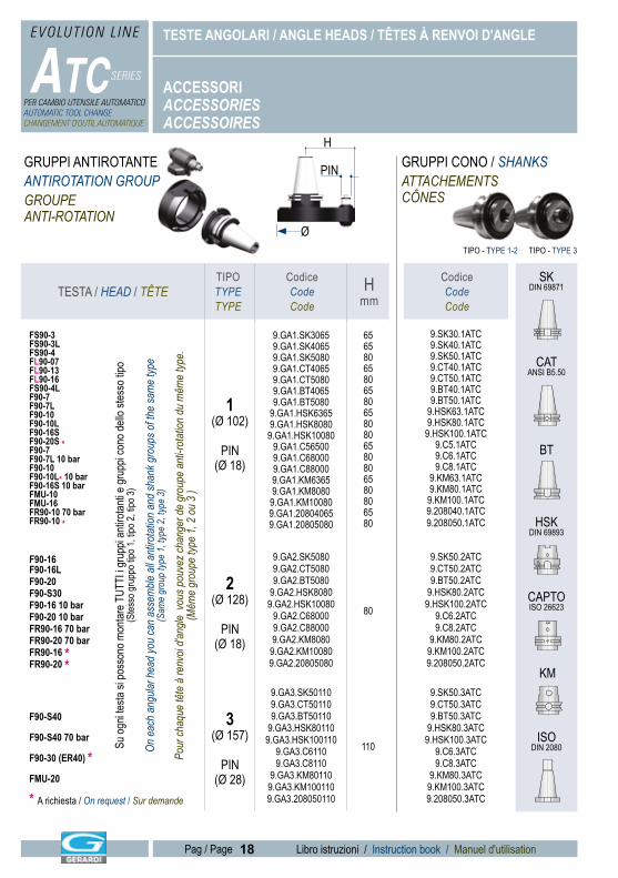
TESTA / HEAD / TÊTETIPOTYPETYPE
CodiceCodeCode
Hmm
FS90-3FS90-3LFS90-4FL90-07FL90-13FL90-16FS90-4LF90-7F90-7LF90-10F90-10LF90-16SF90-20S *F90-7F90-7L 10 barF90-10F90-10L* 10 bar F90-16S 10 barFMU-10FMU-16FR90-10 70 barFR90-10 *
1(Ø 102)
PIN(Ø 18)
9.GA1.SK30659.GA1.SK40659.GA1.SK50809.GA1.CT40659.GA1.CT50809.GA1.BT40659.GA1.BT5080
9.GA1.HSK63659.GA1.HSK80809.GA1.HSK10080
9.GA1.C565009.GA1.C680009.GA1.C880009.GA1.KM63659.GA1.KM80809.GA1.KM100809.GA1.208040659.GA1.20805080
656580658065806580806580806580806580
F90-16F90-16LF90-20F90-S30F90-16 10 barF90-20 10 barFR90-16 70 barFR90-20 70 barFR90-16 *FR90-20 *
2(Ø 128)
PIN(Ø 18)
9.GA2.SK50809.GA2.CT50809.GA2.BT5080
9.GA2.HSK80809.GA2.HSK10080
9.GA2.C680009.GA2.C880009.GA2.KM80809.GA2.KM100809.GA2.20805080
80
F90-S40
F90-S40 70 bar
F90-30 (ER40) *FMU-20
3(Ø 157)
PIN(Ø 28)
9.GA3.SK501109.GA3.CT501109.GA3.BT50110
9.GA3.HSK801109.GA3.HSK100110
9.GA3.C61109.GA3.C8110
9.GA3.KM801109.GA3.KM1001109.GA3.208050110
110
ACCESSORIACCESSORIESACCESSOIRES
SKDIN 69871
CATANSI B5.50
BT
HSKDIN 69893
CAPTOISO 26623
KM
ISODIN 2080
GRUPPI ANTIROTANTEANTIROTATION GROUPGROUPEANTI-ROTATION
GRUPPI CONO / SHANKSATTACHEMENTSCÔNES
Ø
H
PIN
CodiceCodeCode
9.SK30.1ATC9.SK40.1ATC9.SK50.1ATC9.CT40.1ATC9.CT50.1ATC9.BT40.1ATC9.BT50.1ATC
9.HSK63.1ATC9.HSK80.1ATC
9.HSK100.1ATC9.C5.1ATC9.C6.1ATC9.C8.1ATC
9.KM63.1ATC9.KM80.1ATC
9.KM100.1ATC9.208040.1ATC9.208050.1ATC
9.SK50.2ATC9.CT50.2ATC9.BT50.2ATC
9.HSK80.2ATC9.HSK100.2ATC
9.C6.2ATC9.C8.2ATC
9.KM80.2ATC9.KM100.2ATC9.208050.2ATC
9.SK50.3ATC9.CT50.3ATC9.BT50.3ATC
9.HSK80.3ATC9.HSK100.3ATC
9.C6.3ATC9.C8.3ATC
9.KM80.3ATC9.KM100.3ATC9.208050.3ATC* A richiesta / On request / Sur demande
Su og
ni tes
ta si
poss
ono m
ontar
e TUT
TI i g
rupp
i anti
rotan
ti e gr
uppi
cono
dello
stes
so tip
o(S
tesso
grup
po tip
o 1, ti
po 2,
tipo 3
)
On e
ach
angu
lar h
ead
you
can
asse
mble
all a
ntiro
tatio
n an
d sh
ank g
roup
s of t
he sa
me
type
(Sam
e gr
oup
type
1, ty
pe 2
, typ
e 3)
Pour
chaq
ue tê
te à
renv
oi d'a
ngle
vous
pou
vez c
hang
er d
e gr
oupe
ant
i-rot
ation
du
mêm
e typ
e.(M
ême
grou
pe ty
pe 1
, 2 o
u 3
)
TIPO - TYPE 1-2 TIPO - TYPE 3
19
TESTE ANGOLARI / ANGLE HEADS / TÊTES À RENVOI D'ANGLE
Libro istruzioni / Instruction book / Manuel d'utilisation
ATC SERIES
EVOLUTION L INE
Pag / Page 19 Libro istruzioni / Instruction book / Manuel d'utilisationPag / Page
PER CAMBIO UTENSILE AUTOMATICOAUTOMATIC TOOL CHANGECHANGEMENT D'OUTIL AUTOMATIQUE
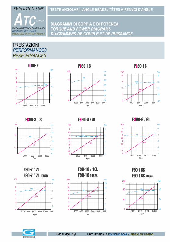
DIAGRAMMI DI COPPIA E DI POTENZATORQUE AND POWER DIAGRAMSDIAGRAMMES DE COUPLE ET DE PUISSANCE
FL90-13FL90-7 FL90-16Nm
Nm
KW
KW
Rpm
7
5
3
7
5
6
4
3
2
1
0800040002000 6000
Nm
Nm
KW
KW
Rpm
14
16
18
20
22
12
15
10
0400020001000 5000 60003000
Rpm
KW
KW
Nm
Nm
2820
15
10
5
01000 30002000 4000
26
24
22
20
Rpm
Nm
Nm
KW
KW
32
1,5
1
0,5
02000 60004000 8000
2,5
2
1,5
1
0,5
0
FS90-3 / 3L FS90-4 / 4L FS90-6 / 6L
Rpm
Nm
Nm
KW
KW
5
4
3
2
43,5
2,5
1
3
1,52
0,50
2000 60004000 80001
Rpm
Nm
Nm
KW
KW
5
4
3
2
43,5
2,5
1
3
1,52
0,50
2000 60004000 80001
F90-10 / 10LF90-10 10BAR
F90-16SF90-16S 10BAR
F90-7 / 7L F90-7 / 7L 10BAR
Nm
Nm
KW
KW
Rpm
8
6
4
2
7
5
6
4
3
2
1
0800040002000 10000 120006000
Nm
Nm
KW
KW
Rpm
15
13
11
9
7
5
14
10
12
8
6
4
2
0800040002000 10000 120006000
20
10
02000 60004000 8000
28
24
20
Nm
Nm
KW
KW
Rpm
PRESTAZIONIPERFORMANCESPERFORMANCES
20
TESTE ANGOLARI / ANGLE HEADS / TÊTES À RENVOI D'ANGLE
Libro istruzioni / Instruction book / Manuel d'utilisation
ATC SERIES
EVOLUTION L INE
Pag / Page
PER CAMBIO UTENSILE AUTOMATICOAUTOMATIC TOOL CHANGECHANGEMENT D'OUTIL AUTOMATIQUE
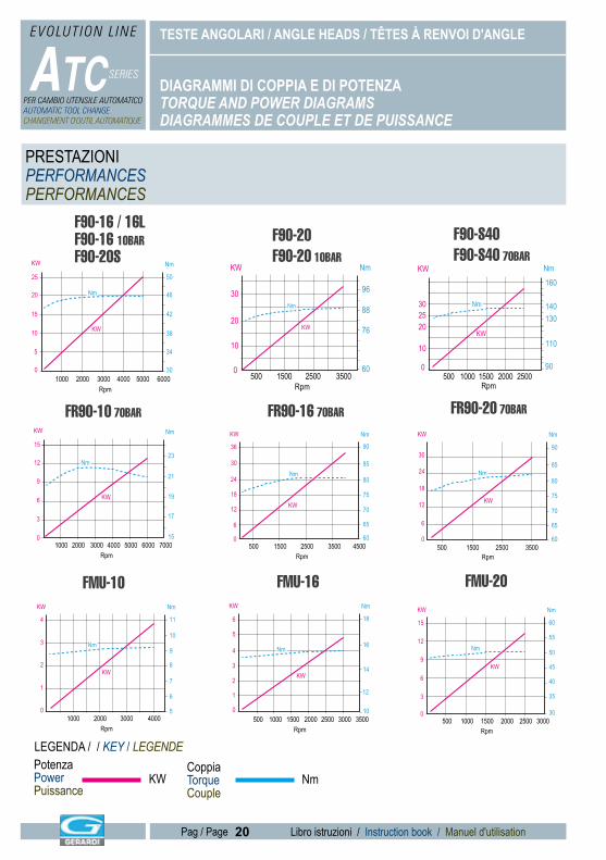
DIAGRAMMI DI COPPIA E DI POTENZATORQUE AND POWER DIAGRAMSDIAGRAMMES DE COUPLE ET DE PUISSANCE
LEGENDA / / KEY / LEGENDEPotenzaPowerPuissance
CoppiaTorqueCouple
KW Nm
F90-20F90-20 10BAR
F90-16 / 16LF90-16 10BARF90-20S Nm
Nm
KW
KW
Rpm
34
38
42
46
50
30
25
15
20
10
5
0400020001000 5000 60003000
Nm
Nm
KW
KW
Rpm
20
30
10
0500 25001500 3500
76
88
96
60
FR90-16 70BAR FR90-10 70BAR
F90-S40F90-S40 70BAR
Nm
Nm
KW
KW
Rpm
160
140
110
130
90
2530
20
10
020001000500 25001500
Nm
Nm
KW
KW
Rpm
15
12
9
6
3
01000 500030002000 60004000 7000
19
23
21
17
15
KW
KW
Rpm
9036
12
18
24
30
6
0500 25001500 3500 4500
65
70
75
80
85
60
Nm
Nm
FMU-16
FR90-20 70BAR
FMU-10
Rpm
KW
KW
Nm
Nm
90
12
18
24
30
6
0500 25001500 3500
65
70
75
80
85
60
Rpm
KW
KW
Nm
Nm
114
3
2
1
01000 30002000 4000
10
9
8
7
6
5
Rpm
KW
KW
Nm
Nm
12
14
16
18
10
6
3
4
5
2
1
0250015001000500 3000 35002000
FMU-20
Rpm
KW
KW
Nm
Nm
60
12
15
9
6
3
0500 15001000 2000 2500 3000
50
55
45
40
35
30
PRESTAZIONIPERFORMANCESPERFORMANCES
TESTE ANGOLARI / ANGLE HEADS / TÊTES À RENVOI D'ANGLE
ATC SERIES
EVOLUTION L INE
PER CAMBIO UTENSILE AUTOMATICOAUTOMATIC TOOL CHANGECHANGEMENT D'OUTIL AUTOMATIQUE
ISTRUZIONI OPERATIVE - OPERATIVE INSTRUCTION - MODE D'EMPLOI
21 Libro istruzioni / Instruction book / Manuel d'utilisationPag / Page 21 Libro istruzioni / Instruction book / Manuel d'utilisationPag / Page
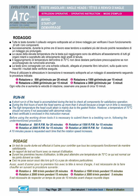
■ Tutte le teste durante il collaudo vengono sottoposte ad un breve rodaggio per verificare il buon funzionamento di tutti i loro componenti. ■ Successivamente, durante le prime ore di lavoro esse tendono a scaldarsi più del dovuto poichè necessitano di un rodaggio più prolungato. ■ Le cause della elevata temperatura che la testa può raggiungere sono da attribuire all'assestamento di tutti gli organi rotanti e soprattutto allo strisciamento degli anelli di tenuta. ■ Il raggiungimento di temperature dell'ordine di 70°C non deve destare particolare preoccupazione se non accompagnato da rumorosità anomala. ■ Le teste sono consegnate con una scheda collaudo, allegata al presente libro istruzioni, sulla quale sono trascritti i risultati delle verifiche eseguite.Prima di utilizzare le attrezzature in lavorazione è necessario sottoporle ad un rodaggio di assestamento seguendo la procedura indicata: Ê Rotazione a 500 giri/minuto per 20 minuti Ë Rotazione a 1500 giri/minuto per 15 minuti Ì Rotazione a 2000 giri/minuto per 15 minuti Í Rotazione a 3000 giri/minuto per 5 minutiOgni volta che si aumenta la velocità di rotazione, osservare una pausa di circa 10 minuti.
■ A short run-in of the head is accomplished during the test to check all components for satisfactory operation.■ During the first hours of work the head warms up more than it should because a longer run-in time is necessary.■ The high temperature the head could attain is mainly due to the gasket friction. However, a temperature of 70°C should not worry if not associated with abnormal noise.■ A test certificate is enclosed in this instruction manual.Before using the working driven tools it is necessary to submit them to a bedding run-in, following the undermentioned procedure: Ê Rotation at 500 R.P.M. for 20 minutes Ë Rotation at 1500 R.P.M. for 15 minutes Ì Rotation at 2000 R.P.M. for 15 minutes Í Rotation at 3000 R.P.M. for 5 minutesA 10 minutes pause is requested each time that the rotation speed increases.
■ Un test de courte durée est effectué à l'usine pour contrôler que tous les composants fonctionnent de manière satisfaisante.■ Un rapport de test est fourni avec ce manuel d'utilisation.■ Durant les premières heures d'utilisation, la tête peut atteindre une température de 70°C ce qui est normal car les joints doivent se roder.■ Ceci ne pose aucun souci dès lors qu'il n'y a pas de vibrations particulières.Aussi, avant d'usiner pour la première fois avec la tête à renvoi d'angle, il est nécessaire de la faire chauffer en suivant la procédure suivante : Ê Rotation à 500 tr/min pendant 20 minutes Ë Rotation à 1500 tr/min pendant 15 minutes Ì Rotation à 2000 tr/min pendant 15 minutes Í Rotation à 3000 tr/min pendant 5 minutesIl est nécessaire de respecter un temps de pose de 10 minutes avant chaque nouvelle étape.
RODAGGIO
RUN-IN
RODAGE
AVVIOSTART-UP DEMARRAGE
TESTE ANGOLARI / ANGLE HEADS / TÊTES À RENVOI D'ANGLE
ATC SERIES
EVOLUTION L INE
PER CAMBIO UTENSILE AUTOMATICOAUTOMATIC TOOL CHANGECHANGEMENT D'OUTIL AUTOMATIQUE
ISTRUZIONI OPERATIVE - OPERATIVE INSTRUCTION - MODE D'EMPLOI
22 Libro istruzioni / Instruction book / Manuel d'utilisationPag / Page
TIPO CONO
-Tassello di fermo o perno speciale-Special retaining block or positioning pin-Stop block ou doigt de positionnement spécial.
SHANK TYPETIPO CONOSHANK TYPE
TIPO CONOSHANK TYPECÔNE TYPE CÔNE TYPE CÔNE TYPE
ØE
ØC
ØA
ØD
ØB
GX
XX
ØDØC
ØAØB ØB
H H H
ØA
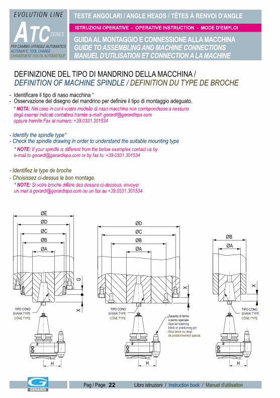
GUIDA AL MONTAGGIO E CONNESSIONE ALLA MACCHINAGUIDE TO ASSEMBLING AND MACHINE CONNECTIONSMANUEL D'UTILISATION ET CONNECTION A LA MACHINE
- Identificare il tipo di naso macchina *- Osservazione del disegno del mandrino per definire il tipo di montaggio adeguato.
- Identify the spindle type*- Check the spindle drawing in order to understand the suitable mounting type
- Identifiez le type de broche- Choisissez ci-dessus le bon montage.
DEFINIZIONE DEL TIPO DI MANDRINO DELLA MACCHINA / DEFINITION OF MACHINE SPINDLE / DEFINITION DU TYPE DE BROCHE
* NOTA: Nel caso in cui il vostro modello di naso macchina non corrispondesse a nessuno degli esempi indicati contatteci tramite e-mail: [email protected] oppure tramite Fax al numero: +39.0331.301534
* NOTE: If your spindle is different from the below examples contact us by e-mail to [email protected] or by fax to: +39.0331.301534
* NOTE: Si votre broche diffère des dessins ci-dessous, envoyer un mail à [email protected] ou un fax au +39.0331.301534
TESTE ANGOLARI / ANGLE HEADS / TÊTES À RENVOI D'ANGLE
ATC SERIES
EVOLUTION L INE
PER CAMBIO UTENSILE AUTOMATICOAUTOMATIC TOOL CHANGECHANGEMENT D'OUTIL AUTOMATIQUE
ISTRUZIONI OPERATIVE - OPERATIVE INSTRUCTION - MODE D'EMPLOI
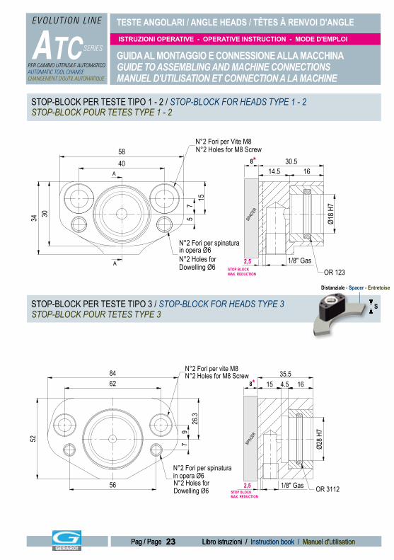
23 Libro istruzioni / Instruction book / Manuel d'utilisationPag / Page 23 Libro istruzioni / Instruction book / Manuel d'utilisationPag / Page
GUIDA AL MONTAGGIO E CONNESSIONE ALLA MACCHINAGUIDE TO ASSEMBLING AND MACHINE CONNECTIONSMANUEL D'UTILISATION ET CONNECTION A LA MACHINE
STOP BLOCK MAX. REDUCTION
2,5A
A
1/8" Gas
Ø18 H
7
1614.530.540
58
157
534 30
N°2 Fori per Vite M8N°2 Holes for M8 Screw
N°2 Fori per spinaturain opera Ø6N°2 Holes forDowelling Ø6 OR 123
8*
SPAC
ER
STOP BLOCK MAX. REDUCTION
2,5N°2 Holes forDowelling Ø6
8*
SPAC
ER
62
52
26.3
97
84
1/8" Gas
Ø28 H
7
1635.5
15 4.5
56
N°2 Fori per spinaturain opera Ø6
N°2 Fori per vite M8N°2 Holes for M8 Screw
OR 3112
STOP-BLOCK PER TESTE TIPO 1 - 2 / STOP-BLOCK FOR HEADS TYPE 1 - 2STOP-BLOCK POUR TETES TYPE 1 - 2
STOP-BLOCK PER TESTE TIPO 3 / STOP-BLOCK FOR HEADS TYPE 3STOP-BLOCK POUR TETES TYPE 3
Distanziale - Spacer - Entretoise
S
TESTE ANGOLARI / ANGLE HEADS / TÊTES À RENVOI D'ANGLE
ATC SERIES
EVOLUTION L INE
PER CAMBIO UTENSILE AUTOMATICOAUTOMATIC TOOL CHANGECHANGEMENT D'OUTIL AUTOMATIQUE
ISTRUZIONI OPERATIVE - OPERATIVE INSTRUCTION - MODE D'EMPLOI
24 Libro istruzioni / Instruction book / Manuel d'utilisationPag / Page
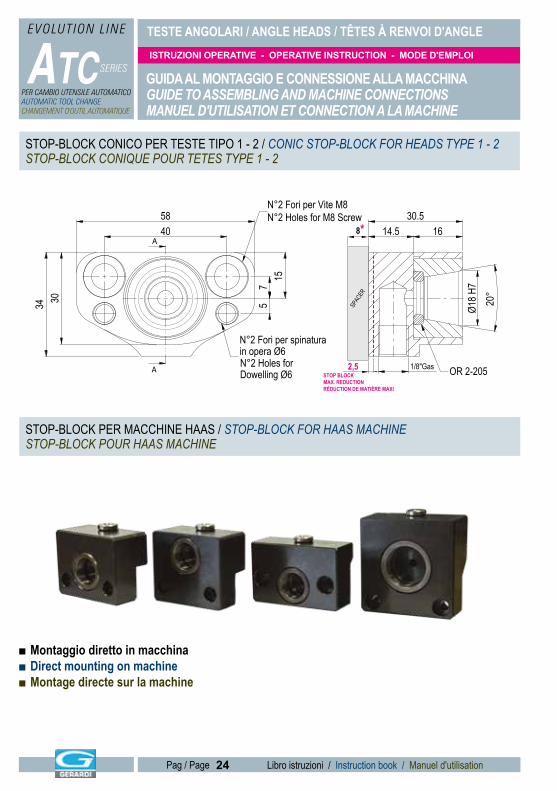
GUIDA AL MONTAGGIO E CONNESSIONE ALLA MACCHINAGUIDE TO ASSEMBLING AND MACHINE CONNECTIONSMANUEL D'UTILISATION ET CONNECTION A LA MACHINE
■ Montaggio diretto in macchina■ Direct mounting on machine■ Montage directe sur la machine
2,5STOP BLOCK MAX. REDUCTIONRÉDUCTION DE MATIÈRE MAXI
N°2 Holes forDowelling Ø6A
A4058
3034
157
5
1/8"Gas
Ø18 H
70°2
1630.5
14.5
N°2 Fori per Vite M8N°2 Holes for M8 Screw
N°2 Fori per spinaturain opera Ø6
OR 2-205
8*
SPAC
ER
STOP-BLOCK CONICO PER TESTE TIPO 1 - 2 / CONIC STOP-BLOCK FOR HEADS TYPE 1 - 2STOP-BLOCK CONIQUE POUR TETES TYPE 1 - 2
STOP-BLOCK PER MACCHINE HAAS / STOP-BLOCK FOR HAAS MACHINE STOP-BLOCK POUR HAAS MACHINE
TESTE ANGOLARI / ANGLE HEADS / TÊTES À RENVOI D'ANGLE
ATC SERIES
EVOLUTION L INE
PER CAMBIO UTENSILE AUTOMATICOAUTOMATIC TOOL CHANGECHANGEMENT D'OUTIL AUTOMATIQUE
ISTRUZIONI OPERATIVE - OPERATIVE INSTRUCTION - MODE D'EMPLOI
25 Libro istruzioni / Instruction book / Manuel d'utilisationPag / Page 25 Libro istruzioni / Instruction book / Manuel d'utilisationPag / Page
GUIDA AL MONTAGGIO E CONNESSIONE ALLA MACCHINAGUIDE TO ASSEMBLING AND MACHINE CONNECTIONSMANUEL D'UTILISATION ET CONNECTION A LA MACHINE
A
A
115
26.5
42.5 Ø18 H
7
16
26
10
15
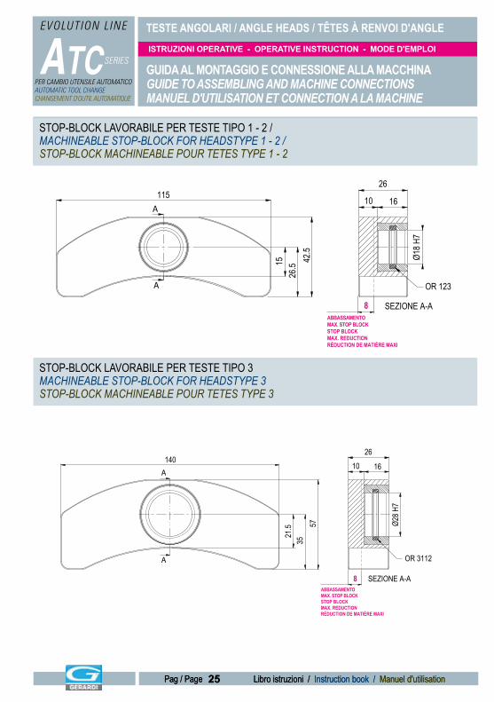
SEZIONE A-A
OR 123
8ABBASSAMENTO MAX. STOP BLOCKSTOP BLOCK MAX. REDUCTIONRÉDUCTION DE MATIÈRE MAXI
A
A
2610 16
140
3557
21.5 Ø2
8 H7
SEZIONE A-A
OR 3112
8ABBASSAMENTO MAX. STOP BLOCKSTOP BLOCK MAX. REDUCTIONRÉDUCTION DE MATIÈRE MAXI
STOP-BLOCK LAVORABILE PER TESTE TIPO 1 - 2 / MACHINEABLE STOP-BLOCK FOR HEADSTYPE 1 - 2 / STOP-BLOCK MACHINEABLE POUR TETES TYPE 1 - 2
STOP-BLOCK LAVORABILE PER TESTE TIPO 3 MACHINEABLE STOP-BLOCK FOR HEADSTYPE 3 STOP-BLOCK MACHINEABLE POUR TETES TYPE 3
TESTE ANGOLARI / ANGLE HEADS / TÊTES À RENVOI D'ANGLE
ATC SERIES
EVOLUTION L INE
PER CAMBIO UTENSILE AUTOMATICOAUTOMATIC TOOL CHANGECHANGEMENT D'OUTIL AUTOMATIQUE
ISTRUZIONI OPERATIVE - OPERATIVE INSTRUCTION - MODE D'EMPLOI
26 Libro istruzioni / Instruction book / Manuel d'utilisationPag / Page
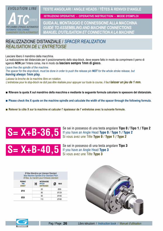
REALIZZAZIONE DISTANZIALE / SPACER REALIZATIONREALISATION DE L' ENTRETOISE
Lasciare libero il mandrino della macchina.La realizzazione del distanziale per il posizionamento dello stop-block, deve essere fatto in modo da comprimere il perno di sgancio NON per l’intera corsa, ma in modo da lasciare sempre 1mm di gioco.Leave free the spindle of the machine. The spacer for the stop-block, must be done in order to push the release pin NOT for the whole stroke release, butleaving always 1mm play.
GUIDA AL MONTAGGIO E CONNESSIONE ALLA MACCHINAGUIDE TO ASSEMBLING AND MACHINE CONNECTIONSMANUEL D'UTILISATION ET CONNECTION A LA MACHINE
Laissez la broche de la machine libre en rotation. L'entretoise pour le stop-block ne doit pas être réalisée pour appuyer sur toute la course, il faut laisser un jeu de 1 mm.
Ø Max Mandrino per Interassi StandardMax Machine Spindle Ø for Standard PitchØ Max. du mandrin pour Entraxes standard
PERNO PIN
DOIGT HINTERASSE PITCHENTRAXES Ø MAX
Ø18 65 Ø9980 Ø129
Ø28 80 Ø106110 Ø166
■ Rilevare la quota X sul mandrino della macchina e mediante la seguente formula calcolare lo spessore del distanziale.
■ Please check the X quote on the machine spindle and calculate the width of the spacer through the following formula.
■ Relever la côte X sur la machine et calculer l' épaisseur de l' entretoise avec la suivante formule.
S= X+B-36,5Se sei in possesso di una testa angolare Tipo 0 / Tipo 1 / Tipo 2 If you have an Angle Head Type 0 / Type 1 / Type 2Si vous avez une Tête Type 0 / Type 1 / Type 2
S= X+B-40,5Se sei in possesso di una testa angolare Tipo 3 If you have an Angle Head Type 3Si vous avez une Tête Type 3
TESTE ANGOLARI / ANGLE HEADS / TÊTES À RENVOI D'ANGLE
ATC SERIES
EVOLUTION L INE
PER CAMBIO UTENSILE AUTOMATICOAUTOMATIC TOOL CHANGECHANGEMENT D'OUTIL AUTOMATIQUE
ISTRUZIONI OPERATIVE - OPERATIVE INSTRUCTION - MODE D'EMPLOI
27 Libro istruzioni / Instruction book / Manuel d'utilisationPag / Page 27 Libro istruzioni / Instruction book / Manuel d'utilisationPag / Page
■ Realizzare un distanziale con uno spessore “S” che consenta di ottenere una corsa del perno di sgancio pari a 7,5mm (6mm per teste tipo 3). In caso di spessori inferiori a 8 mm è possibile richiedere un apposito stop-block con base lavorabile (Pag. 27) ■ Lo stop-block si deve adeguare al perno di posizionamento. ■ Distanziale e stop-block andranno posizionati in modo da non ostacolare il cambio utensile. È possibile abbassare il perno di posizionamento 13,5mm max.■ Prepare a spacer with dimension "S" which allows to get a stroke release of the release pin equal to 7,5mm (6mm for type 3). In case of widths of less than 8mm, a special stop block with machineable base can be ordered (Pag27) ■ The stop-block must adapt to the pin. ■ The spacer and the stop-block will be placed in order not to hinder the tool change. You can lower the pin of 13,5mm max.■ Préparez une entretoise avec une épaisseur "S" qui permet d'avoir une course de sortie de 7,5mm (7mm pourune tête type 3). Si les èpaisseurs sont moins de 8mm, vous pouvez commander un stop-block spècial avecbase machineable. ■ Le stop-block doit être adapté au doigt de positionnement. ■ L'entretoise et le stop-block sont placés de façon à ne pas gêner le changement d'outil. Vous pouvez raccourcir le doigt de positionnement de 13,5mm max.
GUIDA AL MONTAGGIO E CONNESSIONE ALLA MACCHINAGUIDE TO ASSEMBLING AND MACHINE CONNECTIONSMANUEL D'UTILISATION ET CONNECTION A LA MACHINE
XB 1
= =
ØMax(Tabella-Table)
H
Filo conoGauge LinePlan de jauge A*
S14
,5
TappoCap
*A21mm type 1-224,5mm type 3
Perno Standard PinDoigt Standard
1A*
S14
,515
1,5
Perno TipoPin type
26,3= Ø281-2
Perno TipoPin type 3
15= Ø18
Dettaglio pernoPin detail
Détail doigt
Perno di sgancioRelease pinDoigt de déblocage
■ Turn the shank of the head so that the drag keys of the spindle enter into their seats
■ Orientate il cono della testa in modo che le chiavette di trascinamento sul mandrino entrinonelle apposite sedi
■ Tournez le cône de la tête jusqu'à ce que les rainures de l'attachement coïncident avec les tenons d'entraînement de la broche de la machine
Step 1 / Phase 1
Step 2 / Phase 2 ■Stringere i due grani dopo la fasatura del cono■Tighten the 2 set screws after shank timing ■ Serrez les deux vis après avoir réglé la position du côneSe sei in possesso di una testa angolare Tipo 0 / Tipo 1 / Tipo 2
If you have an Angle Head Type 0 / Type 1 / Type 2Si vous avez une Tête Type 0 / Type 1 / Type 2
Se sei in possesso di una testa angolare Tipo 3 If you have an Angle Head Type 3Si vous avez une Tête Type 3
TESTE ANGOLARI / ANGLE HEADS / TÊTES À RENVOI D'ANGLE
ATC SERIES
EVOLUTION L INE
PER CAMBIO UTENSILE AUTOMATICOAUTOMATIC TOOL CHANGECHANGEMENT D'OUTIL AUTOMATIQUE
ISTRUZIONI OPERATIVE - OPERATIVE INSTRUCTION - MODE D'EMPLOI
28 Libro istruzioni / Instruction book / Manuel d'utilisationPag / Page
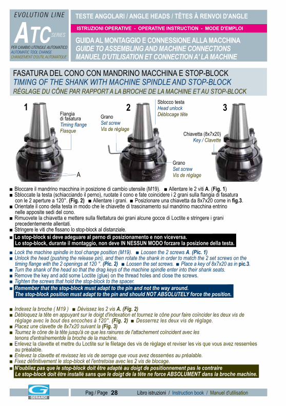
■ Bloccare il mandrino macchina in posizione di cambio utensile (M19). ■ Allentare le 2 viti A. (Fig. 1)■ Sbloccate la testa (schiacciando il perno), ruotate il cono e fate coincidere i 2 grani sulla flangia di fasatura con le 2 aperture a 120°. (Fig. 2) ■ Allentare i grani. ■ Posizionare una chiavetta da 8x7x20 come in fig.3.■ Orientate il cono della testa in modo che le chiavette di trascinamento sul mandrino macchina entrino nelle apposite sedi del cono.■ Rimuovete la chiavetta e mettere sulla filettatura dei grani alcune gocce di Loctite e stringere i grani precedentemente allentati.■ Stringere le viti che fissano lo stop-block al distanziale. ■ Lo stop-block si deve adeguare al perno di posizionamento e non viceversa. Lo stop-block, durante il montaggio, non deve IN NESSUN MODO forzare la posizione della testa.■ Lock the machine spindle in tool change position (M19). ■ Loosen the 2 screws A. (Pic. 1)■ Unlock the head (pushing the release pin), and then rotate the shank in order to match the 2 set screws on the timing flange with the 2 openings at 120 °. (Pic. 2) ■ Loosen the set screws. ■ Place a key of 8x7x20 as in pic.3.■ Turn the shank of the head so that the drag keys of the machine spindle enter into their shank seats.■ Remove the key and add some Loctite (glue) on the thread holes and close the screws.■ Tighten the screws that hold the stop-block to the spacer. ■ Remember that the stop-block must adapt to the pin and not the way around. The stop-block position must adapt to the pin and should NOT ABSOLUTELY force the position.
■ Indexez la broche ( M19 ) ■ Dévissez les 2 vis A. (Fig. 2) ■ Débloquez la tête en appuyant sur le doigt d'indexation et tournez le cône pour faire coïncider les deux vis de réglage avec le bout des encoches à 120°. (Fig. 2) ■ Desserrez les deux vis de réglage.■ Placez une clavette de 8x7x20 suivant la (Fig. 3)■ Tournez le cône de la tête jusqu'à ce que les rainures de l'attachement coïncident avec les tenons d'entraînementde la broche de la machine.■ Enlevez la clavette et mettre du Loctite sur le filetage des vis de règlage et reviser les vis que vous avez resserrèes au prèalable.■ Enlevez la clavette et revissez les vis de serrage que vous avez desserrées au préalable.■ Fixez définitivement le stop-block et l'entretoise avec les 2 vis de blocage. ■ N'oubliez pas que le stop-block doit être adapté au doigt de positionnement pas le contraire Le stop-block doit être installé sans que le doigt de la tête ne force ABSOLUMENT dans la broche machine.
GUIDA AL MONTAGGIO E CONNESSIONE ALLA MACCHINAGUIDE TO ASSEMBLING AND MACHINE CONNECTIONSMANUEL D'UTILISATION ET CONNECTION A' LA MACHINE
GranoSet screwVis de réglage
Flangia di fasaturaTiming flangeFlasque Chiavetta (8x7x20)
Key / Clavette
Sblocco testaHead unlockDéblocage tête
21
A
3
GranoSet screwVis de réglage
FASATURA DEL CONO CON MANDRINO MACCHINA E STOP-BLOCKTIMING OF THE SHANK WITH MACHINE SPINDLE AND STOP-BLOCKRÉGLAGE DU CÔNE PAR RAPPORT A LA BROCHE DE LA MACHINE ET AU STOP-BLOCK
TESTE ANGOLARI / ANGLE HEADS / TÊTES À RENVOI D'ANGLE
ATC SERIES
EVOLUTION L INE
PER CAMBIO UTENSILE AUTOMATICOAUTOMATIC TOOL CHANGECHANGEMENT D'OUTIL AUTOMATIQUE
ISTRUZIONI OPERATIVE - OPERATIVE INSTRUCTION - MODE D'EMPLOI
29 Libro istruzioni / Instruction book / Manuel d'utilisationPag / Page 29 Libro istruzioni / Instruction book / Manuel d'utilisationPag / Page
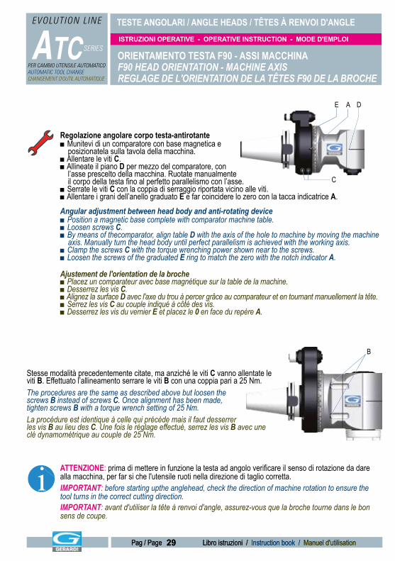
Regolazione angolare corpo testa-antirotante■ Munitevi di un comparatore con base magnetica e posizionatela sulla tavola della macchina.■ Allentare le viti C. ■ Allineate il piano D per mezzo del comparatore, con l’asse prescelto della macchina. Ruotate manualmente il corpo della testa fino al perfetto parallelismo con l’asse.■ Serrate le viti C con la coppia di serraggio riportata vicino alle viti. ■ Allentare i grani dell’anello graduato E e far coincidere lo zero con la tacca indicatrice A.Angular adjustment between head body and anti-rotating device ■ Position a magnetic base complete with comparator machine table.■ Loosen screws C. ■ By means of thecomparator, align table D with the axis of the hole to machine by moving the machine axis. Manually turn the head body until perfect parallelism is achieved with the working axis. ■ Clamp the screws C with the torque wrenching power shown near to the screws.■ Loosen the screws of the graduated E ring to match the zero with the notch indicator A.
Ajustement de l'orientation de la broche■ Placez un comparateur avec base magnétique sur la table de la machine.■ Desserrez les vis C.■ Alignez la surface D avec l'axe du trou à percer grâce au comparateur et en tournant manuellement la tête.■ Serrez les vis C au couple indiqué à côté des vis.■ Desserrez les vis du vernier E et placez le 0 en face du repère A.
ATTENZIONE: prima di mettere in funzione la testa ad angolo verificare il senso di rotazione da dare alla macchina, per far si che l'utensile ruoti nella direzione di taglio corretta.IMPORTANT: before starting upthe anglehead, check the direction of machine rotation to ensure the tool turns in the correct cutting direction.IMPORTANT: avant d'utiliser la tête à renvoi d'angle, assurez-vous que la broche tourne dans le bon sens de coupe.
B
Stesse modalità precedentemente citate, ma anziché le viti C vanno allentate le viti B. Effettuato l’allineamento serrare le viti B con una coppia pari a 25 Nm.The procedures are the same as described above but loosen thescrews B instead of screws C. Once alignment has been made,tighten screws B with a torque wrench setting of 25 Nm.La procédure est identique à celle qui précède mais il faut desserrer les vis B au lieu des C. Une fois le réglage effectué, serrez les vis B avec une clé dynamométrique au couple de 25 Nm.
i
ORIENTAMENTO TESTA F90 - ASSI MACCHINAF90 HEAD ORIENTATION - MACHINE AXISREGLAGE DE L'ORIENTATION DE LA TÊTES F90 DE LA BROCHE
C
A DE
TESTE ANGOLARI / ANGLE HEADS / TÊTES À RENVOI D'ANGLE
ATC SERIES
EVOLUTION L INE
PER CAMBIO UTENSILE AUTOMATICOAUTOMATIC TOOL CHANGECHANGEMENT D'OUTIL AUTOMATIQUE
ISTRUZIONI OPERATIVE - OPERATIVE INSTRUCTION - MODE D'EMPLOI
30 Libro istruzioni / Instruction book / Manuel d'utilisationPag / Page
ORIENTAMENTO TESTA FMU - ASSI MACCHINAFMU HEAD ORIENTATION - MACHINE AXISREGLAGE DE L'ORIENTATION DE LA TÊTES FMU DE LA BROCHE
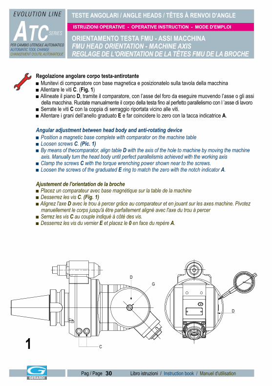
Regolazione angolare corpo testa-antirotante■ Munitevi di comparatore con base magnetica e posizionatelo sulla tavola della macchina■ Allentare le viti C. (Fig. 1)■ Allineate il piano D, tramite il comparatore, con l’asse del foro da eseguire muovendo l’asse o gli assi della macchina. Ruotate manualmente il corpo della testa fino al perfetto parallelismo con l ’asse di lavoro■ Serrate le viti C con la coppia di serraggio riportata vicino alle viti. ■ Allentare i grani dell’anello graduato E e far coincidere lo zero con la tacca indicatrice A.
Angular adjustment between head body and anti-rotating device ■ Position a magnetic base complete with comparator on the machine table■ Loosen screws C. (Pic. 1)■ By means of thecomparator, align table D with the axis of the hole to machine by moving the machine axis. Manually turn the head body until perfect parallelismis achieved with the working axis■ Clamp the screws C with the torque wrenching power shown near to the screws.■ Loosen the screws of the graduated E ring to match the zero with the notch indicator A.
Ajustement de l'orientation de la broche■ Placez un comparateur avec base magnétique sur la table de la machine ■ Desserrez les vis C. (Fig. 1)■ Alignez l'axe D avec le trou à percer grâce au comparateur et en jouant sur les axes machine. Pivotez manuellement le corps jusqu'à être parfaitement aligné avec l'axe du trou à percer■ Serrez les vis C au couple indiqué à côté des vis.■ Desserrez les vis du vernier E et placez le 0 en face du repère A.
D
GD
C1
TESTE ANGOLARI / ANGLE HEADS / TÊTES À RENVOI D'ANGLE
ATC SERIES
EVOLUTION L INE
PER CAMBIO UTENSILE AUTOMATICOAUTOMATIC TOOL CHANGECHANGEMENT D'OUTIL AUTOMATIQUE
ISTRUZIONI OPERATIVE - OPERATIVE INSTRUCTION - MODE D'EMPLOI
31 Libro istruzioni / Instruction book / Manuel d'utilisationPag / Page 31 Libro istruzioni / Instruction book / Manuel d'utilisationPag / Page
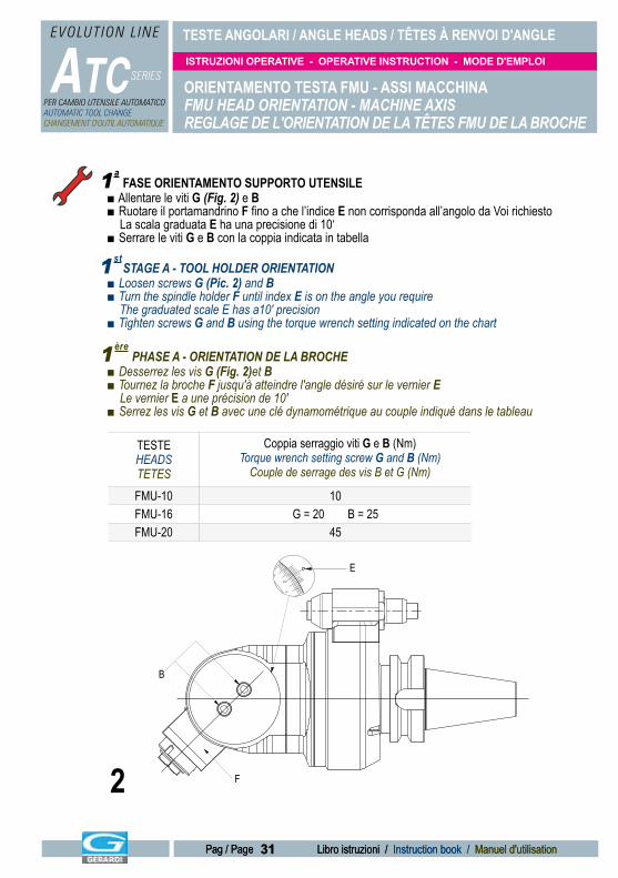
TESTEHEADSTETES
Coppia serraggio viti G e B (Nm)Torque wrench setting screw G and B (Nm)
Couple de serrage des vis B et G (Nm)
FMU-10 10FMU-16 G = 20 B = 25FMU-20 45
ORIENTAMENTO TESTA FMU - ASSI MACCHINAFMU HEAD ORIENTATION - MACHINE AXISREGLAGE DE L'ORIENTATION DE LA TÊTES FMU DE LA BROCHE
FASE ORIENTAMENTO SUPPORTO UTENSILE■ Allentare le viti G (Fig. 2) e B■ Ruotare il portamandrino F fino a che l’indice E non corrisponda all’angolo da Voi richiesto La scala graduata E ha una precisione di 10‘■ Serrare le viti G e B con la coppia indicata in tabella
STAGE A - TOOL HOLDER ORIENTATION■ Loosen screws G (Pic. 2) and B■ Turn the spindle holder F until index E is on the angle you require The graduated scale E has a10' precision■ Tighten screws G and B using the torque wrench setting indicated on the chart
PHASE A - ORIENTATION DE LA BROCHE■ Desserrez les vis G (Fig. 2)et B■ Tournez la broche F jusqu'à atteindre l'angle désiré sur le vernier E Le vernier E a une précision de 10'■ Serrez les vis G et B avec une clé dynamométrique au couple indiqué dans le tableau
F
B
E
1a
1st
1ère
2
TESTE ANGOLARI / ANGLE HEADS / TÊTES À RENVOI D'ANGLE
ATC SERIES
EVOLUTION L INE
PER CAMBIO UTENSILE AUTOMATICOAUTOMATIC TOOL CHANGECHANGEMENT D'OUTIL AUTOMATIQUE
ISTRUZIONI OPERATIVE - OPERATIVE INSTRUCTION - MODE D'EMPLOI
32 Libro istruzioni / Instruction book / Manuel d'utilisationPag / Page
ORIENTAMENTO TESTA FMU- ASSI MACCHINAFMU HEAD ORIENTATION - MACHINE AXISREGLAGE DE L'ORIENTATION DE LA TÊTES FMU DE LA BROCHE
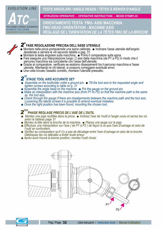
FASE REGOLAZIONE PRECISA DELL'ASSE UTENSILE■ Montare nella pinza portautensile una spina calibrata. ■ Inclinare l'asse utensile dell'angolo desiderato e serrare le viti secondo tabella a pag. 31■ Montare la testa angolare sulla macchina. ■ Porre il comparatore sulla spina.■ Fare eseguire una interpolazione lungo i 2 assi della macchina (da P1 a P2) in modo che il percorso macchina sia coincidente con l'asse dell'utensile.■ Grazie al comparatore, verificare se esistono disassamenti tra il percorso macchina e l'asse utensile. Allentando le viti laterali, si possono correggere eventuali errori.■ Una volta trovato l'assetto corretto, montare l'utensile prescelto.
STAGE TOOL AXIS ACCURATE SET■ Assemble on the toolholder collet a ground pin. ■ Tilt the tool axis to the requested angle and tighten screws according to table on p. 31■ Assemble the angle head on the machine. ■ Put the gauge on the ground pin.■ Make an interpolation with the machine axis (from P1 to P2) so that the machine path is the same as the tool axis.■ Check through the gauge if there are misalignments between the machine path and the tool axis. Loosening the lateral screws it is possible to amend eventual mistakes.■ Once the right position has been found, mounting the chosen tool.
PHASE REGLAGE PRECIS DE L'AXE DE L'OUTIL■ Montez une pige rectifiée dans la pince. ■ Inclinez l'axe de l'outil à l'angle voulu et serrez les vis selon le tableau page 31■ Montez la tête dans la broche de la machine. ■ Placez une jauge sur la pige.■ Effectuez une interpolation sur l'axe ( de P1 à P2 ) de façon à ce que l'axe d'usinage et celui de l'outil se confondent.■ Vérifiez au comparateur qu'il n'y a pas de décalage entre l'axe d'usinage et celui de la broche. Débloquez les vis latérales a éviter toute erreur.■ Après avoir trouvé la bonne position, montez l'outil choisi.
P1P2
2ème
2nd
2a
TESTE ANGOLARI / ANGLE HEADS / TÊTES À RENVOI D'ANGLE
ATC SERIES
EVOLUTION L INE
PER CAMBIO UTENSILE AUTOMATICOAUTOMATIC TOOL CHANGECHANGEMENT D'OUTIL AUTOMATIQUE
ISTRUZIONI OPERATIVE - OPERATIVE INSTRUCTION - MODE D'EMPLOI
33 Libro istruzioni / Instruction book / Manuel d'utilisationPag / Page 33 Libro istruzioni / Instruction book / Manuel d'utilisationPag / Page
TU
ØG
Q
S
P
ØG
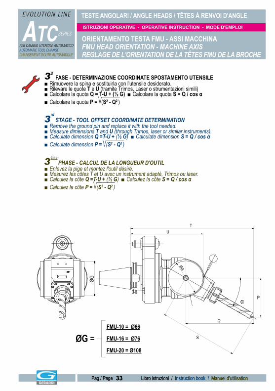
ORIENTAMENTO TESTA FMU - ASSI MACCHINAFMU HEAD ORIENTATION - MACHINE AXISREGLAGE DE L'ORIENTATION DE LA TÊTES FMU DE LA BROCHE
FASE - DETERMINAZIONE COORDINATE SPOSTAMENTO UTENSILE■ Rimuovere la spina e sostituirla con l'utensile desiderato.■ Rilevare le quote T e U (tramite Trimos, Laser o strumentazioni simili)■ Calcolare la quota Q = T-U + (½ G) ■ Calcolare la quota S = Q / cos α■ Calcolare la quota P = (S2 - Q2 )
STAGE - TOOL OFFSET COORDINATE DETERMINATION■ Remove the ground pin and replace it with the tool needed.■ Measure dimensions T and U (through Trimos, laser or similar instruments).■ Calculate dimension Q =T-U + (½ G) ■ Calculate dimension S = Q / cos α■ Calculate dimension P = (S2 - Q2 )
α
PHASE - CALCUL DE LA LONGUEUR D'OUTIL■ Enlevez la pige et montez l'outil désiré.■ Mesurez les côtes T et U avec un instrument adapté, Trimos ou laser.■ Calculez la côte Q =T-U + (½ G) ■ Calculez la côte S = Q / cos α■ Calculez la côte P = (S2 - Q2 )
FMU-10 = Ø66
FMU-16 = Ø76
FMU-20 = Ø108
ØG =
3ème
3rd
3a
TESTE ANGOLARI / ANGLE HEADS / TÊTES À RENVOI D'ANGLE
ATC SERIES
EVOLUTION L INE
PER CAMBIO UTENSILE AUTOMATICOAUTOMATIC TOOL CHANGECHANGEMENT D'OUTIL AUTOMATIQUE
ISTRUZIONI OPERATIVE - OPERATIVE INSTRUCTION - MODE D'EMPLOI
34 Libro istruzioni / Instruction book / Manuel d'utilisationPag / Page
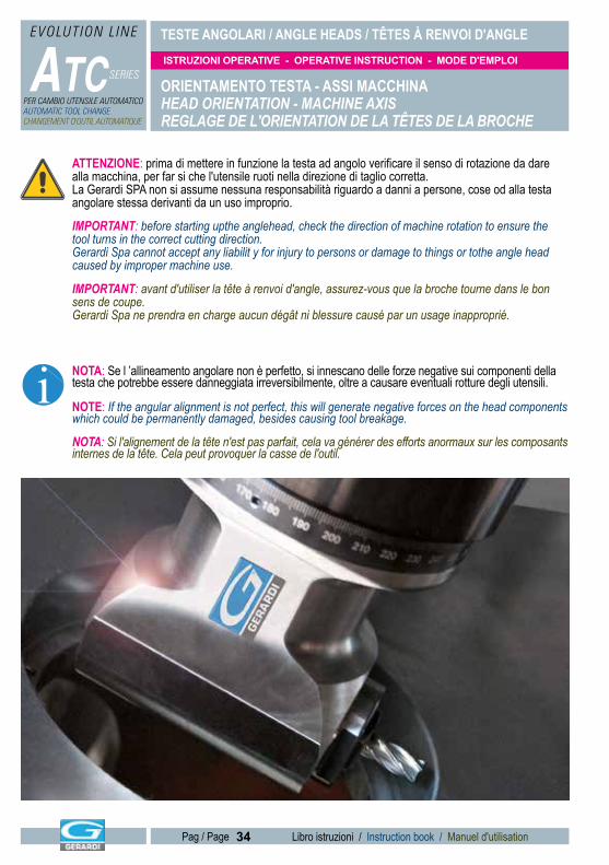
ATTENZIONE: prima di mettere in funzione la testa ad angolo verificare il senso di rotazione da dare alla macchina, per far si che l'utensile ruoti nella direzione di taglio corretta.La Gerardi SPA non si assume nessuna responsabilità riguardo a danni a persone, cose od alla testa angolare stessa derivanti da un uso improprio.
IMPORTANT: before starting upthe anglehead, check the direction of machine rotation to ensure the tool turns in the correct cutting direction.Gerardi Spa cannot accept any liabilit y for injury to persons or damage to things or tothe angle head caused by improper machine use.
IMPORTANT: avant d'utiliser la tête à renvoi d'angle, assurez-vous que la broche tourne dans le bon sens de coupe.Gerardi Spa ne prendra en charge aucun dégât ni blessure causé par un usage inapproprié.
i NOTA: Se l ’allineamento angolare non è perfetto, si innescano delle forze negative sui componenti della testa che potrebbe essere danneggiata irreversibilmente, oltre a causare eventuali rotture degli utensili.
NOTE: If the angular alignment is not perfect, this will generate negative forces on the head components which could be permanently damaged, besides causing tool breakage.
NOTA: Si l'alignement de la tête n'est pas parfait, cela va générer des efforts anormaux sur les composants internes de la tête. Cela peut provoquer la casse de l'outil.
ORIENTAMENTO TESTA - ASSI MACCHINAHEAD ORIENTATION - MACHINE AXISREGLAGE DE L'ORIENTATION DE LA TÊTES DE LA BROCHE
TESTE ANGOLARI / ANGLE HEADS / TÊTES À RENVOI D'ANGLE
ATC SERIES
EVOLUTION L INE
PER CAMBIO UTENSILE AUTOMATICOAUTOMATIC TOOL CHANGECHANGEMENT D'OUTIL AUTOMATIQUE
ISTRUZIONI OPERATIVE - OPERATIVE INSTRUCTION - MODE D'EMPLOI
35 Libro istruzioni / Instruction book / Manuel d'utilisationPag / Page 35 Libro istruzioni / Instruction book / Manuel d'utilisationPag / Page
REGOLAZIONI VARIEVARIOUS ADJUSTMENTSREGLAGES DIVERS
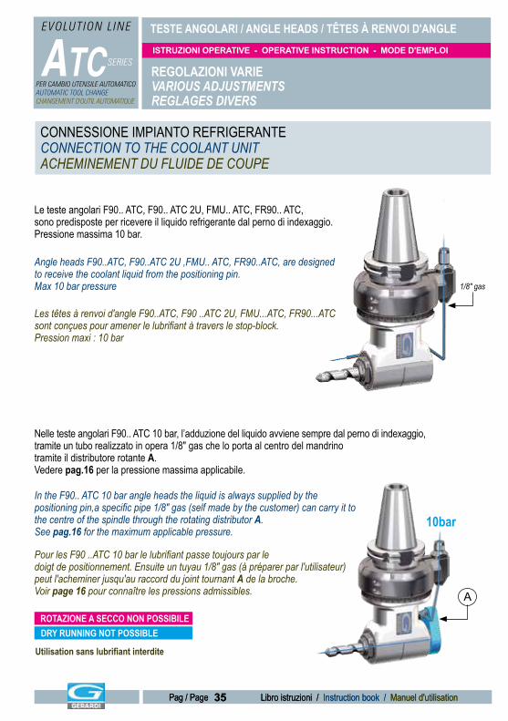
Le teste angolari F90.. ATC, F90.. ATC 2U, FMU.. ATC, FR90.. ATC, sono predisposte per ricevere il liquido refrigerante dal perno di indexaggio. Pressione massima 10 bar.
Angle heads F90..ATC, F90..ATC 2U ,FMU.. ATC, FR90..ATC, are designed to receive the coolant liquid from the positioning pin. Max 10 bar pressure
Nelle teste angolari F90.. ATC 10 bar, l’adduzione del liquido avviene sempre dal perno di indexaggio, tramite un tubo realizzato in opera 1/8" gas che lo porta al centro del mandrino tramite il distributore rotante A. Vedere pag.16 per la pressione massima applicabile.
In the F90.. ATC 10 bar angle heads the liquid is always supplied by the positioning pin,a specific pipe 1/8" gas (self made by the customer) can carry it to the centre of the spindle through the rotating distributor A. See pag.16 for the maximum applicable pressure.
Pour les F90 ..ATC 10 bar le lubrifiant passe toujours par le doigt de positionnement. Ensuite un tuyau 1/8" gas (à préparer par l'utilisateur) peut l'acheminer jusqu'au raccord du joint tournant A de la broche. Voir page 16 pour connaître les pressions admissibles.
Les têtes à renvoi d'angle F90..ATC, F90 ..ATC 2U, FMU...ATC, FR90...ATC sont conçues pour amener le lubrifiant à travers le stop-block. Pression maxi : 10 bar
1/8" gas
10bar
A
Utilisation sans lubrifiant interdite
DRY RUNNING NOT POSSIBLEROTAZIONE A SECCO NON POSSIBILE
CONNESSIONE IMPIANTO REFRIGERANTECONNECTION TO THE COOLANT UNITACHEMINEMENT DU FLUIDE DE COUPE
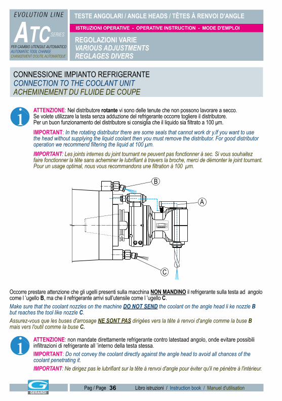
TESTE ANGOLARI / ANGLE HEADS / TÊTES À RENVOI D'ANGLE
ATC SERIES
EVOLUTION L INE
PER CAMBIO UTENSILE AUTOMATICOAUTOMATIC TOOL CHANGECHANGEMENT D'OUTIL AUTOMATIQUE
ISTRUZIONI OPERATIVE - OPERATIVE INSTRUCTION - MODE D'EMPLOI
36 Libro istruzioni / Instruction book / Manuel d'utilisationPag / Page
REGOLAZIONI VARIEVARIOUS ADJUSTMENTSREGLAGES DIVERS
i ATTENZIONE: Nel distributore rotante vi sono delle tenute che non possono lavorare a secco. Se volete utilizzare la testa senza adduzione del refrigerante occorre togliere il distributore. Per un buon funzionamento del distributore si consiglia che il liquido sia filtrato a 100 μm.IMPORTANT: In the rotating distributor there are some seals that cannot work dr y.If you want to use the head without supplying the liquid coolant then you must remove the distributor. For good distributor operation we recommend filtering the liquid at 100 μm.IMPORTANT: Les joints internes du joint tournant ne peuvent pas fonctionner à sec. Si vous souhaitez faire fonctionner la tête sans acheminer le lubrifiant à travers la broche, merci de démonter le joint tournant. Pour un usage optimal, nous vous recommandons une filtration à 100 μm.
i ATTENZIONE: non mandate direttamente refrigerante contro latestaad angolo, onde evitare possibili infiltrazioni di refrigerante all ’interno della testa stessa.IMPORTANT: Do not convey the coolant directly against the angle head to avoid all chances of the coolant penetrating it.IMPORTANT: Ne dirigez pas le lubrifiant sur la tête à renvoi d'angle pour éviter qu'il ne pénètre à l'intérieur.
Occorre prestare attenzione che gli ugelli presenti sulla macchina NON MANDINO il refrigerante sulla testa ad angolo come l ’ugello B, ma che il refrigerante arrivi sull’utensile come l ’ugello C.Make sure that the coolant nozzles on the machine DO NOT SEND the coolant on the angle head li ke nozzle B but reaches the tool like nozzle C.Assurez-vous que les buses d'arrosage NE SONT PAS dirigées vers la tête à renvoi d'angle comme la buse B mais vers l'outil comme la buse C.
A
B
C
CONNESSIONE IMPIANTO REFRIGERANTECONNECTION TO THE COOLANT UNITACHEMINEMENT DU FLUIDE DE COUPE
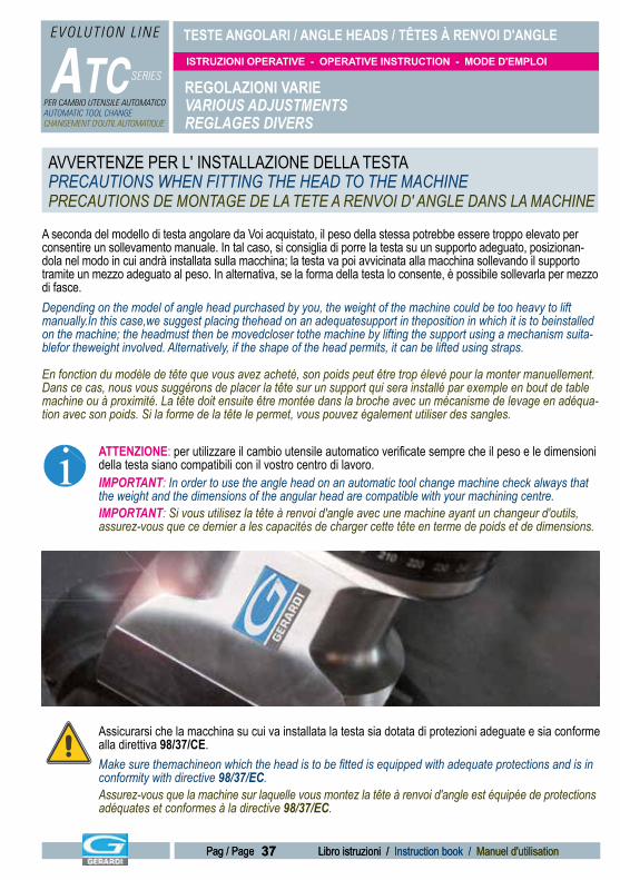
TESTE ANGOLARI / ANGLE HEADS / TÊTES À RENVOI D'ANGLE
ATC SERIES
EVOLUTION L INE
PER CAMBIO UTENSILE AUTOMATICOAUTOMATIC TOOL CHANGECHANGEMENT D'OUTIL AUTOMATIQUE
ISTRUZIONI OPERATIVE - OPERATIVE INSTRUCTION - MODE D'EMPLOI
37 Libro istruzioni / Instruction book / Manuel d'utilisationPag / Page 37 Libro istruzioni / Instruction book / Manuel d'utilisationPag / Page
REGOLAZIONI VARIEVARIOUS ADJUSTMENTSREGLAGES DIVERS
A seconda del modello di testa angolare da Voi acquistato, il peso della stessa potrebbe essere troppo elevato per consentire un sollevamento manuale. In tal caso, si consiglia di porre la testa su un supporto adeguato, posizionan-dola nel modo in cui andrà installata sulla macchina; la testa va poi avvicinata alla macchina sollevando il supporto tramite un mezzo adeguato al peso. In alternativa, se la forma della testa lo consente, è possibile sollevarla per mezzo di fasce.Depending on the model of angle head purchased by you, the weight of the machine could be too heavy to lift manually.In this case,we suggest placing thehead on an adequatesupport in theposition in which it is to beinstalled on the machine; the headmust then be movedcloser tothe machine by lifting the support using a mechanism suita-blefor theweight involved. Alternatively, if the shape of the head permits, it can be lifted using straps.
En fonction du modèle de tête que vous avez acheté, son poids peut être trop élevé pour la monter manuellement. Dans ce cas, nous vous suggérons de placer la tête sur un support qui sera installé par exemple en bout de table machine ou à proximité. La tête doit ensuite être montée dans la broche avec un mécanisme de levage en adéqua-tion avec son poids. Si la forme de la tête le permet, vous pouvez également utiliser des sangles.
Assicurarsi che la macchina su cui va installata la testa sia dotata di protezioni adeguate e sia conforme alla direttiva 98/37/CE. Make sure themachineon which the head is to be fitted is equipped with adequate protections and is in conformity with directive 98/37/EC.Assurez-vous que la machine sur laquelle vous montez la tête à renvoi d'angle est équipée de protections adéquates et conformes à la directive 98/37/EC.
ATTENZIONE: per utilizzare il cambio utensile automatico verificate sempre che il peso e le dimensionidella testa siano compatibili con il vostro centro di lavoro.IMPORTANT: In order to use the angle head on an automatic tool change machine check always that the weight and the dimensions of the angular head are compatible with your machining centre.IMPORTANT: Si vous utilisez la tête à renvoi d'angle avec une machine ayant un changeur d'outils, assurez-vous que ce dernier a les capacités de charger cette tête en terme de poids et de dimensions.
i
AVVERTENZE PER L' INSTALLAZIONE DELLA TESTAPRECAUTIONS WHEN FITTING THE HEAD TO THE MACHINEPRECAUTIONS DE MONTAGE DE LA TETE A RENVOI D' ANGLE DANS LA MACHINE
TESTE ANGOLARI / ANGLE HEADS / TÊTES À RENVOI D'ANGLE
ATC SERIES
EVOLUTION L INE
PER CAMBIO UTENSILE AUTOMATICOAUTOMATIC TOOL CHANGECHANGEMENT D'OUTIL AUTOMATIQUE
ISTRUZIONI OPERATIVE - OPERATIVE INSTRUCTION - MODE D'EMPLOI
38 Libro istruzioni / Instruction book / Manuel d'utilisationPag / Page
UTILIZZOUSEUTILISATION
Prima della messa in funzione leggere attentamente le indicazioni di sicurezza (Pag. 16)Before starting the machine, carefully read the safety instructions (Pag. 16)Avant d'utiliser la tête à renvoi d'angle, lisez les instructions de sécurité (Pag. 16)
Montare la testa sulla macchina ed eseguire una corretta regolazione (Pag. 28). Montati gli utensili (Pag. 37) si può procedere con l’utilizzo.Fit the head on the machine and adjust correctly (Pag. 28). After fitting the tools (Pag. 37), the machine can be used.Installez la tête dans la machine et réglez-la correctement (Pag. 28). Après avoir monté l'outil (Pag. 37), vous pouvez l'utiliser.
i ATTENZIONE: prima di mettere in funzione la testa ad angolo, verificare il senso di rotazione da dare al mandrino macchina per far si che l ’utensile ruoti nella direzione di taglio corretta.IMPORTANT: before starting up the angle head, check spindle rotation direction to ensure the tool turns in the correct cutting direction.IMPORTANT: Avant d'utiliser la tête à renvoi d'angle, assurez-vous que la broche tourne dans le bon sens de coupe.
Verificare preventivamente il corretto serraggio degli utensili. Make sure before hand that the tools are properly fitted.Assurez-vous que l'outil est correctement monté.
Nel caso all’avviamento si avverta una rumorosità anomala o vibrazioni, interrompere la lavorazione e contattare il nostro Ufficio Tecnico.If you hear a strange noise or vibrations on starting the machine, interrupt operation and contact our Technical Department.Si vous entendez un bruit anormal ou qu'il y a des vibrations importantes lorsque vous démarrez la tête à renvoi d'angle, arrêtez les opérations et contactez notre Service d'Intervention Technique.
Ogni uso diverso da quelli previsti è da considerarsi non autorizzato. La GERARDI SPA non si assume nessuna responsabilità riguardo a danni a persone, cose od alla testa ad angolo stessa derivanti da un uso improprio.All uses other than those intended shall be deemed unauthorised. GERARDI SPA cannot accept any liabiliy for injury to persons or damage to things or tothe angle head caused by improper machine use.Tout usage autre que ceux indiqués est prohibé.GERARDI SPA n'acceptera aucune responsabilité sur des dégâts ou des blessures en cas d'usage inapproprié de la tête à renvoi d'angle.
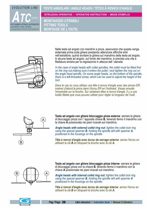
TESTE ANGOLARI / ANGLE HEADS / TÊTES À RENVOI D'ANGLE
ATC SERIES
EVOLUTION L INE
PER CAMBIO UTENSILE AUTOMATICOAUTOMATIC TOOL CHANGECHANGEMENT D'OUTIL AUTOMATIQUE
ISTRUZIONI OPERATIVE - OPERATIVE INSTRUCTION - MODE D'EMPLOI
39 Libro istruzioni / Instruction book / Manuel d'utilisationPag / Page 39 Libro istruzioni / Instruction book / Manuel d'utilisationPag / Page
MONTAGGIO UTENSILIFITTING TOOLSMONTAGE DE L'OUTIL
Nelle teste ad angolo con mandrini a pinza, assicurarsi che questa venga sistemata prima sulla ghiera prestando attenzione affinché entri nell’estrattore; quindi avvitare la ghiera sul mandrino della testa ad angolo. In alcune teste ad angolo, sul fondo del mandrino, è prevista una vite a filettatura sinistra per la regolazione in altezza dell ’utensile.
In the case of angle heads with collet spindles, the collet must be fitted first on the ring nut,making sure it enters the puller; next tighten the ring nut on the angle head spindle. On some angle heads, on the bottom of the spindle, there is a left-threaded screw, which can be used to adjust the height of the tool.Dans le cas où vous utilisez une tête à renvoi d'angle avec des pinces ER, insérez d'abord la pince dans l'écrou ER en l'inclinant. Vissez ensuite l'ensemble sur la broche. Sur certaines têtes à renvoi d'angle, il y a une butée filetée que vous pouvez utiliser pour régler la longueur de l'outil.
Teste ad angolo con ghiere bloccaggio pinza esterne: serrare la ghiera di bloccaggio pinza con l ’apposita chiave B, tenendo fermo il mandrino con la chiave A posizionata nei piani ricavati sul mandrino.Angle heads with external collet ring nut: tighten the collet lock ring using the special spanner B, holding the spindle still with spanner A, positioned in the housings on the spindle.
Tête à renvoi d'angle avec écrou de serrage externe: serrez l'écrou en utilisant la clé B en bloquant la broche avec la clé A.
Teste ad angolo con ghiere bloccaggio pinza interne: serrare la ghiera di bloccaggio pinza con la chiave B, tenendo fermo il mandrino con lachiave A posizionata nei piani ricavati sul mandrino.Angle heads with internal collet ring nut: tighten the collet lock ring using the special spanner B, holding the spindle still with spanner A positioned in the housings on the spindle.
Tête à renvoi d'angle avec écrou de serrage interne: serrez l'écrou en utilisant la clé B en bloquant la broche avec la clé A.
A
B
AB
TESTE ANGOLARI / ANGLE HEADS / TÊTES À RENVOI D'ANGLE
ATC SERIES
EVOLUTION L INE
PER CAMBIO UTENSILE AUTOMATICOAUTOMATIC TOOL CHANGECHANGEMENT D'OUTIL AUTOMATIQUE
ISTRUZIONI OPERATIVE - OPERATIVE INSTRUCTION - MODE D'EMPLOI
40 Libro istruzioni / Instruction book / Manuel d'utilisationPag / Page
MANUTENZIONEMAINTENANCEMAINTENANCE
Pulire periodicamente la testa dai residui delle lavorazioni ed eliminare il liquido refrigerante presente nei condotti.Periodically clean the headand remove any machining residues and drain the coolant liquid from the pipes.Nettoyez périodiquement la tête, enlevez les résidus d'usinage et videz le liquide de coupe des tuyaux.
Le teste ad angolo sono fornite complete di lubrificante. Durante le prime ore di lavoro si possono verificare delle perdite di parte del lubrificante dovute ad una eccessiva quantità presente nel corpo testa o nei labirinti di protezione.Ogni 500 ore di lavoro aggiungere 20 g di grasso KLUBER CENTOPLEX CX4/375AU dal tappo presente sul corpo testa per le teste serie F90 o dalla vite per le teste FMU. La struttura compatta, il tipo di lubrificantee l’elevata velocità possono comportare alle teste temperaturedi oltre 60° senza alternarne le caratteristiche di funzionamento.The angle heads are supplied complete with lubricant. During the first hours of work, part of the lubricant could leak away due to excessive quantities in the head body and in the protection labyrinth seal. Every 500 hours of operation, add 20 g of KLUBER CENTOPLEX CX4/375AU grease through the cap on the body for the F90 series or through the screw in the case of the FMU heads. The compact structure, the type of lubricant and the high speed can raise head temperature to over 60° without altering its operating characteristics.
La tête à renvoi d'angle est livrée graissée. Durant les premières heures d'usinage, un peu de graisse peut se liquéfier et fuir par les joints de la broche. Ce phénomène est normal. Toutes les 500 heures de fonctionnement, graissez la tête avec 20 g de KLUBER CENTOPLEX CX4/375AU sur le graisseur placé sur le corps pour les têtes F90 ou en enlevant les deux vis pour les têtes FMU. La structure compacte, le type de lubrifiant et les hautes vitesses font que la température peut atteindre 60°c sans altérer le mécanisme interne.
I lubrificanti sono altamente inquinanti.Non disperdere nell ambiente tali sostanze, ne’ eventuali materiali con i quali siano venute a contatto, ma consegnarli alle apposite società per lo smaltimento dei rifiuti.The lubricants used are highly polluting. Do not throw them or any materials with which they have come into contact away into the environment. Ensure disposal through specially qualified disposal channels.La graisse utilisée est très polluante. Ne la jetez pas, ou ne jetez aucun composant qui en est enduit dans la nature. Recyclez-la dans les réseaux appropriés.
PULIZIACLEANINGNETTOYAGE
LUBRIFICAZIONELUBRICATIONGRAISSAGE
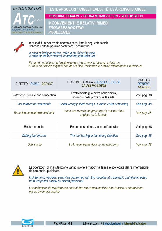
TESTE ANGOLARI / ANGLE HEADS / TÊTES À RENVOI D'ANGLE
ATC SERIES
EVOLUTION L INE
PER CAMBIO UTENSILE AUTOMATICOAUTOMATIC TOOL CHANGECHANGEMENT D'OUTIL AUTOMATIQUE
ISTRUZIONI OPERATIVE - OPERATIVE INSTRUCTION - MODE D'EMPLOI
41 Libro istruzioni / Instruction book / Manuel d'utilisationPag / Page 41 Libro istruzioni / Instruction book / Manuel d'utilisationPag / Page
INCONVENIENTI E RELATIVI RIMEDITROUBLESHOOTING PROBLEMES
In caso di funzionamento anomalo,consultare la seguente tabella. Nel caso il difetto persista contattare il costruttore.
In case of faulty operation, refer to the following table. In case the fault continues, contact the manufacturer.
En cas de problème de fonctionnement, consultez le tableau ci-dessous. Si vous ne trouvez toujours pas de solution, contactez le Service d'Intervention Technique.
Le operazioni di manutenzione vanno svolte a macchina ferma e scollegata dall ’alimentazione da personale qualificato.
Maintenance operations must be performed with the machine at a standstill and disconnected from the power supply by skilled personnel.
Les opérations de maintenance doivent être effectuées machine hors tension et débranchée par du personnel qualifié.
DIFETTO - FAULT - DEFAUT POSSIBILE CAUSA - POSSIBLE CAUSE CAUSE POSSIBLE
RIMEDIOREMEDY REMEDE
Rotazione utensile non concentica Errato montaggio pinze nella ghiera,sporcizia nella pinza o nella sede. Vedi pag. 38
Tool rotation not concentric Collet wrongly fitted in ring nut, dirt in collet or housing See pag. 38
Mauvaise concentricité de l'outil. Pince mal montée ou présence de résidus dans la pince ou la broche. Voir pag. 38
Rottura utensile Errato senso di rotazione dell'utensile Vedi pag. 38
Drilling tool broken The tool turning in the wrong direction See pag. 38
Outil cassé La broche tourne dans le mauvais sens Voir pag. 38
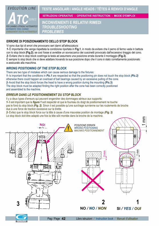
TESTE ANGOLARI / ANGLE HEADS / TÊTES À RENVOI D'ANGLE
ATC SERIES
EVOLUTION L INE
PER CAMBIO UTENSILE AUTOMATICOAUTOMATIC TOOL CHANGECHANGEMENT D'OUTIL AUTOMATIQUE
ISTRUZIONI OPERATIVE - OPERATIVE INSTRUCTION - MODE D'EMPLOI
42 Libro istruzioni / Instruction book / Manuel d'utilisationPag / Page
NO!
1 mm
1 mm
0 mm
INCONVENIENTI E RELATIVI RIMEDITROUBLESHOOTING PROBLEMES
ERRORE DI POSIZIONAMENTO DELLO STOP BLOCKVi sono due tipi di errori che provocano seri danni all'attrezzatura:1- È importante che venga rispettata la condizione riportata in Fig.1, in modo da evitare che il perno di fermo vada in battuta con lo stop block (Fig.2); se così fosse si avrebbe un sovraccarico dei cuscinetti provocato dall'eccessivo tiraggio del cono.2- Evitare che lo stop block costringa la testa ad assumere una posizione errata durante il montaggio (Fig.3). È sempre lo stop block che si deve adattare trovando la sua posizione dopo che il cono è stato correttamente posizionato e assicurato alla macchina.
WRONG POSITIONING OF THE STOP BLOCKThere are two type of mistakes which can cause serious damage to the fixtures:1- Is important that the conditions in Pic.1 are respected so that the positioning pin does not touch the stop block (Pic.2) otherwise there could happen an overload of ball bearings caused by an excessive pulling of the cone.2- Avoid that the stop block forces the head to have a wrong position during the mounting (Pic.3)The stop block must be adapted finding the right position after the cone has been correctly positioned and assembled to the machine.
ERREUR DANS LE POSITIONNEMENT DU STOP BLOCKIl y a deux types d'erreurs qui peuvent engendrer des dommages sérieux aux supports:1- Il est important que la figure 1 soit respectèr et que le fourreau du doigt de positionnement ne touche pas le fond du stop block (Fig. 2). Sinon il est possible qu'une surchage survienne sur les roulements de broche due à une force de traction excessive sur la tirette.2- Evitez que le stop block force sur la tête à cause d'une mauvaise position de montage (Fig. 3)Le stop block doit être adapté une fois la tête sôit montée dans la broche de la machine.
NO!
1 mm
1 mm
0 mm
SI / YES / OUINO / NO / NON
POSIZIONE ERRATA WRONG POSITIONINGMAUVAIS POSITIONNEMENT
123
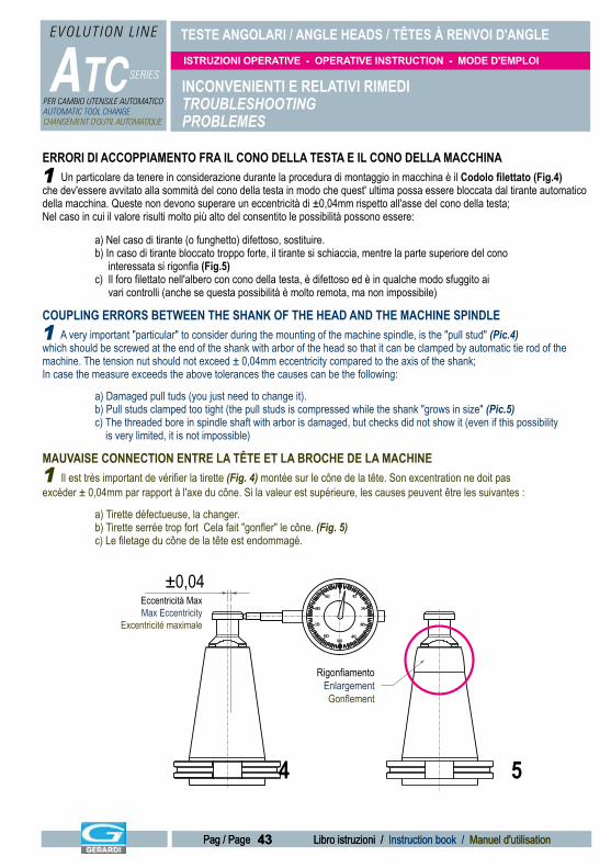
TESTE ANGOLARI / ANGLE HEADS / TÊTES À RENVOI D'ANGLE
ATC SERIES
EVOLUTION L INE
PER CAMBIO UTENSILE AUTOMATICOAUTOMATIC TOOL CHANGECHANGEMENT D'OUTIL AUTOMATIQUE
ISTRUZIONI OPERATIVE - OPERATIVE INSTRUCTION - MODE D'EMPLOI
43 Libro istruzioni / Instruction book / Manuel d'utilisationPag / Page 43 Libro istruzioni / Instruction book / Manuel d'utilisationPag / Page
RigonfiamentoEnlargementGonflement
Eccentricità MaxMax Eccentricity
Excentricité maximale
±0,04
ERRORI DI ACCOPPIAMENTO FRA IL CONO DELLA TESTA E IL CONO DELLA MACCHINA Un particolare da tenere in considerazione durante la procedura di montaggio in macchina è il Codolo filettato (Fig.4)che dev'essere avvitato alla sommità del cono della testa in modo che quest' ultima possa essere bloccata dal tirante automatico della macchina. Queste non devono superare un eccentricità di ±0,04mm rispetto all'asse del cono della testa;Nel caso in cui il valore risulti molto più alto del consentito le possibilità possono essere:
a) Nel caso di tirante (o funghetto) difettoso, sostituire. b) In caso di tirante bloccato troppo forte, il tirante si schiaccia, mentre la parte superiore del cono interessata si rigonfia (Fig.5) c) Il foro filettato nell'albero con cono della testa, è difettoso ed è in qualche modo sfuggito ai vari controlli (anche se questa possibilità è molto remota, ma non impossibile)
COUPLING ERRORS BETWEEN THE SHANK OF THE HEAD AND THE MACHINE SPINDLE A very important "particular" to consider during the mounting of the machine spindle, is the "pull stud" (Pic.4)which should be screwed at the end of the shank with arbor of the head so that it can be clamped by automatic tie rod of the machine. The tension nut should not exceed ± 0,04mm eccentricity compared to the axis of the shank;In case the measure exceeds the above tolerances the causes can be the following:
a) Damaged pull tuds (you just need to change it). b) Pull studs clamped too tight (the pull studs is compressed while the shank "grows in size" (Pic.5) c) The threaded bore in spindle shaft with arbor is damaged, but checks did not show it (even if this possibility is very limited, it is not impossible)
MAUVAISE CONNECTION ENTRE LA TÊTE ET LA BROCHE DE LA MACHINE Il est très important de vérifier la tirette (Fig. 4) montée sur le cône de la tête. Son excentration ne doit pas excéder ± 0,04mm par rapport à l'axe du cône. Si la valeur est supérieure, les causes peuvent être les suivantes :
a) Tirette défectueuse, la changer. b) Tirette serrée trop fort Cela fait "gonfler" le cône. (Fig. 5) c) Le filetage du cône de la tête est endommagé.
INCONVENIENTI E RELATIVI RIMEDITROUBLESHOOTING PROBLEMES
1
1
1
4 5
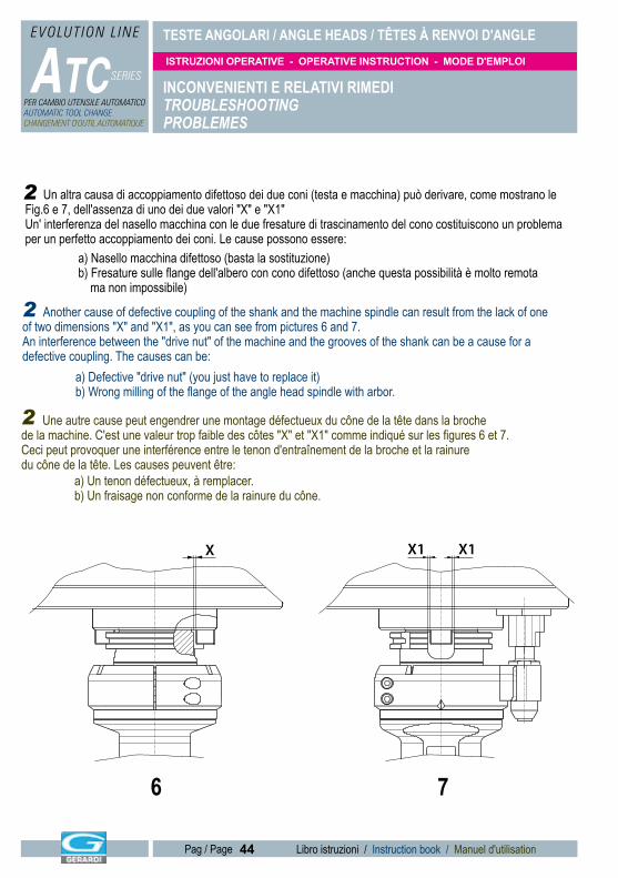
TESTE ANGOLARI / ANGLE HEADS / TÊTES À RENVOI D'ANGLE
ATC SERIES
EVOLUTION L INE
PER CAMBIO UTENSILE AUTOMATICOAUTOMATIC TOOL CHANGECHANGEMENT D'OUTIL AUTOMATIQUE
ISTRUZIONI OPERATIVE - OPERATIVE INSTRUCTION - MODE D'EMPLOI
44 Libro istruzioni / Instruction book / Manuel d'utilisationPag / Page
Un altra causa di accoppiamento difettoso dei due coni (testa e macchina) può derivare, come mostrano le Fig.6 e 7, dell'assenza di uno dei due valori "X" e "X1" Un' interferenza del nasello macchina con le due fresature di trascinamento del cono costituiscono un problema per un perfetto accoppiamento dei coni. Le cause possono essere: a) Nasello macchina difettoso (basta la sostituzione) b) Fresature sulle flange dell'albero con cono difettoso (anche questa possibilità è molto remota ma non impossibile)
Another cause of defective coupling of the shank and the machine spindle can result from the lack of one of two dimensions "X" and "X1", as you can see from pictures 6 and 7.An interference between the "drive nut" of the machine and the grooves of the shank can be a cause for a defective coupling. The causes can be: a) Defective "drive nut" (you just have to replace it) b) Wrong milling of the flange of the angle head spindle with arbor.
Une autre cause peut engendrer une montage défectueux du cône de la tête dans la broche de la machine. C'est une valeur trop faible des côtes "X" et "X1" comme indiqué sur les figures 6 et 7.Ceci peut provoquer une interférence entre le tenon d'entraînement de la broche et la rainure du cône de la tête. Les causes peuvent être: a) Un tenon défectueux, à remplacer. b) Un fraisage non conforme de la rainure du cône.
X X1 X1
INCONVENIENTI E RELATIVI RIMEDITROUBLESHOOTING PROBLEMES
2
2
2
6 7
TESTE ANGOLARI / ANGLE HEADS / TÊTES À RENVOI D'ANGLE
ATC SERIES
EVOLUTION L INE
PER CAMBIO UTENSILE AUTOMATICOAUTOMATIC TOOL CHANGECHANGEMENT D'OUTIL AUTOMATIQUE
ISTRUZIONI OPERATIVE - OPERATIVE INSTRUCTION - MODE D'EMPLOI
45 Libro istruzioni / Instruction book / Manuel d'utilisationPag / Page 45 Libro istruzioni / Instruction book / Manuel d'utilisationPag / Page
Non disperdere la testa ed eventuali suoi componenti nell ’ambiente.Do not throw the head or any of its component parts away into the environment.Ne jetez ni la tête ni aucun de ses composants dans la nature.
In caso di dismissione della testa occorre rottamare i vari componenti (cioè rendere inoperante la testa ) e smaltire il tutto presso un centro specializzato.In case the headhas to be decommissioned, the various components must be crapped (the head must be made inoperative) and disposed of through authorised channels.
Si la tête à renvoi d'angle doit être démantelée, les différents composants doivent être démontés et recyclés par des canaux appropriés.
INCONVENIENTI E RELATIVI RIMEDITROUBLESHOOTING PROBLEMES
L'ultima causa di accoppiamento difettoso dei due coni è rappresentata dal fatto che uno dei due coni non sia perfetto. Normalmente ciò si verifica in caso di macchine molto vecchie dove il cono della macchina è fortemente rovinato dalle numerose lavorazioni pesanti e dall'interpolazione di trucioli tra cono macchina e mandrini nel corso degli anni. In tutti questi casi, non essendoci un contatto perfetto tra i due coni, le teste oscillano durante la rotazione e in molti casi tale oscillazione si avverte perfino ad occhio nudo. Inoltre, le attrezzature non riescono a lavorare e vibrano per una totale assenza di rigidità
Also the fact that either the shank or the spindle are not perfect can be a problem.This can happen in case of very old machine tools where the spindle is spoiled due to heavy machining or the interposition of chips between the shank and the spindle during the years. In these cases, since there is not perfect coupling between the shank and the spindle, the head swings during rotation and often it can also be seen with the naked eye. The head cannot machine the work-piece and vibrates due to the lack of rigidity
Il peut également arriver que le cône de la tête ou la broche de la machine ne soit pas parfait.Ceci peut arriver sur des têtes ou des broches de machine anciennes, du à des efforts d'usinage excessif ou des résidus de copeaux mal nettoyés.Dans ce cas, comme le contact entre le cône de la tête et la broche n'est pas bon, il y aura des oscillations durant l'usinage même perceptibles à l'oeil nu. Il y aura alors des vibrations et la pièce ne pourra être usinée correctement.
3
3
3
SMANTELLAMENTOSCRAPPINGMISE AU REBUT
TESTE ANGOLARI / ANGLE HEADS / TÊTES À RENVOI D'ANGLE
ATC SERIES
EVOLUTION L INE
PER CAMBIO UTENSILE AUTOMATICOAUTOMATIC TOOL CHANGECHANGEMENT D'OUTIL AUTOMATIQUE
ISTRUZIONI OPERATIVE - OPERATIVE INSTRUCTION - MODE D'EMPLOI
46 Libro istruzioni / Instruction book / Manuel d'utilisationPag / Page
La GERARDI SpA garantisce per un periodo di 12 mesi dalla data di acquisto, il regolare funzionamento degli apparecchi, la buona qualità dei materiali impiegati e la perfetta costruzione.
Per tale garanzia la GERARDI SpA si impegna a provvedere alla riparazione e sostituzione di quelle parti che risultassero difettose per impiego di cattivo materiale o per vizio di costruzione,
purchè dette parti vengano consegnate in porto franco al suo stabilimento.Tutti i componenti rimossi nel corso di una riparazione in garanzia, divengono di proprietà della GERARDI SPA.
Tutti i componenti sostituiti in garanzia nei 12 mesi contrattuali godranno del periodo di garanzia residua.La garanzia non si estende a particolari di usura quali tenute e cuscinetti nè a guasti o rotture derivanti da
imperizia, trascuratezza o cattivo uso dell’apparecchio da parte dell’acquirente, e cessa qualora i pagamenti non vengono effetuati dal compratore alle scadenze convenute e quando l’apparecchio o parte di esso sia stato
modificato o riparato senza l’autorizzazione della GERARDI SpA.
The GERARDI SpA heads are guaranteed for 12 months from the date of purchase.During this period parts proved to be faulty or unserviceable as a consequence of defective material or faults of
design or manufacture will be repaired or substituted provided they are returned to the factory carriage free.Allcomponents removed during repair under warranty shall become the property of GERARDI SPA.
All components replaced during the 12 months warranty period shall be covered by thefurther periodof warranty.The warranty does not cover damaged seals and bearings and any damages or faults resulting from negligence or
incorrect use by the purchaser and ceases if payments are not effected on the dates agreed or the heads orparts thereof have been modifier or repaired without GERARDI’s authorization.
In caso di rottura la GERARDI SpA consiglia di ritornare la testa presso la propria officina per una sistemazione ottimale. Nel caso il cliente volesse procedere autonomamente alla riparazione, è necessario consultare il foglio
con l’esploso della testa che è sempre allegato alla scheda tecnica. In questo caso, ovviamente, viene a cessare ogni garanzia sulla testa manomessa.
Nell ’eventualità di un ordine di ricambi inviare via fax il documento riportato nella pagina seguente che deve essere compilato in tutte le sue parti.
In the event of failure GERARDI SpA suggests to return the head to us for repair.If you prefer to repair by yourself, please consult the paper with the exploded head, is always attached
to the technical sheet. In this case our warranty expires.If you have to order spare parts, fax the document shown on the next page,
having first filled it in completely.
PARTI DI RICAMBIO / SPARE PART / PIECES DETACHEES
Les têtes GERARDI SpA sont garanties 12 mois à compter de la date d'achat. Pendant cette période, toute pièce présentant un défaut de conception ou de fabrication seront réparées ou remplacées à l'usine gratuitement.
Le transport à l'usine reste à votre charge.Tous les composants remplacés pendant la garantie sont la propriété de GERARDI SpA.
Tous les composants remplacés pendant la période de 12 mois verront leur garantie prolongée.La garantie ne prend pas en compte les joints ni les roulements endommagés par une mauvaise utilisation ou s'ils
ont été remplacés sans autorisation par GERARDI.
Dans l'éventualité d'un défaut , nous vous suggérons de nous retourner la tête pour réparation. Si vous préférez la réparer vous-même, consultez la vue explosée, accompagnant chaque tête.
Dans ce cas votre garantie expire. Si vous avez besoin de pièces détachées, faxez le document de la page suivante en l'ayant préalablement remplie.
GARANZIA E PARTI DI RICAMBIOWARRANTY AND SPARE PARTSGARANTIE ET PIECES DETACHEES

SERVIZIO RICAMBI / SPARE PARTS SERVICE / SERVICE PIÈCES DE RECHANGE
FAX +39.0331.301534Spedizione:Shipping:Expédition:
TESTA:HEAD:TETE:
N° MATRICOLA:SERIAL NUMBER:NUMÉRO DE SÉRIE:
CODICE:CODE:CODE:
QUANTITA':QUANTITY:QUANTITE:
NOTE / NOTES / NOTES:
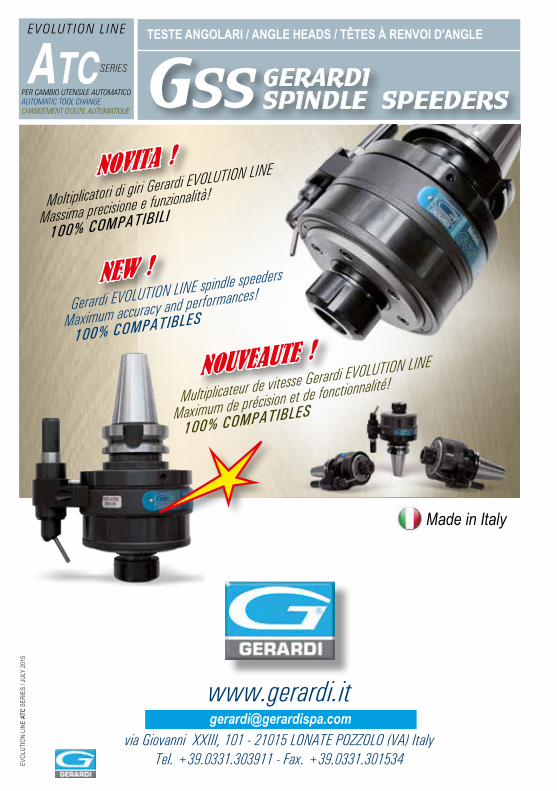
TESTE ANGOLARI / ANGLE HEADS / TÊTES À RENVOI D'ANGLE
ATC SERIES
EVOLUTION L INE
PER CAMBIO UTENSILE AUTOMATICOAUTOMATIC TOOL CHANGECHANGEMENT D'OUTIL AUTOMATIQUE
SERIES
www.gerardi.it
via Giovanni XXIII, 101 - 21015 LONATE POZZOLO (VA) ItalyTel. +39.0331.303911 - Fax. +39.0331.301534
EVOL
UTIO
N LIN
E AT
C SE
RIES
/ JUL
Y 20
15
Made in Italy
NOUVEAUTE !
NOVITA !
NEW !
Moltiplicatori di giri Gerardi EVOLUTION LINE
Massima precisione e funzionalità!
100% COMPATIBILI
Gerardi EVOLUTION LINE spindle speeders
Maximum accuracy and performances!
100% COMPATIBLES
Multiplicateur de vitesse Gerardi EVOLUTION LINE
Maximum de précision et de fonctionnalité!
100% COMPATIBLES
GSS GERARDI SPINDLE SPEEDERS