
513 COMMISSION - Hawaii
42
LINDA LINGLE WILLIAM J AILA, JR. GOVERNOR OF HAWPJI CI-IAJRPERSON WILLIAM D. BALFOUR, JR. SUMNER ERDMAN LORETTA J. FUDDY, A.C.S.W., MPH. NEAL S. FUJIWARA LAWRENCE H. MIIKE, M.D., J.D. TED YAMAMURA STATE OF HAWAII WH±IAMM.TAM DEPARTMENT OF LAND AND NATURAL RESOURCES COMMISSION ON WATER RESOURCE MANAGEMENT P.O. BOX 621 HONOLULU. HAWAII 968.09 STAFF SUBMITTAL COMMISSION ON WATER RESOURCE MANAGEMENT May 16, 2012 Honolulu, Hawaii Application for Stream Channel Alteration Permit (SCAP.2621.3) for Temporary By-Pass Roads and Replacement of Makaha Bridges 3 and 3A, Makaha Stream, Makaha, Oahu (TMKs: (1) 8-4-001:012, 8-4-002:045 and 47, 8-4-008:020 and 8-4-018:014) APPLICANT: LANDOWNERS: Edwin Sniffen, Highways Administrator City and County of Honolulu Department of Transportation Dept. of Parks and Recreation (DPR) 869 Punchbowl Street, Room 513 (TMKs: (1) 8-4-001:012 and 8-4-002:047) Honolulu, HI 96813 HRT Kili Drive LLC Farrington Highway Waianae, HI 96792 (TMK: (1) 8-4-002:045) Moana Kea Among and Amalia Barboza 84-445 Farrington Highway Waianae, HI 96792 (TMK: (1) 8-4-008:020) Robert C. Palmer 84-45 0 Farrington Highway Waianae, HI 96792 (TMK: (1) 8-4-018:014) SUMMARY OF REQUEST: Application for Stream Channel Alteration Permit (SCAP.262 1.3) for temporary a by-pass road and replacement of Makaha Bridges 3 and 3A in Makaha, Oahu (TMKs: (1) 8-4-1-001:012, 8-4-002:045 and 47, 8-4-008:020 and 8-4-018:014). LOCATION: See Exhibits IA, 1B, 1C, and 1D. Dl
Transcript of 513 COMMISSION - Hawaii
LINDA LINGLE WILLIAM J AILA, JR.GOVERNOR OF HAWPJI CI-IAJRPERSON
WILLIAM D. BALFOUR, JR.SUMNER ERDMAN
LORETTA J. FUDDY, A.C.S.W.,MPH.
NEAL S. FUJIWARALAWRENCE H. MIIKE, M.D., J.D.
TED YAMAMURA
STATE OF HAWAII WH±IAMM.TAM
DEPARTMENT OF LAND AND NATURAL RESOURCESCOMMISSION ON WATER RESOURCE MANAGEMENT
P.O. BOX 621HONOLULU. HAWAII 968.09
STAFF SUBMITTAL
COMMISSION ON WATER RESOURCE MANAGEMENT
May 16, 2012Honolulu, Hawaii
Application for Stream Channel Alteration Permit (SCAP.2621.3) forTemporary By-Pass Roads and Replacement of Makaha Bridges 3 and 3A, Makaha Stream, Makaha,
Oahu (TMKs: (1) 8-4-001:012, 8-4-002:045 and 47, 8-4-008:020 and 8-4-018:014)
APPLICANT: LANDOWNERS:
Edwin Sniffen, Highways Administrator City and County of HonoluluDepartment of Transportation Dept. of Parks and Recreation (DPR)869 Punchbowl Street, Room 513 (TMKs: (1) 8-4-001:012 and 8-4-002:047)Honolulu, HI 96813
HRT Kili Drive LLCFarrington HighwayWaianae, HI 96792(TMK: (1) 8-4-002:045)
Moana Kea Among and Amalia Barboza84-445 Farrington HighwayWaianae, HI 96792(TMK: (1) 8-4-008:020)
Robert C. Palmer84-45 0 Farrington HighwayWaianae, HI 96792(TMK: (1) 8-4-018:014)
SUMMARY OF REQUEST:
Application for Stream Channel Alteration Permit (SCAP.262 1.3) for temporary a by-pass road andreplacement of Makaha Bridges 3 and 3A in Makaha, Oahu (TMKs: (1) 8-4-1-001:012, 8-4-002:045 and47, 8-4-008:020 and 8-4-018:014).
LOCATION: See Exhibits IA, 1B, 1C, and 1D.
Dl

Staff Submittal May 16, 2012
BACKGROUND:
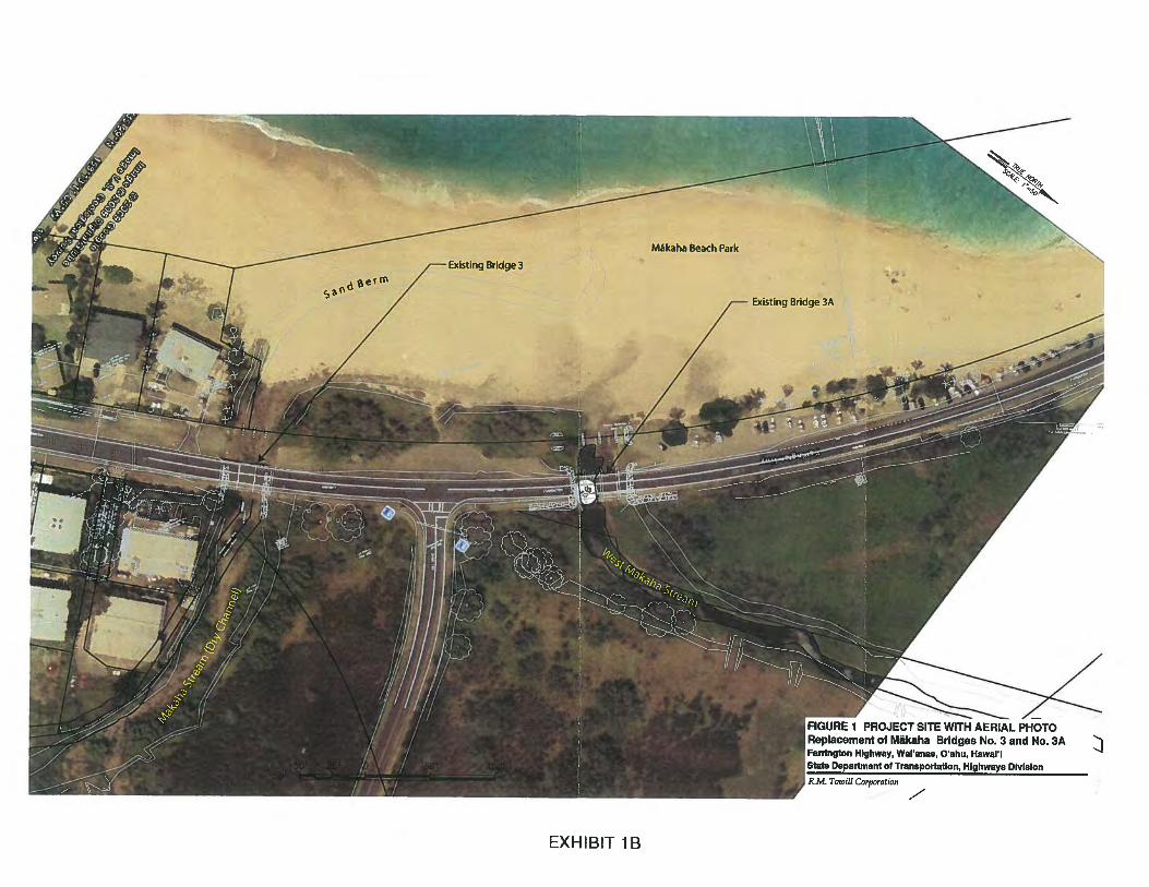
Farrington Highway is a two-lane arterial with 11-foot wide lanes and three-foot wide paved shoulders.Makaha Bridges 3 and 3A support two 11-foot wide lanes with a two-foot wide shoulder on the makaiside of the bridge and a one-foot wide shoulder on the mauka side. A four-foot wide walkway is locatedon the mauka side of both bridges. Both wooden bridges were built in 1937. See Exhibits 1A and lB.
The Hawaii Department of Transportation (HDOT) proposes to replace the two timber bridges alongFarrington Highway in Makaha, Oahu to comply with current design standards of the AmericanAssociation of State Highway and Transportation Officials (AASHTO) and HDOT. The design willaddress current bridge deficiencies in substructure and superstructure conditions, hydraulic capacity,bridge width and shoulder areas. The replacement bridges will:
• Feature reinforced concrete structures to eliminate the potential for increased maintenancecosts associated with aging wooden bridges.
• Increase travel-way widths and provide adequate shoulder areas.• Include other improvements such as bridge railings and guardrails.• Expand pedestrian and bicycle facilities along the bridges and approaches.• Provide stream flow capacity to accommodate 100-year flood events.
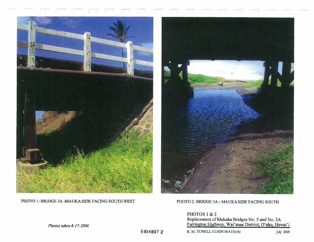
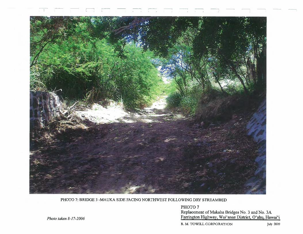
Makaha Stream is an intermittent stream that originates in the western slopes of the Waianae mountainrange deep in Makaha Valley. Makaha Stream flows under Bridge 3 and terminates behind a sand berm.at Makaha Beach Park. West Makaha Stream arises on the south slope of the Puukeaau mountain rangeand eventually flows under Bridge 3A. It is a relatively short intermittent stream that terminates in anapproximately 100-foot long muliwai (coastal estuarine pond) along West Makaha Stream on the maukaside of Farrington Highway. Neither stream has a permanent surface connection to the ocean. The twostream beds connect to each other on the makai side of Farrington Highway. Water normally flows in thisarea only after heavy rains. See Exhibit 2 (Photos 1-7).
On December 7, 2004, the State Historic Preservation Division (SHPD) accepted the applicant’sArchaeological Monitoring Plan (AMP) for the project.
On July 9, 2007, SHPD accepted the applicant’s 2006 Burial Treatment Plan for the project.
On February 17, 2010, SHPD approved the applicant’s Archaeological Data Recovery Plan to address thehandling of two bone fragments and other archaeological resources (railroad remnants and two timberframed bridges, #3 and 3A) found at the project site.
On August 28, 2010, SHPD approved the applicant’s Historic American Engineering Record (HAER) HI-90 and HI-91, Makaha Bridges 3 and 3A and ORL Trestle Ruins which photo documented and describedthe architecture and history of the Makaha Bridges.
On April 29, 2011, HDOT submitted the Final Environmental Assessment (FEA) and Finding of NoSignificant Impact (FONSI) of Makaha Bridges No. 3 and No. 3A to the Office of Environmental QualityControl (OEQC) for its review and approval.
On May 23, 2011, OEQC approved and published the FEA and FONSI for the proposed project.
On October 3, 2011, Commission staff met with Keith and Juliana Kohls, 84-452 Farrington Highway(TMK: (1) 4-8-018:122) to discuss the Kohls’ concerns regarding the design details for the new bridge,the retaining wall design, stream hydraulics and flooding concerns. Commission staff informed the Kohis
2
Staff Submittal May 16, 2012
that the stream hydraulics and the engineering for bridge and retaining wall should be addressed byHDOT engineers and the City and County Department of Planning and Permitting as part of the SMApermitting process.
On February 28, 2012, the Department of Health Clean Water Branch issued a Water QualityCertification (WQC) for this project.
On February 29, 2012, the U.S. Army Corps of Engineers reviewed the proposed Makaha Stream BridgesProject and verified the project under Nation Wide Permit (NWP) #14 (Linear Transportation Projects) inaccordance with the Corp’s NWP authority.
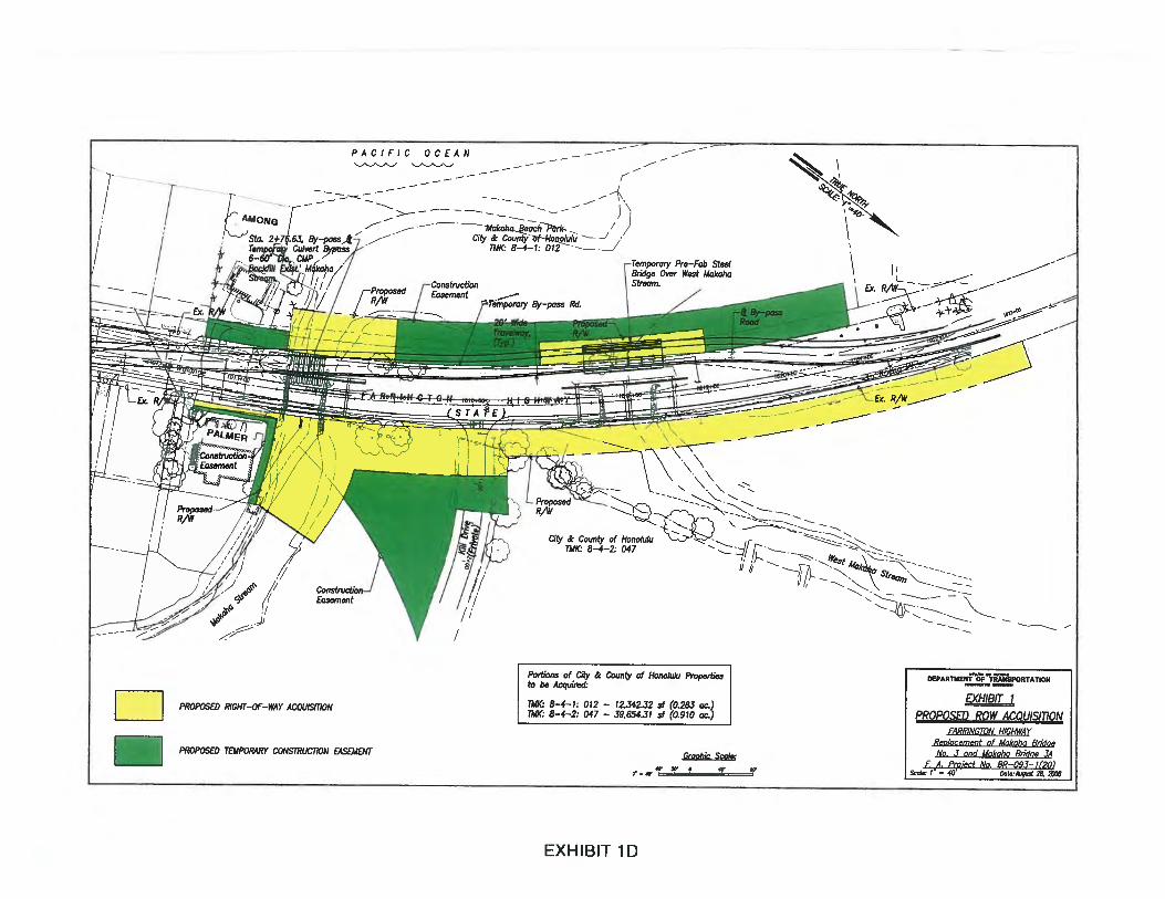
On March 14, 2012, the Commission received written notices from the following property owners statingthat they had withdrawn their permission for the proposed project. Exhibit 1C shows the location of theseowners as well as the Kohl property. Exhibit ID shows DOT’s proposed right-of-way acquisitions andproposed temporary construction easements.
• Moana Kea-Klausmeyer-Among (TMK: (1) 8-4-008:020)• Jason Ellis (TMK: (1) 8-8-018:014)• Robert Palmer (TMK: (1) 8-4-018:014)• Donald Redington(TMK: (1) 8-4-018:123)
On April 3, 2012, the City and County of Honolulu, Department of Planning and Permitting grantedSpecial Management Area (SMA) Permits for the construction of new bridges over Makaha and WestMakaha Streams at Makaha Beach, Oahu.
DESCRIPTION:
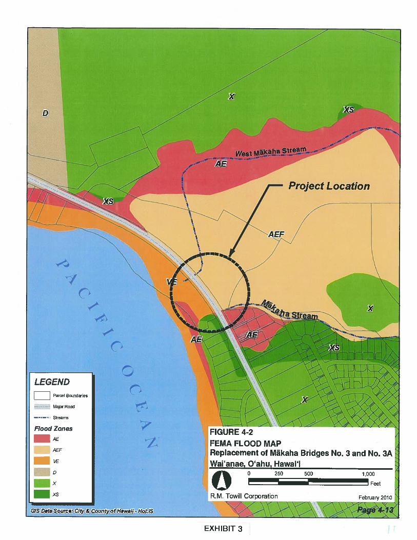
The project site is located in Makaha in Flood Zones AE, AEF, yE, X and XS according to the FederalEmergency Management Agency (FEMA). Zone AE is the flood insurance rate zone that corresponds tothe one-percent annual chance of 100-year floodplain. Zone AEF refers to a floodway area within ZoneAE. The Base Flood Elevation (BFE), derived from detailed hydraulic analysis at the project site is 13feet. Zone VE is the flood insurance rate zone that corresponds to the flood hazard areas inundated by a100-year flood that has additional hazards associated with coastal flood with wave action. The BFE forthis zone is 12 feet. Zones X and XS refer to areas outside the flood limits. See Exhibit 3.
A drainage analysis prepared by FEMA indicated that the existing bridges do not have the hydrauliccapacity to accommodate a 100-year flood event. Should such an event occur, flood waters wouldovertop Farrington Highway. Because the subject property is located within the 100-year floodplain, thenew bridge structures will be designed to accommodate a 100-year flood event. Geotechnical andhydraulic studies have been completed to ensure the structural integrity of the bridges in flooding eventsand were used to prepare the project’s construction plans. The proposed design of the replacementbridges will accommodate the 100-year flood event without increasing flood hazards to adjacentproperties. All work within Zones AE, AEF and VE will be in accordance with the rules and regulationsof the National Flood Insurance Program.
The draft engineering reports and draft plans have been submitted to governmental agencies and utilitycompanies for review and comment. The draft reports and plans cannot be made available to the publicbecause of HDOT policy that draft engineering design documents are not allowed to be released untilafter the project design has been finalized. This provides the public with the correct project design forconstruction that has been reviewed and approved by governmental agencies and the utility companies.
3

Staff Submittal May 16, 2012
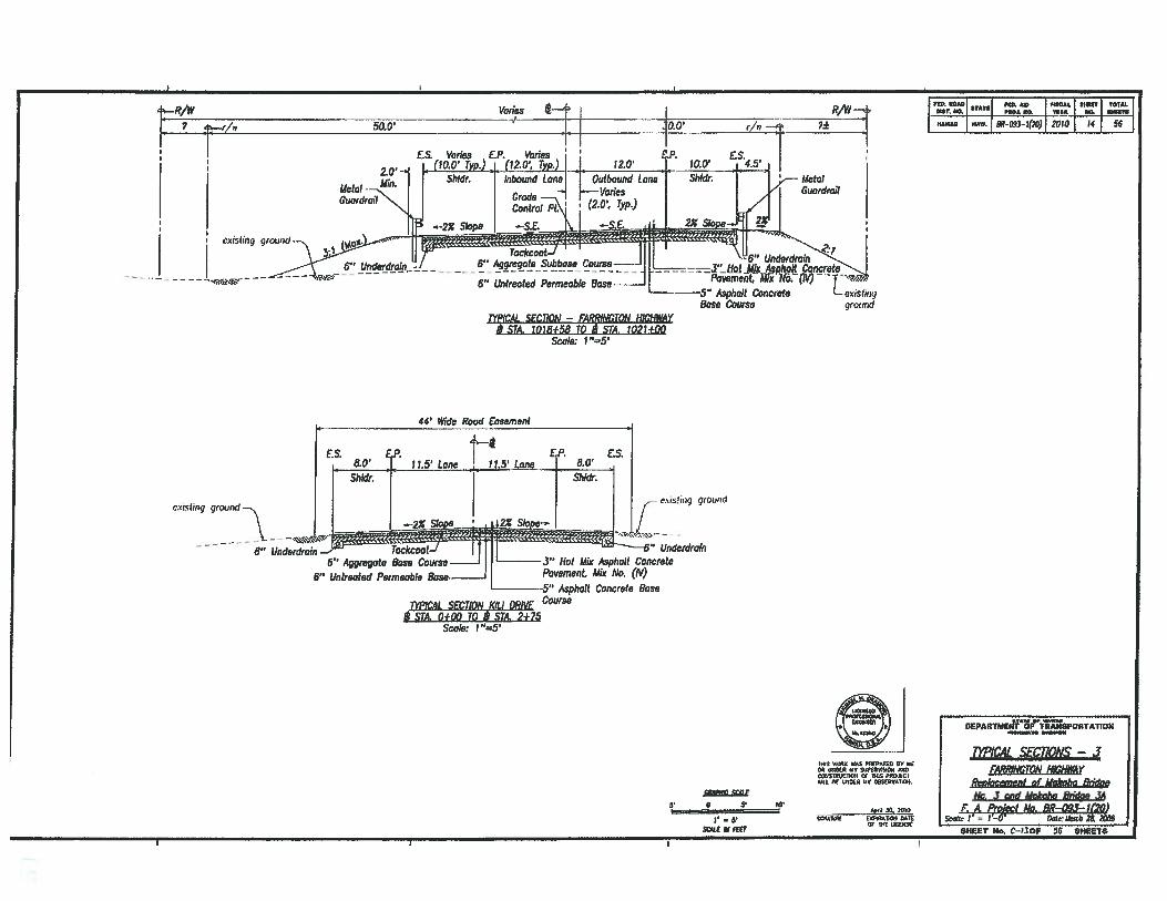
The two existing wooden bridge structures will be replaced with reinforced concrete bridges. Thereplacement bridges will increase the lane widths to 12-foot wide lanes in each direction and 10-foot wideshoulders to accommodate pedestrians and bicyclists. The proposed project will require: construction ofan approximately 1,200-foot long by-pass road on the makai side of the existing highway; demolition ofthe existing wooden bridge structures; construction of temporary bridges; construction of the new bridges,channel slope protection and bridge appurtenances; relocation of utilities; restoration of the site; anddemobilization of construction equipment and materials. The total area involved will be approximately3.8 acres. See Exhibits 4-7.
In order to meet current roadway design requirements, the proposed project will require additional areasbeyond the current right-of-way to accommodate the increased bridge spans and structures necessary forembankment protection, channel widening and guardrail improvements. The proposed wider right-of-way will affect lands on both sides adjacent to the project site. Additionally, the temporary use ofconstruction parcels will be necessary during construction. (See Exhibit 1D.) No residents will bedisplaced by this project.
The proposed project involves excavation in the stream channels to remove soil and excess material anddemolition debris from the concrete aprons, piers, foundations and abutments of the existing bridges.Structures to be constructed within the stream channel include existing slope protection measures(abutment and wing walls) adjacent to and directly under the bridges. To minimize disturbance of thestream bed, the concrete pier foundations of the existing Bridge 3A will be removed by cutting them offat the stream bottom elevation and leaving the footings in place.
Bridge 3 will involve construction of new abutments, wing walls, a center pier, and a concrete aprondirectly under the proposed bridge. To accommodate flows from 100-year storm. events, the new Bridge3 will be a two span structure. In addition to the longer bridge, an approximately 150-foot section ofMakaha Steam will be widened to transition from the existing stream width to the widened channel underthe new bridge structure. Both the upstream and downstream stream banks will be stabilized using rip-rap or similar material to maintain reasonable structural integrity and resistance against storm flows.
The project will also include fill material associated with the temporary by-pass road. Bridge 3A will bespanned by a temporary, pre-fabricated, metal bridge structure including temporary bridge abutments.The by-pass road crossing Makaha Stream for Bridge 3 will be a temporary culvert comprised of six, 60-inch high-density polyethylene (HDPE) pipes. At the vicinity of the Makaha Stream channel crossing,the by-pass road will be constructed using sheet piles and backfilled with appropriate fill material andoverlain with base-course fill and asphalt pavement. All fill material used to construct the by-pass roadwill be removed at the end of the project and the area restored and/or stabilized.
During the construction of the new bridges, stream flow diversion measures will be installed in one-halfof the stream channel at a time using sheet piles, sandbags, pipes, or other appropriate measures. Thepurpose of these measures is to (1) prevent pollutants (silt) from entering the stream should the streamstart flowing during rainfall events and (2) insolate the work area at Bridge 3A to minimize impacts toaquatic organisms in the muliwai during construction. The temporary diversion measures will bedesigned to accommodate high stream flow from storm events. Once the by-pass road is operational, thetwo existing bridges will be demolished. Instream work will be intermittent during the constructionperiod but will be focused on either the makai or mauka areas of the project at one time. Sand bags, sheetpiles, or other appropriate temporary diversion measures will be put in place to isolate the active workareas from the stream. Any material excavated from the stream channel will be stockpiled at a designatedmaterial storage area, or loaded onto trucks for disposal at a county-approved refuse facility.
4

Staff Submittal May 16, 2012
The overall construction schedule is estimated to last about 16 months with intermittent in-streamactivities. However, all in-stream work will be limited to the dry season.
ANALYSIS:
Agency Review Comments:
U.S. Fish and Wildlife Service: recommended that best management practices (BMP5) be implemented tominimize impacts to aquatic resources.
The Department of Health (DOH) Clean Water Branch (CWB): the project is subject to Section 401 andSection 402 National Pollutant Discharge Elimination System (NPDES) permits.
City and County of Honolulu Department of Planning and Permitting:
• The project is located in the Special Management Area (SMA) and is subject to compliance withSMA use permit requirements.
• The applicant must submit construction and grading plans to the City for review and approval.• The project is located within the AE floodway district and the VE coastal high hazard district.
The applicant shall certify that the work will not result in any increase to the regulatory floodelevations.
• Approval of a subdivision application will be required for the additional highway right-of-way tobe obtained from abutting properties.
• If dewatering of excavated material is required before disposal, a stockpiling permit may berequired.
Office of Hawaiian Affairs (OHA) requested clarification on the status of mitigation measures to protectcultural sites and historic properties within the project area and whether the Historic Preservation Divisionhad approved a recovery plan and long-term protection measures for a designated re-internment sitepursuant to applicable provisions of Hawaii Administrative Rules § 13-300.
The Department of Hawaiian Home Lands and the University of Hawaii Environmental Center did notsubmit comments as of the date of preparation of this submittal.
DLNR Review Comments:
Division of Aquatic Resources (DAR): DAR surveyed Makaha Stream in the area of the proposedactivity and the upper reaches in December 2001. At the time of the survey, the stream was dry; however,native o’opu and ‘opae were observed in the middle and upper reaches.
• The proposed replacement bridge is not expected to have any significant impact on the aquaticresources in this area as the construction will be done in phases.
• The temporary stream flow diversion measures will help prevent pollutants from entering thestream and minimize impacts to the aquatic organisms in the muliwai and ocean should thestream start flowing from rainfall events.
• The flow diversion measures should not block the total stream flow during rainfall events toaccommodate the upstream migration of post-larval gobies and allow the passage of larval drift tothe ocean should recruitment spawning occur.
• Mitigative measure should be implemented during the construction of the replacement bridge andretaining walls to minimize the potential for erosion, siltation and pollution of the aquaticenvironment.
5
Staff Submittal May 16, 2012
Engineering: according to the Flood Insurance Rate Map (FIRM), the project site is located in the 100Year Flood Zones VE12, AEF and AE which are regulated by the National Flood Insurance Program(NFIP). The project must comply with the rules and regulations of the NFIP whenever developmentwithin a Special Flood Hazard Area is undertaken.
Historic Preservation (SHPD):
• Approved the applicant’s 2004 Archaeological Monitoring Plan (AMP), the 2007 BurialTreatment Plan, and 2010 Archaeological Data Recovery Plan.
• Requested that a qualified archaeologist conduct on-site monitoring of all ground disturbances inaccordance with the approved AMP.
The Data Recovery Plan focuses on the specific archaeological site, including the iwi (ancestralremains), found on-site as a result of the Archaeological Inventory Survey. The AMP is moregeneral and covers ground disturbing activities throughout the construction project.
State Parks and Forestry and Wildlife: no objections to the project.
Land Division did not submit comments as of the date of preparation of this submittal.
Chapter 343 Environmental Assessment (EA) Compliance Review:
EA Triggers: In accordance with I-IRS §343-5 (a), the applicant’s proposed action triggers an EA becauseState funds will be used for the replacement of Bridges 3 and 3A. On May 23, 2011, the OEQC approvedand published the applicant’s FEA and FONSI for the project.
Staff Review
On April 3, 2012, the City and County of Honolulu, Department of Planning and Permitting grantedSpecial Management Area (SMA) Permits for the project.
HDOT and R.M. Towill are working with property owners Among (Parcel 020) and Palmer (Parcel 014)to obtain the necessary right-of-way (ROW) and temporary construction parcels required for the project.However, the two property owners are opposed to the project because they do not agree with the design ofthe project and believe that HDOT and R.M. Towill are conspiring against them to benefit anotherlandowner (HRT, Parcel 045) at their expense. If HDOT and R.M. Towill are unable to negotiate a ROWand temporary construction agreement with the tvo property owners, HDOT will use eminent domain toacquire the necessary land for the project, although this is not HDOT’s preferred approach.
R.M. Towill and HDOT staff met with the Keith and Juliana Kohis, 84-452 Farrington Highway (Parcel123) to address their concerns about the project’s increased flooding potential at the Kohl’s property.HDOT and R.M. Towill responded to Kohls’ concerns during the SMA permit hearings before the publicand the City Council. On October 3, 2011, R.M. Towill sent the Kohls a 12-page letter addressing theKohis concerns; however, the Kohis still believe that the project will increase the flooding potential totheir property despite the apparent increase of bridge 3’s width, reduction of number of piers, andhydraulic studies. Nevertheless, a No-Rise Certification from the City is still outstanding and is required.See Exhibit 8.
Commission staff also met with the Kohls to discuss their concerns about the project and informed theKohis that stream hydraulics and bridge engineering should be addressed by HDOT engineers and theCity and County Department of Planning and Permitting as part of the SMA permitting process.
6

Staff Submittal May 16, 2012
The applicant will prepare a Best Management Practices (BMP) Plan as part of the applicant’s Section401 Water Quality Certification application which will be filed with the Department of Health CleanWater Branch. The applicant will schedule all in-stream work during the dry season, and the temporarystream flow diversion measures will limit work to one half of the stream at a time to help preventpollutants from entering the stream and accommodate migration of aquatic species during rainfall events.
Staff recommends that the HDOT’s SCAP be approved subject to HDOT acquiring the necessary rights-of way and temporary construction easements required for the project and a No-Rise Certification fromthe City and County of Honolulu Department of Planning and Permitting prior to construction.
RECOMMENDATION:
That the Commission approve a Stream Channel Alteration Permit (SCAP.2621.3) for temporary a bypass road and replacement of Makaha Bridges 3 and 3A in Makaha, Oahu at TMKs: (1) 8-4-1-001:012, 8-4-002:045 and 47, 8-4-008:020 and 8-4-018:014, subject to the following conditions:
1. HDOT must obtain the necessary rights-of-way and construction easements prior toconstruction.
2. HDOT must obtain a No-Rise Certification from the City and County of HonoluluDepartment of Planning and Permitting prior to construction.
3. Standard Conditions in Exhibit 9.
Respectfully submitted,
WILLIAM M. TAMDeputy Director
Exhibits: 1A. Location MaplB. Aerial Photo of Project SiteIC. Map of TMKsID. Proposed ROW Acquisition and Temporary Construction Easement2. Photos of Makaha Stream3. FEMA Flood Map4. Temporary By-Pass Road Plan5. Construction Details6. Existing and Proposed Bridge Elevations7. Final Site Plan8. October 3, 2011, R.M. Towill response to the Kohls9. Standard Stream Channel Alteration Permit Conditions
APPROVED FOR SUBMITTAL:
WILLIAM J. AILA, JR.Chairperson
7

/1/Li.4/ / 1 7
L / 0 /V.’‘c?A.
Project Limits
Bridge No 3A ,..-..
—.
Bridge No. 3 - -
‘S..
- \ ‘ ‘
- i Project Location
O’ahu
I Ia4Li/
GIS Layer Soifrde:H0US
/
Exhibit 1. Project Location & VicinityReplacement of Mäkaha Bridges No. 3 and No. 3AFarrington Highway, Waianae, Oahu, Hawafl
O 0 250 500 1000I______
RIvL TOWILL CORPORATION
EXHIBIT 1A
aExisting Bridge 3
--
Makaha Beach Park
Existing Bridge 3A
4
EXHIBjy J
FIGURE 1 PROJECt SITE WITH AERIAL PHOTOReplacement of Mãkaha Bridges No. 3 and No. 3AFarrington Highway, Walanee, Oahu, Hawaii
j1efltTransportafIon, Highways Division

\<‘S 8-4-2:047 /\\ ‘S City and County of Honolulu}.__—
‘S /S - \/ \\\ 7‘S ‘S Road Easenient 107‘S
S % \ ‘G‘S /
— \ / 8-4-2:045‘S / (HRT Lid)
City and County /8-4-1:012
of Honolulu
k h —(City and County of Honolulu) — — \\
/__a
— Strea,
N 18122
\<19\
:0l8 J\ \8-448o12
------- \8-4-8:017 __—\
016
Figure 1-2 Tax Map Keys (TMKs)Legend Replacement of Mãkaha Bridges No. 3 and No. 3A
Farrington Highway, Wai’anae, Qahu, HawaiiApproximate State Department of Transportation, Highways DivisionLimits of Project
lII I0 100 200 Feet
R.M. TOWILL CORPORATION April 2010
EXHIBIT 1C
rn >< I H
_
— —
_ __
PHOTO 1: BRIDGE 3A -MAUKA SIDE FACING SOUTH WEST
Photos taken 8-1 7-2006
PHOTO 2: BRIDGE 3A - MAUKA SIDE FACING SOUTH
PHOTOS 1 & 2Replacement of Makaha Bridges No. 3 and No. 3AFarrington Highway, Wai’ anae District, 0’ ahu, Hawai’ I
EXHIBIT 2 R. M. TOWILL CORPORATION July 2009

_________
fry____
e
-
PHOTO 4: BRIDGE 3A - MAUKA SIDE FACING NORTH-NORTHWEST
PHOTOS 3 & 4Replacement of Makaha Bridges No. 3 and No. 3A
Photos taken 8-1 7-2006 Farrington Highway, Wai’ anae District, O’ahu, Hawai’ i
PHOTO 3: BRIDGE 3A -MAUKA SIDE FACING NORTH
R. M. TOWILL CORPORATION July 2009

.
—- -; ---
Photo taken 8-1 7-2006
,.5_;:
PHOTO 5: BRIDGE 3 -MAKAI SIDE FACING NORTH-NORTHWEST
PHOTO 5Replacement of Makaha Bridges No. 3 and No. 3AFarrington Highway, Wai’anae District, O’ahu, Hawai’i
R. M. TOWILL CORPORATION July 2009

PHOTO 6: BRIDGE 3 -MAUKA SIDE FACING NORTH-NORTHWEST
PHOTO 6
Photo taken 8-1 7-2006
Replacement of Makaha Bridges No. 3 and No. 3AFarrington Highway, Wai’anae District, O’ahu, Hawai’i
R. M. TOWILL CORPORATION July 2009
—
Photo taken 8-17-2006
PHOTO 7: BRIDGE 3 -MAUKA SIDE FACING NORTHWEST FOLLOWING DRY STREAMBED
PHOTO 7Replacement of Makaha Bridges No. 3 and No. 3AFarrington Highway, Wai’anae District, O’ahu, Hawai’i
R. M. TOWILL CORPORATION July 2009
I
D
Project Location
I
Th
C
or Road
Streams
FloOd ZonesAE
AEF
vE
_____
x
• FfGURE 4-2FEMA FLOOD MAPReplaCemetltot Mãkaha Bridges No. 3 and No. 3A
I Wai’aflae O’ahu Hawai’i
Z.Toiicomorat10n..
EXHIBIT 3

o—Ea?IJJ
ma?
o0
a?-
Ea?o
.
0
xa?
0LIJ
ozC.
(U06
,
2z
I—0—.e
D3E
w
x
F.
Hzw

FED. OAi IT TOTAL
•C tP s NOHSTO
O’ 9utIet4ucture / \. /ons. arce
3? 1727W-7Q 0 /1 1 “A
—102+50,o/s36’U.; ‘/1 1 rLlmltafcrodlng. rR/W000Dne4 \\ s5po
-
H-21 \ roNjSh/C4\ \z’ 9-‘
I
—r \ -r,// 11, \ ci1j - -jill 1
‘• 110 /1,11.1
-
;F
1: , 1300 — — — —
r - .-•——-_
.‘-.::_=:—‘;;;
= Bndg ,
4 4 1403
ii
-
A’
FA / // ‘ - / 7/’ >- - - — 7’
Top of &nb Typ) 450 / 7 IMUkOhO /
//
‘,
A Streom\ ‘1,’ //\..RAvF
&ot p1 &nk yp)\ / I
8 i
f Limit of Gradog.-= / 7’ Canst Parcel— — —-
- I — Est Drain 0jjz /
o Remain Undisturbed) , :‘ -
‘
of G/:i:
//‘ / 4 1:
Shall Grade to AIlw,
-. / / \Drain to Daylight aiiM =.. Coast. Parcel — .Cut Pipe as Re,4uired’ / / ‘\ 1o”” DEPAR1MEN’SPORTATION
/‘/ / / / :/ MAKAHA STREAM
/ / ,.‘
‘ (PADINC AND DRAINAGE PLANFAR/I1NGTQN HIGJIJi4Y
MAKAH1 STREAM GRADING AND DRAINAGE PLAN Rp/acement of Makphc, BridajeScale: I ‘=20’ 1, 3 nd pka8np 34
20’ 0 20’ 40’ PA/gLNo,B—--Q,)1 = 20 o—*——’_ ii Scale: 1 =20 late: May 2010
SHEET No. 114-5 Os 172 SHEETS
EXHIBIT 5

sTA. lOif15Q1OiSTA. 1O1l+7&70
I 0010 FO *0 *100*1 011V TOTAL
________—
swOAOR 1i?_093.4(20) 20W 12 56
STA. lOJjj7&70 TO SM. 1O1J+61.99
r •
SGIL lid OW
a
TIllS 0.000 RIO PTITP0000 WI 00OR 05000 0000.0022 00000007000000 CF 1)1100002000TI’LL 00 LOl000 11110 085tRvAhl00.
.0,0 30. 2010TOW
CF TNT IJC00TT
See S1IL C—18 for Locotkrnof Metal Cuiwdrajl
OEPARTMEt1ZSPOATATIQNI.aNwfl. fl*TN4
m4i stcrious -
FGMrRe.0kocemenl of Makahu &iogeNo. 3 and Ak*oha &id,e .
1A A’o1 M. 8ff-03-- l20Sca 7 0*1. I&C0 2O zooe
6” Aggregate Subbase6” Untreated Permeable Base —
TYPICAL SECTION — FARRINCTON HIGHWAY
gcoud
Scale: 1 “=5’
1WILZ4L SECTION -. FARRINGJON HIGHWAY
Scale: l”=5’
—--5” Asptwit ConcreteBose Course
sosr K. C—fl OF 56 SHEETS

ground
FOD 0000000.00 FlO. .41* I 01000.1 I I TCAL I
(lilT. 1 I 0O3. NO. I 00. 1 HHiOYlJ
lAW. 20W
1. See Sht. C—18 for Location ofMetal Guardrail
__ .r/wJ
30’ 1
Iexsiogground
—I
2% Slnnji,...
flTI -
6” Aggregate Subbase Course .3” Hot Mix Asphalt Concrete
6” Untreated Permeable Base___
I’oi’eme Mix No. (iv)—5” Asphalt Concrete Bass Coarse
TYPICAL SECTION - FARRCTON HIGHWAYSTA. 1014+41.01 TO STA. 1017+31.99
P1W (Varies)
Scale: r—5
Bridge Roilin9(Typ.)
—
50 (Mm.)Pavement
TYPICAL SECTION — BRIDGE 3ASTA. ;077+J1.gg to SM. 1018+58
lvS WUOII WAO PRtP0.00 NY I’0l UO0R liv 0JPW.l5W0 WQOCW01000PQI 01 3l$ pocrcr
or 101000 uv cesr4100co,
30. 1000OG041u10 f3WIR0000I UO11
or nor tocroot
StALS
•_••J— 5•
5GL 0
O5PAR7MIrT1tSPORTAtIONiflTI 8*141011
1WIC.4L SEC17QNS —2FARRINT0N HICIIHI4Y
Replacement of Mak&zu &idaeM. .T and Idakaha &Woe .JA
F: A Th’a/i No. BR-093-7(20)Sccr DlorMJ, 28. 2085Scale: 1 “=5’
SHEE1 tie, C—2OF 56
- F6” Unlreated Permeable
ConcreteBase Course
I TA1 FAD. A FISCAL WSH.AoJ. SD.
_____________
HAWAiI iIAW. 8R-Q93--J(20) 2OO 14 56
e.\IS!Iflg OIJ$IC
Underdrain
3’ 0 5’ 10’
r —
SCIW 91 fEET
oJ
WIWui WAS FAiPHA S “11* HAW.A U SAWRSiScAi .‘AAiCWi3INICTiHA & 1IHSP*G.ICSilL W iISLR UH HAS1SVA11A.
SLiIiIW FAi4iICfl SAILTFL uLaSAl
DEPARTMENT OF TRANSPQRTMION_v4 _‘_
TYPICAL SECTIONS — 3FARiWMTO,’I hWY
Rcthcenient of Makaha 8ddgeli. .3 and &4okaha &,d9e 4* Praleci to. BR-c3—1(2G)
S,’c1e7’ I-O aatcuocI, 2 2X.8
HR/W
__________________ _________
L ‘ -_________
£5. Varies El’. Varies
2.0’(10.0’ Typ.) (12.0’, 7pj
Melol —-..‘‘
Guardrail
flPICAL SECflON — FARIWGION HIGhWAYS STA 1018+56 TO STA. 1021+00
Scale: 1 “=5’
SIA 0+00 10 STA 2+75Scale: 1 “=5’
SHEEI 11*. C—130F & 5HETS

New Concrete Apron (8”thick)View Facing Upstream
New Center Pier —‘
PROPOSED ELEVATION (BRIDGE 3)Replacement of Mãkaha Bridges No. 3 and No. 3AFarrington Highway, Wai’anae, Oahu, HawaiiState Department of Transportation, Highways Division
KM. Towill Corporation August 2010

z 0) Cd.,
-C.
(0 0) g
0 Ui
*
(0 C,
0) 3
ø-nxJ
CDC
D-’
cfl
O oCD
— DI0
CDrn
Drn
° :411 G)
0 zI cIQ 0

EXISTING ELEVATION (BRIDGE 3)Replacement of Mãkaha Bridges No. 3 and No. 3A
Water level observed on 8/17/06 at 11:58 am during site visit.A high tide of 2.0 ft was expected at 12:39 pm.The accumulated material that’s normally under the bridgewas removed to allow for emergency bridge repair due to fire damage.
Farrington Highway, Wai’anae, O’ahu, Hawai’iState Department of Transportation, Highways Division
R.M. Towill Corporation February 2010
EXHIBIT 6
- wood beams
- concretelmortarView Facing Upstream
- mortar & basalt abutment
Accumulated Material
Existing Concrete Apron

:,-
:::z
(
.__rt
o“ r
-
oo
•r
0-.
r:- r r o
‘-r
0“0
0 0 0
17111
I
TIø,1
—•.. C
,
mD
z.-
.
o—
‘(1
)
‘
oD
)D
m)
wI<
=0-i 0
z
0-r
nZ
C)
P.?
Li)

New Concrete Apron (8” thick)
New Center Pier
\
View Facing Upstream
PROPOSED ELEVATION (NEW BRIDGEReplacement of Mãkaha Bridges No. 3 and No. 3AFarrington Highway, Wai’anae, O’ahu, Hawai’iState Department of Transportation, Highways Division
R.M. Towill Corporation February 2010

—w
—a
v
0 .co
m
—0
0w
—%
.Cl
)
•cz
=0
ow
D)
mw
or
0 Z=
0a0 Z
m=
°C
t.)
*
-t
-ft
ftç
ft ft
-..
0-
n‘
ft
4-0 ft
0-
;--t
‘C
tft.
0-#
_0-‘
—.,
oL
s
-tt
—.
.ft (ft _(ft
—ft
-‘n
ftft 9
..ft
ftft
tft
0ftft-
0..
,ft_
ft.
0-,
o.

PACIFIC OCEAN
Mãkaha Beach Park
New Bridge 3A
Adjusted ROW
New Channel Improvements
75’ 375’ 000,
AFTER CONSThUCT1ON
RepIacemt of Mãkaha Bridges No.3 and No. 3AFarringion Highway, WaVnae Oahu, HawapiState Depafl,t of Tra
EXHII3IT 7

2024 N. King Street Pie nnin.gSuite 200 “b l.nglneermg
Honolulu, Hawaii 968193494 Environmental SwvcesTelephone 808 842 1 R. M. TO’Vi.LL CORPO RAT IONT Photogramnietry
Fax 808 842 1937 SurveyngeMail [email protected] S N. C 9 0
Project and Conutruction Management
October 3, 2011
Mr. Keith and Ms. Juliana Kohl86-098 Pokai Bay StreetWai’anae, Hawaii 96792
Dear Mr. and Ms. Kohl:
Subject: SMA Permit File No. 2OIIISMA-38 (WA) & 2OII1MA-39Farrington Highway Replacement of Makaha Bridges No.3 and No 3AWai’anae, Oahu, Hawai’i, FAP No. BR-093-1(20)
On behalf of the State Department of Transportation, Highways Division, thank you for yourletters dated September 2 and 5, 2011, concerning the subject project to the Department ofPlanning and Permitting, City & County of Honolulu. The following has been prepared inresponse to your comments (your comments have been italicized for reference):
1. Letter Dated September 2, 2011
‘We object the proposed design as submitted. Please place this into the file/written record of theSeptember 6, 2011 public hearing on this project”
We acknowledge and are sorry that you object to this important project. A copy of your objectionhas been forwarded to the DOT and we have also placed a copy of your letter into our projectfiles.
“I am requesting the DPP to obtain and make available for copy/review all the survey(s) donesurrounding the design an [SIC] plans for this project I have contacted both Towill and DOT with noresults. To view the original surveys which serve as the basis for the design [SIC] Without theaccompanying surveys, the design/plans cannot be adequately evaluated in their entirety.”
We acknowledge this latest request for information which we have forwarded to the DOT.Unfortunately, we have been advised that the DOT cannot release the survey or constructiondrawings for this project until such time that the plans have been approved by the requiredagencies and parties, and are finalized1.
Although we could not release the above information to you we did furnish you with publiclyavailable information that included a copy of the Final Environmental Assessment (FEA)published by the State Office of Environmental Quality Control (OEQC) on May 23, 2011. Thecontents of the FEA included: (1) why this important project is necessary to be built; (2)theplanned design and activities necessary to accomplish replacement construction of the +70 yearold existing bridges; (3) an evaluation of the project and surrounding site including plannedmitigation measures to reduce or minimize the potential for adverse effects to the environment;and (4) a record of coordination undertaken to date with governmental agencies and thecommunity.
1This is consistent with our prior response to an earlier request by you on September 25, 2005 for therelease of the survey and construction drawings for this project.
EXHIBIT 8

Mr. Keith and Ms. Juliana KohlOctober 3, 2011Page 2 of 12
“In Exhibit I of the EIS submitted, the upstream direction of the Makaha Stream is not correct, andthe plan design shows the stream cuffing beginning just 40 feet upstream from the new proposedBridge 3, such that curve would place the center of Makaha Stream just about running through 64-454 Farrington Hwy, TMK 1-8-4-018-123, and almost onto 84-452 Farrington Hwy, TMK 1-8-4-018-122. This curvature is NOT correct and does not correspond with actual flow during heavy rains.Figure 8-1 shown by Towill is NOT correct flow direction of Makaha Stream currently.”
The FEA does not contain an Exhibit 1. We believe the closest figure you may be referencing isFigure 1-1, Project Location, which is from a topographic map prepared by a licensedprofessional surveyor. Because we do not know if this is the same map being referenced wecannot respond to your comments regarding the curvature or location of the Mãkaha Stream.
We acknowledge your comment regarding Figure 8-1. Figure 8-1, Zoning and SpecialManaiement Area, is a reference map created by a Geographic Information System (GIS) that isdesigned to show the general boundaries for zoning and the Special Management Area (SMA).This type of drawing is therefore useful in depicting general site conditions, such as zoning orother land use boundaries, but it should not be used to understand the detailed flow directions ofstreams or serve as the basis for design.
“Figure 4-2, the FEMA Flood Map, has Makaha Stream in the WRONG position, the stream iscoming down on the northwest side of the island of Zone “X” as depicted in figure 4-2, the streamdoes NOT come from the Nukea and Water Street direction. It does not pass the island zoned ‘X” asshown in Figure 4-2 instead, it flow on the northwest side of the island of Zone “X”.”
“This Map must be veiy outdated or copied without current verification of the Makaha Stream flowcurrently happening (see my photos). The only water flowing from the Nukea street area to MakahaStream proper is coming from the 54’760” culvert drainage pipe which empties the Nukea/liVaterStreet areas roadways, but this flow is minimal compared to the actual Mäkaha Stream. Figure 4-2incorrectly identifies this culvert outflow as the Makaha Stream channel, which is not. The changecould be inpacted [SIC] from upstream development or some drainages system got blocked?????”
“This is verified by the attached photos as well as a simple physical inspection of the area, andespecially obvious during a heavy rain and runoff event Thus I do not agree with the stream“realignment” or depicted direction of the Makaha Stream as put forth by Towill Corp.”
The purpose of Figure 4-2, FEMA Flood Map, is to delineate the types of flood zones thatsurround the project site. The data contained in the figure is the latest available for flood zonesin the City and County of Honolulu. We note your observations regarding flooding at the projectsite but add that Figure 4-2, itself, should not be construed as serving as a detailedtopographical representation of the project site.
“Please see attached photos, which show heavy flow events eating away at the NORTHWEST bankof Makaha Stream on the Kili drive side, owned by HRT which is zoned AEF (flood plain). TheMakaha stream does NOT curve as depicted on Towill’s submissions, but comes down along the KillDrive side of HRT property and is eating away at that northwest embankment, not curvingdramatically toward Nukea Street area as depicted on several Towill submissions, The MakahaStream wants to flow away from 84-454 Farrington Hwy. TMK 1-8-4-018-123, and 84-452 FarringtonHwy, TMK 1-8-4-018-122, but the large silt/rocks deposited by the new runoff out of the forest, asdescribed above, is eating away the embankment and bring a large volume of silt/rocks into thestreambed on the Kili Drive side and slightly diverting the desired path of the Makaha Stream whichis along the Kill Drive side embankment After the interruption from that side, the main flow returns tothe Kili Drive side the last 150 feet before the Bridge 3, as can be seen in the photos. This allcorresponds to the EIS statement contained on page 6-23 at 6.4.2 “Makaha Streams lower

Mr. Keith and Ms. Juliana KohlOctober 3, 2011Page 3 of 12
reaches favor the NorthWest side of the valley” which is exactly the current flow pattern which iscurrently eroding the Kill side embankment for several hundred feet upstream of Bridge 3. The KillDrive side of the stream the last few hundred feet before the Bridge 3 is zoned AEF, or flood plain,so isn’t that exactly what that area is for? For the stream to flow/overflow onto the floodplain insteadof the AE zoned residential side of the Mãkaha Stream? So it is VERY wrong for the design asshown/submitted to try to cuive the streambed back toward the AE zoning, when the current flowfollows the Northwest embankment. If the abnormal runoff described above is eliminated, the streamwill flow along the Kill side embankment mainly and be less danger to the AE zoned side of thestream.”
“The EIS and plans repeatedly states that” The construction of the proposed replacement bridgeswill widen the stream channel to provide sufficient flow capacity to accommodate the 100 year floodevent without overtopping or negatively impacting upstream properties” See page 1-6,”
This comment is similar to and a continuation of the comment above. The proposedimprovements are designed to protect the stream bank from erosion by flood events. Theimprovements are designed to: transition the flow from the existing stream channel to thereplacement bridges; and, allow the 100-year design flood to pass through the replacementbridges. This is possible because portions of the flood hazard area are designated zone AEwhich indicates that the base flood elevations have been determined.
The project’s Final EA states there is sufficient flow capacity by noting on page 1-6 that, “Sincethe publication of the Draft EA, updated information has been obtained and additional analysishas been performed to confirm the flow conditions at the proposed replacement bridges. Theresults of the analysis indicate that the current three span design of bridge 3 needs to beredesigned in order to accommodate the revised 100-year storm flow.”
“Why adding Rip-Rap boulders into existing stream channel in AEF zone, while at same timenarrowing streambed channel from about 95 feet wide at Brdige [SIC] 3 down to only about 45 feet inless than 150 feet upstream????? So this design, with Large Boulders on each side is only 45 feetwide channel 150 feet from Bridge 3, and 95 feet wide only 150 feet later?? If there is a large flow inthe stream, this literally creates a bottleneck, which will increase the flow rate to a maximum rateright at the junction of the property line between 84-450 Farrington and 84-452 Farrington, which isjust about the WORST possible embankment area to endure a maximum flow rate. Yes, as soon asthe channel widens out to 95 feet at the Bridge 3 only 150 feet away, the flow rate will decreaseapproaching the bridge structure (easier on the bridge), and also the level will drop, since a givenvolume of water will be in a wider (and few feet deeper channel). The design submitted will certainlycause a bottleneck of the water volume at the property line at the upstream end of the rip-rap, andadditionally, placing such boulders on the Kill Drive side of the embankment (in AEF zone) actuallyPREVENTS the water from channeling onto the AEF flood plain and will force the water onto theresidential side of the Makaha Stream right before the Bridge 3. Don’t believe it?? Then how comethe proposed height of the Rip-Rap on 84-450 embankment (AE zone side) is about 10 feet, andacross the streambed on the AEF flood plain side Kill Drive side is 11-12 feet or more??”
The dumped rip-rap is required to protect the proposed replacement bridge and streamimprovements from flood damage. The proposed improvements extending upstream of thereplacement bridge matches the existing stream bank. The improvements are designed suchthat there will be no adverse effects to adjacent property. The design increases the width of thestreambed from approximately 40 to approximately 90 feet and increases the bridge span,widens the stream, and minimizes the number of bridge piers to decrease the possibility ofclogging due to debris. The widened stream and increased bridge span will increase theconveyance area through the highway crossing.

Mr. Keith and Ms. Juliana KohlOctober 3, 2011Page 4 of 12
Tax Map Keys (TMKs), 8-4-018: 014, 122 and 123 are currently inundated during large floodevents. The proposed stream bank improvements along TMK 8-4-018:014, is planned to matchexisting conditions in order to allow runoff to continue draining towards the stream. The bankimprovements on the north side of the stream matches the existing conditions and will not bebuilt up to adversely affect flooding conditions to adjacent properties.
“Example: The Ala Wai canal Waikiki side embankment with sidewalk along the Ala Wa isa fewfeet or so HIGHER in height than the Golf Course side embankment. In the event of overflow, therunoff water would tops over the golf course side ofAla Way cannel, while the Waikiki side remainsseveral feet higher and protected by the wall, which is obviously designed to prevent flooding ofWaikiki.”
“So how come the residential AE zone side of Makaha Stream rip-rap would be designed to beLOWER than the AEF zoned Kill Drive side by 2 feet or more?? Thus forcing anything over 10 feetonto residential properties instead of into AEF zone?”
The residential properties are located in a flood hazard area inundated by the 100-year flood.Raising the stream banks, as suggested, could create a condition in which floodwater would beprevented from draining into the stream. This increased potential for flooding would onlyexacerbate the poor drainage conditions at the site. To address this problem the project hasbeen designed to pass the design storm through the bridge structures which will help to alleviatethe flood conditions.
“There are at least t’o responses from DLNR (see attached) contained in the EIS, that informTowill Corp. that they need to correct information regarding the project area and to show that part ofthe project occurs in zone AEF. Also that strict conformance with 44CFR 60.3 (d)(3) provisions mustbe strictly followed, as well as other 44CFR parameters. One of those requirements is that theappilcant must submit a “No-Rise” Certification with the application. I do not see one in thisapplication. It seems like 44CFR may allow for a local permitting officer to make his/her owndetermination of “no-rise” for a minor project, but I don’t think the Bridges 3 and 3A replacement is aminor project, and especially given that it intends to address or alter stream flow direction. Widenchannel, add rip-rap in AEF embankment etc. It is common sense that the volume of water flowingtoward the ocean 100-200 feet upstream from Makaha Bridge will be about the maximum volume,having drained the entire very deep Makaha Valley watershed. So why in the world would ANYdesign reduce a 95 foot wide opening (under the newly proposed bridge) down to a 45 foot wide rip-rap reinforced channel, thus forcing the entire volume through half the size channel which is statedas necessary to prevent overtopping of the Bridge 3?”
A No-Rise Certification will be submitted to the Department of Planning and Permitting. Thedesign will widen the downstream stream bed from approximately 40 feet to approximately 90feet. The shape of the flow will be changed from the narrow existing stream channel to asignificantly widened channel made possible by the downstream bridge improvements. Incontrast to the statement above the proposed design will not: “...reduce a 95 foot wide opening(under the newly proposed bridge) down to a 45 foot wide np-rap reinforced channel”.
“Towill repeatedly states in the ElS and plans that” The construction of the proposed replacementbridges will widen the stream channel to provide sufficient flow capacity to accommodate the 100year flood event without overtopping or negatively impacting upstream properties” (See page 8-14),and “without overtopping or negatively impacting upstream properties” (see 1-6). Again, on page 4-11 “The proposed design would widen the stream channels to accommodate the 100 year floodevent without increasing flood hazards to adjacent properties” How can the channel only half aswide 150 feet upstream accommodate the same 100 year flow as the 95 foot wide bridge openingwhich is being widened from 60 feet to 95 feet to accommodate the 100 year flood. I.e. how can a 45

Mr. Keith and Ms. Juliana KohlOctober 3, 2011Page 5 of 12
foot opening accommodate what a 60 foot opening could not accommodate? Towill mantra repeatedagain on page 4-12!!”
“But who made such a determination? Towill by simply saying so?? There is no “No-RiseCertification submitted, and yet this plan wants to “realign the Makaha Stream channel” “widen”the stream channel” (while actually NARROWING the channel from 95 feet wide to only 45 feetwide in less than a 150 section, which section has the same flow volume unchanged during the 150foot reduction), and “excavate and add rip-rap” in an AEF zone. So Towill states as applicant thatthere will “no negative impact on upstream properties”, namely and especially 84-450 and 84-452Farrington, but besides their own statement, there is no data or no adherence to 44CFRrequirements, which DLNR engineers at least twice specifically noted need to be included, andaddressed, not just glossed over with a self solving applicant statement of “no impact” and no“overtopping of upstream properties” .... I beg to differ, that the proposed plans and omissions may infact cause overtopping onto and erosion into 84-450 and 84-452 properties or embankments, whileactually protecting the AEF embankment without any residences! The water speed will be greater atthe bottleneck of the rip-rap, and deteriorate the embankment of 84-452 because of the narrowing ofthe stream channel.”
“Towill states on page 1-5 “Bridge 3 cannot accommodate the 100 year flood now” ... thus they wantto widen the bridge/channel.. .so if the bridge opening needs to be 95 feet wide to accommodate the100 year flow, then why would they artificially make the stream channel only 45 feet wide 150 feetupstream?? Additionally, the streambed is 2-3 lower in elevation at the Bridge allowing for muchmore water volume than 150 feet away upstream, which is not only haff as wide, but the elevation is2-3 feet higher. (simply don’t understand the reason to reinforce the REDUCED streambed widthwith rip-rap boulders, and make the water go faster and higher right at the 84-450 and 84-452property line. This will cause a maximum water speed and maximum RISE in water height right atThat point. 44CFR requires that “no rise” is allowable. In this plan it almost seems like the designcould not be worse for the 84-450 and 84-452 Farrington residential properties.”
“or [SIC] Why would the Makaha Stream be “realigned” toward The residential side, when it is actuallyflowing and eroding the Kill Drive side on the channel all the way up several hundred feet from theBilge [SIC] 3 in the Northwest embankment? (see photos)”
The project design was determined based on performing hydrologic and hydraulic analyses forthe design of the replacement bridges and stream improvements. The proposed improvementstransition from a widened stream channel at the downstream end of Bridge No. 3, to the existingstream channel approximately 140 feet upstream of the bridge. There is no narrowing of anysection of the existing stream that would lead to an increase of water surface elevation.
Because the existing stream above the project site does not have the capacity to contain the100-year flow, during a large storm event stormflows will overtop the banks of the MãkahaStream and extend into the overbank area. This existing condition requires that the streambanks be designed to protect the replacement bridge structure while causing no increase in theexisting flood elevation. As indicated above, the stream alignment ties into the existing streambank upstream of the project.
“Figure 1-2 line showing “top of embankment” on kill Drive side of Makaha stream is not correct,does not show inflow of water and eaten away embankment across from 84-452 Farrington Hwy,TMK 1-8-4-018-122 and 413-C as described newly appearing large volume flow, maybe frommakaha Stream West.”
We do not know the source or basis for the assertion above. However, the existing conditionsused in performing the hydraulic analysis were obtained from a topographic survey after the

Mr. Keith and Ms. Juliana KohlOctober 3, 2011Page 6 of 12
December 2008 flood event. The majority of the stream flow originates from above the sitethrough the Mãkaha Resort and Golf Club.
“No rip-rap should be placed on AEF side of stream and especially rip-rap which has a heightHIGHER than the residential side of Makaha Stream approaching Bridge 3, simply leave it alone.and [SIC] to just add the Bridge 3 apron and abutment protections at the bridge itself, and let thestream determine the channel to get to the bridge. Besides, with the amount of silt and pebbles, andeven larger stones and rocks that move downstream during heavy flow events, any rip-rap may soonbe covered as if it wasn’t there, EXCEPT for rip [SIC] rip-rap on the Kill Drive side acting to divert thestream back toward the AE side instead of letting it correctly go to the AEF floodplain. If any rip-rapis allowed in the approach to the Bridge 3, it should be ONLY on the residential side of theembankment and should be made consistently HIGHER in height on the residential side, than on theKill Drive AEF flood plain side.”
This comment appears to be similar to the one above at the bottom half of Page 3. Please referto our previous response.
“In short, we strongly object this current design - This design will MANUALLY create an artificialwater flow bottleneck just before (about 150 feet upstream) the heavy volume runoff water reachesMakaha Bridge 3. Obviously the main aim of this design is to protect the bridge, with slower flow andwider channel created within the last 150 feet approaching Bridge 3. This is being proposed to thedetriment of the upstream adjacent residential properties - creating a bottleneck - which may causeovertopping of those properties embankments.”
Although we acknowledge your objection, we wish to clarify that this project does not result inthe creation of a bottleneck; the bottleneck you refer to is an existing condition that the proposedproject will help to relieve.
“I also wish to herein note that in the past year or so, during heavy rains, it appears that anabnormally large volume of runoff, even up to about half the flow volume of the Makaha Stream itself,has been pouring into the Makaha Stream diredily across from 84-452 Farrington Hwy, TMK 1-8-4-018-122, and 84-454 Farrington Hwy, TMK 1-8-4-018-123, Le. the Kill drive side of Makaha Stream.This newly appearing inflow which was not seen in years past, has veiy significantly increased thevolume of Makaha Stream just before approaching the bridge. That water coming into MakahaStream has been completely muddy brown, and I suspect has something to do with the bulldozing ofthe large project area which looks like a new housing development area, up Kill Drive on the right afew hundred yards from Farrington Hwy. 1 believe that may be TMK 1-8-4-002-064, a 13 acre parcel,I do not know that project name. However, the amount of water coming essentially out of the forestinto Makaha Stream during/after heavy rain from the Kill Drive side about 200+ feet Mauka of theBridge 3, is veiy abnormal, and only seen the past year or so, not previously, hence I believe that theMakaha Stream West (the one that is supposed to not connect with the Makaha Stream andsupposed to run under Kill Drive and empty under Bridge 3A) has been actually diverted or filled insomehow, such that BOTH streams are now merging just before Makaha Bridge 3. I think theCity/State should determine what has occurred and going on and where this large volume of water iscoming from, I don’t think Towill or DOT is aware of it. Even during the heaviest rains and when theMakaha Stream is flowing all the way to the ocean, there is no flow ouiard toward the ocean of anyrunoff under Makaha Bridge 3A from Makaha Stream West. This could be because Makaha StreamWest has been altered or diverted under or around upstream development projects, or maybe someupstream drainage system got blocked, such that all runoff is actually going out in Mkaha [SIC]Stream only.
We acknowledge your observations concerning runoff from the area of the project site. We addthat a principal objective of this project is to improve the capacity of the bridges to accommodate

Mr. Keith and Ms. Juliana KohlOctober 3, 2011Page 7 of 12
the 1 00-year flood event; a capacity level which the existing bridges do not now meet. In order toaccomplish this objective geotechnical and hydraulic studies were undertaken to ensure thestructural integrity of the bridges and to improve the handling of storm flows from the project site.
“if the drain-pipe on 84-450 property is replaced, should it have a one-way valve function such thathigh water cannot back up through the pipe to the residential properties, yet allow for draining.”
The suggestion for the installation of a one-way valve is noted. However, due to maintenanceand liability issues the project will include the installation of in-kind drainage features.
“Is there a web sit [SIC] we where we can access updated design for this project??Is Land Right of Way purchase completed yet?Dust Screen end at 84-450 property line? Need Tall dust screen to prevent debris go to 84-452property and stream bed too.”
A website specific to this project has not been and is not anticipated to be required.
The purchase of easements or rights-of-way has not yet been completed.
The suggestion for use of a tall dust screen is noted and will be considered for use by theconstruction contractor who will be responsible for the installation of mitigation measures suchas dust screens.
2. Letter Dated September 6, 2011
“This is additional written testimony/comments/questions concerning the Makaha Bridges 3 and 3Aproject, in addition to that submitted September 2, 2011 at DPP. I do apologize for the somewhatdisjointed order/clarify of my comments/questions etc, I have not had enough time since the C&Cnotice came out to read eveiything thoroughly but nevertheless am expressing mytestimony/concerns here as best as possible.”
This comment is acknowledged.
“Please be advised that I probably should clarify my previous stated “opposed to project” statement Iam not opposed to the rebuilding of the Makaha bridges into modern, stronger, and longer spanbridges, what I am more specifically opposed to is the current Makaha Stream Channel Plan” andthe” Makaha Stream Grading and Drainage Plan” as designed currently, and the Makaha Stream“realignment” notion, which these current plans I believe will increase the possibility of overtoppingthe embankments of the adjacent residential properties, especially 84-450 and 84-452 FerringtonHwy.”
This comment is acknowledged.
“This project is called the “Makaha Bridges 3 and 3A Replacement project” but realigning theMakaha Streams de facto existing flow direction, and adding encumbrances onto the AEF zone(flood plain) embankment that actually NARROW the stream bed, not widen it as repeatedly stated,are a whole different notion/ball game. In previous contacts with Towill they have repeatedly told methat this is a “bridge” project, not a flood control or stream project. Well, then how come this “streamrealignment” and channel widening (actually narrowing), are incorporated without adequate waterflow analysis/data, other than Towill stating “no negative impact or overtopping of upstream adjacentproperties”?”

Mr. Keith and Ms. Juliana KohlOctober 3, 2011Page 8 of 12
The proposed project including the bridges and drainage facilities does not involve a “narrowing’1of the stream as the flows will be required to meet the existing regulations of the StateDepartment of Transportation and City & County of Honolulu.
Please also refer to the responses to your previous letter dated September 2, 2011, above,concerning “narrowing” of the stream.
“I see a bottleneck in The Makaha Stream about 150 feet upstream of the Bridge 3 being proposed byTowill, a MAN MADE bottleneck, and on top of that a design to curie the actual existing DE FACTOflow direction of the Makaha Stream, without any real explanation as to WHY such “realignement[SIC] is necessaty or desirable andwhat [SIC] is the PURPOSE of realignment of the MkahaStream channel?”
Please refer to the responses to your previous letter dated September 2, 2011, above.
“The current stream realignment and channel design, constructed in the AEF Zone (flood plain) doesnot have any engineering data to back it up, based on any hydrological analysis, or water height flowdata whatsoever. The EIS states over and over again that there will be no negative impact toupstream properties, without any scientific sunley data or flow/depth of flow analysis to certul, thatstatement.”
This reference to a lack of engineering data to substantiate the proposed stream realignmentand channel design in the project’s EA (not EIS) appears to be in error. The purpose of theproject’s Final EA is to meet the requirements of Hawaii Revised Statutes, Chapter 343,principally involving the public’s right to disclosure on a project’s potential for adverseenvironmental effects, the alternatives that were considered, and the mitigation measures thatare proposed to address the possibility of adverse effects, among other requirements. Thereview of the physical design of the project is handled by governmental agencies that include theState DOT, City Department of Planning and Permitting, Army Corps of Engineers, and otheragencies, organizations, and utility companies, e.g., such as the Board of Water Supply,Hawaiian Electric Company, and others.
With further regard to the design of the project, including the supporting documentation tosubstantiate the design, the following minimum analyses will be prepared: hydrologic andhydraulic analysis in accordance with the State of Hawaii, Department of Transportation, DesignCriteria for Highway Drainage, 10/1/10; and the design of bridge and stream improvements willbe in prepared in accordance with the appropriate Federal Highway Administration, HydraulicEngineering Circulars.
“As previously stated and submitted, 44CFR requires that a “no - rise” Certification should beattached to this application, instead of blanket statements by the applicant of “no negative impact”.Towilljust keeps repeating “no negative impact” and “no overtopping” of upstream adjacentproperties, without any data, or certification. 44CFR allows for the local permit reviewer (i.e. in thisinstance William Ammons/C&C) to certify the “no - rise” certification or “no negative impact”.”
“But as I see it, in response to DLNR’s notation to Towill that they must comply with 44CFR60.3(d)(3)requirements when working in an AEF Zone (i.e. the Kili Drive side of the Makaha Stream), Towillsimply stated back to DLNR that the application would be properly submitted through the C&C ofHonolulu permitting process does this mean that Towill hoped this narrowing of the channel from95 feet down to 45 feet within only 150 feet distance creating a bottleneck in the streambed wouldpass William Ammons/C&C review and thus become essentially “certified” by C&C (which does notmeet 44CFR requirement), such that Towill would then maintain everything was approved by the

Mr. Keith and Ms. Juliana KohlOctober 3, 2011Page 9 of 12
C&C Honolulu? 44CFR allows for a city planner to certify “no-rise” for veiy minor projects orconstruction, but does Makaha Stream REALIGNMENT and CHANNEL WIDENING and RIP-PAPon the AEF zone (flood plain) embankment qualify as a “minor” project in light of the statement thatthis area is “prone to flooding” as stated by the applicant on page 8-14? Where is Towills “no-rise”study, data, or certification about the AEF zone (flood plain) embankment reinforcement plan? Theycan’t just throw it in and hope it gets past C&C and thus they are off the hook for the certification, orwas that what Towill is tiying to do? I don’t see anything to support their repeated “no negativeimpact” and “no overtopping upstream” statements, but the current “Makaha Stream Channel Plan”and the “Makaha Stream Grading and Drainage Plan” themselves show a self-evident bottleneckalmost designed specifically to do just that, i.e. cause constricted flow that could lead to overtoppingat the narrowest juncture.”
As noted, a “no-rise” certification application for this project will be submitted to the Departmentof Planning and Permitting.
The design of the channel is based on the DOT, Design Criteria for Highway Drainage, 10/1/1 0.
Page 8-14, at 8.3.3 describes the requirement for a “specific finding” regarding work in AEF Zone,not an applicants blanket statements, which statements seem to conflict with the actual proposeddesign utilizing a narrowed channel 150 feet upstream.”
The specific finding that is referenced is stated as: All Federal or Federally-aided construction ofbuildings, etc., which encroach upon or affect the base floodplain, requires an assessment offloodplain hazards and a specific finding for significant encroachments is required in the finalenvironmental document.
An engineering assessment of the floodplain hazard indicated that the bridges have poorhydraulic capacity and that a widening of the stream channel to provide sufficient flow capacitywould be necessary. The “encroachment” would consist of widening the stream channel (andincreasing the bridge openings) to accommodate the 100-year flood event without overtoppingor negatively impacting upstream properties. The “finding” of the act of widening the bridgeopening was that:
“The proposed project occurs within an area prone to flooding, however the planningimprovements is anticipated to result in enhancement of existing flood conditions at the projectsite. [And furthermore thati The proposed project will be designed in compliance with therequirements of AASHTO, FHWA, H DOT, City and County of Honolulu and the Department ofthe Army, Corps of Engineers.”
These findings and the proposed project design do not conflict with one another. We also wishto clarify that this project will not involve the use of, “. . .a narrowed channel 150 feet upstream”,as noted in the comment above.
“Page 8-14 mentions AASHTO, FHWA, HDOT, C&C Honolulu, and Army Corps of Engineersrequirements Do all these approve of bottle necking the stream with reinforced rip-rapembankments ADDED to the streambed, which restrict heavy flow to an opening only half as widejust 150 feet upstream from Bridge 3?”
“The channel design is OBVIOUSLY made to have water speed and depth LESS at the bridgeopening, while only 150 feet upstream, the speed/flow of a heavy runoff will be MUCH greater,forced through a 45 foot wide bottleneck (and direction altered) created by Towilil! The purpose I

Mr. Keith and Ms. Juliana KohlOctober 3, 2011Page 10 of 12
believe is to minimize water impact/force/speed on the Makaha Bridge 3 and ifs abutments,apparently at the expense of adjacent properties 84-450 and 84-452 Farrington.
Construction documents for the proposed improvements are being routed to the appropriategovernment agencies for review and approval. The proposed improvements are designed toavoid as much as practicable any negative effects to adjacent properties.
The proposed improvements will reheve some of the existing bottleneck conditions of the streamby widening the stream bed.
Page 12 and 1-3 drawings are not even consistent as to the location and direction of the MakahaStream. Yet these are dated Februaiy 2010 and April 2010. Why the change?”
The two figures cited above reference the same project site but serve different purposes: Figure1-1, Proiect Location, is based on the topographic base map for this project and is intended toshow the general location of the project site in relation to its immediate surroundings.
Figure 1-2, Tax Map Keys (TMKs), is based on a program called Win2Data that shows onlyparcel boundaries, the stream centerline and the shoreline. The orientation of this map is alsodifferent from Figure 1-1, as noted by the north arrow. In short, these are two different mapsshowing different themes (subjects) that serve different purposes.
“There is the “Makaha Stream Channel Plan” and the “Makaha Stream Grading and Drainage Planthis indicates that major work is to be done in the Makaha Stream channel, not minor work
Actually the cost of this work is minimal compared to the Bridge structure, however, the possiblenegative impact on adjacent residential properties by the proposal as it stands can be greatlydamaging, and will cause overtopping right at the bottleneck in a heavy runoff event. And to say “nonegative impact” and “no overtopping” is simply wrong and irresponsible, if not intentionally so. 1even wrote Towill a Certified letter at least two years ago warning of the danger of their proposed rip-rap design, and how it would divert water onto adjacent residential properties, right at the SAMEpoint at the property line of 84-450 and 84-452 Farrington, right where they intend to end the rip-rap.Towill did not reply, and I see the design ignores that concern experessed [SIC] two years ago!Towill is only concerned about slowing the flow/depthspeed [SIC] of heavy runoff water immediatelybefore it hits the Bridge 3, so that Towill’s Bridge 3 “still stands” no matter what. That notion is fine,but can’t be done at the expense of endangering upstream properties to higher water levers [SIC] bymanipulating the Makaha Stream channeL”
We do not agree that this project will have a negative impact on adjacent residential properties.On the contrary, the proposed replacement bridge will be designed to pass up to the 100-yearflood through the bridge structure without increasing the flood water elevation, a situation that isnot possible today. By allowing the flow to pass under the highway as opposed to the currentcondition in which the flood overtops the highway, the flood water elevation will decreaseresulting in a lower potential impact to adjacent residential properties.
We also do not agree concerning the comment involving the proposed use of rip-rap boulders.Please refer to our response cited previously on the bottom half of page 3 of this letter.
“The Makaha Stream channel can be widened much more than h the current submitted design plansin the AEF zone (flood plain) Kill Drive side embankment to accommodate high/heavy runoff better,so why in the world RESTRICT the width of the channel on the AEF zone (flood plain) sidedramatically?”

Mr. Keith arid Ms. Juliana KohlOctober 3, 2011Page 11 ofl2
“What is the REASON for “REALIGNMENT” of Makaha Stream?? And is the realignment proposedan “IMPROVEMENT? And what evidence presented that the realignment is an improvement? (anconstricting/narrowing the channel into about 3/5 width within a vely short distance, about 150 feet)Same questions ought to be answered.”
“Probably the cheapest apart of this entire Bridge 3 construction plan is the channel widening andembankment rip-rap, however the current design is misguided. Itwould [SIC) be best to provideSUFFiCIENT and EFFECTIVE embankment protection on the residential zone side of Mãkahastream, but at least DO NOT pile up bunch of boulders on the AEF (conseivation) zone, or floodplain side of Makaha stream, and making the stream NARROW at the end of the rip-rap. The currentdesign is adding an impediment to the current flow channel of the stream, yet is not sufficient to“realign” the stream channeL No rip-rap at all on the AEF side would be a better design, and allowheavy flow to enter AEF side away from residential side of the stream.”
We disagree that the project design constitutes “an impediment to the current flow channel ofthe stream.” The proposed improvements widen the stream, and do not narrow or constrict theflow. The centerline of the stream is being realigned to transition the existing stream to thewidened proposed bridge structure. The proposed stream bank improvements necessary for thebridge replacement are protected from flood damage. The proposed stream bank improvementsare also designed to tie into the existing stream bank at an elevation that will not restrict flowupstream of the project.
“I am also concerned about the duration of the proposed construction, as I’m sure many others are.”
“However, maybe my concern is not exactly the same reason. I feel the contractors must understandthat during heavy rain/runoff events, the Makaha Stream can have a ve,y significant volume of water,such that I would not want to see some bypass pipes installed that were unable to handle the volumeduring construction, thus causing a backup of water (pooling) upstream, as well as damaging thework so far accomplished. From that point of view, along with the fact that a longer duration meansmore dust, traffic etc problems, there would be much less chance of a heavy rain event from Marchthrough November of any year, thus if the work could be accomplished during 9 months instead of12-15, would lessen chance of significant damages from a large rainfall event.”
The DOT shares this concern involving the duration of construction of approximately 16 to 18months. This estimate was reduced from earlier projections of as much as 24 months. The DOTunderstands this is an important transportation corridor in Mãkaha and plans to maintain theperiod of construction to as short a time as possible by doing the work on both bridges at thesame time instead of working on only one bridge at a time; and possibly using extended workhours.
“Attached are just some of the exhThits pertaining to many of the above concerns, more arecontaining in the plans and EIS themselves.”
“Again, we do not object specifically to the rebuilding of the Makaha Bridges 3 and 3A. We do objectto the current “Makaha Stream Grading and Drainage Plan” and the “Makaha Stream Channel Plan”submitted designs, with the concerns and testimony submitted herein and also previously submittedon September 2, 2011. The plans may in fact negatively affect upstream residential properties andcause overtopping upstream as noted, despite Towill’s repeated unsupported statements otherwise.Towill’s sole aim is to protect the Bridge 3 from water speed/depth/force by widening the channelright before the Bridge 3, which they ti’y to accomplish by the dramatic widening beginning about 150feet upstream from the Bridge 3, from 45 feet wide to 95 feet wide. The EIS states the Bridge 3needs to be about 90 feet wide to handle the 100 year flood event without overtopping. The openingunder the Bridge is thus twice as wide and deeper by 2-3 feet than at the mauka end of the proposed

Mr. Keith and Ms. Juliana KohlOctober 3, 2011Page 12 of 12
np-rap, so where would the constricted flow go when constricted to about 45 feet wide 150 feetmauka of the bridge 3? This constricting effect does not just apply to the 100 year flow event, butlesser events, that could be threshold 100 year runoff but would possibly overtop because of the 45foot wide created constriction.”
We acknowledge your objections and have attempted to respond in a constructive manner toyour numerous concerns. Your objections and concerns, and our responses, have beendocumented in this reply and will be forwarded to the Department of Planning and Permitting.
We appreciate this opportunity to respond. Any further written comments may be directed to theundersigned.
Sincerely,
Brian TakedaPlanning Project Coordinator
BTIMOcc: Mr. Henry Kennedy, P.E., State Department of Transportation, Highways Division
Mr. William Ammons, Department of Planning and Permitting, City & County of Honolulu

STANDARD STREAM CHANNEL ALTERATION PER.M.IT CONDITIONS(Revised 9/19/07)
The permit application and staff submittal approved by the Commission at its meeting on May 16,2012, shall be incorporated herein by reference.
2. The applicant shall comply with all other applicable statutes, ordinances, and regulations of theFederal, State and county governments.
3. The applicant, his successors, assigns, officers, employees, contractors, agents, andrepresentatives, shall indemnify, defend, and hold the State of Hawaii harmless from and againstany claim or demand for loss, liability, or damage including claims for property damage, personalinjury, or death arising out of any act or omission of the applicant or his successors, assigns,officers, employees, contractors, and agents under this permit or related to the granting of thispermit.
4 The applicant shall notify the Commission, by letter, of the actual dates of project initiation andcompletion. The applicant shall submit a set of as-built plans and photos of the completed workto the Commission upon completion of this project. This permit may be revoked if work is notstarted within six (6) months after the date of approval or if work is suspended or abandoned forsix (6) months, unless otherwise specified. The proposed work under this stream channelalteration permit shall be completed within two (2) years from the date of permit approval, unlessotherwise specified. The permit may be extended by the Commission upon showing of goodcause and good-faith performance. A request to extend the permit shall be submitted to theCommission no later than three (3) months prior to the date the permit expires. If thecommencement or completion date is not met, the Commission may revoke the permit aftergiving the permittee notice of the proposed action and an opportunity to be heard.
5. Before proceeding with any work authorized by the Commission, the applicant shall submit oneset of construction plans and specifications to determine consistency with the conditions of thepermit and the declarations set forth in the permit application.
6. The applicant shall develop site-specific, construction best management practices (BMPs) that aredesigned, implemented, operated, and maintained by the applicant and its contractor to properlyisolate and confine construction activities and to contain and prevent any potential pollutant(s)discharges from adversely impacting state waters. BMPs shall control erosion and dust duringconstruction and schedule construction activities during periods of low stream flow.
7. The applicant shall protect and preserve the natural character of the stream bank and stream bedto the greatest extent possible. The applicant shall plant or cover lands denuded of vegetation asquickly as possible to prevent erosion and use native plant species common to riparianenvironments to improve the habitat quality of the stream environment.
8. In the event that subsurface cultural remains such as artifacts, burials or deposits of shells orcharcoal are encountered during excavation work, the applicant shall stop work in the area of thefind and contact the Department’s Historic Preservation Division immediately. Work maycommence only after written concurrence by the State Historic Preservation Division.
EXHIBIT 9