
June 2011 Local raw materials for production of fish feed for

1000 TPD CO2 CAPTURE PLANT FEED STUDY
DEVON JACKFISH 1 OILSANDS OPERATIONS
Front End Engineering Design Study
Submitted by
HTC Purenergy Inc.
November 2011
Submitted to
Climate Change and Emissions
Management Corporation (CCEMC)
““PPrroovviiddiinngg GGlloobbaall SSoolluuttiioonnss
ffoorr CCOO22 CCaappttuurree aanndd SSttoorraaggee””

©2011 HTC Purenergy Inc. All rights reserved. HTC Purenergy Inc. Confidential. Contains information that is confidential and proprietary to HTC Purenergy Inc. (“HTC”) and may not to be used, reproduced, or disclosed in any format without HTC’s prior written permission. This document is prepared by HTC and DEVON ENERGY exclusively for the CCEMC and is not to be used in conjunction with any other project.
1000 TPD CO2 CAPTURE PLANT FEED STUDY
DEVON JACKFISH 1 OILSANDS OPERATIONS
FEED STUDY REPORT DEV-JA-03-001-1 (R1)
HTC PURENERGY PROPRIETARY AND CONFIDENTIAL Page
1 (19)
1000 TPD CO2 CAPTURE PLANT FEED STUDY
DEVON JACKFISH 1 OILSANDS OPERATIONS
Front End Engineering and Design Study
1 21-NOV-2011 FEED Report Issued for Publication Salim Kadiwala/ Pawan Kundra
Allan Hart/ Mohamed Elgarni
Ahmed Aboudheir
0 29-SEPT-2011 FEED Report to CCEMC/Devon Review Salim Kadiwala Allan Hart Ahmed Aboudheir
REV. DATE DD-MMM-YYYY
STATUS PREPARED BY REVIEWED BY APPROVED BY
DOCUMENT REVISIONS
1000 TPD CO2 CAPTURE PLANT FEED STUDY
DEVON JACKFISH 1 OILSANDS OPERATIONS
FEED STUDY REPORT DEV-JA-03-001-1 (R1)
HTC PURENERGY PROPRIETARY AND CONFIDENTIAL Page
2 (19)
Contents
EXECUTIVE SUMMARY 3
1 INTRODUCTION 5
2 DESIGN BASIS 7
3 PROCESS DESIGN 9
3.1 BATTERY LIMITS AND BLOCK FLOW DIAGRAM 9
3.2 CO2 CAPTURE PLANT PROCESS DESCRIPTION 9
3.3 KEY PERFORMANCE INDICATORS 11
3.4 UTILITY SUMMARY 14
3.5 PROCESS OPTIMIZATION 14
4 CAPITAL COST ESTIMATE 16
5 ENGINEERING, FABRICATION & SITE INSTALLATION SCHEDULE 17
6 RECOMMENDATIONS 18
7 CONCLUSIONS 19
1000 TPD CO2 CAPTURE PLANT FEED STUDY
DEVON JACKFISH 1 OILSANDS OPERATIONS
FEED STUDY REPORT DEV-JA-03-001-1 (R1)
HTC PURENERGY PROPRIETARY AND CONFIDENTIAL Page
3 (19)
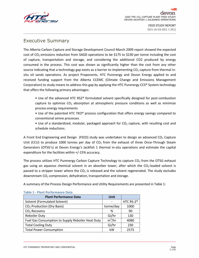
Executive Summary
The Alberta Carbon Capture and Storage Development Council March 2009 report showed the expected
cost of CO2 emissions reduction from SAGD operations to be $175 to $230 per tonne including the cost
of capture, transportation and storage, and considering the additional CO2 produced by energy
consumed in the process. This cost was shown as significantly higher than the cost from any other
source indicating that a technology gap exists as a barrier to implementing CO2 capture from thermal in-
situ oil sands operations. As project Proponents, HTC Purenergy and Devon Energy applied to and
received funding support from the Alberta CCEMC (Climate Change and Emissions Management
Corporation) to study means to address this gap by applying the HTC Purenergy CCS® System technology
that offers the following primary advantages:
• Use of the advanced HTC RS2® formulated solvent specifically designed for post-combustion
capture to optimize CO2 absorption at atmospheric pressure conditions as well as minimize
process energy requirements
• Use of the patented HTC TKO® process configuration that offers energy savings compared to
conventional amine processes
• Use of a standardized, modular, packaged approach for CO2 capture, with resulting cost and
schedule reductions.
A Front End Engineering and Design (FEED) study was undertaken to design an advanced CO2 Capture
Unit (CCU) to produce 1000 tonnes per day of CO2 from the exhaust of three Once-Through Steam
Generators (OTSG’s) at Devon Energy’s Jackfish 1 thermal in-situ operations and estimate the capital
expenditure for the facilities within +/-15% accuracy.
The process utilizes HTC Purenergy Carbon Capture Technology to capture CO2 from the OTSG exhaust
gas using an aqueous chemical solvent in an absorber tower, after which the CO2-loaded solvent is
passed to a stripper tower where the CO2 is released and the solvent regenerated. The study excludes
downstream CO2 compression, dehydration, transportation and storage.
A summary of the Process Design Performance and Utility Requirements are presented in Table 1:
Table 1 - Plant Performance Data
Plant Performance Data Unit
Solvent (Formulated Solvent) - HTC RS-2®
CO2 Production (Dry Basis) tonne/day 1000
CO2 Recovery % 90
Reboiler Duty GJ/hr 130
Fuel Gas Consumption to Supply Reboiler Heat Duty m3/hr 4080
Total Cooling Duty GJ/hr 230
Total Power Consumption kW 2575

1000 TPD CO2 CAPTURE PLANT FEED STUDY
DEVON JACKFISH 1 OILSANDS OPERATIONS
FEED STUDY REPORT DEV-JA-03-001-1 (R1)
HTC PURENERGY PROPRIETARY AND CONFIDENTIAL Page
4 (19)
The CO2 capture plant is designed with a modular concept. The Main Process Building will be formed
around 7 modules with a 3/3/1 arrangement to fit within the A-Frame Process building. Pumps and
equipment are primarily located on the lower Modules (1&3) when pump suction requirements dictate
elevation requirements. The two upper equipment modules are used to house equipment requiring
head to facilitate drainage, or where adequate pressure is available. The CO2 capture process
configuration is of one absorber and one stripper type. Absorber diameter is 7.62 m and stripper
diameter is 3.35 m. Total CO2 Capture plant foot print for this modular design is estimated to be 8000
m2 (80m X 100m).
The total capital expenditure (CAPEX) estimated for the CCU includes project management, engineering,
purchased equipment, shop fabrication cost, and material and labour cost for installation and
commissioning. The estimated CAPEX for the CCU is $83.1 million (Canadian Dollars).
Based on the CAPEX estimate, using a weighted average cost of capital of 8%, and a twenty-year project
life the capital component of the capture cost would be less than $37/tonne, assuming 95% plant
availability and long-term average operation at 85% of design capacity. Adding an estimated operating
cost of approximately $30/tonne of CO2, the indicated total CO2 capture cost is under $70/tonne.
An execution schedule has been developed for the EPC Project that shows an estimated duration of 20
months, from EPC contract award through start-up to complete the plant build.
1000 TPD CO2 CAPTURE PLANT FEED STUDY
DEVON JACKFISH 1 OILSANDS OPERATIONS
FEED STUDY REPORT DEV-JA-03-001-1 (R1)
HTC PURENERGY PROPRIETARY AND CONFIDENTIAL Page
5 (19)
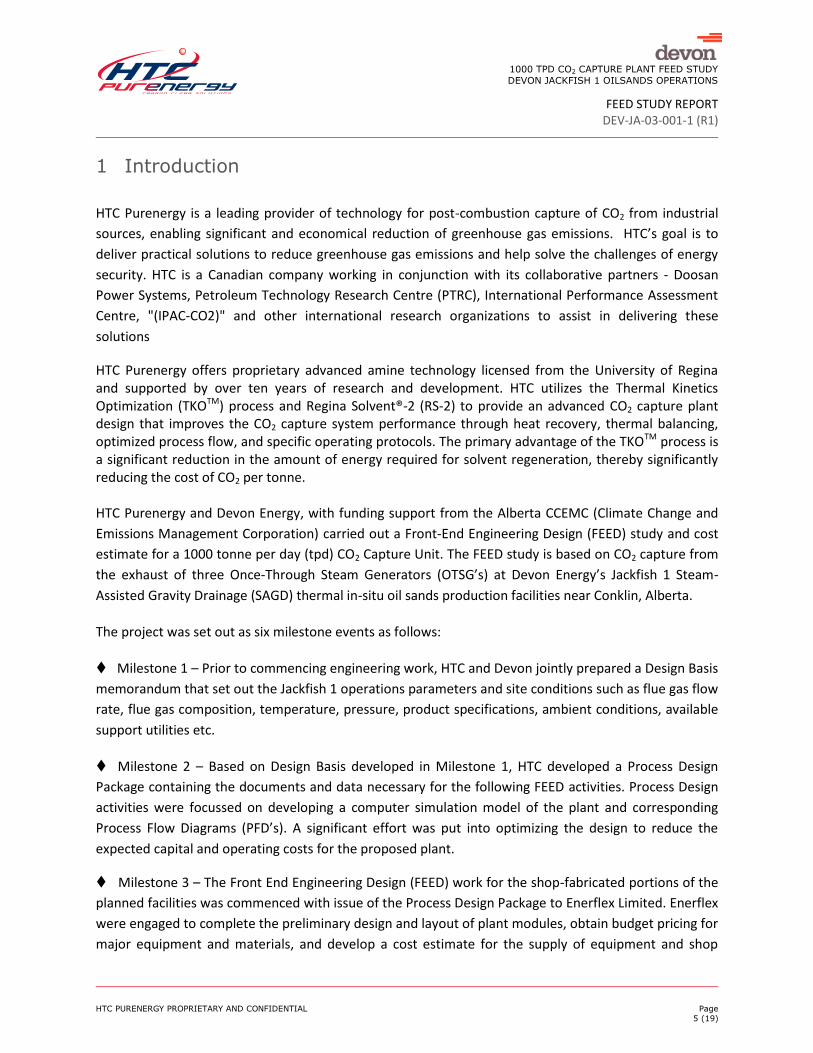
1 Introduction
HTC Purenergy is a leading provider of technology for post-combustion capture of CO2 from industrial
sources, enabling significant and economical reduction of greenhouse gas emissions. HTC’s goal is to
deliver practical solutions to reduce greenhouse gas emissions and help solve the challenges of energy
security. HTC is a Canadian company working in conjunction with its collaborative partners - Doosan
Power Systems, Petroleum Technology Research Centre (PTRC), International Performance Assessment
Centre, "(IPAC-CO2)" and other international research organizations to assist in delivering these
solutions
HTC Purenergy offers proprietary advanced amine technology licensed from the University of Regina and supported by over ten years of research and development. HTC utilizes the Thermal Kinetics Optimization (TKOTM) process and Regina Solvent®-2 (RS-2) to provide an advanced CO2 capture plant design that improves the CO2 capture system performance through heat recovery, thermal balancing, optimized process flow, and specific operating protocols. The primary advantage of the TKOTM process is a significant reduction in the amount of energy required for solvent regeneration, thereby significantly reducing the cost of CO2 per tonne. HTC Purenergy and Devon Energy, with funding support from the Alberta CCEMC (Climate Change and
Emissions Management Corporation) carried out a Front-End Engineering Design (FEED) study and cost
estimate for a 1000 tonne per day (tpd) CO2 Capture Unit. The FEED study is based on CO2 capture from
the exhaust of three Once-Through Steam Generators (OTSG’s) at Devon Energy’s Jackfish 1 Steam-
Assisted Gravity Drainage (SAGD) thermal in-situ oil sands production facilities near Conklin, Alberta.
The project was set out as six milestone events as follows:
Milestone 1 – Prior to commencing engineering work, HTC and Devon jointly prepared a Design Basis
memorandum that set out the Jackfish 1 operations parameters and site conditions such as flue gas flow
rate, flue gas composition, temperature, pressure, product specifications, ambient conditions, available
support utilities etc.
Milestone 2 – Based on Design Basis developed in Milestone 1, HTC developed a Process Design
Package containing the documents and data necessary for the following FEED activities. Process Design
activities were focussed on developing a computer simulation model of the plant and corresponding
Process Flow Diagrams (PFD’s). A significant effort was put into optimizing the design to reduce the
expected capital and operating costs for the proposed plant.
Milestone 3 – The Front End Engineering Design (FEED) work for the shop-fabricated portions of the
planned facilities was commenced with issue of the Process Design Package to Enerflex Limited. Enerflex
were engaged to complete the preliminary design and layout of plant modules, obtain budget pricing for
major equipment and materials, and develop a cost estimate for the supply of equipment and shop
1000 TPD CO2 CAPTURE PLANT FEED STUDY
DEVON JACKFISH 1 OILSANDS OPERATIONS
FEED STUDY REPORT DEV-JA-03-001-1 (R1)
HTC PURENERGY PROPRIETARY AND CONFIDENTIAL Page
6 (19)
fabricated process plant and pipe rack modules for the project. The FEED activities in this milestone
were centered on developing the Piping and Instrumentation Diagrams (P&ID’s) and specifications for
the major equipment. A primary objective of this milestone was to maximize the amount of the plant
that can be fabricated in transportable modules in a climate controlled shop environment offering
significant savings in labour costs compared to work on the plant site at ambient weather conditions.
Milestone 4 – Module design information developed by Enerflex was issued to Cimarron Engineering
Ltd., who was engaged to complete the preliminary design and cost estimate for site installation of the
plant. The Cimarron scope included site preparation, foundations, equipment and module
transportation and setting, mechanical installation, and electrical and control system materials and
installation.
Milestone 5– Following design activities, cost estimates were prepared for the shop-fabricated
modules by Enerflex Ltd and for the site installation work by Cimarron Engineering Ltd. Budgetary
quotations were requested for major equipment, materials and sub-contracts. In-house data was used
for labour costs. The estimate components were then built up to a total installed cost.
Milestone 6 –The final milestone event included preparation of the final project reports.
The Scope of the Study covers only the CO2 Post-Combustion Capture system including exhaust gas pre-conditioning to maximize efficiency and meet specified performance requirements.
The following items are excluded from the Scope of the Study:
CO2 compression and dehydration
CO2 transportation and storage
Utility source facilities (Fuel gas supply, De-mineralized water, Instrument air, Nitrogen etc.)
Waste water treatment facilities (waste water to be disposed using existing facilities)
This Report contains the following Deliverables:
Design Basis Description
Block Flow Diagram‐ defining major components of the Plant and battery limits
Process Description
Key Performance Indicators – showing flue gas inlet & outlet composition, conditions and flow
rates
Utility Summary – including power consumption for blowers, pumps and air-cooled heat
exchanger fans, and fuel gas for the Reboiler and Reclaimer
Engineering, Fabrications and Site installation Schedule
Installed cost estimate
1000 TPD CO2 CAPTURE PLANT FEED STUDY
DEVON JACKFISH 1 OILSANDS OPERATIONS
FEED STUDY REPORT DEV-JA-03-001-1 (R1)
HTC PURENERGY PROPRIETARY AND CONFIDENTIAL Page
7 (19)
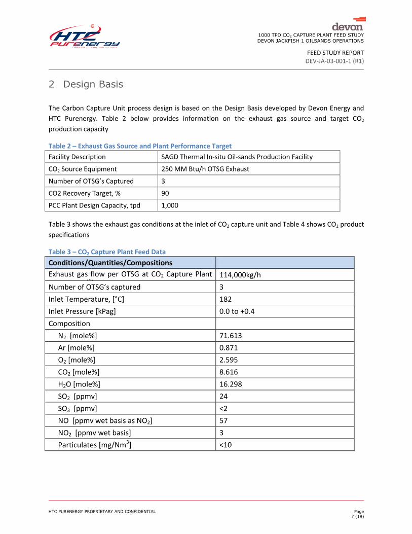
2 Design Basis
The Carbon Capture Unit process design is based on the Design Basis developed by Devon Energy and
HTC Purenergy. Table 2 below provides information on the exhaust gas source and target CO2
production capacity
Table 2 – Exhaust Gas Source and Plant Performance Target
Facility Description SAGD Thermal In-situ Oil-sands Production Facility
CO2 Source Equipment 250 MM Btu/h OTSG Exhaust
Number of OTSG’s Captured 3
CO2 Recovery Target, % 90
PCC Plant Design Capacity, tpd 1,000
Table 3 shows the exhaust gas conditions at the inlet of CO2 capture unit and Table 4 shows CO2 product
specifications
Table 3 – CO2 Capture Plant Feed Data
Conditions/Quantities/Compositions
Exhaust gas flow per OTSG at CO2 Capture Plant Inlet [kg/h] (1)
114,000kg/h
Number of OTSG’s captured 3
Inlet Temperature, [°C] 182
Inlet Pressure [kPag] 0.0 to +0.4
Composition
N2 [mole%] 71.613
Ar [mole%] 0.871
O2 [mole%] 2.595
CO2 [mole%] 8.616
H2O [mole%] 16.298
SO2 [ppmv] 24
SO3 [ppmv] <2
NO [ppmv wet basis as NO2] 57
NO2 [ppmv wet basis] 3
Particulates [mg/Nm3] <10

1000 TPD CO2 CAPTURE PLANT FEED STUDY
DEVON JACKFISH 1 OILSANDS OPERATIONS
FEED STUDY REPORT DEV-JA-03-001-1 (R1)
HTC PURENERGY PROPRIETARY AND CONFIDENTIAL Page
8 (19)
Table 4 - CO2 Product Specification
Product Stream Temperature, oC 40
Product Stream Pressure, kPag 45
CO2 Purity mole% (min, dry basis) 99
H2O mole% (max) Saturated – dehydration is outside battery limit
O2 mole% <0.010%
1000 TPD CO2 CAPTURE PLANT FEED STUDY
DEVON JACKFISH 1 OILSANDS OPERATIONS
FEED STUDY REPORT DEV-JA-03-001-1 (R1)
HTC PURENERGY PROPRIETARY AND CONFIDENTIAL Page
9 (19)
3 Process Design
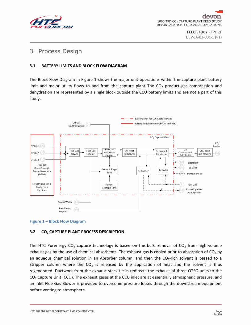
3.1 BATTERY LIMITS AND BLOCK FLOW DIAGRAM
The Block Flow Diagram in Figure 1 shows the major unit operations within the capture plant battery
limit and major utility flows to and from the capture plant The CO2 product gas compression and
dehydration are represented by a single block outside the CCU battery limits and are not a part of this
study.
Figure 1 – Block Flow Diagram
3.2 CO2 CAPTURE PLANT PROCESS DESCRIPTION
The HTC Purenergy CO2 capture technology is based on the bulk removal of CO2 from high volume
exhaust gas by the use of chemical absorbents. The exhaust gas is cooled prior to absorption of CO2 by
an aqueous chemical solution in an Absorber column, and then the CO2-rich solvent is passed to a
Stripper column where the CO2 is released by the application of heat and the solvent is thus
regenerated. Ductwork from the exhaust stack tie-in redirects the exhaust of three OTSG units to the
CO2 Capture Unit (CCU). The exhaust gases at the CCU inlet are at essentially atmospheric pressure, and
an inlet Flue Gas Blower is provided to overcome pressure losses through the downstream equipment
before venting to atmosphere.
Flue Gas Cooler
Stripper &Condenser
Reboiler
Off Gas to Atmosphere
Residue to Disposal
CO2 Capture Plant
Battery limit for CO2 Capture Plant
Once-Through Steam Generator
(OTSG)
DEVON Jackfish 1 Production
Facilities
CO2 Product
Instrument air
Solvent
Flue Gas Blower
Electricity
Fuel Gas
Exhaust gas toAtmosphere
Excess Water
ReclaimerSolvent Surge
Tank
Solvent Storage Tank
L/R Heat Exchanger
Absorber with Wash
Section
CO2 Compression &
Dehydration
CO2 send out pipeline
Battery limit between DEVON and HTC
Flue gas
OTSG-1
OTSG-2
OTSG-3
1000 TPD CO2 CAPTURE PLANT FEED STUDY
DEVON JACKFISH 1 OILSANDS OPERATIONS
FEED STUDY REPORT DEV-JA-03-001-1 (R1)
HTC PURENERGY PROPRIETARY AND CONFIDENTIAL Page
10 (19)
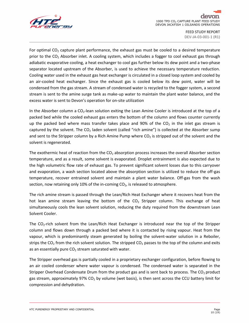
For optimal CO2 capture plant performance, the exhaust gas must be cooled to a desired temperature
prior to the CO2 Absorber inlet. A cooling system, which includes a fogger to cool exhaust gas through
adiabatic evaporative cooling, a heat exchanger to cool gas further below its dew point and a two-phase
separator located upstream of the Absorber, is used to achieve the necessary temperature reduction.
Cooling water used in the exhaust gas heat exchanger is circulated in a closed loop system and cooled by
an air-cooled heat exchanger. Since the exhaust gas is cooled below its dew point, water will be
condensed from the gas stream. A stream of condensed water is recycled to the fogger system, a second
stream is sent to the amine surge tank as make-up water to maintain the plant water balance, and the
excess water is sent to Devon’s operation for on-site utilization
In the Absorber column a CO2-lean solution exiting the Lean Amine Cooler is introduced at the top of a
packed bed while the cooled exhaust gas enters the bottom of the column and flows counter currently
up the packed bed where mass transfer takes place and 90% of the CO2 in the inlet gas stream is
captured by the solvent. The CO2 laden solvent (called “rich amine”) is collected at the Absorber sump
and sent to the Stripper column by a Rich Amine Pump where CO2 is stripped out of the solvent and the
solvent is regenerated.
The exothermic heat of reaction from the CO2 absorption process increases the overall Absorber section
temperature, and as a result, some solvent is evaporated. Droplet entrainment is also expected due to
the high volumetric flow rate of exhaust gas. To prevent significant solvent losses due to this carryover
and evaporation, a wash section located above the absorption section is utilized to reduce the off-gas
temperature, recover entrained solvent and maintain a plant water balance. Off-gas from the wash
section, now retaining only 10% of the in-coming CO2, is released to atmosphere.
The rich amine stream is passed through the Lean/Rich Heat Exchanger where it recovers heat from the
hot lean amine stream leaving the bottom of the CO2 Stripper column. This exchange of heat
simultaneously cools the lean solvent solution, reducing the duty required from the downstream Lean
Solvent Cooler.
The CO2-rich solvent from the Lean/Rich Heat Exchanger is introduced near the top of the Stripper
column and flows down through a packed bed where it is contacted by rising vapour. Heat from the
vapour, which is predominantly steam generated by boiling the solvent‐water solution in a Reboiler,
strips the CO2 from the rich solvent solution. The stripped CO2 passes to the top of the column and exits
as an essentially pure CO2 stream saturated with water.
The Stripper overhead gas is partially cooled in a proprietary exchanger configuration, before flowing to
an air cooled condenser where water vapour is condensed. The condensed water is separated in the
Stripper Overhead Condensate Drum from the product gas and is sent back to process. The CO2 product
gas stream, approximately 97% CO2 by volume (wet basis), is then sent across the CCU battery limit for
compression and dehydration.
1000 TPD CO2 CAPTURE PLANT FEED STUDY
DEVON JACKFISH 1 OILSANDS OPERATIONS
FEED STUDY REPORT DEV-JA-03-001-1 (R1)
HTC PURENERGY PROPRIETARY AND CONFIDENTIAL Page
11 (19)
The regenerated lean amine solution is removed from the Stripper bottom and passes through the
Lean/Rich Heat Exchanger and is cooled against the rich amine stream going to the Stripper. The lean
amine solution is then sent back to the CO2 Absorber Column via an air cooled Lean Solvent Cooler,
which provides control of the temperature of the lean solvent.
In the CO2 absorption/stripping process, the base amine components in the solvent react with O2 and
other gases such as NO2, SO2 and SO3 in the flue gas to form “complex” heat stable salts that cannot be
thermally regenerated. In addition, some organic degradation products can be formed through side
reactions between flue gas impurities, the amine solvent and/or the heat stable salts.
Heat stable salts and degradation products, if allowed to accumulate in the solvent, will decrease the
solvent CO2 capture efficiency. Therefore, a slip stream of lean amine solvent leaving the Stripper
bottom is sent to a Reclaimer to remove degradation compounds and recover amine from the heat
stable salts. Fuel gas is used to provide the necessary heat required to maintain the Reclaimer operating
temperature. Evaporated solvent vapour is condensed by an air cooled heat exchanger and the
recovered solvent is pumped back to the Amine Surge Tank. The Reclaimer waste stream, containing the
heat stable salts, degradation products, as well as a small amount of unrecovered solvent, leaves the
capture plant battery limit for waste processing and/or incineration by a commercial waste
management company.
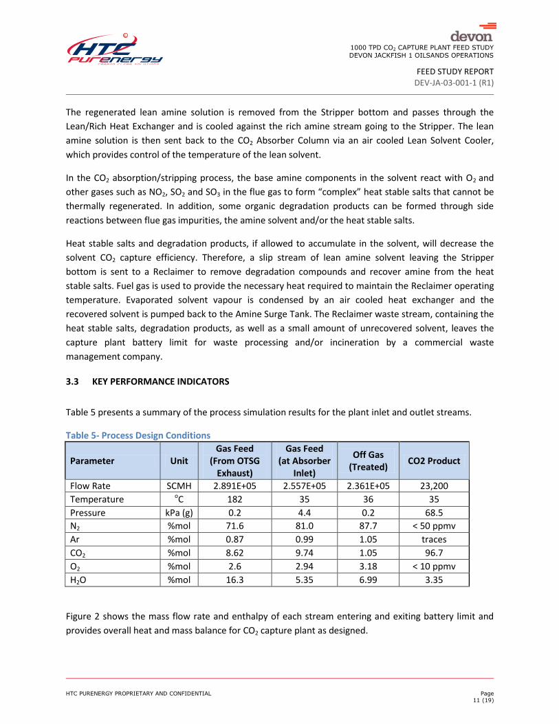
3.3 KEY PERFORMANCE INDICATORS
Table 5 presents a summary of the process simulation results for the plant inlet and outlet streams.
Table 5- Process Design Conditions
Parameter Unit Gas Feed
(From OTSG Exhaust)
Gas Feed (at Absorber
Inlet)
Off Gas (Treated)
CO2 Product
Flow Rate SCMH 2.891E+05 2.557E+05 2.361E+05 23,200
Temperature oC 182 35 36 35
Pressure kPa (g) 0.2 4.4 0.2 68.5
N2 %mol 71.6 81.0 87.7 < 50 ppmv
Ar %mol 0.87 0.99 1.05 traces
CO2 %mol 8.62 9.74 1.05 96.7
O2 %mol 2.6 2.94 3.18 < 10 ppmv
H2O %mol 16.3 5.35 6.99 3.35
Figure 2 shows the mass flow rate and enthalpy of each stream entering and exiting battery limit and
provides overall heat and mass balance for CO2 capture plant as designed.

1000 TPD CO2 CAPTURE PLANT FEED STUDY
DEVON JACKFISH 1 OILSANDS OPERATIONS
FEED STUDY REPORT DEV-JA-03-001-1 (R1)
HTC PURENERGY PROPRIETARY AND CONFIDENTIAL Page
12 (19)
Flue Gas Cooler
Stripper &Condenser
Reboiler(129.75 GJ/hr)
Off Gas to
Atmosphere
Residue to Disposal
CO2 Capture Plant
Battery limit for CO2 Capture Plant
Once-Through Steam Generator (OTSG)
DEVON Jackfish 1 Production
Facilities
Instrument air
Solvent
Flue Gas Blower
Electrical Power Supply= 2575 kW
Fuel Gas
Exhaust gas toAtmosphere
Excess Water
Reclaimer(Intermittent
Operation)
Solvent Surge Tank
Solvent Storage Tank
L/R Heat Exchanger
Absorber with Wash
Section
CO2 Compression
& Dehydration
CO2 send out pipeline
Battery limit between DEVON and HTC
Flue gas
342,000 kg/hr
173,500 J/kg
182 oC
0.2 kPa (g)
276,900 kg/hr
11,499 J/kg
36 oC
0.2 kPa (g)
42,331 kg/hr
7,040 J/kg
35 oC
68.5 kPa (g)
22,745 kg/hr
-2,403,000 J/kg
35 oC
349 kPa (g)
Intermittent Stream
Intermittent
Solvent Make-
up
Total Cooling Duty = 230 GJ/hr
Figure 2 - Heat and Mass Balance over battery limit
1000 TPD CO2 CAPTURE PLANT FEED STUDY
DEVON JACKFISH 1 OILSANDS OPERATIONS
FEED STUDY REPORT DEV-JA-03-001-1 (R1)
HTC PURENERGY PROPRIETARY AND CONFIDENTIAL Page
13 (19)
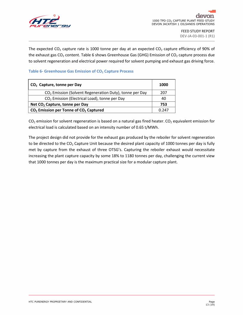
The expected CO2 capture rate is 1000 tonne per day at an expected CO2 capture efficiency of 90% of
the exhaust gas CO2 content. Table 6 shows Greenhouse Gas (GHG) Emission of CO2 capture process due
to solvent regeneration and electrical power required for solvent pumping and exhaust gas driving force.
Table 6- Greenhouse Gas Emission of CO2 Capture Process
CO2 Capture, tonne per Day 1000
CO2 Emission (Solvent Regeneration Duty), tonne per Day 207
CO2 Emission (Electrical Load), tonne per Day 40
Net CO2 Capture, tonne per Day 753
CO2 Emission per Tonne of CO2 Captured 0.247
CO2 emission for solvent regeneration is based on a natural gas fired heater. CO2 equivalent emission for
electrical load is calculated based on an intensity number of 0.65 t/MWh.
The project design did not provide for the exhaust gas produced by the reboiler for solvent regeneration
to be directed to the CO2 Capture Unit because the desired plant capacity of 1000 tonnes per day is fully
met by capture from the exhaust of three OTSG’s. Capturing the reboiler exhaust would necessitate
increasing the plant capture capacity by some 18% to 1180 tonnes per day, challenging the current view
that 1000 tonnes per day is the maximum practical size for a modular capture plant.

1000 TPD CO2 CAPTURE PLANT FEED STUDY
DEVON JACKFISH 1 OILSANDS OPERATIONS
FEED STUDY REPORT DEV-JA-03-001-1 (R1)
HTC PURENERGY PROPRIETARY AND CONFIDENTIAL Page
14 (19)
3.4 UTILITY SUMMARY
Total electrical power required to operate the blower, pumps and air-cooled exchanger fans is
presented in Table 6.
Table 7 - Electrical Power Consumption
Equipment Description Operating Electrical
Load (kW)
Flue Gas Blower 645
Air-cooled Exchangers (Fan Power) 1580
Pumps 310
Reclaimer Package (Intermittent operation) 40
Total Electrical Power Consumption 2575
The plant is designed for a natural gas-fired Reboiler and a natural gas-fired heater for the Reclaimer
having fuel demand as shown in Table 7.
Table 8 - Fuel Consumption
Equipment Description Process
Heat Duty Fuel Gas
Consumption
GJ/hr m3/hr
Reboiler 130 4080
Reclaimer (On-stream Factor = 0.05) 6.83 215
Note: Fuel gas consumption is calculated based on Gross Heating Value of 39.76 MJ/m3 and 80%
efficiency.
3.5 PROCESS OPTIMIZATION
It was assumed for the purposes of the study that the CO2 Capture Unit would stand-alone in terms of
process heating and cooling. It is recognized that opportunities may exist for heat integration between
the CO2 plant and the SAGD facilities that would improve the thermal efficiency of the combined
operations and reduce overall energy consumption. Such opportunities would be evaluated on a project
specific basis.
The relatively high temperature (180oC) of the exhaust gas results in a large cooling duty to cool the
stream down to the required temperature at the Absorber inlet to maintain the optimum solvent
loading capacity. An initial evaluation was completed to select the process configuration for the exhaust
gas cooling system for the purposes of the study.

1000 TPD CO2 CAPTURE PLANT FEED STUDY
DEVON JACKFISH 1 OILSANDS OPERATIONS
FEED STUDY REPORT DEV-JA-03-001-1 (R1)
HTC PURENERGY PROPRIETARY AND CONFIDENTIAL Page
15 (19)
The selected system comprises a “Fogger” followed by a water cooled heat exchanger. The Fogger
consists of system to spray water into the hot exhaust gas providing evaporative cooling. The water
cooled exchanger then provides further cooling down to the desired Absorber inlet temperature and
condensed water is separated from the cooled exhaust gas in a two-phase separator. Heat transferred
to the closed loop cooling water system is rejected to atmosphere in an air-cooled exchanger.
Alternatively, flue gas cooling can be achieved by a Direct Contact Cooler (DCC) packed bed column
where hot exhaust gas is directly contacted with circulating water and heat transfer takes place from gas
phase to liquid phase. The hot circulating water is then cooled via air-cooled heat exchanger. The initial
evaluation favoured the Fogger/exchanger system over the DCC system.
1000 TPD CO2 CAPTURE PLANT FEED STUDY
DEVON JACKFISH 1 OILSANDS OPERATIONS
FEED STUDY REPORT DEV-JA-03-001-1 (R1)
HTC PURENERGY PROPRIETARY AND CONFIDENTIAL Page
16 (19)
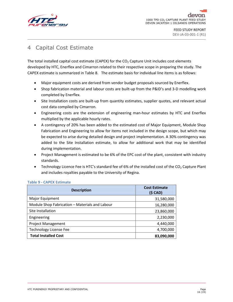
4 Capital Cost Estimate
The total installed capital cost estimate (CAPEX) for the CO2 Capture Unit includes cost elements
developed by HTC, Enerflex and Cimarron related to their respective scope in preparing the study. The
CAPEX estimate is summarized in Table 8. The estimate basis for individual line items is as follows:
Major equipment costs are derived from vendor budget proposals sourced by Enerflex.
Shop fabrication material and labour costs are built-up from the P&ID’s and 3-D modelling work
completed by Enerflex.
Site Installation costs are built-up from quantity estimates, supplier quotes, and relevant actual
cost data compiled by Cimarron.
Engineering costs are the extension of engineering man-hour estimates by HTC and Enerflex
multiplied by the applicable hourly rates.
A contingency of 20% has been added to the estimated cost of Major Equipment, Module Shop
Fabrication and Engineering to allow for items not included in the design scope, but which may
be expected to arise during detailed design and project implementation. A 30% contingency was
added to the Site Installation estimate, to allow for additional work that may be identified
during implementation.
Project Management is estimated to be 6% of the EPC cost of the plant, consistent with industry
standards.
Technology Licence Fee is HTC’s standard fee of 6% of the installed cost of the CO2 Capture Plant
and includes royalties payable to the University of Regina.
Table 9 - CAPEX Estimate
Description Cost Estimate
($ CAD)
Major Equipment 31,580,000
Module Shop Fabrication – Materials and Labour 16,280,000
Site Installation 23,860,000
Engineering 2,230,000
Project Management 4,440,000
Technology License Fee 4,700,000
Total Installed Cost 83,090,000
1000 TPD CO2 CAPTURE PLANT FEED STUDY
DEVON JACKFISH 1 OILSANDS OPERATIONS
FEED STUDY REPORT DEV-JA-03-001-1 (R1)
HTC PURENERGY PROPRIETARY AND CONFIDENTIAL Page
17 (19)
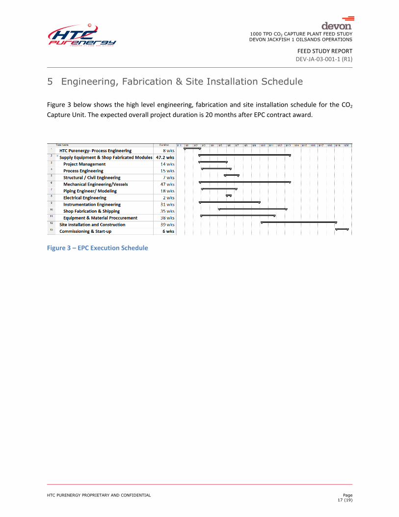
5 Engineering, Fabrication & Site Installation Schedule
Figure 3 below shows the high level engineering, fabrication and site installation schedule for the CO2
Capture Unit. The expected overall project duration is 20 months after EPC contract award.
Figure 3 – EPC Execution Schedule
1000 TPD CO2 CAPTURE PLANT FEED STUDY
DEVON JACKFISH 1 OILSANDS OPERATIONS
FEED STUDY REPORT DEV-JA-03-001-1 (R1)
HTC PURENERGY PROPRIETARY AND CONFIDENTIAL Page
18 (19)
6 Recommendations
Additional engineering needs to be completed to definitively conclude the most cost-effective inlet
exhaust gas cooling process configuration. The study must include both the cost of capital and the cost
of energy required by the system.
A specific project should include a front-end study of the potential for heat integration to minimize the
energy penalty for the combined production/capture operations. Potential exists to transfer high level
heat from the SAGD operations to the CO2 capture operations in exchange for low level heat available
from the capture and subsequent compression operations.

1000 TPD CO2 CAPTURE PLANT FEED STUDY
DEVON JACKFISH 1 OILSANDS OPERATIONS
FEED STUDY REPORT DEV-JA-03-001-1 (R1)
HTC PURENERGY PROPRIETARY AND CONFIDENTIAL Page
19 (19)
7 Conclusions
The study work has shown the technical feasibility of fabricating and installing a modular 1000
tonne per day (tpd) CO2 capture plant.
The indicated project execution schedule of 20 months from contract award through start-up
reflects the expected advantages of HTC’s approach of employing a standardized design with a
modular shop-fabricated plant.
The 1000 tpd sizing is a very good fit for “typical” SAGD developments such as Devon’s Jackfish 1
that deploy 250 MMBtu/hr OTSG’s, in that a 1000 tpd unit can capture the exhaust off three
boilers.
The CO2 capture process configuration is of one absorber and one stripper type. Absorber
diameter is 7.62 m and stripper diameter is 3.35 m. Total CO2 Capture plant foot print for this
modular design is estimated to be 8000 m2 (80m X 100m).
The 1000 tpd modular approach will allow operators to phase-in CO2 capture in SAGD
operations in 3-boiler increments rather than considering capture from an entire facility at once.
The estimated CAPEX for the project spread simply over 20 years of production at design rate
gives an indicated CAPEX component of capture cost of about $11.98/tonne.
Using a weighted average cost of capital of 8%, assuming a long-term average plant throughput
of 85% of design rate, and assuming a plant availability of 95%, the CAPEX component of CO2
capture cost from SAGD facilities will be under $37/tonne.
HTC estimates the operating cost of a CO2 capture unit to be approximately $30/tonne including
fuel costs at $5/GJ ($13/tonne).
The indicated total CO2 capture cost at 8% cost of capital is under $70/tonne.
It is probable that the fuel cost can be significantly reduced through project specific heat
integration efforts and optimization of the inlet cooling system.
It is recognized that the cost of emissions reduction must include, in addition to the cost of
capture, consideration of additional emissions from capture operations as well as compression,
transportation and drilling and injection costs. However, as the Alberta Carbon Capture and
Storage Development Council report states, it is generally regarded that the cost of capture is 70
to 90% of the cost of emissions reduction.
The study results indicate that the previously published view of the expected cost of CO2 emission
reduction from SAGD operations to be from $175 to $230 per tonne is significantly overstated.