
Vega V250CE
16
V250CE www.vegacylinder.com Short Stroke Block Cylinder With Magnetic Switches 250 Bar, Light Series Cilindri oleodinamici a corsa breve con sensori magnetici di fine corsa 250 bar, serie leggera Cat.V250CE.2012.00.GB+IT Cylinders ®
description
Light Duty Short Stroke
Transcript of Vega V250CE

V25
0CE
www.vegacylinder.com
Short Stroke Block Cylinder With MagneticSwitches 250 Bar, Light Series
Cilindri oleodinamici a corsa breve con sensorimagnetici di fine corsa 250 bar, serie leggera
Cat.V250CE.2012.00.GB+IT
Cylinders
®

E2
V25
0CE
Order compilation symbols - Simbologia per redigere un ordine
Cylinder MODEL V250CEModello cilindro V250CE
Cylinder BORE (ØX)ALESAGGIO cilindro- P. E4
Clamping STYLEFissaggio - P. E5-E7
Oil Ports TYPETIPO di orifizi- P. E5-E7
Oil Ports POSITIONPOSIZIONE orifizi- P. E5-E7
Rod End TYPEEstremità STELO- P. E8
Cylinder VERSIONVERSIONE Cilindro- P. E8
Rod AccessoriesAccessori Stelo- P. E10
Stroke (Z)Corsa- P. E4
Magnetic SwitchesSensori Magnetici- P. E9
Longitudinal through holesFori passanti longitudinali
Key wayPiedino
ØX = Bore AlesaggioØY = Rod Stelo
+
Pay attention to the BEST PRICE cylinders! By selecting all the “BEST PRICE” options - bore, stroke, mounting, rod and oil ports - you save up to 30% on cylinder price and you will have stock cylinders in Italy, China and other locations. Best price and service with same quality!
Attenzione ai cilindri BEST PRICE! Selezionando tutte le opzioni “BEST PRICE” - alesaggio, corsa, fissaggio, orifizi e stelo - potrete configurare cilindri con prezzo ridotto fino al 30%, disponibili a magazzino in Italia, Cina ed alcune altre località nel mondo. Miglior prezzo e miglior servizio con uguale qualità!
M
HD
E
F
R
Z
ØXØY025 040 063
100032 050 080
C
CE 025 E G H G M 020
MTA10x150 MSU2
AccessoriesAccessori
MSU2MSU3
Male Thread - Filetto Maschio MTAFloating Joint - Testa a martello MFAFloating Joint with Female - Testa a martello con femmina DFA
G BSP (GAS) thread standard - Filetto BSP (GAS) standard
N NPT thread - Filetto NPT
O Manifold with o-rings - Integrati con o-rings
H Left side (threaded) - Sinistra (filettati)
M Right side (threaded) - Destra (filettati)
F Front side (o-rings) - Frontale (o-rings)
E Bottom side (o-rings) - Lato inferiore (o-rings)
R Rear side (o-rings) - Posteriori inferiore (o-rings)
D Left+Right side (threaded) - Sinistro+destro (filettato)
G Female Metric thread - Filetto femmina Metrico
I Female UNF thread - Filetto femmina UNF
CE
E
Magnetic switches preset Predisposto ai sensori magnetici MWithout magnetic switches presetNon predisposto ai sensori magnetici N
020 050 080

E2 E3
V25
0CE
Product presentation and general features Presentazione del prodotto e caratteristiche
Cylinder ACCESSORIES - ACCESSORI cilindro
The V250CBM cylinders have been specially designed for being extremely compact and for applying the integrated end stroke MAGNETIC SWITCHES. Furthermore their construction permits a high standardization with consequent lower price and immediate delivery time. Available bores: from 25 mm to 100 mm and strokes 20, 50 and 80 mm. These cylinders are ideal for short stroke slides and cores on plastic injection moulds. Due to the light construction, the use of these cylinders for heavy duties is not recommended (for example for moving of extraction plates or for die casting moulds)
I cilindri serie V250CBM sono concepiti per essere estremamente compatti e per essere dotati di SENSORI MAGNETICI di fine corsa. La loro costruzione permette di essere altamente standardizzati e quindi di ridurne il prezzo ed avere tempi di consegna immediati. Con alesaggi da 25 a 100 mm e corse 20 o 50 mm. Questi cilindri sono ideali su stampi per iniezione plastica per movimentazione di punzoni radiali o carrelli con corse brevi. La costruzione leggera non li rende adatti ad applicazioni “pesanti” in genere (ad esempio movimentazione piastre di estrazione e su stampi di pressofusione d’alluminio).
Special aluminum alloy piston, in two segments with syntherized magnet ring and PTFE+ Carbographite seals with FKM Oring. Guide rings are in polyester resin for a high resistance and a long life.
Special aluminum alloy body for high pressure resistance and adapt for the magnetic switches.
Steel rod seals-cartridge with PTFE+ Carbographite seals with FKM O-ring. Guide rings are in polyester resin for a high resistance and a long life. This solution with separate seals lodging from the body simplifies the seals replacement.
End stroke magnetic switches, in option (the picture shows theexternal box. Switches are inside the cylinder). (see page E9).
Support key-way for foot clamping (See E13).
Chiavetta di supporto per fissaggio a piedino (vedi E13).
Thermo isolating plate, ideal forhigh temperature applications. (See E12-13).
Chrome-plated steel rod, hardened and polished. Thickness of chromium plating 20 ųm and surface finish 0,4 ųm Ra, for a longer durability of the seals.
Unidirectional flow controller, to regulate the speed of the piston, and steel hydraulic pipe fittings for flow controller (see accessories catalogue).
Rod end accessories: male thread with locknut; floating joint with locknut and floating joint with female of the floating joint, for increasing the connection options between rod and slide.
Pistone in lega speciale d’alluminio in due settori con inserito anello magnetico sinterizzato. Guarnizioni in PTFE+Carbografite ed O-ring in FKM. Fasce di guida in resina Poliestere per un’alta resistenza allo schiacciamento ed una lunga durata.
Stelo in acciaio bonificato, cromato e lucidato. Spessore cromatura 20 ųm e finitura superficiale 0,4 ųm Ra, che prolunga notevolmente la durata delle guarnizioni.
Cartuccia porta guarnizioni per lo stelo in acciaio, con guarnizioni in PTFE+Carbografite ed Oring in FKM. Fasce di guida in resina Poliestere per un’alta resistenza allo schiacciamento ed una lunga durata. La soluzione della cartuccia separata facilita la sostituzione delle guarnizioni.
Corpo in lega speciale d’alluminio per un’elevata resistenza alla pressione ed adatto all’uso dei sensori magnetici.
Regolatore di f lusso unidirezionale per regolare la velocità del pistone e nippli di connessione accessori oleodinamici (vedi catalogo accessori).
Accessori per lo stelo: terminale maschio con controdado, testa a martello con controdado e testa a martello con femmina della testa a martello, per offrire ulteriori opzioni di connessione fra stelo ed applicazione.
Sensori magnetici di fine corsa, opzionali (l’immagine mostra solo la parte visibile all’esterno del cilindro. I sensori sono inseriti nel cilindro. (vedi E9)
Piastra isolante, ideale per applicazioni ad alte temperature. (vedi E12-13).
E4
V25
0CE
ØX ØY
8 MPa - 80 bar1160 PSI
10 MPa - 100 bar1450 PSI
12,5 MPa - 125 bar1812 PSI
16 MPa - 160 bar2320 PSI
20 MPa - 200 bar2900 PSI
ØXPush Pull Push Pull Push Pull Push Pull Push Pull
Spinta Trazione Spinta Trazione Spinta Trazione Spinta Trazione Spinta Trazione
025 18 393 189 491 236 613 295 785 378 981 473 25
032 22 643 339 804 424 1005 530 1286 678 1608 848 32
040 22 1005 701 1256 876 1570 1095 2010 1402 2512 1752 40
050 28 1570 1078 1963 1347 2453 1684 3140 2155 3925 2694 50
063 28 2493 2000 3116 2500 3895 3125 4985 4000 6231 5000 63
080 36 4019 3205 5024 4007 6280 5008 8038 6411 - - 80
100 45 6280 5008 7850 6260 9813 7825 12560 10017 - - 100
020 050 080
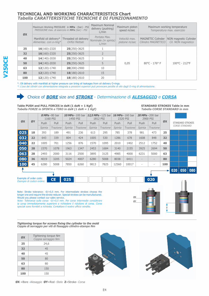
TECHNICAL AND WORKING CHARACTERISTICS ChartTabella CARATTERISTICHE TECNICHE E DI FUNZIONAMENTO
Choice of BORE size and STROKE - Determinazione di ALESAGGIO e CORSA
*: Oil delivery with manifold at higher pressure can bring oil leakages from oil delivery O-rings.*: L’uso dei cilindri con alimentazione integrata a pressioni superiori può provocare perdite di olio dagli O-ring di alimentazione.
Table PUSH and PULL FORCES in daN (1 daN = 1 Kgf)Tabella FORZE in SPINTA e TIRO in daN (1 daN = 1 Kgf)
STANDARD STROKES Table in mmTabella CORSE STANDARD in mm
Example of order code:Esempio di codice ordine: CE 025 E G H G M 020
ØX
Maximum Working PRESSURE in MPa - (bar) - PSIPRESSIONE max. di esercizio in MPa (bar) - PSI
Maximum Nominal delivery (pushing)
L/min
Maximum piston speed m/sec
Maximum working temperatureTemperatura max. esercizio
Manifold oil delivery*Alimentaz. con o-ring*
Threaded oil deliveryOrifizi filettati
Portata Max. Nominale (in spinta)
L/min
Velocità max. pistone m/sec
MAGNETIC CylinderCilindro MAGNETICO
NON magnetic CylinderCil. NON magnetico
25 16(160)-2320 25(250)-3625 1
0,05 80°C - 176° F 100°C - 212°F
32 16(160)-2320 25(250)-3625 2
40 14(140)-2030 25(250)-3625 3
50 14(140)-2030 25(250)-3625 5
63 12(120)-1740 20(200)-2900 10
80 12(120)-1740 18(180)-2610 15
100 12(120)-1740 18(180)-2610 20
STANDARD STROKESCORSE STANDARD
Note: Stroke tolerance: -0/+0,5 mm. For intermediate strokes choose the longer one and require the stroke reducer. Special strokes can be manufactured. Would you please contact our sales service.Note: Tolleranza sulla corsa: -0/+0,5 mm. Per corse intermedie considerare la corsa immediatamente superiore e richiedere il riduttore di corsa. Corse speciali sono fornibili a richiesta. Contattare il nostro ufficio vendite.
ØX =Bore -Alesaggio ØY=Rod -Stelo Z=Stroke- Corsa
ØX
ØY
Z
ØX Tightening torque NmCoppia serraggio Nm
25 24,6
32 45
40 45
50 80
63 80
80 150
100 150
Tightening torque for screws fixing the cylinder to the moldCoppie di serraggio per viti di fissaggio cilindro-stampo Nm

E4 E5
V25
0CE
Choice of CLAMPING style and OIL DELIVERYDeterminazione di FISSAGGIO e ORIFIZI
Key-way clamping with BSP (GAS) threaded oil delivery, LEFT sideFissaggio a piedino con orifizi filettati BSP (GAS), lato SINISTRO
Key-way clamping with NPT threaded oil delivery, LEFT sideFissaggio a piedino con orifizi filettati NPT, lato SINISTRO
#1 :- If this clamping style is adopted and oil pressure in the cylinder is higher than 160 bar = 2320 PSI, we advise to use a holding “wall” to avoid any deflection.#1 :- Se con questo fissaggio si usa il cilindro a pressioni oltre 160 bar = 2320 PSI, consigliamo l’uso di un sostegno come da disegno, per evitare ogni flessione.
Example of order code:Esempio di codice ordine:
Key-way clamping with BSP (GAS) threaded oil delivery, RIGHT sideFissaggio a piedino con orifizi filettati BSP (GAS), lato DESTRO
Key-way clamping with NPT threaded oil delivery, RIGHT sideFissaggio a piedino con orifizi filettati NPT, lato DESTRO
Stroke Corsa20mm
Stroke Corsa>= 50mm
CE 025 E G H G M 020
E G H
E N H
E G M
E N M
NOTE: All cylinders with BSP right side oil delivery and NPT left or right side oil delivery CAN HAVE A TIP ON THE SIDE OPPOSITE THE OIL DELIVERY.See measuring “T2” and ØT1 (see page P.E6)NOTA: I cilindri con alimentazione BSP destra o NPT destra e sinistra POTREBBERO AVERE UN TAPPO SUL LATO OPPOSTO ALL’ ALIMENTAZIONE Vedere le quote“T2” e ØT1 (vedi pagina P.E6)
ØX ØY Z T C+ A B F G H L M P ØQ ØQ1 R SH10 S1 ØSB
f8 V W WHNPT BSP
25 1820 -
57 65 45 30 50 9 12 22 1/4” 1/4” 8,5 13,5 50 10 2 32 6,5 37 1450 4080 70
32 2220 -
60 75 55 35 55 11 12 22 1/4” 1/4” 10,5 16,5 55 12 3 34 8 40 1550 4080 70
40 2220 -
73 85 63 40 63 11 14 24 1/4” 1/4” 10,5 16,5 63 12 3 34 7 43 1750 4580 75
50 2820 -
75 100 75 45 76 13 14,5 25 1/4” 1/4” 13 19 76 15 5 42 8 45 2050 4580 75
63 2820 -
85 115 90 55 90 13 21 29 3/8” 3/8” 13 19 90 15 5 50 7 55 2050 4080 70
80 3620 -
100 140 110 75 110 17 25 35 1/2” 1/2” 17 25 110 20 5 60 7 60 2050 40- -
100 4520 -
110 170 140 95 135 17 28 37 1/2” 1/2” 17 25 135 20 5 72 8 70 2550 30- -
ØX = Bore Alesaggio ØY = Rod Stelo Z = Stroke Corsa (P.E4) eg. ØX = 25 , ØY = 18, Z = 20mm : C + Z = 57 + 20 = 77 mm
NOTE: For dimensions where no tolerance is indicated, refer to DIN norm 7168-mNOTA: Per le dimensioni senza indicazione di tolleranza, riferirsi alla norma DIN 7168-m
E6
V25
0CE
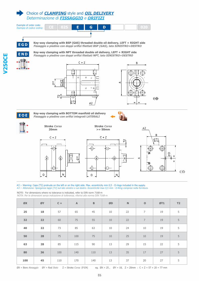
Choice of CLAMPING style and OIL DELIVERYDeterminazione di FISSAGGIO e ORIFIZI
Key-way clamping with BSP (GAS) threaded double oil delivery, LEFT + RIGHT sideFissaggio a piedino con doppi orifizi filettati BSP (GAS), lato SINISTRO+DESTRO
Key-way clamping with NPT threaded double oil delivery, LEFT + RIGHT sideFissaggio a piedino con doppi orifizi filettati NPT, lato SINISTRO+DESTRO
#2 :- Warning: Caps (T2) protrude on the left or on the right side. Max. eccentricity mm 0,5 - O-rings included in the supply.#2 :- Attenzione: Sporgenza tappi (T2) sul lato sinistro o sul destro. Eccentricità max 0,5 mm - O-Ring compresi nella fornitura.
Example of order code:Esempio di codice ordine:
Key-way clamping with BOTTOM manifold oil deliveryFissaggio a piedino con orifizi integrati LATERALI
Stroke Corsa20mm
Stroke Corsa>= 50mm
CE 025 E G D G M 020
E G D
E N D
E O E
ØX ØY C + A B ØD N O ØT1 T2
25 18 57 65 45 10 22 7 19 5
32 22 60 75 55 10 22 7 19 5
40 22 73 85 63 10 24 10 19 5
50 28 75 100 75 10 25 10 19 5
63 28 85 115 90 13 29 15 22 5
80 36 100 140 110 13 35 17 27 5
100 45 110 170 140 13 37 20 27 5
ØX = Bore Alesaggio ØY = Rod Stelo Z = Stroke Corsa (P.E4) eg. ØX = 25 , ØY = 18, Z = 20mm : C + Z = 57 + 20 = 77 mm
NOTE: For dimensions where no tolerance is indicated, refer to DIN norm 7168-mNOTA: Per le dimensioni senza indicazione di tolleranza, riferirsi alla norma DIN 7168-m
E6 E7
V25
0CE
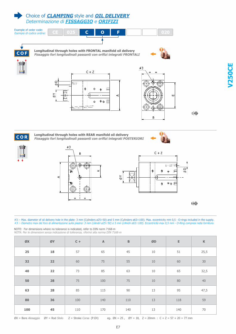
Choice of CLAMPING style and OIL DELIVERYDeterminazione di FISSAGGIO e ORIFIZI
Longitudinal through holes with FRONTAL manifold oil deliveryFissaggio fori longitudinali passanti con orifizi integrati FRONTALI
#3 :- Max. diameter of oil delivery hole in the plate: 3 mm (Cylinders ø25÷50) and 5 mm (Cylinders ø63÷100). Max. eccentricity mm 0,5 - O-rings included in the supply.#3 :- Diametro max del foro di alimentazione sulla piastra: 3 mm (cilindri ø25÷50) e 5 mm (cilindri ø63÷100). Eccentricità max 0,5 mm - O-Ring compresi nella fornitura.
Example of order code:Esempio di codice ordine:
Longitudinal through holes with REAR manifold oil deliveryFissaggio fori longitudinali passanti con orifizi integrati POSTERIORI
CE 025 C O F G M 020
C O F
C O R
ØX ØY C + A B ØD E K
25 18 57 65 45 10 51 25,5
32 22 60 75 55 10 60 30
40 22 73 85 63 10 65 32,5
50 28 75 100 75 10 80 40
63 28 85 115 90 13 95 47,5
80 36 100 140 110 13 118 59
100 45 110 170 140 13 140 70
ØX = Bore Alesaggio ØY = Rod Stelo Z = Stroke Corsa (P.E4) eg. ØX = 25 , ØY = 18, Z = 20mm : C + Z = 57 + 20 = 77 mm
NOTE: For dimensions where no tolerance is indicated, refer to DIN norm 7168-mNOTA: Per le dimensioni senza indicazione di tolleranza, riferirsi alla norma DIN 7168-m
E8
V25
0CE
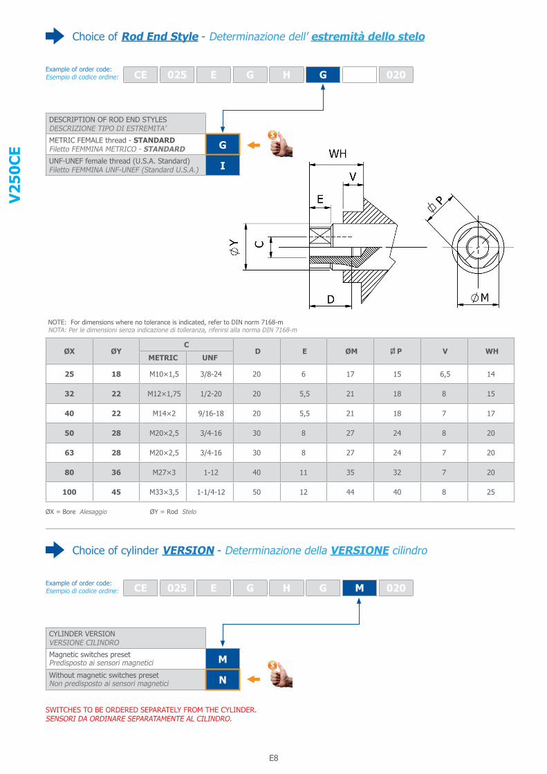
Choice of Rod End Style - Determinazione dell’ estremità dello stelo
Example of order code:Esempio di codice ordine:
ØX = Bore Alesaggio ØY = Rod Stelo
Choice of cylinder VERSION - Determinazione della VERSIONE cilindro
Example of order code:Esempio di codice ordine:
CE 025 E G H G M 020
DESCRIPTION OF ROD END STYLESDESCRIZIONE TIPO DI ESTREMITA’
METRIC FEMALE thread - STANDARDFiletto FEMMINA METRICO - STANDARD GUNF-UNEF female thread (U.S.A. Standard)Filetto FEMMINA UNF-UNEF (Standard U.S.A.) I
CE 025 E G H G M 020
CYLINDER VERSIONVERSIONE CILINDRO
Magnetic switches preset Predisposto ai sensori magnetici MWithout magnetic switches presetNon predisposto ai sensori magnetici N
ØX ØYC
D E ØM P V WH METRIC UNF
25 18 M10×1,5 3/8-24 20 6 17 15 6,5 14
32 22 M12×1,75 1/2-20 20 5,5 21 18 8 15
40 22 M14×2 9/16-18 20 5,5 21 18 7 17
50 28 M20×2,5 3/4-16 30 8 27 24 8 20
63 28 M20×2,5 3/4-16 30 8 27 24 7 20
80 36 M27×3 1-12 40 11 35 32 7 20
100 45 M33×3,5 1-1/4-12 50 12 44 40 8 25
SWITCHES TO BE ORDERED SEPARATELY FROM THE CYLINDER.SENSORI DA ORDINARE SEPARATAMENTE AL CILINDRO.
NOTE: For dimensions where no tolerance is indicated, refer to DIN norm 7168-mNOTA: Per le dimensioni senza indicazione di tolleranza, riferirsi alla norma DIN 7168-m
E8 E9
V25
0CE
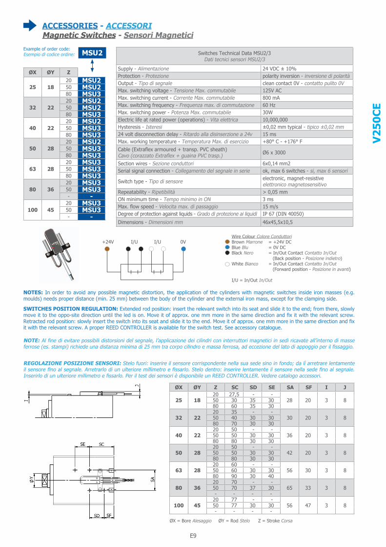
ACCESSORIES - ACCESSORIMagnetic Switches - Sensori Magnetici
Example of order code:Esempio di codice ordine:
Wire Colour Colore ConduttoriBrown Marrone = +24V DCBlue Blu = 0V DCBlack Nero = In/Out Contact Contatto In/Out (Back position - Posizione indietro)White Bianco = In/Out Contact Contatto In/Out (Forward position - Posizione in avanti)
I/U = In/Out In/Out
+24V I/U I/U 0V
MSU2 Switches Technical Data MSU2/3Dati tecnici sensori MSU2/3
Supply - Alimentazione 24 VDC ± 10% Protection - Protezione polarity inversion - inversione di polarità Output - Tipo di segnale clean contact 0V - contatto pulito 0V Max. switching voltage - Tensione Max. commutabile 125V AC Max. switching current - Corrente Max. commutabile 800 mA Max. switching frequency - Frequenza max. di commutazione 60 Hz Max. switching power - Potenza Max. commutabile 30W Electric life at rated power (operations) - Vita elettrica 10,000,000 Hysteresis - Isteresi ±0,02 mm typical - tipico ±0,02 mm 24 volt disconnection delay - Ritardo alla disinserzione a 24v 15 ms Max. working temperature - Temperatura Max. di esercizio +80° C - +176° F Cable (Extraflex armoured + transp. PVC sheath) Cavo (corazzato Extraflex + guaina PVC trasp.) Ø6 x 3000
Section wires - Sezione conduttori 6x0,14 mm2 Serial signal connection - Collegamento del segnale in serie ok, max 6 switches - si, max 6 sensori
Switch type - Tipo di sensore electronic, magnet-resistive elettronico magnetosensitivo
Repeatability - Ripetibilità > 0,05 mm ON minimum time - Tempo minimo in ON 3 ms Max. flow speed - Velocita max. di passaggio 15 m/s Degree of protection against liquids - Grado di protezione ai liquidi IP 67 (DIN 40050)
Dimensions - Dimensioni mm 46x45,5x10,5
ØX ØY Z
25 1820 MSU250 MSU280 MSU3
32 2220 MSU250 MSU280 MSU3
40 2220 MSU250 MSU380 MSU3
50 2820 MSU250 MSU380 MSU3
63 2820 MSU350 MSU380 MSU3
80 3620 MSU350 MSU3- -
100 4520 MSU350 MSU3- -
ØX ØY Z SC SD SE SA SF I J
25 1820 27,5 - -
28 20 3 850 30 35 3080 60 35 30
32 2220 35 - -
30 20 3 850 40 30 3080 70 30 30
40 2220 50 - -
36 20 3 850 50 30 3080 80 30 30
50 2820 50 - -
42 20 3 850 50 30 3080 80 30 30
63 2820 60 - -
56 30 3 850 60 30 3080 90 30 40
80 3620 70 - -
65 33 3 850 70 37 30- - - -
100 4520 77 - -
56 47 3 850 77 30 30- - - -
NOTES: In order to avoid any possible magnetic distortion, the application of the cylinders with magnetic switches inside iron masses (e.g. moulds) needs proper distance (min. 25 mm) between the body of the cylinder and the external iron mass, except for the clamping side.
NOTE: Al fine di evitare possibili distorsioni del segnale, l’applicazione dei cilindri con interruttori magnetici in sedi ricavate all’interno di masse ferrose (es. stampi) richiede una distanza minima di 25 mm tra corpo cilindro e massa ferrosa, ad eccezione del lato di appoggio per il fissaggio.
ØX = Bore Alesaggio ØY = Rod Stelo Z = Stroke Corsa
SWITCHES POSITION REGULATION: Extended rod position: insert the relevant switch into its seat and slide it to the end; from there, slowly move it to the oppo-site direction until the led is on. Move it of approx. one mm more in the same direction and fix it with the relevant screw. Retracted rod position: slowly insert the switch into its seat and slide it to the end. Move it of approx. one mm more in the same direction and fix it with the relevant screw. A proper REED CONTROLLER is available for the switch test. See accessory catalogue.
REGOLAZIONE POSIZIONE SENSORI: Stelo fuori: inserire il sensore corrispondente nella sua sede sino in fondo; da lì arretrare lentamente il sensore fino al segnale. Arretrarlo di un ulteriore millimetro e fissarlo. Stelo dentro: inserire lentamente il sensore nella sede fino al segnale. Inserirlo di un ulteriore millimetro e fissarlo. Per il test dei sensori è disponibile un REED CONTROLLER. Vedere catalogo accessori.
E10
V25
0CE
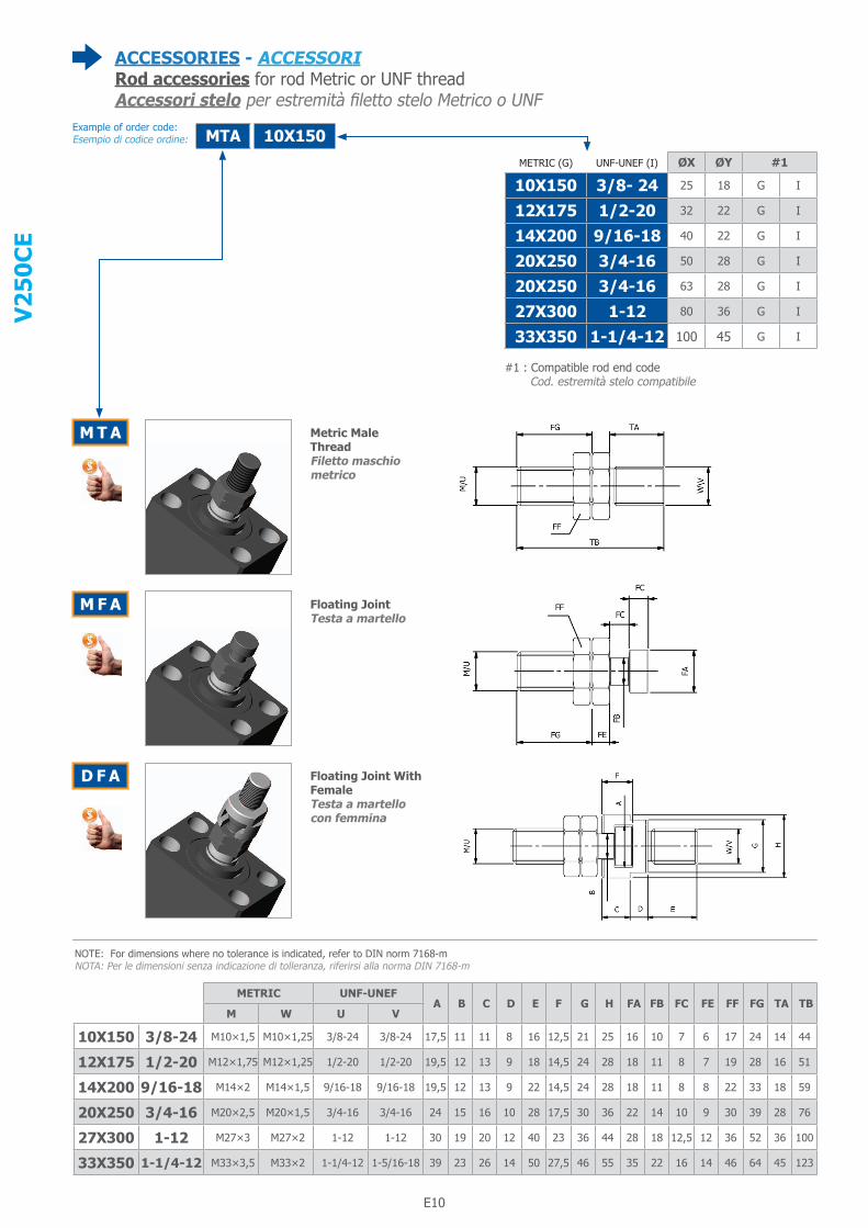
ACCESSORIES - ACCESSORIRod accessories for rod Metric or UNF threadAccessori stelo per estremità filetto stelo Metrico o UNF
Example of order code:Esempio di codice ordine:
Metric MaleThreadFiletto maschiometrico
Floating JointTesta a martello
Floating Joint WithFemaleTesta a martellocon femmina
MTA 10X150
M T A
M F A
D F A
METRIC (G) UNF-UNEF (I) ØX ØY #1
10X150 3/8- 24 25 18 G I
12X175 1/2-20 32 22 G I
14X200 9/16-18 40 22 G I
20X250 3/4-16 50 28 G I
20X250 3/4-16 63 28 G I
27X300 1-12 80 36 G I
33X350 1-1/4-12 100 45 G I
#1 : Compatible rod end code Cod. estremità stelo compatibile
METRIC UNF-UNEF A B C D E F G H FA FB FC FE FF FG TA TB
M W U V
10X150 3/8-24 M10×1,5 M10×1,25 3/8-24 3/8-24 17,5 11 11 8 16 12,5 21 25 16 10 7 6 17 24 14 44
12X175 1/2-20 M12×1,75 M12×1,25 1/2-20 1/2-20 19,5 12 13 9 18 14,5 24 28 18 11 8 7 19 28 16 51
14X200 9/16-18 M14×2 M14×1,5 9/16-18 9/16-18 19,5 12 13 9 22 14,5 24 28 18 11 8 8 22 33 18 59
20X250 3/4-16 M20×2,5 M20×1,5 3/4-16 3/4-16 24 15 16 10 28 17,5 30 36 22 14 10 9 30 39 28 76
27X300 1-12 M27×3 M27×2 1-12 1-12 30 19 20 12 40 23 36 44 28 18 12,5 12 36 52 36 100
33X350 1-1/4-12 M33×3,5 M33×2 1-1/4-12 1-5/16-18 39 23 26 14 50 27,5 46 55 35 22 16 14 46 64 45 123
NOTE: For dimensions where no tolerance is indicated, refer to DIN norm 7168-mNOTA: Per le dimensioni senza indicazione di tolleranza, riferirsi alla norma DIN 7168-m
E10 E11
V25
0CE
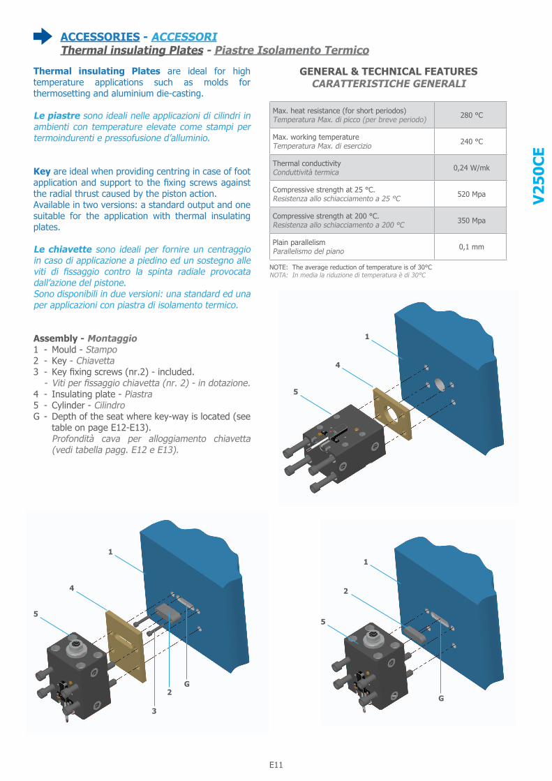
ACCESSORIES - ACCESSORIThermal insulating Plates - Piastre Isolamento Termico
Thermal insulating Plates are ideal for high temperature applications such as molds for thermosetting and aluminium die-casting.
Le piastre sono ideali nelle applicazioni di cilindri in ambienti con temperature elevate come stampi per termoindurenti e pressofusione d’alluminio.
Key are ideal when providing centring in case of foot application and support to the fixing screws against the radial thrust caused by the piston action.Available in two versions: a standard output and one suitable for the application with thermal insulating plates.
Le chiavette sono ideali per fornire un centraggio in caso di applicazione a piedino ed un sostegno alle viti di fissaggio contro la spinta radiale provocata dall’azione del pistone.Sono disponibili in due versioni: una standard ed una per applicazioni con piastra di isolamento termico.
Assembly - Montaggio1 - Mould - Stampo2 - Key - Chiavetta3 - Key fixing screws (nr.2) - included. - Viti per fissaggio chiavetta (nr. 2) - in dotazione.4 - Insulating plate - Piastra5 - Cylinder - CilindroG - Depth of the seat where key-way is located (see
table on page E12-E13). Profondità cava per alloggiamento chiavetta
(vedi tabella pagg. E12 e E13).
GENERAL & TECHNICAL FEATURES CARATTERISTICHE GENERALI
1
4
5
1
2
5
G
1
4
5
G2
3
Max. heat resistance (for short periodos) Temperatura Max. di picco (per breve periodo) 280 °C
Max. working temperature Temperatura Max. di esercizio 240 °C
Thermal conductivity Conduttività termica 0,24 W/mk
Compressive strength at 25 °C. Resistenza allo schiacciamento a 25 °C 520 Mpa
Compressive strength at 200 °C. Resistenza allo schiacciamento a 200 °C 350 Mpa
Plain parallelism Parallelismo del piano 0,1 mm
NOTE: The average reduction of temperature is of 30°CNOTA: In media la riduzione di temperatura è di 30°C
E12
V25
0CE
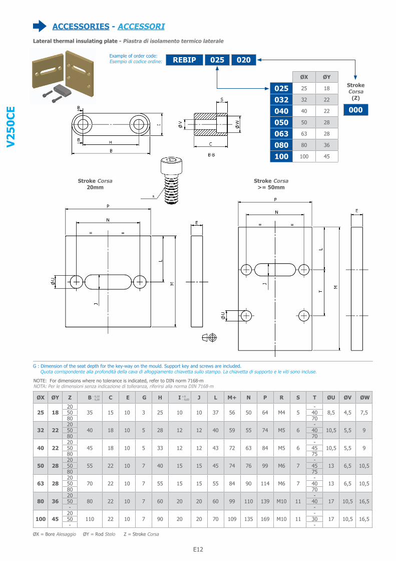
ACCESSORIES - ACCESSORI
Example of order code:Esempio di codice ordine:
Lateral thermal insulating plate - Piastra di isolamento termico laterale
Stroke Corsa20mm
Stroke Corsa>= 50mm
025REBIP 020
G : Dimension of the seat depth for the key-way on the mould. Support key and screws are included. Quota corrispondente alla profondità della cava di alloggiamento chiavetta sullo stampo. La chiavetta di supporto e le viti sono incluse.
ØX ØY
025 25 18
032 32 22
040 40 22
050 50 28
063 63 28
080 80 36
100 100 45
StrokeCorsa
(Z)
000
ØX ØY Z B C E G H I J L M+ N P R S T ØU ØV ØW
25 1820
35 15 10 3 25 10 10 37 56 50 64 M4 5-
8,5 4,5 7,550 4080 70
32 2220
40 18 10 5 28 12 12 40 59 55 74 M5 6-
10,5 5,5 950 4080 70
40 2220
45 18 10 5 33 12 12 43 72 63 84 M5 6-
10,5 5,5 950 4580 75
50 2820
55 22 10 7 40 15 15 45 74 76 99 M6 7-
13 6,5 10,550 4580 75
63 2820
70 22 10 7 55 15 15 55 84 90 114 M6 7-
13 6,5 10,550 4080 70
80 3620
80 22 10 7 60 20 20 60 99 110 139 M10 11-
17 10,5 16,550 40- -
100 4520
110 22 10 7 90 20 20 70 109 135 169 M10 11-
17 10,5 16,550 30- -
ØX = Bore Alesaggio ØY = Rod Stelo Z = Stroke Corsa
- 0,10 - 0,20
+ 0 - 0,03
NOTE: For dimensions where no tolerance is indicated, refer to DIN norm 7168-mNOTA: Per le dimensioni senza indicazione di tolleranza, riferirsi alla norma DIN 7168-m

E12 E13
V25
0CE
ACCESSORIES - ACCESSORI
Example of order code:Esempio di codice ordine:
Frontal thermal insulating plates - Piastra isolamento termico frontale
Key for lateral mounting - Chiavetta per fissaggio laterale
Example of order code:Esempio di codice ordine:
G : Dimension of the seat depth for the key-way on the mould. Quota corrispondente alla profondità della cava di alloggiamento chiavetta sullo stampo.
NOTE: Not available with frontal oil delivery « F »NOTA: Non disponibile con alimentazione olio frontale « F »
025REFIP ØX ØY
025 25 18
032 32 22
040 40 22
050 50 28
063 63 28
080 80 36
100 100 45
025REKW
ØX ØY B G I K
25 18 35 3 10 5
32 22 40 5 12 8
40 22 45 5 12 8
50 28 55 7 15 12
63 28 70 7 15 12
80 36 80 7 20 12
100 45 110 7 20 12
ØX ØY A D E F G ØR ØU
25 18 64 10 44 30 50 32 8,5
32 22 74 10 54 35 55 34 10,5
40 22 84 10 62 40 63 34 10,5
50 28 99 10 74 45 76 42 13
63 28 114 10 89 55 90 50 13
80 36 139 10 109 75 110 60 17
100 45 169 10 139 95 135 72 17
ØX ØY
025 25 18
032 32 22
040 40 22
050 50 28
063 63 28
080 80 36
100 100 45
- 0,10 - 0,20
+ 0 - 0,03
ØX = Bore Alesaggio ØY = Rod Stelo Z = Stroke Corsa
NOTE: For dimensions where no tolerance is indicated, refer to DIN norm 7168-mNOTA: Per le dimensioni senza indicazione di tolleranza, riferirsi alla norma DIN 7168-m
NOTE: For dimensions where no tolerance is indicated, refer to DIN norm 7168-mNOTA: Per le dimensioni senza indicazione di tolleranza, riferirsi alla norma DIN 7168-m

E14
V25
0CE
Example of order code:Esempio di codice ordine:
Type
Mod
ello
Cylin
der
bore
Ales
aggi
o ci
lindr
o
Artic
le C
ode
Codi
ce A
rtic
olo
Cylin
der
stro
keCo
rsa
cilin
dro
Addi
tiona
l set
cod
eIn
dica
zion
e d’
assi
eme
1
23
4
5
9 8 7 6
RE … 6010 A Rod seals kit - Serie guarnizioni stelo 6
RE … 6020 A Piston seals kit - Serie guarnizioni pistone 3
RE … 6030 FKM o-ring for integrated oil delivery - O-ring alimentazione integrata in FKM
RE … 0310 Rod cartridge without seals - Cartuccia stelo senza guarnizioni 5
RE … 0310 A Rod cartridge with seals - Cartuccia stelo con guarnizioni 5+6
RE … 6050 Permament Magnet Ring - Anello magnetico permanente 8
RE … 1520 A Non magnetic piston with seals - Pistone non magnetico con guarnizioni 3+4
RE … 1510 A Magnetic piston with seals - Pistone magnetico con guarnizioni 3+4+8
RE … 1120 … Rod with Female Metric Thread Rod End “G” - Stelo con estremità filetto femmina Metrico “G” 7
RE … 1121 … Rod with Female UNF Thread Rod End “I” - Stelo con estremità filetto femmina UNF (USA Standard) “I” 7
RE … 1530 A … Magnetic rod-piston group with Female Metric Thread Rod End “G” Gruppo stelo/pistone magnetico con estremità filetto femmina Metrico “G” 3+4+7+8
RE … 1531 A … Magnetic rod-piston group with Female UNF Thread Rod End (USA Standard) “I” Gruppo stelo/pistone magnetico con estremità filetto femmina UNF (USA Standard) “I” 3+4+7+8
RE … 1540 A … Non-magnetic rod-piston group with Female Metric Thread Rod End “G” Gruppo stelo/pistone normale con estremità filetto femmina Metrico “G” 3+4+7
RE … 1541 A … Non-magnetic rod-piston group with Female UNF Thread Rod End (USA Standard) “I” Gruppo stelo/pistone normale con estremità filetto femmina UNF (USA Standard) “I” 3+4+7
RE … 1930F … Body for clamping style “C”, frontal oil ports with O-Rings - Corpo fissaggio “C”, orifizi tipo O-Ring frontali
9
RE … 1930R … Body for clamping style “C”, back oil ports with O-Rings - Corpo fissaggio “C”, orifizi tipo O-Ring posteriori
RE … 1920M … Body for clamping style “E”, BSP right-positioned threaded holes - Corpo fissaggio “E”, orifizi filettati BSP lato destro
RE … 1920H … Body for clamping style “E”, BSP left-positioned threaded holes - Corpo fissaggio “E”, orifizi filettati BSP lato sinistro
RE … 1924M … Body for clamping style “E”, NPT right-positioned threaded holes - Corpo fissaggio “E”, orifizi filettati NPT lato destro
RE … 1924H … Body for clamping style “E”, NPT left-positioned threaded holes - Corpo fissaggio “E”, orifizi filettati NPT lato sinistro
RE … 1934E … Body for clamping style “E”, lateral oil ports with O-Ring - Corpo fissaggio “E”, orifizi tipo O-Ring laterali
RE … 1920D … Body for clamping style “E”, BSP right and left-positioned threaded holes Corpo fissaggio “E”, orifizi filettati BSP lato destro e sinistro
RE … 1924D … Body for clamping style “E”, NPT right and left-positioned threaded holes Corpo fissaggio “E”, orifizi filettati NPT lato destro e sinistro
RE … 6301 A … “Fixing Switch Screw each cylinder requires two of them Vite di fissaggio sensore, ogni cilindro ne richiede due” 2
MSU2 Multifunction switch - Interruttore completo1
MSU3 Multifunction switch - Interruttore completo
RE 025 6010 A
1 Double Magnetic Switch Doppio sensore magnetico2 Fixing Switch Screw, each cylinder requires two of them Vite di fissaggio sensore, ogni cilindro ne richiede due3 Piston seals - Guarnizioni pistone4 Piston - Pistone5 Rod Cartridge Cartuccia porta guarnizioni stelo6 Rod seals - Guarnizioni stelo7 Rod - Stelo8 Magnet Ring, for magnetic cylinder Anello magnetico, per cilindro magnetico9 Body - Corpo
Spare Parts - Ricambi

E14 E15
V25
0CE
Notes Note

®
www.vegacylinder.com