Thesis BinLIU New
192
Thèse présentée pour obtenir le grade de docteur de TELECOM ParisTech Spécialité : Informatique et Réseaux Bin LIU Mécanismes de handover inter système 3G-WiMAX. Etude des performances comparées d’une approche basée sur IP et d’une approche utilisant des protocoles radio de niveau 2 Soutenue le 4 Mai 2009 devant le jury composé de Philippe Godlewski Président Jean-Marie Bonnin Rapporteurs Ken Chen Philippe Bertin Examinateurs Jérôme Brouet Nadia Boukhatem Philippe Martins Directeur de thèse pastel-00005775, version 1 - 16 Nov 2010
-
Upload
ma-roua-abdelhafidh -
Category
Documents
-
view
30 -
download
2
Transcript of Thesis BinLIU New
Thèse
présentée pour obtenir le grade de docteur
de TELECOM ParisTech
Spécialité : Informatique et Réseaux
Bin LIU
Mécanismes de handover inter système 3G-WiMAX. Etude des performances comparées d’une approche
basée sur IP et d’une approche utilisant des protocoles radio de niveau 2
Soutenue le 4 Mai 2009 devant le jury composé de
Philippe Godlewski Président
Jean-Marie Bonnin Rapporteurs
Ken Chen
Philippe Bertin Examinateurs
Jérôme Brouet
Nadia Boukhatem
Philippe Martins Directeur de thèse
past
el-0
0005
775,
ver
sion
1 -
16 N
ov 2
010

past
el-0
0005
775,
ver
sion
1 -
16 N
ov 2
010
Dissertation
submitted in partial fulfillment of the requirements
for the Ph.D degree in Computer Science of
École Nationale Supérieure des Télécommunications Speciality: Computer Science and Network
Bin LIU
Design and performance evaluation of inter-RAT handover mechanisms for
WiMAX and 3G-LTE networks
4th May 2009, Dissertation committee:
Philippe Godlewski President
Jean-Marie Bonnin Reviewer
Ken Chen
Philippe Bertin Examiner
Jérôme Brouet
Nadia Boukhatem
Philippe Martins Thesis Advisor
past
el-0
0005
775,
ver
sion
1 -
16 N
ov 2
010

past
el-0
0005
775,
ver
sion
1 -
16 N
ov 2
010

To my parents and little sister,
to my advisor, and
to all my beloved friends.
past
el-0
0005
775,
ver
sion
1 -
16 N
ov 2
010

past
el-0
0005
775,
ver
sion
1 -
16 N
ov 2
010

Design and Performance Evaluation of Inter-RAT Handover Mechanisms for WiMAX and 3G-LTE Networks
Acknowledgements
A long road to success to a Ph.D degree in France could never be happened without these people who have given me guidance, encouragement, support and great help.
Firstly, I am deeply grateful to my advisor Prof. Philippe Martins for his invaluable guidance and encouragement throughout my three years’ study. Whenever I met research problems, he always encouraged me to overcome them and gave me much confidence about the future. Furthermore, he also taught me how to keep good relationships with colleagues and others.
My special gratefulness goes to Mr. Philippe Bertin, Mr. Rodolphe Legouable and Mr. Abed Ellatif Samhat at France Telecom. During our fruitful cooperation, they have given me so many precious comments for every paper I wrote, and their discussions directly help the development of this thesis.
I would like to thank sincerely Prof. Daniel Kofman. Without his help, I could not have this great opportunity to do my research work in this prestigious engineer school: TELECOM ParisTech. I am also grateful to Prof. Philippe Godlewski and Prof. Marceau Coupechoux for their generosity, helpful advice and comments.
I am tremendously indebted to Prof. Nadia Boukhatem, who accepted the most difficult work of examining my work written in this dissertation.
I thank to sincerely my committee members: Prof. Jean Marie Bonnin, Prof. Ken Chen, Dr. Jérôme Brouet, Prof. Philippe Godlewski, Prof. Nadia Boukhatem, Dr. Philippe Bertin for reviewing my thesis and agreeing to serve in my committee.
My gratitude also extends to all my close friends and colleagues for their kindness and fruitful discussion, especially Dr. Lin CHEN, Dr. Chunyang YIN, Dr. Xiaoyun XUE. I am especially grateful to my close friends: Liang QIAN, Bei WANG, Ronghui ZHU, Shuren YU. I am also very thankful to Miss Soussou, our lovely department secretary, for her help when I returned from several international conferences.
I give my deepest thanks to my beloved parents and little sister, for their infinite love, encouragement, and spirit support.
past
el-0
0005
775,
ver
sion
1 -
16 N
ov 2
010

past
el-0
0005
775,
ver
sion
1 -
16 N
ov 2
010

Design and Performance Evaluation of Inter-RAT Handover Mechanisms for WiMAX and 3G-LTE Networks
Résumé
Dans les futurs réseaux mobiles, différentes technologies d’accès radio, telles que GSM, UMTS, WiMAX, WIFI coexisteront. Pour réaliser un handover vertical sans couture (handover inter-RAT) entre ces technologies, des architectures d’interconnexion et des moyens pour gérer le handover inter-RAT sont proposés. Afin de proposer une solution efficace, nous allons d’abord analyser la solution « Fast MIPv6 (FMIPv6) ». Les analyses numériques démontrent les défauts de FMIPv6 et les exigences de handover inter-RAT. En considérant une architecture de couplage intégré (integrated coupling), nous proposons une nouvelle sous-couche commune d’interconnexion (IW sublayer) au niveau 2 sur le RNC (Radio Network Controller) et le MS (Mobile Station) pour offrir un handover inter-RAT sans couture entre les systèmes UMTS et WiMAX. Cette sous-couche IW permet d'éliminer la perte des paquets et de réduire la latence de handover. Ces paramètres sont des éléments importants communs à la plupart des scénarios de handover inter-RAT. Cette sous-couche IW est également étendue à l'architecture de couplage serré (tight coupling).
En outre, deux types de solution basées sur TCP Proxy, qui utilisent la sous-couche IW, sont également introduites sur le RNC pour résoudre deux problèmes rencontrés avec l’utilisation du trafic TCP dans un handover inter-RAT: le « BDP mismatch » et le « spurious RTO (Retransmission TimeOut) ». Le premier type de solution basé sur TCP Proxy est adapté aux scénarios où le handover est fréquent, tandis que le deuxième type de solution basé sur TCP Proxy est conçu pour les scénarios où le handover est occasionnel. Par rapport aux autres solutions de handover vertical, les résultats de simulation montrent que notre deuxième type de solution a le mérite de maintenir la pile de protocole TCP existante inchangée.
Les solutions classiques de handover inter-RAT sont généralement réalisées au niveau 2 ou au-dessus, parce qu’il n’y a pas de module commun à la couche physique pour les deux systèmes, ou en raison de la distance géographique des systèmes. Mais pour les futurs systèmes LTE et WiMAX dans à l'architecture « integrated coupling », ce n’est pas le cas, parce qu’ils ont un certain nombre de techniques physiques communes, telles que MIMO et OFDM. Deux modules nommés « precoder » et « combiner » sont proposés respectivement sur les BSs (stations de base) et sur le MS au niveau physique afin d’exploiter au maximum la diversité des deux réseaux d’accès radio et de réaliser un « soft » handover inter-RAT. Ce « soft » handover inter-RAT au niveau physique est entièrement nouveau à notre connaissance.
past
el-0
0005
775,
ver
sion
1 -
16 N
ov 2
010

Design and Performance Evaluation of Inter-RAT Handover Mechanisms for WiMAX and 3G-LTE Networks
past
el-0
0005
775,
ver
sion
1 -
16 N
ov 2
010
Design and Performance Evaluation of Inter-RAT Handover Mechanisms for WiMAX and 3G-LTE Networks
Abstract
In future mobile networks, different radio access technologies, such as GSM, UMTS, WiMAX, WIFI, will coexist. In order to realize a seamless vertical handover (inter-RAT handover) between these technologies, a variety of interworking architectures and inter-RAT handover mobility managements have been proposed. To propose an efficient inter-RAT handover solution, we first analyze a typical Layer 3 Mobile IPv6 (MIPv6) solution- Fast MIPv6 (FMIPv6). The numerical analysis demonstrates its drawbacks of uncertain handover latency and possible packet losses, and reveals the requirements for a seamless inter-RAT handover. Then, based on an integrated coupling architecture, we propose a novel common interworking sublayer (IW sublayer) at Layer 2 on RNC (Radio Network Controller) and MS (Mobile Station) to provide a seamless inter-RAT handover between UMTS and WiMAX systems. This IW sublayer solution focuses on eliminating packet loss and reducing handover latency, which are common challenges for most inter-RAT handover scenarios. This IW sublayer solution is also applied to the tight coupling architecture.
In addition, two kinds of TCP Proxy, which interacts with the IW sublayer, are also introduced on the RNC in the integrated coupling architecture to resolve two typical inter-RAT handover problems for TCP traffics: BDP mismatch and spurious RTO. Because it is needed to periodically feed back ZWA (Zero Window Advertisement) messages to TCP sender to freeze its retransmission timer and congestion window, the first kind of TCP Proxy is suitable for frequent handover scenarios. In the second kind of TCP Proxy, the ACK Delaying and the explicit window notification mechanisms make it suitable for occasional handover scenarios. Compared with other vertical handover solutions, our second TCP Proxy scheme with cross-layer mechanism has the merits of keeping existing TCP protocol stacks unchanged.
All the conventional inter-RAT handover solutions are realized at Layer 2 or above due to the impossibility of a common module at physical layer and the geographical distance of source and target systems. But for the future LTE and WiMAX systems in the integrated coupling architecture, this is not the case, because they have some common physical techniques such as MIMO and OFDM. Two common modules named precoder and combiner are proposed respectively on BSs (Base Stations) and on MS at physical layer to exploit the maximum diversity of two RATs and to realize soft inter-RAT handover. This soft inter-RAT handover physical scheme is totally new to the best of our knowledge.
past
el-0
0005
775,
ver
sion
1 -
16 N
ov 2
010

past
el-0
0005
775,
ver
sion
1 -
16 N
ov 2
010
Design and Performance Evaluation of Inter-RAT Handover Mechanisms for WiMAX and 3G-LTE Networks
Table of Contents
Chapter 0 Résumé.................................................................................................................... 24 0.1 Contexte et Motivations.............................................................................................................24 0.1.1 Gestion de Handover Vertical ...........................................................................................................24 0.1.2 L’Architecture d’Interconnexion .....................................................................................................25 0.1.3 Problèmes Spécifiques de TCP .........................................................................................................26
0.2 Contributions ................................................................................................................................27 0.2.1 Handover Inter-‐RAT à la Couche Trois – Analyse de la Mode d’Opération FMIPv6 .28 0.2.2 Handover Inter-‐RAT à la Couche Deux – la Solution Sous-‐couche IW ............................36 0.2.3 Handover Inter-‐RAT à la Couche Quatre -‐ TCP Proxy ............................................................49 0.2.4 Handover Inter-‐RAT à la Couche Une – un Schéma du Soft Handover Inter-‐RAT à la Couche Physique................................................................................................................................................52
Chapter 1 Introduction .......................................................................................................... 56 1.1 Background and Motivation ....................................................................................................56 1.1.1 Vertical Handover Management ......................................................................................................56 1.1.2 Interworking Architecture.................................................................................................................57 1.1.3 TCP Specific Problems..........................................................................................................................59
1.2 Contributions ................................................................................................................................59 1.3 Organization of the Thesis........................................................................................................60
Chapter 2 Vertical Handover at Layer Three.................................................................. 63 2.1 Mobile IP and Its Extensions....................................................................................................64 2.1.1 Introduction..............................................................................................................................................64 2.1.2 Protocol Overview .................................................................................................................................64 2.1.3 Mobile IP Handover Performance Evaluation ...........................................................................66 2.1.4 Cross-‐Layer Triggers ............................................................................................................................71 2.1.5 Conclusion .................................................................................................................................................73
2.2 FMIPv6 Timing Analysis............................................................................................................74 2.2.1 The Timing Analysis of UDP Traffics .............................................................................................74 2.2.2 The Timing Analysis of TCP Traffics ..............................................................................................79 2.2.3 Numerical Analysis................................................................................................................................82 2.2.4 Network Simulation Analysis............................................................................................................90 2.2.5 Hybrid Operation Mode.......................................................................................................................94 2.2.6 Conclusion.................................................................................................................................................97
2.3 Conclusion......................................................................................................................................97 Chapter 3 Inter-‐RAT Handover at Layer Two...............................................................100 3.1 Cell Reselection and Handover in GSM/GPRS/UMTS [35-‐40][42-‐46]..................... 101 3.1.1 Cell Reselection and intra-‐RAT Handover in GSM/GPRS [36][39][43][44][45][46]................................................................................................................................................................................ 101 3.1.2 Inter-‐RAT Handover Between GSM/GPRS and UMTS [36][39][40][41][43][45][46]................................................................................................................................................................................ 103 3.1.3 Conclusion.............................................................................................................................................. 106
3.2 Inter-‐RAT Handover between UMTS and WiMAX in Integrated Coupling Architecture....................................................................................................................................... 106 3.2.1 Context Transfer.................................................................................................................................. 107 3.2.2 IW Sublayer ........................................................................................................................................... 109 3.2.3 Simulation Environment.................................................................................................................. 117
past
el-0
0005
775,
ver
sion
1 -
16 N
ov 2
010

14 Contents
Design and Performance Evaluation of Inter-RAT Handover Mechanisms for WiMAX and 3G-LTE Networks
3.2.4 Simulation Results .............................................................................................................................. 118 3.2.5 Conclusion.............................................................................................................................................. 120
3.3 Inter-‐RAT Handover between UMTS and WiMAX in Tight Coupling Architecture 121 3.3.1 The IW Sublayer in the Tight Coupling Architecture........................................................... 122 3.3.2 Simulation Environment and Results......................................................................................... 128 3.3.3 Conclusion.............................................................................................................................................. 132
3.4 Conclusion................................................................................................................................... 132 Chapter 4 TCP Proxy for Inter-‐RAT Handover .............................................................134 4.1 TCP Specific Handover Problems........................................................................................ 134 4.1.1 Receiver-‐centric Approaches......................................................................................................... 135 4.1.2 Network-‐centric Approaches......................................................................................................... 135
4.2 Frequent Handover Scenario................................................................................................ 136 4.2.1 TCP Proxy Description...................................................................................................................... 136 4.2.2 A TCP Proxy Example ........................................................................................................................ 138 4.2.3 TCP Proxy Algorithm In NS2 .......................................................................................................... 139 4.2.4 Signaling and Primitive between IW and TCP Proxy........................................................... 141 4.2.5 Simulation Environment and Results......................................................................................... 142 4.2.6 Conclusion.............................................................................................................................................. 146
4.3 Occasional Handover Scenario ............................................................................................ 147 4.3.1 TCP Proxy Description...................................................................................................................... 147 4.3.2 An Example of TCP Proxy Working Procedure ...................................................................... 149 4.3.3 Signaling and Primitives between IW and TCP Proxy......................................................... 149 4.3.4 ACK Delaying in TCP Proxy............................................................................................................. 150 4.3.5 Explicit Window Notification (EWN) in TCP Proxy.............................................................. 152 4.3.6 Simulation Results .............................................................................................................................. 152 4.3.7 Conclusion.............................................................................................................................................. 155
4.4 Conclusion................................................................................................................................... 156 Chapter 5 Inter-‐RAT Handover at Layer One ...............................................................158 5.1 Introduction ............................................................................................................................... 158 5.2 Transceiver Architecture....................................................................................................... 159 5.2.1 Transmitter............................................................................................................................................ 159 5.2.2 Receiver................................................................................................................................................... 161
5.3 Frame, Synchronization and Signaling.............................................................................. 162 5.3.1 MIMO-‐OFDMA....................................................................................................................................... 162 5.3.2 Frame Synchronization .................................................................................................................... 163 5.3.3 Coarse Slot Synchronization........................................................................................................... 164 5.3.4 Signaling Procedure ........................................................................................................................... 164
5.4 Numerical Analysis .................................................................................................................. 166 5.4.1 System Model........................................................................................................................................ 166 5.4.2 Slot Allocation....................................................................................................................................... 167 5.4.3 Numerical Results ............................................................................................................................... 169
5.5 Conclusion................................................................................................................................... 170 Chapter 6 Conclusion............................................................................................................171 6.1 Contributions ............................................................................................................................. 171
6.1.1 FMIPv6 Timing Analysis................................................................................................................... 172 6.1.2 IW Sublayer in Integrated Coupling and Tight Coupling Architectures ...................... 172
past
el-0
0005
775,
ver
sion
1 -
16 N
ov 2
010
Contents
Design and Performance Evaluation of Inter-RAT Handover Mechanisms for WiMAX and 3G-LTE Networks
15
6.1.3 TCP Proxy for Frequent and Occasional Handover Scenarios ......................................... 173 6.1.4 Soft Inter-‐RAT handover at Physical Layer.............................................................................. 173
6.2 Perspectives ............................................................................................................................... 173 6.2.1 Physical Layer Soft Inter-‐RAT Handover Performance Evaluation............................... 173 6.2.2 Retransmission Mechanism at IP layer ..................................................................................... 173 6.2.3 Multihoming at Layer Two.............................................................................................................. 175
APPENDIX A NS2 Simulation Platform ........................................................................176 A.1 NS2 Multi-‐RAT Mobile Node Model................................................................................. 176 A.1.1 Simulation Requirements ................................................................................................................... 176 A.1.2 Extended Mobile Nodes ....................................................................................................................... 176 A.1.3 UMTS/WiMAX Network Entity Models......................................................................................... 176 A.1.4 Main Functions of Protocol Stacks .................................................................................................. 178 A.2 A Multi-‐channel Scheme..................................................................................................... 178 A.2.1 UMTS Channel Configuration Script............................................................................................... 178 A.2.2 WiMAX Channel Configuration Script............................................................................................ 179 A.2.3 Script of Creating a Multiple-‐Channel Mobile Node ................................................................ 180 A.2.4 Entity Assembly Script ......................................................................................................................... 180 A.3 A Signaling Procedure Example....................................................................................... 181
past
el-0
0005
775,
ver
sion
1 -
16 N
ov 2
010

Design and Performance Evaluation of Inter-RAT Handover Mechanisms for WiMAX and 3G-LTE Networks
List of Figures
Figure 0-1: L’Architecture des réseaux du « loose coupling » ..........................................................25 Figure 0-2: Les architectures des réseaux du « integrated coupling » et du « tight coupling ».........26 Figure 0-3: Timing diagramme de la mode prédictive I ....................................................................29 Figure 0-4: Timing diagramme de la mode prédictive II...................................................................30 Figure 0-5: (a) La latence de handover avec le temps varié ; (b) Cout de paquet avec le temps
varié .................................................................................................................................31 Figure 0-6: (a) La TCP latence de handover vs. le temps du déclencheur; (b) la TCP latence de
handover vs. la latence de transmission par saut entre le PAR et le NAR en mode réactif.......33 Figure 0-7: Topologie pour la simulation du réseau ..........................................................................34 Figure 0-8: Comparaison de la fenêtre de congestion TCP ...............................................................35 Figure 0-9: Fonctionnement de la sous-couche IW du « integrated coupling » ................................37 Figure 0-10: Pile protocolaire dans le plan d’utilisateur pour une architecture « integrated coupling
»..................................................................................................................................................38 Figure 0-11: Pile protocolaire dans le plan de contrôle pour une architecture « integrated coupling »
....................................................................................................................................................39 Figure 0-12: Les mécanismes IW ARQ et R-LLC - un exemple d'évolution temporelle..................40 Figure 0-13: Procédure de signalisation handover de l’UMTS au WiMAX .....................................41 Figure 0-14: Procédure de signalisation de handover du WiMAX à l’UMTS .................................42 Figure 0-15: Fonctionnement de la sous-couche IW du « tight coupling » .......................................43 Figure 0-16: Pile protocolaire dans le plan d’utilisateur pour l’architecture « tight coupling »........44 Figure 0-17: Pile protocolaire dans le plan de contrôle pour l’architecture « tight coupling » .........44 Figure 0-18: Procédure de signalisation de handover de l’UMTS au WiMAX.................................45 Figure 0-19: Procédure de signalisation de handover du WiMAX à l’UMTS ..................................46 Figure 0-20: La topologie de la simulation: (a) « integrated coupling »; (b) « tight coupling » .......47 Figure 0-21: Fenêtre de congestion TCP dans un scenario « integrated coupling »: (a) UMTS-
>WiMAX; (b) WiMAX->UMTS...............................................................................................47 Figure 0-22: Fenêtre de congestion TCP dans un scenario « tight coupling »: (a) UMTS->WiMAX;
(b) WiMAX->UMTS .................................................................................................................48 Figure 0-23: TCP Proxy dans l’architecture « integrated coupling » ................................................49 Figure 0-24: Un exemple du mécanisme TCP Proxy ........................................................................50 Figure 0-25: La variation du TCP RTO à l’émetteur TCP ................................................................51 Figure 0-26: L’architecture « integrated coupling » ..........................................................................52 Figure 0-27: La structure des blocs du transmetteur dans le BS........................................................53 Figure 0-28: La structure des blocs du récepteur dans le MS............................................................54 Figure 0-29: La structure de trame pour le « soft » handover inter-RAT..........................................55 Figure 1-1: Loose coupling network architecture .............................................................................58 Figure 1-2: Integrated and tight coupling network architectures ......................................................58 Figure 2-1: Layer 3 handover with Layer 2 triggers [23] .................................................................72 Figure 2-2: Timing diagram of predictive mode I. ............................................................................76 Figure 2-3: Timing diagram of predictive mode II. ..........................................................................77 Figure 2-4: Timing diagram of reactive mode. .................................................................................79 Figure 2-5: Timing diagram of a TCP connection in predictive mode..............................................80 Figure 2-6: Timing diagram of a TCP connection in reactive mode ................................................82 Figure 2-7: a) handover latency with varying time ; b) Packet Cost with varying time 83 Figure 2-8: Timing relation when LGD is issued ..............................................................................84
past
el-0
0005
775,
ver
sion
1 -
16 N
ov 2
010

Design and Performance Evaluation of Inter-RAT Handover Mechanisms for WiMAX and 3G-LTE Networks
17
Figure 2-9: a) Handover latency comparison of predictive and reactive modes; b) The influence of mobility on handover latency (eta=2) .............................................................................................86
Figure 2-10: The influence of mobility on handover latency: (a) eta=5; (b) eta=22 ..................................86 Figure 2-11: a) TCP handover latency with varying triggering timer; b) TCP handover latency with
varying transmission latency per hop between PAR and NAR in reactive mode......................88 Figure 2-12: The relations between handover latency and throughput degradation time when
RTO=0.5s...................................................................................................................................89 Figure 2-13: Network Simulation Topology......................................................................................90 Figure 2-14: TCP segment number comparison of FMIP (link layer handover latency: 0.1sec and
0.25sec) ......................................................................................................................................91 Figure 2-15: TCP congestion window comparison............................................................................92 Figure 2-16: TCP segment number comparison between FMIP (link layer handover 0.1sec) and
MIP (link layer handover 0.25sec).............................................................................................93 Figure 2-17: a) Call drop rate with the variation of wired network transmission delay; b) Average
packet cost with the variation of wired network transmission delay .........................................96 Figure 3-1: System Information for Inter-RAT cell reselection, measurement and handover in GSM
..................................................................................................................................................104 Figure 3-2: System Information Blocks for Inter-RAT cell re-selection, measurement and handover
in UMTS ..................................................................................................................................105 Figure 3-3: IW sublayer working mechanism of integrated coupling .............................................110 Figure 3-4: User plane protocol stacks in integrated coupling architecture ....................................111 Figure 3-5: Control plane protocol stacks in integrated coupling architecture ................................111 Figure 3-6: Signaling procedure of handover from UMTS to WiMAX ..........................................112 Figure 3-7: Signaling procedure of handover from WiMAX to UMTS ..........................................114 Figure 3-8: IW block sub-header format..........................................................................................115 Figure 3-9: IW ARQ and R-LLC: a example of time evolution ......................................................116 Figure 3-10: Simulation topology ....................................................................................................117 Figure 3-11: TCP segment number comparison (umts->wimax, sender side) ................................118 Figure 3-12: (a) TCP congestion window; (b) average throughput (Kbit/s), (umts->wimax).........119 Figure 3-13: TCP segment number comparison (wimax->umts, sender side) ................................121 Figure 3-14: (a) TCP congestion window; (b) average throughput (Kbit/s). (wimax->umts).........121 Figure 3-15: IW sublayer working mechanism of tight coupling....................................................122 Figure 3-16: User plane protocol stacks of tight coupling architecture ...........................................123 Figure 3-17: Control plane protocol stacks of tight coupling architecture ......................................124 Figure 3-18: Signaling procedure of the handover from UMTS to WiMAX ..................................126 Figure 3-19: Signaling procedure of the handover from WiMAX to UMTS ..................................127 Figure 3-20: Simulation topology ....................................................................................................129 Figure 3-21: TCP segment number comparison (umts->wimax, sender side) ................................130 Figure 3-22: (a) TCP congestion window; (b) average throughput (Kbit/s), (umts->wimax).........130 Figure 3-23: TCP segment number comparison (wimax->umts, sender side) ................................131 Figure 3-24: (a) TCP congestion window; (b) average throughput (Kbit/s) (wimax->umts)..........132 Figure 4-1: TCP Proxy in integrated coupling architecture .............................................................136 Figure 4-2: A TCP Proxy example ..................................................................................................139 Figure 4-3: Interaction between IW sublayer and TCP Proxy.........................................................141 Figure 4-4: TCP segment number comparison (wimax->umts, sender side, a=1.5, Qt=25, PDCP
queue length 25, UMTS data rate 64kb/s) ...............................................................................143 Figure 4-5: TCP congestion window (left figure), and average goodput (in kbit/s, right figure)
(wimax->umts, a=1.5 Qt=25, UMTS data rate 64kb/s) ...........................................................144 Figure 4-6: The variation of local queue length and advertised window size when UMTS data rate
changes (a=1.5, Qt=25, PDCP queue length 25) ....................................................................145
past
el-0
0005
775,
ver
sion
1 -
16 N
ov 2
010

18
Design and Performance Evaluation of Inter-RAT Handover Mechanisms for WiMAX and 3G-LTE Networks
Figure 4-7: The variation of local queue length and advertised window size when PDCP queue length changes (a=1.5, Qt=25, UMTS data rate 64kb/s) ........................................................146
Figure 4-8: An example of TCP Proxy working mechanism...........................................................149 Figure 4-9: Cross-layer interactions between the IW sublayer and the TCP Proxy ........................150 Figure 4-10: The variation of local queue length and advertised window size (UMTS data rate
64Kb/s, local queue length 35 after handover) ........................................................................153 Figure 4-11: The variation of RTO in TCP sender (UMTS data rate 64Kb/s, local queue length 35
after handover) .........................................................................................................................154 Figure 4-12: The influence of TCP Proxy target queue length on ACK Delaying phase duration .154 Figure 4-13: The TCP segment sequence number vs. time (UMTS data rate 64Kb/s, local queue
length 35 after handover) .........................................................................................................155 Figure 5-1: A typical integrated coupling architecture ....................................................................160 Figure 5-2: The block structure of the transceiver on the base stations...........................................161 Figure 5-3: The block structure of the transceiver on a MS ............................................................161 Figure 5-4: The frame structure for the soft inter-RAT handover ...................................................163 Figure 5-5: The signaling procedure of the soft inter-RAT handover .............................................165 Figure 5-6: (a) Slot allocation of users vs. number of iterations; (b) Average outage probability vs.
handover users..........................................................................................................................169 Figure A-1: The extended NS2 mobile node model for an integrated RNC or multi-RAT MS......177 Figure A-2: Configuration of UMTS channel..................................................................................179 Figure A-3: Configuration of WiMAX channel ..............................................................................179 Figure A-4: Create a multiple-channel mobile node.......................................................................180 Figure A-5: Add-interface-multi{} function...................................................................................180 Figure A-6: Assembly effect of the add-interface-multi{} function...............................................181 Figure A-7: 802.16e handover procedure (MS initiated)................................................................182
past
el-0
0005
775,
ver
sion
1 -
16 N
ov 2
010

Design and Performance Evaluation of Inter-RAT Handover Mechanisms for WiMAX and 3G-LTE Networks
19
List of Tables
Table 2.1: List of vertical handover latency ......................................................................................68 Table 2.2: List of Layer 3 handover latency ......................................................................................71 Table 3.1 Simulation Parameters .....................................................................................................117
past
el-0
0005
775,
ver
sion
1 -
16 N
ov 2
010

20
Design and Performance Evaluation of Inter-RAT Handover Mechanisms for WiMAX and 3G-LTE Networks
Acronyms
3GPP The 3rd Generation Partnership Project
AN Access Network
AP Access Point
AR Access Router
ARP Address Resolution Protocol
BCCH Broadcast Control Channel
BDP Bandwidth Delay Product
BS Base Station
BSIC Base Station Identity Code
BSS Base Station Subsystem
BSC Base Station Controller
BCCH Broadcast Control Channel
CPICH Common Pilot Channel
CoA Care-of-Address
CBR Constant Bit Rate
CCN Cell Change Notification
CN Correspondent Node
DAD Duplication Address Detection
DCD Downlink Channel Descriptor
DCH Dedicated Channel
DL-MAP Downlink Map
DHCP Dynamic Host Configuration Protocol
DSR Dynamic Source Routing
DSDV Destination Sequence Distance Vector
EDGE Enhanced Data rates for GSM Evolution
EGC Equal Gain Combining
EGPRS Enhanced General Packet Radio Service
eNB evolved Node B
FA Foreign Agent
FBACK Fast Binding Acknowledge
FBU Fast Binding Update
FDD Frequency Division Duplex
past
el-0
0005
775,
ver
sion
1 -
16 N
ov 2
010
Design and Performance Evaluation of Inter-RAT Handover Mechanisms for WiMAX and 3G-LTE Networks
21
FMIP Fast Mobile IP
FNA Fast Neighbor Advertisement
FNAACK Fast Neighbor Advertisement Acknowledgment
FTP File Transfer Protocol
GFA Gateway Foreign Agent
GERAN GSM/EDGE Radio Access Network
GSM Global System for Mobile Communications
GPRS General Packet Radio Service
GGSN Gateway GPRS Support Node
HA Home Agent
HACK Handover Acknowledge
HI Handover Initiate
HMIP Hierarchical Mobile IP
IETF Internet Engineering Task Force
LCoA On-Link Care-of-Address
L2 Layer 2
L2-MT Layer 2 Mobile Trigger
L2-ST Layer 2 Source Trigger
L2-TT Layer 2 Target Trigger
L2-LU Layer 2 Link Up Trigger
L2-LD Layer 2 Link Down Trigger
L3 Layer 3
IP Internet Protocol
MAC Medium Access Control
MAP Mobility Anchor Point
MBWA Mobile Broadband Wireless Access
MIMO Multi-Input Multi-Output
MME/S-GW Mobility Management Entity/Serving GateWay
MN Mobile Node
MRC Maximum Ratio Combining
MS Mobile Station
NAI Network Access Identifier
NAR New Access Router
NAT Network Address Translation
past
el-0
0005
775,
ver
sion
1 -
16 N
ov 2
010
22
Design and Performance Evaluation of Inter-RAT Handover Mechanisms for WiMAX and 3G-LTE Networks
NCoA Next Care-of-Address
nFA New Foreign Agent
NLCoA New Link Care-of-Address
oFA Old Foreign Agent
OFDM Orthogonal Frequency-Division Multiplexing
PACCH Packet Associated Control Channel
PAR Previous Access Router
PBCCH Packet Broadcast Control Channel
PCH Paging Channel
PCoA Previous Care-of-Address
PDCP Packet Data Convergence Protocol
PDP Packet Data Protocol
PDU Packet Data Unit
PFC Packet Flow Context
PLCoA Previous Link Care-of-Address
PLMN Public Land Mobile Network
PrRtAdv Proxy Router Advertisement
PRACH Packet Random Access Channel
PRB Physical Resource Block
PS Packet Switch
RACH Random Access Channel
RtAdv Router Advertisements
RCoA Regional Care-of-Address
RtSolPr Router Solicitation for Proxy Advertisement
RAB Radio Access Bearer
RACH Random Access Channel
RAT Radio Access Technology
RLC Radio Link Control
RNC Radio Network Controller
RNS Radio Network Subsystem
RRC Radio Resource Control
RSSI Received Signal Strength Indicator
RTO Retransmission TimeOut
SCH Synchronization Channel
past
el-0
0005
775,
ver
sion
1 -
16 N
ov 2
010
Design and Performance Evaluation of Inter-RAT Handover Mechanisms for WiMAX and 3G-LTE Networks
23
SCTP Stream Control Transmission Protocol
SDU Service Data Unit
SI System Information
SIB System Information Block
SINR Signal-to-Noise-and-Interference-Ratio
SIP Session Initiation Protocol
SHREP Seamless Handoff Request
SHIN Seamless Handoff Initiate
SGSN Serving GPRS Support Node
SR ARQ Selective Repeat ARQ
SRNS Service Radio Network Subsystem
TBF Temporary Block Flow
TCP Transmission Control Protocol
TORA Temporally Ordered Routing Protocol
UCD Uplink Channel Descriptor
UL-MAP Uplink Map
UMTS Universal Mobile Telecommunications System
URA UTRAN Registration Area
UTRA UMTS Terrestrial Radio Access
UTRAN UMTS Terrestrial Radio Access Network
VoIP Voice over IP
WCDMA Wideband Code Division Multiple Access
WiMAX Worldwide Interoperability for Microwave Access
WWAN Wireless Wide-area Access Network
WLAN Wireless Local-area Access Network
past
el-0
0005
775,
ver
sion
1 -
16 N
ov 2
010
Design and Performance Evaluation of Inter-RAT Handover Mechanisms for WiMAX and 3G-LTE Networks
CHAPTER 0 RESUME
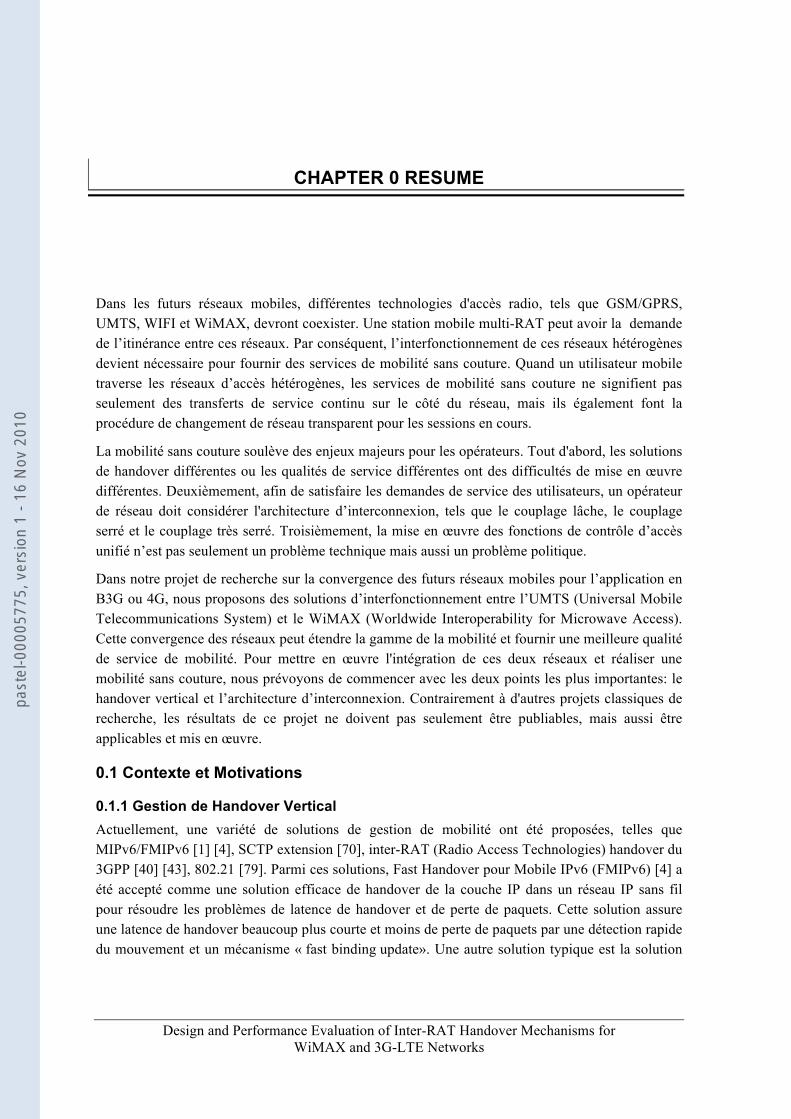
Dans les futurs réseaux mobiles, différentes technologies d'accès radio, tels que GSM/GPRS, UMTS, WIFI et WiMAX, devront coexister. Une station mobile multi-RAT peut avoir la demande de l’itinérance entre ces réseaux. Par conséquent, l’interfonctionnement de ces réseaux hétérogènes devient nécessaire pour fournir des services de mobilité sans couture. Quand un utilisateur mobile traverse les réseaux d’accès hétérogènes, les services de mobilité sans couture ne signifient pas seulement des transferts de service continu sur le côté du réseau, mais ils également font la procédure de changement de réseau transparent pour les sessions en cours.
La mobilité sans couture soulève des enjeux majeurs pour les opérateurs. Tout d'abord, les solutions de handover différentes ou les qualités de service différentes ont des difficultés de mise en œuvre différentes. Deuxièmement, afin de satisfaire les demandes de service des utilisateurs, un opérateur de réseau doit considérer l'architecture d’interconnexion, tels que le couplage lâche, le couplage serré et le couplage très serré. Troisièmement, la mise en œuvre des fonctions de contrôle d’accès unifié n’est pas seulement un problème technique mais aussi un problème politique.
Dans notre projet de recherche sur la convergence des futurs réseaux mobiles pour l’application en B3G ou 4G, nous proposons des solutions d’interfonctionnement entre l’UMTS (Universal Mobile Telecommunications System) et le WiMAX (Worldwide Interoperability for Microwave Access). Cette convergence des réseaux peut étendre la gamme de la mobilité et fournir une meilleure qualité de service de mobilité. Pour mettre en œuvre l'intégration de ces deux réseaux et réaliser une mobilité sans couture, nous prévoyons de commencer avec les deux points les plus importantes: le handover vertical et l’architecture d’interconnexion. Contrairement à d'autres projets classiques de recherche, les résultats de ce projet ne doivent pas seulement être publiables, mais aussi être applicables et mis en œuvre.
0.1 Contexte et Motivations
0.1.1 Gestion de Handover Vertical Actuellement, une variété de solutions de gestion de mobilité ont été proposées, telles que MIPv6/FMIPv6 [1] [4], SCTP extension [70], inter-RAT (Radio Access Technologies) handover du 3GPP [40] [43], 802.21 [79]. Parmi ces solutions, Fast Handover pour Mobile IPv6 (FMIPv6) [4] a été accepté comme une solution efficace de handover de la couche IP dans un réseau IP sans fil pour résoudre les problèmes de latence de handover et de perte de paquets. Cette solution assure une latence de handover beaucoup plus courte et moins de perte de paquets par une détection rapide du mouvement et un mécanisme « fast binding update». Une autre solution typique est la solution
past
el-0
0005
775,
ver
sion
1 -
16 N
ov 2
010

Chapitre 0. Résumé
Design and Performance Evaluation of Inter-RAT Handover Mechanisms for WiMAX and 3G-LTE Networks
25
du 3GPP [40] [43]. Elle est également considérée comme un moyen prometteur en raison de sa grande fiabilité de handover, ce qui a permis qu’elle soit exploitée avec succès dans le marché depuis de nombreuses années. Malheureusement, les solutions 3GPP ne supportent que le handover entre les réseaux cellulaires, par exemple, entre le GSM et l’UMTS, mais ne supportent pas le handover entre réseaux IEEE 802 et réseaux cellulaires, par exemple, entre le WiMAX et l’UMTS. Outre Mobile IPv6 et ses extensions et les 3GPP solutions, la norme IEEE 802.21 [79] est un standard pour offrir un handover entre les réseaux hétérogènes. Il définit un ensemble de primitives et trois types de services: « Media Independent Event service », « Media Independent Command Service » et « Media Independent Information Service ». Comment réaliser un mécanisme de handover efficace pour résoudre les problèmes de handover est la tâche des opérateurs.
Dans cette thèse, nous ne considérons que le handover entre les réseaux hétérogènes. Nous utilisons les terminologies « handover vertical », « handover inter-RAT » et « handover » de façon interchangeable.
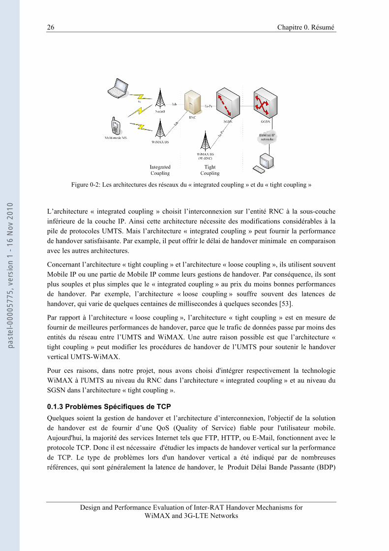
0.1.2 L’Architecture d’Interconnexion Un autre problème important pour la mobilité sans couture est l’architecture d’interconnexion et le scénario de couplage. Selon l'endroit où est le point de couplage, il existe plusieurs architectures d’interconnexion: pas de couplage (no coupling), couplage lâche (loose coupling), couplage serré (tight coupling) et couplage très serré (integrated coupling) [53].
Figure 0-1: L’Architecture des réseaux du « loose coupling »
Nous prenons l’interconnexion entre WiMAX et UMTS comme un exemple. Le « loose coupling » indique que le point de couplage est après le UMTS GGSN (Gateway GPRS Support Node), comme le montre dans la Fig. 0-1. Mais le point de couplage dans le « tight coupling » est au niveau du cœur de réseaux UMTS, tels que le SGSN (Serving GPRS Support Node) et le GGSN. Dans le « integrated coupling », le point de couplage est au niveau du réseau d’accès UMTS, tel que le RNC (Radio Network Controller), comme indiqué dans la Fig. 0-2.
past
el-0
0005
775,
ver
sion
1 -
16 N
ov 2
010
26 Chapitre 0. Résumé
Design and Performance Evaluation of Inter-RAT Handover Mechanisms for WiMAX and 3G-LTE Networks
Figure 0-2: Les architectures des réseaux du « integrated coupling » et du « tight coupling »
L’architecture « integrated coupling » choisit l’interconnexion sur l’entité RNC à la sous-couche inférieure de la couche IP. Ainsi cette architecture nécessite des modifications considérables à la pile de protocoles UMTS. Mais l’architecture « integrated coupling » peut fournir la performance de handover satisfaisante. Par example, il peut offrir le délai de handover minimale en comparaison avec les autres architectures.
Concernant l’architecture « tight coupling » et l’architecture « loose coupling », ils utilisent souvent Mobile IP ou une partie de Mobile IP comme leurs gestions de handover. Par conséquence, ils sont plus souples et plus simples que le « integrated coupling » au prix du moins bonnes performances de handover. Par exemple, l’architecture « loose coupling » souffre souvent des latences de handover, qui varie de quelques centaines de millisecondes à quelques secondes [53].
Par rapport à l’architecture « loose coupling », l’architecture « tight coupling » est en mesure de fournir de meilleures performances de handover, parce que le trafic de données passe par moins des entités du réseau entre l’UMTS and WiMAX. Une autre raison possible est que l’architecture « tight coupling » peut modifier les procédures de handover de l’UMTS pour soutenir le handover vertical UMTS-WiMAX.
Pour ces raisons, dans notre projet, nous avons choisi d'intégrer respectivement la technologie WiMAX à l'UMTS au niveau du RNC dans l’architecture « integrated coupling » et au niveau du SGSN dans l’architecture « tight coupling ».
0.1.3 Problèmes Spécifiques de TCP Quelques soient la gestion de handover et l’architecture d’interconnexion, l'objectif de la solution de handover est de fournir d’une QoS (Quality of Service) fiable pour l'utilisateur mobile. Aujourd'hui, la majorité des services Internet tels que FTP, HTTP, ou E-Mail, fonctionnent avec le protocole TCP. Donc il est nécessaire d'étudier les impacts de handover vertical sur la performance de TCP. Le type de problèmes lors d'un handover vertical a été indiqué par de nombreuses références, qui sont généralement la latence de handover, le Produit Délai Bande Passante (BDP)
past
el-0
0005
775,
ver
sion
1 -
16 N
ov 2
010
Chapitre 0. Résumé
Design and Performance Evaluation of Inter-RAT Handover Mechanisms for WiMAX and 3G-LTE Networks
27
« mismatch », le perte de paquets, le spike de délai, le timeout prématuré, et le « spurious RTO (Retransmission TimeOut) » [60]. En fait, tous ces problèmes ne peuvent pas être résolus par un seul schéma. Par exemple, les protocoles conventionnels de gestion de handover ont pour but de parvenir à une faible perte de paquets et/ou de réduire la latence de handover, à la couche IP (par exemple FMIPv6), à la couche liaison (par exemple, 3GPP handover inter-RAT), à la couche transport (par exemple, SCTP), même à la couche d’application (par exemple, SIP). Des solutions générales [60-66] sont proposées à la couche TCP, qui ne dépend pas d'une architecture d’interconnexion ou d’une procédure de handover de la couche inférieure. Toutefois, ces solutions demandent des modifications importantes sur la pile TCP [60] [61], ou souffrent de la perte de paquets au cours de handover [62], ou ont besoin de précis calcul du « warning period» [63], ou exigent une procédure de « soft » handover sur la couche IP [64].
0.2 Contributions Dans notre projet, sur l'interconnexion entre l’UMTS et le WiMAX, nous proposons une solution « cross-layer » de manière à résoudre les problèmes posés au niveau supérieur dans les architectures « tight coupling » et « integrated coupling ». Dans l’état actuel de nos connaissances, notre solution est la première solution complète destinée à plusieurs types de problèmes de handover inter-RAT. Pour faciliter les travaux de recherche, nous avons classé les problèmes de handover inter-RAT pour TCP en deux types: les pertes de paquets/longue latence de handover, et « BDP mismatch/ spurious RTO ». Pour le premier type de problèmes, nous proposons un nouveau protocole de gestion de handover à une nouvelle sous-couche commune à la couche 2. Pour le deuxième type de problèmes, nous proposons d'utiliser l’agent TCP Proxy pour fournir un mécanisme permettant de lisser les différences RTO et BDP des deux réseaux sans fil. Nos contributions peuvent être résumées comme suit:
• Nous utilisons une méthodologie de « timing diagramme » [26] pour analyser la performance de FMIPv6 sous l'hypothèse de couches inférieures parfaites, par exemple, pas de paquets stockées à la couche MAC/PHY au cours d'un handover, et on suppose l’existence de déclencheurs (triggers) « cross-layer » entre la couche IP et la couche liaison. Nous avons étudié le travail de Seung-Hee Hwang [26], en identifiant les conditions dans lesquelles la meilleure performance peut être atteinte et quelles sont les limites quand la FMIPv6 est utilisé comme le protocole de handover vertical.
• Sur la base de l'analyse de FMIPv6, nous proposons un nouveau système de handover inter-RAT à la couche 2 en introduisant une nouvelle sous-couche commune IW et le mécanisme SR-ARQ pour les problèmes de la perte de paquets et de latence de handover dans l’architectures « tight coupling » et « integrated coupling ».
• Par rapport au mécanisme de « buffering-and-forwarding » de FMIPv6, la simulation montre que le mécanisme IW ARQ a l’avantage de fournir une latence de handover plus courte et d’assurer l'absence de perte de paquets. La simulation montre également que les paquets perdus au niveau des couches basses au cours de le période de handover, qui sont souvent omis dans l’analyse de la performance FMIPv6 [4] [5], dégradent souvent les performances de FMIPv6. Nous avons également comparé la performance du mécanisme
past
el-0
0005
775,
ver
sion
1 -
16 N
ov 2
010

28 Chapitre 0. Résumé
Design and Performance Evaluation of Inter-RAT Handover Mechanisms for WiMAX and 3G-LTE Networks
IW ARQ à celle des autres mécanismes de transfert contexte: la reconstruction de SDU [57] et la R-LLC [56]. Les résultats de simulation montrent également leurs défauts et la supériorité du mécanisme IW ARQ.
• En outre, une solution basée sur TCP Proxy et un renforcement du TCP Proxy avec mécanisme « cross-layer » sont mis en place sur le RNC pour régler le deuxième type de problèmes de handover - « BDP mismatch /spurious RTO ». Le protocole TCP Proxy est conçu pour les scénarios de handover fréquent, tandis que l'amélioration de TCP Proxy est conçue pour les scénarios de handover occasionnel.
• De manière générale, toutes les solutions de handover classiques sont réalisés au niveau 2 ou plus, en raison de l'impossibilité d’un module commun à la couche physique ou de la distance géographique des deux systèmes. Mais pour les futurs systèmes LTE et WiMAX dans l’architecture « integrated coupling », cela n'est pas le cas, parce qu'ils ont un certain nombre de techniques physiques communes comme MIMO et OFDM. Deux modules communs nommés precodeur (precoder) et combineur (combiner) sont proposés respectivement dans les BSs et les MSs à la couche physique pour exploiter au maximum la diversité des deux systèmes. Ce « soft » handover inter-RAT à la couche physique est totalement nouveau.
Les contributions sont détaillées comme suit:
0.2.1 Handover Inter-RAT à la Couche Trois – Analyse de la Mode d’Opération FMIPv6
0.2.1.1 Vue d'Ensemble Afin de résoudre les problèmes, beaucoup de solutions ont été proposées. Par exemple, à la couche IP, en utilisant Mobile IP et ses extensions. Ce qui est un choix naturel parce que la couche IP est la couche commune future des réseaux sans fil. Ces types des solutions souffrent généralement d'une longue latence de handover et des potentielles pertes de paquets, même si elles sont faciles à mettre en œuvre dans les réseaux mobiles existants. Au cours des dernières années, la norme IEEE 802.21 [23] a été proposée et est considérée comme une solution prometteuse de handover vertical à la couche liaison. Toutefois, la norme 802.21 ne définit qu’un ensemble de signalisation, de messages et de services. Comment faire pour résoudre les problèmes de handover est toujours considéré comme le travail des opérateurs. Une autre solution prometteuse et perceptible à la couche liaison est la solution du 3GPP [43]. Mais cette solution ne considère pas handover entre les réseaux cellulaires et les réseaux IEEE 802. En outre, le 3GPP a sorti un standard d’interconnexion pour les systèmes UMTS et WIFI [88]. Malheureusement, cette norme se concentre seulement sur le plan contrôle et définit la topologie d’interconnexion, le AAA, et la passerelle d'accès. Elle ne résout pas les problèmes de handover dans le plan utilisateur. Dans la couche transport, des extensions de SCTP [70] et des solutions de type Freeze-TCP [63] sont proposées, mais elles ne sont pas applicables à certaines variantes de TCP.
past
el-0
0005
775,
ver
sion
1 -
16 N
ov 2
010
Chapitre 0. Résumé
Design and Performance Evaluation of Inter-RAT Handover Mechanisms for WiMAX and 3G-LTE Networks
29
Avant de présenter notre solution de handover inter-RAT, il est préférable d'étudier une solution de handover vertical typique au niveau 3 - Fast MIPv6 [4]. Les résultats de l'étude donnent quelques pistes pour la conception de mécanisme de handover.
Dans cette section, nous réalisons deux types d'étude: l’analyse numérique et l'émulation réseau. Pour l’analyse numérique, nous analysons les trois modes d’opération et l’évolution temporelle de FMIPv6. Ces trois modes d’opération sont en mode prédictif I, II et en mode réactif. Ici, nous supposons d'abord qu'il n’y a pas de perte de paquets dans les modes de prédiction, et seul le mode réactif souffre de la perte de paquets. Dans l’émulation de réseaux, nous mettons à côté cette hypothèse et étudions l'influence de la perte de paquets sur la latence de handover en mode prédictif.
0.2.1.2 L’Analyse Numérique
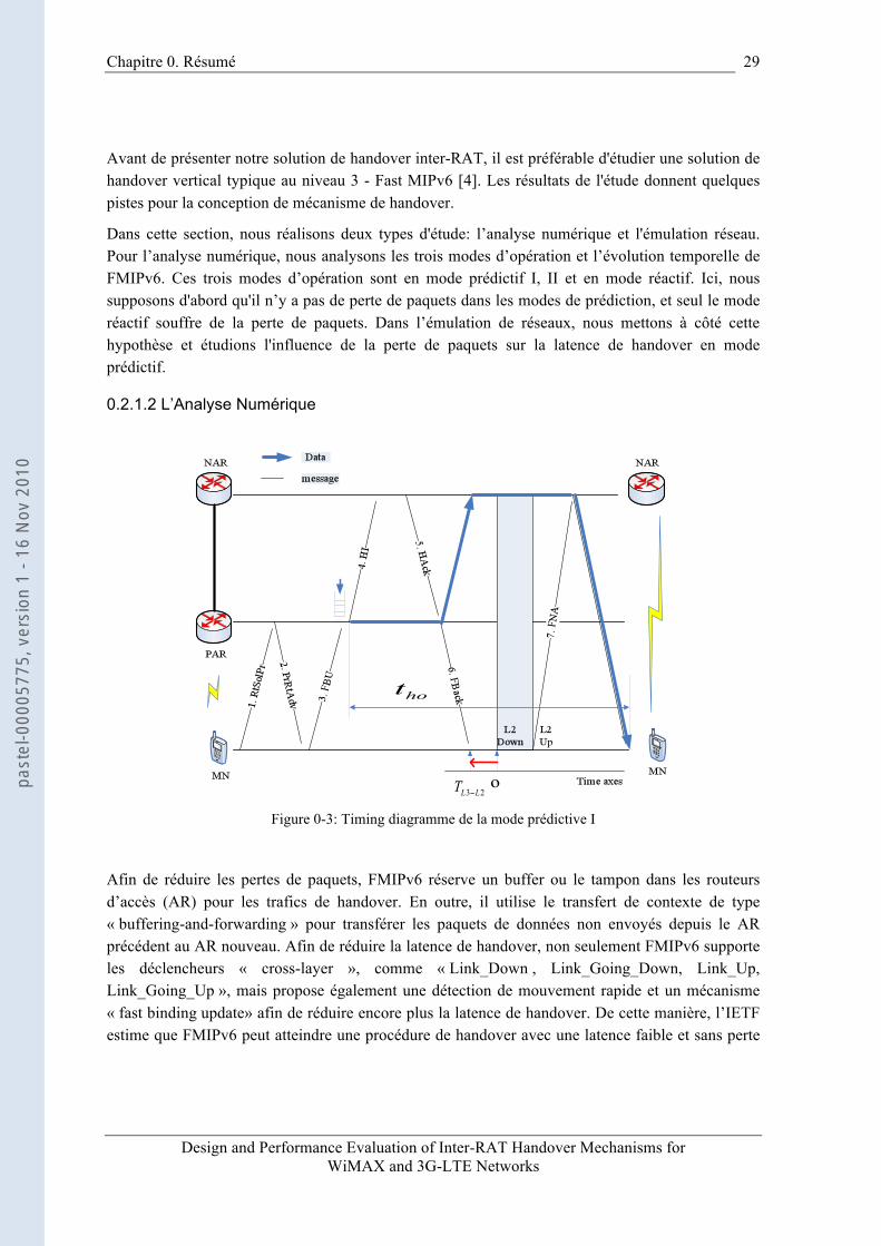
Figure 0-3: Timing diagramme de la mode prédictive I
Afin de réduire les pertes de paquets, FMIPv6 réserve un buffer ou le tampon dans les routeurs d’accès (AR) pour les trafics de handover. En outre, il utilise le transfert de contexte de type « buffering-and-forwarding » pour transférer les paquets de données non envoyés depuis le AR précédent au AR nouveau. Afin de réduire la latence de handover, non seulement FMIPv6 supporte les déclencheurs « cross-layer », comme « Link_Down , Link_Going_Down, Link_Up, Link_Going_Up », mais propose également une détection de mouvement rapide et un mécanisme « fast binding update» afin de réduire encore plus la latence de handover. De cette manière, l’IETF estime que FMIPv6 peut atteindre une procédure de handover avec une latence faible et sans perte
past
el-0
0005
775,
ver
sion
1 -
16 N
ov 2
010
30 Chapitre 0. Résumé
Design and Performance Evaluation of Inter-RAT Handover Mechanisms for WiMAX and 3G-LTE Networks
de paquet. Il est donc une solution prometteuse de handover vertical pour la convergence des futurs réseaux hétérogènes.
Dans la Fig. 0-3, Quand le nœud mobile (MN) se connecte avec le routeur d’accès précédent (PAR), it peut formuler une nouvelle CoA (NCoA) par l’échange des messages « Router Solicitation for Proxy (RtSolPr) » et « Proxy Router Advertisement (PrRtAdv) » avec PAR. Réagissant au déclencheur « Link_Going_Down », le MN envoie cette nouvelle CoA à PAR dans le message FBU. Sur la réception de ce message, le PAR, non seulement sauvegarde les paquets de données destinés au MN, mais envoie également cette nouvelle CoA au NAR pour validation. Lorsque le PAR reçoit l’accusé de réception de la part du NAR, il non seulement transfère les paquets sauvegardés à NAR, mais envoie également le message FBack au MN. Si le MN peut recevoir ce message FBack sur le lien précédent, nous appelons cette opération en mode prédictif I. Nous considérons le temps où le lien tombe comme le temps de référence, et on indique par l’instant où le message FBack est reçu sur le lien précédent. Ici, dans le but de simplifier l'analyse, nous supposons que le temps pourrait être négatif. Si est inférieur à zéro, le Fast MIPv6 fonctionne en mode prédictif I.
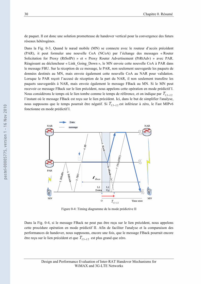
Figure 0-4: Timing diagramme de la mode prédictive II
Dans la Fig. 0-4, si le message FBack ne peut pas être reçu sur le lien précédent, nous appelons cette procédure opération en mode prédictif II. Afin de faciliter l'analyse et la comparaison des performances de handover, nous supposons, encore une fois, que le message FBack pourrait encore être reçu sur le lien précédent et que est plus grand que zéro.
past
el-0
0005
775,
ver
sion
1 -
16 N
ov 2
010
Chapitre 0. Résumé
Design and Performance Evaluation of Inter-RAT Handover Mechanisms for WiMAX and 3G-LTE Networks
31
Le troisième mode est le mode réactif, ce qui signifie que le MN se déplace trop rapidement pour envoyer un FBU sur le lien précédent. Ainsi, l'ensemble de la procédure d’opération est similaire à celui de Mobile IPv6.
0.2.1.3 Les Résultats Numériques pour du Trafics UDP
(a) (b)
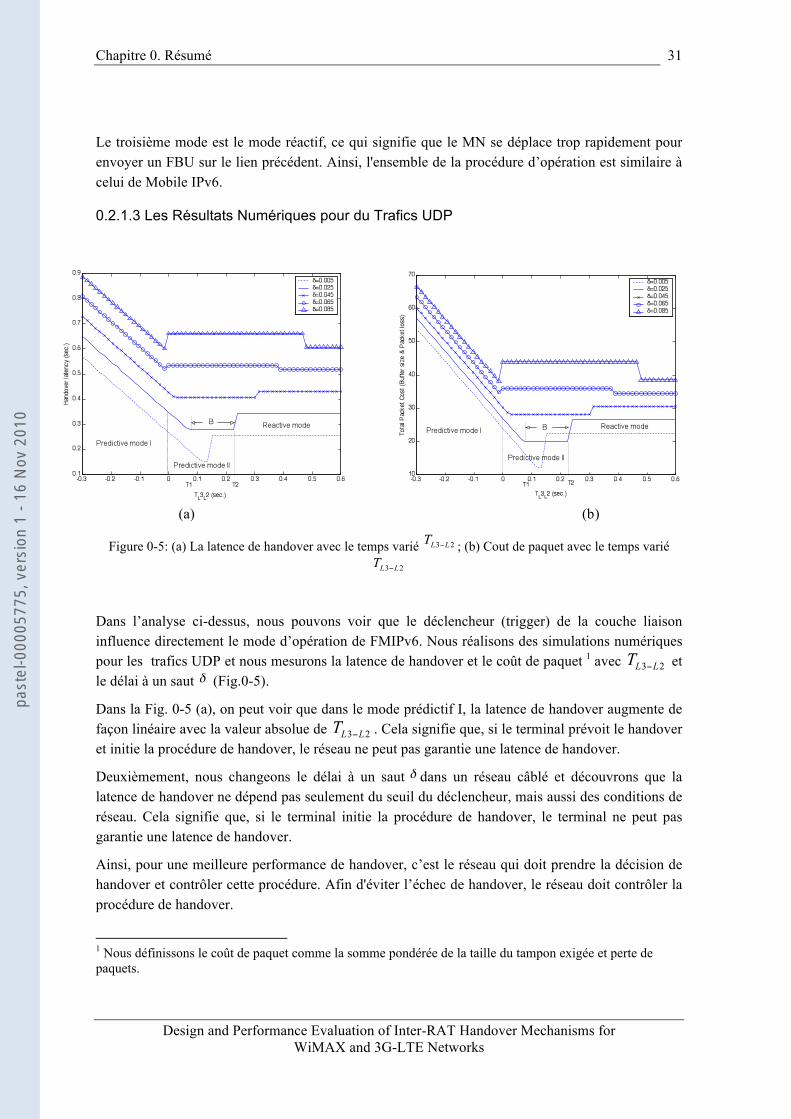
Figure 0-5: (a) La latence de handover avec le temps varié ; (b) Cout de paquet avec le temps varié
Dans l’analyse ci-dessus, nous pouvons voir que le déclencheur (trigger) de la couche liaison influence directement le mode d’opération de FMIPv6. Nous réalisons des simulations numériques pour les trafics UDP et nous mesurons la latence de handover et le coût de paquet 1 avec et le délai à un saut (Fig.0-5).
Dans la Fig. 0-5 (a), on peut voir que dans le mode prédictif I, la latence de handover augmente de façon linéaire avec la valeur absolue de . Cela signifie que, si le terminal prévoit le handover et initie la procédure de handover, le réseau ne peut pas garantie une latence de handover.
Deuxièmement, nous changeons le délai à un saut dans un réseau câblé et découvrons que la latence de handover ne dépend pas seulement du seuil du déclencheur, mais aussi des conditions de réseau. Cela signifie que, si le terminal initie la procédure de handover, le terminal ne peut pas garantie une latence de handover.
Ainsi, pour une meilleure performance de handover, c’est le réseau qui doit prendre la décision de handover et contrôler cette procédure. Afin d'éviter l’échec de handover, le réseau doit contrôler la procédure de handover.
1 Nous définissons le coût de paquet comme la somme pondérée de la taille du tampon exigée et perte de paquets.
past
el-0
0005
775,
ver
sion
1 -
16 N
ov 2
010
32 Chapitre 0. Résumé
Design and Performance Evaluation of Inter-RAT Handover Mechanisms for WiMAX and 3G-LTE Networks
Il faut noter que lorsque est dans la région B ([T1, T2]), la latence de handover est inchangeable, et est déterminée par l’instant où les paquets « tunnelled » arrivent. Lorsque le MN est en mode réactif, le handover n'a aucun rapport avec le temps . Sa latence et le coût correspondant aux paquets sont constant et déterminé, si le temps DAD est donné ou négligeable. Par conséquent, lorsque le délai à un saut est inférieur à un certain seuil, la région B est une région souhaitée pour le handover, qui peut remettre une latence minimale et assurer moins des pertes de paquets.
Basé sur les analyses, nous tirons les conclusions suivantes:
• Les délais de transmission entre PAR et NAR sont inférieurs à un certain seuil, afin de réaliser la meilleure performance de handover, le MN ne doit pas nécessairement recevoir le message FBU sur le lien précédent 2.
• Lorsque le MN fonctionne en mode prédictif, la performance de handover dépend fortement de la bonne conception du seuil du déclencheur. La mauvaise conception du seuil du déclencheur peut non seulement réduire la certitude sur la cible de handover, mais augmenter également la latence de handover.
• La latence de handover en mode réactif est toujours plus longue que la plus courte du mode prédictif. Cependant, la latence de handover est indépendante du temps de déclencheur à la couche liaison, et peut être prédite, étant donnés les paramètres du réseau tels que les délai de transmission et le temps DAD.
• Bien que FMIPv6 réalise une meilleure performance de handover que Mobile IPv6, la latence de handover de la couche liaison est toujours une limitation.
• Ce type de handover contrôlé par le terminal est appelé sélection/re-sélection de cellule dans les standards de 3GPP tel que l'UMTS. Dans le GERAN ou l’UMTS, la procédure de handover est contrôlée par le réseau. Ce type d'approche peut apporter des améliorations en termes de perte de paquets et de délai de handover.
Il faut souligner que les analyses temporelles du FMIPv6 sont basées sur l'hypothèse qu'il n'y a pas des pertes de paquets en mode prédictif. En fait, cette hypothèse est discutable. Dans la prochaine section, nous allons montrer que les pertes de paquets à la couche liaison dégradent considérablement les performances de handover FMIPv6, même en mode prédictif.
0.2.1.4 Les Résultats Numériques pour du Trafics TCP Dans les études sur le TCP, on ne considère que la latence de handover parce que le problème de la perte de paquets peut être résolu par le mécanisme de retransmission du TCP. Dans la Fig. 0-6 (a), la variation de la latence de handover d’une connexion TCP vs. l’instant du déclencheur du handover à la couche liaison est représenté. Cette figure est semblable à la Fig. 0-5 (a), sauf qu'elle montre une plus grande latence de handover en mode réactif.
2 Cette conclusion est similaire à la conclusion en [26].
past
el-0
0005
775,
ver
sion
1 -
16 N
ov 2
010
Chapitre 0. Résumé
Design and Performance Evaluation of Inter-RAT Handover Mechanisms for WiMAX and 3G-LTE Networks
33
(a) (b)
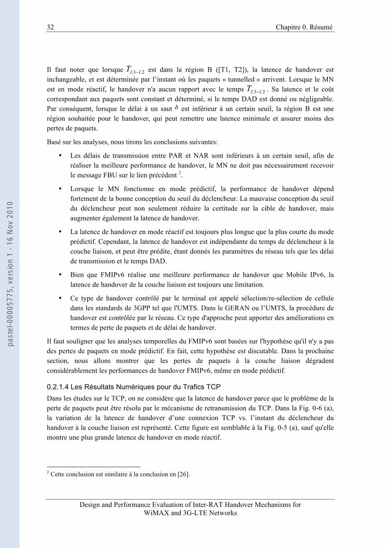
Figure 0-6: (a) La TCP latence de handover vs. le temps du déclencheur; (b) la TCP latence de handover vs. la latence de transmission par saut entre le PAR et le NAR en mode réactif
Afin d'expliquer les relations entre la latence de handover et le RTO, nous nous concentrons sur le comportement de handover en mode réactif, ce qui est montré dans la Fig. 0-6 (b). Dans la Fig. 0-6 (b), la latence de handover n'est pas linéaire quand le délai de transmission par saut entre le PAR et la NAR augmente. Dans le cas où RTO = 0,45 sec, lorsque la durée de la première retransmission est plus grande que la latence de handover de FMIPv6 en mode réactif, la latence de handover de TCP est déterminé par la première retransmission des paquets. Toutefois, lorsque le délai de transmission par saut augmente, il est probable que le premier paquet retransmis est envoyé à partir du PAR au NAR par l'intermédiaire d'un tunnel établi, et puis au MN. Ainsi, la latence de handover est une fonction linéaire du délai de transmission par saut. Lorsque le délai de transmission par saut dépasse une certaine limite, le premier paquet retransmis est perdu en raison de la perte de paquets en mode réactif. Sous cette condition, la latence de handover du TCP est déterminée par la deuxième retransmission. C'est la raison pour laquelle il existe respectivement deux valeurs constantes de la latence de handover au début du 1er RTO et au début du 2ème RTO dans la Fig. 0-6 (b).
De la simulation numérique du trafic TCP, nous pouvons conclure que:
• La latence de handover de la connexion TCP dans le FMIPv6 est très sensible à la perte de paquets en mode réactif.
Pour éviter les temps d'attente inutile de retransmission, il est prévu que le FMIPv6 fonctionne en mode prédictif. En outre, le PAR a besoin d'être sûr que les paquets sauvegardés sont tunnellés à la bonne NAR cible pour éviter la perte de paquets. Par conséquent, il est préférable que le réseau prend la décision de handover et que le MN doit respecter la décision du réseau et basculer vers le réseau désigné et ciblé, même quand le MN a scanné plus d'un AP.
past
el-0
0005
775,
ver
sion
1 -
16 N
ov 2
010
34 Chapitre 0. Résumé
Design and Performance Evaluation of Inter-RAT Handover Mechanisms for WiMAX and 3G-LTE Networks
0.2.1.5 La Emulation du Réseau
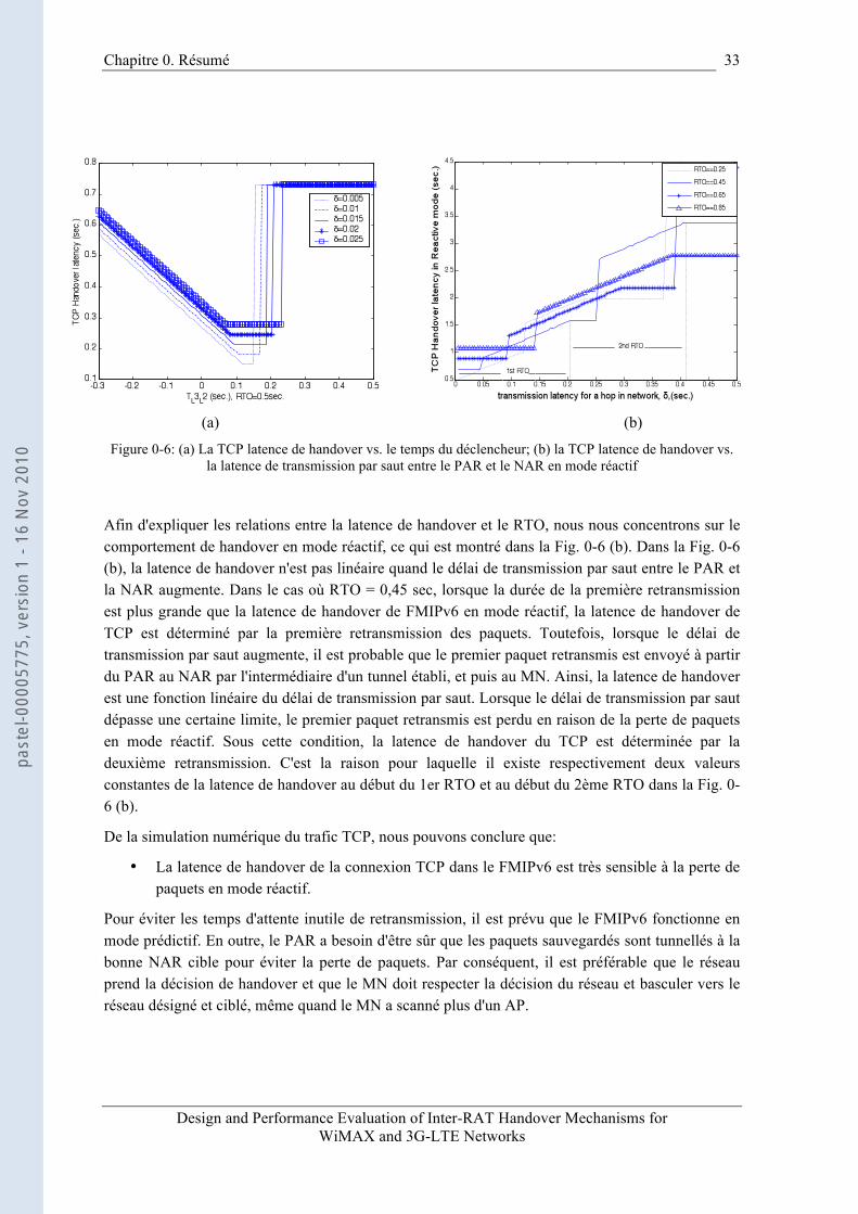
Figure 0-7: Topologie pour la simulation du réseau
Dans la section précédente, nous procédons aux analyses numériques sous l'hypothèse où il n'y a pas de perte de paquets à la couche liaison en mode prédictif au cours d'une période de handover. De manière générale, cette hypothèse est vraie dans le mode prédictif I, parce que le FBack est le dernier paquet transmis par le PAR au MN, si le MN peut le recevoir sur le lien sans fil PAR et les paquets arrivent au MN dans l’ordre. Après le FBack, les paquets suivants ne seront pas transmis sur le lien sans fil précédent. Toutefois, en mode prédictif II et en mode réactif, certains paquets qui sont transmis, à la couche liaison ou à la couche physique avant l'arrivée de FBack pourraient être perdus en raison de l'imprévisibilité du temps de handover du MN. La perte de paquets complique l'analyse numérique de la performance de handover pour le trafic TCP. Pour cette raison, nous réalisons une simulation de réseau pour identifier l’influence de la perte de paquets sur la latence de handover en mode prédictif II.
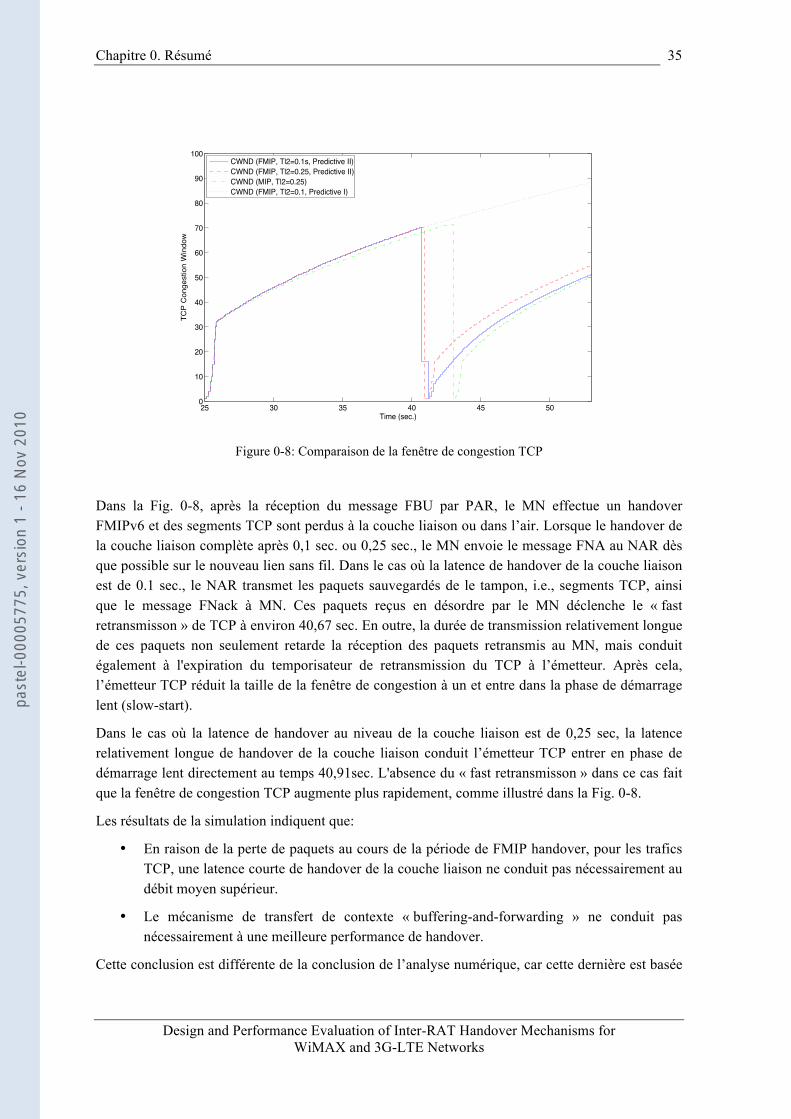
Dans la Fig. 0-7, les paquets de données FTP sont envoyés du CN au MN à l’instant 25sec. La technologie de la liaison sans fil est IEEE802.11 et le MN se déplace de la couverture PAR à la couverture NAR à une vitesse constante de 2 mètres par seconde. Nous effectuons un handover FMIPv6 en mode prédictif II dès que possible le PAR reçoit le message FBU du MN lorsque le délai de handover de la couche liaison est de 0,1 sec. ou 0,25 sec.
past
el-0
0005
775,
ver
sion
1 -
16 N
ov 2
010
Chapitre 0. Résumé
Design and Performance Evaluation of Inter-RAT Handover Mechanisms for WiMAX and 3G-LTE Networks
35
25 30 35 40 45 500
10
20
30
40
50
60
70
80
90
100
Time (sec.)
TCP
Con
gest
ion
Win
dow
CWND (FMIP, Tl2=0.1s, Predictive II)CWND (FMIP, Tl2=0.25, Predictive II)CWND (MIP, Tl2=0.25)CWND (FMIP, Tl2=0.1, Predictive I)
Figure 0-8: Comparaison de la fenêtre de congestion TCP
Dans la Fig. 0-8, après la réception du message FBU par PAR, le MN effectue un handover FMIPv6 et des segments TCP sont perdus à la couche liaison ou dans l’air. Lorsque le handover de la couche liaison complète après 0,1 sec. ou 0,25 sec., le MN envoie le message FNA au NAR dès que possible sur le nouveau lien sans fil. Dans le cas où la latence de handover de la couche liaison est de 0.1 sec., le NAR transmet les paquets sauvegardés de le tampon, i.e., segments TCP, ainsi que le message FNack à MN. Ces paquets reçus en désordre par le MN déclenche le « fast retransmisson » de TCP à environ 40,67 sec. En outre, la durée de transmission relativement longue de ces paquets non seulement retarde la réception des paquets retransmis au MN, mais conduit également à l'expiration du temporisateur de retransmission du TCP à l’émetteur. Après cela, l’émetteur TCP réduit la taille de la fenêtre de congestion à un et entre dans la phase de démarrage lent (slow-start).
Dans le cas où la latence de handover au niveau de la couche liaison est de 0,25 sec, la latence relativement longue de handover de la couche liaison conduit l’émetteur TCP entrer en phase de démarrage lent directement au temps 40,91sec. L'absence du « fast retransmisson » dans ce cas fait que la fenêtre de congestion TCP augmente plus rapidement, comme illustré dans la Fig. 0-8.
Les résultats de la simulation indiquent que:
• En raison de la perte de paquets au cours de la période de FMIP handover, pour les trafics TCP, une latence courte de handover de la couche liaison ne conduit pas nécessairement au débit moyen supérieur.
• Le mécanisme de transfert de contexte « buffering-and-forwarding » ne conduit pas nécessairement à une meilleure performance de handover.
Cette conclusion est différente de la conclusion de l’analyse numérique, car cette dernière est basée
past
el-0
0005
775,
ver
sion
1 -
16 N
ov 2
010
36 Chapitre 0. Résumé
Design and Performance Evaluation of Inter-RAT Handover Mechanisms for WiMAX and 3G-LTE Networks
sur l’hypothèse qu’il n’y a pas de perte de paquets en mode prédictif.
D’un autre côté, le « buffering-and-forwarding » est toujours un système de transfert de contexte bien acceptable pour la couche IP, car il n’y a aucune modification des piles du protocole IP au niveau du MN. La modification des piles du protocole IP au MN n'est pas acceptable pour les réseaux IP sans fil et filaires. Pour ces raisons, la solution de handover sans couture, devrait déployer un système efficace de contexte de transfert au lieu du « buffering-and-forwarding » à d'autres couches, plutôt que de la couche IP, par exemple, la couche liaison.
0.2.1.6 Conclusion Le FMIPv6 réduit la latence de handover et la perte de paquets de MIPv6 par les mécanismes de la détection rapide du mouvement et le « fast binding update». Mais il souffre de la latence de handover incertain causé par les déclencheurs de la couche liaison, en particulier pour le trafic temps réel comme la VoIP. Nous avons d'abord procédé à l'analyse numérique et l'émulation du réseau pour étudier la performance de handover FMIPv6, et obtenu des pistes pour la conception du mécanisme de handover.
0.2.2 Handover Inter-RAT à la Couche Deux – la Solution Sous-couche IW
0.2.2.1 Vue d’ensemble Dans la section précédente, nous mettons en évidence les inconvénients de la gestion de mobilité FMIPv6 pour les futurs réseaux mobiles (B3G ou 4G). Nos conclusions principales de la section précédente sont:
• Le handover vertical doit être effectué à un niveau inférieur à la couche 3 pour un délai de handover plus court.
• C’est le réseau qui doit prendre la décision de handover et contrôler la procédure de handover vertical (par exemple, décider quand le handover est effectué et où est le réseau cible de handover).
• Le réseau doit avoir un mécanisme efficace de transfert de contexte pour éviter les pertes de paquets pendant la période de handover.
Dans cette section, nous passons au handover vertical de la couche liaison. Au 3GPP, le handover vertical est nommé handover inter-RAT. Afin de se différentier de handover conventionnel de Mobile IP, nous préférons utiliser la terminologie inter-RAT (Radio Access Technology) handover dans les sections suivantes.
Généralement, l'interconnexion de l’UMTS et du WiMAX relève de nombreux défis. Tout d'abord, dans l'architecture « integrated coupling » et l'architecture « tight coupling », on ne peut pas appliquer directement les solutions du Mobile IP. Un mécanisme de handover de la couche liaison est nécessaire.
Deuxièmement, la sous-couche PDCP de l'UMTS et la sous-couche MAC du WiMAX ont des mécanismes différents de compression d'en-tête. Si les paquets ou les segments stockés de la couche liaison source avec leurs en-têtes particuliers sont directement transmis à la couche liaison
past
el-0
0005
775,
ver
sion
1 -
16 N
ov 2
010

Chapitre 0. Résumé
Design and Performance Evaluation of Inter-RAT Handover Mechanisms for WiMAX and 3G-LTE Networks
37
cible, ce dernier peut jeter ces paquets illisibles.
Le troisième défi est que le système WiMAX n'a pas de mécanisme de synchronisation du numéro de séquence pour la procédure de re-sélection.
Quatrièmement, le WiMAX supporte la re-sélection de cellules initiée par le terminal pour des trafics actifs, ce qui n’est pas le cas de l'UMTS. Cela signifie que les paquets qui sont perdus au cours de la re-sélection de cellule à partir du WiMAX à l'UMTS, ne peuvent être retransmis par le réseau UMTS cible. A cet effet, il ne doit exister un mécanisme commun de synchronisation du nombre de séquence des paquets pour les deux systèmes.
Le cinquième défi est l'actuel standard 3GPP sur l’interconnexion [88] pour l'UMTS et le WIFI qui n'indique pas comment résoudre les problèmes de handover dans le plan utilisateur.
Par conséquent, un handover inter-RAT efficace doit avoir une unité de traitement et de traduction de signalisation commune aux deux systèmes. En outre, il doit disposer d'un système efficace de transfert de contexte au lieu du « buffering-and-forwarding ».
Pour ces raisons, dans cette section, une nouvelle sous-couche de protocole commun est conçue pour les deux systèmes. Dans cette sous-couche commune, un ensemble de primitives « cross-layer » et de messages sont également conçus. En outre, dans cette sous-couche commune, le mécanisme classique de « selective repeat ARQ » est présenté comme un système de transfert de contexte.
0.2.2.2 La Sous-couche IW dans l'Architecture « Integrated Coupling »
0.2.2.2.1 Description de la Sous-couche IW
Figure 0-9: Fonctionnement de la sous-couche IW du « integrated coupling »
past
el-0
0005
775,
ver
sion
1 -
16 N
ov 2
010
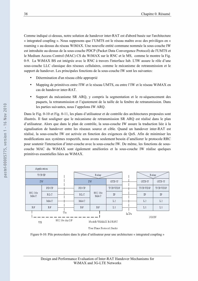
38 Chapitre 0. Résumé
Design and Performance Evaluation of Inter-RAT Handover Mechanisms for WiMAX and 3G-LTE Networks
Comme indiqué ci-dessus, notre solution de handover inter-RAT est d'abord basée sur l'architecture « integrated coupling ». Nous supposons que l’UMTS est le réseau maître avec des privilèges en « roaming » au-dessus du réseau WiMAX. Une nouvelle entité commune nommée la sous-couche IW est introduite au-dessus de la sous-couche PDCP (Packet Data Convergence Protocol) de l'UMTS et le Medium Access Control (MAC) CS du WiMAX sur le RNC et le MS, comme le montre la Fig. 0-9. La WiMAX BS est intégrée avec le RNC à travers l'interface Iub. L'IW assure le rôle d’une sous-couche LLC classique des réseaux cellulaires, comme le mécanisme de retransmission et le support de handover. Les principales fonctions de la sous-couche IW sont les suivantes:
• Détermination d'un réseau cible approprié
• Mapping de primitives entre l'IW et le réseau UMTS, ou entre l’IW et le réseau WiMAX en cas de handover inter-RAT.
• Support du mécanisme SR ARQ, y compris la segmentation et le re-séquencement des paquets, la retransmission et l’ajustement de la taille de la fenêtre de retransmission. Dans les parties suivantes, nous l’appelons IW ARQ.
Dans le Fig. 0-10 et Fig. 0-11, les plans d’utilisateur et de contrôle des architectures proposées sont illustrés. Il faut souligner que le mécanisme de retransmission SR ARQ est réalisé dans le plan d’utilisateur. Alors que dans le plan de contrôle, la sous-couche IW assure la traduction liée à la signalisation de handover entre les réseaux source et cible. Quand un handover inter-RAT est réalisé, la sous-couche IW est activée en fonction des exigences de QoS. Afin de minimiser les modifications aux systèmes respectifs, nous avons seulement besoin d’améliorer le protocole RRC pour soutenir l'interaction d’inter-couche avec la sous-couche IW. De même, les fonctions de sous-couche MAC du WiMAX sont également améliorées et la sous-couche IW réalise quelques primitives essentielles liées au WiMAX.
Figure 0-10: Pile protocolaire dans le plan d’utilisateur pour une architecture « integrated coupling »
past
el-0
0005
775,
ver
sion
1 -
16 N
ov 2
010

Chapitre 0. Résumé
Design and Performance Evaluation of Inter-RAT Handover Mechanisms for WiMAX and 3G-LTE Networks
39
Figure 0-11: Pile protocolaire dans le plan de contrôle pour une architecture « integrated coupling »
0.2.2.2.2 Transfert de Contexte et le Mécanisme IW ARQ Pour résoudre le problème de la perte de paquets pendant la procédure de handover, la solution la plus classique est l'application d’un mécanisme de transfert de contexte, comme le « buffering-and-forwarding », le reconstruction de SDU, le R-LLC. Dans FMIPv6, le « Buffering-and-forwarding » signifie que le PAR transmet les paquets de données non envoyés et également les paramètres de connexion au NAR pour éviter les pertes de paquets.
Dans le mécanisme reconstruction de SDU, après le handover, les segments stockés dans le tampon PDU du lien source sont d'abord reconstruits vers un SDU correspondant et puis transmis au lien cible avec les SDUs dans tampon SDU 3. Evidemment, la reconstruction de SDU souffre de la perte de paquets.
Dans le mécanisme R-LLC, la BS retransmet les paquets perdus quand un temporisateur de retransmission local expire. Toutefois, la durée du temporisateur de retransmission local est normalement fixée à 5sec, ce qui est évidemment non acceptable pour les trafics TCP.
Notre mécanisme IW ARQ est en fait un mécanisme de répétition sélective renforcée (ARQ). Il a deux nouvelles fonctionnalités. Premièrement, après le handover, la sous-couche IW peut adapter la taille de la fenêtre de retransmission à la taille cible du BPD. Deuxièmement, la sous-couche IW supporte le déclencheur « Link_Up » pour accélérer la procédure de handover.
Dans la Fig.0-12, deux sous-couches IW résident respectivement sur le RNC et le MS. Quand un handover est fait, les paquets à partir du numéro 4 au numéro 12 sont perdus au niveau des couches inférieures. En outre, l'ACK du paquet numéro 3 est également perdu. Après que le handover soit terminé, la sous-couche IW sur le RNC recevra un déclencheur « Link_Up » de la couche inférieure. Sur ce déclenchement, la sous-couche IW sur le RNC retransmet les données par paquets non envoyés à partir du numéro 3 immédiatement. En même temps, la sous-couche IW définit la taille 3 En général, dans la couche liaison, le tampon SDU stocke les paquets des couches supérieures. Le tampon PDU stocke les paquets vers les couches inférieures.
past
el-0
0005
775,
ver
sion
1 -
16 N
ov 2
010
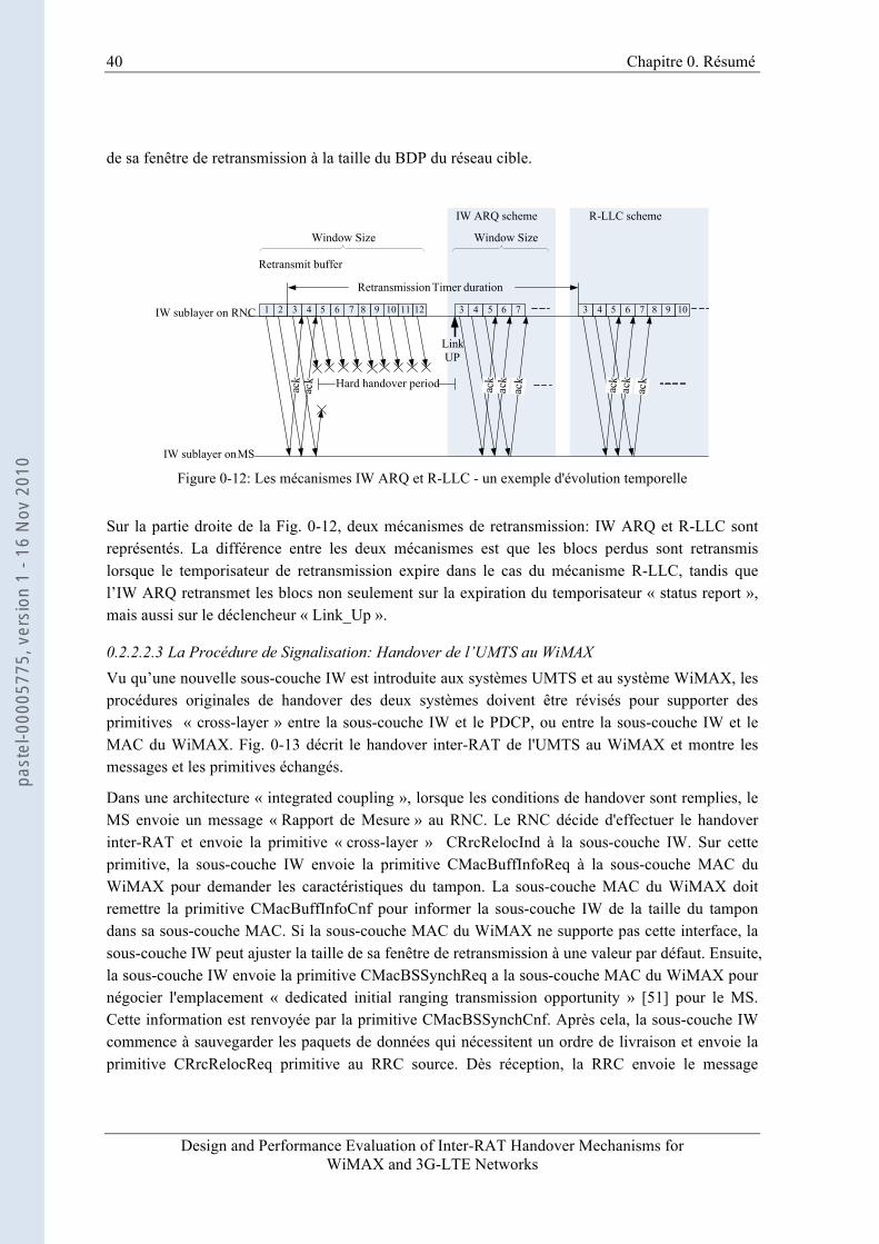
40 Chapitre 0. Résumé
Design and Performance Evaluation of Inter-RAT Handover Mechanisms for WiMAX and 3G-LTE Networks
de sa fenêtre de retransmission à la taille du BDP du réseau cible.
1 2 3 121110987654ac
kac
k Hard handover period
43
ack
5 6 7
LinkUP
Retransmit buffer
Window Size
ack
ack
Retransmission Timer duration
43
ack
5 6 7
ack
ack
Window Size
IW ARQ scheme R-LLC scheme
IW sublayer on RNC
IW sublayer on MS
8 9 10
Figure 0-12: Les mécanismes IW ARQ et R-LLC - un exemple d'évolution temporelle
Sur la partie droite de la Fig. 0-12, deux mécanismes de retransmission: IW ARQ et R-LLC sont représentés. La différence entre les deux mécanismes est que les blocs perdus sont retransmis lorsque le temporisateur de retransmission expire dans le cas du mécanisme R-LLC, tandis que l’IW ARQ retransmet les blocs non seulement sur la expiration du temporisateur « status report », mais aussi sur le déclencheur « Link_Up ».
0.2.2.2.3 La Procédure de Signalisation: Handover de l’UMTS au WiMAX Vu qu’une nouvelle sous-couche IW est introduite aux systèmes UMTS et au système WiMAX, les procédures originales de handover des deux systèmes doivent être révisés pour supporter des primitives « cross-layer » entre la sous-couche IW et le PDCP, ou entre la sous-couche IW et le MAC du WiMAX. Fig. 0-13 décrit le handover inter-RAT de l'UMTS au WiMAX et montre les messages et les primitives échangés.
Dans une architecture « integrated coupling », lorsque les conditions de handover sont remplies, le MS envoie un message « Rapport de Mesure » au RNC. Le RNC décide d'effectuer le handover inter-RAT et envoie la primitive « cross-layer » CRrcRelocInd à la sous-couche IW. Sur cette primitive, la sous-couche IW envoie la primitive CMacBuffInfoReq à la sous-couche MAC du WiMAX pour demander les caractéristiques du tampon. La sous-couche MAC du WiMAX doit remettre la primitive CMacBuffInfoCnf pour informer la sous-couche IW de la taille du tampon dans sa sous-couche MAC. Si la sous-couche MAC du WiMAX ne supporte pas cette interface, la sous-couche IW peut ajuster la taille de sa fenêtre de retransmission à une valeur par défaut. Ensuite, la sous-couche IW envoie la primitive CMacBSSynchReq a la sous-couche MAC du WiMAX pour négocier l'emplacement « dedicated initial ranging transmission opportunity » [51] pour le MS. Cette information est renvoyée par la primitive CMacBSSynchCnf. Après cela, la sous-couche IW commence à sauvegarder les paquets de données qui nécessitent un ordre de livraison et envoie la primitive CRrcRelocReq primitive au RRC source. Dès réception, la RRC envoie le message
past
el-0
0005
775,
ver
sion
1 -
16 N
ov 2
010
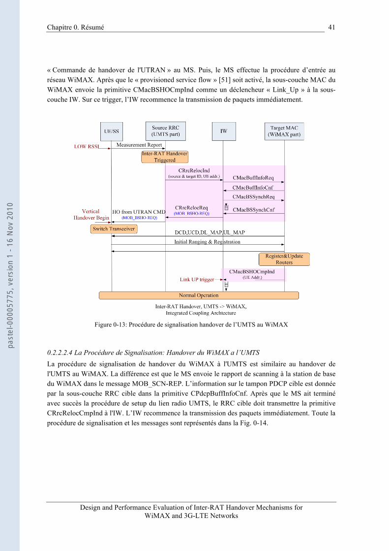
Chapitre 0. Résumé
Design and Performance Evaluation of Inter-RAT Handover Mechanisms for WiMAX and 3G-LTE Networks
41
« Commande de handover de l'UTRAN » au MS. Puis, le MS effectue la procédure d’entrée au réseau WiMAX. Après que le « provisioned service flow » [51] soit activé, la sous-couche MAC du WiMAX envoie la primitive CMacBSHOCmpInd comme un déclencheur « Link_Up » à la sous-couche IW. Sur ce trigger, l’IW recommence la transmission de paquets immédiatement.
Figure 0-13: Procédure de signalisation handover de l’UMTS au WiMAX
0.2.2.2.4 La Procédure de Signalisation: Handover du WiMAX a l’UMTS La procédure de signalisation de handover du WiMAX à l'UMTS est similaire au handover de l'UMTS au WiMAX. La différence est que le MS envoie le rapport de scanning à la station de base du WiMAX dans le message MOB_SCN-REP. L’information sur le tampon PDCP cible est donnée par la sous-couche RRC cible dans la primitive CPdcpBuffInfoCnf. Après que le MS ait terminé avec succès la procédure de setup du lien radio UMTS, le RRC cible doit transmettre la primitive CRrcRelocCmpInd à l'IW. L’IW recommence la transmission des paquets immédiatement. Toute la procédure de signalisation et les messages sont représentés dans la Fig. 0-14.
past
el-0
0005
775,
ver
sion
1 -
16 N
ov 2
010

42 Chapitre 0. Résumé
Design and Performance Evaluation of Inter-RAT Handover Mechanisms for WiMAX and 3G-LTE Networks
Figure 0-14: Procédure de signalisation de handover du WiMAX à l’UMTS
0.2.2.3 La Sous-couche IW dans l’Architecture « Tight Coupling »
0.2.2.3.1 Description de la Sous-couche IW Dans le scénario « tight coupling », le réseau WiMAX peut émuler un RNC ou un SGSN. Nous étudierons seulement l’émulation de RNC dans notre projet. Ainsi, on introduit un nouvel élément du réseau appelé émulateur RNC pour le WiMAX (W-RNC) dans le réseau d'accès WiMAX, qui se connecte au UMTS CN à l'interface Iu-PS, comme indiqué dans la Fig. 0-15. En fait, le W-RNC est une station de base WiMAX renforcée avec la sous-couche IW, qui se trouve au-dessus de la sous-couche MAC du WiMAX. Le W-RNC avec la sous-couche IW a les fonctions suivantes:
• Réalisation de l'interface Iu-PS.
• Mapping des primitives entre l’IW et le réseau UTRAN, ou entre l'IW et le réseau WiMAX.
• Pour la mobilité sans couture, la sous-couche IW a le mécanisme de retransmission inter-système – SR ARQ. Le mécanisme SR ARQ comprend la segmentation des paquets, le re-séquençage, la retransmission, et le réglage de la taille de la fenêtre de retransmission.
• Si un handover du WiMAX à l’UMTS a lieu, la sous-couche IW source transfère le contexte à la RNC cible. Sur le RNC, la sous-couche IW est réalisée au-dessus de la sous-couche PDCP. Sur le MS, la sous-couche IW est une sous-couche commune au-dessus de
past
el-0
0005
775,
ver
sion
1 -
16 N
ov 2
010
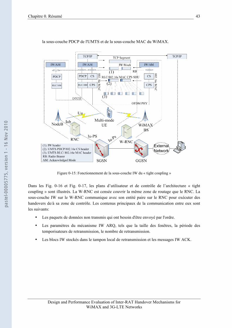
Chapitre 0. Résumé
Design and Performance Evaluation of Inter-RAT Handover Mechanisms for WiMAX and 3G-LTE Networks
43
la sous-couche PDCP de l'UMTS et de la sous-couche MAC du WiMAX.
Figure 0-15: Fonctionnement de la sous-couche IW du « tight coupling »
Dans les Fig. 0-16 et Fig. 0-17, les plans d’utilisateur et de contrôle de l’architecture « tight coupling » sont illustrés. La W-RNC est censée couvrir la même zone de routage que le RNC. La sous-couche IW sur le W-RNC communique avec son entité paire sur le RNC pour exécuter des handovers de/à sa zone de contrôle. Les contenus principaux de la communication entre eux sont les suivants:
• Les paquets de données non transmis qui ont besoin d'être envoyé par l'ordre.
• Les paramètres du mécanisme IW ARQ, tels que la taille des fenêtres, la période des temporisateurs de retransmission, le nombre de retransmission.
• Les blocs IW stockés dans le tampon local de retransmission et les messages IW ACK.
past
el-0
0005
775,
ver
sion
1 -
16 N
ov 2
010

44 Chapitre 0. Résumé
Design and Performance Evaluation of Inter-RAT Handover Mechanisms for WiMAX and 3G-LTE Networks
Figure 0-16: Pile protocolaire dans le plan d’utilisateur pour l’architecture « tight coupling »
Figure 0-17: Pile protocolaire dans le plan de contrôle pour l’architecture « tight coupling »
past
el-0
0005
775,
ver
sion
1 -
16 N
ov 2
010
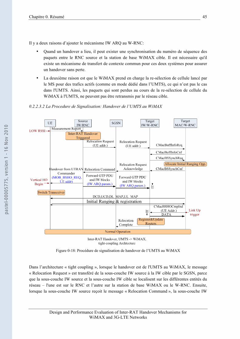
Chapitre 0. Résumé
Design and Performance Evaluation of Inter-RAT Handover Mechanisms for WiMAX and 3G-LTE Networks
45
Il y a deux raisons d’ajouter le mécanisme IW ARQ au W-RNC:
• Quand un handover a lieu, il peut exister une synchronisation du numéro de séquence des paquets entre le RNC source et la station de base WiMAX cible. Il est nécessaire qu'il existe un mécanisme de transfert de contexte commun pour ces deux systèmes pour assurer un handover sans perte.
• La deuxième raison est que le WiMAX prend en charge la re-sélection de cellule lancé par le MS pour des trafics actifs (comme en mode dédié dans l’UMTS), ce qui n’est pas le cas dans l'UMTS. Ainsi, les paquets qui sont perdus au cours de la re-sélection de cellule du WiMAX à l'UMTS, ne peuvent pas être retransmis par le réseau cible.
0.2.2.3.2 La Procedure de Signalisation: Handover de l’UMTS au WiMAX
Figure 0-18: Procédure de signalisation de handover de l’UMTS au WiMAX
Dans l’architecture « tight coupling », lorsque le handover est de l'UMTS au WiMAX, le message « Relocation Request » est transféré de la sous-couche IW source à la IW cible par le SGSN, parce que la sous-couche IW source et la sous-couche IW cible se localisent sur les différentes entités du réseau – l'une est sur le RNC et l’autre sur la station de base WiMAX ou le W-RNC. Ensuite, lorsque la sous-couche IW source reçoit le message « Relocation Command », la sous-couche IW
past
el-0
0005
775,
ver
sion
1 -
16 N
ov 2
010
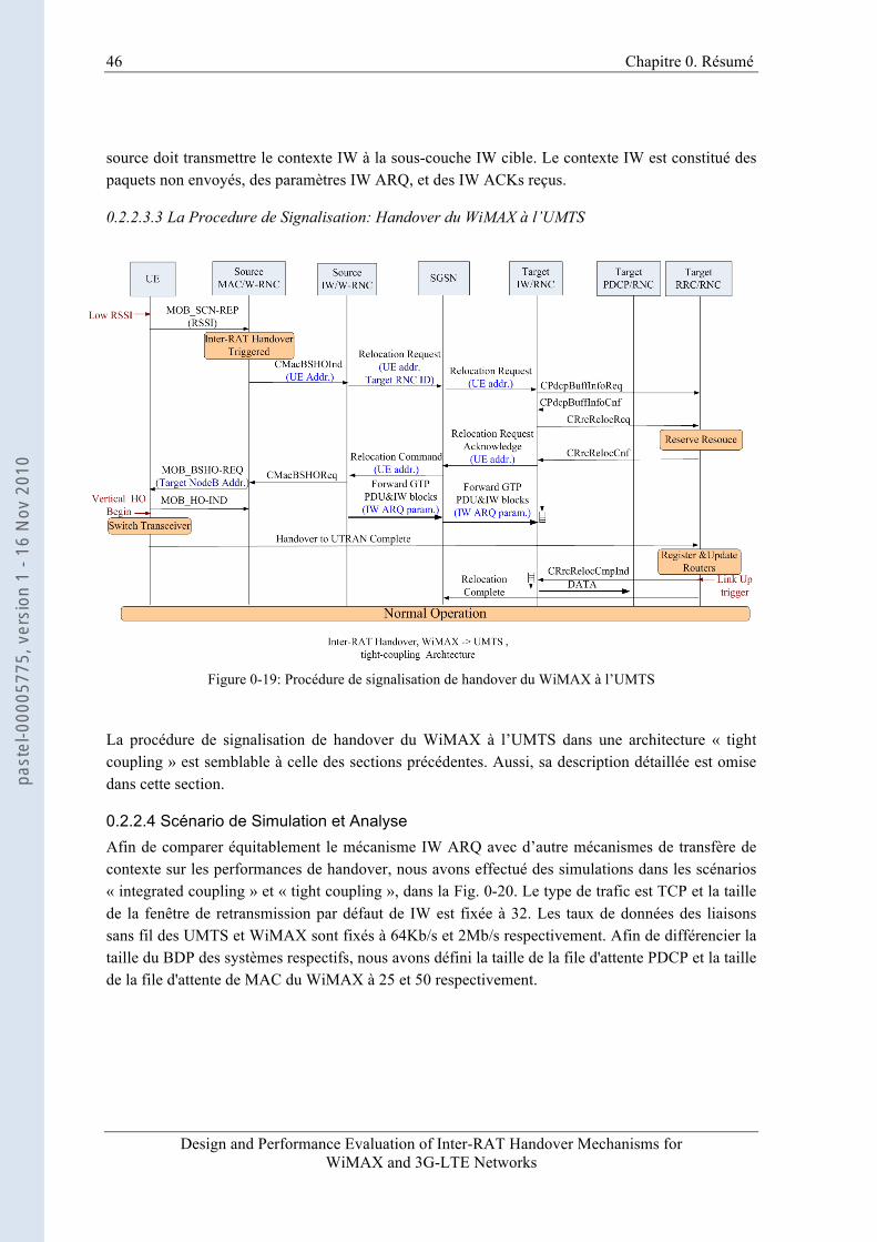
46 Chapitre 0. Résumé
Design and Performance Evaluation of Inter-RAT Handover Mechanisms for WiMAX and 3G-LTE Networks
source doit transmettre le contexte IW à la sous-couche IW cible. Le contexte IW est constitué des paquets non envoyés, des paramètres IW ARQ, et des IW ACKs reçus.
0.2.2.3.3 La Procedure de Signalisation: Handover du WiMAX à l’UMTS
Figure 0-19: Procédure de signalisation de handover du WiMAX à l’UMTS
La procédure de signalisation de handover du WiMAX à l’UMTS dans une architecture « tight coupling » est semblable à celle des sections précédentes. Aussi, sa description détaillée est omise dans cette section.
0.2.2.4 Scénario de Simulation et Analyse Afin de comparer équitablement le mécanisme IW ARQ avec d’autre mécanismes de transfère de contexte sur les performances de handover, nous avons effectué des simulations dans les scénarios « integrated coupling » et « tight coupling », dans la Fig. 0-20. Le type de trafic est TCP et la taille de la fenêtre de retransmission par défaut de IW est fixée à 32. Les taux de données des liaisons sans fil des UMTS et WiMAX sont fixés à 64Kb/s et 2Mb/s respectivement. Afin de différencier la taille du BDP des systèmes respectifs, nous avons défini la taille de la file d'attente PDCP et la taille de la file d'attente de MAC du WiMAX à 25 et 50 respectivement.
past
el-0
0005
775,
ver
sion
1 -
16 N
ov 2
010
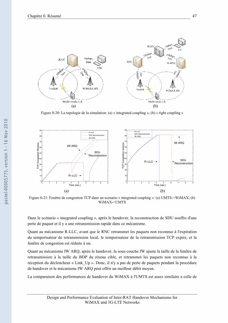
Chapitre 0. Résumé
Design and Performance Evaluation of Inter-RAT Handover Mechanisms for WiMAX and 3G-LTE Networks
47
(a) (b)
Figure 0-20: La topologie de la simulation: (a) « integrated coupling »; (b) « tight coupling »
0 1 2 3 4 5 6 7 8 90
10
20
30
40
50
60
70
80
90
Time (sec.)
TCP
Con
gest
ion
Win
dow
R LLCSDU ReconstructionIW ARQ
R LLC
SDU Reconstruction
IW ARQ
0 1 2 3 4 5 6 7 8 90
10
20
30
40
50
60
70
80
90
Time (sec.)
TCP
Con
gest
ion
win
dow
R LLCSDU ReconstructionIW ARQ
R LLC SDU Reconstruction
IW ARQ
(a) (b)
Figure 0-21: Fenêtre de congestion TCP dans un scenario « integrated coupling »: (a) UMTS->WiMAX; (b) WiMAX->UMTS
Dans le scénario « integrated coupling », après le handover, la reconstruction de SDU souffre d'une perte de paquet et il y a une retransmission rapide dans ce mécanisme.
Quant au mécanisme R-LLC, avant que le RNC retransmet les paquets non reconnus à l'expiration du temporisateur de retransmission local, le temporisateur de la retransmission TCP expire, et la fenêtre de congestion est réduite à un.
Quant au mécanisme IW ARQ, après le handover, la sous-couche IW ajuste la taille de la fenêtre de retransmission à la taille du BDP du réseau cible, et retransmet les paquets non reconnus à la réception du déclencheur « Link_Up ». Donc, il n'y a pas de perte de paquets pendant la procédure de handover et le mécanisme IW ARQ peut offrir un meilleur débit moyen.
La comparaison des performances de handover du WiMAX à l'UMTS est assez similaire a celle de
past
el-0
0005
775,
ver
sion
1 -
16 N
ov 2
010
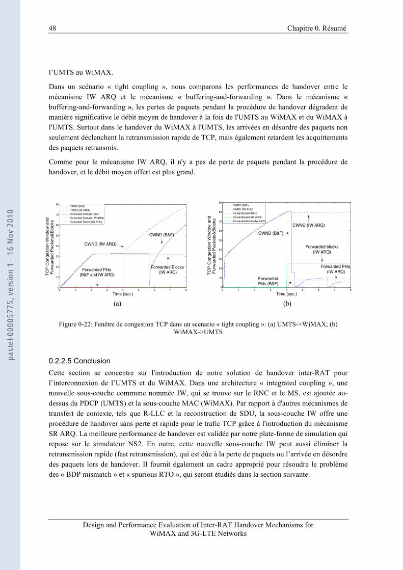
48 Chapitre 0. Résumé
Design and Performance Evaluation of Inter-RAT Handover Mechanisms for WiMAX and 3G-LTE Networks
l’UMTS au WiMAX.
Dans un scénario « tight coupling », nous comparons les performances de handover entre le mécanisme IW ARQ et le mécanisme « buffering-and-forwarding ». Dans le mécanisme « buffering-and-forwarding », les pertes de paquets pendant la procédure de handover dégradent de manière significative le débit moyen de handover à la fois de l'UMTS au WiMAX et du WiMAX à l'UMTS. Surtout dans le handover du WiMAX à l'UMTS, les arrivées en désordre des paquets non seulement déclenchent la retransmission rapide de TCP, mais également retardent les acquittements des paquets retransmis.
Comme pour le mécanisme IW ARQ, il n'y a pas de perte de paquets pendant la procédure de handover, et le débit moyen offert est plus grand.
0 1 2 3 4 5 6 7 80
10
20
30
40
50
60
70
80
Time (sec.)
TCP
Con
gest
ion
Win
dow
and
Fo
rwar
ded
Pac
kets
&B
lock
s
CWND (B&F)CWND (IW ARQ)Forwarded Packets (B&F)Forwarded Packets (IW ARQ)Forwarded Blocks (IW ARQ)
Forwarded Blocks (IW ARQ)Forwarded Pkts
(B&F and IW ARQ)
CWND (IW ARQ)
CWND (B&F)
0 1 2 3 4 5 6 7 80
10
20
30
40
50
60
70
80
90
Time (sec.)
TCP
Con
gest
ion
Win
dow
and
Fo
rwar
ded
Pac
kets
&B
lock
s
CWND (B&F)CWND (IW ARQ)Forwarded pkt (B&F)Forwarded pkt (IW ARQ)Forwarded blocks (IW ARQ)
CWND (IW ARQ)CWND (B&F)
Forwarded blocks(IW ARQ)
Forwarded Pkts (IW ARQ)
ForwardedPkts (B&F)
(a) (b)
Figure 0-22: Fenêtre de congestion TCP dans un scenario « tight coupling »: (a) UMTS->WiMAX; (b)
WiMAX->UMTS
0.2.2.5 Conclusion Cette section se concentre sur l'introduction de notre solution de handover inter-RAT pour l’interconnexion de l’UMTS et du WiMAX. Dans une architecture « integrated coupling », une nouvelle sous-couche commune nommée IW, qui se trouve sur le RNC et le MS, est ajoutée au-dessus du PDCP (UMTS) et la sous-couche MAC (WiMAX). Par rapport à d'autres mécanismes de transfert de contexte, tels que R-LLC et la reconstruction de SDU, la sous-couche IW offre une procédure de handover sans perte et rapide pour le trafic TCP grâce à l'introduction du mécanisme SR ARQ. La meilleure performance de handover est validée par notre plate-forme de simulation qui repose sur le simulateur NS2. En outre, cette nouvelle sous-couche IW peut aussi éliminer la retransmission rapide (fast retransmission), qui est dûe à la perte de paquets ou l’arrivée en désordre des paquets lors de handover. Il fournit également un cadre approprié pour résoudre le problème des « BDP mismatch » et « spurious RTO », qui seront étudiés dans la section suivante.
past
el-0
0005
775,
ver
sion
1 -
16 N
ov 2
010
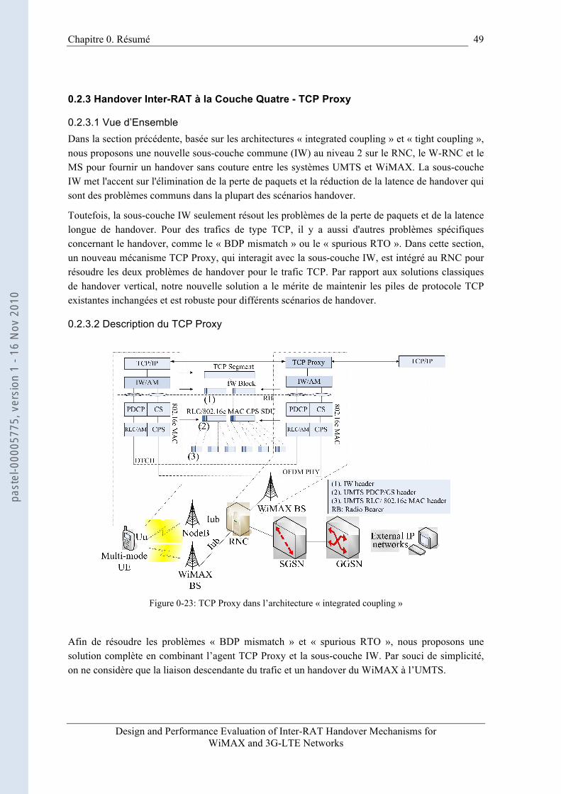
Chapitre 0. Résumé
Design and Performance Evaluation of Inter-RAT Handover Mechanisms for WiMAX and 3G-LTE Networks
49
0.2.3 Handover Inter-RAT à la Couche Quatre - TCP Proxy
0.2.3.1 Vue d’Ensemble Dans la section précédente, basée sur les architectures « integrated coupling » et « tight coupling », nous proposons une nouvelle sous-couche commune (IW) au niveau 2 sur le RNC, le W-RNC et le MS pour fournir un handover sans couture entre les systèmes UMTS et WiMAX. La sous-couche IW met l'accent sur l'élimination de la perte de paquets et la réduction de la latence de handover qui sont des problèmes communs dans la plupart des scénarios handover.
Toutefois, la sous-couche IW seulement résout les problèmes de la perte de paquets et de la latence longue de handover. Pour des trafics de type TCP, il y a aussi d'autres problèmes spécifiques concernant le handover, comme le « BDP mismatch » ou le « spurious RTO ». Dans cette section, un nouveau mécanisme TCP Proxy, qui interagit avec la sous-couche IW, est intégré au RNC pour résoudre les deux problèmes de handover pour le trafic TCP. Par rapport aux solutions classiques de handover vertical, notre nouvelle solution a le mérite de maintenir les piles de protocole TCP existantes inchangées et est robuste pour différents scénarios de handover.
0.2.3.2 Description du TCP Proxy
Figure 0-23: TCP Proxy dans l’architecture « integrated coupling »
Afin de résoudre les problèmes « BDP mismatch » et « spurious RTO », nous proposons une solution complète en combinant l’agent TCP Proxy et la sous-couche IW. Par souci de simplicité, on ne considère que la liaison descendante du trafic et un handover du WiMAX à l’UMTS.
past
el-0
0005
775,
ver
sion
1 -
16 N
ov 2
010
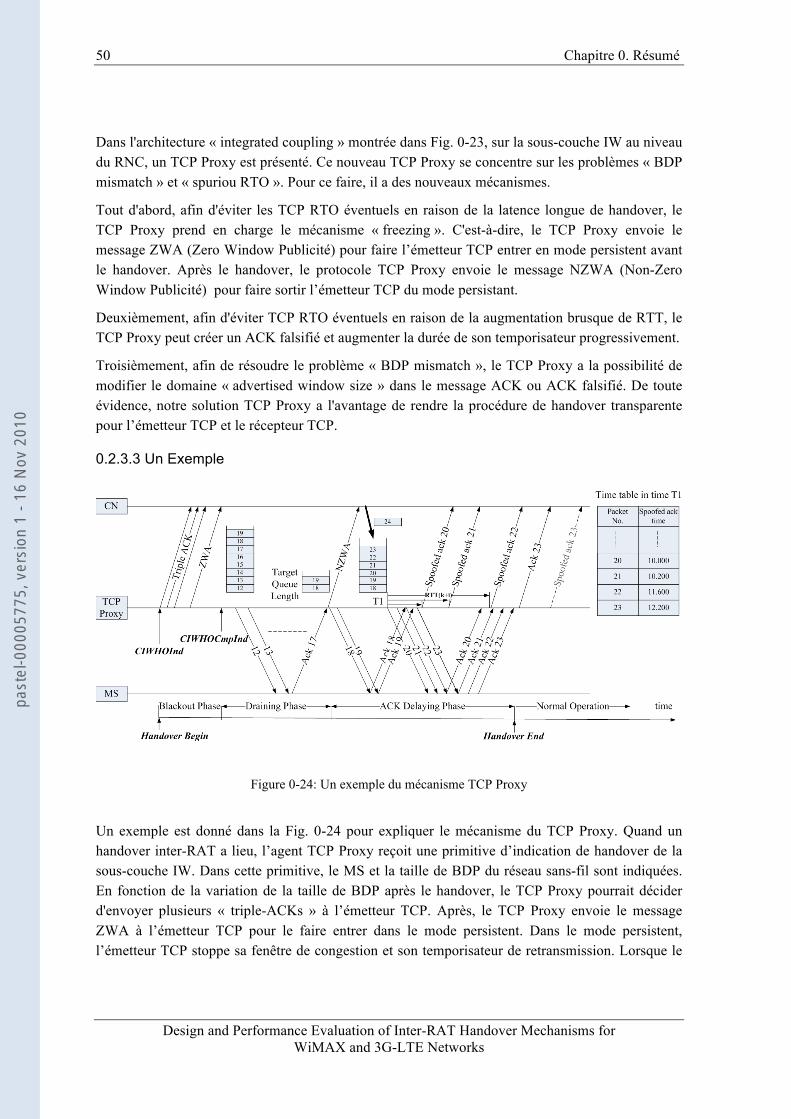
50 Chapitre 0. Résumé
Design and Performance Evaluation of Inter-RAT Handover Mechanisms for WiMAX and 3G-LTE Networks
Dans l'architecture « integrated coupling » montrée dans Fig. 0-23, sur la sous-couche IW au niveau du RNC, un TCP Proxy est présenté. Ce nouveau TCP Proxy se concentre sur les problèmes « BDP mismatch » et « spuriou RTO ». Pour ce faire, il a des nouveaux mécanismes.
Tout d'abord, afin d'éviter les TCP RTO éventuels en raison de la latence longue de handover, le TCP Proxy prend en charge le mécanisme « freezing ». C'est-à-dire, le TCP Proxy envoie le message ZWA (Zero Window Publicité) pour faire l’émetteur TCP entrer en mode persistent avant le handover. Après le handover, le protocole TCP Proxy envoie le message NZWA (Non-Zero Window Publicité) pour faire sortir l’émetteur TCP du mode persistant.
Deuxièmement, afin d'éviter TCP RTO éventuels en raison de la augmentation brusque de RTT, le TCP Proxy peut créer un ACK falsifié et augmenter la durée de son temporisateur progressivement.
Troisièmement, afin de résoudre le problème « BDP mismatch », le TCP Proxy a la possibilité de modifier le domaine « advertised window size » dans le message ACK ou ACK falsifié. De toute évidence, notre solution TCP Proxy a l'avantage de rendre la procédure de handover transparente pour l’émetteur TCP et le récepteur TCP.
0.2.3.3 Un Exemple
Figure 0-24: Un exemple du mécanisme TCP Proxy
Un exemple est donné dans la Fig. 0-24 pour expliquer le mécanisme du TCP Proxy. Quand un handover inter-RAT a lieu, l’agent TCP Proxy reçoit une primitive d’indication de handover de la sous-couche IW. Dans cette primitive, le MS et la taille de BDP du réseau sans-fil sont indiquées. En fonction de la variation de la taille de BDP après le handover, le TCP Proxy pourrait décider d'envoyer plusieurs « triple-ACKs » à l’émetteur TCP. Après, le TCP Proxy envoie le message ZWA à l’émetteur TCP pour le faire entrer dans le mode persistent. Dans le mode persistent, l’émetteur TCP stoppe sa fenêtre de congestion et son temporisateur de retransmission. Lorsque le
past
el-0
0005
775,
ver
sion
1 -
16 N
ov 2
010
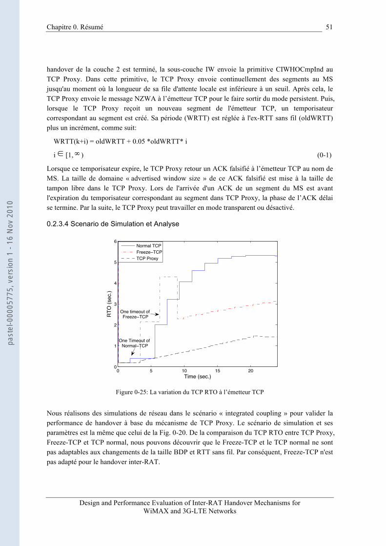
Chapitre 0. Résumé
Design and Performance Evaluation of Inter-RAT Handover Mechanisms for WiMAX and 3G-LTE Networks
51
handover de la couche 2 est terminé, la sous-couche IW envoie la primitive CIWHOCmpInd au TCP Proxy. Dans cette primitive, le TCP Proxy envoie continuellement des segments au MS jusqu'au moment où la longueur de sa file d'attente locale est inférieure à un seuil. Après cela, le TCP Proxy envoie le message NZWA à l’émetteur TCP pour le faire sortir du mode persistent. Puis, lorsque le TCP Proxy reçoit un nouveau segment de l'émetteur TCP, un temporisateur correspondant au segment est créé. Sa période (WRTT) est réglée à l'ex-RTT sans fil (oldWRTT) plus un incrément, comme suit:
WRTT(k+i) = oldWRTT + 0.05 *oldWRTT* i
i [1, ) (0-1)
Lorsque ce temporisateur expire, le TCP Proxy retour un ACK falsifié à l’émetteur TCP au nom de MS. La taille de domaine « advertised window size » de ce ACK falsifié est mise à la taille de tampon libre dans le TCP Proxy. Lors de l'arrivée d'un ACK de un segment du MS est avant l'expiration du temporisateur correspondant au segment dans TCP Proxy, la phase de l’ACK délai se termine. Par la suite, le TCP Proxy peut travailler en mode transparent ou désactivé.
0.2.3.4 Scenario de Simulation et Analyse
0 5 10 15 200
1
2
3
4
5
6
Time (sec.)
RTO
(sec
.)
Normal TCPFreeze TCPTCP Proxy
One timeout of Freeze TCP
One Timeout of Normal TCP
Figure 0-25: La variation du TCP RTO à l’émetteur TCP
Nous réalisons des simulations de réseau dans le scénario « integrated coupling » pour valider la performance de handover à base du mécanisme de TCP Proxy. Le scénario de simulation et ses paramètres est la même que celui de la Fig. 0-20. De la comparaison du TCP RTO entre TCP Proxy, Freeze-TCP et TCP normal, nous pouvons découvrir que le Freeze-TCP et le TCP normal ne sont pas adaptables aux changements de la taille BDP et RTT sans fil. Par conséquent, Freeze-TCP n'est pas adapté pour le handover inter-RAT.
past
el-0
0005
775,
ver
sion
1 -
16 N
ov 2
010
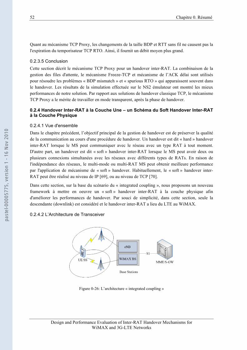
52 Chapitre 0. Résumé
Design and Performance Evaluation of Inter-RAT Handover Mechanisms for WiMAX and 3G-LTE Networks
Quant au mécanisme TCP Proxy, les changements de la taille BDP et RTT sans fil ne causent pas la l'expiration du temporisateur TCP RTO. Ainsi, il fournit un débit moyen plus grand.
0.2.3.5 Conclusion Cette section décrit le mécanisme TCP Proxy pour un handover inter-RAT. La combinaison de la gestion des files d'attente, le mécanisme Freeze-TCP et mécanisme de l’ACK délai sont utilisés pour résoudre les problèmes « BDP mismatch » et « spurious RTO » qui apparaissent souvent dans le handover. Les résultats de la simulation effectuée sur le NS2 émulateur ont montré les mieux performances de notre solution. Par rapport aux solutions de handover classique TCP, le mécanisme TCP Proxy a le mérite de travailler en mode transparent, après la phase de handover.
0.2.4 Handover Inter-RAT à la Couche Une – un Schéma du Soft Handover Inter-RAT à la Couche Physique
0.2.4.1 Vue d'ensemble Dans le chapitre précédent, l’objectif principal de la gestion de handover est de préserver la qualité de la communication au cours d'une procédure de handover. Un handover est dit « hard » handover inter-RAT lorsque le MS peut communiquer avec le réseau avec un type RAT à tout moment. D'autre part, un handover est dit « soft » handover inter-RAT lorsque le MS peut avoir deux ou plusieurs connexions simultanées avec les réseaux avec différents types de RATs. En raison de l'indépendance des réseaux, le multi-mode ou multi-RAT MS peut obtenir meilleure performance par l'application de mécanisme de « soft » handover. Habituellement, le « soft » handover inter-RAT peut être réalisé au niveau de IP [69], ou au niveau de TCP [70].
Dans cette section, sur la base du scénario du « integrated coupling », nous proposons un nouveau framework à mettre en oeuvre un « soft » handover inter-RAT à la couche physique afin d'améliorer les performances de handover. Par souci de simplicité, dans cette section, seule la descendante (downlink) est considéré et le handover inter-RAT a lieu du LTE au WiMAX.
0.2.4.2 L’Architecture de Transceiver
Figure 0-26: L’architecture « integrated coupling »
past
el-0
0005
775,
ver
sion
1 -
16 N
ov 2
010
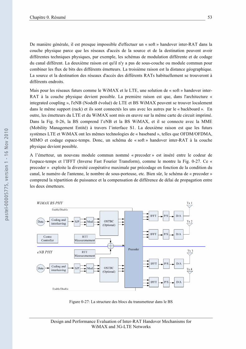
Chapitre 0. Résumé
Design and Performance Evaluation of Inter-RAT Handover Mechanisms for WiMAX and 3G-LTE Networks
53
De manière générale, il est presque impossible d'effectuer un « soft » handover inter-RAT dans la couche physique parce que les réseaux d'accès de la source et de la destination peuvent avoir différentes techniques physiques, par exemple, les schémas de modulation différente et de codage du canal différent. La deuxième raison est qu'il n'y a pas de sous-couche ou module commun pour combiner les flux de bits des différents émetteurs. La troisième raison est la distance géographique. La source et la destination des réseaux d'accès des différents RATs habituellement se trouveront à différents endroits.
Mais pour les réseaux futurs comme le WiMAX et le LTE, une solution de « soft » handover inter-RAT à la couche physique devient possible. La première raison est que, dans l'architecture « integrated coupling », l'eNB (NodeB évolué) de LTE et BS WiMAX peuvent se trouver localement dans le même support (rack) et ils sont connectés les uns avec les autres par le « backboard ». En outre, les émetteurs du LTE et du WiMAX sont mis en œuvre sur la même carte de circuit imprimé. Dans la Fig. 0-26, la BS comprend l’eNB et la BS WiMAX, et il se connecte avec la MME (Mobility Management Entité) à travers l’interface S1. La deuxième raison est que les futurs systèmes LTE et WiMAX ont les mêmes technologies de « baseband », telles que OFDM/OFDMA, MIMO et codage espace-temps. Donc, un schéma de « soft » handover inter-RAT à la couche physique devient possible.
A l’émetteur, un nouveau module commun nommé « precoder » est inséré entre le codeur de l'espace-temps et l’IFFT (Inverse Fast Fourier Transform), comme le montre la Fig. 0-27. Ce « precoder » exploite la diversité coopérative maximale par précodage en fonction de la condition du canal, le numéro de l'antenne, le nombre de sous-porteuse, etc. Bien sûr, le schéma de « precoder » comprend la répartition de puissance et la compensation de différence de délai de propagation entre les deux émetteurs.
Figure 0-27: La structure des blocs du transmetteur dans le BS
past
el-0
0005
775,
ver
sion
1 -
16 N
ov 2
010
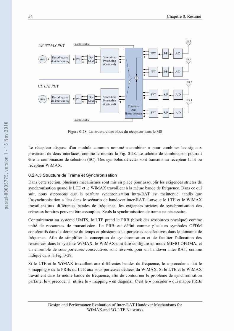
54 Chapitre 0. Résumé
Design and Performance Evaluation of Inter-RAT Handover Mechanisms for WiMAX and 3G-LTE Networks
Figure 0-28: La structure des blocs du récepteur dans le MS
Le récepteur dispose d'un module commun nommé « combiner » pour combiner les signaux provenant de deux interfaces, comme le montre la Fig. 0-28. Le schéma de combinaison pourrait être la combinaison de sélection (SC). Des symboles détectés sont transmis au récepteur LTE ou récepteur WiMAX.
0.2.4.3 Structure de Trame et Synchronisation Dans cette section, plusieurs mécanismes sont mis en place pour assouplir les exigences strictes de synchronisation quand le LTE et le WiMAX travaillent à la même bande de fréquence. Dans ce qui suit, nous supposons que la parfaite synchronisation intra-RAT est maintenue, tandis que l’asynchronisation a lieu dans le scénario de handover inter-RAT. Lorsque le LTE et le WiMAX travaillent aux différentes bandes de fréquence, les exigences strictes de synchronisation des créneaux horaires peuvent être assouplies. Seuls la synchronisation de trame est nécessaire.
Contrairement au système UMTS, le LTE prend le PRB (block des ressources physique) comme unité de ressources de transmission. Le PRB est défini comme plusieurs symboles OFDM consécutifs dans le domaine du temps et plusieurs sous-porteuses consécutives dans le domaine de fréquence. Afin de simplifier la conception de synchronisation et de faciliter l'allocation des ressources dans le système WiMAX, le WiMAX doit être configuré en mode MIMO-OFDMA, et un ensemble de sous-porteuses consécutives sont réservés pour un handover inter-RAT, comme indiqué dans la Fig. 0-29.
Si le LTE et le WiMAX travaillent aux différentes bandes de fréquence, le « precoder » fait le « mapping » de la PRBs du LTE aux sous-porteuses dédiées du WiMAX. Si le LTE et le WiMAX travaillent dans la même bande de fréquence, afin de contourner le problème de synchronisation parfaite, le « precoder » utilise le « mapping » en diagonal. C'est le « precoder » qui mappe PRBs
past
el-0
0005
775,
ver
sion
1 -
16 N
ov 2
010
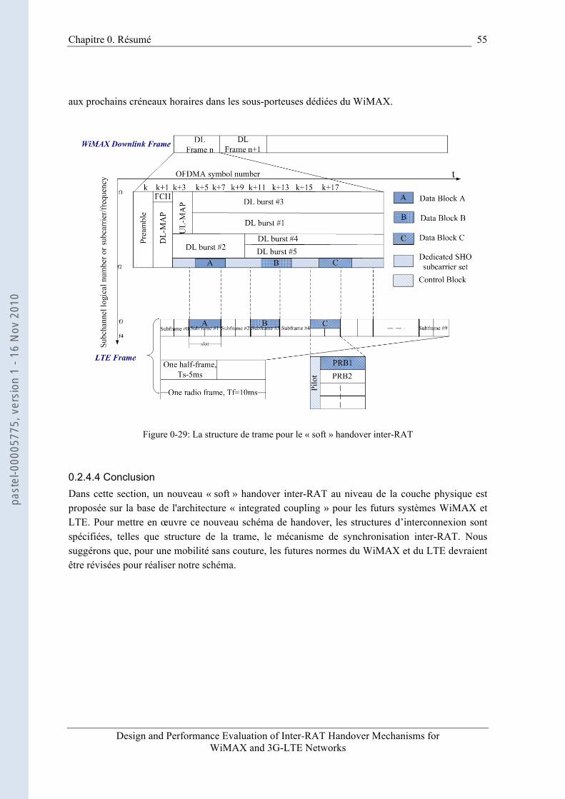
Chapitre 0. Résumé
Design and Performance Evaluation of Inter-RAT Handover Mechanisms for WiMAX and 3G-LTE Networks
55
aux prochains créneaux horaires dans les sous-porteuses dédiées du WiMAX.
Figure 0-29: La structure de trame pour le « soft » handover inter-RAT
0.2.4.4 Conclusion Dans cette section, un nouveau « soft » handover inter-RAT au niveau de la couche physique est proposée sur la base de l'architecture « integrated coupling » pour les futurs systèmes WiMAX et LTE. Pour mettre en œuvre ce nouveau schéma de handover, les structures d’interconnexion sont spécifiées, telles que structure de la trame, le mécanisme de synchronisation inter-RAT. Nous suggérons que, pour une mobilité sans couture, les futures normes du WiMAX et du LTE devraient être révisées pour réaliser notre schéma.
past
el-0
0005
775,
ver
sion
1 -
16 N
ov 2
010
Design and Performance Evaluation of Inter-RAT Handover Mechanisms for WiMAX and 3G-LTE Networks
CHAPTER 1 INTRODUCTION
In future mobile networks, different radio access technologies, such as GSM/GPRS, UMTS, WIFI and WiMAX, will have to coexist. A multi-mode or multi-RAT mobile station may have the demand of roaming among these networks. Hence, the interworking of these heterogeneous networks becomes necessary for the purpose of providing seamless mobility services for these mobile stations. The seamless mobility services not only realize continuous service transfers on the network side, but also make serving network change procedure transparent to ongoing sessions.
Seamless mobility brings many implementation and deployment challenges. For example, different handover management solutions and corresponding service qualities lead to different implementation difficulties. In addition, in order to satisfy mobility service requirements, an operator must take into account the network interworking architecture, such as loose coupling, tight coupling and integrated coupling architectures. Furthermore, implementing the unified access control functions is not only a technical problem but also a policy problem.
In our research project on the convergence of future mobile networks in the scope of B3G/4G, we undertake the challenge of interconnecting UMTS (Universal Mobile Telecommunications System) network with WiMAX (Worldwide Interoperability for Microwave Access) network. This network convergence can extend mobile user’s mobility range and provide better mobility service quality. In order to implement the integration of these two networks and realize seamless mobility, we plan to start with above two most important issues - vertical handover management and interworking architecture. Unlike other conventional research projects, the outcomes of this project shall not only be publishable but also be applicable to engineering implementation.
In this thesis, since we only consider the handover between heterogeneous networks, we use terms “vertical handover”, “inter-RAT handover” and “handover” interchangeably. Only the downlink traffics are considered.
1.1 Background and Motivation
1.1.1 Vertical Handover Management At present, a variety of mobility management solutions in heterogeneous networks have been proposed, such as Mobile IPv6 (MIPv6) [1], Fast Handover for Mobile IPv6 (FMIPv6) [4], Stream Control Transmission Protocol (SCTP) [70], inter-RAT handover of 3GPP [40][43] and IEEE 802.21 [79]. MIPv6 [1], a network layer solution, supports host mobility by implementing movement detection, IP address configuration and location update procedures. However, many experiments and simulations have shown its limitations in maintaining the continuity of ongoing
past
el-0
0005
775,
ver
sion
1 -
16 N
ov 2
010
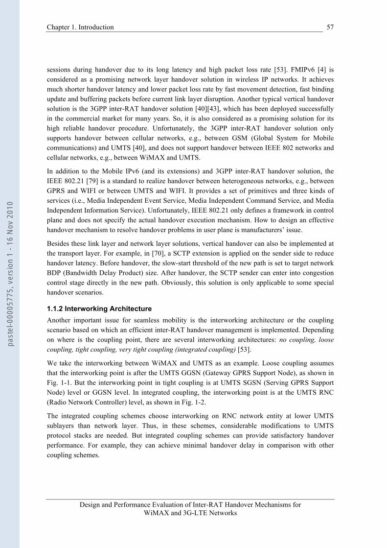
Chapter 1. Introduction
Design and Performance Evaluation of Inter-RAT Handover Mechanisms for WiMAX and 3G-LTE Networks
57
sessions during handover due to its long latency and high packet loss rate [53]. FMIPv6 [4] is considered as a promising network layer handover solution in wireless IP networks. It achieves much shorter handover latency and lower packet loss rate by fast movement detection, fast binding update and buffering packets before current link layer disruption. Another typical vertical handover solution is the 3GPP inter-RAT handover solution [40][43], which has been deployed successfully in the commercial market for many years. So, it is also considered as a promising solution for its high reliable handover procedure. Unfortunately, the 3GPP inter-RAT handover solution only supports handover between cellular networks, e.g., between GSM (Global System for Mobile communications) and UMTS [40], and does not support handover between IEEE 802 networks and cellular networks, e.g., between WiMAX and UMTS.
In addition to the Mobile IPv6 (and its extensions) and 3GPP inter-RAT handover solution, the IEEE 802.21 [79] is a standard to realize handover between heterogeneous networks, e.g., between GPRS and WIFI or between UMTS and WIFI. It provides a set of primitives and three kinds of services (i.e., Media Independent Event Service, Media Independent Command Service, and Media Independent Information Service). Unfortunately, IEEE 802.21 only defines a framework in control plane and does not specify the actual handover execution mechanism. How to design an effective handover mechanism to resolve handover problems in user plane is manufacturers’ issue.
Besides these link layer and network layer solutions, vertical handover can also be implemented at the transport layer. For example, in [70], a SCTP extension is applied on the sender side to reduce handover latency. Before handover, the slow-start threshold of the new path is set to target network BDP (Bandwidth Delay Product) size. After handover, the SCTP sender can enter into congestion control stage directly in the new path. Obviously, this solution is only applicable to some special handover scenarios.
1.1.2 Interworking Architecture Another important issue for seamless mobility is the interworking architecture or the coupling scenario based on which an efficient inter-RAT handover management is implemented. Depending on where is the coupling point, there are several interworking architectures: no coupling, loose coupling, tight coupling, very tight coupling (integrated coupling) [53].
We take the interworking between WiMAX and UMTS as an example. Loose coupling assumes that the interworking point is after the UMTS GGSN (Gateway GPRS Support Node), as shown in Fig. 1-1. But the interworking point in tight coupling is at UMTS SGSN (Serving GPRS Support Node) level or GGSN level. In integrated coupling, the interworking point is at the UMTS RNC (Radio Network Controller) level, as shown in Fig. 1-2.
The integrated coupling schemes choose interworking on RNC network entity at lower UMTS sublayers than network layer. Thus, in these schemes, considerable modifications to UMTS protocol stacks are needed. But integrated coupling schemes can provide satisfactory handover performance. For example, they can achieve minimal handover delay in comparison with other coupling schemes.
past
el-0
0005
775,
ver
sion
1 -
16 N
ov 2
010
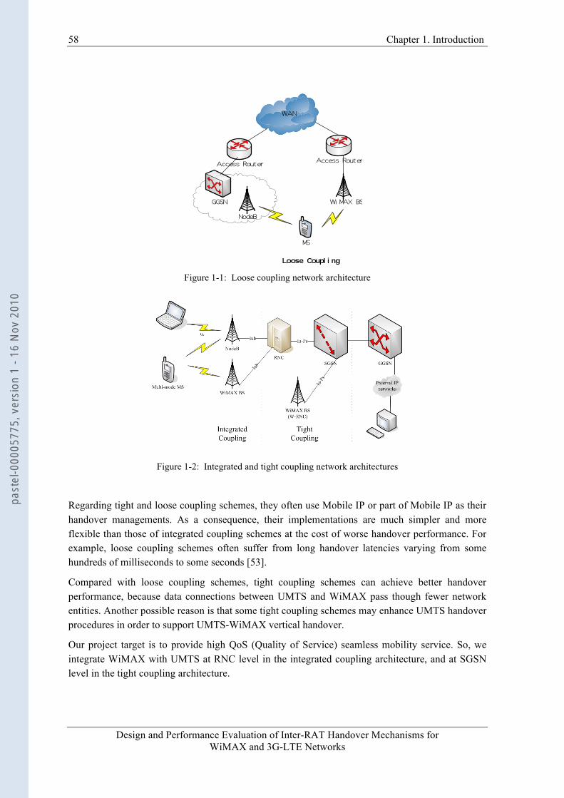
58 Chapter 1. Introduction
Design and Performance Evaluation of Inter-RAT Handover Mechanisms for WiMAX and 3G-LTE Networks
Figure 1-1: Loose coupling network architecture
Figure 1-2: Integrated and tight coupling network architectures
Regarding tight and loose coupling schemes, they often use Mobile IP or part of Mobile IP as their handover managements. As a consequence, their implementations are much simpler and more flexible than those of integrated coupling schemes at the cost of worse handover performance. For example, loose coupling schemes often suffer from long handover latencies varying from some hundreds of milliseconds to some seconds [53].
Compared with loose coupling schemes, tight coupling schemes can achieve better handover performance, because data connections between UMTS and WiMAX pass though fewer network entities. Another possible reason is that some tight coupling schemes may enhance UMTS handover procedures in order to support UMTS-WiMAX vertical handover.
Our project target is to provide high QoS (Quality of Service) seamless mobility service. So, we integrate WiMAX with UMTS at RNC level in the integrated coupling architecture, and at SGSN level in the tight coupling architecture.
past
el-0
0005
775,
ver
sion
1 -
16 N
ov 2
010
Chapter 1. Introduction
Design and Performance Evaluation of Inter-RAT Handover Mechanisms for WiMAX and 3G-LTE Networks
59
1.1.3 TCP Specific Problems Whatever the handover management and interworking architecture are, the target of the handover solution is to provide a suitable QoS for the mobile user. Nowadays the majority of Internet services, such as FTP, HTTP, or E-Mail, are supported by TCP protocol. So it is necessary to extensively study the impacts of vertical handover on TCP performance. The typical problems during the vertical handover period have been indicated by numerous references, which usually are long handover latency, BDP mismatch, delay spikes, packet losses, premature timeout, false fast retransmission and spurious RTO (Retransmission TimeOut) [60]. Actually, all these problems cannot be resolved by only one solution at a time. For instance, the conventional handover management protocols only aim at achieving low packet loss and/or reducing handover latency at IP layer (e.g., FMIPv6), at link layer (e.g., 3GPP inter-RAT handover), at TCP layer (e.g., SCTP extensions), even at application layer (e.g., SIP). As for other problems, since some general solutions [60-66] are proposed at TCP layer, they do not depend on a special interworking architecture or lower layer handover management mechanism. However, these solutions demand significant modifications to the existing TCP protocol stacks [60][61], or suffer from the packet loss problem during handover [62], or need precise “warning period” calculation [63], or require IP layer soft-handover procedure [64].
1.2 Contributions In our project on UMTS-WiMAX interworking, we propose a new total solution with cross-layer mechanism to resolve above open problems in the integrated and tight coupling architectures. To the best of our knowledge, our solution is the first total solution aiming at several typical inter-RAT handover problems at the same time. To facilitate the research work, we group these problems into two typical types: the packet losses/long handover latency, and BDP mismatch/spurious RTO. For the first type problems, we propose a novel inter-RAT handover management protocol with inter-system retransmission mechanism at a common Layer 2 sublayer. As for the second type problems, we propose to utilize the TCP Proxy architecture to smooth the BDP and RTO differences of two wireless networks. Our contributions can be summarized as follows:
• We follow a timing diagram methodology [26] to analyze the FMIPv6 handover performance under the assumption of perfect lower layers (i.e., no packets/frames stored at MAC/PHY layer during a handover) and there are a couple of cross-layer triggers between the IP layer and link layer. We identify the conditions in which the best performance can be achieved and what are the limitations when the FMIPv6 is used as the vertical handover protocol.
• Based on analysis of FMIPv6, we propose a novel Layer 2 inter-RAT handover solution by introducing a new common sublayer named IW (InterWorking) sublayer and retransmission mechanism to resolve the first type of inter-RAT handover problems (i.e., packet losses/long handover latency) in the integrated and tight coupling architectures.
• Compared with the buffering-and-forwarding context transfer scheme of the FMIPv6, the retransmission mechanism at IW sublayer has the benefits of shorter handover latency and zero packet loss, as shown in network simulation results. The simulation also demonstrates
past
el-0
0005
775,
ver
sion
1 -
16 N
ov 2
010
60 Chapter 1. Introduction
Design and Performance Evaluation of Inter-RAT Handover Mechanisms for WiMAX and 3G-LTE Networks
that the packets lost at lower layers during a handover period, which are often omitted in the FMIPv6 performance analysis [4][5], can degrade FMIPv6 handover performance. We also compare the handover performance of retransmission mechanism with that of other context transfer schemes, such as SDU Reconstruction [57] and R-LLC [56]. The simulation results also show their limitations and the advantages of the retransmission mechanism.
• In addition, two kinds of snoop agents named TCP Proxy and enhanced TCP Proxy are introduced on the RNC to resolve the second type problems. The TCP Proxy is designed for the frequent handover scenarios. The enhanced TCP Proxy, which is in possession of the cross-layer mechanism, is designed for the occasional handover scenarios.
• Generally speaking, the lower layer the handover solution is realized at, the better handover performance could be achieved. All the conventional inter-RAT handover solutions are realized at Layer 2 or above due to the impossibility of common module at physical layer and geographical distance of source and target access networks. But for the future LTE and WiMAX systems in the integrated coupling architecture, this is not the case, because they have some common physical techniques, such as MIMO and OFDM. Two common modules named precoder and combiner are proposed respectively on base stations and on mobile station at physical layer to exploit the maximum diversity of two RATs. This inter-RAT handover physical scheme is totally new to the best of our knowledge.
1.3 Organization of the Thesis Following this first introductory chapter, the thesis is structured as follows:
Chapter 2 overviews some vertical handover solutions realized at IP layer, especially the Mobile IP and its extensions. The simulation and experiment results of the vertical handover solutions based on Mobile IP are also summarized to get a general idea of their performance. We find that these solutions suffer from long handover delay and possible packet losses, which are not acceptable to high QoS demanding services. Thus, in order to find out the limitations of the Layer 3 handover solutions, we perform the timing analysis for one typical Mobile IP solution- FMIPv6. The conclusions of the timing analysis motivate us to propose a better handover solution at Layer 2.
Chapter 3 describes a new common IW sublayer located on top of PDCP (Packet Data Convergence Protocol) sublayer of UMTS and MAC sublayer of WiMAX. Its working mechanisms and signalling procedures in the tight and integrated coupling architectures are also specified in detail. The simulation results demonstrate its better handover performance than that of Layer 3 solutions.
Chapter 4 introduces a new snoop agent - TCP Proxy, which locates on top of IW sublayer, to resolve some typical handover problems of the TCP traffic. These problems, such as BDP mismatch and spurious RTO, cannot be resolved at the same time by other conventional solutions.
Chapter 5 explores a totally new soft handover physical layer scheme. The future LTE and WiMAX systems have some common physical technologies, such as MIMO and OFDM. In the
past
el-0
0005
775,
ver
sion
1 -
16 N
ov 2
010
Chapter 1. Introduction
Design and Performance Evaluation of Inter-RAT Handover Mechanisms for WiMAX and 3G-LTE Networks
61
integrated coupling architecture, we propose two common modules, a precoder on base stations and a combiner on a mobile station, to investigate the possibility of soft inter-RAT handover.
Finally, Chapter 6 concludes our thesis and gives a discussion of the achieved work and highlights the future research directions.
past
el-0
0005
775,
ver
sion
1 -
16 N
ov 2
010
Design and Performance Evaluation of Inter-RAT Handover Mechanisms for WiMAX and 3G-LTE Networks
Part I
Inter-RAT Handover At Layer Three
past
el-0
0005
775,
ver
sion
1 -
16 N
ov 2
010
Design and Performance Evaluation of Inter-RAT Handover Mechanisms for WiMAX and 3G-LTE Networks
CHAPTER 2 VERTICAL HANDOVER AT LAYER THREE
This chapter describes the working principles, signaling procedures and performance of the Mobile IP and its extensions. Because of limitations of conventional Mobile IP [1][2], such as long handover latency and high packet loss rate, IETF (Internet Engineering Task Force) proposes various Mobile IP extensions. For example, the Fast Handovers for Mobile IPv6 (FMIPv6) [4] reduces the handover latency and the packet losses. Hierarchical Mobile IP (HMIPv6) [6] reduces the signaling overhead in the IP core network. A variety of experiments and simulations show that, although these Mobile IP extensions achieve better performance than original Mobile IP, some metrics still are not acceptable to real-time streams. Therefore, many modifications and optimizations are performed to these Mobile IP extensions, e.g., adding multi-casting during inter-domain handover to HMIPv6 [21]. These modifications may be integrated into the seamless roaming solutions in future wireless IP networks. Furthermore, experiment and simulation results confirm that the Layer 3 handover solution itself cannot significantly reduce handover latency and packet losses. For this reason, a promising technique named Layer 2 trigger is introduced into the Layer 3 IP handover procedure.
With these improvements and triggers, perhaps one of the Mobile IP extensions would be considered as a candidate for the future heterogeneous wireless networks such as Beyond 3G or 4G. So, we investigate a promising vertical handover solution - FMIPv6 to check whether it is really qualified for this task. The FMIPv6 aims at reducing the long handover latency in Mobile IPv6 by fast movement detection and fast binding update. Furthermore, it also reduces packet losses by buffering packets prior to link layer handover. Due to uncertain link layer triggering time, however, the buffer mechanism sometimes introduces unacceptable handover latency for real-time streams such as Voice over IP (VoIP). In addition, if it’s the mobile node (MN) that makes the handover decision, FMIPv6 also suffers from uncertainty of handover target, which is unfavourable to TCP traffics such as FTP. In order to eliminate these negative effects, we suggest that FMIPv6 should operate in predictive mode under the control of network for TCP traffics. Concerning the VoIP traffic, in terms of the handover latency and packet loss rate requirements, a proposed hybrid mode is chosen adaptively. Numerical simulation results for the VoIP traffic demonstrate obvious performance improvements in terms of call drop rate and a new metric called packet cost.
In this chapter, we prefer to use the term “handover” rather than “handoff” except that the latter has been used by IETF. The terms “Layer 3” and “IP layer” are used interchangeably, because in wireless IP network, they have the same meaning. Since only Layer 3 solutions are discussed in this chapter, we use “inter-domain handover” instead of “inter-RAT handover”, because the former term is often used in Mobile IP.
past
el-0
0005
775,
ver
sion
1 -
16 N
ov 2
010
64 Chapter 2. Vertical Handover At Layer Three
Design and Performance Evaluation of Inter-RAT Handover Mechanisms for WiMAX and 3G-LTE Networks
2.1 Mobile IP and Its Extensions
2.1.1 Introduction The primary purpose of Mobile IP [1][2] is to support MN mobility in the IP network, because the classical IP addressing mechanism binds MN’s identifier with its current network location. Several new network entities, IP address types and routing mechanisms are introduced into Mobile IP to keep IP layer connectivity when a MN changes its network location. Since most future mobile networks are based on IP technology, the Mobile IP becomes the default choice of IP mobility management.
Unfortunately, Mobile IP suffers from several drawbacks, such as high packet loss rate and long disruption/blackout period when a MN disrupts its current network attachment and is attached to a new network. These drawbacks can impact even disrupt ongoing sessions. If the MN roams into a network with a different access technology (inter-domain or inter-RAT handover), these drawbacks may become more serious. Therefore, it is said that Mobile IP is a path update protocol rather than a handover management protocol [3]. Because of these drawbacks, many Mobile IP extensions have been proposed in IETF society to shorten disruption time and reduce packet loss rate. Whether these extensions can offer a seamless mobility is still an open problem.
In this chapter, we will investigate Mobile IP and its extensions in the context of wireless IP networks. In addition, a variety of simulations and experiments will be surveyed. We focus on two important measurement metrics of handover quality: handover latency and packet loss rate. Around these two metrics, we will study the handover performance of these Layer 3 handover solutions, understand their limitations, tell what kinds of optimizations or modifications to these solutions are needed and find out what features a smooth and seamless handover solution shall have.
Moreover, since many analytical and simulation results show that the Layer 3 handover disruption duration cannot be reduced significantly only by optimizing Layer 3 handover solution itself, applying Layer 2 triggers becomes a reasonable way to solve this problem. Hence, the Layer 2 trigger mechanism is also introduced in this chapter.
Section 2.1.2 gives a brief introduction to Mobile IPv4 and Mobile IPv6. Then, in section 2.1.3 we investigate handover simulations and experiments presented in literatures relevant to the inter-domain handover, and make a comparative analysis according to handover latency metric. In section 2.1.4, the Layer 2 triggers are introduced to improve Mobile IP handover performance. Finally, we draw some conclusions about Mobile IP and its extension in section 2.1.5.
2.1.2 Protocol Overview
2.1.2.1 Mobile IPv4 (MIPv4) [2] Mobile IPv4 [2] is designed to provide a way to support MN mobility. A MN periodically receives the agent advertisement messages from Foreign Agents (FAs) when it moves into a foreign network. In these messages, care-of addresses (CoAs) of FAs are included. If the MN finds out that received FA CoAs are different from the former one, MN is aware that it is inside new foreign networks. So, it sends a new FA CoA in a registration request message to his Home Agent (HA) to
past
el-0
0005
775,
ver
sion
1 -
16 N
ov 2
010
Chapter 2. Vertical Handover At Layer Three
Design and Performance Evaluation of Inter-RAT Handover Mechanisms for WiMAX and 3G-LTE Networks
65
update its FA CoA record. Afterwards, all packets sent by Correspond Node (CN) to the MN are intercepted by the HA in the home network. Then these packets are forwarded by the HA to MN’s new FA through a tunnel. The tunneled packets are de-tunnelled and forwarded to the MN by the new FA. In this way, the IP connectivity is maintained and ongoing communication sessions are not disrupted.
2.1.2.2 Mobile IPv6 (MIPv6) [1] Mobile IPv4 suffers from inefficient triangle routing problem because packets from a CN are first forwarded to an HA then to a MN. Mobile IPv6 [1] avoids this problem by MN informing both CN and HA of the CoA. So, packets can be delivered from the CN to the MN directly. In addition, Mobile IPv6 can operate without the support of FA. A MN can form a CoA by itself after it receives subnet prefix information from an Access Router (AR). However, before sending this New CoA (NCoA) to both CN and HA, the MN must make sure of this CoA uniqueness by performing time-consuming procedures, such as duplication address detection (DAD). The long latency and packet losses during these procedures may be unacceptable to delay-stringent real-time traffics.
2.1.2.3 Fast Handovers for Mobile IPv6 (FMIPv6) [4][5] In [4][5], Koodli proposes a protocol to reduce handover latency and eliminate packet losses in Mobile IPv6. It achieves these goals through fast movement detection, fast binding update and buffer mechanisms. We will go into details of these FMIPv6 working mechanisms in section 2.2.
2.1.2.4 Hierarchical Mobile IPv6 Mobility Management (HMIPv6) [6] In order to reduce MIPv6 signaling cost, Soliman [6] proposes an intermediate router named Mobile Anchor Point (MAP) in between MN and HA/CNs. When a MN first moves into a new MAP domain, it shall send registration request messages to its HA and CNs. When the MN roams inside this local MAP domain, it only performs regional registration with this local MAP instead of remote HA and CNs. All packets from CNs are tunneled to this local MAP and then rerouted to the MN. Hence both signaling transmission delay and overhead are reduced considerably.
2.1.2.5 Fast Handover for Hierarchical Mobile IPv6 (F-HMIPv6) [7] The HMIPv6 [6] reduces the signaling overhead and transmission delay, but it omits the delay caused by NCoA validation. On the contrary, FMIPv6 eliminates movement detection delay and NCoA validation delay regardless of signaling overhead. Jung [7] proposes a combination scheme of FMIPv6 and HMIPv6, which is renamed Fast Handover for Hierarchical Mobile IPv6 (F-HMIPv6). In F-HMIPv6, handover signaling is exchanged between MAP and MN instead of between PAR/NAR and MN. Data packets from HA or CNs are forwarded by MAP to the PAR/NAR then to the MN.
2.1.2.6 Mobile IPv4 Regional Registration (HMIPv4) [13] A hierarchical handover protocol based on IPv4 is proposed in [13], which is named Mobile IPv4 Regional Registration or Hierarchical Mobile IPv4 (HMIPv4). As a counterpart of MAP in HMIPv6, Gateway Foreign Agent (GFA) is introduced into HMIPv4 to reduce registration signaling overhead and transmission delay. In a GFA domain, the GFA address advertised by FAs,
past
el-0
0005
775,
ver
sion
1 -
16 N
ov 2
010
66 Chapter 2. Vertical Handover At Layer Three
Design and Performance Evaluation of Inter-RAT Handover Mechanisms for WiMAX and 3G-LTE Networks
is acquired by MN and sent to HA as a CoA in a registration request message when the MN first enters into the GFA domain. If the MN roams inside the domain, the MN only informs GFA of its new address with regional registration messages. The packets from HA or CNs are tunneled to GFA then are forwarded to MN.
2.1.2.7 Mobile IPv4 Fast Handovers (FMIPv4) [14] FMIPv4 [14] proposes a fast handover protocol on the basis of Mobile IPv4. In comparison with FMIPv6, FMIPv4 uses PFA (Previous FA) and NFA (New FA) instead of PAR and NAR. A MN either uses co-located CoA (through DHCP) or simply uses FA CoA to avoid unnecessary neighbor discovery procedures in FMIPv6. Hence, the working flows and message formats of FMIPv4 are a bit different from those of FMIPv6.
2.1.2.8 Context Transfer [5] Short handover latency and low packet losses do not necessarily make handover procedure transparent to upper layers. Reference [5] indicates the importance of contexts that shall be transferred from one AR to another AR for a seamless handover. The contexts often refer to undelivered packets, QoS parameters, header compression, security parameters etc. For example, if packets of a real-time stream are forwarded from PAR to NAR, they maybe useless due to unknown header compression format. Hence, for providing a seamless service in future heterogeneous networks, the context transfer scheme shall be tightly integrated into the mobility management protocol.
2.1.2.9 Synthesis In summary, the Mobile IP generally has the following drawbacks:
• Mobile IPv4 has triangular routing problem that results in extra delay for packet delivery. Although this problem has be fixed in Mobile IPv6, but newly introduced neighbor discovery procedures still lead to a long latency handover.
• When a MN moves into a new foreign network and obtains a new CoA, before it informs the HA or CNs of its changes, packets destined for old CoA and in flight are lost.
• With the increase of distance between MN and its HA, registration signaling delay increases.
Because of these problems, it is said that Mobile IP is a path update protocol rather than a handover management protocol [3]. Therefore, FMIPv6 is proposed to reduce handover latency and packet losses during a handover, while HMIPv6 decreases location update latency and overhead by introducing an intermediate MAP router. The F-HMIPv6 achieves both advantages by combining both schemes’ approaches.
2.1.3 Mobile IP Handover Performance Evaluation The working mechanisms of Mobile IP and its extensions have been described in the former sub-clause. Then, investigating their performance in experiments or simulations becomes necessary. In this sub-clause, several publications about basic Mobile IP and its extensions will be discussed in
past
el-0
0005
775,
ver
sion
1 -
16 N
ov 2
010
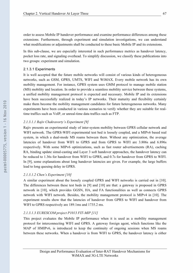
Chapter 2. Vertical Handover At Layer Three
Design and Performance Evaluation of Inter-RAT Handover Mechanisms for WiMAX and 3G-LTE Networks
67
order to assess Mobile IP handover performance and examine performance differences among these extensions. Furthermore, through experiment and simulation investigations, we can understand what modifications or adjustments shall be conducted to these basic Mobile IP and its extensions.
In this sub-clause, we are especially interested in such performance metrics as handover latency, pocket loss rate, and signaling overhead. To simplify discussion, we classify these publications into two groups: experiment and simulation.
2.1.3.1 Experiments It is well accepted that the future mobile networks will consist of various kinds of heterogeneous networks, such as GSM, GPRS, UMTS, WIFI and WiMAX. Every mobile network has its own mobility management. For instance, GPRS system uses GMM protocol to manage mobile station (MS) mobility and location. In order to provide a seamless mobility service between these systems, a unified mobility management protocol is expected and necessary. Mobile IP and its extensions have been successfully realized in today’s IP networks. Their maturity and flexibility certainly make them become the mobility management candidates for future heterogeneous networks. Many experiments have been conducted in various scenarios to verify whether they are suitable for real-time traffics such as VoIP, or unreal-time data traffics such as FTP.
2.1.3.1.1 Rajiv Chakravorty’s Experiment [9] Rajiv presents an experimental study of inter-system mobility between GPRS cellular network and WIFI network. The GPRS-WIFI experimental test bed is loosely coupled, and a MIPv6 based real system, in which a dual-mode MS roams between them. Without any optimization, the average latencies of handover from WIFI to GPRS and from GPRS to WIFI are 3.806s and 6.896s respectively. With some MIPv6 optimizations, such as fast router advertisements (RA), caching RA, binding update simul-casting and Layer 3 soft handover approaches, the handover latency can be reduced to 1.36s for handover from WIFI to GPRS, and 0.7s for handover from GPRS to WIFI. In [9], some explanations about long handover latencies are given. For example, the large buffers lead to long queuing delay in GPRS.
2.1.3.1.2 Chen’s Experiment [10] A similar experiment about the loosely coupled GPRS and WIFI networks is carried out in [10]. The differences between these test beds in [9] and [10] are that: a gateway is proposed in GPRS network in [10], which provides GGSN, HA, and FA functionalities as well as connects GPRS network with WIFI network. Besides, the mobility management protocol is MIPv4 in [10]. The experiment results show that the latencies of handover from GPRS to WIFI and handover from WIFI to GPRS respectively are 189.1ms and 1735.2 ms.
2.1.3.1.3 EURESCOM project P1013 FIT-MIP [11] This project evaluates the Mobile IP performance when it is used as a mobility management protocol for interconnecting WIFI and GPRS. A gateway foreign agent, which functions like the MAP of HMIPv6, is introduced to keep the continuity of ongoing sessions when MS roams between these networks. When a handover is from WIFI to GPRS, the handover latency is either
past
el-0
0005
775,
ver
sion
1 -
16 N
ov 2
010
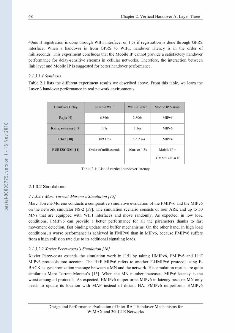
68 Chapter 2. Vertical Handover At Layer Three
Design and Performance Evaluation of Inter-RAT Handover Mechanisms for WiMAX and 3G-LTE Networks
40ms if registration is done through WIFI interface, or 1.5s if registration is done through GPRS interface. When a handover is from GPRS to WIFI, handover latency is in the order of milliseconds. This experiment concludes that the Mobile IP cannot provide a satisfactory handover performance for delay-sensitive streams in cellular networks. Therefore, the interaction between link layer and Mobile IP is suggested for better handover performance.
2.1.3.1.4 Synthesis Table 2.1 lists the different experiment results we described above. From this table, we learn the Layer 3 handover performance in real network environments.
Handover Delay GPRS->WIFI WIFI->GPRS Mobile IP Variant
Rajiv [9] 6.896s 3.806s MIPv6
Rajiv, enhanced [9] 0.7s 1.36s MIPv6
Chen [10] 189.1ms 1735.2 ms MIPv4
EURESCOM [11] Order of milliseconds 40ms or 1.5s Mobile IP +
GMM/Celluar IP
Table 2.1: List of vertical handover latency
2.1.3.2 Simulations
2.1.3.2.1 Marc Torrent-Moreno’s Simulation [15] Marc Torrent-Moreno conducts a comparative simulative evaluation of the FMIPv6 and the MIPv6 on the network simulator NS-2 [59]. The simulation scenario consists of four ARs, and up to 50 MNs that are equipped with WIFI interfaces and move randomly. As expected, in low load conditions, FMIPv6 can provide a better performance for all the parameters thanks to fast movement detection, fast binding update and buffer mechanisms. On the other hand, in high load conditions, a worse performance is achieved in FMIPv6 than in MIPv6, because FMIPv6 suffers from a high collision rate due to its additional signaling loads.
2.1.3.2.2 Xavier Perez-costa’s Simulation [16] Xavier Perez-costa extends the simulation work in [15] by taking HMIPv6, FMIPv6 and H+F MIPv6 protocols into account. The H+F MIPv6 refers to another F-HMIPv6 protocol using F-BACK as synchronization message between a MN and the network. His simulation results are quite similar to Marc Torrent-Moreno’s [15]. When the MN number increases, MIPv6 latency is the worst among all protocols. As expected, HMIPv6 outperforms MIPv6 in latency because MN only needs to update its location with MAP instead of distant HA. FMIPv6 outperforms HMIPv6
past
el-0
0005
775,
ver
sion
1 -
16 N
ov 2
010

Chapter 2. Vertical Handover At Layer Three
Design and Performance Evaluation of Inter-RAT Handover Mechanisms for WiMAX and 3G-LTE Networks
69
because handover is prepared before link disruption. H+F MIPv6 performs best among all protocols, since this protocol not only makes MN prepare handover in advance but also reduces signaling delay in wired network.
2.1.3.2.3 R. Hsieh’ Simulation [17] Different from above simulations, R. Hsieh’s simulation focuses on the impacts of the Layer 3 handover latency on the end-to-end TCP flow. He carries out a comparative study of MIPv6, HMIPv6, MIPv6 with fast-handoff mechanism, and HMIPv6 with fast-handoff mechanism. The simulation results indicate that the shorter handover latency does not mean higher average throughput. For example, MIPv6 with fast-handoff mechanism has shorter handover latency but has lower average throughput than HMIPv6 due to packet losses caused by delayed handover.
2.1.3.2.4 Synthesis Simulation results of different scenarios show the obvious advantages of FMIPv6-like protocols (FMIPv6, H+F MIPv6, F-HMIPv6, etc.) over other basic ones in low network load conditions. That is the reason why we are interested in FMIPv6. But for TCP traffics, FMIPv6 probably has worse handover performance due to delayed handover.
2.1.3.3 Protocol Enhancements In this sub-clause, we discuss the modifications and optimizations of Mobile IP and its extensions. It can be seen from previous discussion that every mobility protocol has its drawbacks, such as packet losses in HMIPv6 and high signaling overhead in FMIPv6. Many modifications and optimizations of Mobile IP protocols have been proposed to overcome these drawbacks.
2.1.3.3.1 Smooth Handoff and Route Optimization [18] In [18], Kwon and Gerla propose a Mobile IPv4 protocol with Smooth Handoff and Route Optimization extensions to reduce handover latency. During a handover, after a MN is attached to a new FA (nFA), this nFA sends a binding update message to old FA (oFA) to request it to forward packets destined for the MN to the nFA. Then, the nFA delivers these packets as well as tunneled packets to the MN. Because packets are delivered from nFA and oFA, this handover procedure is called Smooth Handoff in [18]. In addition, a Routing Optimization is also proposed in [18] to avoid triangle routing problem of Mobile IPv4. Upon receipt of the binding update message from nFA, oFA requests the HA to inform CNs of the MN’s NCoA by sending a binding warning message. Then, CNs can route packets directly to nFA.
2.1.3.3.2 FF-HMIP [19] In [19], Gwon proposes a modified FHMIP protocol (FF-HMIP) to reduce handover latency and packet loss rate in an inter-MAP handover. When a MN moves into a new MAP domain, it sends a message to its old MAP as soon as it connects with NAR. Then, the old MAP will tunnel packets destined for the MN to NAR. This procedure ends when MN finishes handover in the new MAP domain and updates NCoA cache in HA.
2.1.3.3.3 S-MIP [20]
past
el-0
0005
775,
ver
sion
1 -
16 N
ov 2
010
70 Chapter 2. Vertical Handover At Layer Three
Design and Performance Evaluation of Inter-RAT Handover Mechanisms for WiMAX and 3G-LTE Networks
In [20], Hsieh proposes a sophisticated S-MIP scheme and makes a comparison among the handover protocols MIPv6, HMIPv6, FMIPv6, FHMIPv6, and S-MIP for TCP traffics. A new network entity named Decision Engine (DE) is proposed for tracking MN’s location and estimating MN’s movement pattern according to MN’s current signal strength and triangulation calculation. Once a MN triggers the handover, handover decision is relayed from DE to the PAR and NAR. Then, PAR and NAR prepare for the incoming handover, e.g., maintain the MN’s binding information in case of stochastic movement pattern, or send packets to MN in case of linear movement pattern. With these mechanisms, the S-MIP scheme achieves shortest handover latency in comparison with other protocols. Hsieh [20] also emphasizes the impacts of the packet loss due to the Layer 2 handover on these Layer 3 handover protocols.
2.1.3.3.4 Multi-Casting [21] In [21], Vivaldi proposes a multi-casting scheme to reduce inter-MAP handover latency. The multi-cast group, which comprises adjacent ARs, is built by current MAP when a MN will move beyond this MAP domain. During a handover, all incoming packets are multi-casted by this MAP to these adjacent ARs. Upon MN’s attachment, the NAR forwards the buffered packets to the MN. However, the signaling overhead and dedicated buffers for the multi-cast group are not evaluated in [21].
2.1.3.3.5 Two-Way Registration [22] Regarding HMIPv4 inter-domain handover, Zhang [22] proposes a two-way registration mechanism to reduce the registration latency. As soon as a MN moves into a new GFA domain, it sends registration request message to its HA, which will be intercepted by the new GFA. Then, the new GFA forwards this message to both HA and the MN’s old GFA. The old GFA feeds back a registration reply message upon receipt of this message. The first received reply message (from HA or old GFA) is forwarded to the MN by new GFA and the latter one is omitted. Hence, this procedure is called two-way registration.
2.1.3.3.6 Synthesis In general, the handover latencies investigated in these proposed schemes depend on different assumptions about the environment, the topology, the link delays, the number of MN, the traffic type, the definition of handover latency, etc. So, it is not possible to directly and fairly compare performance results of these schemes. For this reason, we only list the handover latencies in Table 2-2. This comparison gives us an overview about how long the handover latencies at Layer 3 are in different simulation scenarios.
past
el-0
0005
775,
ver
sion
1 -
16 N
ov 2
010
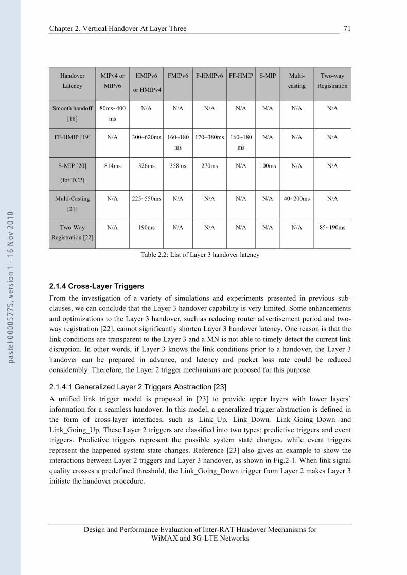
Chapter 2. Vertical Handover At Layer Three
Design and Performance Evaluation of Inter-RAT Handover Mechanisms for WiMAX and 3G-LTE Networks
71
Handover
Latency
MIPv4 or
MIPv6
HMIPv6
or HMIPv4
FMIPv6 F-HMIPv6 FF-HMIP S-MIP Multi-
casting
Two-way
Registration
Smooth handoff
[18]
80ms~400
ms
N/A N/A N/A N/A N/A N/A N/A
FF-HMIP [19] N/A 300~620ms 160~180
ms
170~380ms 160~180
ms
N/A N/A N/A
S-MIP [20]
(for TCP)
814ms 326ms 358ms 270ms N/A 100ms N/A N/A
Multi-Casting
[21]
N/A 225~550ms N/A N/A N/A N/A 40~200ms N/A
Two-Way
Registration [22]
N/A 190ms N/A N/A N/A N/A N/A 85~190ms
Table 2.2: List of Layer 3 handover latency
2.1.4 Cross-Layer Triggers From the investigation of a variety of simulations and experiments presented in previous sub-clauses, we can conclude that the Layer 3 handover capability is very limited. Some enhancements and optimizations to the Layer 3 handover, such as reducing router advertisement period and two-way registration [22], cannot significantly shorten Layer 3 handover latency. One reason is that the link conditions are transparent to the Layer 3 and a MN is not able to timely detect the current link disruption. In other words, if Layer 3 knows the link conditions prior to a handover, the Layer 3 handover can be prepared in advance, and latency and packet loss rate could be reduced considerably. Therefore, the Layer 2 trigger mechanisms are proposed for this purpose.
2.1.4.1 Generalized Layer 2 Triggers Abstraction [23] A unified link trigger model is proposed in [23] to provide upper layers with lower layers’ information for a seamless handover. In this model, a generalized trigger abstraction is defined in the form of cross-layer interfaces, such as Link_Up, Link_Down, Link_Going_Down and Link_Going_Up. These Layer 2 triggers are classified into two types: predictive triggers and event triggers. Predictive triggers represent the possible system state changes, while event triggers represent the happened system state changes. Reference [23] also gives an example to show the interactions between Layer 2 triggers and Layer 3 handover, as shown in Fig.2-1. When link signal quality crosses a predefined threshold, the Link_Going_Down trigger from Layer 2 makes Layer 3 initiate the handover procedure.
past
el-0
0005
775,
ver
sion
1 -
16 N
ov 2
010
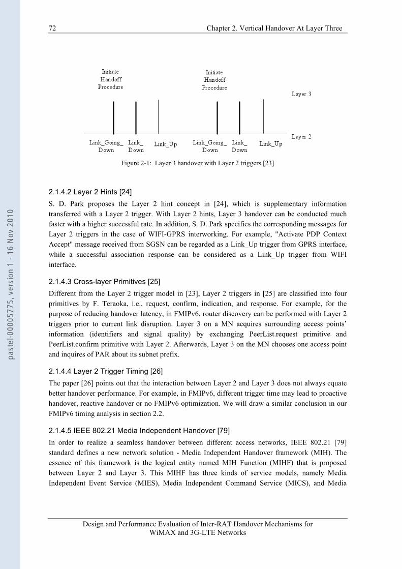
72 Chapter 2. Vertical Handover At Layer Three
Design and Performance Evaluation of Inter-RAT Handover Mechanisms for WiMAX and 3G-LTE Networks
Figure 2-1: Layer 3 handover with Layer 2 triggers [23]
2.1.4.2 Layer 2 Hints [24] S. D. Park proposes the Layer 2 hint concept in [24], which is supplementary information transferred with a Layer 2 trigger. With Layer 2 hints, Layer 3 handover can be conducted much faster with a higher successful rate. In addition, S. D. Park specifies the corresponding messages for Layer 2 triggers in the case of WIFI-GPRS interworking. For example, "Activate PDP Context Accept" message received from SGSN can be regarded as a Link_Up trigger from GPRS interface, while a successful association response can be considered as a Link_Up trigger from WIFI interface.
2.1.4.3 Cross-layer Primitives [25] Different from the Layer 2 trigger model in [23], Layer 2 triggers in [25] are classified into four primitives by F. Teraoka, i.e., request, confirm, indication, and response. For example, for the purpose of reducing handover latency, in FMIPv6, router discovery can be performed with Layer 2 triggers prior to current link disruption. Layer 3 on a MN acquires surrounding access points’ information (identifiers and signal quality) by exchanging PeerList.request primitive and PeerList.confirm primitive with Layer 2. Afterwards, Layer 3 on the MN chooses one access point and inquires of PAR about its subnet prefix.
2.1.4.4 Layer 2 Trigger Timing [26] The paper [26] points out that the interaction between Layer 2 and Layer 3 does not always equate better handover performance. For example, in FMIPv6, different trigger time may lead to proactive handover, reactive handover or no FMIPv6 optimization. We will draw a similar conclusion in our FMIPv6 timing analysis in section 2.2.
2.1.4.5 IEEE 802.21 Media Independent Handover [79] In order to realize a seamless handover between different access networks, IEEE 802.21 [79] standard defines a new network solution - Media Independent Handover framework (MIH). The essence of this framework is the logical entity named MIH Function (MIHF) that is proposed between Layer 2 and Layer 3. This MIHF has three kinds of service models, namely Media Independent Event Service (MIES), Media Independent Command Service (MICS), and Media
past
el-0
0005
775,
ver
sion
1 -
16 N
ov 2
010
Chapter 2. Vertical Handover At Layer Three
Design and Performance Evaluation of Inter-RAT Handover Mechanisms for WiMAX and 3G-LTE Networks
73
Independent Information Service (MIIS). It also defines a set of primitives to facilitate handover operation.
This MIH framework opens a new perspective for solving handover in heterogeneous interworking networks. Note that IEEE 802.21 standard does not specify handover execution mechanism, which means designing a handover mechanism is manufacturers’ issue.
2.1.4.6 Synthesis In this sub-clause, the Layer 2 triggers are introduced for achieving better Layer 3 handover performance. Conventional link trigger mechanism is dependent on the realization of Layer 2 technology. That is to say, different wireless links have different messages/primitives for the same trigger interface. This problem is resolved in the IEEE 802.21 standard. IEEE 802.21 provides abstract services and triggers independent of link layer access technologies for the upper layers.
2.1.5 Conclusion This section is an investigation of state of art about Layer 3 mobility management in wireless IP networks. Because of weakness of conventional Mobile IP, such as long handover latency and high packet loss rate, IETF proposes various Mobile IP extensions. For example, the FMIPv6 reduces the handover latency and packet losses, while HMIPv6 reduces the signaling overhead in the IP core network. A variety of experiments and simulations show that, although these Mobile IP extensions achieve better performance than Mobile IP, some metrics are still not acceptable to real-time traffics such as VoIP 4. For example, in Table 2-2, the blackout duration of HMIPv4 or HMIPv6 is about 300ms~620ms. Even in case of FMIPv6 or F-HMIPv6, this duration is still near or above 200 ms (in the FF-HMIP row). The packets transmitted during this blackout duration may or may not be lost depending on the application of buffer mechanisms. This motivates modifications or optimizations of Mobile IP extensions. For instance, adding multi-casting function [21] during an inter-domain handover to HMIPv6. However, whether these modifications or optimizations still can achieve better handover performance in real network scenarios is an open issue.
Thus, another question arises: are MIPv6 and its extensions suitable for throughput-sensitive traffics such as FTP? In order to answer this question, it is better to have insight into the working flows of MIPv6 and its extensions. For example, FMIPv6 aims at reducing the long handover latency by fast movement detection and fast binding update. In addition, it also reduces packet losses by buffering packets prior to link layer handover. These optimizations are based on the introduction of link layer triggers, such as Link_Going_Down (see 2.1.4.1). Therefore, intuitively, FMIPv6 should be more suitable for multiple traffic types than MIPv6, at least for throughput-sensitive traffics. In the following section, we will obtain a contrary analytical result: neither FMIPv6 nor MIPv6 is suitable for both real-time and throughput-sensitive traffics.
4 It often requires stringent end-to-end delay to be less than 200ms.
past
el-0
0005
775,
ver
sion
1 -
16 N
ov 2
010

74 Chapter 2. Vertical Handover At Layer Three
Design and Performance Evaluation of Inter-RAT Handover Mechanisms for WiMAX and 3G-LTE Networks
2.2 FMIPv6 Timing Analysis In wireless IP networks, FMIPv6 [4] has been accepted as a promising IP layer handover solution in IETF to solve the problems of long handover latency and high packet loss in MIPv6 [1]. It achieves shorter handover latency in two ways: firstly, PAR notifies the MN of the new AR’s network prefix before handover; Secondly, NAR validates the uniqueness of new CoA on its link before link layer handover. In order to reduce packet losses, packets destined for the MN are buffered by both PAR and NAR during a Layer 3 handover.
For these purposes, some additional messages are introduced, such as messages Router Solicitation for Proxy (RtSolPr), Proxy Router Advertisement (PrRtAdv) and Fast Binding Update (FBU). These signaling exchanges before actual link layer handover are possible under the condition of existence of link layer triggers, such as Link_Going_Down. Thus, the handover latency and packet loss of MIPv6 are reduced significantly, which is beneficial not only to real-time traffics but to throughput-sensitive applications [4].
However, whether the introduction of various signaling and link layer triggers would make FMIPv6 suitable for delay-constrained real-time traffic or throughput-sensitive traffic is still an open issue. In this chapter, we follow a timing diagram methodology to identify conditions where the best performance can be achieved. In [26], Seung-Hee Hwang has gotten some preliminary results through mathematical analysis. We further this work by studying the influences of different operation modes in FMIPv6 on real-time traffics such as VoIP, and on throughput-sensitive traffics such as FTP. Based on these analytical results, for real-time traffics, we propose a new hybrid operation mode to implement an adaptive operation mode selection in terms of handover latency requirement. The following numerical simulations show that our proposal achieves lower call drop rate and lower packet cost for real-time traffic than conventional FMIPv6 does when the network transmission latency is under a threshold. While for throughput-sensitive traffics, we propose that the FMIPv6 should operate in predictive mode under the control of network if possible.
In this section, to simplify analysis, only downlink traffics are considered. This section is organized as follows: the FMIPv6 protocol and handover timing analysis of the UDP traffic are described in section 2.2.1. In section 2.2.2, we study the handover timing of the TCP traffic when FMIPv6 is used as handover protocol. Handover performance in these cases is studied by numerical simulations in section 2.2.3. In section 2.2.4, network emulation is conducted without the assumption that there are no packet losses in predictive mode. Based on the analysis of these results, we propose a hybrid operation mode for real-time traffics in section 2.2.5. The numerical simulation results show its improvements on handover latency and packet cost. Section 2.2.6 is the conclusion of FMIPv6 timing analysis.
2.2.1 The Timing Analysis of UDP Traffics In an IEEE 802.11 (WIFI) network, a MN can form a new CoA (NCoA) before handover by performing scanning and exchanging the messages RtSolPr and PrRtAdv with PAR. (The scanning procedure may lead to additional disruption, which can be avoided in GSM/GPRS networks thanks to the dedicated measurement time slots [27])
past
el-0
0005
775,
ver
sion
1 -
16 N
ov 2
010
Chapter 2. Vertical Handover At Layer Three
Design and Performance Evaluation of Inter-RAT Handover Mechanisms for WiMAX and 3G-LTE Networks
75
When the signal strength or signal quality is under the predefined threshold, a Link_Going_Down (LGD) trigger is created. This trigger makes the MN send a FBU message to PAR. On receipt of FBU message, PAR binds PCoA of the MN with NCoA and establishes a tunnel with NAR. This NCoA is also sent to NAR and NAR validates its uniqueness. The NCoA validation is performed e.g., through DAD (Duplicate Address Detection) mechanism. In this thesis, we assume the NCoA’s validity is confirmed through DAD mechanism. During this period, PAR buffers arriving packets destined for PCoA. After receives an acknowledgement from NAR, the PAR sends an FBack message to the MN. If possible, the MN receives this FBack message before link layer handover. If not, the MN will resend a FBU message through NAR’s link after link layer handover.
Depending on where the MN sends its FBU, in [4], two operation modes are defined: predictive and reactive. In predictive operation mode, the FBU message is sent by MN through PAR’s link; otherwise, MN works in reactive operation mode. In order to detail the working flow of FMIPv6, we classify the predictive mode into two sub-modes: predictive mode I (FBack on previous link), and predictive mode II (FBack on new link). Note that this definition of operation mode is slightly different from that of [4].
As soon as the MN completes link layer handover, it immediately sends Fast Neighbor Advertisement (FNA) message to NAR. This message notifies NAR of the MN’s attachment on the new link. Whether NAR forwards buffered packets right now or validates NCoA depends on the operation mode of the MN. In the following sections, the working flows of FMIPv6 are depicted according to MN’s operation mode.
2.2.1.1 Predictive Mode I (FBack on previous link) Fig. 2-2 demonstrates the timing diagram of FMIPv6 in predictive mode I, in which the MN receives FBAck on the previous link. A similar timing diagram is presented in [26]. To make this thesis self-contained, we re-draw it with different symbols.
: Packet transmission delay between MN and PAR
: Packet transmission delay between MN and NAR
: Packet transmission delay between PAR and NAR in wired network
: Transmission delay between PAR and NAR for tunneled packets. is a tunneling cost weight.
: NCoA confirmation latency of DAD mechanism.
: Scanning duration of WIFI
: Time interval between the FBack received on the MN in PAR’s link and Layer 2 link down in predictive mode I. In predictive mode II, it is the time interval between FBack which should be received in PAR’s link if the link were not down and actual Layer 2 link down.
: The time when the FBack is received in predictive mode I with reference to the time origin. In predictive mode II, it’s the time when the FBack should be received in PAR’s link if the link were not down with reference to the time origin.
past
el-0
0005
775,
ver
sion
1 -
16 N
ov 2
010
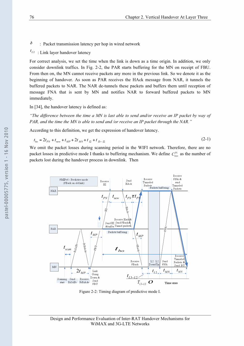
76 Chapter 2. Vertical Handover At Layer Three
Design and Performance Evaluation of Inter-RAT Handover Mechanisms for WiMAX and 3G-LTE Networks
: Packet transmission latency per hop in wired network
: Link layer handover latency
For correct analysis, we set the time when the link is down as a time origin. In addition, we only consider downlink traffics. In Fig. 2-2, the PAR starts buffering for the MN on receipt of FBU. From then on, the MN cannot receive packets any more in the previous link. So we denote it as the beginning of handover. As soon as PAR receives the HAck message from NAR, it tunnels the buffered packets to NAR. The NAR de-tunnels these packets and buffers them until reception of message FNA that is sent by MN and notifies NAR to forward buffered packets to MN immediately.
In [34], the handover latency is defined as:
“The difference between the time a MN is last able to send and/or receive an IP packet by way of PAR, and the time the MN is able to send and /or receive an IP packet through the NAR.”
According to this definition, we get the expression of handover latency.
(2-1)
We omit the packet losses during scanning period in the WIFI network. Therefore, there are no packet losses in predictive mode I thanks to buffering mechanism. We define as the number of packets lost during the handover process in downlink. Then
Figure 2-2: Timing diagram of predictive mode I.
past
el-0
0005
775,
ver
sion
1 -
16 N
ov 2
010
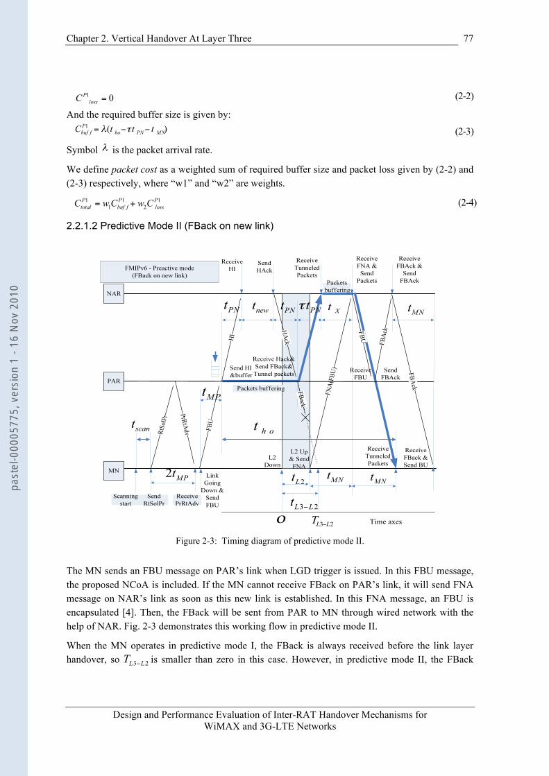
Chapter 2. Vertical Handover At Layer Three
Design and Performance Evaluation of Inter-RAT Handover Mechanisms for WiMAX and 3G-LTE Networks
77
(2-2)
And the required buffer size is given by:
(2-3)
Symbol is the packet arrival rate.
We define packet cost as a weighted sum of required buffer size and packet loss given by (2-2) and (2-3) respectively, where “w1” and “w2” are weights.
(2-4)
2.2.1.2 Predictive Mode II (FBack on new link)
Figure 2-3: Timing diagram of predictive mode II.
The MN sends an FBU message on PAR’s link when LGD trigger is issued. In this FBU message, the proposed NCoA is included. If the MN cannot receive FBack on PAR’s link, it will send FNA message on NAR’s link as soon as this new link is established. In this FNA message, an FBU is encapsulated [4]. Then, the FBack will be sent from PAR to MN through wired network with the help of NAR. Fig. 2-3 demonstrates this working flow in predictive mode II.
When the MN operates in predictive mode I, the FBack is always received before the link layer handover, so is smaller than zero in this case. However, in predictive mode II, the FBack
past
el-0
0005
775,
ver
sion
1 -
16 N
ov 2
010
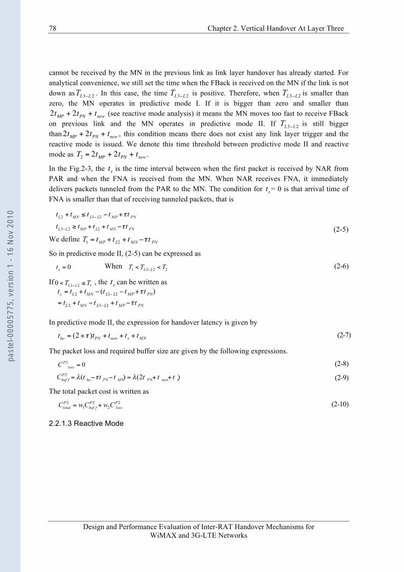
78 Chapter 2. Vertical Handover At Layer Three
Design and Performance Evaluation of Inter-RAT Handover Mechanisms for WiMAX and 3G-LTE Networks
cannot be received by the MN in the previous link as link layer handover has already started. For analytical convenience, we still set the time when the FBack is received on the MN if the link is not down as . In this case, the time is positive. Therefore, when is smaller than zero, the MN operates in predictive mode I. If it is bigger than zero and smaller than
€
2tMP + 2tPN + tnew (see reactive mode analysis) it means the MN moves too fast to receive FBack on previous link and the MN operates in predictive mode II. If is still bigger than
€
2tMP + 2tPN + tnew , this condition means there does not exist any link layer trigger and the reactive mode is issued. We denote this time threshold between predictive mode II and reactive mode as
€
T2 = 2tMP + 2tPN + tnew .
In the Fig.2-3, the
€
tx is the time interval between when the first packet is received by NAR from PAR and when the FNA is received from the MN. When NAR receives FNA, it immediately delivers packets tunneled from the PAR to the MN. The condition for
€
tx= 0 is that arrival time of FNA is smaller than that of receiving tunneled packets, that is
(2-5) We define
So in predictive mode II, (2-5) can be expressed as
When (2-6)
If , the can be written as
In predictive mode II, the expression for handover latency is given by
(2-7)
The packet loss and required buffer size are given by the following expressions.
(2-8)
(2-9)
The total packet cost is written as
(2-10)
2.2.1.3 Reactive Mode
past
el-0
0005
775,
ver
sion
1 -
16 N
ov 2
010
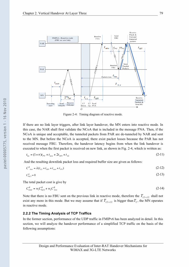
Chapter 2. Vertical Handover At Layer Three
Design and Performance Evaluation of Inter-RAT Handover Mechanisms for WiMAX and 3G-LTE Networks
79
Figure 2-4: Timing diagram of reactive mode.
If there are no link layer triggers, after link layer handover, the MN enters into reactive mode. In this case, the NAR shall first validate the NCoA that is included in the message FNA. Then, if the NCoA is unique and acceptable, the tunneled packets from PAR are de-tunneled by NAR and sent to the MN. But before the NCoA is accepted, there exist packet losses because the PAR has not received message FBU. Therefore, the handover latency begins from when the link handover is executed to when the first packet is received on new link, as shown in Fig. 2-4, which is written as:
(2-11)
And the resulting downlink packet loss and required buffer size are given as follows:
(2-12)
(2-13)
The total packet cost is give by
(2-14)
Note that there is no FBU sent on the previous link in reactive mode, therefore the shall not exist any more in this mode. But we may assume that if is bigger than , the MN operates in reactive mode.
2.2.2 The Timing Analysis of TCP Traffics In the former section, performance of the UDP traffic in FMIPv6 has been analyzed in detail. In this section, we will analyze the handover performance of a simplified TCP traffic on the basis of the following assumptions:
past
el-0
0005
775,
ver
sion
1 -
16 N
ov 2
010
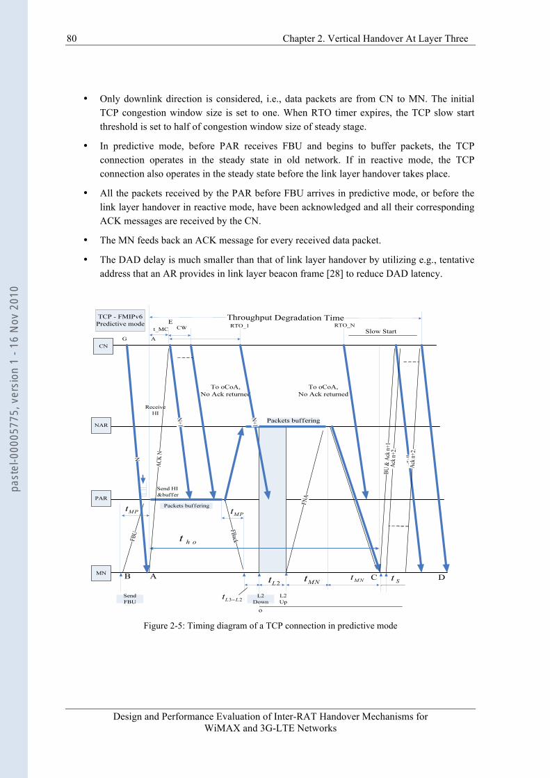
80 Chapter 2. Vertical Handover At Layer Three
Design and Performance Evaluation of Inter-RAT Handover Mechanisms for WiMAX and 3G-LTE Networks
• Only downlink direction is considered, i.e., data packets are from CN to MN. The initial TCP congestion window size is set to one. When RTO timer expires, the TCP slow start threshold is set to half of congestion window size of steady stage.
• In predictive mode, before PAR receives FBU and begins to buffer packets, the TCP connection operates in the steady state in old network. If in reactive mode, the TCP connection also operates in the steady state before the link layer handover takes place.
• All the packets received by the PAR before FBU arrives in predictive mode, or before the link layer handover in reactive mode, have been acknowledged and all their corresponding ACK messages are received by the CN.
• The MN feeds back an ACK message for every received data packet.
• The DAD delay is much smaller than that of link layer handover by utilizing e.g., tentative address that an AR provides in link layer beacon frame [28] to reduce DAD latency.
Figure 2-5: Timing diagram of a TCP connection in predictive mode
past
el-0
0005
775,
ver
sion
1 -
16 N
ov 2
010
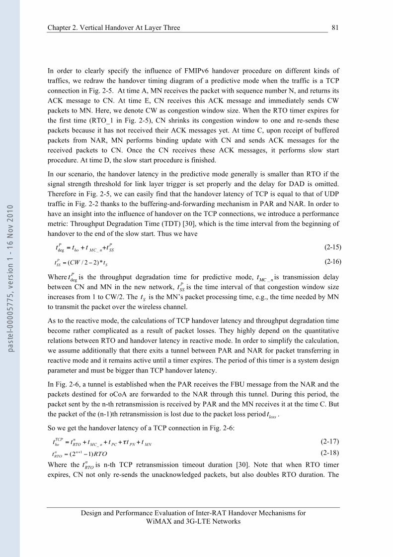
Chapter 2. Vertical Handover At Layer Three
Design and Performance Evaluation of Inter-RAT Handover Mechanisms for WiMAX and 3G-LTE Networks
81
In order to clearly specify the influence of FMIPv6 handover procedure on different kinds of traffics, we redraw the handover timing diagram of a predictive mode when the traffic is a TCP connection in Fig. 2-5. At time A, MN receives the packet with sequence number N, and returns its ACK message to CN. At time E, CN receives this ACK message and immediately sends CW packets to MN. Here, we denote CW as congestion window size. When the RTO timer expires for the first time (RTO_1 in Fig. 2-5), CN shrinks its congestion window to one and re-sends these packets because it has not received their ACK messages yet. At time C, upon receipt of buffered packets from NAR, MN performs binding update with CN and sends ACK messages for the received packets to CN. Once the CN receives these ACK messages, it performs slow start procedure. At time D, the slow start procedure is finished.
In our scenario, the handover latency in the predictive mode generally is smaller than RTO if the signal strength threshold for link layer trigger is set properly and the delay for DAD is omitted. Therefore in Fig. 2-5, we can easily find that the handover latency of TCP is equal to that of UDP traffic in Fig. 2-2 thanks to the buffering-and-forwarding mechanism in PAR and NAR. In order to have an insight into the influence of handover on the TCP connections, we introduce a performance metric: Throughput Degradation Time (TDT) [30], which is the time interval from the beginning of handover to the end of the slow start. Thus we have
(2-15)
(2-16)
Where is the throughput degradation time for predictive mode,
€
tMC _ n is transmission delay between CN and MN in the new network, is the time interval of that congestion window size increases from 1 to CW/2. The is the MN’s packet processing time, e.g., the time needed by MN to transmit the packet over the wireless channel.
As to the reactive mode, the calculations of TCP handover latency and throughput degradation time become rather complicated as a result of packet losses. They highly depend on the quantitative relations between RTO and handover latency in reactive mode. In order to simplify the calculation, we assume additionally that there exits a tunnel between PAR and NAR for packet transferring in reactive mode and it remains active until a timer expires. The period of this timer is a system design parameter and must be bigger than TCP handover latency.
In Fig. 2-6, a tunnel is established when the PAR receives the FBU message from the NAR and the packets destined for oCoA are forwarded to the NAR through this tunnel. During this period, the packet sent by the n-th retransmission is received by PAR and the MN receives it at the time C. But the packet of the (n-1)th retransmission is lost due to the packet loss period .
So we get the handover latency of a TCP connection in Fig. 2-6:
(2-17) (2-18)
Where the is n-th TCP retransmission timeout duration [30]. Note that when RTO timer expires, CN not only re-sends the unacknowledged packets, but also doubles RTO duration. The
past
el-0
0005
775,
ver
sion
1 -
16 N
ov 2
010
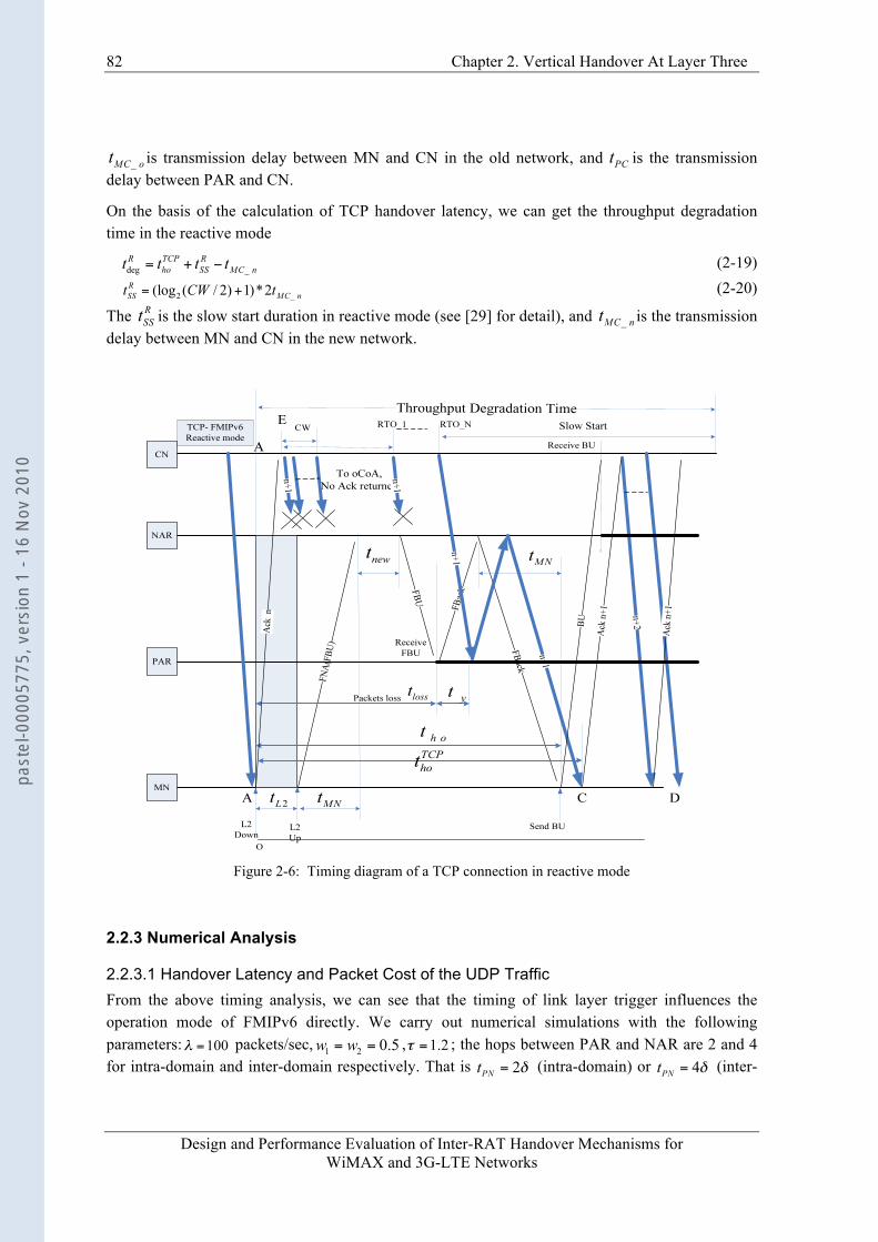
82 Chapter 2. Vertical Handover At Layer Three
Design and Performance Evaluation of Inter-RAT Handover Mechanisms for WiMAX and 3G-LTE Networks
is transmission delay between MN and CN in the old network, and is the transmission delay between PAR and CN.
On the basis of the calculation of TCP handover latency, we can get the throughput degradation time in the reactive mode
(2-19) (2-20)
The is the slow start duration in reactive mode (see [29] for detail), and is the transmission delay between MN and CN in the new network.
Figure 2-6: Timing diagram of a TCP connection in reactive mode
2.2.3 Numerical Analysis
2.2.3.1 Handover Latency and Packet Cost of the UDP Traffic From the above timing analysis, we can see that the timing of link layer trigger influences the operation mode of FMIPv6 directly. We carry out numerical simulations with the following parameters: packets/sec, , ; the hops between PAR and NAR are 2 and 4 for intra-domain and inter-domain respectively. That is (intra-domain) or (inter-
past
el-0
0005
775,
ver
sion
1 -
16 N
ov 2
010
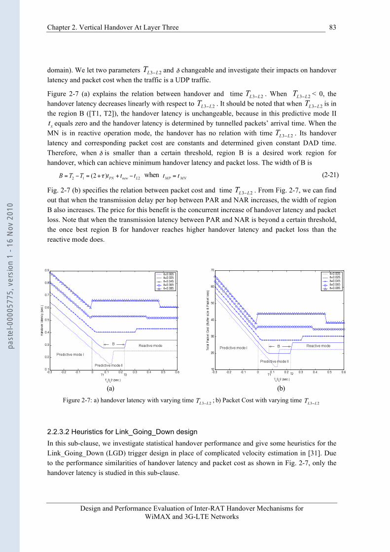
Chapter 2. Vertical Handover At Layer Three
Design and Performance Evaluation of Inter-RAT Handover Mechanisms for WiMAX and 3G-LTE Networks
83
domain). We let two parameters and changeable and investigate their impacts on handover latency and packet cost when the traffic is a UDP traffic.
Figure 2-7 (a) explains the relation between handover and time . When < 0, the handover latency decreases linearly with respect to . It should be noted that when is in the region B ([T1, T2]), the handover latency is unchangeable, because in this predictive mode II
equals zero and the handover latency is determined by tunnelled packets’ arrival time. When the MN is in reactive operation mode, the handover has no relation with time . Its handover latency and corresponding packet cost are constants and determined given constant DAD time. Therefore, when is smaller than a certain threshold, region B is a desired work region for handover, which can achieve minimum handover latency and packet loss. The width of B is
when (2-21)
Fig. 2-7 (b) specifies the relation between packet cost and time . From Fig. 2-7, we can find out that when the transmission delay per hop between PAR and NAR increases, the width of region B also increases. The price for this benefit is the concurrent increase of handover latency and packet loss. Note that when the transmission latency between PAR and NAR is beyond a certain threshold, the once best region B for handover reaches higher handover latency and packet loss than the reactive mode does.
(a) (b)
Figure 2-7: a) handover latency with varying time ; b) Packet Cost with varying time
2.2.3.2 Heuristics for Link_Going_Down design In this sub-clause, we investigate statistical handover performance and give some heuristics for the Link_Going_Down (LGD) trigger design in place of complicated velocity estimation in [31]. Due to the performance similarities of handover latency and packet cost as shown in Fig. 2-7, only the handover latency is studied in this sub-clause.
past
el-0
0005
775,
ver
sion
1 -
16 N
ov 2
010
84 Chapter 2. Vertical Handover At Layer Three
Design and Performance Evaluation of Inter-RAT Handover Mechanisms for WiMAX and 3G-LTE Networks
On the LGD trigger, a MN exchanges messages with the network (PAR) to make it prepare for the incoming link and IP handover. On the Link_Down (LD) trigger, the MN performs real link layer handover and cannot receive and send any packets. In predictive mode, since LGD trigger reflects the signal quality degradation trend in advance, any signal threshold gap between LGD trigger and LD trigger will cause inaccurate signal quality prediction because of signal fluctuation or noise. Intuitively, the larger this threshold gap, the lower LD possibility would be given LGD. One extreme case is: when this gap reaches infinity, the LD possibility shall reach zero given LGD. In reactive mode, LGD trigger is totally ignored because it does not exist or is overdue.
This threshold gap is equivalent to time interval between LGD and LD triggers’ issue time. Let X be the random variable for the time interval between LGD and LD triggering time. To simplify analysis, we only consider the case where after LGD, the LD is certain to happen sooner or later 5. Hence, once a LD happens, the possibility of interval X with a small value is much higher than that with a large value. Generally, in predictive mode, the probability density function for the X is usually unknown because it depends on physical layer scheme or trigger threshold type (SNR or RSSI) or MN mobility pattern or channel condition (fast or slow fading). In [84], the interval X is assumed to be exponentially distributed:
€
fX (x) =ηe−ηx,x ≥ 0 (2-22)
Denote LGD triggering time as time origin. Then
€
x indicates the time when LD trigger is issued. The much larger the
€
η, the more rapidly
€
fX (x) decreases. However, decreasing factor
€
η, which may reflect physical channel conditions or MN mobility patterns, is totally unknown. We describe in Fig. 2-8 the timing relations between LGD/LD triggers and operation modes when LGD is issued.
Figure 2-8: Timing relation when LGD is issued
So, the average handover latency of predictive mode can be written as below.
(2-23)
5 Note that there is possible that LGD would never result in LD, which is omitted in this sub-clause.
€
thoP = fX0
T2−T1∫ (t) * tho1 dt + fXT2−T1
∞
∫ (t) * tho2 dt
past
el-0
0005
775,
ver
sion
1 -
16 N
ov 2
010
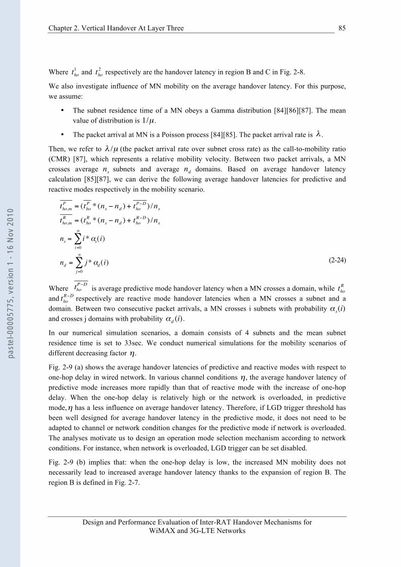
Chapter 2. Vertical Handover At Layer Three
Design and Performance Evaluation of Inter-RAT Handover Mechanisms for WiMAX and 3G-LTE Networks
85
Where
€
tho1 and
€
tho2 respectively are the handover latency in region B and C in Fig. 2-8.
We also investigate influence of MN mobility on the average handover latency. For this purpose, we assume:
• The subnet residence time of a MN obeys a Gamma distribution [84][86][87]. The mean value of distribution is
€
1/µ .
• The packet arrival at MN is a Poisson process [84][85]. The packet arrival rate is
€
λ .
Then, we refer to
€
λ /µ (the packet arrival rate over subnet cross rate) as the call-to-mobility ratio (CMR) [87], which represents a relative mobility velocity. Between two packet arrivals, a MN crosses average
€
ns subnets and average
€
nd domains. Based on average handover latency calculation [85][87], we can derive the following average handover latencies for predictive and reactive modes respectively in the mobility scenario.
(2-24)
Where is average predictive mode handover latency when a MN crosses a domain, while
€
thoR
and
€
thoR−D respectively are reactive mode handover latencies when a MN crosses a subnet and a
domain. Between two consecutive packet arrivals, a MN crosses i subnets with probability
€
α s(i) and crosses j domains with probability
€
αd (i).
In our numerical simulation scenarios, a domain consists of 4 subnets and the mean subnet residence time is set to 33sec. We conduct numerical simulations for the mobility scenarios of different decreasing factor
€
η.
Fig. 2-9 (a) shows the average handover latencies of predictive and reactive modes with respect to one-hop delay in wired network. In various channel conditions
€
η, the average handover latency of predictive mode increases more rapidly than that of reactive mode with the increase of one-hop delay. When the one-hop delay is relatively high or the network is overloaded, in predictive mode,
€
η has a less influence on average handover latency. Therefore, if LGD trigger threshold has been well designed for average handover latency in the predictive mode, it does not need to be adapted to channel or network condition changes for the predictive mode if network is overloaded. The analyses motivate us to design an operation mode selection mechanism according to network conditions. For instance, when network is overloaded, LGD trigger can be set disabled.
Fig. 2-9 (b) implies that: when the one-hop delay is low, the increased MN mobility does not necessarily lead to increased average handover latency thanks to the expansion of region B. The region B is defined in Fig. 2-7.
€
tho,mP = (tho
P * (ns − nd ) + thoP−D ) /ns
tho,mR = (tho
R * (ns − nd ) + thoR−D ) /ns
€
thoP−D
€
ns = i*αs(i)i=0
∞
∑
nd = j*αd (i)j=0
∞
∑
past
el-0
0005
775,
ver
sion
1 -
16 N
ov 2
010
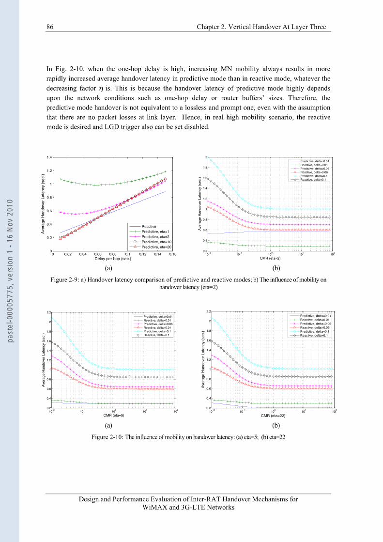
86 Chapter 2. Vertical Handover At Layer Three
Design and Performance Evaluation of Inter-RAT Handover Mechanisms for WiMAX and 3G-LTE Networks
In Fig. 2-10, when the one-hop delay is high, increasing MN mobility always results in more rapidly increased average handover latency in predictive mode than in reactive mode, whatever the decreasing factor
€
η is. This is because the handover latency of predictive mode highly depends upon the network conditions such as one-hop delay or router buffers’ sizes. Therefore, the predictive mode handover is not equivalent to a lossless and prompt one, even with the assumption that there are no packet losses at link layer. Hence, in real high mobility scenario, the reactive mode is desired and LGD trigger also can be set disabled.
0 0.02 0.04 0.06 0.08 0.1 0.12 0.14 0.160
0.2
0.4
0.6
0.8
1
1.2
1.4
Delay per hop (sec.)
Aver
age
Hand
over
Lat
ency
(sec
.)
ReactivePredictive, eta=1Predictive, eta=2Predictive, eta=10Predictive, eta=20
10 2 10 1 100 101 1020.2
0.4
0.6
0.8
1
1.2
1.4
1.6
1.8
2
CMR (eta=2)
Aver
age
Han
dove
r Lat
ency
(sec
.)
Predictive, delta=0.01Reactive, delta=0.01Predictive, delta=0.06Reactive, delta=0.06Predictive, delta=0.1Reactive, delta=0.1
(a) (b)
Figure 2-9: a) Handover latency comparison of predictive and reactive modes; b) The influence of mobility on handover latency (eta=2)
10 2 10 1 100 101 1020.2
0.4
0.6
0.8
1
1.2
1.4
1.6
1.8
2
2.2
CMR (eta=5)
Aver
age
Han
dove
r Lat
ency
(sec
.)
Predictive, delta=0.01Reactive, delta=0.01Predictive, delta=0.06Reactive, delta=0.01Predictive, delta=0.1Reactive, delta=0.1
10 2 10 1 100 101 1020.2
0.4
0.6
0.8
1
1.2
1.4
1.6
1.8
2
2.2
CMR (eta=22)
Aver
age
Han
dove
r Lat
ency
(sec
.)
Predictive, delta=0.01Reactive, delta=0.01Predictive, delta=0.06Reactive, delta=0.06Predictive, delta=0.1Reactive, delta=0.1
(a) (b)
Figure 2-10: The influence of mobility on handover latency: (a) eta=5; (b) eta=22
past
el-0
0005
775,
ver
sion
1 -
16 N
ov 2
010
Chapter 2. Vertical Handover At Layer Three
Design and Performance Evaluation of Inter-RAT Handover Mechanisms for WiMAX and 3G-LTE Networks
87
Based on Fig. 2-7, Fig.2-9 and Fig. 2-10, we obtain the following heuristics for the LGD trigger design:
• When the network is lightly loaded, setting LGD trigger threshold near to LD trigger threshold generally can achieve better handover performance.
• When the network is overloaded, the LGD trigger threshold needs not to be deliberately adjusted for the predictive mode.
• When the network is overloaded, the LGD trigger can be set disabled in order to make the network operate in reactive mode, in which the shorter handover latency would be achieved.
• When the MN is in high mobility, the reactive mode is preferred.
2.2.3.3 Discussion Based on the above analyses, we draw the following conclusions:
• When transmission delay between PAR and NAR is below a certain threshold, in order to achieve the best handover performance, MN does not necessarily receive the FBU message on the previous link 6.
• When the FMIPv6 operates in predictive mode, the handover performance highly depends on the proper design of trigger threshold. An improper design of trigger threshold may not only reduce the handover target certainty, but also increase handover latency. Although [31] proposes a QoS assuring trigger design method to calculate anticipation time before handover, the complicated velocity estimation of the MN is needed.
• Link layer trigger design, such as LGD trigger, highly depends on both the physical layer situation (e.g., mobility pattern, channel conditions) and wired network conditions (e.g., transmission delay, hop number).
• Although FMIPv6 can achieve shorter handover latency than MIPv6, the handover latency of link layer still is the lower bound of FMIPv6 handover latency.
• The handover latency of reactive mode is always longer than the shortest one of predictive mode (see Fig. 2-7 (a)). However, reactive mode handover latency is independent of link layer triggering time, and can be predicted given network parameters such as transmission delay and DAD time (see (2-11)).
• This kind of mobile-controlled handover of FMIPv6 actually is called cell selection/reselection in terms of 3GPP standards such as UMTS. In GERAN or UMTS, the PS (Packet Switch) handover procedure is controlled by the network. This kind of network-controlled handover approach can provide better handover performance in terms of packet loss and handover latency.
6 This conclusion is similar to the one in [26].
past
el-0
0005
775,
ver
sion
1 -
16 N
ov 2
010
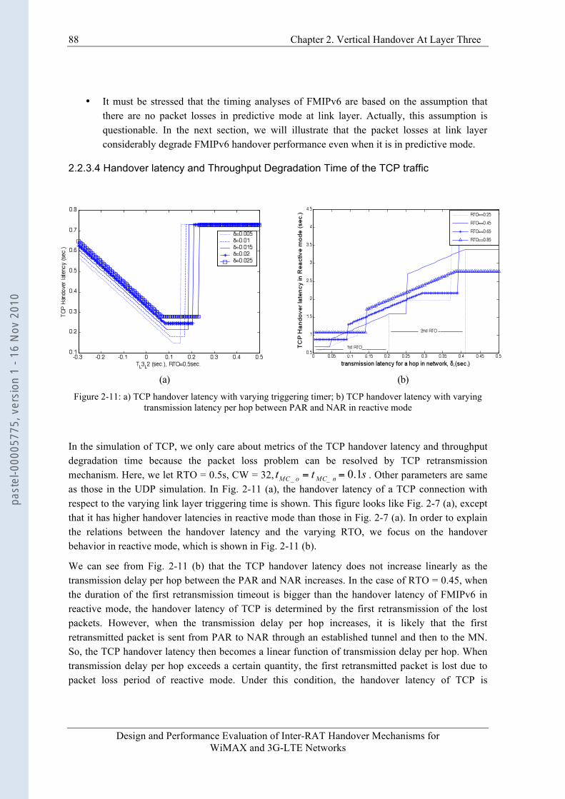
88 Chapter 2. Vertical Handover At Layer Three
Design and Performance Evaluation of Inter-RAT Handover Mechanisms for WiMAX and 3G-LTE Networks
• It must be stressed that the timing analyses of FMIPv6 are based on the assumption that there are no packet losses in predictive mode at link layer. Actually, this assumption is questionable. In the next section, we will illustrate that the packet losses at link layer considerably degrade FMIPv6 handover performance even when it is in predictive mode.
2.2.3.4 Handover latency and Throughput Degradation Time of the TCP traffic
(a) (b)
Figure 2-11: a) TCP handover latency with varying triggering timer; b) TCP handover latency with varying transmission latency per hop between PAR and NAR in reactive mode
In the simulation of TCP, we only care about metrics of the TCP handover latency and throughput degradation time because the packet loss problem can be resolved by TCP retransmission mechanism. Here, we let RTO = 0.5s, CW = 32, . Other parameters are same as those in the UDP simulation. In Fig. 2-11 (a), the handover latency of a TCP connection with respect to the varying link layer triggering time is shown. This figure looks like Fig. 2-7 (a), except that it has higher handover latencies in reactive mode than those in Fig. 2-7 (a). In order to explain the relations between the handover latency and the varying RTO, we focus on the handover behavior in reactive mode, which is shown in Fig. 2-11 (b).
We can see from Fig. 2-11 (b) that the TCP handover latency does not increase linearly as the transmission delay per hop between the PAR and NAR increases. In the case of RTO = 0.45, when the duration of the first retransmission timeout is bigger than the handover latency of FMIPv6 in reactive mode, the handover latency of TCP is determined by the first retransmission of the lost packets. However, when the transmission delay per hop increases, it is likely that the first retransmitted packet is sent from PAR to NAR through an established tunnel and then to the MN. So, the TCP handover latency then becomes a linear function of transmission delay per hop. When transmission delay per hop exceeds a certain quantity, the first retransmitted packet is lost due to packet loss period of reactive mode. Under this condition, the handover latency of TCP is
past
el-0
0005
775,
ver
sion
1 -
16 N
ov 2
010
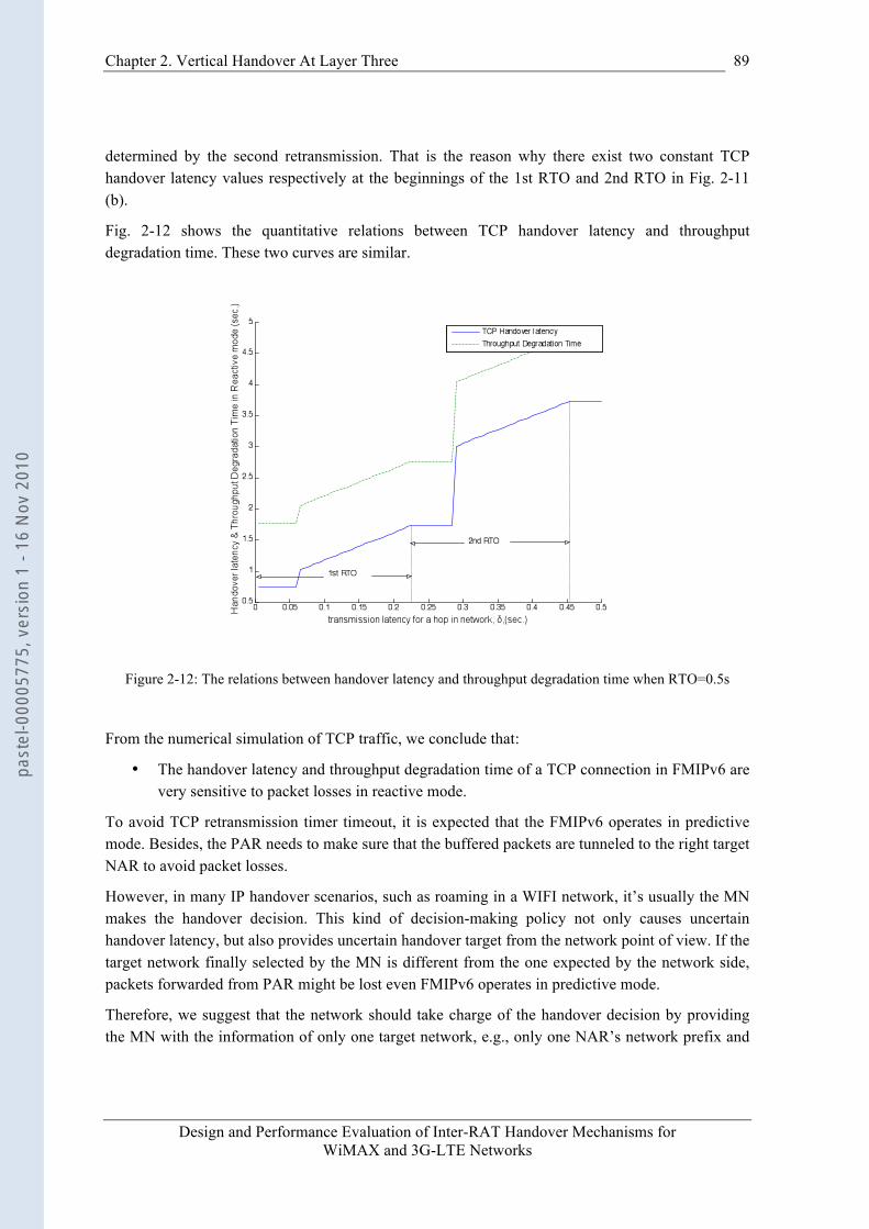
Chapter 2. Vertical Handover At Layer Three
Design and Performance Evaluation of Inter-RAT Handover Mechanisms for WiMAX and 3G-LTE Networks
89
determined by the second retransmission. That is the reason why there exist two constant TCP handover latency values respectively at the beginnings of the 1st RTO and 2nd RTO in Fig. 2-11 (b).
Fig. 2-12 shows the quantitative relations between TCP handover latency and throughput degradation time. These two curves are similar.
Figure 2-12: The relations between handover latency and throughput degradation time when RTO=0.5s
From the numerical simulation of TCP traffic, we conclude that:
• The handover latency and throughput degradation time of a TCP connection in FMIPv6 are very sensitive to packet losses in reactive mode.
To avoid TCP retransmission timer timeout, it is expected that the FMIPv6 operates in predictive mode. Besides, the PAR needs to make sure that the buffered packets are tunneled to the right target NAR to avoid packet losses.
However, in many IP handover scenarios, such as roaming in a WIFI network, it’s usually the MN makes the handover decision. This kind of decision-making policy not only causes uncertain handover latency, but also provides uncertain handover target from the network point of view. If the target network finally selected by the MN is different from the one expected by the network side, packets forwarded from PAR might be lost even FMIPv6 operates in predictive mode.
Therefore, we suggest that the network should take charge of the handover decision by providing the MN with the information of only one target network, e.g., only one NAR’s network prefix and
past
el-0
0005
775,
ver
sion
1 -
16 N
ov 2
010
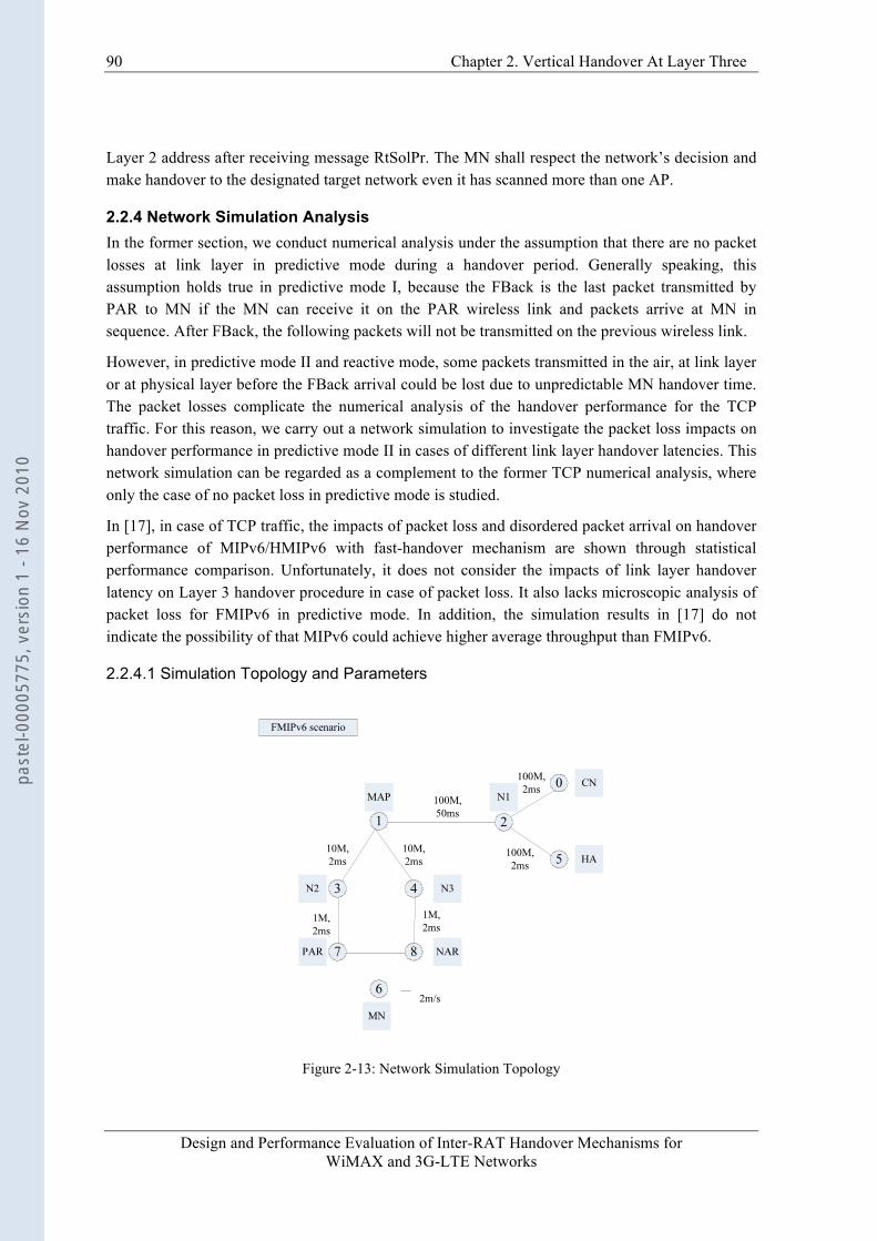
90 Chapter 2. Vertical Handover At Layer Three
Design and Performance Evaluation of Inter-RAT Handover Mechanisms for WiMAX and 3G-LTE Networks
Layer 2 address after receiving message RtSolPr. The MN shall respect the network’s decision and make handover to the designated target network even it has scanned more than one AP.
2.2.4 Network Simulation Analysis In the former section, we conduct numerical analysis under the assumption that there are no packet losses at link layer in predictive mode during a handover period. Generally speaking, this assumption holds true in predictive mode I, because the FBack is the last packet transmitted by PAR to MN if the MN can receive it on the PAR wireless link and packets arrive at MN in sequence. After FBack, the following packets will not be transmitted on the previous wireless link.
However, in predictive mode II and reactive mode, some packets transmitted in the air, at link layer or at physical layer before the FBack arrival could be lost due to unpredictable MN handover time. The packet losses complicate the numerical analysis of the handover performance for the TCP traffic. For this reason, we carry out a network simulation to investigate the packet loss impacts on handover performance in predictive mode II in cases of different link layer handover latencies. This network simulation can be regarded as a complement to the former TCP numerical analysis, where only the case of no packet loss in predictive mode is studied.
In [17], in case of TCP traffic, the impacts of packet loss and disordered packet arrival on handover performance of MIPv6/HMIPv6 with fast-handover mechanism are shown through statistical performance comparison. Unfortunately, it does not consider the impacts of link layer handover latency on Layer 3 handover procedure in case of packet loss. It also lacks microscopic analysis of packet loss for FMIPv6 in predictive mode. In addition, the simulation results in [17] do not indicate the possibility of that MIPv6 could achieve higher average throughput than FMIPv6.
2.2.4.1 Simulation Topology and Parameters
Figure 2-13: Network Simulation Topology
past
el-0
0005
775,
ver
sion
1 -
16 N
ov 2
010
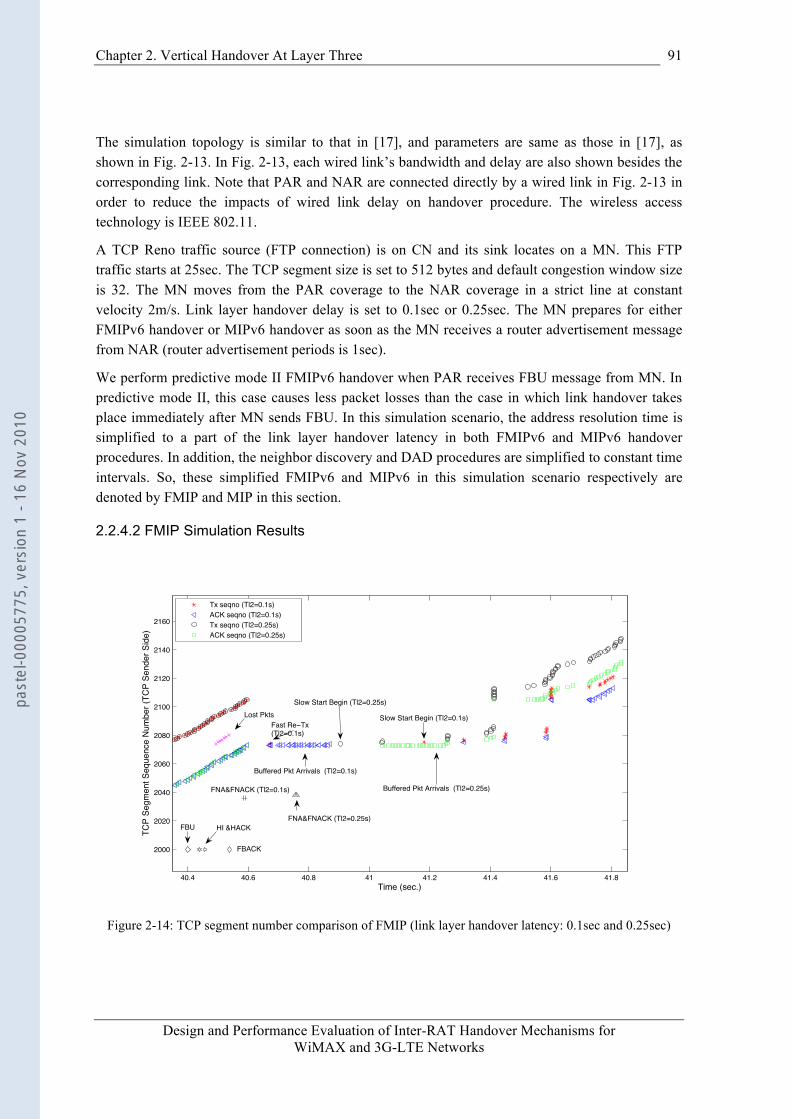
Chapter 2. Vertical Handover At Layer Three
Design and Performance Evaluation of Inter-RAT Handover Mechanisms for WiMAX and 3G-LTE Networks
91
The simulation topology is similar to that in [17], and parameters are same as those in [17], as shown in Fig. 2-13. In Fig. 2-13, each wired link’s bandwidth and delay are also shown besides the corresponding link. Note that PAR and NAR are connected directly by a wired link in Fig. 2-13 in order to reduce the impacts of wired link delay on handover procedure. The wireless access technology is IEEE 802.11.
A TCP Reno traffic source (FTP connection) is on CN and its sink locates on a MN. This FTP traffic starts at 25sec. The TCP segment size is set to 512 bytes and default congestion window size is 32. The MN moves from the PAR coverage to the NAR coverage in a strict line at constant velocity 2m/s. Link layer handover delay is set to 0.1sec or 0.25sec. The MN prepares for either FMIPv6 handover or MIPv6 handover as soon as the MN receives a router advertisement message from NAR (router advertisement periods is 1sec).
We perform predictive mode II FMIPv6 handover when PAR receives FBU message from MN. In predictive mode II, this case causes less packet losses than the case in which link handover takes place immediately after MN sends FBU. In this simulation scenario, the address resolution time is simplified to a part of the link layer handover latency in both FMIPv6 and MIPv6 handover procedures. In addition, the neighbor discovery and DAD procedures are simplified to constant time intervals. So, these simplified FMIPv6 and MIPv6 in this simulation scenario respectively are denoted by FMIP and MIP in this section.
2.2.4.2 FMIP Simulation Results
40.4 40.6 40.8 41 41.2 41.4 41.6 41.8
2000
2020
2040
2060
2080
2100
2120
2140
2160
Time (sec.)
TCP
Segm
ent S
eque
nce
Num
ber (
TCP
Send
er S
ide)
Tx seqno (Tl2=0.1s)ACK seqno (Tl2=0.1s)Tx seqno (Tl2=0.25s)ACK seqno (Tl2=0.25s)
Slow Start Begin (Tl2=0.25s)
HI &HACKFBU
FNA&FNACK (Tl2=0.1s)
FBACK
Slow Start Begin (Tl2=0.1s)
Buffered Pkt Arrivals (Tl2=0.1s)
Buffered Pkt Arrivals (Tl2=0.25s)
FNA&FNACK (Tl2=0.25s)
Lost PktsFast Re Tx(Tl2=0.1s)
Figure 2-14: TCP segment number comparison of FMIP (link layer handover latency: 0.1sec and 0.25sec)
past
el-0
0005
775,
ver
sion
1 -
16 N
ov 2
010
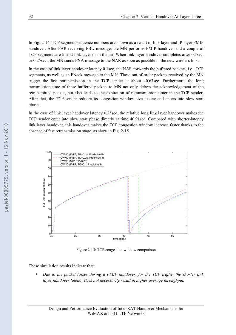
92 Chapter 2. Vertical Handover At Layer Three
Design and Performance Evaluation of Inter-RAT Handover Mechanisms for WiMAX and 3G-LTE Networks
In Fig. 2-14, TCP segment sequence numbers are shown as a result of link layer and IP layer FMIP handover. After PAR receiving FBU message, the MN performs FMIP handover and a couple of TCP segments are lost at link layer or in the air. When link layer handover completes after 0.1sec. or 0.25sec., the MN sends FNA message to the NAR as soon as possible in the new wireless link.
In the case of link layer handover latency 0.1sec, the NAR forwards the buffered packets, i.e., TCP segments, as well as an FNack message to the MN. These out-of-order packets received by the MN trigger the fast retransmission in the TCP sender at about 40.67sec. Furthermore, the long transmission time of these buffered packets to MN not only delays the acknowledgement of the retransmitted packet, but also leads to the expiration of retransmission timer in the TCP sender. After that, the TCP sender reduces its congestion window size to one and enters into slow start phase.
In the case of link layer handover latency 0.25sec, the relative long link layer handover makes the TCP sender enter into slow start phase directly at time 40.91sec. Compared with shorter-latency link layer handover, this handover makes the TCP congestion window increase faster thanks to the absence of fast retransmission stage, as show in Fig. 2-15.
25 30 35 40 45 500
10
20
30
40
50
60
70
80
90
100
Time (sec.)
TCP
Cong
estio
n W
indo
w
CWND (FMIP, Tl2=0.1s, Predictive II)CWND (FMIP, Tl2=0.25, Predictive II)CWND (MIP, Tl2=0.25)CWND (FMIP, Tl2=0.1, Predictive I)
Figure 2-15: TCP congestion window comparison
These simulation results indicate that:
• Due to the packet losses during a FMIP handover, for the TCP traffic, the shorter link layer handover latency does not necessarily result in higher average throughput.
past
el-0
0005
775,
ver
sion
1 -
16 N
ov 2
010

Chapter 2. Vertical Handover At Layer Three
Design and Performance Evaluation of Inter-RAT Handover Mechanisms for WiMAX and 3G-LTE Networks
93
This counterintuitive conclusion is different from our former discussions in sub-clause 2.2.3.3 because these discussions are based on the no-packet-loss assumption in predictive mode.
2.2.4.3 FMIP and MIP Simulation Result Comparison We also carry out MIP simulation in the same network scenario and its TCP segment sequence number variation is shown in Fig. 2-16. Although link layer handover execution time for MIP and FMIP is different (0.1sec for FMIP and 0.25sec for MIP), the observation of respective TCP segment sequence number variation is sufficient for performance comparison.
In MIP, the longer link layer handover latency and address resolution latency make the TCP sender enter into slow start phase directly. Compared with FMIP in predictive mode II with link layer handover latency 0.1sec, the MIP makes TCP congestion window increase much faster due to the absence of fast retransmission stage. In MIP, the lost packets or segments during the link layer handover procedure and address resolution phase do not delay the TCP acknowledgement of a retransmitted segment.
40.5 41 41.5 42 42.5 43 43.5 44 44.5
1900
2000
2100
2200
2300
2400TX Seqno (FMIP, Tl2=0.1s)ACK Seqno (FMIP, Tl2=0.1s)TX Seqno (MIP, Tl2=0.25s)ACK Seqno (FMIP, Tl2=0.25s)
Fast Retransmit (FMIP)
Re Tx Timeout (FMIP)Slow Start
Re Tx Timeout (MIP)Slow Start
Figure 2-16: TCP segment number comparison between FMIP (link layer handover 0.1sec) and MIP (link
layer handover 0.25sec)
Therefore, we draw the following important conclusion:
• The buffering-and-forwarding context transfer scheme of FMIPv6 does not necessarily bring better handover performance.
past
el-0
0005
775,
ver
sion
1 -
16 N
ov 2
010
94 Chapter 2. Vertical Handover At Layer Three
Design and Performance Evaluation of Inter-RAT Handover Mechanisms for WiMAX and 3G-LTE Networks
We will re-see this conclusion in a latter chapter. On the other side, the buffering-and-forwarding is a well-accepted context transfer scheme at IP layer because: firstly, its implementation is quite simple; secondly, no modification is needed to IP protocol stacks on the MN side. Unfortunately, applying simple buffer-and-forwarding context transfer at IP layer cannot bring a lossless handover.
In short, when packet loss happens at lower layers, FMIPv6 does not necessarily provide satisfactory handover performance due to its inefficient context transfer scheme. Therefore, another more effective context transfer scheme or a better lossless handover at lower layers are demanded for the smooth and seamless roaming. Realizing a lossless handover at lower layers generally requires modifications to both network and MN protocol stacks. We will present our lossless handover proposal in the next chapter.
2.2.5 Hybrid Operation Mode
2.2.5.1 Working Principle Generally, if there are no packet losses in predictive mode, FMIPv6 can achieve better handover performance than MIPv6, but its handover performance uncertainty is undesirable to:
• Real-time traffics such as VoIP. This kind of traffic often requires stringent handover delay, e.g., 40ms [32];
• Stringent handover latency scenario, e.g., 200ms in 802.20 [33].
In order to ensure handover latency, we propose a hybrid operation mode scheme that utilizes the certainty of reactive mode on handover latency to satisfy these stringent latency demands. Before introducing the proposed scheme, we make the following assumptions:
• The DAD delay is much smaller than link layer handover latency by using tentative address [28]. The tentative address refers to the validated IP address used before a handover. An AR provides tentative addresses in link layer beacon frame [28] in order to reduce DAD latency significantly.
• The link layer handover latency can be considered as a system constant parameter from ARs’ point of view, e.g., 50ms in 3G.
Thus, when a predictive operation mode is triggered, the network calculates the prospective handover latency of reactive mode. If it is below a delay threshold, the network chooses reactive mode by not sending back FBack message to the MN and continuously transmits packets on PAR’s link. If not, the operation degrades to normal FMIPv6 one. The reason why it is the network that controls the mode selection rather than the MN is that: the network dynamic state information, such as transmission delay between ARs and the target network’s Round Trip Delay (RTD), is only available to ARs. The hybrid operation mode consists of three phases as follows:
• Measurements: The MN should periodically report RTD measurement to PAR in the message RtSolPr. The PAR receives the RTD measurement reports sent from many MNs and periodically averages them to get an estimation of dynamic network access time. In addition, the PAR should also periodically detect the transmission delay between itself and
past
el-0
0005
775,
ver
sion
1 -
16 N
ov 2
010
Chapter 2. Vertical Handover At Layer Three
Design and Performance Evaluation of Inter-RAT Handover Mechanisms for WiMAX and 3G-LTE Networks
95
other neighbor ARs. During the handover execution phase, the current RTD of NAR’s link should be sent back to PAR together with the verified NCoA in message Hack. The period for MN’s RTD reporting can be controlled by PAR through unsolicited message PrRtAdv if necessary.
• Criteria: When the PAR receives a FBU from a MN on its link, it carries out normal signaling exchanges with NAR. In Hack, the RTD of target network is indicated. Then the PAR checks the type of a traffic destined for the MN. If it is a real-time traffic, the PAR calculates the prospective handover delay of reactive mode based on the following expression:
(2-25)
If latency of (2-25) is smaller than a predefined threshold, e.g., 200ms, the proposed hybrid operation scheme is initiated. Otherwise, the PAR executes conventional FMIPv6 predictive operation. Note that in (2-25), there is no item for DAD delay, since DAD delay is much smaller than link layer handover latency by using pre-assigned tentative address. Therefore, in hybrid mode, the DAD delay can be omitted.
• Execution: If the hybrid mode is chosen, the PAR continuously transmits packets on its link without sending message FBack until it receives the message FBU from NAR. Hereafter, the packets destined for PCoA are forwarded to NAR through an established tunnel.
2.2.5.2 Numerical Simulation We carry out numerical simulations for 2000 times for one MN. The handover mode is determined by the value of which is uniformly distributed in the region [-0.3sec, 0.3sec]. The transmission delay per hop in wired network is variable, while other network parameters are fixed and take the same values as in the sections 2.2.3.1 and 2.2.3.4. If the handover latency is above a threshold of 200ms, the traffic or connection is considered as a failed call.
From Fig. 2-17 (a) we can find out the call drop rate of hybrid operation mode is much smaller than that of normal predictive mode under the condition that the transmission delay per hop is below 0.015sec. When the transmission delay for one hop goes beyond 0.015sec, the handover performance regresses to the normal FMIPv6 performance.
The hybrid mode has a delighted feature: slightly increasing DAD delay can reduce call drop rate. As a matter of fact, the DAD delay increase only influences the handover of predictive mode instead of hybrid mode (Certainly, DAD delay is assumed to be much smaller than link layer handover latency). So the MN has more chance to choose hybrid mode.
Additionally, by observing the curves of hybrid mode, we can see that call drop rate decreases linearly when transmission delay per hop is below 0.015sec. In Fig. 2-7 we have stated the region B expands with the transmission delay per hop increasing. So, when the transmission delay per hop increases, it is more likely that predictive mode is triggered initially and subsequently the hybrid mode is chosen given a fixed distribution region of .
past
el-0
0005
775,
ver
sion
1 -
16 N
ov 2
010
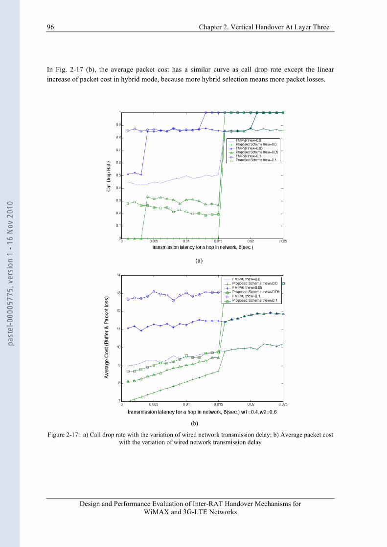
96 Chapter 2. Vertical Handover At Layer Three
Design and Performance Evaluation of Inter-RAT Handover Mechanisms for WiMAX and 3G-LTE Networks
In Fig. 2-17 (b), the average packet cost has a similar curve as call drop rate except the linear increase of packet cost in hybrid mode, because more hybrid selection means more packet losses.
(a)
(b)
Figure 2-17: a) Call drop rate with the variation of wired network transmission delay; b) Average packet cost with the variation of wired network transmission delay
past
el-0
0005
775,
ver
sion
1 -
16 N
ov 2
010

Chapter 2. Vertical Handover At Layer Three
Design and Performance Evaluation of Inter-RAT Handover Mechanisms for WiMAX and 3G-LTE Networks
97
2.2.6 Conclusion The FMIPv6 reduces the long handover latency of MIPv6 by fast movement detection and fast binding update. But it suffers from uncertain handover latency and target. We take advantage of the certainty of handover latency in reactive mode and pre-configuration of NCoA in predictive mode, to propose a hybrid mode for the real-time traffic that demands stringent handover latency instead of low packet losses. The numerical simulation results show that the hybrid mode can achieve lower call drop rate and lower packet cost when the wired network transmission delay is below a given threshold under the assumption that the DAD delay is much smaller than link handover latency. In the case of throughput-sensitive traffics such as FTP, it is desired that FMIPv6 operates in predictive mode with assuring handover target. In order to reduce uncertainty of handover target, we suggest it is the network (PAR) that makes the handover decision by providing the MN with target network information of only one NAR.
2.3 Conclusion This chapter is an investigation of state of art of mobility management in wireless IP networks. Because of weakness of conventional Mobile IP, such as long handover latency and high packet loss rate, IETF proposes various Mobile IP extensions. For example, the FMIPv6 reduces the handover latency and packet losses, while HMIPv6 reduces the signaling overhead in the IP core network. A variety of experiments and simulations show that, although these Mobile IP extensions achieve better performance than Mobile IP, some metrics are still not suitable for real-time traffics such as VoIP. Therefore, many modifications or optimizations are proposed to improve the handover performance of these Mobile IP extensions, e.g., adding multi-casting function to HMIPv6 during an inter-domain handover. Whether these enhancements of Mobile IP and its extensions can satisfy the handover performance requirements of the high-QoS-demanding traffic in real IP networks is still an open issue.
Since handover performance of MIPv6 usually is worse than that of FMIPv6 or FHMIPv6 (but not necessarily), we study the timing and operation mode of FMIPv6 to investigate IP layer handover performance bottleneck.
The FMIPv6 aims at reducing handover latency by fast movement detection and fast binding update. In addition, it also reduces packet losses by buffering packets prior to link layer handover. These optimizations are based on the introduction of link layer trigger, such as Link_Going_Down (LGD) trigger. However, if the signal strength or signal quality threshold for Link_Going_Down trigger is not set appropriately or the MN moves too slowly, the FMIPv6 may suffer from long handover latency. On the other hand, if the MN moves too fast, some signaling messages in predictive mode cannot be finished before link handover takes place. Then FMIPv6 operates in reactive mode and packet losses occur.
We carry out numerical and network simulations and give the following explanations to the question - why the FMIPv6 or FHMIPv6 are not suitable for both delay-sensitive and throughput-sensitive traffics:
past
el-0
0005
775,
ver
sion
1 -
16 N
ov 2
010
98 Chapter 2. Vertical Handover At Layer Three
Design and Performance Evaluation of Inter-RAT Handover Mechanisms for WiMAX and 3G-LTE Networks
• Their handover performance is highly dependent on the operation mode (predictive or reactive), which results in unstable handover performance.
• It is desired that the FMIPv6 or FHMIPv6 operates in predictive mode, but it may suffer from uncertain handover latency caused by link layer trigger. Moreover, it gives rise to target network uncertainty. Packet losses caused by handover target “miss-hit” severely degrade TCP throughput.
• Although generally FMIPv6 can achieve shorter handover latency than MIPv6, the handover latency of link layer still is the lower bound of FMIPv6 handover latency.
• The uncertainties of handover latency and handover target in FMIPv6 are mainly due to the reason that MN is allowed to make the handover decision and control the handover procedure. For example, the MN can make handover to another NAR rather than the one expected by PAR.
• On the other hand, the easy implementation in ubiquitous IP networks is the advantage of MIPv6 and its extensions. That’s the reason why so many researchers have interest in IP layer vertical handover solutions. However, from the telecommunication operators’ point of view, providing a stable and reliable service for mobile users is the most important object. Therefore, a complicated link layer handover solution maybe a better choice.
In the following chapter, we will investigate the existing link layer vertical handover solutions.
past
el-0
0005
775,
ver
sion
1 -
16 N
ov 2
010
Design and Performance Evaluation of Inter-RAT Handover Mechanisms for WiMAX and 3G-LTE Networks
Part II
Inter-RAT Handover At Layer Two
past
el-0
0005
775,
ver
sion
1 -
16 N
ov 2
010
Design and Performance Evaluation of Inter-RAT Handover Mechanisms for WiMAX and 3G-LTE Networks
CHAPTER 3 INTER-RAT HANDOVER AT LAYER TWO
In the previous chapter, we highlight the drawbacks of mobility management of Mobile IP and its extensions for future mobile networks, such as B3G or 4G. Our major study conclusions in former chapter are:
• The vertical handover should be performed at lower layers than Layer 3 for shorter handover latency.
• It shall be the network that makes handover decision and controls the vertical handover procedure (e.g., decides when the handover is made, and where is the handover target).
• The network shall have a more effective context transfer scheme than buffering-and-forwarding to avoid any data packet losses during a handover.
In this chapter, we turn to the link layer vertical handover solutions in 3GPP, where the vertical handover is renamed inter-RAT (Radio Access Technology) handover. In order to differentiate it from the conventional Mobile IP handover, we prefer using the terminology inter-RAT handover in this and following chapters.
Generally speaking, the 3GPP Packet Switched (PS) network/cell switch procedures consist of two types: cell reselection and inter-RAT handover. The inter-RAT handover implements serving cell switch among heterogeneous networks for high-QoS demanding services, while the cell reselection is applied for low-QoS demanding services (or Mobile Station (MS) is not in dedicated state). Compared with cell reselection procedures, the inter-RAT handover procedures not only reduce the communication interruption time through resource reservation in target cell/network, but also have context transfer mechanism to reduce or eliminate packet losses. In contrast, cell reselection procedures save signaling and network resource costs at the price of degraded cell switching performance.
In this chapter, based on the requirements of our research project for inter-RAT handover between UMTS and WiMAX, we only consider the cell selection/reselection and handover in packet switched area, while the handover in circuit switched area is not yet taken into account. Moreover, we use the term “handover” rather than “PS handover” for brevity.
Although 3GPP inter-RAT handover solutions [40][43] are very successful in commercial markets, they only consider the handover between cellular networks, e.g. handover from UMTS to GSM or handover from GSM to UMTS. How to realize an inter-RAT handover between UMTS and WiMAX is still an open issue. The ongoing 3GPP standard for interworking between UMTS and WIFI [88] only focuses on the control plane. For example, it defines the interworking topologies,
past
el-0
0005
775,
ver
sion
1 -
16 N
ov 2
010
Chapter 3. Inter-RAT Handover At Layer Two
Design and Performance Evaluation of Inter-RAT Handover Mechanisms for WiMAX and 3G-LTE Networks
101
access gateways, AAA, charging, interfaces and so on. It does not provide a scheme to resolve the handover problems in the user plane. Another promising vertical handover solution is IEEE 802.21 [79]. This standard defines a media independent handover (MIH) framework in order to support the terminal mobility among different access networks. Unfortunately, MIH function only defines abstract service model in the control plane and it does not specify the handover execution mechanism. Therefore, how to design an effective handover mechanism to resolve handover problems is manufacturers’ issue.
In this thesis, we only focus on the user plane instead of the control plane, and propose an inter-RAT handover solution to resolve some typical handover problems. Besides, our inter-RAT handover solution can be applied to a variety of interworking scenarios in addition to UMTS and WiMAX interworking. To the best of our knowledge, our solution is a totally novel solution for interworking between UMTS and WiMAX, which has not been stated by other publications or standards.
In this chapter, we first survey the intra-RAT cell reselection/handover in GSM/GPRS networks, and inter-RAT handover between GSM/GPRS and UMTS networks in section 3.1. In section 3.2 and section 3.3, we will respectively describe our inter-RAT handover solution in the integrated coupling and tight coupling architectures. We come to our conclusions in section 3.4.
3.1 Cell Reselection and Handover in GSM/GPRS/UMTS [35-40][42-46] This section surveys and summarizes the parameters, messages and procedures that are used by a MS to select a suitable cell to be connected to in the GSM/GPRS/UMTS networks. Detailed descriptions about these parameters, messages and procedures can be found in 3GPP standards [35-40][42-46].
When the MS is switched on, it first selects a PLMN (Public Land Mobile Network) and a RAT. Then, it camps on a suitable cell. After that, the cell reselection procedure, initiated by the network or by the MS probably due to signaling failure or low signal level, could be executed. This procedure may lead to data packet losses.
If the MS is in packet transfer mode, handover procedure, initiated and controlled by the network, could be executed for a lossless cell switch. The handover reasons maybe serving cell resource limitation, or low received signal level at the MS and so on.
These cell reselection or handover procedures may happen between different RATs, e.g., from UMTS to GSM/GPRS. We will briefly discuss inter-RAT handover between GSM/GPRS and UMTS networks in sub-clause 3.1.2. In sub-clause 3.1.1, we describe cell reselection and intra-RAT handover in GSM/GPRS networks. Some typical signalling procedures or messages are illustrated by the example of GPRS network.
3.1.1 Cell Reselection and intra-RAT Handover in GSM/GPRS [36][39][43][44][45][46] In 3GPP GSM/GPRS cellular networks, the cell reselection/handover procedures and signaling are defined differently for every radio interface mode, such as Iu, A/Gb and GAN. So, we only summarize their common features of respective radio interface modes in the following sub-clauses.
past
el-0
0005
775,
ver
sion
1 -
16 N
ov 2
010
102 Chapter 3. Inter-RAT Handover At Layer Two
Design and Performance Evaluation of Inter-RAT Handover Mechanisms for WiMAX and 3G-LTE Networks
3.1.1.1 Measurements [36][39] In order to ensure a reliable handover or cell reselection, a MS must measure the radio signal quality of serving cell and surrounding cells. The cells to be measured for cell reselection or handover are indicated in the neighbor cell list field in a system information message (see Fig. 3-1 for details) on the Broadcast Control Channel (BCCH) or Packet Broadcast Control Channel (PBCCH). After measurement, the MS sends a measurement report to its serving base station [36][39].
3.1.1.2 Cell Reselection [44][45][46] When the cell reselection conditions are satisfied (e.g., low received signal level average in the measurement report), the cell reselection procedure is activated. There are three kinds of network control modes about reselection: NC0, NC1 and NC2 [44][45][46].
3.1.1.2.1 MS Control Cell Reselection (NC0) When the conditions in the measurement periods are satisfied, the MS decides to perform cell reselection by immediately cancelling all connections in progress, e.g., stopping downlink decoding and stopping uplink transmitting. Then the MS performs initial access procedures in a new cell.
3.1.1.2.2 Network Assisted Cell Reselection (NC1) When a MS decides to perform cell reselection to another cell, it sends a reselection message to the network to acquire this neighbour cell system information. Upon receipt of the reselection message, the network feeds back the neighbor cell system information for the proposed cell. If another neighbor cell has a better signal quality, the network may feed back the neighbor cell system information for this cell. When the MS receives the neighbor cell information from the network side, it performs initial access procedures in the designated target cell by using this information.
3.1.1.2.3 Network Control Cell Reselection (NC2) According to measurement reports from a MS, the network decides a cell reselection. A reselection command message, which contains neighbour cell description for the new cell, is sent from the network to the MS. This cell description of the new cell comprises cell id (BSIC) and carrier frequency (BCCH). Upon receipt of a reselection command message from the network, the MS performs initial access procedures in the designated target cell given by the network.
3.1.1.3 Handover [43][44][45][46] In contrast with cell reselection, the handover procedure is a more critical procedure in cellular systems. The main feature of handover is that ongoing communication sessions of a MS are transferred from a source cell to a target cell. This also means, the target cell shall have dedicated resources for these sessions before the MS camps on it.
In [43][44][45][46], the handover procedures in GPRS are described in detail. We summarize these procedures in this sub-clause.
• Measurements
past
el-0
0005
775,
ver
sion
1 -
16 N
ov 2
010
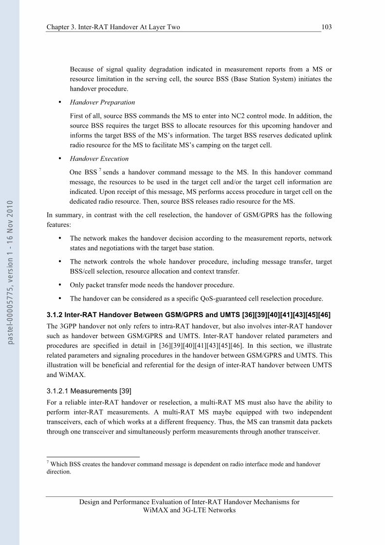
Chapter 3. Inter-RAT Handover At Layer Two
Design and Performance Evaluation of Inter-RAT Handover Mechanisms for WiMAX and 3G-LTE Networks
103
Because of signal quality degradation indicated in measurement reports from a MS or resource limitation in the serving cell, the source BSS (Base Station System) initiates the handover procedure.
• Handover Preparation
First of all, source BSS commands the MS to enter into NC2 control mode. In addition, the source BSS requires the target BSS to allocate resources for this upcoming handover and informs the target BSS of the MS’s information. The target BSS reserves dedicated uplink radio resource for the MS to facilitate MS’s camping on the target cell.
• Handover Execution
One BSS 7 sends a handover command message to the MS. In this handover command message, the resources to be used in the target cell and/or the target cell information are indicated. Upon receipt of this message, MS performs access procedure in target cell on the dedicated radio resource. Then, source BSS releases radio resource for the MS.
In summary, in contrast with the cell reselection, the handover of GSM/GPRS has the following features:
• The network makes the handover decision according to the measurement reports, network states and negotiations with the target base station.
• The network controls the whole handover procedure, including message transfer, target BSS/cell selection, resource allocation and context transfer.
• Only packet transfer mode needs the handover procedure.
• The handover can be considered as a specific QoS-guaranteed cell reselection procedure.
3.1.2 Inter-RAT Handover Between GSM/GPRS and UMTS [36][39][40][41][43][45][46] The 3GPP handover not only refers to intra-RAT handover, but also involves inter-RAT handover such as handover between GSM/GPRS and UMTS. Inter-RAT handover related parameters and procedures are specified in detail in [36][39][40][41][43][45][46]. In this section, we illustrate related parameters and signaling procedures in the handover between GSM/GPRS and UMTS. This illustration will be beneficial and referential for the design of inter-RAT handover between UMTS and WiMAX.
3.1.2.1 Measurements [39] For a reliable inter-RAT handover or reselection, a multi-RAT MS must also have the ability to perform inter-RAT measurements. A multi-RAT MS maybe equipped with two independent transceivers, each of which works at a different frequency. Thus, the MS can transmit data packets through one transceiver and simultaneously perform measurements through another transceiver.
7 Which BSS creates the handover command message is dependent on radio interface mode and handover direction.
past
el-0
0005
775,
ver
sion
1 -
16 N
ov 2
010
104 Chapter 3. Inter-RAT Handover At Layer Two
Design and Performance Evaluation of Inter-RAT Handover Mechanisms for WiMAX and 3G-LTE Networks
If the MS is equipped with only one transceiver, it is also possible for the MS to perform inter-RAT measurements in cellular systems. When a MS camps on a UMTS access network, it can take advantage of the compressed mode [39] to perform measurement during transmission. When the MS camps on a GSM/GPRS network, the compressed mode is not needed any more because GSM/GPRS networks have the dedicated time intervals for measurements [27].
Remark: To simplify system design, in our research project, a MS is assumed to have two independent transceivers: one is UMTS transceiver and another is WiMAX transceiver. Additionally, this MS has data connections with only one network at any time for both battery saving and complexity reduction reasons.
3.1.2.2 System Information (SI) [36][39] The GSM/GPRS/UMTS network regularly broadcasts the related parameters and neighbor cell information on BCCH to facilitate inter-RAT cell reselection and handover. Based on this information, a multi-RAT MS can know how to switch to another RAT. The definitions of System Information (SI) provided in [36][39], are different for GSM/GPRS and UMTS, as shown in Fig. 3-1 and Fig. 3-2.
3.1.2.2.1 MS Camping on a GSM/GPRS Cell [36]
Figure 3-1: System Information for Inter-RAT cell reselection, measurement and handover in GSM
Fig. 3-1 demonstrates the System Information structure [36] for an inter-RAT cell reselection, measurement and handover in GSM. Information about UMTS neighbor cells, such as frequency and bandwidth, is contained in both the SI2ter and SI2quater messages on BCCH. The values of “system information type” field of 2ter and 2quater messages are 0x3 and 0x7 respectively [36]. In addition, the 2quater message also gives some UMTS neighbor cell measurement parameters, as shown in Fig. 3-1.
past
el-0
0005
775,
ver
sion
1 -
16 N
ov 2
010

Chapter 3. Inter-RAT Handover At Layer Two
Design and Performance Evaluation of Inter-RAT Handover Mechanisms for WiMAX and 3G-LTE Networks
105
A MS camping on GPRS can obtain the UMTS neighbor cell information from PSI3quater messages, which is broadcasted in PBCCH.
Remark: Before inter-RAT handover from WiMAX to UMTS, a MS camping on WiMAX shall receive UMTS neighbor cell information, such as carrier frequency and BSIC. This information can be broadcasted regularly in DL-MAP (Downlink Map)/UL-MAP (Uplink Map) and DCD (Downlink Channel Descriptor)/UCD (Uplink Channel Descriptor) messages [51] of WiMAX system.
3.1.2.2.2 MS Camping on a UMTS Cell [39]
Figure 3-2: System Information Blocks for Inter-RAT cell re-selection, measurement and handover in UMTS
In UMTS, system information elements, similar to system information structure of GSM/GPRS, are broadcasted in System Information Block (SIB) [39] on BCCH. Fig. 3-2 shows relevant SIBs for inter-RAT reselection and handover. Measurement control information used by the MS is provided in SIB type 11, 11bis and 12. The Inter-RAT cell information, which contains BCCH frequency and BSIC, is also broadcasted in SIB type 11, 11bis, or 12. This cell information will be stored and used by the MS for cell reselection and handover to GSM/GPRS. Moreover, the SIB type 16 contains predefined configurations of transport and physical channel parameters [39] used by the MS to accelerate handover.
Remark: Before inter-RAT handover from UMTS to WiMAX, the MS camping on UMTS shall receive WiMAX neighbor cell information such as carrier frequency and cell id. This list information can be broadcasted periodically on BCCH in UMTS.
past
el-0
0005
775,
ver
sion
1 -
16 N
ov 2
010
106 Chapter 3. Inter-RAT Handover At Layer Two
Design and Performance Evaluation of Inter-RAT Handover Mechanisms for WiMAX and 3G-LTE Networks
3.1.2.3 Inter-RAT Handover From UMTS to GPRS [43] When a MS camping on a UMTS cell makes handover to GPRS, the inter-RAT handover generally will involve the following procedures (refer to [43] for details).
• Measurements
After a MS finishes the measurements for neighbor cells, it sends measurement results to the network with measurement report messages.
• Handover Preparation
If inter-RAT handover conditions are fulfilled, the source RNC sends relocation request message to target GPRS BSS though SGSNs in the core network. On this message, the SGSN connecting with target BSS reserves resources for this MS. Then the target BSS also allocates radio resources. After that, data packets destined for the MS are received by SGSNs and then forwarded to both the source RNC and target BSS.
• Handover Execution
The target BSS generates an inter-RAT handover command, which is delivered by the source RNC to the MS. Upon receipt of this handover command, the MS performs access procedures on dedicated radio resources in the target cell. On MS presence in the target cell, the SGSNs only forward the packets to the target BSS, and the source RNC releases radio resources for the MS.
Remark: It should be stressed that the conventional 3GPP PS inter-RAT handover procedure must involve SGSN for handover between GPRS and UMTS. This is because that the Link Control Sublayer (LLC), which is in charge of making lossless packet forwarding during MS mobility, terminates at SGSN. For lossless packet forwarding, a retransmission mechanism is implemented at LLC. Therefore, lossless inter-RAT handover between GPRS and UMTS can be realized because the SGSN is their common network entity. But regarding inter-RAT handover between 3GPP cellular network and IEEE wireless IP network such as WIFI/WiMAX, it becomes a challenge to realize a lossless network switch procedure due to the lack of SGSN in IEEE networks.
3.1.3 Conclusion In this section, we survey and summarize the cell reselection and handover features of cellular networks. In the following sections, we utilize the 3GPP PS inter-RAT handover procedure, messages and signaling to resolve handover problems for two typical network coupling architectures: integrated coupling and tight coupling.
3.2 Inter-RAT Handover between UMTS and WiMAX in Integrated Coupling Architecture In order to realize a seamless inter-RAT handover for future B3G or 4G mobile networks, a variety of interworking architectures and inter-RAT handover mobility managements have been proposed. Based on the integrated architecture, in this section, a novel common interworking sublayer (IW sublayer) is proposed at Layer 2 on RNC and MS to provide a seamless PS inter-RAT handover
past
el-0
0005
775,
ver
sion
1 -
16 N
ov 2
010

Chapter 3. Inter-RAT Handover At Layer Two
Design and Performance Evaluation of Inter-RAT Handover Mechanisms for WiMAX and 3G-LTE Networks
107
between UMTS and WiMAX systems. This IW sublayer solution focuses on eliminating packet loss and reducing handover latency that are common problems for most inter-RAT handover scenarios. Compared with other context transfer schemes, as shown in simulation results, the IW sublayer with inter-system retransmission mechanism can achieve a lossless and prompt handover procedure. In addition, this IW sublayer solution can eliminate false fast retransmission of TCP traffics that is usually caused by packet losses or out-of-order packet arrivals. The IW sublayer in tight coupling architectures is specified in section 3.3.
The rest of this section is structured as follows. Sub-clause 3.2.1 addresses the problems that often appear during an inter-RAT handover, and presents some existing solutions. The IW sublayer and its working mechanisms are described in detail in sub-clause 3.2.2. In sub-clause 3.2.3, the simulation scenarios and metrics are specified. The detailed simulation results are given in sub-clause 3.2.4. Finally, conclusions of this section are drawn.
3.2.1 Context Transfer The problems during the inter-RAT handover have been extensively studied in [53-58][60-69], such as long handover latency, BDP (Bandwidth Delay Product) mismatch, delay spikes, packet losses, premature timeout, and false fast retransmission. Among these problems, the packet losses and long handover latency are in particular not desirable for real-time and throughput-sensitive traffics. The most common solution is applying context transfer [57][4] or retransmission [52] [56] mechanisms to accelerate the handover procedure or reduce the amount of lost packets.
PDCP Sequence Number Synchronization [52]: In 3GPP UMTS network [52], the PDCP (Packet Data Convergence Protocol) sublayer is introduced to guarantee reliable data transmission service during a Service Radio Network Subsystem (SRNS) relocation. To be specific, the sequence number synchronization procedure is implemented between PDCP sublayers to avoid any data packet losses during the SRNS relocation. After a successful relocation, the data transmission either resumes from the unconfirmed SDU (Service Data Unit) expected by the peer PDCP entity, or simply resumes from the first unconfirmed SDU.
The PDCP sequence number synchronization mechanism works well when a MS performs SRNS relocation during data transmission in the domain of UMTS. Unfortunately, in the scenario of inter-RAT handover, the PDCP will not take effect any more because:
• The other heterogeneous network systems, especially the IEEE 802-based networks such as WiMAX or WIFI, usually do not have the similar mechanism.
• Even if a PDCP similar mechanism is defined or added in existing WiMAX MAC (Medium Access Control) sublayer, the WiMAX system has its own IP packet header compression mechanism rather than ROHC [52] of UMTS. If the packets or frames stored in the source system with their particular sub-headers (including signaling parts) were forwarded to the target system directly, the target system might discard these unreadable packets or frames, which would induce sequence number de-synchronization and break down ongoing communication connections.
past
el-0
0005
775,
ver
sion
1 -
16 N
ov 2
010
108 Chapter 3. Inter-RAT Handover At Layer Two
Design and Performance Evaluation of Inter-RAT Handover Mechanisms for WiMAX and 3G-LTE Networks
In a word, the sequence number synchronization, header compression and retransmission mechanism of respective RATs complicate the inter-RAT handover procedure instead.
Buffering-and-Forwarding [4]: We have mentioned in chapter 2 that the FMIPv6 [4] eliminates packet losses during a handover by utilizing buffering-and-forwarding mechanism (B&F) to forward unsent packets at IP layer from PAR to NAR. In this IP layer solution, the unsent frames stored at link layer of one RAT usually cannot be retrieved to the IP layer. During a handover, these unsent frames could be lost even unsent packets at IP layer are forwarded to a target network. So, generally, there exist packet losses if a handover management protocol with only B&F mechanism is realized at IP layer or above.
SDU Reconstruction [57]: J. Sachs [57] proposes the SDU Reconstruction scheme. In order to make a lossless handover, the segments stored in the PDU (Packet Data Unit) buffer of source link are first reconstructed back to SDUs and then forwarded to the target link with the SDUs from the SDU buffer. When this scheme is applied to the inter-RAT handover between UMTS and WiMAX at link layer for the TCP traffic, the traffic performance may still degrade, for the following reasons:
• A SDU whose corresponding PDUs have not be successfully transmitted in total, cannot be reconstructed and will be discarded locally, because the successfully transmitted PDUs have already been removed before.
• If SDU Reconstruction scheme is realized at a lower sublayer than UMTS PDCP or WiMAX CS sublayer, this SDU reconstruction implementation could be very complicated. In this case, the SDU Reconstruction scheme demands UMTS PDCP and WiMAX CS sublayer functions to be as simple as possible. For instance, UMTS PDCP shall be configured in transparent mode (not attach any PDCP header, no header compression and no sequence number synchronization). Obviously, this could degrade wireless link performance of two networks during an inter-RAT handover.
R-LLC [56]: In [56] a novel sublayer called R-LLC (Remote Link Layer Control) locating on the BTS (Base Transceiver Station) for handover between GPRS and WIFI is proposed. This R-LLC sublayer takes the role of conventional LLC and implements retransmission mechanism. During a handover period in the downlink, a retransmission timer is set for a transmitted packet at R-LLC sublayer. If the acknowledgement corresponding to a transmitted packet cannot be received before its retransmission timer expiration, R-LLC retransmits this unacknowledged packet that is lost during the handover. The simulation results in [56] demonstrate zero packet loss for handover and cell reselection procedures. Unfortunately, the packet loss is only indicated by retransmission timer timeout, which is set to 5sec. Such a long period is unfavorable to keep TCP congestion window from shrinking. In addition, the configuration of retransmission window size is not specified. So, buffer overflow at lower layers is unavoidable. Moreover, inter-RAT handover execution mechanism at R-LLC is not specified in [56].
In what follows, we will provide a novel and more applicable inter-RAT handover scheme at Layer 2 for the TCP traffic.
past
el-0
0005
775,
ver
sion
1 -
16 N
ov 2
010

Chapter 3. Inter-RAT Handover At Layer Two
Design and Performance Evaluation of Inter-RAT Handover Mechanisms for WiMAX and 3G-LTE Networks
109
3.2.2 IW Sublayer
3.2.2.1 IEEE 802.21 Limitations As introduced in sub-clause 2.1.4.5, IEEE 802.21 [79] is a promising standard to realize handover between different access networks. However, simply applying IEEE 802.21 framework to UMTS-WiMAX integrated and tight coupling architectures does not necessarily bring satisfactory handover performance. In IEEE 802.21 standard, for coupling 802-based networks with cellular networks, generally the MIH PoS (Point of Service) resides deeper inside the access or core networks. Hence, when a MS connects to a 3GPP network such as UMTS, it uses Layer 3 IP transport to conduct signaling or messages exchanges [79]. This becomes a problem for UMTS-WiMAX integrated coupling architecture, because the Layer 3 (IP layer) terminates at SGSN network entity, which is not included in this coupling architecture. In addition, IEEE 802.21 MIHF only defines abstract service model in control plane and it does not specify the actual handover execution mechanism. Therefore, how to design an effective handover execution mechanism in user plane remains an implementation issue.
In our project, in consideration of the advanced features and limitations of IEEE 802.21 framework, a novel IEEE 802.21 MIHF variant is proposed to realize a seamless inter-RAT handover procedure for integrated and tight coupling architectures. Different from conventional IEEE 802.21 MIHF, this MIHF variant is deployed in both control plane and user plane. In the user plane, it introduces a new inter-system retransmission mechanism and applies cross-layer mechanism to resolve packet loss and long handover latency problems. In control plane, it simplifies MIHF services model by only defining a few cross-layer triggers and information from lower layers or to upper layers. In order to differentiate it from standardized MIHF framework, this MIHF variant is renamed InterWorking (IW) sublayer scheme. We will illustrate the flexibility and suitability of the IW sublayer solution for future heterogeneous wireless networks in this section.
3.2.2.2 IW Sublayer Description For a reliable, feasible and seamless handover procedure, a couple of principles shall be taken into account: firstly, because of the fact that cellular networks are very successful and deployed for many years, the integration is based on UMTS network. Secondly, in order to reduce realization complexity and deployment time, we shall modify UMTS and WiMAX respective functions and protocol stacks as few as possible. Thirdly, our UMTS-WiMAX integrated network may provide satisfactory handover performance at cost of necessary modifications to respective networks.
As stated above, our inter-RAT handover solution is first based on the integrated coupling architecture. We assume UMTS to be the master home network with roaming privileges to WiMAX network. A novel common network entity named IW sublayer is introduced on top of PDCP sublayer of UMTS and MAC CS sublayer of WiMAX on the RNC and MS, as shown in Fig. 3-3. The WiMAX BS (Base Station) is integrated with the RNC (Radio Network Controller) through Iub interface. The IW takes the role of LLC sublayer of conventional cellular networks, such as retransmission mechanism and handover support. The main functions of IW sublayer are:
past
el-0
0005
775,
ver
sion
1 -
16 N
ov 2
010
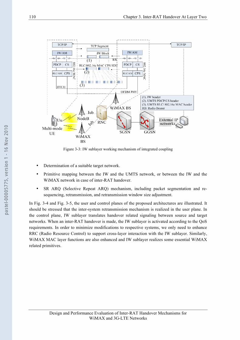
110 Chapter 3. Inter-RAT Handover At Layer Two
Design and Performance Evaluation of Inter-RAT Handover Mechanisms for WiMAX and 3G-LTE Networks
Figure 3-3: IW sublayer working mechanism of integrated coupling
• Determination of a suitable target network.
• Primitive mapping between the IW and the UMTS network, or between the IW and the WiMAX network in case of inter-RAT handover.
• SR ARQ (Selective Repeat ARQ) mechanism, including packet segmentation and re-sequencing, retransmission, and retransmission window size adjustment.
In Fig. 3-4 and Fig. 3-5, the user and control planes of the proposed architectures are illustrated. It should be stressed that the inter-system retransmission mechanism is realized in the user plane. In the control plane, IW sublayer translates handover related signaling between source and target networks. When an inter-RAT handover is made, the IW sublayer is activated according to the QoS requirements. In order to minimize modifications to respective systems, we only need to enhance RRC (Radio Resource Control) to support cross-layer interaction with the IW sublayer. Similarly, WiMAX MAC layer functions are also enhanced and IW sublayer realizes some essential WiMAX related primitives.
past
el-0
0005
775,
ver
sion
1 -
16 N
ov 2
010
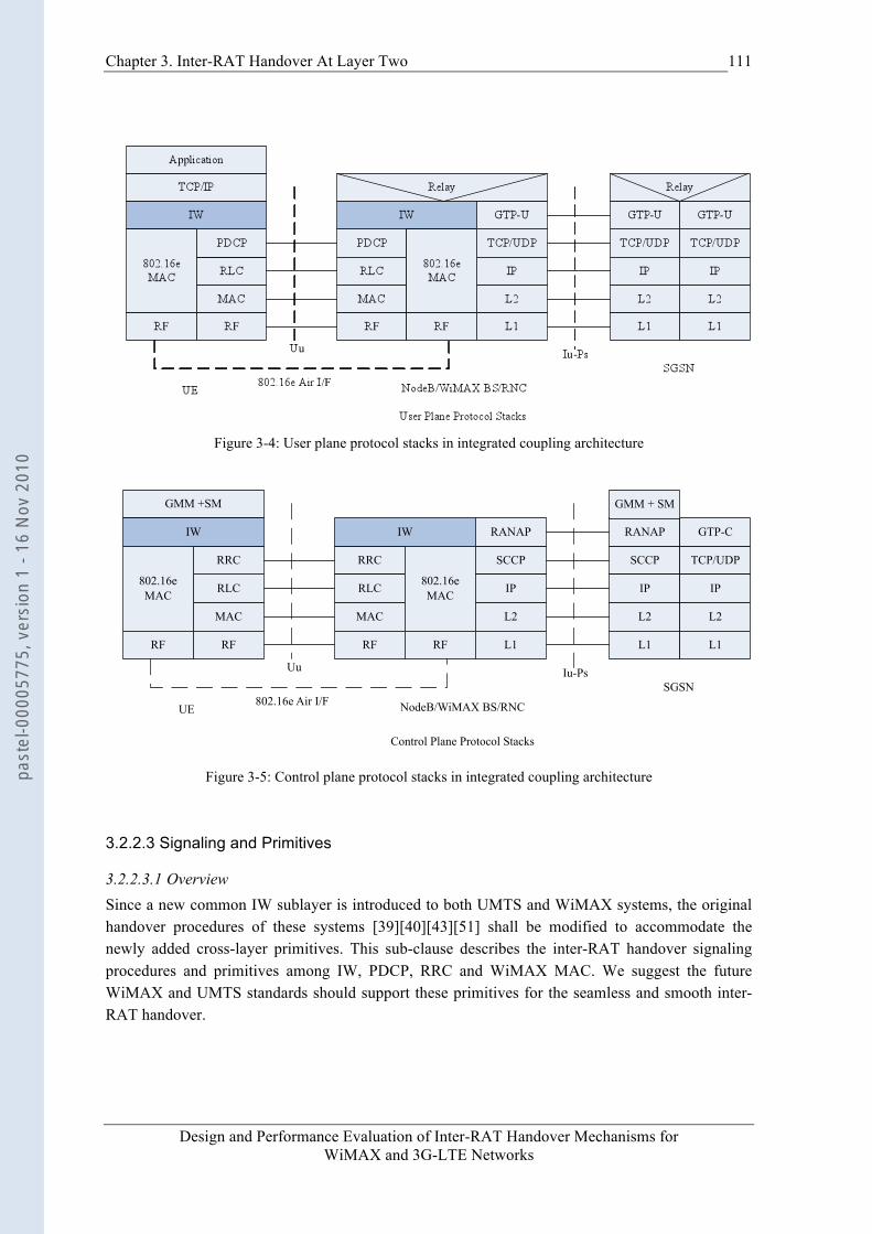
Chapter 3. Inter-RAT Handover At Layer Two
Design and Performance Evaluation of Inter-RAT Handover Mechanisms for WiMAX and 3G-LTE Networks
111
Figure 3-4: User plane protocol stacks in integrated coupling architecture
MAC
RLC
RF
RRC
UE NodeB/WiMAX BS/RNC
GMM +SM
IW
802.16e MAC
RF
RRC
IW
MAC
RF
RLC 802.16e MAC
RF
SCCP
L2
L1
IP
RANAP
SCCP
L2
L1
IP
RANAP
TCP/UDP
L2
L1
IP
GTP-C
SGSN802.16e Air I/F
Uu Iu-Ps
Control Plane Protocol Stacks
GMM + SM
Figure 3-5: Control plane protocol stacks in integrated coupling architecture
3.2.2.3 Signaling and Primitives
3.2.2.3.1 Overview Since a new common IW sublayer is introduced to both UMTS and WiMAX systems, the original handover procedures of these systems [39][40][43][51] shall be modified to accommodate the newly added cross-layer primitives. This sub-clause describes the inter-RAT handover signaling procedures and primitives among IW, PDCP, RRC and WiMAX MAC. We suggest the future WiMAX and UMTS standards should support these primitives for the seamless and smooth inter-RAT handover.
past
el-0
0005
775,
ver
sion
1 -
16 N
ov 2
010
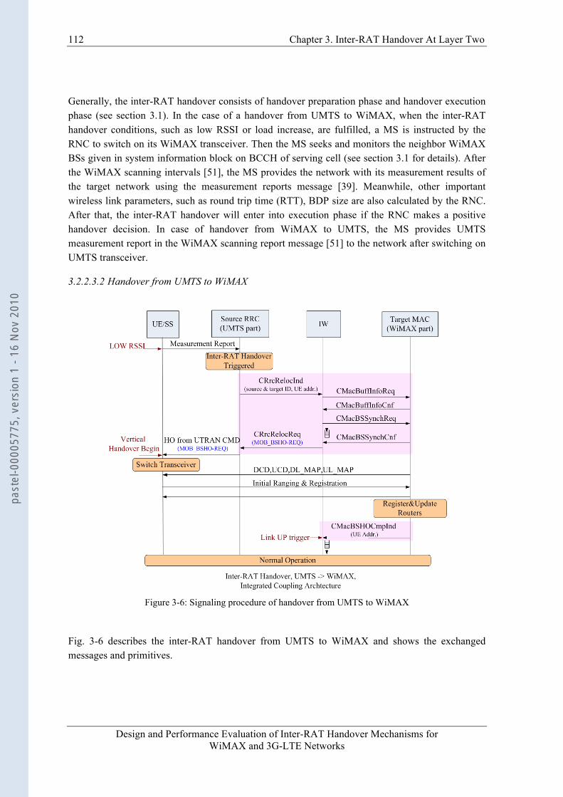
112 Chapter 3. Inter-RAT Handover At Layer Two
Design and Performance Evaluation of Inter-RAT Handover Mechanisms for WiMAX and 3G-LTE Networks
Generally, the inter-RAT handover consists of handover preparation phase and handover execution phase (see section 3.1). In the case of a handover from UMTS to WiMAX, when the inter-RAT handover conditions, such as low RSSI or load increase, are fulfilled, a MS is instructed by the RNC to switch on its WiMAX transceiver. Then the MS seeks and monitors the neighbor WiMAX BSs given in system information block on BCCH of serving cell (see section 3.1 for details). After the WiMAX scanning intervals [51], the MS provides the network with its measurement results of the target network using the measurement reports message [39]. Meanwhile, other important wireless link parameters, such as round trip time (RTT), BDP size are also calculated by the RNC. After that, the inter-RAT handover will enter into execution phase if the RNC makes a positive handover decision. In case of handover from WiMAX to UMTS, the MS provides UMTS measurement report in the WiMAX scanning report message [51] to the network after switching on UMTS transceiver.
3.2.2.3.2 Handover from UMTS to WiMAX
Figure 3-6: Signaling procedure of handover from UMTS to WiMAX
Fig. 3-6 describes the inter-RAT handover from UMTS to WiMAX and shows the exchanged messages and primitives.
past
el-0
0005
775,
ver
sion
1 -
16 N
ov 2
010

Chapter 3. Inter-RAT Handover At Layer Two
Design and Performance Evaluation of Inter-RAT Handover Mechanisms for WiMAX and 3G-LTE Networks
113
1) Based on measurement reports and knowledge of the RAN topology, the RNC, more precisely RRC decides to initiate an inter-RAT handover.
2) RRC sends the CRrcRelocInd primitive (contains target WiMAX cell id) to the IW sublayer.
3) Then, the IW sublayer sends the CMacBuffInfoReq primitive to the target WiMAX MAC to request the buffer characteristics. The WiMAX MAC shall return the CMacBuffInfoCnf primitive to inform the IW sublayer of the buffer size in its MAC sublayer. According to this information, the IW sublayer adjusts its retransmission window size. (Note that current WiMAX MAC does not support this interface, so the IW sublayer may adjust its retransmission window size to a default value).
4) At this stage, the IW sublayer sends the CMacBSSynchReq primitive to the WiMAX MAC to negotiate the location of the dedicated initial ranging transmission opportunity for the MS. This information is returned in primitive CMacBSSynchCnf.
5) After that, the IW sublayer suspends data transmission and buffers data packets that require delivery order. Meanwhile, it sends a CRrcRelocReq primitive (including transparent container (MOB_BSHO-REQ)) to RRC.
6) RRC sends the Handover from UTRAN Command message to the MS, which includes the MOB_BSHO-REQ.
7) The MS performs hard handover and normal WiMAX network entry procedure.
8) After the provisioned service flow is activated [51], the target WiMAX MAC sends CMacBSHOCmpInd primitive as a Link_Up trigger to the IW sublayer. On this trigger, the IW sublayer shall restart data packet forwarding.
3.2.2.3.3 Handover from WiMAX to UMTS The inter-RAT handover from WiMAX to UMTS is described in Fig. 3-7.
1) After the scanning interval, the MS sends scanning report to WiMAX serving BS in message MOB_SCN-REP that contains physical information such as mean RSSI.
2) The source WiMAX MAC sends CMacBSHOInd primitive to inform the IW sublayer of target cell id. The IW sublayer then sends CPdcpBuffInfoReq primitive to RRC of the UMTS network. RRC shall return the CPdcpBuffInfoCnf primitive to inform the IW sublayer of buffer size and buffer occupation. According to this information, the IW sublayer adjusts its retransmission window size.
3) The IW sublayer sends a CRrcRelocReq primitive to RRC to apply for resource allocation. The result is returned in CRrcRelocCnf primitive by RRC.
4) Upon receipt of the CRrcRelocCnf, the IW sublayer suspends data transmission and buffers data packets that require delivery order.
past
el-0
0005
775,
ver
sion
1 -
16 N
ov 2
010
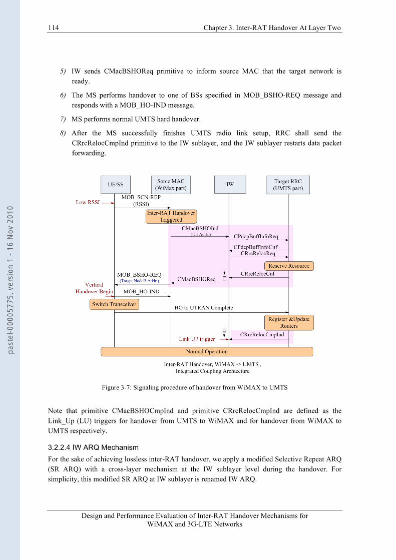
114 Chapter 3. Inter-RAT Handover At Layer Two
Design and Performance Evaluation of Inter-RAT Handover Mechanisms for WiMAX and 3G-LTE Networks
5) IW sends CMacBSHOReq primitive to inform source MAC that the target network is ready.
6) The MS performs handover to one of BSs specified in MOB_BSHO-REQ message and responds with a MOB_HO-IND message.
7) MS performs normal UMTS hard handover.
8) After the MS successfully finishes UMTS radio link setup, RRC shall send the CRrcRelocCmpInd primitive to the IW sublayer, and the IW sublayer restarts data packet forwarding.
Figure 3-7: Signaling procedure of handover from WiMAX to UMTS
Note that primitive CMacBSHOCmpInd and primitive CRrcRelocCmpInd are defined as the Link_Up (LU) triggers for handover from UMTS to WiMAX and for handover from WiMAX to UMTS respectively.
3.2.2.4 IW ARQ Mechanism For the sake of achieving lossless inter-RAT handover, we apply a modified Selective Repeat ARQ (SR ARQ) with a cross-layer mechanism at the IW sublayer level during the handover. For simplicity, this modified SR ARQ at IW sublayer is renamed IW ARQ.
past
el-0
0005
775,
ver
sion
1 -
16 N
ov 2
010
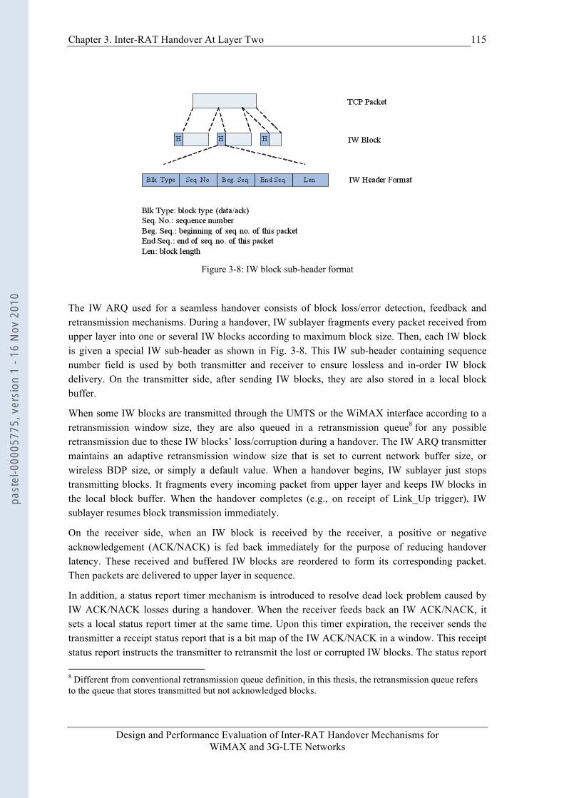
Chapter 3. Inter-RAT Handover At Layer Two
Design and Performance Evaluation of Inter-RAT Handover Mechanisms for WiMAX and 3G-LTE Networks
115
Figure 3-8: IW block sub-header format
The IW ARQ used for a seamless handover consists of block loss/error detection, feedback and retransmission mechanisms. During a handover, IW sublayer fragments every packet received from upper layer into one or several IW blocks according to maximum block size. Then, each IW block is given a special IW sub-header as shown in Fig. 3-8. This IW sub-header containing sequence number field is used by both transmitter and receiver to ensure lossless and in-order IW block delivery. On the transmitter side, after sending IW blocks, they are also stored in a local block buffer.
When some IW blocks are transmitted through the UMTS or the WiMAX interface according to a retransmission window size, they are also queued in a retransmission queue8 for any possible retransmission due to these IW blocks’ loss/corruption during a handover. The IW ARQ transmitter maintains an adaptive retransmission window size that is set to current network buffer size, or wireless BDP size, or simply a default value. When a handover begins, IW sublayer just stops transmitting blocks. It fragments every incoming packet from upper layer and keeps IW blocks in the local block buffer. When the handover completes (e.g., on receipt of Link_Up trigger), IW sublayer resumes block transmission immediately.
On the receiver side, when an IW block is received by the receiver, a positive or negative acknowledgement (ACK/NACK) is fed back immediately for the purpose of reducing handover latency. These received and buffered IW blocks are reordered to form its corresponding packet. Then packets are delivered to upper layer in sequence.
In addition, a status report timer mechanism is introduced to resolve dead lock problem caused by IW ACK/NACK losses during a handover. When the receiver feeds back an IW ACK/NACK, it sets a local status report timer at the same time. Upon this timer expiration, the receiver sends the transmitter a receipt status report that is a bit map of the IW ACK/NACK in a window. This receipt status report instructs the transmitter to retransmit the lost or corrupted IW blocks. The status report 8 Different from conventional retransmission queue definition, in this thesis, the retransmission queue refers to the queue that stores transmitted but not acknowledged blocks.
past
el-0
0005
775,
ver
sion
1 -
16 N
ov 2
010

116 Chapter 3. Inter-RAT Handover At Layer Two
Design and Performance Evaluation of Inter-RAT Handover Mechanisms for WiMAX and 3G-LTE Networks
timer duration is set to a default system parameter, e.g., 2.5sec. Moreover, when an abnormal handover takes place (e.g., Link_Up trigger is lost or long delayed), status report timer mechanism can eliminate data packet losses after system recovers from this abnormal handover procedure.
Compared with conventional SR ARQ mechanism, the IW ARQ has following new features:
• Receiver-Driven scheme: the ACK/NACK is sent back by receiver initiatively on receipt of an IW block without transmitter’s polling message.
• Support Link_Up trigger: when a handover is finished, the target network will signal the IW sublayer with a Link_Up trigger. On receipt of this trigger, the IW sublayer will retransmit blocks in retransmission queue to avoid unnecessary waiting for a timeout of status report timer.
• Adaptive Window Size: In order to avoid any buffer overflow in the target network when the IW sublayer retransmits the unacknowledged blocks on Link_Up trigger, the IW ARQ retransmission window size can be adaptively set to target network wireless BDP sizes, or lower layer buffer size.
1 2 3 121110987654
ack
ack Hard handover period
43
ack
5 6 7
LinkUP
Retransmit buffer
Window Size
ack
ack
Retransmission Timer duration
43
ack
5 6 7ac
kac
k
Window Size
IW ARQ scheme R-LLC scheme
IW sublayer on RNC
IW sublayer on MS
8 9 10
Figure 3-9: IW ARQ and R-LLC: a example of time evolution
In Fig. 3-9, an example of the IW ARQ mechanism is depicted. On Link_Up trigger, the IW sublayer retransmits unacknowledged blocks from sequence number 3. The R-LLC retransmission scheme is also depicted on the right part of this figure. In this figure, the differences between IW ARQ and R-LLC can be noticed. Firstly, the lost blocks are retransmitted when retransmission timers expire in R-LLC scheme. While in IW ARQ mechanism, lost blocks are retransmitted not only on status report timer expiration but also on Link_Up trigger. Secondly, the amount of unacknowledged blocks is limited to the retransmission window size during handover procedure in IW ARQ mechanism, while there is no retransmission window mechanism in R-LLC.
past
el-0
0005
775,
ver
sion
1 -
16 N
ov 2
010
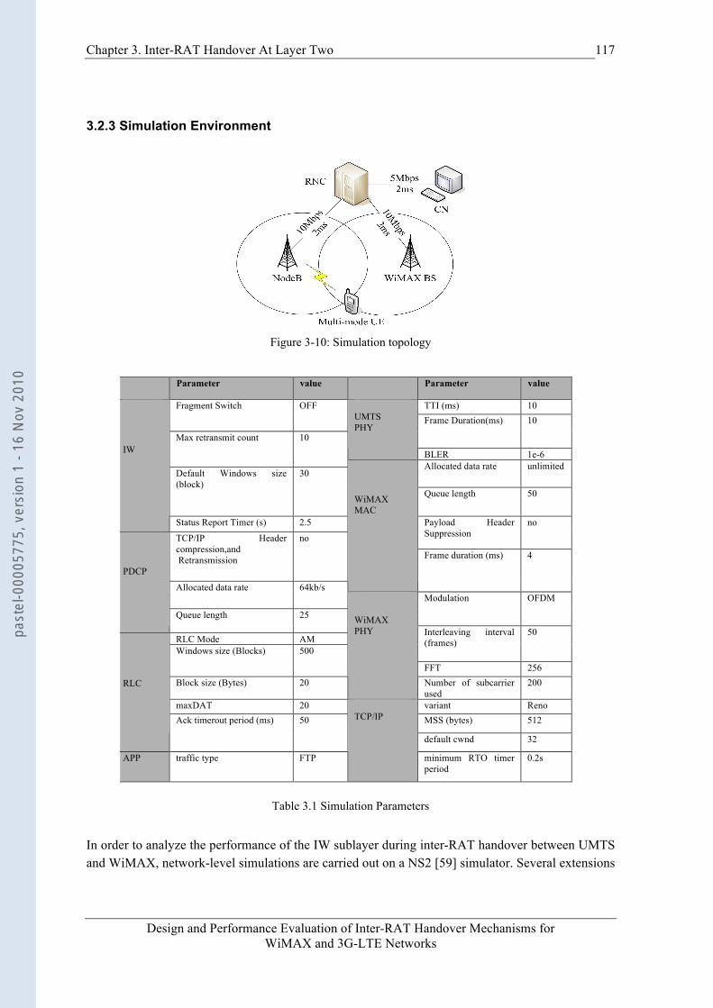
Chapter 3. Inter-RAT Handover At Layer Two
Design and Performance Evaluation of Inter-RAT Handover Mechanisms for WiMAX and 3G-LTE Networks
117
3.2.3 Simulation Environment
Figure 3-10: Simulation topology
Table 3.1 Simulation Parameters
In order to analyze the performance of the IW sublayer during inter-RAT handover between UMTS and WiMAX, network-level simulations are carried out on a NS2 [59] simulator. Several extensions
Parameter value Parameter value
TTI (ms) 10 Fragment Switch OFF Frame Duration(ms) 10
UMTS PHY
BLER 1e-6
Max retransmit count 10
Allocated data rate unlimited Default Windows size (block)
30
Queue length 50
IW
Status Report Timer (s) 2.5 Payload Header Suppression
no
TCP/IP Header compression,and Retransmission
no
WiMAX MAC
Frame duration (ms) 4
Allocated data rate 64kb/s Modulation OFDM
PDCP
Queue length 25
RLC Mode AM Interleaving interval (frames)
50
Windows size (Blocks) 500
FFT 256 Block size (Bytes) 20
WiMAX PHY
Number of subcarrier used
200
maxDAT 20 variant Reno MSS (bytes) 512
RLC
Ack timerout period (ms) 50
default cwnd 32
APP traffic type FTP
TCP/IP
minimum RTO timer period
0.2s
past
el-0
0005
775,
ver
sion
1 -
16 N
ov 2
010

118 Chapter 3. Inter-RAT Handover At Layer Two
Design and Performance Evaluation of Inter-RAT Handover Mechanisms for WiMAX and 3G-LTE Networks
are added to this simulator, such as UMTS and WiMAX models, IW sublayer, multi-channel model, IW ARQ mechanism and new signaling and primitives. The topology used for simulation analysis is illustrated in Fig. 3-10. There is only one MS with UMTS and WiMAX transceivers. Additionally, there are no other background traffics in this scenario since we focus on handover mechanisms in radio access networks. So, the MS always has bandwidth to send packets whether it is in WiMAX region or in UMTS region.
Note that in this topology, the transmission delays in the wired network are set very small deliberately in order to minimize their influences on handover procedures. The FTP packets flowing from CN to MS are observed in this simulator. In the UMTS module, a drop-tail policy is applied to radio network queue in PDCP and this queue length is set to 25 IW blocks. In the WiMAX module, the queue length is set to 50 IW blocks, which considers the fact that generally the bandwidth of WiMAX is higher. Other important simulation parameters are summarized in Table 3-1. We focus on the problems of packet loss and handover latency, while BDP mismatch, spurious RTO problems for the TCP traffics will be covered in the next chapter.
3.2.4 Simulation Results
3.2.4.1 Handover from UMTS to WIMAX
Figure 3-11: TCP segment number comparison (umts->wimax, sender side)
past
el-0
0005
775,
ver
sion
1 -
16 N
ov 2
010
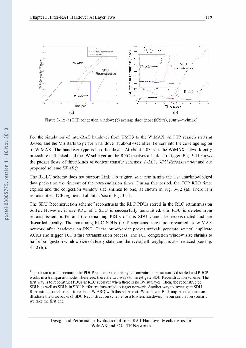
Chapter 3. Inter-RAT Handover At Layer Two
Design and Performance Evaluation of Inter-RAT Handover Mechanisms for WiMAX and 3G-LTE Networks
119
0 1 2 3 4 5 6 7 8 90
10
20
30
40
50
60
70
80
90
Time (sec.)
TCP
Con
gest
ion
Win
dow
R LLCSDU ReconstructionIW ARQ
R LLC
SDU Reconstruction
IW ARQ
(a) (b)
Figure 3-12: (a) TCP congestion window; (b) average throughput (Kbit/s), (umts->wimax)
For the simulation of inter-RAT handover from UMTS to the WiMAX, an FTP session starts at 0.4sec, and the MS starts to perform handover at about 4sec after it enters into the coverage region of WiMAX. The handover type is hard handover. At about 4.035sec, the WiMAX network entry procedure is finished and the IW sublayer on the RNC receives a Link_Up trigger. Fig. 3-11 shows the packet flows of three kinds of context transfer schemes: R-LLC, SDU Reconstruction and our proposed scheme IW ARQ.
The R-LLC scheme does not support Link_Up trigger, so it retransmits the last unacknowledged data packet on the timeout of the retransmission timer. During this period, the TCP RTO timer expires and the congestion window size shrinks to one, as shown in Fig. 3-12 (a). There is a retransmitted TCP segment at about 5.7sec in Fig. 3-11.
The SDU Reconstruction scheme 9 reconstructs the RLC PDUs stored in the RLC retransmission buffer. However, if one PDU of a SDU is successfully transmitted, this PDU is deleted from retransmission buffer and the remaining PDUs of this SDU cannot be reconstructed and are discarded locally. The remaining RLC SDUs (TCP segments here) are forwarded to WiMAX network after handover on RNC. These out-of-order packet arrivals generate several duplicate ACKs and trigger TCP’s fast retransmission process. The TCP congestion window size shrinks to half of congestion window size of steady state, and the average throughput is also reduced (see Fig. 3-12 (b)).
9 In our simulation scenario, the PDCP sequence number synchronization mechanism is disabled and PDCP works in a transparent mode. Therefore, there are two ways to investigate SDU Reconstruction scheme. The first way is to reconstruct PDUs at RLC sublayer when there is no IW sublayer. Then, the reconstructed SDUs as well as SDUs in SDU buffer are forwarded to target network. Another way to investigate SDU Reconstruction scheme is to replace IW ARQ with this scheme at IW sublayer. Both implementations can illustrate the drawbacks of SDU Reconstruction scheme for a lossless handover. In our simulation scenario, we take the first one.
past
el-0
0005
775,
ver
sion
1 -
16 N
ov 2
010
120 Chapter 3. Inter-RAT Handover At Layer Two
Design and Performance Evaluation of Inter-RAT Handover Mechanisms for WiMAX and 3G-LTE Networks
The IW ARQ scheme adjusts its retransmission window size according to the target network’s queue size and forwards the unacknowledged IW blocks in its retransmission queue on receipt of Link_Up trigger. After handover, there are no packet losses and the TCP ACK arrivals are not as bursty as those of SDU Reconstruction scheme thanks to the IW ARQ retransmission window mechanism (see Fig. 3-11 between 4sec and 4.1sec).
3.2.4.2 Handover from WiMAX to UMTS A typical problem during handover procedure from high-speed WiMAX network to relatively low speed UMTS network is buffer overflow, which is caused by BDP mismatch between these two networks. The UMTS network is likely to undergo buffer overflow when the TCP congestion window size becomes much larger in WiMAX than the buffer allocation for a MS in UMTS RNC.
In SDU Reconstruction scheme, the buffered packets forwarded from WiMAX to UMTS may have the probability to overflow the UMTS buffer, because the buffer in WiMAX may store more packets than the UMTS buffer size. For SDU Reconstruction scheme, in Fig.3-13, the buffer overflow in UMTS after handover leads to TCP retransmission starting at about 6.0sec. The TCP congestion window shrinks, as shown in Fig. 3-14 (a).
In R-LLC scheme, the long local retransmission timer period leads to the TCP RTO timer expiration, and the TCP sender retransmits a segment for three times before this local retransmission timer expires 10.
As for IW ARQ scheme, the support of Link_Up trigger accelerates handover response time, and the adaptive IW ARQ retransmission window size effectively eliminates buffer overflow in the target UMTS network. It can be seen that the lossless handover of IW ARQ scheme has a “side effect”: eliminating the false fast retransmission caused by packet losses or out-of-order packet arrivals during a handover.
In Fig. 3-14 (b), the average throughput differences for three schemes are not distinct in short-term, because the total amount of throughput is dominated by that of WiMAX and the small throughput reduction during handover period does not influence the average throughput significantly.
3.2.5 Conclusion This section elaborate a novel Layer 2 inter-RAT handover solution on basis of the integrated coupling architecture for the seamless roaming between UMTS and WiMAX networks. At Layer 2, a new sublayer, named IW sublayer, which lies on the RNC and MS, is added on top of PDCP (UMTS) and MAC (WiMAX) sublayer. Compared with other context transfer schemes, such as R-LLC and SDU Reconstruction, IW sublayer can achieve lossless and prompt handover procedure for TCP traffics thanks to the introduction of inter-system retransmission mechanism. The simulation results carried out on NS2 emulator validate the better handover performance. In addition, this novel IW sublayer solution also eliminates the false fast retransmission that is due to packet losses or out-of-order packet arrivals during a handover.
10 In our simulation scenario, this local retransmission timer period is set to 2.5sec.
past
el-0
0005
775,
ver
sion
1 -
16 N
ov 2
010
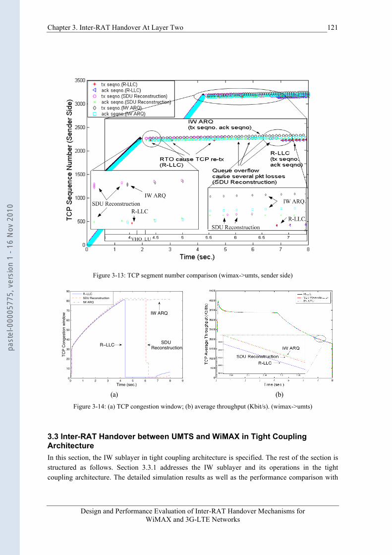
Chapter 3. Inter-RAT Handover At Layer Two
Design and Performance Evaluation of Inter-RAT Handover Mechanisms for WiMAX and 3G-LTE Networks
121
Figure 3-13: TCP segment number comparison (wimax->umts, sender side)
0 1 2 3 4 5 6 7 8 90
10
20
30
40
50
60
70
80
90
Time (sec.)
TCP
Con
gest
ion
win
dow
R LLCSDU ReconstructionIW ARQ
R LLC SDU Reconstruction
IW ARQ
(a) (b)
Figure 3-14: (a) TCP congestion window; (b) average throughput (Kbit/s). (wimax->umts)
3.3 Inter-RAT Handover between UMTS and WiMAX in Tight Coupling Architecture In this section, the IW sublayer in tight coupling architecture is specified. The rest of the section is structured as follows. Section 3.3.1 addresses the IW sublayer and its operations in the tight coupling architecture. The detailed simulation results as well as the performance comparison with
past
el-0
0005
775,
ver
sion
1 -
16 N
ov 2
010
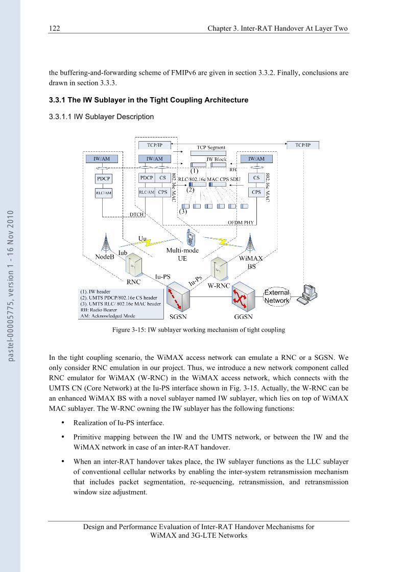
122 Chapter 3. Inter-RAT Handover At Layer Two
Design and Performance Evaluation of Inter-RAT Handover Mechanisms for WiMAX and 3G-LTE Networks
the buffering-and-forwarding scheme of FMIPv6 are given in section 3.3.2. Finally, conclusions are drawn in section 3.3.3.
3.3.1 The IW Sublayer in the Tight Coupling Architecture
3.3.1.1 IW Sublayer Description
Figure 3-15: IW sublayer working mechanism of tight coupling
In the tight coupling scenario, the WiMAX access network can emulate a RNC or a SGSN. We only consider RNC emulation in our project. Thus, we introduce a new network component called RNC emulator for WiMAX (W-RNC) in the WiMAX access network, which connects with the UMTS CN (Core Network) at the Iu-PS interface shown in Fig. 3-15. Actually, the W-RNC can be an enhanced WiMAX BS with a novel sublayer named IW sublayer, which lies on top of WiMAX MAC sublayer. The W-RNC owning the IW sublayer has the following functions:
• Realization of Iu-PS interface.
• Primitive mapping between the IW and the UMTS network, or between the IW and the WiMAX network in case of an inter-RAT handover.
• When an inter-RAT handover takes place, the IW sublayer functions as the LLC sublayer of conventional cellular networks by enabling the inter-system retransmission mechanism that includes packet segmentation, re-sequencing, retransmission, and retransmission window size adjustment.
past
el-0
0005
775,
ver
sion
1 -
16 N
ov 2
010
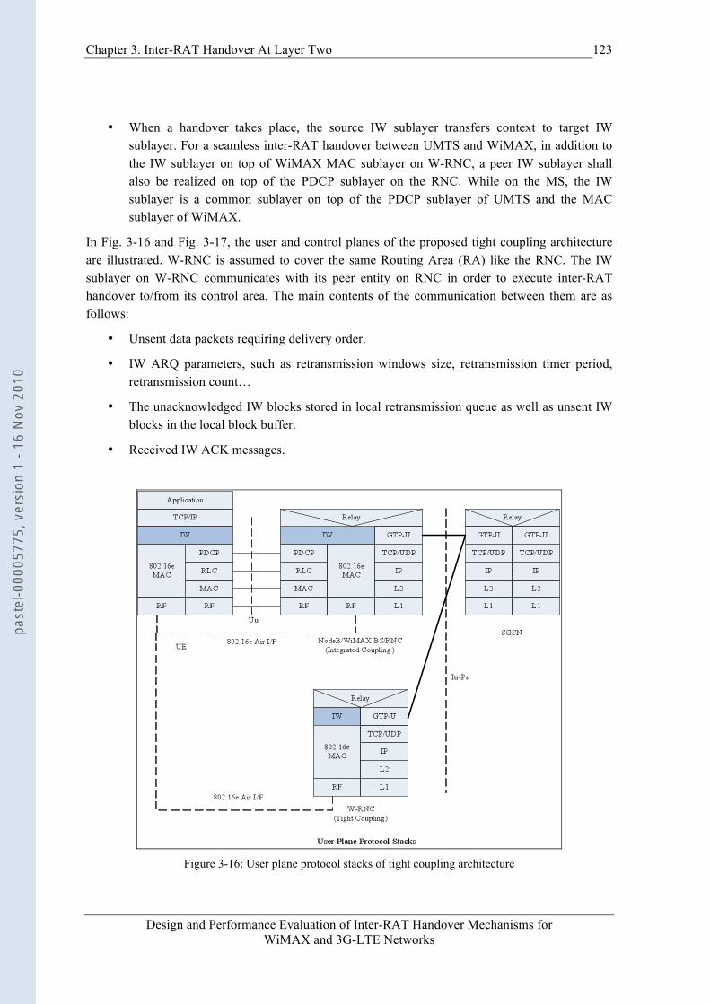
Chapter 3. Inter-RAT Handover At Layer Two
Design and Performance Evaluation of Inter-RAT Handover Mechanisms for WiMAX and 3G-LTE Networks
123
• When a handover takes place, the source IW sublayer transfers context to target IW sublayer. For a seamless inter-RAT handover between UMTS and WiMAX, in addition to the IW sublayer on top of WiMAX MAC sublayer on W-RNC, a peer IW sublayer shall also be realized on top of the PDCP sublayer on the RNC. While on the MS, the IW sublayer is a common sublayer on top of the PDCP sublayer of UMTS and the MAC sublayer of WiMAX.
In Fig. 3-16 and Fig. 3-17, the user and control planes of the proposed tight coupling architecture are illustrated. W-RNC is assumed to cover the same Routing Area (RA) like the RNC. The IW sublayer on W-RNC communicates with its peer entity on RNC in order to execute inter-RAT handover to/from its control area. The main contents of the communication between them are as follows:
• Unsent data packets requiring delivery order.
• IW ARQ parameters, such as retransmission windows size, retransmission timer period, retransmission count…
• The unacknowledged IW blocks stored in local retransmission queue as well as unsent IW blocks in the local block buffer.
• Received IW ACK messages.
Figure 3-16: User plane protocol stacks of tight coupling architecture
past
el-0
0005
775,
ver
sion
1 -
16 N
ov 2
010
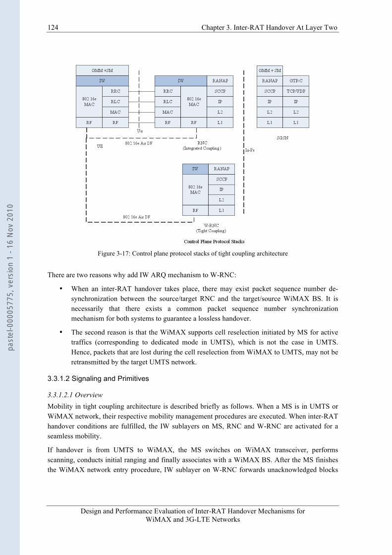
124 Chapter 3. Inter-RAT Handover At Layer Two
Design and Performance Evaluation of Inter-RAT Handover Mechanisms for WiMAX and 3G-LTE Networks
Figure 3-17: Control plane protocol stacks of tight coupling architecture
There are two reasons why add IW ARQ mechanism to W-RNC:
• When an inter-RAT handover takes place, there may exist packet sequence number de-synchronization between the source/target RNC and the target/source WiMAX BS. It is necessarily that there exists a common packet sequence number synchronization mechanism for both systems to guarantee a lossless handover.
• The second reason is that the WiMAX supports cell reselection initiated by MS for active traffics (corresponding to dedicated mode in UMTS), which is not the case in UMTS. Hence, packets that are lost during the cell reselection from WiMAX to UMTS, may not be retransmitted by the target UMTS network.
3.3.1.2 Signaling and Primitives
3.3.1.2.1 Overview Mobility in tight coupling architecture is described briefly as follows. When a MS is in UMTS or WiMAX network, their respective mobility management procedures are executed. When inter-RAT handover conditions are fulfilled, the IW sublayers on MS, RNC and W-RNC are activated for a seamless mobility.
If handover is from UMTS to WiMAX, the MS switches on WiMAX transceiver, performs scanning, conducts initial ranging and finally associates with a WiMAX BS. After the MS finishes the WiMAX network entry procedure, IW sublayer on W-RNC forwards unacknowledged blocks
past
el-0
0005
775,
ver
sion
1 -
16 N
ov 2
010
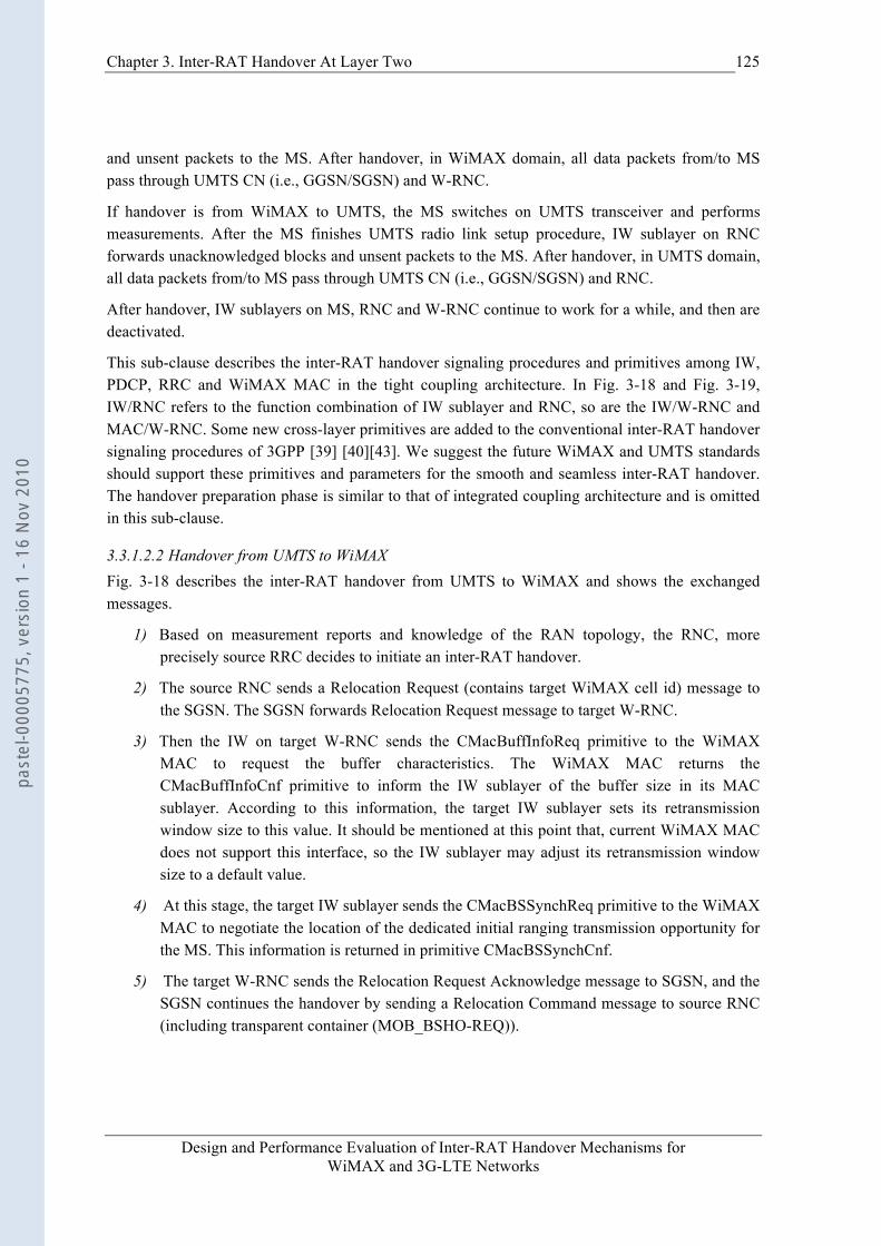
Chapter 3. Inter-RAT Handover At Layer Two
Design and Performance Evaluation of Inter-RAT Handover Mechanisms for WiMAX and 3G-LTE Networks
125
and unsent packets to the MS. After handover, in WiMAX domain, all data packets from/to MS pass through UMTS CN (i.e., GGSN/SGSN) and W-RNC.
If handover is from WiMAX to UMTS, the MS switches on UMTS transceiver and performs measurements. After the MS finishes UMTS radio link setup procedure, IW sublayer on RNC forwards unacknowledged blocks and unsent packets to the MS. After handover, in UMTS domain, all data packets from/to MS pass through UMTS CN (i.e., GGSN/SGSN) and RNC.
After handover, IW sublayers on MS, RNC and W-RNC continue to work for a while, and then are deactivated.
This sub-clause describes the inter-RAT handover signaling procedures and primitives among IW, PDCP, RRC and WiMAX MAC in the tight coupling architecture. In Fig. 3-18 and Fig. 3-19, IW/RNC refers to the function combination of IW sublayer and RNC, so are the IW/W-RNC and MAC/W-RNC. Some new cross-layer primitives are added to the conventional inter-RAT handover signaling procedures of 3GPP [39] [40][43]. We suggest the future WiMAX and UMTS standards should support these primitives and parameters for the smooth and seamless inter-RAT handover. The handover preparation phase is similar to that of integrated coupling architecture and is omitted in this sub-clause.
3.3.1.2.2 Handover from UMTS to WiMAX Fig. 3-18 describes the inter-RAT handover from UMTS to WiMAX and shows the exchanged messages.
1) Based on measurement reports and knowledge of the RAN topology, the RNC, more precisely source RRC decides to initiate an inter-RAT handover.
2) The source RNC sends a Relocation Request (contains target WiMAX cell id) message to the SGSN. The SGSN forwards Relocation Request message to target W-RNC.
3) Then the IW on target W-RNC sends the CMacBuffInfoReq primitive to the WiMAX MAC to request the buffer characteristics. The WiMAX MAC returns the CMacBuffInfoCnf primitive to inform the IW sublayer of the buffer size in its MAC sublayer. According to this information, the target IW sublayer sets its retransmission window size to this value. It should be mentioned at this point that, current WiMAX MAC does not support this interface, so the IW sublayer may adjust its retransmission window size to a default value.
4) At this stage, the target IW sublayer sends the CMacBSSynchReq primitive to the WiMAX MAC to negotiate the location of the dedicated initial ranging transmission opportunity for the MS. This information is returned in primitive CMacBSSynchCnf.
5) The target W-RNC sends the Relocation Request Acknowledge message to SGSN, and the SGSN continues the handover by sending a Relocation Command message to source RNC (including transparent container (MOB_BSHO-REQ)).
past
el-0
0005
775,
ver
sion
1 -
16 N
ov 2
010

126 Chapter 3. Inter-RAT Handover At Layer Two
Design and Performance Evaluation of Inter-RAT Handover Mechanisms for WiMAX and 3G-LTE Networks
Figure 3-18: Signaling procedure of the handover from UMTS to WiMAX
6) Upon receipt of this message, the IW sublayer on source RNC will forward IW context to target IW sublayer on W-RNC. The IW context consists of IW ARQ parameters, received IW ACKs and remaining IW blocks that have not been transmitted successfully.
7) The RRC on the source RNC sends the Handover from UTRAN Command message to the MS.
8) The MS performs hard handover and normal network entry procedure.
9) After the provisioned service flow is activated, the target WiMAX MAC sends CMacBSHOCmpInd primitive as a Link_Up trigger to the IW sublayer. On this trigger, the IW sublayer starts data block forwarding immediately.
3.3.1.2.3 Handover from WiMAX to UMTS The inter-RAT handover from WiMAX to UMTS is described in Fig. 3-19.
1) After the scanning interval, the MS sends scanning report to WiMAX serving BS in message MOB_SCN-REP that contains physical information such as mean RSSI.
past
el-0
0005
775,
ver
sion
1 -
16 N
ov 2
010
Chapter 3. Inter-RAT Handover At Layer Two
Design and Performance Evaluation of Inter-RAT Handover Mechanisms for WiMAX and 3G-LTE Networks
127
Figure 3-19: Signaling procedure of the handover from WiMAX to UMTS
2) The source WiMAX MAC sends CMacBSHOInd primitive to inform the IW sublayer of handover and target cell id. Then, the source W-RNC sends a Relocation Request (contains target cell id) message to the SGSN. The SGSN forwards Relocation Request message to target RNC.
3) The IW sublayer on target RNC sends CPdcpBuffInfoReq primitive to the RRC sublayer to request the buffer characteristics of the PDCP sublayer, and RRC returns the CPdcpBuffInfoCnf primitive to inform the IW sublayer of the buffer size. According to this information, the IW sublayer sets its retransmission window size to this value.
4) The target IW sublayer sends a CRrcRelocReq primitive to the target RRC to apply for resource allocation. The result is returned in CRrcRelocCnf primitive by the target RRC.
5) The target RNC sends the Relocation Request Acknowledge message (contains target RNC to source W-RNC transparent Container) to SGSN. The SGSN continues the handover by sending a Relocation Command message to source W-RNC.
6) On receipt of Relocation Command message, the IW sublayer on source W-RNC forwards IW context to the IW sublayer on target RNC. The IW context consists of IW ARQ parameters, received IW ACKs, and remaining IW blocks that have not been transmitted successfully.
7) The source IW sublayer sends CMacBSHOReq primitive to inform WiMAX MAC that the target network is ready.
past
el-0
0005
775,
ver
sion
1 -
16 N
ov 2
010
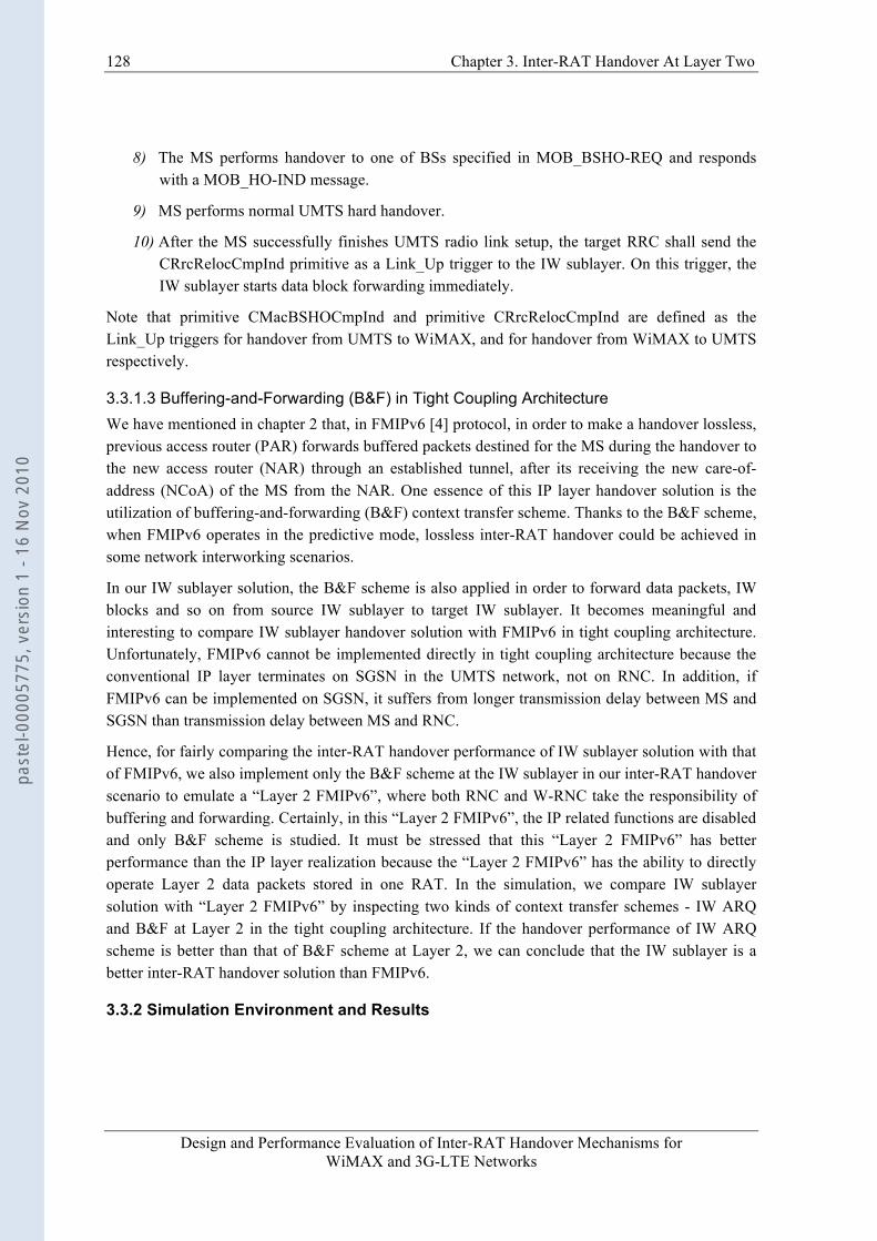
128 Chapter 3. Inter-RAT Handover At Layer Two
Design and Performance Evaluation of Inter-RAT Handover Mechanisms for WiMAX and 3G-LTE Networks
8) The MS performs handover to one of BSs specified in MOB_BSHO-REQ and responds with a MOB_HO-IND message.
9) MS performs normal UMTS hard handover.
10) After the MS successfully finishes UMTS radio link setup, the target RRC shall send the CRrcRelocCmpInd primitive as a Link_Up trigger to the IW sublayer. On this trigger, the IW sublayer starts data block forwarding immediately.
Note that primitive CMacBSHOCmpInd and primitive CRrcRelocCmpInd are defined as the Link_Up triggers for handover from UMTS to WiMAX, and for handover from WiMAX to UMTS respectively.
3.3.1.3 Buffering-and-Forwarding (B&F) in Tight Coupling Architecture We have mentioned in chapter 2 that, in FMIPv6 [4] protocol, in order to make a handover lossless, previous access router (PAR) forwards buffered packets destined for the MS during the handover to the new access router (NAR) through an established tunnel, after its receiving the new care-of-address (NCoA) of the MS from the NAR. One essence of this IP layer handover solution is the utilization of buffering-and-forwarding (B&F) context transfer scheme. Thanks to the B&F scheme, when FMIPv6 operates in the predictive mode, lossless inter-RAT handover could be achieved in some network interworking scenarios.
In our IW sublayer solution, the B&F scheme is also applied in order to forward data packets, IW blocks and so on from source IW sublayer to target IW sublayer. It becomes meaningful and interesting to compare IW sublayer handover solution with FMIPv6 in tight coupling architecture. Unfortunately, FMIPv6 cannot be implemented directly in tight coupling architecture because the conventional IP layer terminates on SGSN in the UMTS network, not on RNC. In addition, if FMIPv6 can be implemented on SGSN, it suffers from longer transmission delay between MS and SGSN than transmission delay between MS and RNC.
Hence, for fairly comparing the inter-RAT handover performance of IW sublayer solution with that of FMIPv6, we also implement only the B&F scheme at the IW sublayer in our inter-RAT handover scenario to emulate a “Layer 2 FMIPv6”, where both RNC and W-RNC take the responsibility of buffering and forwarding. Certainly, in this “Layer 2 FMIPv6”, the IP related functions are disabled and only B&F scheme is studied. It must be stressed that this “Layer 2 FMIPv6” has better performance than the IP layer realization because the “Layer 2 FMIPv6” has the ability to directly operate Layer 2 data packets stored in one RAT. In the simulation, we compare IW sublayer solution with “Layer 2 FMIPv6” by inspecting two kinds of context transfer schemes - IW ARQ and B&F at Layer 2 in the tight coupling architecture. If the handover performance of IW ARQ scheme is better than that of B&F scheme at Layer 2, we can conclude that the IW sublayer is a better inter-RAT handover solution than FMIPv6.
3.3.2 Simulation Environment and Results
past
el-0
0005
775,
ver
sion
1 -
16 N
ov 2
010
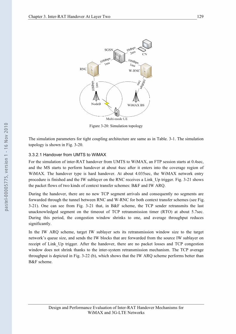
Chapter 3. Inter-RAT Handover At Layer Two
Design and Performance Evaluation of Inter-RAT Handover Mechanisms for WiMAX and 3G-LTE Networks
129
Figure 3-20: Simulation topology
The simulation parameters for tight coupling architecture are same as in Table. 3-1. The simulation topology is shown in Fig. 3-20.
3.3.2.1 Handover from UMTS to WiMAX For the simulation of inter-RAT handover from UMTS to WiMAX, an FTP session starts at 0.4sec, and the MS starts to perform handover at about 4sec after it enters into the coverage region of WiMAX. The handover type is hard handover. At about 4.035sec, the WiMAX network entry procedure is finished and the IW sublayer on the RNC receives a Link_Up trigger. Fig. 3-21 shows the packet flows of two kinds of context transfer schemes: B&F and IW ARQ.
During the handover, there are no new TCP segment arrivals and consequently no segments are forwarded through the tunnel between RNC and W-RNC for both context transfer schemes (see Fig. 3-21). One can see from Fig. 3-21 that, in B&F scheme, the TCP sender retransmits the last unacknowledged segment on the timeout of TCP retransmission timer (RTO) at about 5.7sec. During this period, the congestion window shrinks to one, and average throughput reduces significantly.
In the IW ARQ scheme, target IW sublayer sets its retransmission window size to the target network’s queue size, and sends the IW blocks that are forwarded from the source IW sublayer on receipt of Link_Up trigger. After the handover, there are no packet losses and TCP congestion window does not shrink thanks to the inter-system retransmission mechanism. The TCP average throughput is depicted in Fig. 3-22 (b), which shows that the IW ARQ scheme performs better than B&F scheme.
past
el-0
0005
775,
ver
sion
1 -
16 N
ov 2
010
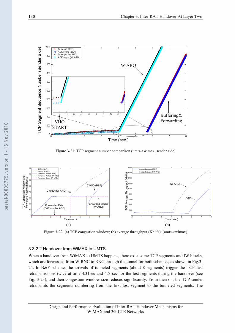
130 Chapter 3. Inter-RAT Handover At Layer Two
Design and Performance Evaluation of Inter-RAT Handover Mechanisms for WiMAX and 3G-LTE Networks
Figure 3-21: TCP segment number comparison (umts->wimax, sender side)
0 1 2 3 4 5 6 7 80
10
20
30
40
50
60
70
80
Time (sec.)
TCP
Con
gest
ion
Win
dow
and
Fo
rwar
ded
Pack
ets&
Bloc
ks
CWND (B&F)CWND (IW ARQ)Forwarded Packets (B&F)Forwarded Packets (IW ARQ)Forwarded Blocks (IW ARQ)
Forwarded Blocks (IW ARQ)Forwarded Pkts
(B&F and IW ARQ)
CWND (IW ARQ)
CWND (B&F)
0 1 2 3 4 5 6 7 80
200
400
600
800
1000
1200
1400
1600
1800
Time (sec.)
TCP
Aver
age
Thro
ughp
ut (K
bit/s
)
Average throughput(B&F)Average throughput(IW ARQ)
IW ARQ
B&F
(a) (b)
Figure 3-22: (a) TCP congestion window; (b) average throughput (Kbit/s), (umts->wimax)
3.3.2.2 Handover from WiMAX to UMTS When a handover from WiMAX to UMTS happens, there exist some TCP segments and IW blocks, which are forwarded from W-RNC to RNC through the tunnel for both schemes, as shown in Fig.3-24. In B&F scheme, the arrivals of tunneled segments (about 8 segments) trigger the TCP fast retransmissions twice at time 4.31sec and 4.51sec for the lost segments during the handover (see Fig. 3-23), and then congestion window size reduces significantly. From then on, the TCP sender retransmits the segments numbering from the first lost segment to the tunneled segments. The
past
el-0
0005
775,
ver
sion
1 -
16 N
ov 2
010
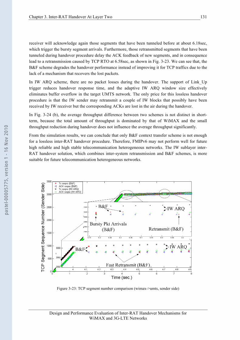
Chapter 3. Inter-RAT Handover At Layer Two
Design and Performance Evaluation of Inter-RAT Handover Mechanisms for WiMAX and 3G-LTE Networks
131
receiver will acknowledge again those segments that have been tunneled before at about 6.18sec, which trigger the bursty segment arrivals. Furthermore, those retransmitted segments that have been tunneled during handover procedure delay the ACK feedback of new segments, and in consequence lead to a retransmission caused by TCP RTO at 6.58sec, as shown in Fig. 3-23. We can see that, the B&F scheme degrades the handover performance instead of improving it for TCP traffics due to the lack of a mechanism that recovers the lost packets.
In IW ARQ scheme, there are no packet losses during the handover. The support of Link_Up trigger reduces handover response time, and the adaptive IW ARQ window size effectively eliminates buffer overflow in the target UMTS network. The only price for this lossless handover procedure is that the IW sender may retransmit a couple of IW blocks that possibly have been received by IW receiver but the corresponding ACKs are lost in the air during the handover.
In Fig. 3-24 (b), the average throughput difference between two schemes is not distinct in short-term, because the total amount of throughput is dominated by that of WiMAX and the small throughput reduction during handover does not influence the average throughput significantly.
From the simulation results, we can conclude that only B&F context transfer scheme is not enough for a lossless inter-RAT handover procedure. Therefore, FMIPv6 may not perform well for future high reliable and high stable telecommunication heterogeneous networks. The IW sublayer inter-RAT handover solution, which combines inter-system retransmission and B&F schemes, is more suitable for future telecommunication heterogeneous networks.
Figure 3-23: TCP segment number comparison (wimax->umts, sender side)
past
el-0
0005
775,
ver
sion
1 -
16 N
ov 2
010
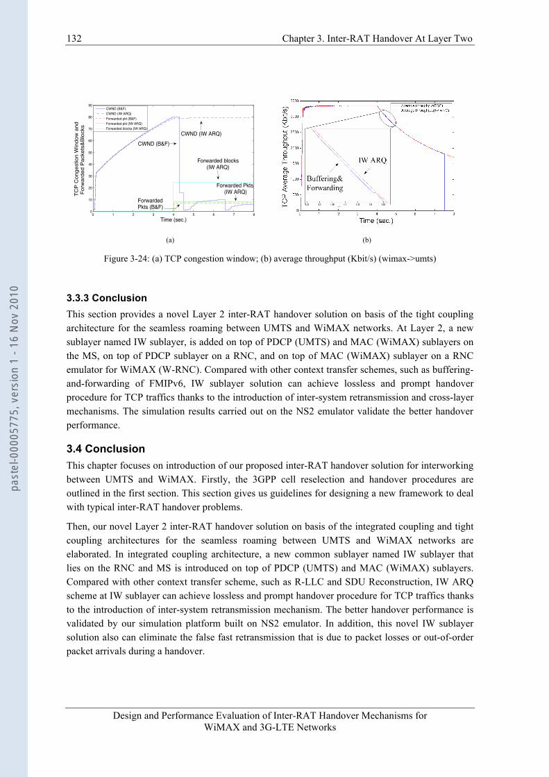
132 Chapter 3. Inter-RAT Handover At Layer Two
Design and Performance Evaluation of Inter-RAT Handover Mechanisms for WiMAX and 3G-LTE Networks
0 1 2 3 4 5 6 7 80
10
20
30
40
50
60
70
80
90
Time (sec.)
TCP
Con
gest
ion
Win
dow
and
Fo
rwar
ded
Pac
kets
&B
lock
s
CWND (B&F)CWND (IW ARQ)Forwarded pkt (B&F)Forwarded pkt (IW ARQ)Forwarded blocks (IW ARQ)
CWND (IW ARQ)CWND (B&F)
Forwarded blocks(IW ARQ)
Forwarded Pkts (IW ARQ)
ForwardedPkts (B&F)
(a) (b)
Figure 3-24: (a) TCP congestion window; (b) average throughput (Kbit/s) (wimax->umts)
3.3.3 Conclusion This section provides a novel Layer 2 inter-RAT handover solution on basis of the tight coupling architecture for the seamless roaming between UMTS and WiMAX networks. At Layer 2, a new sublayer named IW sublayer, is added on top of PDCP (UMTS) and MAC (WiMAX) sublayers on the MS, on top of PDCP sublayer on a RNC, and on top of MAC (WiMAX) sublayer on a RNC emulator for WiMAX (W-RNC). Compared with other context transfer schemes, such as buffering-and-forwarding of FMIPv6, IW sublayer solution can achieve lossless and prompt handover procedure for TCP traffics thanks to the introduction of inter-system retransmission and cross-layer mechanisms. The simulation results carried out on the NS2 emulator validate the better handover performance.
3.4 Conclusion This chapter focuses on introduction of our proposed inter-RAT handover solution for interworking between UMTS and WiMAX. Firstly, the 3GPP cell reselection and handover procedures are outlined in the first section. This section gives us guidelines for designing a new framework to deal with typical inter-RAT handover problems.
Then, our novel Layer 2 inter-RAT handover solution on basis of the integrated coupling and tight coupling architectures for the seamless roaming between UMTS and WiMAX networks are elaborated. In integrated coupling architecture, a new common sublayer named IW sublayer that lies on the RNC and MS is introduced on top of PDCP (UMTS) and MAC (WiMAX) sublayers. Compared with other context transfer scheme, such as R-LLC and SDU Reconstruction, IW ARQ scheme at IW sublayer can achieve lossless and prompt handover procedure for TCP traffics thanks to the introduction of inter-system retransmission mechanism. The better handover performance is validated by our simulation platform built on NS2 emulator. In addition, this novel IW sublayer solution also can eliminate the false fast retransmission that is due to packet losses or out-of-order packet arrivals during a handover.
past
el-0
0005
775,
ver
sion
1 -
16 N
ov 2
010
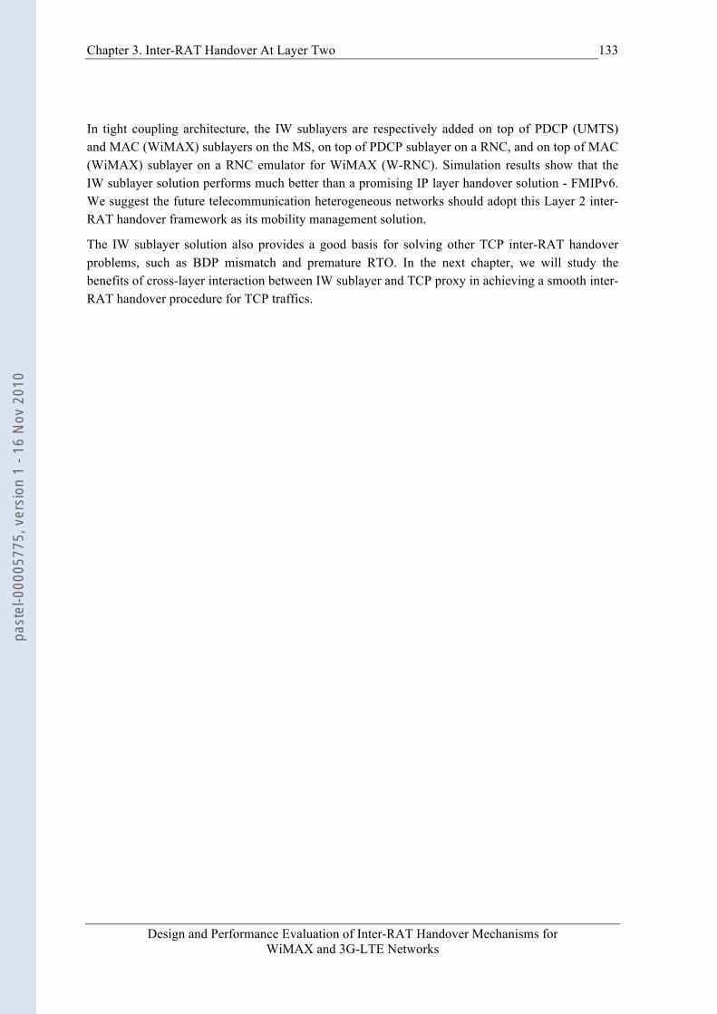
Chapter 3. Inter-RAT Handover At Layer Two
Design and Performance Evaluation of Inter-RAT Handover Mechanisms for WiMAX and 3G-LTE Networks
133
In tight coupling architecture, the IW sublayers are respectively added on top of PDCP (UMTS) and MAC (WiMAX) sublayers on the MS, on top of PDCP sublayer on a RNC, and on top of MAC (WiMAX) sublayer on a RNC emulator for WiMAX (W-RNC). Simulation results show that the IW sublayer solution performs much better than a promising IP layer handover solution - FMIPv6. We suggest the future telecommunication heterogeneous networks should adopt this Layer 2 inter-RAT handover framework as its mobility management solution.
The IW sublayer solution also provides a good basis for solving other TCP inter-RAT handover problems, such as BDP mismatch and premature RTO. In the next chapter, we will study the benefits of cross-layer interaction between IW sublayer and TCP proxy in achieving a smooth inter-RAT handover procedure for TCP traffics.
past
el-0
0005
775,
ver
sion
1 -
16 N
ov 2
010

Design and Performance Evaluation of Inter-RAT Handover Mechanisms for WiMAX and 3G-LTE Networks
CHAPTER 4 TCP PROXY FOR INTER-RAT HANDOVER
In the former chapter, based on integrated and tight coupling architectures, we propose a novel common interworking sublayer (IW sublayer) at Layer 2 on RNC, W-RNC and MS to provide a seamless inter-RAT handover between UMTS and WiMAX systems. This IW sublayer solution focuses on eliminating packet losses and reducing handover latency.
Packet loss and long handover latency are common problems for most inter-RAT handover scenarios. For TCP traffics, there are some other specific handover problems. In this chapter, two kinds of snoop agents, which interact with the IW sublayer, are also introduced on RNC to solve two typical inter-RAT handover problems for the TCP traffic: BDP (Bandwidth Delay Product) mismatch and spurious RTO (Retransmission TimeOut). In this thesis, these snoop agents are renamed TCP Proxies. The first kind of TCP Proxy is applicable to a frequent handover scenario (e.g., a MS moves back and forth in a cell boundary). The second kind of TCP Proxy is applicable to an occasional handover scenario, regardless of the long-lived or short-lived traffic. Compared with other conventional vertical handover solutions, our novel inter-RAT total solution has the merits of keeping existing TCP protocol stacks unchanged and being robust to different handover scenarios.
The rest of the chapter is structured as follows. Section 4.1 gives an overview of TCP specific problems in a handover procedure. In section 4.2, the working mechanism of TCP Proxy for frequent handover scenario and its interactions with IW sublayer are specified in detail. In section 4.3, an enhanced TCP Proxy for the occasional handover scenario is specified. Finally, conclusions are drawn in section 4.4.
4.1 TCP Specific Handover Problems The problems about inter-RAT handover have been extensively studied by numerous literatures [60-67]. These problems, such as long handover latency, BDP mismatch, delay spikes, packet losses, premature timeout, false fast retransmission and spurious RTO [60], cannot be resolved in total by only one scheme at a time. In order to simplify analysis, we group them into two typical types: the packet losses/long handover latency, and BDP mismatch/spurious RTO. Regarding the first type problems, we have proposed IW sublayer in the former chapter to resolve them. Regarding the second type problems, there exist many solutions. These solutions are generally classified into network-centric and receiver-centric approaches.
past
el-0
0005
775,
ver
sion
1 -
16 N
ov 2
010
Chapter 4. TCP Proxy For Inter-RAT Handover
Design and Performance Evaluation of Inter-RAT Handover Mechanisms for WiMAX and 3G-LTE Networks
135
4.1.1 Receiver-centric Approaches Reference [61] proposes to add an explicit handover notification in the option field of TCP header to indicate the handover situation. Obviously, this scheme needs significant modification over the existing TCP protocol stacks. In [62], a receiver based vertical handover scheme is proposed. In this scheme, the negative impacts of abrupt BDP change after handover is eliminated if the receiver has knowledge of target network BDP size and can modify the receiver’s advertised window field in an ACK message. However, this scheme uses MIPv6 as the mobility management protocol. As a consequence, the packet loss problem cannot be fixed by this scheme itself but by TCP retransmission mechanism. Freeze-TCP [63] utilizes ZWA (Zero Window Advertisement) message to force the TCP sender to freeze retransmission timer and enter persist mode when a handover is forthcoming. This scheme requires the TCP receiver to calculate a precise “warning period” [63]. Any imprecise calculation of “warning period” will lead to early ZWA arrival before handover, or delayed ZWA arrival after handover occurrence. In [60], the TCP RTO timeout problem due to long vertical handover latency is fixed by using timestamp in WP-TCP header. Certainly, this scheme is not applicable to other existing TCP variants.
It should be noted that, reference [64] proposes to delay the RTT (Round Trip Time) iteratively to a proper value at network layer before a vertical handover in order to avoid premature timeout. Unfortunately, the RTO algorithm and parameters in TCP sender must be available to TCP receiver, and the period of “soft-handover” [64] should be long enough to accommodate the RTO adjustment procedure.
4.1.2 Network-centric Approaches In M-TCP [66], the Freeze-TCP [63] mechanism is utilized in base station. The old and new base stations take the responsibilities of making TCP sender enter into and exit persist mode. Unfortunately, M-TCP is designed for horizontal handover and does not consider the wireless link BDP and RTT variations. In [92], a proxy entity locating between TCP sender and access network is introduced to overcome problems of TCP traffic starting in a WCDMA access network with large BDP size. In [93], the proxy is used to improve TCP tracking performance when link bandwidth changes. In [67] and [94], a snoop agent is proposed at link layer on base station. It has knowledge of TCP protocol and ensures TCP packet transmission over wireless links. Lost packets can be retransmitted by the snoop agent. However, the snoop agent is not designed for handover among heterogeneous wireless networks.
Network-centric approaches have the advantage of being transparent to both TCP sides in comparison with receiver-centric approaches. Furthermore, the snoop agent can take advantage of TCP knowledge and cross-layer information from lower sublayers. For these reasons, in this chapter, we propose a total solution by combing snoop agent and IW sublayer framework for solving second type handover problems. The snoop agent having cross-layer interactions with IW sublayer in this thesis is renamed TCP Proxy.
For simplicity, we make the following assumptions:
• Again, only the downlink direction is considered.
past
el-0
0005
775,
ver
sion
1 -
16 N
ov 2
010
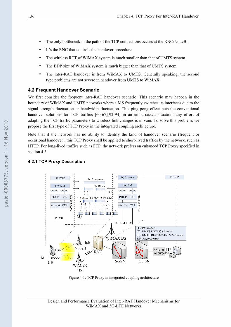
136 Chapter 4. TCP Proxy For Inter-RAT Handover
Design and Performance Evaluation of Inter-RAT Handover Mechanisms for WiMAX and 3G-LTE Networks
• The only bottleneck in the path of the TCP connections occurs at the RNC/NodeB.
• It’s the RNC that controls the handover procedure.
• The wireless RTT of WiMAX system is much smaller than that of UMTS system.
• The BDP size of WiMAX system is much bigger than that of UMTS system.
• The inter-RAT handover is from WiMAX to UMTS. Generally speaking, the second type problems are not severe in handover from UMTS to WiMAX.
4.2 Frequent Handover Scenario We first consider the frequent inter-RAT handover scenario. This scenario may happen in the boundary of WiMAX and UMTS networks where a MS frequently switches its interfaces due to the signal strength fluctuation or bandwidth fluctuation. This ping-pong effect puts the conventional handover solutions for TCP traffics [60-67][92-94] in an embarrassed situation: any effort of adapting the TCP traffic parameters to wireless link changes is in vain. To solve this problem, we propose the first type of TCP Proxy in the integrated coupling architecture.
Note that if the network has no ability to identify the kind of handover scenario (frequent or occasional handover), this TCP Proxy shall be applied to short-lived traffics by the network, such as HTTP. For long-lived traffics such as FTP, the network prefers an enhanced TCP Proxy specified in section 4.3.
4.2.1 TCP Proxy Description
Figure 4-1: TCP Proxy in integrated coupling architecture
past
el-0
0005
775,
ver
sion
1 -
16 N
ov 2
010

Chapter 4. TCP Proxy For Inter-RAT Handover
Design and Performance Evaluation of Inter-RAT Handover Mechanisms for WiMAX and 3G-LTE Networks
137
In Fig. 4-1, the TCP Proxy lies on the top of IW sublayer on RNC and has the following features:
1) TCP Proxy is disabled when there is no handover. When an inter-RAT handover becomes possible due to, for example, signal strength degradation, TCP Proxy is enabled and works in the transparent mode. In the transparent mode, a local queue is maintained for the wireless access network. Every incoming TCP segment is buffered in this queue and forwarded to the MS as well. When an ACK is from the MS, TCP Proxy not only forwards ACK to TCP sender, but also deletes the corresponding TCP segments from this local queue.
2) When a handover is forthcoming, IW sublayer sends a handover indication primitive (CIWHOInd, see below sub-clause for details) to TCP Proxy. In this primitive, the MS and target network wireless BDP size are indicated. TCP Proxy sets a local transmission window size to this target network wireless BDP size. The amount of segments forwarded to MS after handover is limited to this local transmission window size in order to avoid any buffer flow at lower sublayers.
3) Then, TCP Proxy sends a TCP ACK message with zero receiver window size (ZWA) to the TCP sender. This ZWA message makes the TCP sender enter into a persist mode. In the persist mode, TCP sender freezes its re-transmission timer and congestion window. When the handover completes, TCP Proxy continuously sends segments to MS until the local queue length is below a target queue length11. Afterwards, TCP Proxy triggers TCP sending by feeding back an ACK message with non-zero receiver’s advertised window size (NZWA).
4) After a handover, when the TCP Proxy receives a new segment from the TCP sender, a corresponding “spoofed” ACK timer is created locally. The timer period is set to the previous wireless RTT of WiMAX (WRTTwimax). On this spoofed ACK timer expiration, the TCP Proxy “spoofs” TCP sender by feeding back a locally generated TCP ACK with a calculated advertised window size.
5) By setting the advertised window field in the TCP spoofed ACK to a calculated value, the TCP Proxy can control TCP transmission in order to maintain a proper local queue length. This calculated value of window size, denoted by Wi(t), is gotten according to the local queue length in TCP Proxy, target queue length and estimated network BDP size.
We use the queue management solution provided in [67] as shown in (4-1), i.e., TCP Proxy only applies a simple feedback mechanism:
Wi(t) = W0(t) + a*(Qt – Q(t)) (4-1)
Where W0(t) is the network (wired and wireless) BDP size estimated by TCP Proxy; the Qt is target queue length in TCP Proxy and Q(t) is current local queue length in TCP Proxy; while the parameter “a” is a constant during a handover procedure.
11 In our simulation scenario, the target queue length is set to target network wireless BDP size.
past
el-0
0005
775,
ver
sion
1 -
16 N
ov 2
010
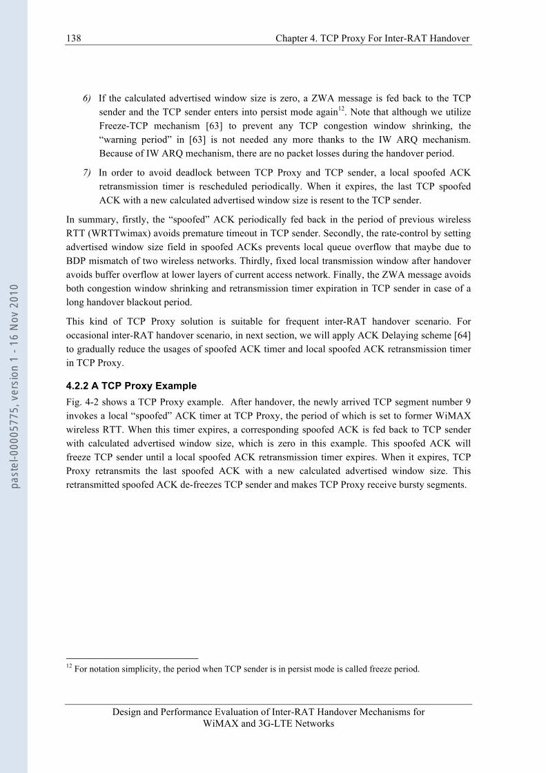
138 Chapter 4. TCP Proxy For Inter-RAT Handover
Design and Performance Evaluation of Inter-RAT Handover Mechanisms for WiMAX and 3G-LTE Networks
6) If the calculated advertised window size is zero, a ZWA message is fed back to the TCP sender and the TCP sender enters into persist mode again12. Note that although we utilize Freeze-TCP mechanism [63] to prevent any TCP congestion window shrinking, the “warning period” in [63] is not needed any more thanks to the IW ARQ mechanism. Because of IW ARQ mechanism, there are no packet losses during the handover period.
7) In order to avoid deadlock between TCP Proxy and TCP sender, a local spoofed ACK retransmission timer is rescheduled periodically. When it expires, the last TCP spoofed ACK with a new calculated advertised window size is resent to the TCP sender.
In summary, firstly, the “spoofed” ACK periodically fed back in the period of previous wireless RTT (WRTTwimax) avoids premature timeout in TCP sender. Secondly, the rate-control by setting advertised window size field in spoofed ACKs prevents local queue overflow that maybe due to BDP mismatch of two wireless networks. Thirdly, fixed local transmission window after handover avoids buffer overflow at lower layers of current access network. Finally, the ZWA message avoids both congestion window shrinking and retransmission timer expiration in TCP sender in case of a long handover blackout period.
This kind of TCP Proxy solution is suitable for frequent inter-RAT handover scenario. For occasional inter-RAT handover scenario, in next section, we will apply ACK Delaying scheme [64] to gradually reduce the usages of spoofed ACK timer and local spoofed ACK retransmission timer in TCP Proxy.
4.2.2 A TCP Proxy Example Fig. 4-2 shows a TCP Proxy example. After handover, the newly arrived TCP segment number 9 invokes a local “spoofed” ACK timer at TCP Proxy, the period of which is set to former WiMAX wireless RTT. When this timer expires, a corresponding spoofed ACK is fed back to TCP sender with calculated advertised window size, which is zero in this example. This spoofed ACK will freeze TCP sender until a local spoofed ACK retransmission timer expires. When it expires, TCP Proxy retransmits the last spoofed ACK with a new calculated advertised window size. This retransmitted spoofed ACK de-freezes TCP sender and makes TCP Proxy receive bursty segments.
12 For notation simplicity, the period when TCP sender is in persist mode is called freeze period.
past
el-0
0005
775,
ver
sion
1 -
16 N
ov 2
010
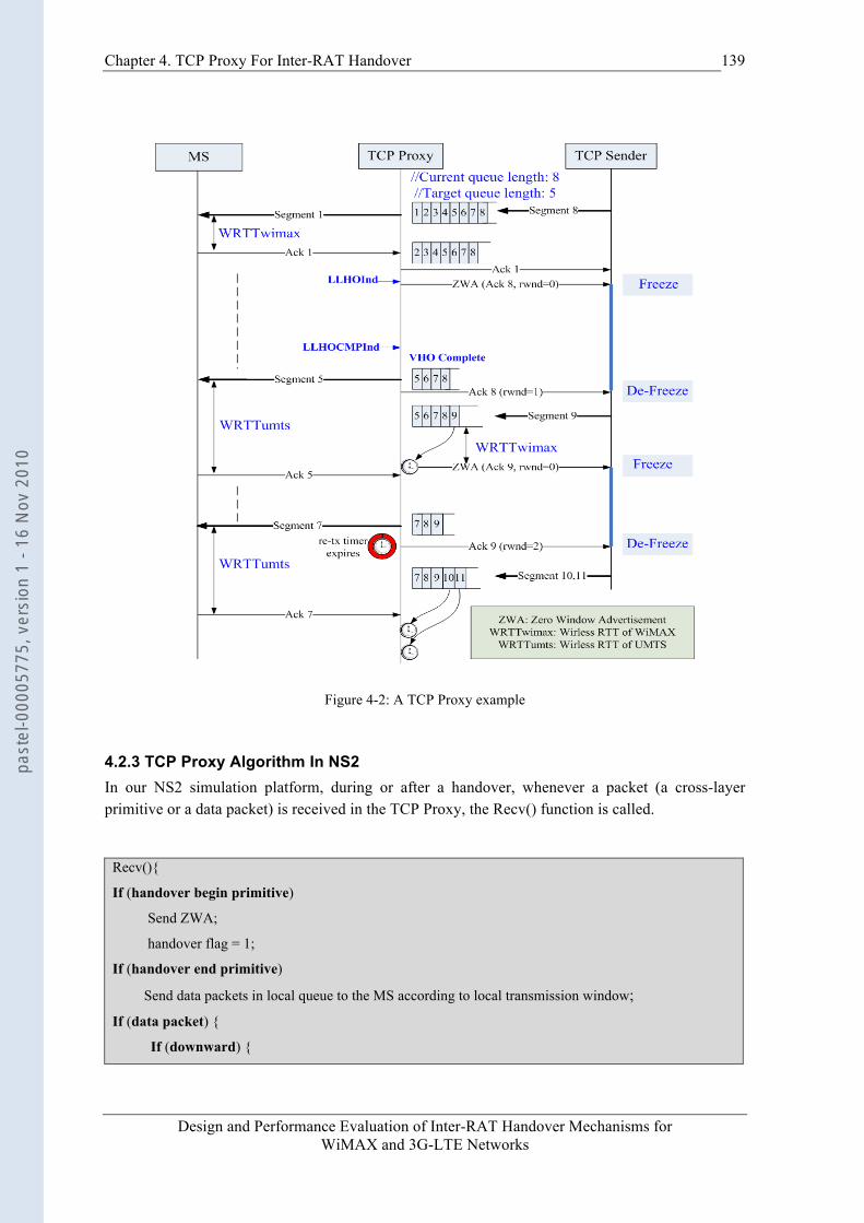
Chapter 4. TCP Proxy For Inter-RAT Handover
Design and Performance Evaluation of Inter-RAT Handover Mechanisms for WiMAX and 3G-LTE Networks
139
Figure 4-2: A TCP Proxy example
4.2.3 TCP Proxy Algorithm In NS2 In our NS2 simulation platform, during or after a handover, whenever a packet (a cross-layer primitive or a data packet) is received in the TCP Proxy, the Recv() function is called.
Recv(){
If (handover begin primitive)
Send ZWA;
handover flag = 1;
If (handover end primitive)
Send data packets in local queue to the MS according to local transmission window; If (data packet) {
If (downward) {
past
el-0
0005
775,
ver
sion
1 -
16 N
ov 2
010
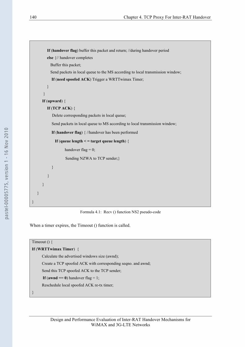
140 Chapter 4. TCP Proxy For Inter-RAT Handover
Design and Performance Evaluation of Inter-RAT Handover Mechanisms for WiMAX and 3G-LTE Networks
If (handover flag) buffer this packet and return; //during handover period
else {// handover completes
Buffer this packet;
Send packets in local queue to the MS according to local transmission window;
If (need spoofed ACK) Trigger a WRTTwimax Timer;
}
}
If (upward) {
If (TCP ACK) {
Delete corresponding packets in local queue;
Send packets in local queue to MS according to local transmission window;
If (handover flag) { //handover has been performed
If (queue length < = target queue length) {
handover flag = 0;
Sending NZWA to TCP sender;}
}
}
}
}
}
Formula 4.1: Recv () function NS2 pseudo-code
When a timer expires, the Timeout () function is called.
Timeout () {
If (WRTTwimax Timer) {
Calculate the advertised windows size (awnd);
Create a TCP spoofed ACK with corresponding seqno. and awnd;
Send this TCP spoofed ACK to the TCP sender;
If (awnd == 0) handover flag = 1;
Reschedule local spoofed ACK re-tx timer;
}
past
el-0
0005
775,
ver
sion
1 -
16 N
ov 2
010

Chapter 4. TCP Proxy For Inter-RAT Handover
Design and Performance Evaluation of Inter-RAT Handover Mechanisms for WiMAX and 3G-LTE Networks
141
If (spoofed ACK re-tx Timer) {
Calculate the awnd;
If (awnd != 0) re-send last TCP spoofed ACK;
Reschedule local spoofed ACK re-tx timer;
}
}
Formula 4.2: Timeout () function NS2 pseudo-code
4.2.4 Signaling and Primitive between IW and TCP Proxy The signaling and messages of inter-RAT handover from WiMAX to UMTS is described in Fig. 4-3.
UE/SS
Low RSSI
Source MAC (WiMax part)
MOB_SCN-REP (RSSI)
IW
Inter-RAT Handover Triggered
MOB_BSHO-REQ (Target NodeB Addr.) CMacBSHOReq
MOB_HO-INDVertical
Handover Begin
Switch Transceiver HO to UTRAN Complete
Register &Update Routers
CRrcRelocCmpInd
Normal Operation
Inter-RAT Handover, WiMAX -> UMTS , Integrated Coupling Archtecture
Link_Up trigger
CPdcpBuffInfoReqCPdcpBuffInfoCnf
CMacBSHOInd (UE Addr.)
Target RRC(UMTS part)
CRrcRelocReq
CRrcRelocCnfReserve Resource
TCP Proxy TCP Sender
ZWA
DATA
ACK DATA
ACK
NZWA (awnd)
CIWHOInd (MS addr, BDP)
DATA
WRTTwimax
CIWHOCmpInd (MS addr.)
Spoofed Ack (awnd)
A
B
C
WRTTwimax
WRTTwimax
Figure 4-3: Interaction between IW sublayer and TCP Proxy
1) After the scanning interval, the MS sends scanning report to WiMAX serving BS with
message MOB_SCN-REP, which contains physical information such as mean RSSI.
past
el-0
0005
775,
ver
sion
1 -
16 N
ov 2
010

142 Chapter 4. TCP Proxy For Inter-RAT Handover
Design and Performance Evaluation of Inter-RAT Handover Mechanisms for WiMAX and 3G-LTE Networks
2) The source WiMAX MAC sends CMacBSHOInd primitive to inform the IW sublayer of target cell id. The IW sublayer then sends CPdcpBuffInfoReq primitive to the target RRC of the UMTS network. RRC shall return the CPdcpBuffInfoCnf primitive to inform the IW sublayer of queue length and queue occupation of PDCP sublayer. According to this information, the IW sublayer adjusts its local retransmission window size.
3) The IW sublayer sends a CRrcRelocReq primitive to RRC to apply for resource allocation. The result is returned in CRrcRelocCnf primitive by RRC.
4) Upon receipt of the CRrcRelocCnf, the IW suspends sending and buffers data packets that require delivery order.
5) The IW sublayer will inform the TCP Proxy by primitive CIWHOInd. In this primitive, the MS ID and target network wireless BDP size are indicated. TCP Proxy sets target queue length and local transmission window size to this value. Upon receipt of this primitive, the TCP Proxy sends a ZWA message to TCP sender. This message freezes the TCP sender re-transmission timers and congestion window and makes TCP sender enter into persist mode.
6) The IW sublayer sends CMacBSHOReq primitive to inform source MAC that the target network is ready.
7) The MS performs handover to the BS specified in MOB_BSHO-REQ and responds with a MOB_HO-IND message.
8) MS performs normal UMTS hard handover.
9) After the MS successfully finishes UMTS radio link setup, RRC shall send the CRrcRelocCmpInd primitive to the IW sublayer, and the IW sublayer restarts data packet forwarding. Here, the primitive CRrcRelocCmpInd is defined as the Link_Up trigger.
10) The IW sublayer informs TCP Proxy of handover completion by primitive CIWHOCmpInd. Then, TCP Proxy sends the TCP segments stored in its local queue to the MS until the queue length is below the target length. After that, the TCP Proxy sends an NZWA with a calculated advertised window size to resume TCP sending.
4.2.5 Simulation Environment and Results We re-carry out the simulation in the same integrated coupling scenario as Fig. 3-10 in NS2 simulation platform. The simulation parameters are also same except for the TCP Proxy module.
4.2.5.1 Performance Comparison (a=1.5, Qt=25) In simulation of inter-RAT handover from WiMAX to UMTS, an FTP session starts at 0.4sec. A MS starts to perform handover at about 1.5sec after its entering into the coverage region of UMTS. The handover type is hard handover. At about 1.535sec, the WiMAX network entry procedure is finished and the IW sublayer on the RNC informs TCP Proxy of the handover completion. Fig. 4-4 shows the packet flows of the three kinds of handover schemes - Normal TCP, Freeze-TCP and TCP Proxy.
past
el-0
0005
775,
ver
sion
1 -
16 N
ov 2
010
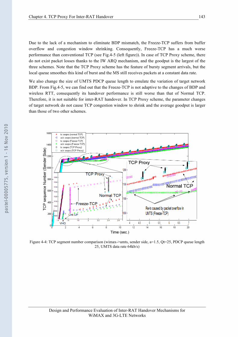
Chapter 4. TCP Proxy For Inter-RAT Handover
Design and Performance Evaluation of Inter-RAT Handover Mechanisms for WiMAX and 3G-LTE Networks
143
Due to the lack of a mechanism to eliminate BDP mismatch, the Freeze-TCP suffers from buffer overflow and congestion window shrinking. Consequently, Freeze-TCP has a much worse performance than conventional TCP (see Fig.4-5 (left figure)). In case of TCP Proxy scheme, there do not exist packet losses thanks to the IW ARQ mechanism, and the goodput is the largest of the three schemes. Note that the TCP Proxy scheme has the feature of bursty segment arrivals, but the local queue smoothes this kind of burst and the MS still receives packets at a constant data rate.
We also change the size of UMTS PDCP queue length to emulate the variation of target network BDP. From Fig.4-5, we can find out that the Freeze-TCP is not adaptive to the changes of BDP and wireless RTT, consequently its handover performance is still worse than that of Normal TCP. Therefore, it is not suitable for inter-RAT handover. In TCP Proxy scheme, the parameter changes of target network do not cause TCP congestion window to shrink and the average goodput is larger than those of two other schemes.
Figure 4-4: TCP segment number comparison (wimax->umts, sender side, a=1.5, Qt=25, PDCP queue length
25, UMTS data rate 64kb/s)
past
el-0
0005
775,
ver
sion
1 -
16 N
ov 2
010
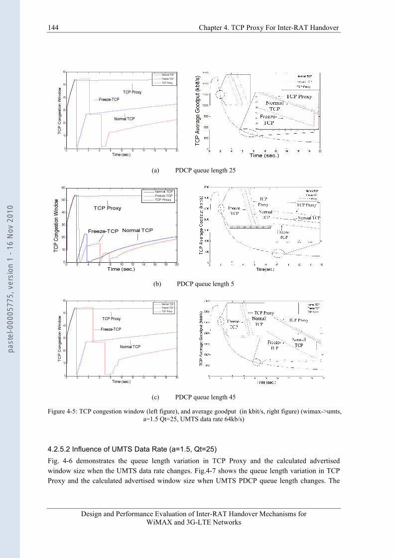
144 Chapter 4. TCP Proxy For Inter-RAT Handover
Design and Performance Evaluation of Inter-RAT Handover Mechanisms for WiMAX and 3G-LTE Networks
(a) PDCP queue length 25
(b) PDCP queue length 5
(c) PDCP queue length 45
Figure 4-5: TCP congestion window (left figure), and average goodput (in kbit/s, right figure) (wimax->umts, a=1.5 Qt=25, UMTS data rate 64kb/s)
4.2.5.2 Influence of UMTS Data Rate (a=1.5, Qt=25) Fig. 4-6 demonstrates the queue length variation in TCP Proxy and the calculated advertised window size when the UMTS data rate changes. Fig.4-7 shows the queue length variation in TCP Proxy and the calculated advertised window size when UMTS PDCP queue length changes. The
past
el-0
0005
775,
ver
sion
1 -
16 N
ov 2
010

Chapter 4. TCP Proxy For Inter-RAT Handover
Design and Performance Evaluation of Inter-RAT Handover Mechanisms for WiMAX and 3G-LTE Networks
145
changes of PDCP queue length emulate the variation of target UMTS BDP. In both figures, the queue length increases abruptly and decreases at a constant rate, which makes the queue length look like a “saw-tooth”. The interval between two advertised window “pulses” is the freeze period, during which the TCP sender is in the persist mode and its congestion window and retransmission timer are frozen. Compared with the TCP segment amount during non-freeze period, the amount of ZWA messages can be omitted. In the Fig. 4-6 (c), local queue length can reach zero during the freeze period. We call this phenomenon “under-utilization”, which can be avoided by reducing the local spoofed ACK retransmission timer period to a smaller value in terms of target network data rates and queue length. (Default value is 1.0sec in our simulation scenario.)
(a) UMTS data rate: 64kb/s (b) UMTS data rate: 128kb/s
(c) UMTS data rate: 384kb/s
Figure 4-6: The variation of local queue length and advertised window size when UMTS data rate changes (a=1.5, Qt=25, PDCP queue length 25)
past
el-0
0005
775,
ver
sion
1 -
16 N
ov 2
010
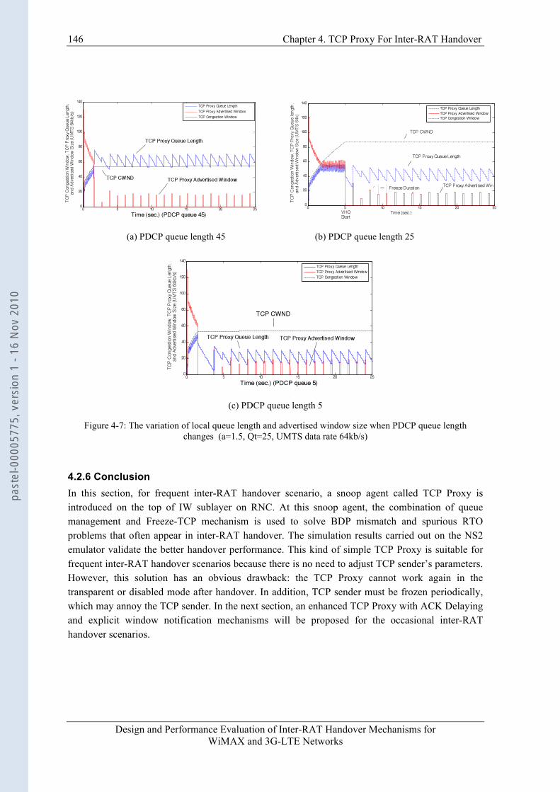
146 Chapter 4. TCP Proxy For Inter-RAT Handover
Design and Performance Evaluation of Inter-RAT Handover Mechanisms for WiMAX and 3G-LTE Networks
(a) PDCP queue length 45 (b) PDCP queue length 25
(c) PDCP queue length 5
Figure 4-7: The variation of local queue length and advertised window size when PDCP queue length changes (a=1.5, Qt=25, UMTS data rate 64kb/s)
4.2.6 Conclusion In this section, for frequent inter-RAT handover scenario, a snoop agent called TCP Proxy is introduced on the top of IW sublayer on RNC. At this snoop agent, the combination of queue management and Freeze-TCP mechanism is used to solve BDP mismatch and spurious RTO problems that often appear in inter-RAT handover. The simulation results carried out on the NS2 emulator validate the better handover performance. This kind of simple TCP Proxy is suitable for frequent inter-RAT handover scenarios because there is no need to adjust TCP sender’s parameters. However, this solution has an obvious drawback: the TCP Proxy cannot work again in the transparent or disabled mode after handover. In addition, TCP sender must be frozen periodically, which may annoy the TCP sender. In the next section, an enhanced TCP Proxy with ACK Delaying and explicit window notification mechanisms will be proposed for the occasional inter-RAT handover scenarios.
past
el-0
0005
775,
ver
sion
1 -
16 N
ov 2
010
Chapter 4. TCP Proxy For Inter-RAT Handover
Design and Performance Evaluation of Inter-RAT Handover Mechanisms for WiMAX and 3G-LTE Networks
147
4.3 Occasional Handover Scenario In this section, we describe an enhanced TCP Proxy scheme for an occasional handover scenario. In this scenario, the MS does not perform handover frequently. If the network has no ability to identify the handover scenario (frequent or occasional handover), the enhanced TCP Proxy can be applied to both long-lived and short-lived traffics by the network.
In this section, in case of no confusion, we often reuse notation “TCP Proxy” rather than “enhanced TCP Proxy” for simplicity.
4.3.1 TCP Proxy Description 1) TCP Proxy is disabled when there is no handover. When an inter-RAT handover becomes
possible due to, for example, signal strength degradation, TCP Proxy is enabled and informed of current network wireless BDP size by IW sublayer. Afterwards, the TCP Proxy works in a transparent mode.
2) In the transparent mode, a local queue is maintained for the wireless access network. This local queue maximum length is set to current access network wireless BDP size. Every incoming TCP segment is buffered in this queue and forwarded to the MS as well. When an ACK is from the MS, TCP Proxy not only forwards ACK to TCP sender, but also deletes the corresponding TCP segments from this local queue. In the transparent mode, TCP Proxy shall estimate wireless RTT (WRTT) of current network in terms of the following Jacobson RTT estimation algorithm [64], which is also implemented in conventional TCP variants.
oldWRTT (k+1) = (1-g)*oldWRTT(k) + g*WRTT(k+1) (4-2) Where g is set to 0.125; WRTT is measured wireless RTT of current network, and oldWRTT is the smoothed wireless RTT of current network before handover.
3) When a handover is forthcoming, IW sublayer sends a handover indication primitive (CIWHOInd, see below sub-clause for details) to TCP Proxy. In this primitive, the MS ID and target wireless network BDP size are indicated. Depending on the BDP size variation after handover, TCP Proxy may decide to send several triple-ACKs to TCP sender. Upon receipt of the triple ACK, TCP sender reduces congestion windows size by half and performs fast retransmission. Then, TCP Proxy sends a TCP ACK with zero receiver window size (ZWA) to the TCP sender to freeze its retransmission timer and force it to enter a persist mode [63].
4) From then on, TCP Proxy enters the handover period. In the TCP Proxy, the whole handover period is divided into three phases: Blackout phase, Draining phase and ACK Delaying phase, as shown in Fig. 4-8. In the Blackout phase, the MS performs UMTS network entry procedure and data packets cannot be received or sent. Only when TCP Proxy receives the primitive CIWHOCmpInd from IW sublayer, the Blackout phase completes, and the handover period enters into the Draining phase.
5) After handover period, TCP Proxy local queue maximum length is set to target network wireless BDP size. So, in the Draining phase, the TCP Proxy continuously forwards
past
el-0
0005
775,
ver
sion
1 -
16 N
ov 2
010
148 Chapter 4. TCP Proxy For Inter-RAT Handover
Design and Performance Evaluation of Inter-RAT Handover Mechanisms for WiMAX and 3G-LTE Networks
segments stored in the local queue to the MS. When the queue length reaches a pre-determined size 13, TCP Proxy denotes it as the end of Draining phase. During the Draining phase, TCP Proxy may estimate wireless RTT (WRTT) of target network. The estimation algorithm is similar to (4-2):
newWRTT (k+1) = (1-g)*newWRTT(k) + g*WRTT(k+1) (4-3) Where g is set to 0.125; WRTT is measured wireless RTT of target network, and newWRTT is the smoothed wireless RTT of target network.
6) As soon as the Draining phase ends, TCP Proxy fixes maximum local queue length to target network wireless BDP size. Then, TCP Proxy sends an ACK with non-zero receiver’s advertised window size (NZWA) to TCP sender to make it exit persist mode.
7) When the TCP Proxy receives a new segment from the TCP sender, a corresponding spoofed ACK timer is created locally. The timer period is set to previous wireless RTT (oldWRTT) plus an incremental change (see (4-5)). On its timeout, the TCP Proxy “spoofs” TCP sender by feeding back a locally generated TCP ACK with an advertised window size (awnd). This awnd filed is set to current free buffer size in the TCP Proxy. For notation simplicity, this spoofed ACK timer mechanism is named ACK Delaying mechanism, and this window feedback mechanism is named Explicit Window Notification (EWN).
8) When the arrival of an ACK from the TCP receiver (MS) is before the expiration of the corresponding spoofed ACK timer, it means that the RTO value of TCP sender has been adjusted to an appropriate one. Then, TCP Proxy cancels all spoofed ACK timers and the ACK Delaying phase ends. Subsequently, the EWN and ACK Delaying mechanisms are disabled, and the TCP Proxy works in a transparent mode for next possible handover, or is disabled to release buffer resource. In the transparent mode or disabled mode, it is the TCP congestion control mechanism on the sender side that controls TCP transmission rate.
9) If a new handover is forthcoming when current ACK Delaying phase is still in progress, TCP Proxy cancels all spoofed ACK timers and switches back to the transparent mode for this new handover.
In summary, firstly, triple ACK mechanism is utilized to adapt TCP congestion window size to the reduced wireless BDP size after handover. Secondly, the spoofed ACK mechanism avoids premature timeout in the TCP sender due to abrupt RTT increase after handover. Thirdly, the rate-control mechanism by feeding back “spoofed ACKs” with advertised window size prevents queue overflow during ACK Delaying phase. Fourthly, the adaptable maximum local queue length according to target network wireless BDP size avoids buffer overflow in target system. Fifthly, the fixed maximum local queue length in TCP Proxy before or after handover is based on the existence of IW sublayer. Finally, the ZWA message avoids both TCP congestion window shrinking and retransmission timer expiration in TCP sender caused by long handover blackout period.
13 In our simulation scenario, during handover period, this pre-determined size is set to half of wireless BDP size of target network to accelerate ACK Delaying procedure.
past
el-0
0005
775,
ver
sion
1 -
16 N
ov 2
010
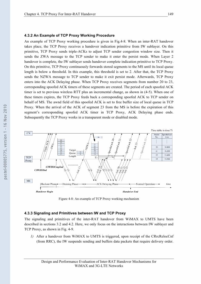
Chapter 4. TCP Proxy For Inter-RAT Handover
Design and Performance Evaluation of Inter-RAT Handover Mechanisms for WiMAX and 3G-LTE Networks
149
4.3.2 An Example of TCP Proxy Working Procedure An example of TCP Proxy working procedure is given in Fig.4-8. When an inter-RAT handover takes place, the TCP Proxy receives a handover indication primitive from IW sublayer. On this primitive, TCP Proxy sends triple-ACKs to adjust TCP sender congestion window size. Then it sends the ZWA message to the TCP sender to make it enter the persist mode. When Layer 2 handover is complete, the IW sublayer sends handover complete indication primitive to TCP Proxy. On this primitive, TCP Proxy continuously forwards stored segments to the MS until its local queue length is below a threshold. In this example, this threshold is set to 2. After that, the TCP Proxy sends the NZWA message to TCP sender to make it exit persist mode. Afterwards, TCP Proxy enters into the ACK Delaying phase. When TCP Proxy receives segments from number 20 to 23, corresponding spoofed ACK timers of these segments are created. The period of each spoofed ACK timer is set to previous wireless RTT plus an incremental change, as shown in (4-5). When one of these timers expires, the TCP Proxy feeds back a corresponding spoofed ACK to TCP sender on behalf of MS. The awnd field of this spoofed ACK is set to free buffer size of local queue in TCP Proxy. When the arrival of the ACK of segment 23 from the MS is before the expiration of this segment’s corresponding spoofed ACK timer in TCP Proxy, ACK Delaying phase ends. Subsequently the TCP Proxy works in a transparent mode or disabled mode.
Figure 4-8: An example of TCP Proxy working mechanism
4.3.3 Signaling and Primitives between IW and TCP Proxy The signaling and primitives of the inter-RAT handover from WiMAX to UMTS have been described in sections 3.2 and 4.2. Here, we only focus on the interactions between IW sublayer and TCP Proxy, as shown in Fig. 4-9.
1) After a handover from WiMAX to UMTS is triggered, upon receipt of the CRrcRelocCnf (from RRC), the IW suspends sending and buffers data packets that require delivery order.
past
el-0
0005
775,
ver
sion
1 -
16 N
ov 2
010
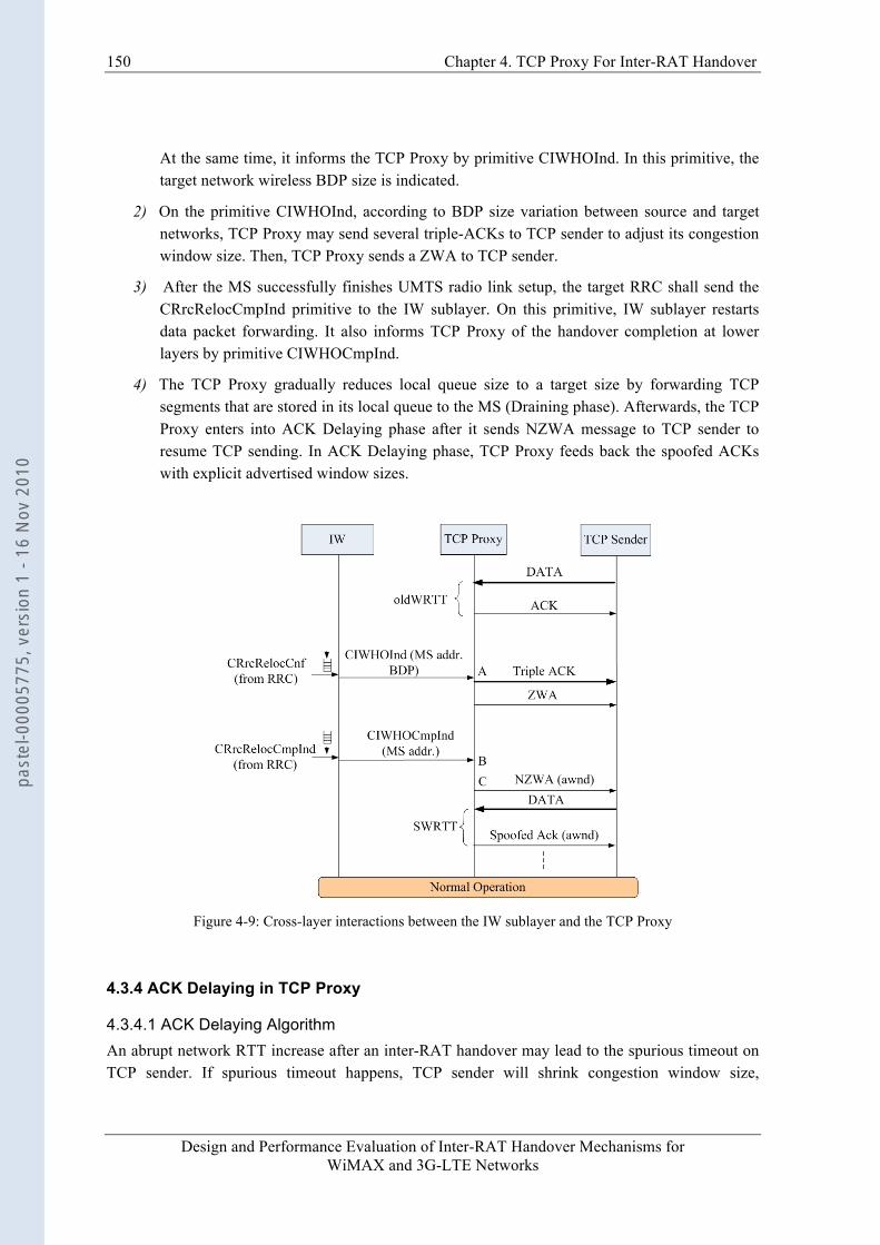
150 Chapter 4. TCP Proxy For Inter-RAT Handover
Design and Performance Evaluation of Inter-RAT Handover Mechanisms for WiMAX and 3G-LTE Networks
At the same time, it informs the TCP Proxy by primitive CIWHOInd. In this primitive, the target network wireless BDP size is indicated.
2) On the primitive CIWHOInd, according to BDP size variation between source and target networks, TCP Proxy may send several triple-ACKs to TCP sender to adjust its congestion window size. Then, TCP Proxy sends a ZWA to TCP sender.
3) After the MS successfully finishes UMTS radio link setup, the target RRC shall send the CRrcRelocCmpInd primitive to the IW sublayer. On this primitive, IW sublayer restarts data packet forwarding. It also informs TCP Proxy of the handover completion at lower layers by primitive CIWHOCmpInd.
4) The TCP Proxy gradually reduces local queue size to a target size by forwarding TCP segments that are stored in its local queue to the MS (Draining phase). Afterwards, the TCP Proxy enters into ACK Delaying phase after it sends NZWA message to TCP sender to resume TCP sending. In ACK Delaying phase, TCP Proxy feeds back the spoofed ACKs with explicit advertised window sizes.
Figure 4-9: Cross-layer interactions between the IW sublayer and the TCP Proxy
4.3.4 ACK Delaying in TCP Proxy
4.3.4.1 ACK Delaying Algorithm An abrupt network RTT increase after an inter-RAT handover may lead to the spurious timeout on TCP sender. If spurious timeout happens, TCP sender will shrink congestion window size,
past
el-0
0005
775,
ver
sion
1 -
16 N
ov 2
010
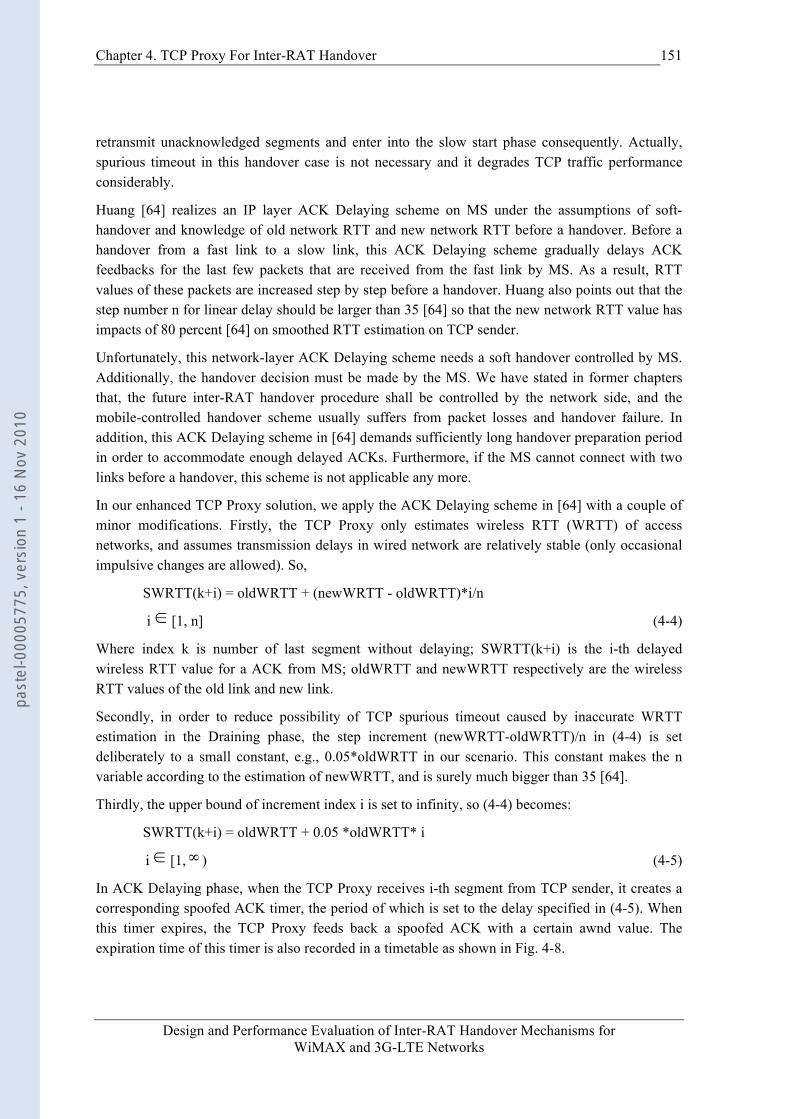
Chapter 4. TCP Proxy For Inter-RAT Handover
Design and Performance Evaluation of Inter-RAT Handover Mechanisms for WiMAX and 3G-LTE Networks
151
retransmit unacknowledged segments and enter into the slow start phase consequently. Actually, spurious timeout in this handover case is not necessary and it degrades TCP traffic performance considerably.
Huang [64] realizes an IP layer ACK Delaying scheme on MS under the assumptions of soft-handover and knowledge of old network RTT and new network RTT before a handover. Before a handover from a fast link to a slow link, this ACK Delaying scheme gradually delays ACK feedbacks for the last few packets that are received from the fast link by MS. As a result, RTT values of these packets are increased step by step before a handover. Huang also points out that the step number n for linear delay should be larger than 35 [64] so that the new network RTT value has impacts of 80 percent [64] on smoothed RTT estimation on TCP sender.
Unfortunately, this network-layer ACK Delaying scheme needs a soft handover controlled by MS. Additionally, the handover decision must be made by the MS. We have stated in former chapters that, the future inter-RAT handover procedure shall be controlled by the network side, and the mobile-controlled handover scheme usually suffers from packet losses and handover failure. In addition, this ACK Delaying scheme in [64] demands sufficiently long handover preparation period in order to accommodate enough delayed ACKs. Furthermore, if the MS cannot connect with two links before a handover, this scheme is not applicable any more.
In our enhanced TCP Proxy solution, we apply the ACK Delaying scheme in [64] with a couple of minor modifications. Firstly, the TCP Proxy only estimates wireless RTT (WRTT) of access networks, and assumes transmission delays in wired network are relatively stable (only occasional impulsive changes are allowed). So,
SWRTT(k+i) = oldWRTT + (newWRTT - oldWRTT)*i/n
i [1, n] (4-4)
Where index k is number of last segment without delaying; SWRTT(k+i) is the i-th delayed wireless RTT value for a ACK from MS; oldWRTT and newWRTT respectively are the wireless RTT values of the old link and new link.
Secondly, in order to reduce possibility of TCP spurious timeout caused by inaccurate WRTT estimation in the Draining phase, the step increment (newWRTT-oldWRTT)/n in (4-4) is set deliberately to a small constant, e.g., 0.05*oldWRTT in our scenario. This constant makes the n variable according to the estimation of newWRTT, and is surely much bigger than 35 [64].
Thirdly, the upper bound of increment index i is set to infinity, so (4-4) becomes:
SWRTT(k+i) = oldWRTT + 0.05 *oldWRTT* i
i [1, ) (4-5)
In ACK Delaying phase, when the TCP Proxy receives i-th segment from TCP sender, it creates a corresponding spoofed ACK timer, the period of which is set to the delay specified in (4-5). When this timer expires, the TCP Proxy feeds back a spoofed ACK with a certain awnd value. The expiration time of this timer is also recorded in a timetable as shown in Fig. 4-8.
past
el-0
0005
775,
ver
sion
1 -
16 N
ov 2
010

152 Chapter 4. TCP Proxy For Inter-RAT Handover
Design and Performance Evaluation of Inter-RAT Handover Mechanisms for WiMAX and 3G-LTE Networks
Upon receipt of an ACK from the MS (which is called real ACK in this section), TCP Proxy checks the timetable to confirm whether its corresponding spoofed ACK timer expiration has happened before. If so, the TCP Proxy will delete its corresponding spoofed ACK record in timetable. If not, it means the RTO of TCP sender has been adjusted to an appropriate value and the ACK Delaying mechanism can be disabled. Then, TCP Proxy works in a transparent mode or disabled mode.
4.3.4.2 Timetable Operation There is one rule to operate the timetable: upon receipt of a real ACK from MS, TCP Proxy only deletes those records in the timetable:
• the records whose corresponding spoofed ACK sequence numbers are smaller than that of this real ACK;
• the records whose corresponding spoofed ACK timers’ expiration time is smaller than arrival time of this real ACK.
When few TCP segments are lost in the wired network during ACK Delaying phase, TCP Proxy will receive out-of-order segments and re-acknowledge the last received in-order segment on behalf of MS. As a result, the timetable has several records for the same spoofed-ACK sequence number. Also, their spoofed ACK timers’ expiration time may be smaller than the arrival time of the current real ACK. In this case, to avoid any sequence number ambiguity, TCP Proxy only deletes the first one of these records in the timetable.
4.3.5 Explicit Window Notification (EWN) in TCP Proxy One objective of our scheme is to control the local queue length in TCP Proxy during an inter-RAT handover. We limit the amount of transmitted TCP packets of a connection by considering the available space of the queue in TCP Proxy on RNC. TCP Proxy modifies the awnd field in the spoofed ACKs flowing back to TCP sources. This kind of buffer management scheme has been extensively studied for years [67][68]. Although this scheme only controls the total amount of data packets injected into the target network instead of packet burst, it is still needed during a handover, because: even the local queue length of TCP Proxy can be adjusted to avoid any buffer overflow at lower sublayers during a handover, if there were no EWN in ACK Delaying phase, the TCP sender with big congestion window size might dump bursty packets to overflow the queue in TCP Proxy due to the shrunk BDP size of target network.
Since the TCP congestion window size has been adjusted to an appropriate value by triple-ACKs when handover is made, after the handover period, the EWN mechanism can be disabled.
4.3.6 Simulation Results
4.3.6.1 The Effects of EWN and ACK Delaying We re-carry out simulation in the same integrated coupling network scenario as Fig. 3-10. In the simulation of inter-RAT handover from WiMAX to UMTS, an FTP session starts at 0.4sec, and the MS starts to perform handover at about 1.5sec after its entering into the coverage region of UMTS. The handover type is hard handover. At about 1.535sec, the UMTS network entry procedure is
past
el-0
0005
775,
ver
sion
1 -
16 N
ov 2
010
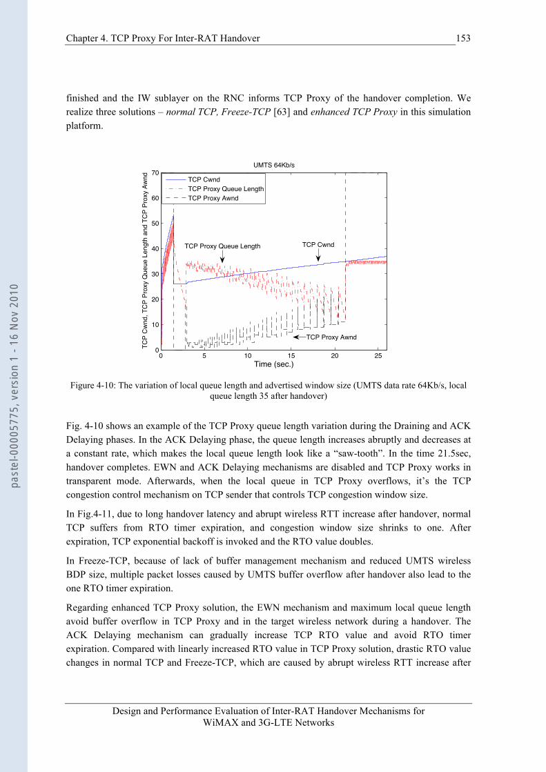
Chapter 4. TCP Proxy For Inter-RAT Handover
Design and Performance Evaluation of Inter-RAT Handover Mechanisms for WiMAX and 3G-LTE Networks
153
finished and the IW sublayer on the RNC informs TCP Proxy of the handover completion. We realize three solutions – normal TCP, Freeze-TCP [63] and enhanced TCP Proxy in this simulation platform.
0 5 10 15 20 250
10
20
30
40
50
60
70
Time (sec.)
TCP
Cw
nd, T
CP
Prox
y Q
ueue
Len
gth
and
TCP
Prox
y Aw
nd
UMTS 64Kb/s
TCP CwndTCP Proxy Queue LengthTCP Proxy Awnd
TCP CwndTCP Proxy Queue Length
TCP Proxy Awnd
Figure 4-10: The variation of local queue length and advertised window size (UMTS data rate 64Kb/s, local
queue length 35 after handover)
Fig. 4-10 shows an example of the TCP Proxy queue length variation during the Draining and ACK Delaying phases. In the ACK Delaying phase, the queue length increases abruptly and decreases at a constant rate, which makes the local queue length look like a “saw-tooth”. In the time 21.5sec, handover completes. EWN and ACK Delaying mechanisms are disabled and TCP Proxy works in transparent mode. Afterwards, when the local queue in TCP Proxy overflows, it’s the TCP congestion control mechanism on TCP sender that controls TCP congestion window size.
In Fig.4-11, due to long handover latency and abrupt wireless RTT increase after handover, normal TCP suffers from RTO timer expiration, and congestion window size shrinks to one. After expiration, TCP exponential backoff is invoked and the RTO value doubles.
In Freeze-TCP, because of lack of buffer management mechanism and reduced UMTS wireless BDP size, multiple packet losses caused by UMTS buffer overflow after handover also lead to the one RTO timer expiration.
Regarding enhanced TCP Proxy solution, the EWN mechanism and maximum local queue length avoid buffer overflow in TCP Proxy and in the target wireless network during a handover. The ACK Delaying mechanism can gradually increase TCP RTO value and avoid RTO timer expiration. Compared with linearly increased RTO value in TCP Proxy solution, drastic RTO value changes in normal TCP and Freeze-TCP, which are caused by abrupt wireless RTT increase after
past
el-0
0005
775,
ver
sion
1 -
16 N
ov 2
010
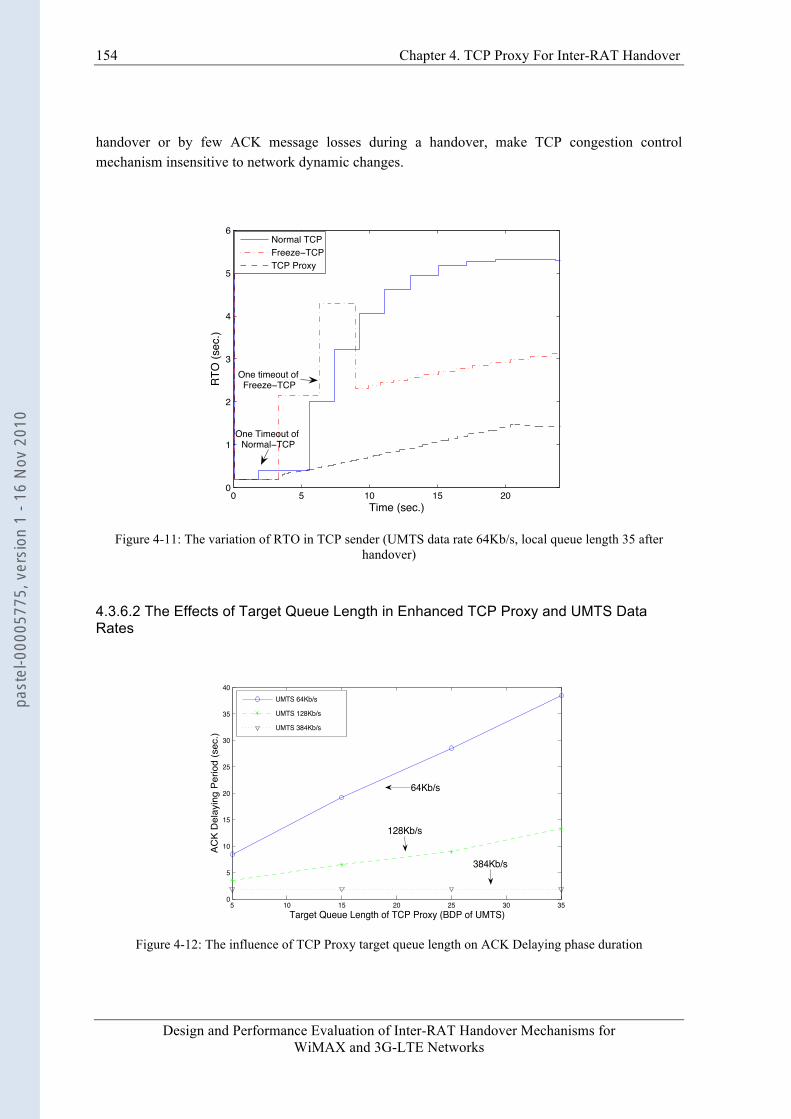
154 Chapter 4. TCP Proxy For Inter-RAT Handover
Design and Performance Evaluation of Inter-RAT Handover Mechanisms for WiMAX and 3G-LTE Networks
handover or by few ACK message losses during a handover, make TCP congestion control mechanism insensitive to network dynamic changes.
0 5 10 15 200
1
2
3
4
5
6
Time (sec.)
RTO
(sec
.)
Normal TCPFreeze TCPTCP Proxy
One timeout of Freeze TCP
One Timeout of Normal TCP
Figure 4-11: The variation of RTO in TCP sender (UMTS data rate 64Kb/s, local queue length 35 after
handover)
4.3.6.2 The Effects of Target Queue Length in Enhanced TCP Proxy and UMTS Data Rates
5 10 15 20 25 30 350
5
10
15
20
25
30
35
40
Target Queue Length of TCP Proxy (BDP of UMTS)
ACK
Del
ayin
g Pe
riod
(sec
.)
UMTS 64Kb/s
UMTS 128Kb/s
UMTS 384Kb/s
64Kb/s
128Kb/s
384Kb/s
Figure 4-12: The influence of TCP Proxy target queue length on ACK Delaying phase duration
past
el-0
0005
775,
ver
sion
1 -
16 N
ov 2
010
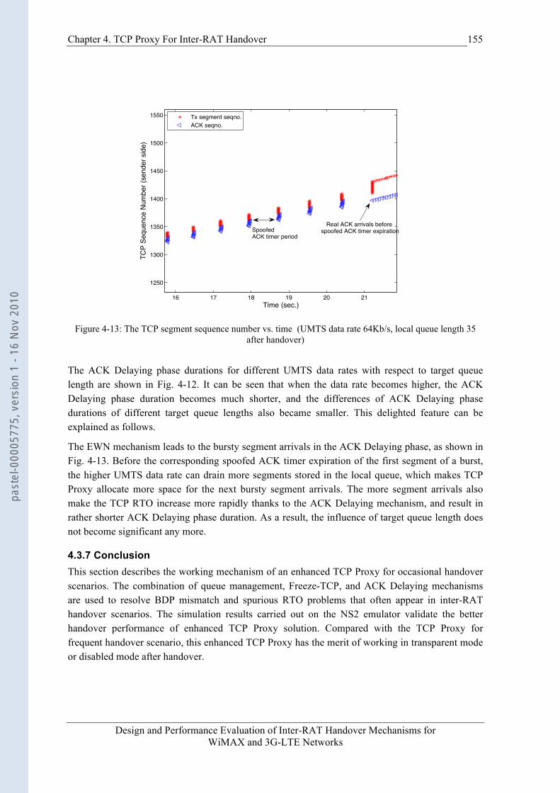
Chapter 4. TCP Proxy For Inter-RAT Handover
Design and Performance Evaluation of Inter-RAT Handover Mechanisms for WiMAX and 3G-LTE Networks
155
16 17 18 19 20 21
1250
1300
1350
1400
1450
1500
1550
Time (sec.)
TCP
Sequ
ence
Num
ber (
send
er s
ide)
Tx segment seqno.ACK seqno.
SpoofedACK timer period
Real ACK arrivals before spoofed ACK timer expiration
Figure 4-13: The TCP segment sequence number vs. time (UMTS data rate 64Kb/s, local queue length 35
after handover)
The ACK Delaying phase durations for different UMTS data rates with respect to target queue length are shown in Fig. 4-12. It can be seen that when the data rate becomes higher, the ACK Delaying phase duration becomes much shorter, and the differences of ACK Delaying phase durations of different target queue lengths also became smaller. This delighted feature can be explained as follows.
The EWN mechanism leads to the bursty segment arrivals in the ACK Delaying phase, as shown in Fig. 4-13. Before the corresponding spoofed ACK timer expiration of the first segment of a burst, the higher UMTS data rate can drain more segments stored in the local queue, which makes TCP Proxy allocate more space for the next bursty segment arrivals. The more segment arrivals also make the TCP RTO increase more rapidly thanks to the ACK Delaying mechanism, and result in rather shorter ACK Delaying phase duration. As a result, the influence of target queue length does not become significant any more.
4.3.7 Conclusion This section describes the working mechanism of an enhanced TCP Proxy for occasional handover scenarios. The combination of queue management, Freeze-TCP, and ACK Delaying mechanisms are used to resolve BDP mismatch and spurious RTO problems that often appear in inter-RAT handover scenarios. The simulation results carried out on the NS2 emulator validate the better handover performance of enhanced TCP Proxy solution. Compared with the TCP Proxy for frequent handover scenario, this enhanced TCP Proxy has the merit of working in transparent mode or disabled mode after handover.
past
el-0
0005
775,
ver
sion
1 -
16 N
ov 2
010
156 Chapter 4. TCP Proxy For Inter-RAT Handover
Design and Performance Evaluation of Inter-RAT Handover Mechanisms for WiMAX and 3G-LTE Networks
4.4 Conclusion In this chapter, we propose two kinds of snoop agents called TCP Proxies to solve the BDP mismatch and spurious RTO problems during an inter-RAT handover. The first kind of TCP Proxy is suitable for frequent handover scenarios because there are no needs to adjust TCP parameters such as RTO period or congestion window size in a TCP sender. The drawback of this kind of TCP Proxy is obvious. The TCP sender is disturbed continuously after handover by ZWA messages, which may not be acceptable to throughput-sensitive traffics such as FTP. But it is applicable for short-lived traffics such as Http.
For these reasons, for the occasional handover scenario, an enhanced TCP Proxy with ACK Delaying and EWN mechanisms is proposed. In this solution, the TCP Proxy can work in transparent mode or disabled mode after handover, which is desirable for long-lived traffics.
In the next chapter, we will consider the probability of realizing inter-RAT handover at physical layer for future LTE and WiMAX wireless access networks. We believe that if the inter-RAT handover were implemented at physical layer, a much better handover performance would be achieved in comparison with that of Layer 2 or Layer 3 solutions.
past
el-0
0005
775,
ver
sion
1 -
16 N
ov 2
010
Design and Performance Evaluation of Inter-RAT Handover Mechanisms for WiMAX and 3G-LTE Networks
Part III
Inter-RAT Handover At Layer One
past
el-0
0005
775,
ver
sion
1 -
16 N
ov 2
010
Design and Performance Evaluation of Inter-RAT Handover Mechanisms for WiMAX and 3G-LTE Networks
CHAPTER 5 INTER-RAT HANDOVER AT LAYER ONE
It is well known that the soft handover in CDMA (Code Division Multiple Access) cellular network can achieve a smooth handover procedure by keeping multiple link connections with multiple base stations. It is also desirable that there exists a soft handover management solution to achieve a seamless and smooth inter-RAT handover procedure. Unfortunately, the existing soft inter-RAT handover solutions are realized at IP or higher layers. As a result, their benefits are limited. Based on the integrated coupling architecture for 3GPP LTE (Long Term Evolution) and WiMAX, a novel interworking structure for soft inter-RAT handover at physical layer is proposed in this chapter for achieving better handover performance. Some important interworking issues, such as coupling scenario, frame structure, inter-RAT synchronization and signaling procedure are also specified. The numerical analysis shows that, even with a simple combining on the receiver side, the soft inter-RAT handover can remarkably improve the performance of outage probability in comparison with hard inter-RAT handover. Besides, the pricing mechanism in conventional congestion control is introduced into soft inter-RAT handover to further improve the handover fairness and performance.
5.1 Introduction In the former chapters, we address that one of the major aims of the inter-RAT handover management is to preserve the communication quality during a handover procedure. A handover is said to be hard inter-RAT handover when a MS always communicates with only one access network with one kind of RAT. On the other hand, a handover is said to be soft inter-RAT handover when a MS has two or more simultaneous connections with the access networks with different kinds of RATs. In CDMA system, soft handover scheme generally can prevent the connections from disruption and achieve better handover performance than hard handover. Thus, a multi-mode or multi-RAT MS is also expected to achieve satisfactory handover performance by applying a similar soft handover mechanism. Due to the independence of source and target RATs, for the moment the soft inter-RAT handover is only realized at IP layer [69], or at TCP layer [70].
In [69], in order to avoid demands of tight synchronization and cooperative scheduling between two access nodes at physical layer, the soft handover is implemented at IP layer to reduce packet error probability and power consumption by using Reed–Solomon (RS) codes. Unfortunately, this scheme only can be applicable to WIFI networks instead of the cellular networks, because the well-designed physical techniques in cellular networks, such as convolution/Turbo coding, interleaving, space-time coding, can eliminate Bit-Error-Rate (BER) to maximum extent.
past
el-0
0005
775,
ver
sion
1 -
16 N
ov 2
010
Chapter 5. Inter-RAT Handover At Layer One
Design and Performance Evaluation of Inter-RAT Handover Mechanisms for WiMAX and 3G-LTE Networks
159
In [70], there is an example of applying the SCTP to the inter-RAT handover between EGPRS/WIFI. Before a real handover takes place, the new TCP connection congestion window size is calculated based on the radio link quality of target access network. In this way, after handover, the slow start phase of standard TCP is not executed any more and the average throughput increases. However, this method is only applicable to SCTP traffics, and the link layer disruption is inevitable.
Generally speaking, the lower layer the soft inter-RAT handover is realized at, the better performance we could achieve. The existing soft inter-RAT handover schemes are all realized above Layer 2, because of the following difficulties:
• The different access networks have different physical techniques and there is no common sublayer or module at physical layer to combine data from access nodes of different RATs. This may not be the case for some future wireless access networks. In the future LTE and WiMAX systems, some common physical techniques are introduced to obtain high data rate and higher spectral efficiency. For instance, they all utilize OFDM (Orthogonal Frequency Division Multiple) modulation to eliminate frequency selectivity effect and apply space-time coding to exploit the diversity and/or capacity improvements [51][71].
• The source and target access nodes of different RATs usually locate at different places. The geographical distance makes it impossible to realize an inter-RAT handover at a common physical or MAC sublayer. But considering the fact that they can be co-located, such as in integrated coupling architecture, this is not a problem any more.
In this chapter, based on the integrated coupling scenario, we propose a novel framework to implement soft inter-RAT handover at the physical layer to improve handover performance. The better performance is validated by the outage probability comparison. A pricing mechanism is introduced to the soft inter-RAT handover to reduce average outage probability further. To our best knowledge, this proposal is the first soft inter-RAT handover physical layer scheme.
For simplicity, in this chapter, only the downlink direction and handover from LTE to WiMAX are considered. For handover from WiMAX to LTE, a similar architecture can be applied. The remainder of this chapter is organized as follows: Section 5.2 introduces the integrated coupling architecture, transmitter structures on the base stations and the receiver on a MS. Section 5.3 focuses on the implementation of synchronization mechanism. In section 5.4, outage probability calculation and a slot allocation algorithm are introduced. The concluding remarks are given in Section 5.6.
5.2 Transceiver Architecture
5.2.1 Transmitter The existing inter-RAT handover schemes are all realized above physical layer due to the geographical distance and heterogeneous radio technologies of source and target wireless networks, e.g., different modulation schemes, different access schemes and different channel coding schemes.
past
el-0
0005
775,
ver
sion
1 -
16 N
ov 2
010

160 Chapter 5. Inter-RAT Handover At Layer One
Design and Performance Evaluation of Inter-RAT Handover Mechanisms for WiMAX and 3G-LTE Networks
In case of integrated coupling architecture, the eNB (evolved NodeB) of LTE and WiMAX BS (Base Station) may locate locally in the same rack where they are connected with each other by the backboard. Even they are implemented on the same circuit board, as demonstrated in Fig. 5-1. In Fig. 5-1, the base stations consisting of eNB and WiMAX BS connects with the MME/S-GW (Mobility Management Entity/Serving GateWay) through the S1 interface. In this case, it’s better that there exists a common sublayer for smooth handover at higher layer than physical layer for these two systems, e.g., the IW sublayer in the former chapter. If the WiMAX BS directly connects with MME/S-GW, it must implement the S1 interface in its protocol stacks.
Figure 5-1: A typical integrated coupling architecture
The future LTE and WiMAX systems have some similar physical base-band technologies, such as the OFDM/OFDMA, multi-antenna transceiver and space-time coding (e.g., Alamouti coding scheme [51][71]). Based on the architecture in Fig. 5-1, it is possible that there exists a common physical module performing data block transmission and symbol combining. This common physical module is named precoder in Fig. 5-2. The precoder lies between space-time coder and IFFT. It aims at exploiting the maximal downlink cooperative diversity of heterogeneous multi-cell networks. In these heterogeneous networks, the interconnected two base station modules collaborate to server one MS. These two base station modules may be equipped with multiple antennas. The data flow from one interface (either from LTE or from WiMAX) is coded by the precoder according to current channel conditions, antenna number, subcarrier number and so on. Then, the coded data flow is transmitted through both LTE and WiMAX antennas. Hence, the soft inter-RAT handover can be realized. Compared with the soft handover in CDMA system, the proposed soft inter-RAT handover takes advantage of the cooperative diversity by simultaneously (or not simultaneously) transmitting data blocks over multiple RATs. Note that the future LTE and WiMAX may work at a same frequency band, or at different frequency bands. Both these frequent configurations will be taken into account in the following sections.
In Fig. 5-2, the RTT measurement results in the LTE wireless link and WiMAX wireless link shall be fed into the precoder to compensate the propagation delay difference of two systems. This will be covered in the section 5.3 in detail. The central controller is a common management entity that is responsible for message translation between LTE RRC/RLC/MAC and WiMAX MAC.
past
el-0
0005
775,
ver
sion
1 -
16 N
ov 2
010
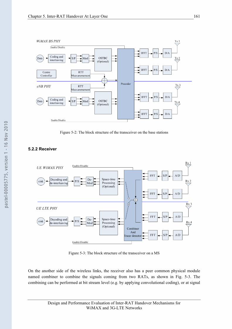
Chapter 5. Inter-RAT Handover At Layer One
Design and Performance Evaluation of Inter-RAT Handover Mechanisms for WiMAX and 3G-LTE Networks
161
Figure 5-2: The block structure of the transceiver on the base stations
5.2.2 Receiver
Figure 5-3: The block structure of the transceiver on a MS
On the another side of the wireless links, the receiver also has a peer common physical module named combiner to combine the signals coming from two RATs, as shown in Fig. 5-3. The combining can be performed at bit stream level (e.g. by applying convolutional coding), or at signal
past
el-0
0005
775,
ver
sion
1 -
16 N
ov 2
010
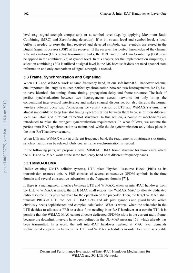
162 Chapter 5. Inter-RAT Handover At Layer One
Design and Performance Evaluation of Inter-RAT Handover Mechanisms for WiMAX and 3G-LTE Networks
level (e.g. signal strength comparison), or at symbol level (e.g. by applying Maximum Ratio Combining (MRC) and Zero-forcing detection). If at bit stream level and symbol level, a local buffer is needed to store the first received and detected symbols, e.g., symbols are stored in the Digital Signal Processor (DSP) at the receiver. If the receiver has perfect knowledge of the channel state information (CSI) of two transmission links, the MRC and Equal Gain Combining (EGC) can be applied in the combiner [72] at symbol level. In this chapter, for the implementation simplicity, a selection combining (SC) is utilized at signal level in the MS because it does not need channel state information and only comparison of signal strength is needed.
5.3 Frame, Synchronization and Signaling When LTE and WiMAX work at same frequency band, in our soft inter-RAT handover scheme, one important challenge is to keep perfect synchronization between two heterogeneous RATs, i.e., to have identical slot timing, frame timing, propagation delay and frame structure. The lack of perfect synchronization between two heterogeneous access networks not only brings the conventional inter-symbol interference and makes channel dispersive, but also disrupts the normal wireless network operation. Considering the current version of LTE and WiMAX systems, it is almost impossible to keep fine slot timing synchronization between them because of their different local oscillators and different frame/slot structures. In this section, a couple of mechanisms are introduced to relax the stringent synchronization requirements. In what follows, we assume the perfect intra-RAT synchronization is maintained, while the de-synchronization only takes place in the inter-RAT handover scenario.
When LTE and WiMAX work at different frequency band, the requirements of stringent slot timing synchronization can be relaxed. Only coarse frame synchronization is needed.
In the following parts, we propose a novel MIMO-OFDMA frame structure for those cases where the LTE and WiMAX work at the same frequency band or at different frequency bands.
5.3.1 MIMO-OFDMA Unlike existing UMTS cellular systems, LTE takes Physical Resource Block (PRB) as its transmission resource unit. A PRB consists of several consecutive OFDM symbols in the time domain and several consecutive subcarriers in the frequency domain [71].
If there is a management interface between LTE and WiMAX, when an inter-RAT handover from the LTE to WiMAX is made, the LTE MAC shall request the WiMAX MAC to allocate dedicated radio resource in its physical layer for the operation of the precoder. Then, the target WiMAX shall translate PRBs of LTE into local OFDMA slots, and add pilot symbols and guard bands, which obviously needs sophisticated and complex calculation. What is worse, when the scheduler in the LTE decides to allocate a PRB to a data flow needing inter-RAT handover at a certain TTI, it is possible that the WiMAX MAC cannot allocate dedicated OFDMA slots in the current radio frame, because the downlink intervals have been defined in the DL-MAP message [51] which already has been transmitted. In a word, the soft inter-RAT handover realized at MAC layer demands sophisticated cooperation between the LTE and WiMAX schedulers in order to ensure acceptable
past
el-0
0005
775,
ver
sion
1 -
16 N
ov 2
010
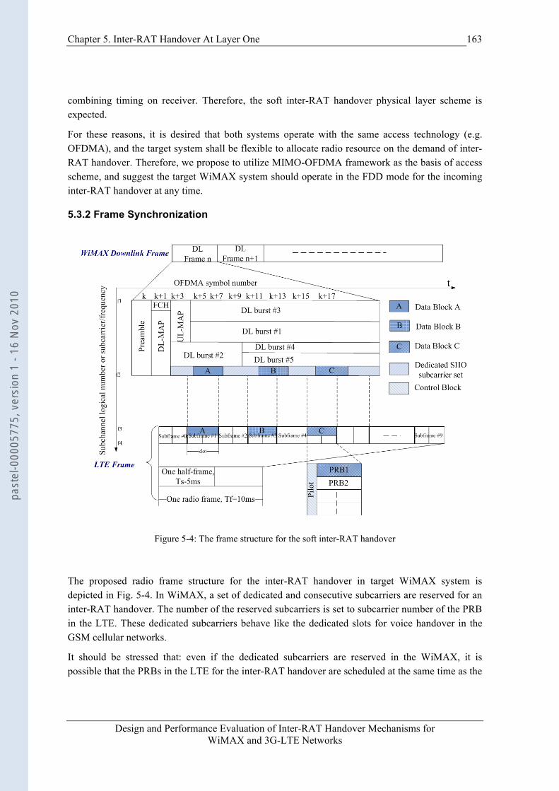
Chapter 5. Inter-RAT Handover At Layer One
Design and Performance Evaluation of Inter-RAT Handover Mechanisms for WiMAX and 3G-LTE Networks
163
combining timing on receiver. Therefore, the soft inter-RAT handover physical layer scheme is expected.
For these reasons, it is desired that both systems operate with the same access technology (e.g. OFDMA), and the target system shall be flexible to allocate radio resource on the demand of inter-RAT handover. Therefore, we propose to utilize MIMO-OFDMA framework as the basis of access scheme, and suggest the target WiMAX system should operate in the FDD mode for the incoming inter-RAT handover at any time.
5.3.2 Frame Synchronization
Figure 5-4: The frame structure for the soft inter-RAT handover
The proposed radio frame structure for the inter-RAT handover in target WiMAX system is depicted in Fig. 5-4. In WiMAX, a set of dedicated and consecutive subcarriers are reserved for an inter-RAT handover. The number of the reserved subcarriers is set to subcarrier number of the PRB in the LTE. These dedicated subcarriers behave like the dedicated slots for voice handover in the GSM cellular networks.
It should be stressed that: even if the dedicated subcarriers are reserved in the WiMAX, it is possible that the PRBs in the LTE for the inter-RAT handover are scheduled at the same time as the
past
el-0
0005
775,
ver
sion
1 -
16 N
ov 2
010

164 Chapter 5. Inter-RAT Handover At Layer One
Design and Performance Evaluation of Inter-RAT Handover Mechanisms for WiMAX and 3G-LTE Networks
WiMAX preamble and DCD/UCD/DL_MAP/UL_MAP messages are transmitted, which obviously influences the normal WiMAX operation. Therefore, the WiMAX frame timing information must be fed to LTE MAC scheduler through a management interface or through a central controller to avoid this kind of conflict. That is the reason why the frame timing information exchange between heterogeneous RATs is very important for soft inter-RAT handover.
5.3.3 Coarse Slot Synchronization Although the frame timing information can be exchanged between two heterogeneous RATs, the different propagation delays may disturb the combining in the receiver depending on the combining scheme. In order to simplify the slot synchronization among randomly distributed relay nodes, in cooperative MIMO, a diagonal radio frame structure is applied in [75]. In this diagonal radio frame structure [75], only one relay node can transmit data at a time slot and other relay nodes keep silent. So, the perfect synchronization requirement is avoided.
We also apply this coarse slot synchronization mechanism to the precoder when LTE and WiMAX work on the same frequency band. When a precoder receives a space-time code word in a PRB desiring a soft inter-RAT handover, it will map them to the next time slot in WiMAX dedicated subcarriers assuming that the repetition coding is used in the precoder. In addition, the guard intervals and differences of propagation delays between LTE and WiMAX are considered by the precoder in order to keep acceptable combining timing in the receiver. The LTE MAC scheduler shall take the responsibility of preventing multiple PRBs desiring soft handover overlapped in time axis.
When LTE and WiMAX work on different frequency bands (its often the case), the time slot alignment requirement can be relaxed. Fig. 5-4 shows the frame and slot structure when LTE and WiMAX work on different frequent bands.
Note that the deployment of soft inter-RAT handover at MAC layer becomes much easier than at physical layer when LTE and WiMAX work on different frequent bands, because no dedicated frequent bands in WiMAX are needed and slot timing requirements are relaxed. However, symbol-timing differences between WiMAX and LTE interfaces may not be satisfied due to their different MAC framing mechanisms. In this case, the benefits of soft inter-RAT handover MAC layer scheme are questionable and the physical layer scheme is preferred even when LTE and WiMAX work on different frequency bands.
We can foresee that for a seamless and smooth soft inter-RAT handover, the collaborative design of WiMAX and LTE in the future standards is desired in order to achieve fine synchronization, e.g., similar frame structure, common frame serial number, same slot size and a common management interface.
5.3.4 Signaling Procedure Generally, the soft inter-RAT handover also needs signaling exchange between two heterogeneous systems. This procedure consists of handover preparation phase and handover execution phase, as shown Fig. 5-5.
past
el-0
0005
775,
ver
sion
1 -
16 N
ov 2
010
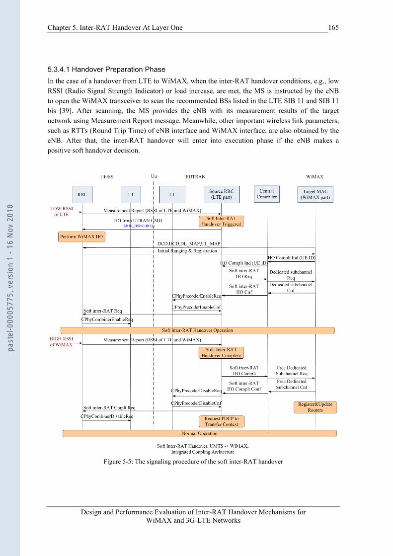
Chapter 5. Inter-RAT Handover At Layer One
Design and Performance Evaluation of Inter-RAT Handover Mechanisms for WiMAX and 3G-LTE Networks
165
5.3.4.1 Handover Preparation Phase In the case of a handover from LTE to WiMAX, when the inter-RAT handover conditions, e.g., low RSSI (Radio Signal Strength Indicator) or load increase, are met, the MS is instructed by the eNB to open the WiMAX transceiver to scan the recommended BSs listed in the LTE SIB 11 and SIB 11 bis [39]. After scanning, the MS provides the eNB with its measurement results of the target network using Measurement Report message. Meanwhile, other important wireless link parameters, such as RTTs (Round Trip Time) of eNB interface and WiMAX interface, are also obtained by the eNB. After that, the inter-RAT handover will enter into execution phase if the eNB makes a positive soft handover decision.
Figure 5-5: The signaling procedure of the soft inter-RAT handover
past
el-0
0005
775,
ver
sion
1 -
16 N
ov 2
010

166 Chapter 5. Inter-RAT Handover At Layer One
Design and Performance Evaluation of Inter-RAT Handover Mechanisms for WiMAX and 3G-LTE Networks
5.3.4.2 Handover Execution Phase 1) When the soft inter-RAT handover decision is made, the source RRC sends
HO_from_UTRAN_CMD message, which commands the MS to perform WiMAX network entry procedure. The target WiMAX BS is indicated by this message.
2) After finishing WiMAX network entry, the target WiMAX MAC sends HO_Complt_Ind message to source RRC through the Central Controller. As a consequence, the source RRC requests the target WiMAX MAC to allocated dedicated subcarriers for a soft inter-RAT handover by message Soft_inter-RAT_HO_Req.
3) The target WiMAX MAC allocates dedicated subcarriers. The confirmation message makes the source RRC to enable the precoder at the eNB physical layer by cross-layer primitive CPhyPrecoderEnableReq, and also enable the combiner in the MS.
4) When the measurement reports from the MS indicate that the signal strength of the WiMAX link is greater than a certain threshold, and the signal strength of LTE link is below a threshold (for SC combining scheme), the RRC decides to end the soft inter-RAT handover by sending message Soft_inter-RAT_HO_Complt message to the Central Controller. Then, the Central Controller requests the WiMAX MAC to take back the dedicated frequency resource.
5) The confirmation message from the Central Controller makes the source RRC disable its local precoder on eNB and the combiner on the MS.
6) The source RRC should request the PDCP layer to forward left data packets to target WiMAX system to avoid any possible packet losses if there is no IW common sublayer. If there is an IW sublayer on top of the PDCP and WiMAX MAC sublayers, the IW sublayer shall be activated before handover to ensure lossless packet delivery (refer to chapter 3 for details).
5.4 Numerical Analysis
5.4.1 System Model In this sub-clause, the effectiveness of soft inter-RAT handover is validated and Network Utility Maximization (NUM) algorithm of congestion control is applied to slot allocation. Better performance of soft inter-RAT handover is shown by outage probability comparison. The NUM resource allocation algorithm in congestion control is applied to realize slot allocation among MSs for fairness and efficiency. In the following parts, for brevity, the SC scheme is also referred to as the soft inter-RAT handover, and the non-SC (NSC) scheme is referred to as the hard inter-RAT handover.
Under the assumption of the infinite depth of the interleaving, the subcarriers after OFDM modulation are considered to be totally de-correlated. Hence, we only consider one subcarrier in this numerical analysis. Additionally, only the scenarios where LTE and WiMAX work at different frequency bands are taken into account.
past
el-0
0005
775,
ver
sion
1 -
16 N
ov 2
010
Chapter 5. Inter-RAT Handover At Layer One
Design and Performance Evaluation of Inter-RAT Handover Mechanisms for WiMAX and 3G-LTE Networks
167
We use a simple channel model in [91], where both channel coefficients and noises are assumed to be Gaussian random variables. In LTE (WiMAX) network, interferences are from many other distant LTE (WiMAX) cells, and can also be assumed to be a Gaussian random variable in this section. We first define the following symbols and assumptions. The subscripts “e, i” and “w, j” of these symbols represent the “LTE i-th subcarrier” and “WiMAX j-th subcarrier” respectively.
, : channel coefficients (
€
CN(0,σe,i2 ) and
€
CN(0,σw, j2 ) distributions respectively)
€
ne,i ,
€
nw, j : received interferences (
€
CN(0,Noe ) and
€
CN(0,Now ) distributions respectively).
€
γ e,i ,
€
γw, j : SINRs (Signal to Interference plus Noise Ratio) on the receiver side.
P: power allocation to LTE or WiMAX transmitters.
Under these assumptions, and
€
γw, j = hw, j2P /No
w . Obviously, they are exponentially distributed [91]. So, probability density function of and are written as:
(5-1)
In this section, the probability that the combined signal ( ) on MS is below a threshold is referred to as outage probability for our SC scheme in the combiner. We consider the repetition coding, namely symbols sent over LTE and WiMAX transmitters are same. Because
and are SINRs at different LTE and WiMAX subcarriers, they are independent of each other. Therefore, the outage probability for SC scheme is the probability that both and are below the given threshold , as expressed by:
(5-2)
The outage probability for non-SC scheme is given by
(5-3)
Similarly, if a MS has
€
xi slots to perform selection combining, then outage probability is
€
PoutSC = [1− exp(−γ o /γ e,i)]*[1− exp(−γ o /γw, j )]
xi (5-4)
From comparison among (5-2), (5-3) and (5-4), it can be seen that the SC scheme outperforms non-SC scheme, especially at medium and high SINRs. This confirms our idea that soft inter-RAT handover can achieve better performance than the hard one even a simple SC scheme is applied.
Then a natural question arises - how to allocate slot resource among MSs. We apply the NUM resource allocation algorithm in congestion control to solve this problem.
5.4.2 Slot Allocation The data traffics of a MS desire as many slots as possible in handover target system to achieve a relatively low symbol error rate or low outage probability. We assume that these MSs are independent and behave in a selfish and rational. In addition, even though the base station configures the MS in a combining mode and the MS reports SINR honestly, the MS may have
€
PoutNSC = 1− exp(−γ o /γ e, i )€
PoutSC = [1− exp(−γ o /γ e, i )]* [1− exp(−γ o /γw, j )]
past
el-0
0005
775,
ver
sion
1 -
16 N
ov 2
010
168 Chapter 5. Inter-RAT Handover At Layer One
Design and Performance Evaluation of Inter-RAT Handover Mechanisms for WiMAX and 3G-LTE Networks
several combining choices, such as SC, MRC, EGC, RS coding… So, a same slot resource in a WiMAX dedicated frequency channel leads to distinguish combining performance in MSs, which is unpredictable to the network. On the network side, the network wishes to optimize a certain overall handover metric for all MSs, not for an individual MS. Hence, when the number of traffics or MSs demanding soft handover increases, the competition among them becomes a game problem and there shall exist a mechanism on network side for allocating slot resources efficiently and fairly.
The limited bandwidth resource allocation problem has been extensively studied in previous efforts [76][77][78], where this problem is named Network Utility Maximization (NUM). In these works, overall system optimization problem is decomposed into two sub-problems: One is for users and another is for network. The key point of this decomposition is that Lagrange multiplier is used as bandwidth price factor, which can regulate users’ bandwidth demands.
Our slot allocation can be considered as a special case of this network bandwidth allocation problem, where there is only one link and the slot resource is a kind of special bandwidth. To simplify the problem, we relax the integer constraint of slot number, and allow it to be changeable between zero and maximal slot number. In this section, we interchangeably use terms the “MS” and the “user”. For brevity, the NUM resource allocation algorithm is also referred to as pricing mechanism in this section.
Basic Algorithm Based on NUM problem [76][77][78], our slot allocation is described by:
Maximize
€
Uii∑ (xi)
Subject to
€
xii∑ ≤ C
€
xi ∈ [0,C]
€
∀i ∈ N (5-5)
Where the
€
Ui(xi) is MS’s utility function when it obtain
€
xi slots. Assume that the utility
€
Ui(xi) is an increasing, strictly concave and continuously differentiable function with respect to
€
xi over the range
€
xi ∈ [0,C]. The C is the maximal slot number that the target network has for the soft inter-RAT handover. N is the total number of MS demanding handover.
Keep in mind the slot allocation problem is based on the assumption that the network does not know the MS’s utility. Otherwise, the network can apply convex analysis to get a global optimal slot allocation solution.
S.H. Low [77] proposes two iteration algorithms respectively at user level and network level, as shown in (5-6) and (5-7), in order to solve those problems like (5-5). At the user level, each MS i needs to optimize the following utility function [77] for the given slot price
€
λ :
Maximize
€
∀i ∈ N (5-6)
At the network level, the network calculates the next slot price by gradient method [77] shown as follows:
€
λ(t +1) = [λ(t) −α(C − xi*(λ(t))
i∑ )]+ (5-7) €
xi*(λ) = argmax[
xi
Ui(xi )− λxi ]
past
el-0
0005
775,
ver
sion
1 -
16 N
ov 2
010
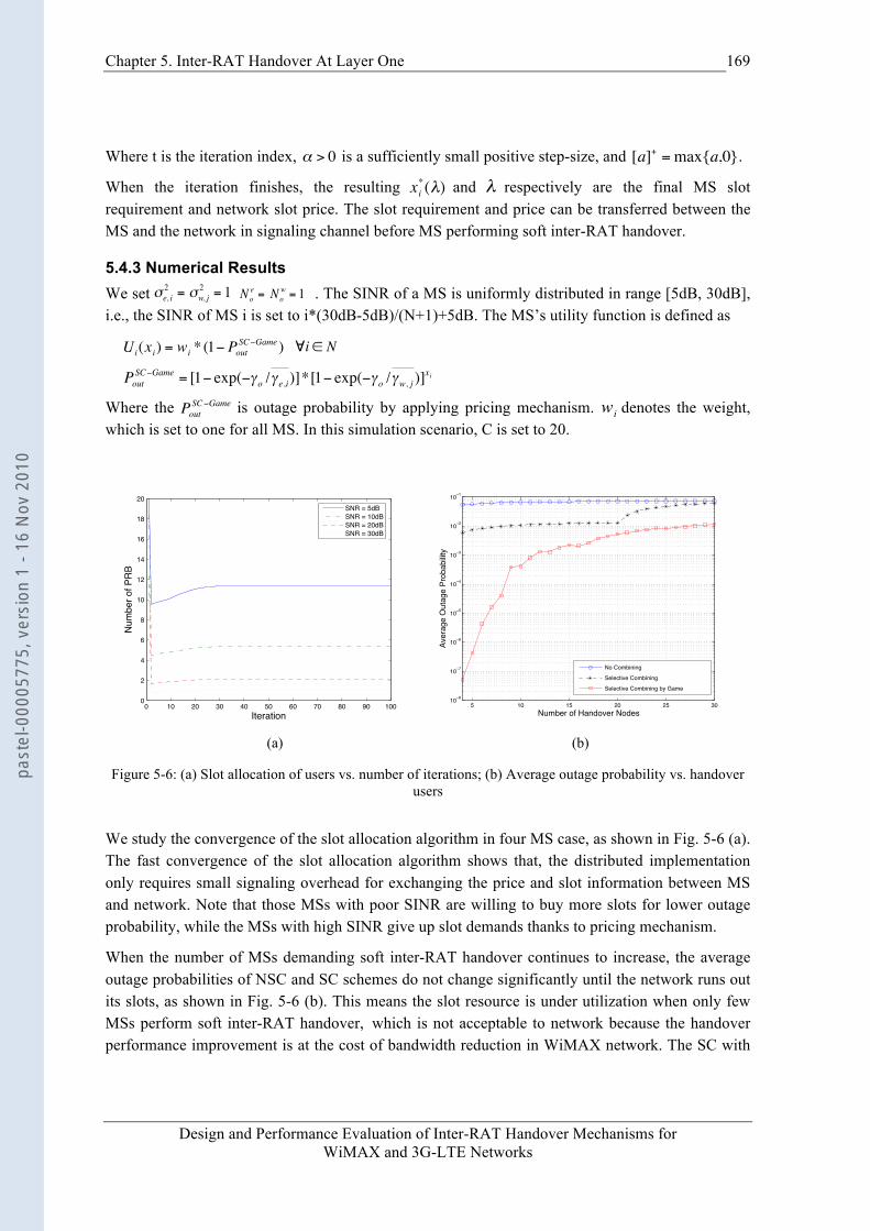
Chapter 5. Inter-RAT Handover At Layer One
Design and Performance Evaluation of Inter-RAT Handover Mechanisms for WiMAX and 3G-LTE Networks
169
Where t is the iteration index,
€
α > 0 is a sufficiently small positive step-size, and
€
[a]+ =max{a,0}.
When the iteration finishes, the resulting
€
xi*(λ) and
€
λ respectively are the final MS slot requirement and network slot price. The slot requirement and price can be transferred between the MS and the network in signaling channel before MS performing soft inter-RAT handover.
5.4.3 Numerical Results We set . The SINR of a MS is uniformly distributed in range [5dB, 30dB], i.e., the SINR of MS i is set to i*(30dB-5dB)/(N+1)+5dB. The MS’s utility function is defined as
€
Ui(xi) = wi * (1− PoutSC−Game )
€
∀i ∈ N
€
PoutSC−Game = [1− exp(−γ o /γ e,i)]*[1− exp(−γ o /γw, j )]
xi
Where the
€
PoutSC−Game is outage probability by applying pricing mechanism.
€
wi denotes the weight, which is set to one for all MS. In this simulation scenario, C is set to 20.
0 10 20 30 40 50 60 70 80 90 1000
2
4
6
8
10
12
14
16
18
20
Iteration
Num
ber o
f PR
B
SNR = 5dBSNR = 10dBSNR = 20dBSNR = 30dB
5 10 15 20 25 3010 8
10 7
10 6
10 5
10 4
10 3
10 2
10 1
Number of Handover Nodes
Aver
age
Out
age
Prob
abilit
y
No CombiningSelective CombiningSelective Combining by Game
(a) (b)
Figure 5-6: (a) Slot allocation of users vs. number of iterations; (b) Average outage probability vs. handover users
We study the convergence of the slot allocation algorithm in four MS case, as shown in Fig. 5-6 (a). The fast convergence of the slot allocation algorithm shows that, the distributed implementation only requires small signaling overhead for exchanging the price and slot information between MS and network. Note that those MSs with poor SINR are willing to buy more slots for lower outage probability, while the MSs with high SINR give up slot demands thanks to pricing mechanism.
When the number of MSs demanding soft inter-RAT handover continues to increase, the average outage probabilities of NSC and SC schemes do not change significantly until the network runs out its slots, as shown in Fig. 5-6 (b). This means the slot resource is under utilization when only few MSs perform soft inter-RAT handover, which is not acceptable to network because the handover performance improvement is at the cost of bandwidth reduction in WiMAX network. The SC with
€
Noe = No
w = 1
€
σe, i2 = σw, j
2 = 1
past
el-0
0005
775,
ver
sion
1 -
16 N
ov 2
010
170 Chapter 5. Inter-RAT Handover At Layer One
Design and Performance Evaluation of Inter-RAT Handover Mechanisms for WiMAX and 3G-LTE Networks
game can efficiently utilize slot resource when there are few MSs demanding soft inter-RAT handover. So the average outage probability is rather low compared to other two schemes. When the MS number increases, those MSs with good channel conditions begin to gradually give up slots for the MSs with poor channel conditions thanks to the pricing mechanism. The slots are fairly allocated among these MSs. Therefore, the SC with game scheme always achieves lower average outage probability than other two schemes.
5.5 Conclusion In this chapter, a novel soft inter-RAT handover physical layer scheme is proposed on the basis of integrated coupling architecture for future LTE and WiMAX systems. To implement this novel soft inter-RAT handover scheme, some interworking structures are also specified, such as frame structure, inter-RAT synchronization and signaling procedure. The numerical analysis shows that even with a simply combining on the receiver side, the soft inter-RAT handover can remarkably reduce the outage probability in comparison with the hard one. Besides, the pricing mechanism in congestion control domain is applied to soft inter-RAT handover to further improve the slot allocation fairness and efficiency.
past
el-0
0005
775,
ver
sion
1 -
16 N
ov 2
010
Design and Performance Evaluation of Inter-RAT Handover Mechanisms for WiMAX and 3G-LTE Networks
CHAPTER 6 CONCLUSION
To conclude this thesis, this finial chapter will review our major research results through a summary of the main contributions, and then will indicate some future research directions.
6.1 Contributions The future beyond third generation (B3G) or fourth generation (4G) systems will coexist with different radio access technologies, such as GSM/GPRS, UMTS, WIFI, and WiMAX. The interworking of these radio access networks becomes necessary for providing better seamless mobility service for the mobile users. According to mobility service requirements, there exist many technical problems or implementation issues. Different mobility service requirements also lead to different implementation solutions. Hence, it is better to identify these technical problems or implementation issues before proposing a convergence solution for heterogeneous wireless networks.
Two key implementation issues are the inter-RAT handover solution and the interworking architecture. In our research project on convergence of future mobile networks, we take these issues into account for interconnecting UMTS network with WiMAX network. The objective of this project is to provide a seamless and smooth handover solution for mobile users roaming between these two systems.
Generally, in order to realize a seamless inter-RAT handover among heterogeneous networks in a certain interworking architecture, source networks and target networks should have something in common, such as common handover signaling flow, common control messages, common protocol functions and common network entities. Since all future mobile networks are based on IP technologies, realizing handover at IP layer becomes a natural choice. We start with the investigation of Mobile IP and its extensions, especially the FMIPv6 [4][5]. The FMIPv6 has shorter handover blackout and lower packet loss than Mobile IP [1] thanks to its buffering-and-forwarding mechanism and NCoA validation prior to a handover. So, FMIPv6 is considered as a promising future inter-RAT handover solution. However, the weaknesses of FMIPv6, as shown in analysis and simulation results, make us turn to a handover solution at a lower layer, e.g., at Layer 2. The mature 3GPP inter-RAT handover instructs us to design a common sublayer at Layer 2 for UMTS and WiMAX to resolve some typical handover problems - packet losses and long handover latency. This common sublayer, which is called IW sublayer, has the feature of inter-system retransmission mechanism. For TCP traffics, only an inter-system retransmission mechanism at IW sublayer is not sufficient because TCP traffics are subject to other specific problems, such as BDP
past
el-0
0005
775,
ver
sion
1 -
16 N
ov 2
010
172 Chapter 6. Conclusion
Design and Performance Evaluation of Inter-RAT Handover Mechanisms for WiMAX and 3G-LTE Networks
mismatch and spurious RTO. We design a snoop agent named TCP Proxy on the RNC in the integrated architecture to smooth the sudden parameter changes of access networks after handover. Eventually, in the integrated coupling architecture, we exploit the possibility of a kind of soft-handover physical layer scheme to obtain a better handover procedure, i.e., high SINR during a handover. The new precoder and combiner for handover locate at base station (BS) and mobile station (MS) respectively.
In what follows, we list our main contributions in detail.
6.1.1 FMIPv6 Timing Analysis In the second chapter, we investigate the working mechanism and the handover performance of Mobile IP and its extensions. The measurement and simulation results show that the long handover latency and high packet losses of Mobile IP are not suitable for delay-sensitive and throughput-sensitive traffics. As one noticeable extension, FMIPv6 is considered as a promising vertical handover solution for future heterogeneous mobile networks thanks to its fast movement detection, fast binding update and context transfer mechanisms. Therefore, it is necessary to investigate this specific solution in order to make sure that whether it can fulfill high-QoS handover requirements.
We follow the timing diagram methodology in [26] to analyze the FMIPv6 handover performance under the assumption of perfect lower layers, i.e., no packets/frames stored at MAC/PHY layers during a handover, and there are a couple of cross-layer triggers between the IP layer and link layer. We identify the conditions in which the best handover performance can be achieved, and indicate the limitations when the FMIPv6 is used as the inter-RAT handover management.
The analysis and simulation results show that the FMIPv6 is not suitable for both delay-sensitive and throughput-sensitive traffics. The reasons are mainly as follows. Firstly, the MS is allowed to make the handover decision and control the handover procedure. Secondly, buffering-and-forwarding context transfer scheme in FMIPv6 is not enough for a lossless handover procedure.
These analytical results will guide us in the design of Layer 2 inter-RAT handover solution.
6.1.2 IW Sublayer in Integrated Coupling and Tight Coupling Architectures Based on the analysis of FMIPv6, we propose a novel Layer 2 inter-RAT handover solution by introducing a new common sublayer named IW sublayer and an inter-system retransmission mechanism (IW ARQ) to resolve the packet loss and long handover latency problems in the integrated and tight coupling architectures.
In tight coupling architecture, compared with the buffering-and-forwarding context transfer scheme in FMIPv6, the IW ARQ scheme has the merits of shorter handover latency and zero packet loss, as shown in the network simulation results. The simulation also demonstrates that the packets lost at lower layers during a handover, which are often omitted in the FMIPv6 analysis, degrade FMIPv6 performance significantly.
In integrated coupling architecture, we also compare the IW ARQ handover performance with that of other context transfer schemes such as SDU Reconstruction [57] and R-LLC [56]. The simulation results show their limitations the advantages of the IW ARQ scheme.
past
el-0
0005
775,
ver
sion
1 -
16 N
ov 2
010

Chapter 6. Conclusion
Design and Performance Evaluation of Inter-RAT Handover Mechanisms for WiMAX and 3G-LTE Networks
173
6.1.3 TCP Proxy for Frequent and Occasional Handover Scenarios Although the IW sublayer solves packet loss and long handover latency problems, for TCP traffics, there are some other specific handover problems, BDP mismatch, spurious RTO, false retransmission and so on. So, two kinds of snoop agents called TCP Proxies, which interact with the IW sublayer, are also introduced on RNC to solve two inter-RAT handover problems: BDP mismatch and spurious RTO. The first kind of TCP Proxy is applicable to frequent handover scenarios (e.g., a MS moves back and forth in a cell boundary). On the contrary, the second kind of TCP Proxy is applicable to occasional handover scenarios regardless of the long-lived or short-lived traffic. Compared with other vertical handover solutions, our novel inter-RAT solution with cross-layer mechanism has the merit of keeping existing TCP protocol stacks unchanged.
6.1.4 Soft Inter-RAT handover at Physical Layer Generally speaking, the lower layer the handover solution is realized at, the better handover performance we could achieve. All the conventional inter-RAT handover solutions are realized at Layer 2 or above due to the impossibility of common module at physical layer. But for the future LTE and WiMAX systems, this is not the case, because they have some common physical technologies such as MIMO and OFDM. In the integrated coupling architecture, two common modules named precoder and combiner are proposed respectively on BS and on MS at physical layer to exploit the maximum diversity of two RATs. Some important interworking structures, such as coupling scenario, frame structure, inter-RAT synchronization and signaling procedure are also re-designed. This soft inter-RAT handover physical layer scheme is totally new to the best of our knowledge.
6.2 Perspectives
6.2.1 Physical Layer Soft Inter-RAT Handover Performance Evaluation Although we design a novel soft inter-RAT handover physical layer scheme, the evaluation remains a critical issue before its application. We will develop an LTE-similar and WiMAX simulation platform to verify the effectiveness of the novel solution. This simulation should have the following features: OFDMA-based, multiple antennas on BS and MS, similar data block size in LTE and WiMAX.
For the moment, we only consider the selection combining in the receiver. But if the perfect channel state information is available to receiver (CSIR) and transmitter (CSIT), the combination of eigen-beamforming and space-time coding can achieve better handover performance than selection combining [83]. Whether we adapt the conventional space-time coding to our diagonal transmission slot architecture, or design a new space-time coding scheme becomes an open problem.
6.2.2 Retransmission Mechanism at IP layer We have proposed a novel IW sublayer and retransmission mechanism to resolve typical inter-RAT handover problems for UMTS-WiMAX interworking. This kind of solution also can be applied to multiple interworking scenarios, such as UMTS-WIFI, GPRS-WIFI and GPRS-WiMAX. For WIFI-WiMAX interworking, or interworking between WiMAX with other 802-based networks,
past
el-0
0005
775,
ver
sion
1 -
16 N
ov 2
010
174 Chapter 6. Conclusion
Design and Performance Evaluation of Inter-RAT Handover Mechanisms for WiMAX and 3G-LTE Networks
adding a novel IW sublayer is not very necessary any more because IP layer is their common layer. Hence we could add inter-system retransmission mechanism to IP-based mobility solutions such as MIPv6 and FMIPv6. However, unlike retransmission mechanism at IW sublayer, simple adding retransmission mechanism to IP sublayer does not necessarily bring better handover performance, for the following reasons:
• One WIFI access point (AP) or WiMAX BS may connect with different access routers (ARs), which means the ACK messages of retransmission mechanism at IP layer may be fed back by MS to different ARs because IP layer terminates at AR, not AP. Therefore, implementing retransmission mechanism at IP layer demands particular access network architectures, e.g., every AR in mobility domains must support retransmission mechanism and context transfer scheme.
• An AR may serve a huge population of MSs but the buffer resource is limited. A tradeoff must be made between mobility serving domain size and the cost of ARs.
• Retransmission mechanism must be realized on both transmitter side and receiver side. This means the IP stacks on MS side should also be modified.
For these reasons, we must make the following assumption:
• Every AR must support retransmission and context transfer mechanisms. Prior to a handover, the source AR shall forward context related parameters, unsent data packets and blocks to the target AR. During a handover, they shall exchange the ACKs received from MS. (Only downlink is considered.)
For example, we consider the case where the retransmission and context transfer mechanisms are applied to FIMPv6. When a PAR receives a FBU message from a MS that demands predictive mode fast handover, the PAR initiates the local retransmission function as well as the retransmission function on the MS by message FBack. After that, every incoming packet destined for the MS will be fragmented (if necessary) and attached a sub-header. This sub-header with packet sequence number is used by AR and MS to ensure in-order packet delivery. Another possible solution is to use option fields in IP packet header as the sub-header and retransmission tag. When the MS receives a packet with retransmission tag, it shall feed back a special ACK packet with retransmission tag. On receipt of this special ACK packet, PAR deletes the corresponding data packet in its local buffer.
When the PAR receives Hack message from NAR, the unacknowledged packets stored in PAR are forwarded to the NAR. The NAR will retransmit these packets demanding in-order delivery to MS on behalf of PAR upon receipt of message FNA. Every ACK packet received by PAR or NAR is exchanged between them.
Keep in mind that the retransmission mechanism should be realized on both AR and MS sides. A network simulation platform shall be built to check the flexibility and performance of this IP layer retransmission mechanism, and find its advantages and disadvantages.
past
el-0
0005
775,
ver
sion
1 -
16 N
ov 2
010
Chapter 6. Conclusion
Design and Performance Evaluation of Inter-RAT Handover Mechanisms for WiMAX and 3G-LTE Networks
175
6.2.3 Multihoming at Layer Two Since a multi-RAT MS has several radio interfaces, it may have the ability to simultaneously connect with networks through interfaces of different RATs during a handover in order to improve handover performance. Generally, this ability is referred to as “Multihoming”. With the multihoming ability, a MS can use just one interface or all interfaces simultaneously for achieving a seamless and smooth handover.
Based on our IW sublayer framework, we will develop a multihoming scheme at Layer 2 in the tight and integrated coupling architectures to realize a seamless mobility between UMTS and WiMAX networks. This novel Layer 2 multihoming scheme can enable soft handover and make-before-break handover, which are lossless and have shorter latency than the Layer 2 hard handover.
past
el-0
0005
775,
ver
sion
1 -
16 N
ov 2
010
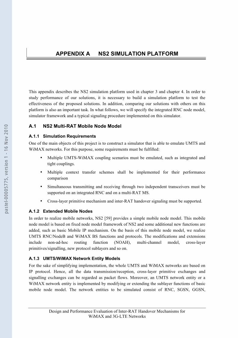
Design and Performance Evaluation of Inter-RAT Handover Mechanisms for WiMAX and 3G-LTE Networks
APPENDIX A NS2 SIMULATION PLATFORM
This appendix describes the NS2 simulation platform used in chapter 3 and chapter 4. In order to study performance of our solutions, it is necessary to build a simulation platform to test the effectiveness of the proposed solutions. In addition, comparing our solutions with others on this platform is also an important task. In what follows, we will specify the integrated RNC node model, simulator framework and a typical signaling procedure implemented on this simulator.
A.1 NS2 Multi-RAT Mobile Node Model
A.1.1 Simulation Requirements One of the main objects of this project is to construct a simulator that is able to emulate UMTS and WiMAX networks. For this purpose, some requirements must be fulfilled:
• Multiple UMTS-WiMAX coupling scenarios must be emulated, such as integrated and tight couplings.
• Multiple context transfer schemes shall be implemented for their performance comparison
• Simultaneous transmitting and receiving through two independent transceivers must be supported on an integrated RNC and on a multi-RAT MS.
• Cross-layer primitive mechanism and inter-RAT handover signaling must be supported.
A.1.2 Extended Mobile Nodes In order to realize mobile networks, NS2 [59] provides a simple mobile node model. This mobile node model is based on fixed node model framework of NS2 and some additional new functions are added, such as basic Mobile IP mechanism. On the basis of this mobile node model, we realize UMTS RNC/NodeB and WiMAX BS functions and protocols. The modifications and extensions include non-ad-hoc routing function (NOAH), multi-channel model, cross-layer primitives/signalling, new protocol sublayers and so on.
A.1.3 UMTS/WiMAX Network Entity Models For the sake of simplifying implementation, the whole UMTS and WiMAX networks are based on IP protocol. Hence, all the data transmission/reception, cross-layer primitive exchanges and signalling exchanges can be regarded as packet flows. Moreover, an UMTS network entity or a WiMAX network entity is implemented by modifying or extending the sublayer functions of basic mobile node model. The network entities to be simulated consist of RNC, SGSN, GGSN,
past
el-0
0005
775,
ver
sion
1 -
16 N
ov 2
010
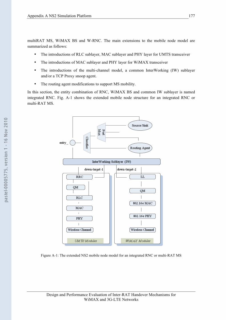
Appendix A NS2 Simulation Platform
Design and Performance Evaluation of Inter-RAT Handover Mechanisms for WiMAX and 3G-LTE Networks
177
multiRAT MS, WiMAX BS and W-RNC. The main extensions to the mobile node model are summarized as follows:
• The introductions of RLC sublayer, MAC sublayer and PHY layer for UMTS transceiver
• The introductions of MAC sublayer and PHY layer for WiMAX transceiver
• The introductions of the multi-channel model, a common InterWorking (IW) sublayer and/or a TCP Proxy snoop agent.
• The routing agent modifications to support MS mobility.
In this section, the entity combination of RNC, WiMAX BS and common IW sublayer is named integrated RNC. Fig. A-1 shows the extended mobile node structure for an integrated RNC or multi-RAT MS.
Figure A-1: The extended NS2 mobile node model for an integrated RNC or multi-RAT MS
past
el-0
0005
775,
ver
sion
1 -
16 N
ov 2
010
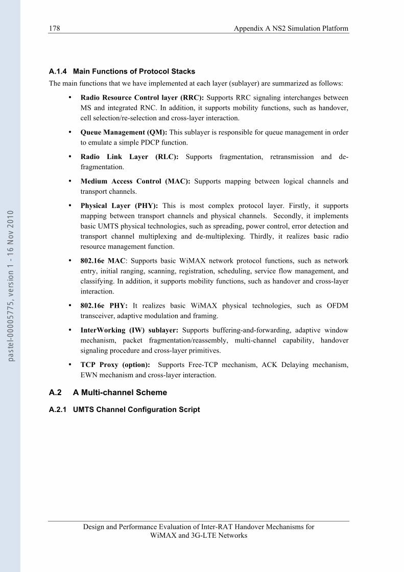
178 Appendix A NS2 Simulation Platform
Design and Performance Evaluation of Inter-RAT Handover Mechanisms for WiMAX and 3G-LTE Networks
A.1.4 Main Functions of Protocol Stacks The main functions that we have implemented at each layer (sublayer) are summarized as follows:
• Radio Resource Control layer (RRC): Supports RRC signaling interchanges between MS and integrated RNC. In addition, it supports mobility functions, such as handover, cell selection/re-selection and cross-layer interaction.
• Queue Management (QM): This sublayer is responsible for queue management in order to emulate a simple PDCP function.
• Radio Link Layer (RLC): Supports fragmentation, retransmission and de-fragmentation.
• Medium Access Control (MAC): Supports mapping between logical channels and transport channels.
• Physical Layer (PHY): This is most complex protocol layer. Firstly, it supports mapping between transport channels and physical channels. Secondly, it implements basic UMTS physical technologies, such as spreading, power control, error detection and transport channel multiplexing and de-multiplexing. Thirdly, it realizes basic radio resource management function.
• 802.16e MAC: Supports basic WiMAX network protocol functions, such as network entry, initial ranging, scanning, registration, scheduling, service flow management, and classifying. In addition, it supports mobility functions, such as handover and cross-layer interaction.
• 802.16e PHY: It realizes basic WiMAX physical technologies, such as OFDM transceiver, adaptive modulation and framing.
• InterWorking (IW) sublayer: Supports buffering-and-forwarding, adaptive window mechanism, packet fragmentation/reassembly, multi-channel capability, handover signaling procedure and cross-layer primitives.
• TCP Proxy (option): Supports Free-TCP mechanism, ACK Delaying mechanism, EWN mechanism and cross-layer interaction.
A.2 A Multi-channel Scheme
A.2.1 UMTS Channel Configuration Script
past
el-0
0005
775,
ver
sion
1 -
16 N
ov 2
010
Appendix A NS2 Simulation Platform
Design and Performance Evaluation of Inter-RAT Handover Mechanisms for WiMAX and 3G-LTE Networks
179
Figure A-2: Configuration of UMTS channel
A.2.2 WiMAX Channel Configuration Script
Figure A-3: Configuration of WiMAX channel
past
el-0
0005
775,
ver
sion
1 -
16 N
ov 2
010
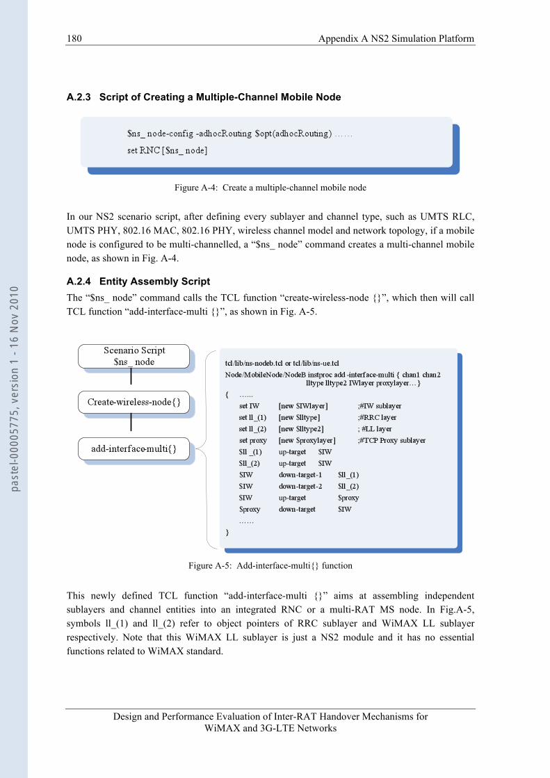
180 Appendix A NS2 Simulation Platform
Design and Performance Evaluation of Inter-RAT Handover Mechanisms for WiMAX and 3G-LTE Networks
A.2.3 Script of Creating a Multiple-Channel Mobile Node
Figure A-4: Create a multiple-channel mobile node
In our NS2 scenario script, after defining every sublayer and channel type, such as UMTS RLC, UMTS PHY, 802.16 MAC, 802.16 PHY, wireless channel model and network topology, if a mobile node is configured to be multi-channelled, a “$ns_ node” command creates a multi-channel mobile node, as shown in Fig. A-4.
A.2.4 Entity Assembly Script The “$ns_ node” command calls the TCL function “create-wireless-node {}”, which then will call TCL function “add-interface-multi {}”, as shown in Fig. A-5.
Figure A-5: Add-interface-multi{} function
This newly defined TCL function “add-interface-multi {}” aims at assembling independent sublayers and channel entities into an integrated RNC or a multi-RAT MS node. In Fig.A-5, symbols ll_(1) and ll_(2) refer to object pointers of RRC sublayer and WiMAX LL sublayer respectively. Note that this WiMAX LL sublayer is just a NS2 module and it has no essential functions related to WiMAX standard.
past
el-0
0005
775,
ver
sion
1 -
16 N
ov 2
010
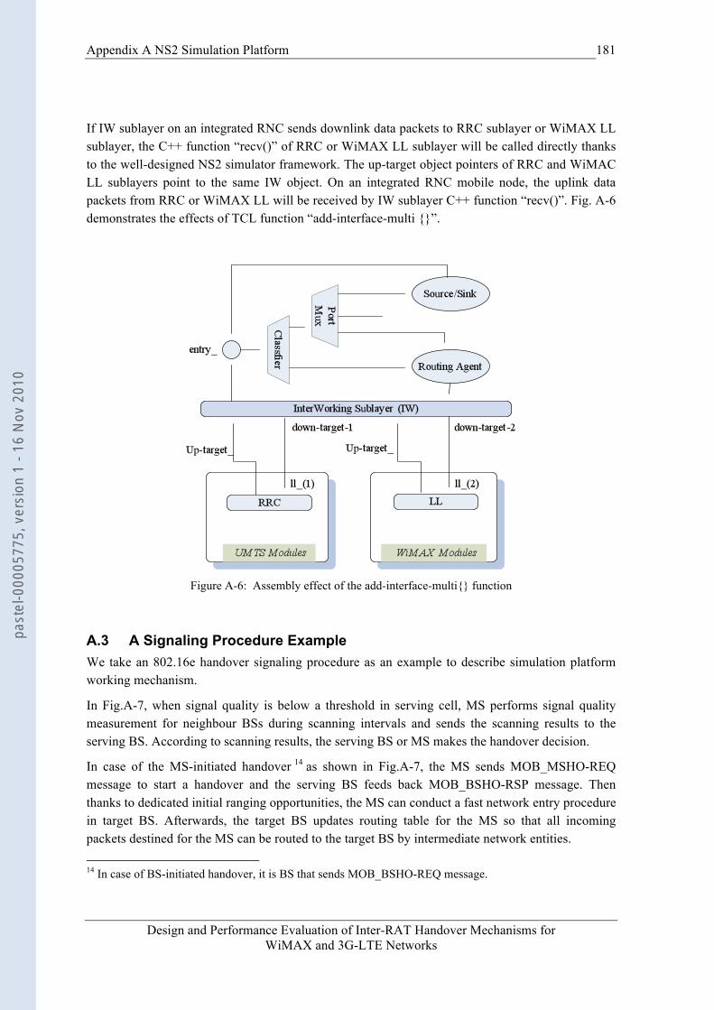
Appendix A NS2 Simulation Platform
Design and Performance Evaluation of Inter-RAT Handover Mechanisms for WiMAX and 3G-LTE Networks
181
If IW sublayer on an integrated RNC sends downlink data packets to RRC sublayer or WiMAX LL sublayer, the C++ function “recv()” of RRC or WiMAX LL sublayer will be called directly thanks to the well-designed NS2 simulator framework. The up-target object pointers of RRC and WiMAC LL sublayers point to the same IW object. On an integrated RNC mobile node, the uplink data packets from RRC or WiMAX LL will be received by IW sublayer C++ function “recv()”. Fig. A-6 demonstrates the effects of TCL function “add-interface-multi {}”.
Figure A-6: Assembly effect of the add-interface-multi{} function
A.3 A Signaling Procedure Example We take an 802.16e handover signaling procedure as an example to describe simulation platform working mechanism.
In Fig.A-7, when signal quality is below a threshold in serving cell, MS performs signal quality measurement for neighbour BSs during scanning intervals and sends the scanning results to the serving BS. According to scanning results, the serving BS or MS makes the handover decision.
In case of the MS-initiated handover 14 as shown in Fig.A-7, the MS sends MOB_MSHO-REQ message to start a handover and the serving BS feeds back MOB_BSHO-RSP message. Then thanks to dedicated initial ranging opportunities, the MS can conduct a fast network entry procedure in target BS. Afterwards, the target BS updates routing table for the MS so that all incoming packets destined for the MS can be routed to the target BS by intermediate network entities. 14 In case of BS-initiated handover, it is BS that sends MOB_BSHO-REQ message.
past
el-0
0005
775,
ver
sion
1 -
16 N
ov 2
010
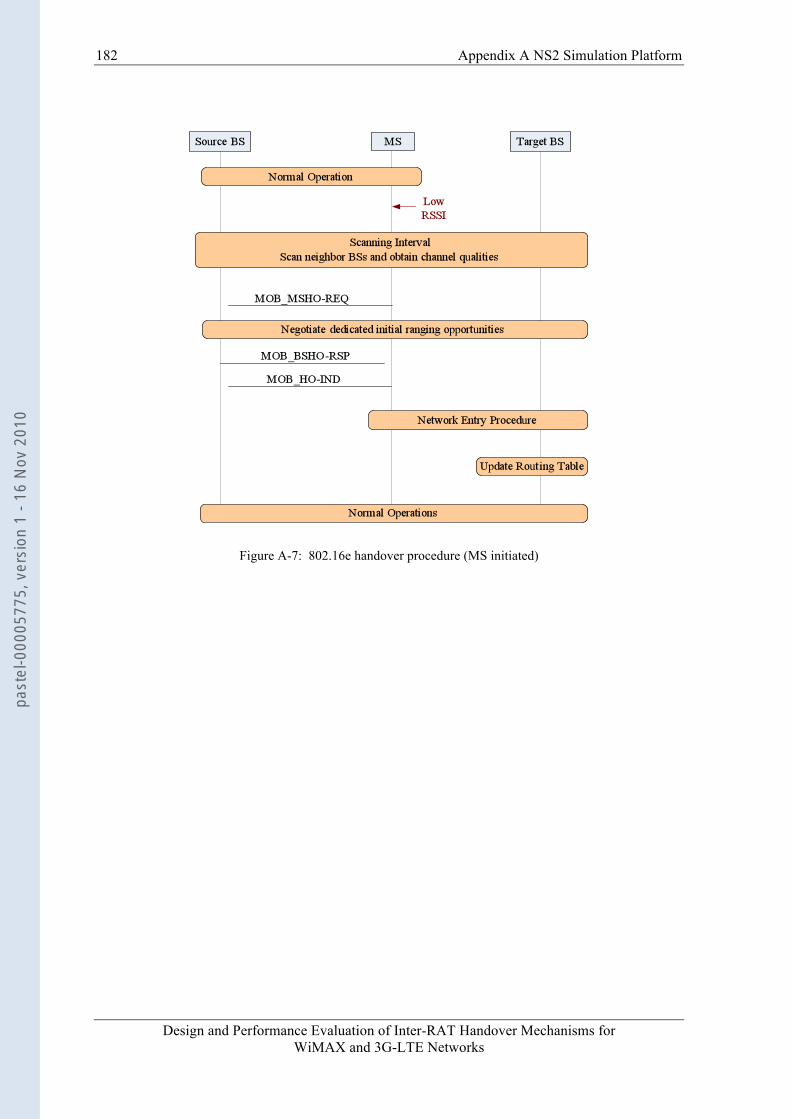
182 Appendix A NS2 Simulation Platform
Design and Performance Evaluation of Inter-RAT Handover Mechanisms for WiMAX and 3G-LTE Networks
Figure A-7: 802.16e handover procedure (MS initiated)
past
el-0
0005
775,
ver
sion
1 -
16 N
ov 2
010
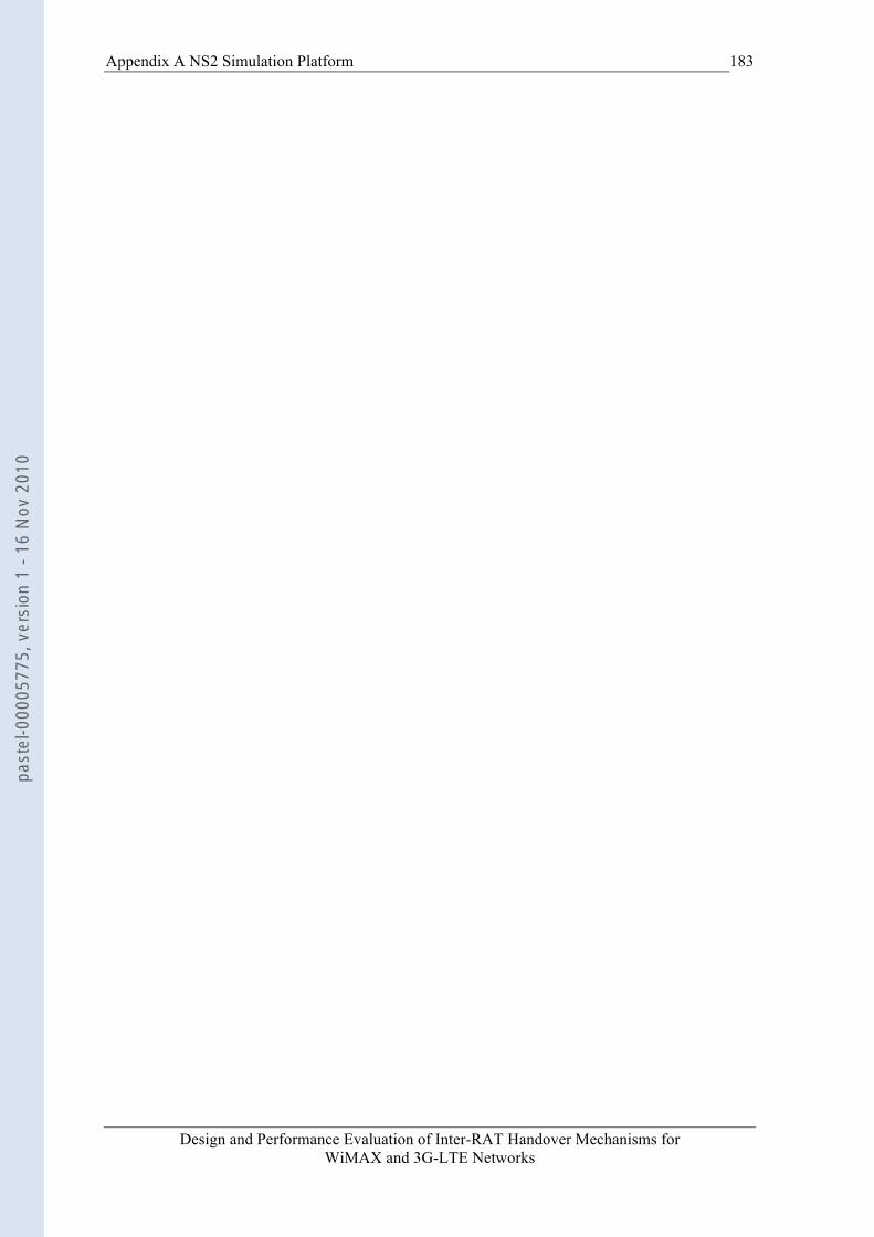
Appendix A NS2 Simulation Platform
Design and Performance Evaluation of Inter-RAT Handover Mechanisms for WiMAX and 3G-LTE Networks
183
past
el-0
0005
775,
ver
sion
1 -
16 N
ov 2
010

Design and Performance Evaluation of Inter-RAT Handover Mechanisms for WiMAX and 3G-LTE Networks
References
[1] D. Johnson, C. Perkins, and J. Arkko, "IP Mobility Support in IPv6", http://www.ietf.org/rfc/rfc3775.txt, IETF, June 2004.
[2] C. Perkins, "IP Mobility Support for IPv4". http://ietf.org/rfc/rfc3344.txt, IETF, Aug. 2002.
[3] L. Dimopoulou, G. Leoleis and I.O. Venieris, “Fast handover support in a WLAN
environment: challenges and perspectives”, IEEE Network, Vol. 19, pp: 14-20, May/June 2005
[4] R. Koodli. "Fast Handovers for Mobile IPv6", http://www.ietf.org/rfc/rfc4068.txt, IETF,
July 2005.
[5] R. Koodi, “Fast Handovers and Context Transfers in Mobile Networks”, ACM SIGCOMM Computer Communication Review, pp: 37-47, Oct. 2001
[6] H. Soliman, Flarion, C. Castelluccia, K. El Malki and L.Bellier, "Hierarchical Mobile
IPv6 Mobility Management (HMIPv6)", http://www.ietf.org/rfc/rfc4140.txt, IETF, Aug. 2005.
[7] H. Jung. H.S. Flarion and S.K. KNU, "Fast Handover for Hierarchical MIPv6 (F-
HMIPv6)", (work in progress). http://tools.ietf.org/wg/mipshop/draft-jung-mipshop-fhmipv6-00.txt, IETF, Oct. 2005.
[8] S. Yankov and S. Wiethoelter, “Handover Blackout Duration of Layer 3 Mobility
Management Schemes”, TKN Technical Report TKN-06-002, Berlin, May 2006
[9] R. Chakravorty, P. Vidales, K. Subramanian, I. Pratt and J. Crowcroft, “Performance Issues with Vertical handoffs-Experiences from GPRS cellular and WLAN Hot-spots Integration”, proceedings of the second IEEE annual conference on pervasive computing and communications (PERCOM’04), pp: 155-164
[10] J.C. Chen and H.W. Lin, ”A Gateway Approach to Mobility Integration of GPRS and
Wireless LANs”, IEEE Wireless Communications, pp: 86-95, Apr. 2005
[11] L. Morand and S. Tessier, “Global Mobility Approach with Mobile IP in ALL IP networks”, IEEE International Conference on Communications (ICC) 2002, pp: 2075-2079
[12] A.T. Campbell and J.G. Castellanos, “IP Micro-Mobility Protocols”, ACM
SIGMAOBILE Mobile Computing and Communications Review, Vol. 4, No. 4, pp: 45-53, Oct. 2000
[13] E. Fogelstroem, A. Jonsson and C. Perkins, “Mobile IPv4 Regional Registration (draft-
ietf-mip4-reg-tunnel-04)”, (work in progress). IETF, Oct. 23, 2006
past
el-0
0005
775,
ver
sion
1 -
16 N
ov 2
010

Reference
Design and Performance Evaluation of Inter-RAT Handover Mechanisms for WiMAX and 3G-LTE Networks
185
[14] R. Koodli and C. Perkins, “Mobile IPv4 Fast Handovers (Draft-ietf-mip4-fmipv4-02)”, (work in progress). IETF, Oct. 23, 2006
[15] T.M. Marc P.C. Xavier and S.R. Sebastia, ”A performance Study of Fast Handover for Mobile IPv6”, proceedings of the 28th annual IEEE international conference on local computer networks (LCN’03), 2003, pp: 1-10
[16] P.C. Xavier, T.M. Marc and H. Hannes, “A performance Comparison of Mobile IPv6,
Hierarchical Moile IPv6, Fast Handoffs for Mobile IPv6 and Their Combination”, ACM SIGMOBILE Mobile computing and Communications Review, Vol. 7, No. 4, pp: 5-19, Oct. 2003
[17] R. Hsieh, A. Seneviratne, H. Soliman and K. El-Malki, “Performance analysis on Hierarchical Mobile IPv6 with Fast-handoff over End-to-End TCP”, IEEE Global Telecommunications Conference, 2002 (GLOBECOM’02), pp: 2488-2492
[18] T.T. Kwon, M. Gerla, and S. Das, "Mobility management for VoIP service: Mobile IP vs. SIP". IEEE Wireless Communications, Vol. 9, No. 5, pp: 66 -75, Oct. 2002
[19] Y. Gwon, J. Kempf, and A Yegin, "Scalability and Robustness Analysis of Mobile IPv6,
Fast Mobile IPv6, Hierarchical Mobile IPv6, and Hybrid IPv6 Mobility Protocols using a Large-Scale Simulation". In 2004 IEEE International Conference on Communications (ICC2004), Vol. 7, pp: 4087- 4091, June 2004.
[20] R. Hsieh and A. Seneviratne, "A Comparison of Mechanisms for Improving Mobile IP Handoff Latency for End-to-end TCP". International Conference on Mobile Computing and Networking, 2003, pp: 29-41, Sept. 2003.
[21] I. Vivaldi, M.H. Habaebi, B.M. Ali, and V. Prakesh, "Fast Handover Algorithm for
Hierarchical Mobile IPv6 Macro-Mobility Management". In The 9th Asia-Pacific Conference on Communications. APCC 2003, Vol. 2, pp: 630-634, Sept. 2003
[22] J. Zhang, D.A.J. Pearce, and T.C. Tozer, "Two-way Registration: a Fast Handoff Scheme for IPv4 Macro-Mobility Management". In 15th IEEE International Symposium on Personal, Indoor and Mobile Radio Communications, Vol. 2, pp: 1252-1256, 5-8 Sept. 2004
[23] V. Gupta and D. Johnston, “IEEE 802.21, a generalized model for link layer triggers”,
IEEE 802.21 Media Independent Handoff Work Group, Mar 2004.
[24] S.D. Park and E. Njedjou, “L2 Triggers Optimized Mobile IPv6 Vertical Handover: The 802.11/GPRS Example”, draft-daniel-mip6-optimized-vertical-handover-00.txt, IETF, Jan. 2004
[25] F. Teraoka, K. Gogo, K.Mitsuya, K.Mitani, et al., “Unified L2 Abstraction for L3-Driven
Fast Handover”, Internet draft, draft-koki-mobopts-l2-abstractions-05.txt, IETF, June 23, 2006
past
el-0
0005
775,
ver
sion
1 -
16 N
ov 2
010
186 Reference
Design and Performance Evaluation of Inter-RAT Handover Mechanisms for WiMAX and 3G-LTE Networks
[26] S.H. Hwang, Y.H. Han and C.S. Hwang. “Signaling Time Analysis for Optimal Fast Handovers for Mobile IPv6”, Vehicular Technology Conference, 2004 (VTC2004-Fall). 2004 IEEE 60th, Vol. 5, pp: 3275-3280, 26-29 Sept. 2004
[27] E. Seurre, P. Savelli and P.J. Pietri, “GPRS for Mobile Internet”, Artech House Ltd, 2003
[28] S. Yoon, J. Jeong, C.K. Kim, W.J. Yang et.al., ” New Approach for Reducing DAD delay
using Link Layer Assistance in Mobile IPv6”, Multimedia and Ubiquitous Engineering, 2007 (MUE’07), pp: 1080-1085, 2007
[29] N. Cardwell, S. Savage and T. Anderson, “Modeling TCP Latency”, IEEE INFOCOM,
Vol. 3, pp1742-1751, Mar. 2000
[30] S. Mohanty and I.F. Akyildiz, “Performance Analysis of Handoff Techniques Based on Mobile IP, TCP-Migrate, and SIP”, IEEE Trans. On Mobile Computing. Vol.6, No.7, pp: 731-747, July 2007
[31] S. Mohanty and I.F. Akyildiz, ”A cross-layer (layer 2+3) handoff Management Protocol for Next-Generation Wireless Systems”, IEEE Trans. On Mobile Computing, Vol.5, No.10, pp: 1347-1360, Oct.2006
[32] J.O. Vatn, “IP telephone: mobility and security”, Doctoral thesis, May 2005, KTH, Royal Institute of Technology, Stockholm, Sweden
[33] J.L. Fan, “Desired Characteristics for an MBWA Air Interface”, IEEE C802.20-03/22
[34] J.Manner and M. Kojo, ”Mobility Related Terminology”, RFC 3753, June 2004
[35] 3GPP TS 25.304, “User Equipment (UE) procedures in Idle Mode and Procedures for Cell Reselection in Connected Mode”.
[36] 3GPP TS 04.18, “Technical Specification Group GSM/EDGE Radio Access Network;
mobile radio interface layer 3 specification; radio resource control protocol”
[37] 3GPP TS 05.08, “Technical Specification Group GSM/EDGE Radio Access Network; Radio subsystem link control (release 99)”
[38] 3GPP TS 25.304, “Technical Specification Group Radio Access Network; User
Equipment (UE) procedures in idle mode and procedures for cell reselection in connected mode”, v7.2.0
[39] 3GPP TS 25.331, “Technical Specification Group Radio Access Network; Radio
Resource Control (RRC); Protocol Specification (Release 7)”, v7.5 (2007-06)
[40] 3GPP TS 43.129, “Technical Specification Group GSM/EDGE” Radio Access Network; Packet-switched handover for GERAN A/Gb mode; Stage 2 (Release 7)”, V7.2.0
[41] J.P Romero, O. Sallent, R. Agusti and A.D.G. Miguel, “Radio Resource Management
Strategies in UMTS”, John Wiley & Sons, Ltd, 2005
past
el-0
0005
775,
ver
sion
1 -
16 N
ov 2
010

Reference
Design and Performance Evaluation of Inter-RAT Handover Mechanisms for WiMAX and 3G-LTE Networks
187
[42] 3GPP TR 25.922, “Technical Specification Group Radio Access Network; Radio resource management strategies (Release 7)”, V7.10
[43] 3GPP TR 25.931, “Technical Specification Group RAN; UTRAN functions, examples on
signaling procedures, (Realease 7)”, V7.4.0
[44] 3GPP TS 23.060,” Technical Specification Group Services and System Aspects; General Packet Radio Service (GPRS); Service description, stage 2 (Release 7)”, v7.4.0 (2007-03)
[45] 3GPP TS 45.008, “Technical Specification Group GSM/EDGE; Radio Access Network;
Radio subsystem link control (Release 7)”, V7.8.0 (2007-05)
[46] 3GPP TS 44.060, “Technical Specification Group GSM/EDGE Radio Access Network; General Packet Radio Service (GPRS), Radio Link Control/Medium Access Control (RLC/MAC) protocol (Release 7)”, V7.9.0 (2007-06)
[47] C. Johnson, R. Cuny and N. Wimolpitayarat, ”Inter-System Handover for Packet
Switched Services”, 2005 6th IEE International Conference on 3G and Beyond, pp: 1-5, 7-9 Nov. 2005
[48] G. Alsenmyr, J. Nergstrom, M. Hagberg, et.al., “Handover between WCDMA and
GSM”, Ericsson Review No.1, pp: 6-11, 2003
[49] N. Saravanan, N. Sreenivasulu, D. Jayaram, and A. Chockalingam, “Design and Performance Evaluation of an Inter-System Handover Algorithm in UMTS/GSM Network”, TENCON 2005, pp: 1-6, Nov. 2005
[50] D. Lugara, L. Ammi, M. Griguer and J. Tartiere, “UMTS to GSM handover based on compressed mode technique. “, IEEE International Conference on Communications, 2004 (ICC2004), pp: 3051-3055, 20-24, June 2004
[51] IEEE 802.16e-2005, “IEEE Standard for Local and metropolitan area networks Part 16:
Air Interface for Fixed and Mobile Broadband Wireless Access Systems Amendment 2: Physical and Medium Access Control Layers for Combined Fixed and Mobile Operation in Licensed Bands”, 2005
[52] 3GPP TS 25.323, “Technical Specification Group Radio Access Network; Packet Data
Convergence Protocol (PDCP) specification, (Release 7)”, V7.5.0
[53] G. Lanpropoulos, N. Passas, L. Merakos and A. Kaloxylos, “Handover Management Architectures in Integrated WLAN/Cellular Networks”, IEEE Communication Survey & Tutorials. Vol.7, No.4, pp: 30-44, Fourth Quarter 2005
[54] S.L. Tsao and C.C. Lin, “Design and Evaluation of UMTS/WLAN interworking
Strategies”, IEEE Vehicular Technology Conference, 2002 (VTC2002-Fall), pp: 777-781, 2002
[55] N. Vulic, I. Niemegeers and S.H de Groot, “Architectural Options for the WLAN
Integration at the UMTS Radio Access level”, IEEE Vehicular Technology Conference, 2004 (VTC 2004-Spring), pp: 3009-3013, May 17-19, 2004.
past
el-0
0005
775,
ver
sion
1 -
16 N
ov 2
010
188 Reference
Design and Performance Evaluation of Inter-RAT Handover Mechanisms for WiMAX and 3G-LTE Networks
[56] N. Dailly, P. Martins and P. Godlewski, “Performance evaluation of L2 handover
Mechanisms for Inter-Radio Access Networks”, IEEE Vehicular Technology Conference, 2006 (VTC2006-Spring), pp: 491-495, May 7-10, 2006
[57] J. Sachs, B. S. Khurana and P. Mahonen, “Evaluation of Handover Performance for TCP
Traffic Based on Generic Link Layer Context Transfer”, IEEE International Symposium on Personal, Indoor and Mobile Radio Communications, 2006 (PIMRC’06), pp: 1-5, Sept. 2006
[58] H. Inaura, G. Montenegro, R. Ludwig, A. Gurtov and F. Khafizov, ”TCP over Second
(2.5) and Third (3G) Generation Wireless Networks”, IETF, RFC 3481
[59] http://www.isi.edu/nsnam/ns
[60] H. Rutagemwa, S. Park, X.M. Shen, J.W. Mark, ”Robust Cross-layer Design of Wireless Profiled TCP Mobile Receiver for Vertical Handover”, IEEE Tans. On Vehicular Technology, Vol.56, No. 6, pp: 3899-3911, Nov. 2007
[61] N.C. Wang, Y.Y. Wang and S.C. Chang, “A Fast Adaptive Congestion Control Scheme
for Improving TCP Performance during Soft Vertical Handoff”, IEEE Wireless Communications and Networking Conference 2007 (WCNC 2007), pp: 3644-3649, 11-15 Mar. 2007
[62] Y. Gou D.A.J. Pearce and P.D. Mitchell, ”Receiver-based Vertical Handover Mechanism
for TCP Congestion Control”, IEEE Trans. On Wireless Communications, Vol. 5, No.10, pp: 2824-2833, Oct. 2006.
[63] T. Goff, J. Moronski and D.S. Phatak, ”Freeze-TCP: A true end-to-end TCP
enhandcement mechanism for mobile environments”, IEEE INFOCOM2000, pp: 1537-1545
[64] H.J. Huang and J.F. Cai, ”Adding Network-layer Intelligence to Mobile Receivers for
Solving Spurious TCP Timeout During Vertical Handoff”, IEEE Network, Vol. 20, No. 6, pp: 24-31, Nov.~Dec. 2006
[65] L.P. Ma, G.R. Arce and K.E. Barner, ”TCP Retransmission Timeout Algorithm Using
Weighted Medians”, IEEE Signal Processing Letter, Vol. 11, No.6, pp: 569-572, June 2004
[66] K. Brown and Suresh Singh, “M-TCP: TCP for Mobile Cellular Networks”, ACM SIGCOMM, Computer Communication Review, Vol. 27, Issue 5, pp: 19-43, Oct. 1997
[67] J.C. Moon and B.G. Lee, “Rate-Adaptive Snoop: A TCP Enhancement Scheme Over
Rate-Controlled Lossy Links”, IEEE/ACM Trans. on Networking, Vol.14, No.3, pp: 603-615, June 2006
[68] L. Kalampoukas, A. Varma and K.K. Ramakrishnan, “Explicit Window Adaptation: A
Method to Enhance TCP Performance”, IEEE/ACM Transaction on Networking. Vol. 10. No. 3, pp: 338-349, June 2002
past
el-0
0005
775,
ver
sion
1 -
16 N
ov 2
010

Reference
Design and Performance Evaluation of Inter-RAT Handover Mechanisms for WiMAX and 3G-LTE Networks
189
[69] B. Hamdaoui and P. Ramanathan, “A Network-layer Soft Handoff Approach for Mobile Wireless IP-Based Systems”, IEEE Journal on Selected Areas In Communications, Vol. 22, No.4, pp: 630-642, May 2004
[70] M. Afif, P. Martins, S. Tabbane and P. Godlewski, ”SCTP Extension for EGPRS/WLAN
Handover Data”, 31st IEEE Conference on Local Computer Networks, pp: 746-750, Nov. 2006
[71] 3GPP TS 36.211 v8.3.0, “Evolved Universal Terrestrial Radio Access (E-UTRA),
Physical Channels and Modulation (Rel.8)”, 2008-05
[72] S. Ikki and M.H. Ahmed, “Performance of Selection Combining In Cooperative Relaying Networks over Rayleigh Fading Channel”, Electrical and Computer Engineering, 2008, pp: 831-836, May 5-7 2008
[73] W.F. Su, A. K. Sadek and K.J.R. Liu, “SER Performance Analysis and Optimum Power
Allocation for Decoded-and-Forward Cooperation Protocol in Wireless Networks”, IEEE Wireless Communications and Networking Conference, 2005 (WCNC 2005), pp: 984-989, Mar. 2005
[74] M.R. Ramesh Kumar, S. Bhashyam and D. Jalihal, “Throughput Improvement for Cell-
Edge Users Using Selective Cooperation in Cellular Networks”, IEEE Wireless and Optical Communications Networks, 2008 (WOCN’08), pp: 1-5, May 2008
[75] K. G. Seddik, A.K. Sadek, A.S. Ibrahim and K.J.R. Liu, “Design Criteria and
Performance Analysis for Distributed Space-Time Coding”, IEEE Trans. On Vehicular Technology, Vol.57, No.4, pp: 2280-2291, July 2008.
[76] F.P. Kelly, A.K.Maulloo, and D.K.Tan, “Rate control for communication networks:
shadow prices, proportional fairness, and stability”, Journal of the Operational Research Society, Vol.49, pp: 237-252, 1998
[77] S.H.Low and D.E. Lapsley, “Optimization flow control – Part I: Basic algorithm and
convergence,” IEEE/ACM Trans. Networking, Vol. 7, pp: 861-874, June 1999
[78] J.W. Lee, M. Chiang and AR Calderbank, “Price-Based Distributed Algorithm for Rate-Reliability Tradeoff in Network Utility Maximization”, IEEE Journal on Selective Areas in Communications, Vol.24, No.5, pp: 962-976, May 2006
[79] V.Gupta, et.al., “IEEE802.21 Standard and Metropolitan Area Networks: Media
Independent Handover Services”, IEEE std 802.21-2008, 21 January 2009
[80] M. K. Karakayali, G.J. Foschini and R.A. Valenzuela, ”Network Coordination for Spectrally Efficient Communications In Cellular Systems”, IEEE Wireless Communications, Vol.13, No.4, pp: 56-61, Aug. 2006.
[81] P. Zhang, X.F. Tao, J.H. Zhang, et.al., “A Vision from the Future: Beyond 3G TDD”,
IEEE Communications Magazine, Vol. 43, No.1, pp: 38-44, Jan. 2005
past
el-0
0005
775,
ver
sion
1 -
16 N
ov 2
010
190 Reference
Design and Performance Evaluation of Inter-RAT Handover Mechanisms for WiMAX and 3G-LTE Networks
[82] P. McGuiggan, “GPRS in Practice, A Companion to the Specifications”, John Wiley & Sons Ltd. 2004
[83] Z.D. Lei, P.S. Chin Francois and Y.C. Liang, “Orthogonal Switched Beams for Downlink
Diversity Transmission”, IEEE Trans. on Antennas and Propagation, Vol.53, No.7, pp: 2169-2177, July 2005
[84] C. Makaya and S. Piere, “An Architecture for Seamless Mobility Support in IP-Based
Next-Generation Wireless Networks”, IEEE Trans. on Vehicular Technology, Vol.57, No.2, pp: 1209-1225, Mar. 2008
[85] Y.H. Han, J. Choi, S.H. Hwang., “Reactive Handover Optimization in IPv6-Based
Mobile Networks”, IEEE Journal on Selected Area in Communications, Vol.24, No.9, pp: 1758-1772, Sept. 2006
[86] I.F. Akyildiz and W.Y. Wang, “A Dynamic Location Management Scheme for Next-
Generation Multitier PCS Systems”, IEEE trans. on wireless communications, Vo.1, No.1, pp: 178-189, Jan. 2002
[87] W.H. Ma and Y.G. Fang, “Dynamic Hierarchical Mobility Management Strategy for
Mobile IP Networks”, IEEE Journal on Selected Areas in Communications, Vol.22, No.4, pp: 664-676, May 2004
[88] 3GPP TS 23.234 v6.5.0, “3GPP system to Wireless Local Area Network (WLAN),
interworking; System description (Release 6)”, 2005-06
[89] 3GPP TS 43.022, “Technical Specification Group GSM/EDGE; Radio Access Network; Functions related to Mobile Station (MS) in idle mode and group receive mode”, (Release 7), V7.2.0
[90] 3GPP TS 23.122, “Technical Specification Group Core Network and Terminals; Non-
Access-Stratum (NAS) functions related to Mobile Station (MS) in idle mode”, (Release 7), V7.2.0
[91] Y. Wang and F. Lin, “SER Performance Analysis and Power Allocation for Amplify-
and-Forward Relay Networks”, Wireless Communications, Networking and Mobile Computing, 2007 (WiCom 2007), pp: 1274-1277, Sept. 2007
[92] M. Meyer and J. Sachs, “Performance Evaluation of A TCP proxy In WCDMA
Networks”, IEEE Wireless Communications, Vol.10, Issue 5, pp70-79, Oct 2003
[93] F. Ren, X.Huang, F. Liu and C. Lin, “Improving TCP Throughput over HSDPA Networks”, IEEE, Trans. On Wireless Communications, Vol. 7, No.6, June 2008, pp: 1993-1998
[94] J.H. Hu, G. Feng and K. L. Yeung, “Hierarchical Cache Design for Enhancing TCP Over
Heterogeneous Networks With Wired and Wireless Links”, IEEE Trans. On Wireless Communications, Vol.2, No.2, March 2003, pp:205- 217
past
el-0
0005
775,
ver
sion
1 -
16 N
ov 2
010

Reference
Design and Performance Evaluation of Inter-RAT Handover Mechanisms for WiMAX and 3G-LTE Networks
191
past
el-0
0005
775,
ver
sion
1 -
16 N
ov 2
010
192 Reference
Design and Performance Evaluation of Inter-RAT Handover Mechanisms for WiMAX and 3G-LTE Networks
Publications
[1] Bin Liu, Philippe Martins, Abed Ellatif Samhat, Philippe Bertin, “The Operation Mode Selection in FMIPv6”, IEEE ISCC2008
[2] Bin Liu, Philippe Martins, Abed Ellatif Samhat, Philippe Bertin, “A Layer 2 Sheme of
inter-RAT handover between UMTS and WiMAX-VTC”, IEEE VTC fall’ 2008
[3] Bin Liu, Philippe Martins, Abed Ellatif Samhat, Philippe Bertin, “A Layer 2 Scheme for Inter-RAT Handover between UMTS and WiMAX in Tight Coupling Architectures”, IEEE PIMRC 2008
[4] Bin Liu, Philippe Martins, Abed Ellatif Samhat, Philippe Bertin, “A Cross-Layer Scheme
for Inter-RAT Handover from WiMAX to UMTS ”, IEEE Globecom2008
[5] Bin Liu, Philippe Martins, Abed Ellatif Samhat, Philippe Bertin, “Inter-RAT Handover Between UMTS And WiMAX”, Radio Communications, IN-TECH, ISBN 978-953-307-091-9
past
el-0
0005
775,
ver
sion
1 -
16 N
ov 2
010


![ABSTRACT of Doctoral Thesis - pavelstransky.cz€¦ · ABSTRACT of Doctoral Thesis ... The thesis is based particularly on published references [I, II, VII, VIII]. This abstract begins](https://static.fdocuments.fr/doc/165x107/5fbce8e8307fb30f38694377/abstract-of-doctoral-thesis-abstract-of-doctoral-thesis-the-thesis-is-based.jpg)