The Science and Technologies for Fusion Energy With Lasers and
14
690 IEEE TRANSACTIONS ON PLASMA SCIENCE, VOL. 38, NO. 4, APRIL 2010 The Science and Technologies for Fusion Energy With Lasers and Direct-Drive Targets J. D. Sethian, D. G. Colombant, J. L. Giuliani, Jr., R. H. Lehmberg, M. C. Myers, S. P. Obenschain, A. J. Schmitt, J. Weaver, M. F. Wolford, F. Hegeler, M. Friedman, A. E. Robson, A. Bayramian, J. Caird, C. Ebbers, J. Latkowski, W. Hogan, W. R. Meier, L. J. Perkins, K. Schaffers, S. Abdel Kahlik, K. Schoonover, D. Sadowski, K. Boehm, L. Carlson, J. Pulsifer, F. Najmabadi, A. R. Raffray, M. S. Tillack, G. Kulcinski, J. P. Blanchard, T. Heltemes, A. Ibrahim, E. Marriott, G. Moses, R. Radell, M. Sawan, J. Santarius, G. Sviatoslavsky, S. Zenobia, N. M. Ghoniem, S. Sharafat, J. El-Awady, Q. Hu, C. Duty, K. Leonard, G. Romanoski, L. L. Snead, S. J. Zinkle, C. Gentile, W. Parsells, C. Prinksi, T. Kozub, T. Dodson, D. V. Rose, T. Renk, C. Olson, N. Alexander, A. Bozek, G. Flint, D. T. Goodin, J. Hund, R. Paguio, R. W. Petzoldt, D. G. Schroen, J. Sheliak, T. Bernat, D. Bittner, J. Karnes, N. Petta, J. Streit, D. Geller, J. K. Hoffer, M. W. McGeoch, S. C. Glidden, H. Sanders, D. Weidenheimer, D. Morton, I. D. Smith, M. Bobecia, D. Harding, T. Lehecka, S. B. Gilliam, S. M. Gidcumb, D. Forsythe, N. R. Parikh, S. O’Dell, and M. Gorensek Manuscript received July 31, 2009; revised November 2, 2009. First pub- lished January 15, 2010; current version published April 9, 2010. This work was supported in part by the U.S. Department of Energy, by Department of Defense programs, Office of Defense Science and Inertial Fusion, National Nuclear Security Administration, and by the Office of Naval Research. J. D. Sethian, D. G. Colombant, J. L. Giuliani, Jr., R. H. Lehmberg, M. C. Myers, S. P. Obenschain, A. J. Schmitt, J. Weaver, and M. F. Wolford are with the Plasma Physics Division, Naval Research Laboratory, Washington, DC 20375 USA. F. Hegeler, M. Friedman, and A. E. Robson are with Commonwealth Technology, Inc., Alexandria, VA 22315USA. A. Bayramian, J. Caird, C. Ebbers, J. Latkowski, W. Hogan, W. R. Meier, L. J. Perkins, and K. Schaffers are with Lawrence Livermore National Labora- tory, Livermore, CA 94550-9234 USA. S. Abdel Kahlik, K. Schoonover, and D. Sadowski are with the Georgia Institute of Technology, Atlanta, GA 30332 USA. K. Boehm, L. Carlson, J. Pulsifer, F. Najmabadi, A. R. Raffray, and M. S. Tillack are with the University of California, San Diego, La Jolla, CA 92093 USA. G. Kulcinski, J. P. Blanchard, T. Heltemes, A. Ibrahim, E. Marriott, G. Moses, R. Radell, M. Sawan, J. Santarius, G. Sviatoslavsky, and S. Zenobia are with the University of Wisconsin—Madison, Madison, WI 53706 USA. N. M. Ghoniem, S. Sharafat, J. El-Awady, and Q. Hu are with the University of California at Los Angeles, Los Angeles, CA 90095 USA. C. Duty, K. Leonard, G. Romanoski, L. L. Snead, and S. J. Zinkle are with Oak Ridge National Laboratory, Oak Ridge, TN 37831 USA. C. Gentile, W. Parsells, C. Prinksi, T. Kozub, and T. Dodson are with Princeton Plasma Physics Laboratory, Princeton, NJ 08543-0451 USA. D. V. Rose is with Voss Scientific, Albuquerque, NM 87108 USA. T. Renk and C. Olson are with Sandia National Laboratories, Albuquerque, NM 87185-1194 USA. N. Alexander, A. Bozek, G. Flint, D. T. Goodin, J. Hund, R. Paguio, R. W. Petzoldt, D. G. Schroen, and J. Sheliak are with General Atomics, San Diego, CA 92121 USA. T. Bernat, D. Bittner, J. Karnes, N. Petta, and J. Streit are with Schafer Corporation, Livermore, CA 94551 USA. D. Geller and J. K. Hoffer are with Los Alamos National Laboratory, Los Alamos, NM 87545 USA. M. W. McGeoch is with PLEX Corporation, Brookline, MA 02146 USA. S. C. Glidden and H. Sanders are with Applied Pulsed Power, Inc., Freeville, NY 13068-0348 USA. D. Weidenheimer, D. Morton, and I. D. Smith are with L3 Pulse Sciences, Inc., San Leandro, CA 94577-5602 USA. M. Bobecia and D. Harding are with the Laboratory for Laser Energetics, University of Rochester, Rochester, NY 14623-1212 USA. T. Lehecka is with the Penn State Electro-Optics Center, State College, PA 16229 USA. S. B. Gilliam, S. M. Gidcumb, D. Forsythe, and N. R. Parikh are with The University of North Carolina at Chapel Hill, Chapel Hill, NC 27514 USA. S. O’Dell is with Plasma Processes, Inc., Huntsville, AL 35811-1558 USA. M. Gorensek is with Savannah River National Laboratory, Aiken, SC 29808 USA. Digital Object Identifier 10.1109/TPS.2009.2037629 Abstract—We are carrying out a multidisciplinary multi- institutional program to develop the scientific and technical basis for inertial fusion energy (IFE) based on laser drivers and direct- drive targets. The key components are developed as an integrated system, linking the science, technology, and final application of a 1000-MWe pure-fusion power plant. The science and technologies developed here are flexible enough to be applied to other size sys- tems. The scientific justification for this work is a family of target designs (simulations) that show that direct drive has the potential to provide the high gains needed for a pure-fusion power plant. Two competing lasers are under development: the diode-pumped solid-state laser (DPPSL) and the electron-beam-pumped krypton fluoride (KrF) gas laser. This paper will present the current state of the art in the target designs and lasers, as well as the other IFE technologies required for energy, including final optics (grazing incidence and dielectrics), chambers, and target fabrication, injec- tion, and tracking technologies. All of these are applicable to both laser systems and to other laser IFE-based concepts. However, in some of the higher performance target designs, the DPPSL will require more energy to reach the same yield as with the KrF laser. Index Terms—Fusion power generation, fusion reactors, laser amplifiers, laser fusion, magnetic fields, nanotechnology, optical tracking. I. I NTRODUCTION W E ARE carrying out a multidisciplinary multi- institutional program to develop the scientific and technical basis for the direct-drive approach to laser fusion energy. In this approach an array of lasers directly illumi- nates a cryogenic capsule (3–5-mm diameter) containing frozen deuterium–tritium that has been injected into a reaction cham- ber. The capsule is compressed and heated to fusion ignition and high gain. The fusion energy is absorbed by the chamber wall and blanket and then converted into electricity and, pos- sibly, hydrogen. The process is repeated at a repetition rate of about 5 Hz. Some of the advantages of this approach to fusion energy are as follows. 1) Direct drive has the simplest target physics. The main concern is hydrodynamic instability, which appears to be resolved with a combination of advances in laser 0093-3813/$26.00 © 2010 IEEE Authorized licensed use limited to: Univ of Calif San Diego. Downloaded on April 28,2010 at 22:10:39 UTC from IEEE Xplore. Restrictions apply.
Transcript of The Science and Technologies for Fusion Energy With Lasers and

690 IEEE TRANSACTIONS ON PLASMA SCIENCE, VOL. 38, NO. 4, APRIL 2010
The Science and Technologies for Fusion EnergyWith Lasers and Direct-Drive Targets
J. D. Sethian, D. G. Colombant, J. L. Giuliani, Jr., R. H. Lehmberg, M. C. Myers, S. P. Obenschain, A. J. Schmitt,J. Weaver, M. F. Wolford, F. Hegeler, M. Friedman, A. E. Robson, A. Bayramian, J. Caird, C. Ebbers, J. Latkowski,
W. Hogan, W. R. Meier, L. J. Perkins, K. Schaffers, S. Abdel Kahlik, K. Schoonover, D. Sadowski, K. Boehm,L. Carlson, J. Pulsifer, F. Najmabadi, A. R. Raffray, M. S. Tillack, G. Kulcinski, J. P. Blanchard, T. Heltemes,
A. Ibrahim, E. Marriott, G. Moses, R. Radell, M. Sawan, J. Santarius, G. Sviatoslavsky, S. Zenobia,N. M. Ghoniem, S. Sharafat, J. El-Awady, Q. Hu, C. Duty, K. Leonard, G. Romanoski, L. L. Snead,
S. J. Zinkle, C. Gentile, W. Parsells, C. Prinksi, T. Kozub, T. Dodson, D. V. Rose, T. Renk, C. Olson, N. Alexander,A. Bozek, G. Flint, D. T. Goodin, J. Hund, R. Paguio, R. W. Petzoldt, D. G. Schroen, J. Sheliak, T. Bernat,
D. Bittner, J. Karnes, N. Petta, J. Streit, D. Geller, J. K. Hoffer, M. W. McGeoch, S. C. Glidden, H. Sanders,D. Weidenheimer, D. Morton, I. D. Smith, M. Bobecia, D. Harding, T. Lehecka, S. B. Gilliam,
S. M. Gidcumb, D. Forsythe, N. R. Parikh, S. O’Dell, and M. Gorensek
Manuscript received July 31, 2009; revised November 2, 2009. First pub-lished January 15, 2010; current version published April 9, 2010. This workwas supported in part by the U.S. Department of Energy, by Department ofDefense programs, Office of Defense Science and Inertial Fusion, NationalNuclear Security Administration, and by the Office of Naval Research.
J. D. Sethian, D. G. Colombant, J. L. Giuliani, Jr., R. H. Lehmberg,M. C. Myers, S. P. Obenschain, A. J. Schmitt, J. Weaver, and M. F. Wolfordare with the Plasma Physics Division, Naval Research Laboratory, Washington,DC 20375 USA.
F. Hegeler, M. Friedman, and A. E. Robson are with CommonwealthTechnology, Inc., Alexandria, VA 22315 USA.
A. Bayramian, J. Caird, C. Ebbers, J. Latkowski, W. Hogan, W. R. Meier,L. J. Perkins, and K. Schaffers are with Lawrence Livermore National Labora-tory, Livermore, CA 94550-9234 USA.
S. Abdel Kahlik, K. Schoonover, and D. Sadowski are with the GeorgiaInstitute of Technology, Atlanta, GA 30332 USA.
K. Boehm, L. Carlson, J. Pulsifer, F. Najmabadi, A. R. Raffray, andM. S. Tillack are with the University of California, San Diego, La Jolla, CA92093 USA.
G. Kulcinski, J. P. Blanchard, T. Heltemes, A. Ibrahim, E. Marriott,G. Moses, R. Radell, M. Sawan, J. Santarius, G. Sviatoslavsky, and S. Zenobiaare with the University of Wisconsin—Madison, Madison, WI 53706 USA.
N. M. Ghoniem, S. Sharafat, J. El-Awady, and Q. Hu are with the Universityof California at Los Angeles, Los Angeles, CA 90095 USA.
C. Duty, K. Leonard, G. Romanoski, L. L. Snead, and S. J. Zinkle are withOak Ridge National Laboratory, Oak Ridge, TN 37831 USA.
C. Gentile, W. Parsells, C. Prinksi, T. Kozub, and T. Dodson are withPrinceton Plasma Physics Laboratory, Princeton, NJ 08543-0451 USA.
D. V. Rose is with Voss Scientific, Albuquerque, NM 87108 USA.T. Renk and C. Olson are with Sandia National Laboratories, Albuquerque,
NM 87185-1194 USA.N. Alexander, A. Bozek, G. Flint, D. T. Goodin, J. Hund, R. Paguio,
R. W. Petzoldt, D. G. Schroen, and J. Sheliak are with General Atomics,San Diego, CA 92121 USA.
T. Bernat, D. Bittner, J. Karnes, N. Petta, and J. Streit are with SchaferCorporation, Livermore, CA 94551 USA.
D. Geller and J. K. Hoffer are with Los Alamos National Laboratory,Los Alamos, NM 87545 USA.
M. W. McGeoch is with PLEX Corporation, Brookline, MA 02146 USA.S. C. Glidden and H. Sanders are with Applied Pulsed Power, Inc., Freeville,
NY 13068-0348 USA.D. Weidenheimer, D. Morton, and I. D. Smith are with L3 Pulse Sciences,
Inc., San Leandro, CA 94577-5602 USA.M. Bobecia and D. Harding are with the Laboratory for Laser Energetics,
University of Rochester, Rochester, NY 14623-1212 USA.T. Lehecka is with the Penn State Electro-Optics Center, State College,
PA 16229 USA.S. B. Gilliam, S. M. Gidcumb, D. Forsythe, and N. R. Parikh are with The
University of North Carolina at Chapel Hill, Chapel Hill, NC 27514 USA.S. O’Dell is with Plasma Processes, Inc., Huntsville, AL 35811-1558 USA.M. Gorensek is with Savannah River National Laboratory, Aiken,
SC 29808 USA.Digital Object Identifier 10.1109/TPS.2009.2037629
Abstract—We are carrying out a multidisciplinary multi-institutional program to develop the scientific and technical basisfor inertial fusion energy (IFE) based on laser drivers and direct-drive targets. The key components are developed as an integratedsystem, linking the science, technology, and final application of a1000-MWe pure-fusion power plant. The science and technologiesdeveloped here are flexible enough to be applied to other size sys-tems. The scientific justification for this work is a family of targetdesigns (simulations) that show that direct drive has the potentialto provide the high gains needed for a pure-fusion power plant.Two competing lasers are under development: the diode-pumpedsolid-state laser (DPPSL) and the electron-beam-pumped kryptonfluoride (KrF) gas laser. This paper will present the current stateof the art in the target designs and lasers, as well as the other IFEtechnologies required for energy, including final optics (grazingincidence and dielectrics), chambers, and target fabrication, injec-tion, and tracking technologies. All of these are applicable to bothlaser systems and to other laser IFE-based concepts. However, insome of the higher performance target designs, the DPPSL willrequire more energy to reach the same yield as with the KrF laser.
Index Terms—Fusion power generation, fusion reactors, laseramplifiers, laser fusion, magnetic fields, nanotechnology, opticaltracking.
I. INTRODUCTION
W E ARE carrying out a multidisciplinary multi-institutional program to develop the scientific and
technical basis for the direct-drive approach to laser fusionenergy. In this approach an array of lasers directly illumi-nates a cryogenic capsule (3–5-mm diameter) containing frozendeuterium–tritium that has been injected into a reaction cham-ber. The capsule is compressed and heated to fusion ignitionand high gain. The fusion energy is absorbed by the chamberwall and blanket and then converted into electricity and, pos-sibly, hydrogen. The process is repeated at a repetition rate ofabout 5 Hz. Some of the advantages of this approach to fusionenergy are as follows.
1) Direct drive has the simplest target physics. The mainconcern is hydrodynamic instability, which appears tobe resolved with a combination of advances in laser
0093-3813/$26.00 © 2010 IEEE
Authorized licensed use limited to: Univ of Calif San Diego. Downloaded on April 28,2010 at 22:10:39 UTC from IEEE Xplore. Restrictions apply.

SETHIAN et al.: SCIENCE AND TECHNOLOGIES FOR FUSION ENERGY WITH LASERS AND TARGETS 691
technology and target design. Other issues such aslaser–target coupling and suppression of laser–plasmainstabilities (LPI) can be and are being addressed onsubscale experiments.
2) Direct drive is best suited for energy production. It hasthe promise of power-plant-level pure-fusion gains withrelatively modest laser energies: around 1 MJ with con-ventional direct drive, or as low as 500 kJ with “shockignition,” as described in this paper.
3) Vast physics base: The scientific underpinnings for laserfusion are well established due to the work in the in-ertial confinement fusion (ICF) program carried out bythe U.S. National Nuclear Security Administration andinternational efforts. Note that the National Ignition Fa-cility (NIF) will use the indirect-drive approach for thefirst laboratory demonstration of thermonuclear ignition.This approach, where laser light is converted to X-raysthat drive the target, was chosen based on the primarymission of the NIF to study weapon physics. However,much of the underlying physics applies to the direct-driveapproach.
4) The laser, the most costly component (about one-thirdof the cost of the plant [1]), is modular. In most reactordesigns, the laser is composed of 20–60 identical beamlines. Thus, all the development can be done on one laserbeam line, which, when perfected, is then replicated tobuild the entire laser system. This lowers developmentcosts and risk.
5) Direct-drive targets are the simplest to manage. They arespherically symmetric shells that have been fabricated ina droplet generator, they require no preferred directionof illumination, and they have no hohlraum debris torecycle.
6) The main components are physically separated from thereaction chamber. Thus, they can be developed separatelybefore they are integrated into the system. This alsoreduces development costs. Just as importantly, it allowseconomical upgrades.
7) Power-plant studies show that the concept is economi-cally attractive [1], [2].
Our “business model” develops the key components forinertial fusion energy (IFE) as a coherent integrated system,simultaneously developing the needed science, technology, andengineering and always linking them to the final applicationof an attractive power plant. We leverage heavily off the targetphysics, laser development, and target fabrication technologiesdeveloped in the ICF program, and the materials and reactortechnologies developed in the magnetic fusion energy (MFE)program.
This paper describes some of the recent progress in devel-oping the key components. A description of earlier progressis given in the literature [3]. We start with a brief overview ofthe direct-drive target designs and then present the status of thetwo candidate laser systems: the diode-pumped solid-state laser(DPPSL), operating at the third harmonic with a wavelength of351 nm, and the electron-beam-pumped krypton fluoride (KrF)gas laser, operating at its fundamental wavelength of 248 nm.
We follow with a description of the progress made inthe other components: final optics (grazing incidence anddielectric mirrors); target fabrication, injection, and trackingtechnologies; and the development of the reaction chamber.
II. TARGET DESIGN
The scientific justification for this paper is a family of targetdesign simulations from several institutions that show thatdirect drive has the potential to provide the high gains neededfor a power plant based on pure-fusion energy [4]. The requiredgain is determined by the typical metric for an inertial-fusionpower plant: ηG > 10, where η is the laser efficiency and G isthe target gain. KrF lasers have a projected efficiency (wall plugto light on the target) of around 7%. Thus, the target gain needsto be in excess of 140. DPPSLs might be able to exceed 10%(at 351 nm), which would lower the gain requirement to 100.Obviously, the higher the gain the better, because it not onlydecreases recirculating power, it also provides a cushion in thetarget design to allow for real-world asymmetries, variations,etc. The following three types of target designs are considered.
1) Conventional direct-drive designs, with implosion veloc-ities of 300 km/s. These are applicable to both KrF andDPSSL lasers and show power-plant-class gains (> 140)at laser energies around 2.4 MJ [5], [6].
2) High-velocity (350–400-km/s) direct-drive designs thattake advantage of the deeper UV of a KrF laser. Codespredict gains > 50 at 500 kJ and > 140 (i.e., needed forenergy) around 1 MJ [7]. These are referred to as FusionTest Facility (FTF) designs.
3) “Shock ignition” designs have the prospect of requiringonly submegajoule (KrF) lasers for a power plant. Inshock ignition [8], a short high-intensity laser pulse ap-plied near peak compression drives a high-intensity shockto ignite the target. Shock ignition requires lower veloc-ity implosions than conventional direct drive (200–250versus 300–400 km/s). Shock ignition will provide simi-lar enhancement in DPSSL-based systems; however, thedriver energy needs to be higher to reach equivalent targetyield to KrF.
The gain curves for the three targets are shown in Fig. 1.Higher performance (gain) is predicted at lower laser energyfor a KrF (λ = 248 nm) than a DPPSL (λ = 351 nm). Thisis because the shorter wavelength of KrF both maximizes thecoupling efficiency and increases the threshold of LPIs. Thelatter means that a KrF target can be driven to higher implosionvelocities at lower laser energies. Alternatively, the KrF targetcan be driven with higher pressures and hence have betterhydrostability.
KrF lasers also produce the smoothest laser beam. Atechnique called induced spatial incoherence (ISI) [10], [11]produces very high quality focal profiles (< 0.2% spatialnonuniformities). That smoothness, coupled with the highbandwidth (∼3 THz), minimizes laser-induced perturbationsor “imprinting” on the target. A beam-smoothing techniquecalled smoothing by spectral dispersion (SSD) [12], [13]can effectively be applied to a DPPSL. While SSD does not
Authorized licensed use limited to: Univ of Calif San Diego. Downloaded on April 28,2010 at 22:10:39 UTC from IEEE Xplore. Restrictions apply.

692 IEEE TRANSACTIONS ON PLASMA SCIENCE, VOL. 38, NO. 4, APRIL 2010
Fig. 1. Gain curves from 1-D simulations of various high-performance direct-drive target designs. The shaded region shows sufficient gain for the pure-fusionpower plant. (Triangles) Conventional direct drive, KrF, or DPPSL (300-km/simplosion velocity). (Squares) FTF designs for KrF λ = 248 nm) and higherablation pressure implosion velocity of 350–450 km/s. (Circles) Shock ignitiontargets for KrF: Soft conventional compression (< 300 km/s) and then spike toshock heat to ignition. (Dashed lines) Fast ignition scaling [9] for KrF (248 nm)and DPPSL (351 nm).
produce as smooth a focal profile in all modes as ISI, it shouldbe adequate for the conventional high-gain target designs [14].
The net effect of all the advantages of KrF is illustratedwith one point design for a shock ignition target [4]. The gainsare predicted to be 92 with a 230-kJ KrF laser and 55 witha 450-kJ glass laser. The predicted fractions of incident laserlight coupled to the target are about 77% for a KrF laser andabout 55% for a DPPSL. These calculations assume that thelaser is “zoomed,” i.e., the spot size is decreased to follow theimploding pellet. Zooming increases the coupling efficiency byabout 35%. Note that shock ignition predicts comparable per-formance to fast ignition but does so without the need for com-plex targets and an additional more challenging type of laser.
The curves in Fig. 1 are a compilation of 1-D target simu-lations. Full 2-D simulations have been carried out for most ofthese designs. For example, 2-D simulations of shock ignitiontargets, which incorporate realistic nonuniformities in the targetsurface or laser, generally show about 65%–80% of the gainpredicted in one dimension [4].
The codes used to generate the gain curves in Fig. 1 havebeen benchmarked against experiments with planar target ex-periments that are within two to five times of the prototypicallaser fluence (2–3 kJ in 750-μm-diameter spot). While thehydrodynamic stability of these targets has been fairly wellestablished with a combination of simulations, experiments,and advances in target design and laser technologies, one areathat is difficult to predict is the effect of LPI. Any laser–targetdesign is subject to LPI. These laser-driven instabilities occurin the ablated plasma surrounding the pellet. LPI can producehigh-energy electrons that can preheat DT fuel, which lowersthe final density and, hence, fusion gain. LPI can also scatterthe laser beam, which reduces the drive efficiency. LPI is less ofa concern with shorter wavelength lasers because the threshold
is higher. The ponderomotive force driving LPI goes roughly asIλ2, where I is the intensity and λ is the wavelength. Thus, KrFwith its shorter wavelength (248 nm) should be more resistantto LPI than a DPPSL (351 nm). The experiments on the NikeKrF laser at the Naval Research Laboratory (NRL) have bornthis out [15]: The onset of LPI, as witnessed by the detection ofhard X-rays and scattered light, occurs at 1.7 × 10¹⁵ W/cm2. Incontrast, the LPI threshold for a glass laser operating at 351 nmis typically between 0.5 and 1.0 × 10¹⁵ W/cm2. (It should alsobe noted that a glass laser not only has a lower LPI threshold butalso requires more intensity to apply the same ablation pressureas KrF.)
The KrF intensities required to achieve the high implosionvelocities in the FTF class targets, as well as those requiredin the main drive of the shock ignition targets, range from 1.0to 2.0 × 10¹⁵ W/cm2. While many factors are in play here,it appears that the target requirements are below the observedKrF LPI threshold. Further experiments are being carried out tofully explore this region. On the other hand, the intensity of thespike in the shock ignition designs is around 2 × 10¹⁶ W/cm2
or well above the LPI threshold. However, LPI may not bean issue because the shock is applied late in time. The coreis already compressed, so preheat is not an issue. Moreover,simulations suggest that these “late” hot electrons, if they haveenergies below 100 keV, will be stopped by the outer surface ofthe dense compressed core and may result in a more efficientheating mechanism [8].
III. LASERS
Both KrF and DPPSL have the potential to be viable can-didates for a fusion energy system. KrF laser development iscarried out primarily with the Electra laser at NRL, whereasDPPSL development has been carried out with the Mercurylaser at LLNL. Both are developing technologies that arescalable to power-plant-size systems. Both have the potentialto meet the fusion energy requirements for cost, although ahigh-confidence estimate of the cost cannot be made until thetechnology is fully developed. KrF is a gas laser that is pumpedwith high-voltage high-current electron beams (500–800 keVand 100–500 kA). DPPSLs are solid-state lasers that arepumped with an array of high-efficiency (> 60%) high-power(> 100-W) diodes. The medium is Yb:S-FAP, but other media,including the NIF choice of Nd:glass, are under consideration.The fundamental wavelength is 1051 nm, but they can be tripledto 351 nm with 70% efficiency.
The Electra KrF laser runs at 2.5–5 Hz and produces between300 and 700 J in an oscillator mode. Based on development ofthe individual components, a fusion-energy-class KrF laser ispredicted to have a wall plug to laser light on target efficiencyin excess of 7%. Recent advances have dramatically increasedthe lifetime of the thin foil that separates the electron-beamdiode from the laser gas. Eliminating voltage reversals after themain power pulse prevents localized high-current emission thatcan melt pinholes into the foil. Electra has run 90 000 shotscontinuously at 2.5 Hz (10 h) and 50 000 shots in two runs at5 Hz. Over 320 000 laser shots were taken in an eight-dayperiod. The continuous run lifetime is now largely limited by
Authorized licensed use limited to: Univ of Calif San Diego. Downloaded on April 28,2010 at 22:10:39 UTC from IEEE Xplore. Restrictions apply.

SETHIAN et al.: SCIENCE AND TECHNOLOGIES FOR FUSION ENERGY WITH LASERS AND TARGETS 693
Fig. 2. NRL’s electron-beam-pumped Electra KrF laser system. The laseroutput window is between the two black magnet coils in the center of thephotograph. The arrow shows the laser path. The magnets guide the electronbeams into the laser gas. The pulsed-power systems for the electron beamsconsist of the blue pulse-forming lines and the attendant white tanks that flankthe laser cell.
erosion of the spark-gap-based pulsed power that drives theelectron beams. An all-solid-state pulsed-power system hasbeen built using components that have demonstrated lifetimesin excess of 300 000 000 shots. This integrated 180-kVdemonstrator module has run continuously at 10 Hz for over11 500 000 shots (> 13 days) and will become the basis fora system to be deployed on Electra. More details on Electratechnology and its performance can be found in [16]–[18]. Aphotograph of Electra appears in Fig. 2.
The Mercury DPPSL has produced greater than 50 J oflaser light (1051 nm) for over 300 000 shots in a series ofruns of 0.5–2 h at a repetition rate of 10 Hz. The overallefficiency of a DPPSL-based system is projected to be 10%(at the fundamental wavelength). Many advanced technologieshave been developed for Mercury, including high-power diodearrays, forced gas cooling of the laser crystal, high-power(200-W) Pockels cells, adaptive optics, and high-efficiencyfrequency conversion to the third harmonic. The high-powerdiode lifetime has been demonstrated to be over 140 000 000shots. A smaller front end for Mercury that uses the samediode/crystal architecture was recently completed and produces500 mJ. It has run for well over 10 000 000 shots with an rmsstability of 0.78%. A photograph of the Mercury laser appearsin Fig. 3. Further details can be found in [19]–[21].
In weighing the merits of these two approaches, they bothwarrant continued development. KrF has significant inherentphysics advantages for driving high-gain fusion-energy-classtargets, as described in Section II. Thermal management iseasier on account of the gas laser medium. Zooming is straight-forward with KrF and has been demonstrated by means of anoptical switchyard that progressively routes the laser throughdecreasing apertures [22]. The switchyard is located in the low-energy front-end laser that feeds all the amplifiers. However,when viewing fusion energy as a complete system, DPPSLsare a viable choice because of the longer wavelength, whichreduces optics damage considerations, the potential for higherwall plug efficiency, and the higher durability expected from anall-solid-state system. In addition, the cost of DPPSLs may bereasonable if current projections hold true that the price of the
Fig. 3. Close-up view of the LLNL Mercury DPPSL. In the foreground isone of the two amplifiers. The diode arrays are located at the ends of the twotrapezoidal light guides. The amplifier head, including the crystal, is located inthe white cylinder between the two guides. The light from the diodes is focusedonto the crystal from both sides.
Fig. 4. GIMM concept.
laser diodes (the most costly components in the system) willdrop significantly in the next 10–12 years.
IV. FINAL OPTICS
The final optics transport the laser beams to the reactionchamber center. They are the only optics to see the directemissions from the target. The front-runner final-optic conceptis a grazing incidence metal mirror (GIMM), as shown in Fig. 4.
This was first proposed in response to concerns over radiationdamage to multilayer dielectric mirrors [23]. The decision todevelop the GIMM is based on its potential for high laser dam-age threshold, its ability to withstand some uniform erosion,its simplicity, and its applicability to both KrF and DPPSLwavelengths. For example, the reflectivity at normal incidenceis about 93% at both 248- and 351-nm wavelengths [24]. TheGIMM would consist of an aluminum–alloy surface bonded toa cooled substrate that is resistant to neutron swelling (e.g.,aluminum, AlBeMet, or, possibly, SiC). Operation at a shallowangle (∼85◦) with s-polarized light gives higher reflectance(> 99%), hence less energy absorbed by the mirror. It alsolowers the average fluence on the surface due to the larger beamfootprint.
Experiments were conducted to determine the damagethreshold using a homogenized KrF laser: 700 mJ, 25 ns, and100 Hz. Damage was detected with a high-speed vision system
Authorized licensed use limited to: Univ of Calif San Diego. Downloaded on April 28,2010 at 22:10:39 UTC from IEEE Xplore. Restrictions apply.
694 IEEE TRANSACTIONS ON PLASMA SCIENCE, VOL. 38, NO. 4, APRIL 2010
Fig. 5. Observed laser damage threshold for various Al and Al alloy mirrors.The smaller color circles represent various alloys or deposition techniques. Thehighest performance was achieved with an Al–5% Cu solid solution alloy, asmarked by the large filled circle. That point does not represent a damage limitbut rather marks the end of that test.
Fig. 6. Views of entry points on a sphere for 40-beam illumination.(Left) View from the top of the sphere. The small dotted circles correspondto the ports on the lower half. (Right) Side view.
that images scattered light under the footprint of the mainlaser that results from both the laser itself and a HeNe probelaser. The main laser is allowed to fire only when the visionsystem indicates that the amount of scattered light is below anempirically established threshold. The reflectivity of the mirrordoes not change until damage is detected. As shown in Fig. 5,this type of mirror can resist at least 3.5 J/cm2 for more than10 000 000 shots [25].
The highest laser intensity survived to date was achieved withan Al–5% Cu solid solution alloy. Note that this is not a damagepoint but rather the highest fluence that could be applied withthe homogenized beam.
Based on the previous results, we have designed a final-optic train that can meet the requirements for illumination uni-formity, adequate tritium breeding, GIMM damage threshold,and neutron damage. The configuration is shown in Fig. 6.It was developed for the “conventional direct-drive” targetand is applicable to both DPPSLs and KrF. The chamber has40 beam ports, which are adequate for the illumination unifor-mity required by the target physics [26], [27]. The 40 beamports are arranged in six azimuthal tiers. There are four portsin the 24◦ tier (with 0◦ being defined as the pole) and eightports in each of the 52◦ and 79◦ tiers. Thus, the total numberof ports is 20 in the upper hemisphere and 20 in the lower
Fig. 7. Final-optic assembly showing the GIMM, the two dielectric mirrorsM1 and M2, and the predicted neutron flux on optical components. The plant“Lifetime” is assumed to be 30 years.
hemisphere. The lower sets of ports are offset by 22.5◦ fromthe corresponding upper ones so as to avoid any beam pointinginto an opposing beam, which carries a risk of optical damageif the target is not hit squarely. Note that the poles are left openfor target injection/tracking, and the equatorial belt is left openfor a magnetic intervention dump, as discussed in Section VIon reaction chambers. Other configurations are possible.
The GIMM is located in its own shielded housing at adistance of 24 m from the target. Each GIMM consists of 50separate elements, or GIMMlets, with dimensions of 15 cmhigh × 172 cm wide, and arranged in a 2 × 27 array. Thus,the entire GIMM is 3.44 m high × 4.05 m wide. The final-opticassembly is shown in Fig. 7, which also shows the predictedneutron flux and displacements per atom (dpa) for the power-plant lifetime.
The neutron flux was calculated using a newly developed toolthat directly couples a CAD-based engineering package witha neutronics code called Direct Accelerated Geometry MCNP[28]. This allows preservation of details with complex surfaceswithout a need for geometry simplification.
The simulation shows that the GIMM scatters a signifi-cant number of neutrons onto the dielectric mirrors over the30-year projected life of the plant. In keeping with the earlierconcern that dielectrics may not be able to withstand this levelof neutron fluence, we carried out a series of tests on dielectricmaterials. The hypothesis was that we could avoid the damageseen in previous studies if we matched the neutron-inducedswelling in the substrate with that in the mirror layers. Threedifferent dielectric stacks (mirror systems) were exposed atprototypical neutron fluence and temperature using the OakRidge National Laboratory (ORNL) HFIR.
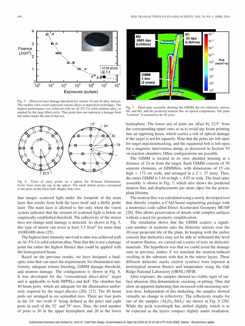
After exposure, the samples showed no visible signs of sur-face abrasion, film delamination, cracking, or pitting. They didshow an apparent darkening that increased with increasing neu-tron dose. Independent of this darkening, the samples showedvirtually no change in reflectivity: The reflectivity results forone of the samples (Al2O3/SiO2) are shown in Fig. 8 [29]:While the peak wavelength has shifted slightly, which is tobe expected as the layers compact slightly under irradiation,
Authorized licensed use limited to: Univ of Calif San Diego. Downloaded on April 28,2010 at 22:10:39 UTC from IEEE Xplore. Restrictions apply.
SETHIAN et al.: SCIENCE AND TECHNOLOGIES FOR FUSION ENERGY WITH LASERS AND TARGETS 695
Fig. 8. Reflectivity of (Al2O3/SiO2) dielectric mirror stack after exposure toneutrons from the ORNL HFIR.
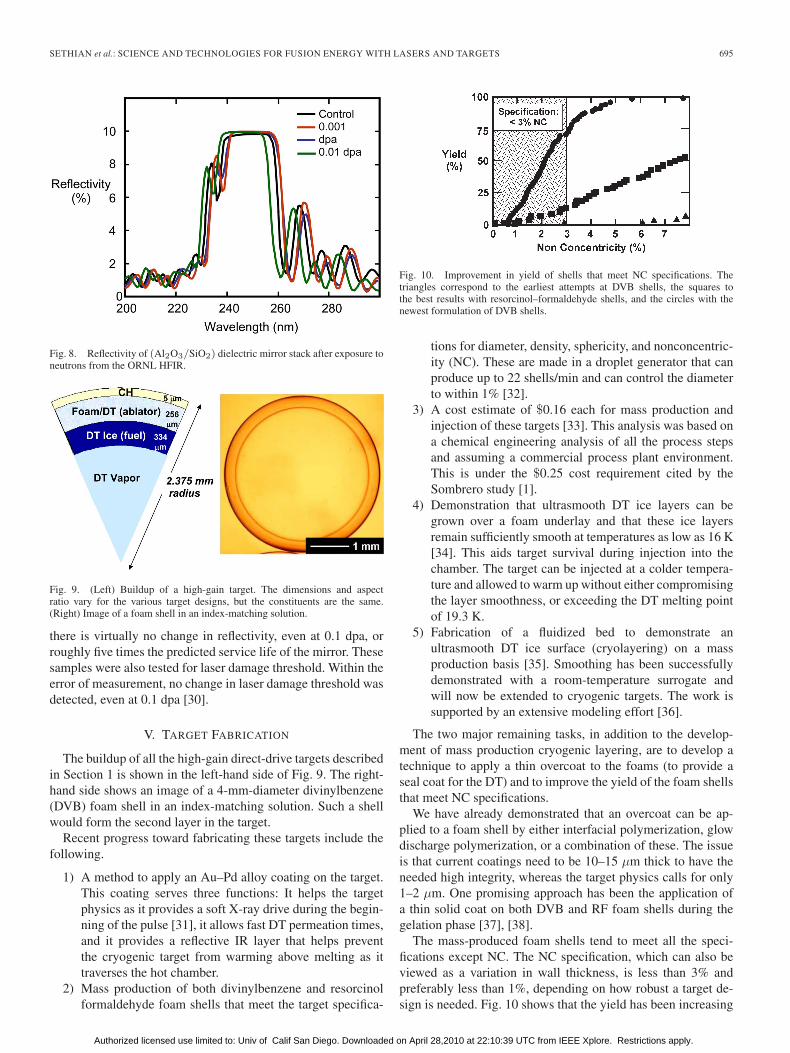
Fig. 9. (Left) Buildup of a high-gain target. The dimensions and aspectratio vary for the various target designs, but the constituents are the same.(Right) Image of a foam shell in an index-matching solution.
there is virtually no change in reflectivity, even at 0.1 dpa, orroughly five times the predicted service life of the mirror. Thesesamples were also tested for laser damage threshold. Within theerror of measurement, no change in laser damage threshold wasdetected, even at 0.1 dpa [30].
V. TARGET FABRICATION
The buildup of all the high-gain direct-drive targets describedin Section 1 is shown in the left-hand side of Fig. 9. The right-hand side shows an image of a 4-mm-diameter divinylbenzene(DVB) foam shell in an index-matching solution. Such a shellwould form the second layer in the target.
Recent progress toward fabricating these targets include thefollowing.
1) A method to apply an Au–Pd alloy coating on the target.This coating serves three functions: It helps the targetphysics as it provides a soft X-ray drive during the begin-ning of the pulse [31], it allows fast DT permeation times,and it provides a reflective IR layer that helps preventthe cryogenic target from warming above melting as ittraverses the hot chamber.
2) Mass production of both divinylbenzene and resorcinolformaldehyde foam shells that meet the target specifica-
Fig. 10. Improvement in yield of shells that meet NC specifications. Thetriangles correspond to the earliest attempts at DVB shells, the squares tothe best results with resorcinol–formaldehyde shells, and the circles with thenewest formulation of DVB shells.
tions for diameter, density, sphericity, and nonconcentric-ity (NC). These are made in a droplet generator that canproduce up to 22 shells/min and can control the diameterto within 1% [32].
3) A cost estimate of $0.16 each for mass production andinjection of these targets [33]. This analysis was based ona chemical engineering analysis of all the process stepsand assuming a commercial process plant environment.This is under the $0.25 cost requirement cited by theSombrero study [1].
4) Demonstration that ultrasmooth DT ice layers can begrown over a foam underlay and that these ice layersremain sufficiently smooth at temperatures as low as 16 K[34]. This aids target survival during injection into thechamber. The target can be injected at a colder tempera-ture and allowed to warm up without either compromisingthe layer smoothness, or exceeding the DT melting pointof 19.3 K.
5) Fabrication of a fluidized bed to demonstrate anultrasmooth DT ice surface (cryolayering) on a massproduction basis [35]. Smoothing has been successfullydemonstrated with a room-temperature surrogate andwill now be extended to cryogenic targets. The work issupported by an extensive modeling effort [36].
The two major remaining tasks, in addition to the develop-ment of mass production cryogenic layering, are to develop atechnique to apply a thin overcoat to the foams (to provide aseal coat for the DT) and to improve the yield of the foam shellsthat meet NC specifications.
We have already demonstrated that an overcoat can be ap-plied to a foam shell by either interfacial polymerization, glowdischarge polymerization, or a combination of these. The issueis that current coatings need to be 10–15 μm thick to have theneeded high integrity, whereas the target physics calls for only1–2 μm. One promising approach has been the application ofa thin solid coat on both DVB and RF foam shells during thegelation phase [37], [38].
The mass-produced foam shells tend to meet all the speci-fications except NC. The NC specification, which can also beviewed as a variation in wall thickness, is less than 3% andpreferably less than 1%, depending on how robust a target de-sign is needed. Fig. 10 shows that the yield has been increasing
Authorized licensed use limited to: Univ of Calif San Diego. Downloaded on April 28,2010 at 22:10:39 UTC from IEEE Xplore. Restrictions apply.

696 IEEE TRANSACTIONS ON PLASMA SCIENCE, VOL. 38, NO. 4, APRIL 2010
Fig. 11. Schematic of the “glint” system to perform the final mirror steeringto engage the target. The inset shows a photograph of the glint off the target.
from virtually zero to over 60% as new foam chemistries andprotocols are being developed [39].
Another approach to fabricating foam shells is the use ofmicrofluidics and electrophorisis to manipulate and form thefoam into shells while still in its liquid phase [40], [41].
VI. TARGET ENGAGEMENT
At first glance, precisely illuminating a pea-sized cryogenictarget that is injected into the center of a 10–22-m-diameterreaction chamber would seem to be a rather daunting task.Particularly considering that the required illumination precisionis 20 μm (rms between the centerline of laser beamlets tothe centerline of the target). However, we have developed aconcept and performed a successful proof-of-principle benchtest to show that it is feasible [42]. The concept is based on afour-stage process. The first stage employs optical sensors thatprecisely determine the target’s diameter and launch velocity.The second stage, encompassing most of the target’s trajectory,employs a separate optical sensor that continuously monitorslateral deviations of the target’s trajectory. In the third stage,immediately prior to arrival at the chamber center, the targetis illuminated by a short-pulse low-intensity “glint” laser. Theglint returns utilize the same optics as each beamlet, except thatthe glint passes through a monolithic wedge dichroic mirror.This compensates for the target motion after the glint and theoffset between the glint position and the target center. In thefourth stage, the fast-steering mirrors in the drive laser beamlines aim each drive beamlet to the position of the glint return.The beamlets then reflect off the front surface of the wedge toengage the target. A drawing of this fourth stage is shown inFig. 11.
We have demonstrated each stage of this process using asurrogate target (4-mm stainless-steel BB) falling at 5 m/sunder vacuum [43]. Optical measurements made with a pair ofcrossing sensors predict the time the target will arrive withinthe ±1-mm field of view assigned to the glint sensor. If thetarget cannot be regularly placed within the 1-mm field of view,lateral excursions during its trajectory can be monitored and thefield of view can be adjusted accordingly. These excursions aremonitored by a Poisson spot tracking system in which an axiallaser beam creates a bright diffraction spot at the precise center
of the target’s shadow. (The measured precision relative to a4-mm target at the center of a simulated 14-m chamber is 4 μmand updated every 3 ms.) Thus, these position measurementsallow the fast-steering mirror to apply most of its angularcorrection during a period in excess of 100 ms rather than thefew milliseconds it takes for the target to reach the chambercenter after being illuminated by the glint system (1–2 ms ina full-size IFE chamber). The precision with which the glintoffset can be measured with its camera sensor is 4 μm.
Our target engagement verification technique utilizes a sim-ulated driver beam diameter that is larger than the target andproduces a sharply focused halo around the target’s shadow.A camera is used together with an edge-finding algorithm tomeasure the centroid separation between the inner and outerboundaries of the halo. The measured verification error for afixed target is 4 μm. Currently, the engagement accuracy formoving targets is 34 μm rms. We anticipate with further im-provements (e.g., reducing the electrical noise associated withthe steering mirrors) that the total error in our demonstrationwill be less than the 20-μm requirement.
Most of the remaining error is from sources that are expectedto scale well to the increased distances required for IFE. Theeffect of fast-steering mirror electrical noise beam position isproportional to the maximum absolute distance through whichthe beam must be steered (±1–2 mm in our experiment andin a power plant). For the “glint” position measurements, theprecision in sensor space is simply a function of the interveningoptical magnification (assuming insignificant gas density vari-ations and no high-frequency vibrations of the optics), whichcan be preserved in a full-scale system.
The system has been designed assuming an injectionvelocity of 50 m/s. Higher injection velocity will obviouslyrequire faster position measurements and more rapid mirrorpositioning.
VII. REACTION CHAMBER
The reaction chamber is one of the most challenging aspectsin developing any practical fusion power plant. It is no differentfor laser fusion. The first wall (FW) of the reaction chambermust withstand the steady pulses of X-rays, ions, and neutronsfrom the target, must allow high-efficiency transport of thedeposited energy to the electrical generator, and must allowsufficient neutron transport to the tritium breeding blanket.One advantage that IFE has over an MFE system is that theemissions emanate from a point source away from the wall, soone can exploit 1/r2 scaling to reduce the wall loading. On theother hand, one disadvantage that IFE has over MFE is that theemissions are pulsed, so the instantaneous thermal loading canbe several orders of magnitude higher.
In designing the chamber FW, it is necessary to calculatefirst the emission or “threat” spectrum from the target. Table Igives the energy accounting, 100 ns after burn, of all theconstituents of a high-gain conventional direct-drive target. Inthis case, approximately 1.3% of the energy is released inX-rays (surface deposition, < 1 μm), 24% in ions (subsurfacedeposition, < 5 μm), and the remainder in neutrons (volumetricdeposition) [44]. This ratio is representative of all direct-drivetarget designs.
Authorized licensed use limited to: Univ of Calif San Diego. Downloaded on April 28,2010 at 22:10:39 UTC from IEEE Xplore. Restrictions apply.

SETHIAN et al.: SCIENCE AND TECHNOLOGIES FOR FUSION ENERGY WITH LASERS AND TARGETS 697
TABLE IENERGY ACCOUNTING FROM A HIGH-GAIN TARGET (LASER ENERGY OF 2.46 MJ AND GAIN OF 150)
Fig. 12. Threat spectra from the conventional direct drive shown in Table I.
Fig. 12 shows the ion and neutron spectra from the target.Pd and Au are in a thin layer to help the target performance, asdescribed in Section V.
The two physical processes of greatest concern are cyclicthermal loading and helium retention. Both of these canseverely degrade the thermomechanical properties of the FWmaterial. As in any fusion reactor, neutron damage is also aconsideration and needs to be addressed. However, that is on amuch longer damage cycle than the phenomena discussed here.
Cyclic thermal loading leads to stress-driven crack growthin the FW. Fig. 13 shows the temperature history of the wallas a function of depth [45]. This is for a target yield of154 MJ, a tungsten-armored FW at a radius of 6.5 m, and aninitial wall temperature of 600 ◦C. Note that the temperatureis highest within the first few micrometers. This is a directconsequence of the short penetration depth of the ions, theirrelatively short pulsewidth, and the fact that the ions carry arelatively high fraction of the reaction energy. The key concernwith respect to these temperature histories is cracking in tung-sten, although as discussed below this appears to be manage-able [46].
Helium retention is the more insidious problem. Becausethe helium migration distance is much shorter (50–100 nm)compared to the implantation distance (2–5 μm), helium tendsto coalesce into bubbles and at grain boundaries. The resulting
Fig. 13. Representative temperature history of the FW as a function of depthfrom the surface. This is for a tungsten-armored FW, at a radius of 6.5-m fusionyield of 154 MJ, and no gas inside the chamber. The details of the curveswill differ as the target yield and/or chamber radius is changed, but the basicbehavior is the same.
buildup in helium pressure exfoliates the surface. This is a well-known phenomenon [47].
Table II shows the five chamber concepts that were exploredto alleviate the effects of cyclic stress and helium retention.“Laser/target issues” refers to laser propagation, accurate targetplacement, target warm-up during injection, and target injectionvelocity.
Having a vacuum in the chamber is attractive becausesimulations show that there are no issues with either targetinjection/survival [45] or laser propagation. Because of that,efforts were concentrated on the first two approaches. Thesewill be discussed in this paper. Replaceable walls [48] werealso considered, albeit less vigorously. Refer to the literature forwork on issues for gas-filled chambers such as target survival,[45] chamber recovery, [49], and laser propagation [50]. A sum-mary of these chamber concepts is provided in the literature [51].
For solid-wall chambers, our choice for the FW is a thin(∼1-mm) tungsten armor bonded to a low-activation ferriticsteel substrate. This segregates the armor and structural func-tions. The tungsten was chosen to be thick enough to smooththe cyclic thermal stresses at the tungsten/steel interface, yetthin enough to ensure adequate heat removal before the next
Authorized licensed use limited to: Univ of Calif San Diego. Downloaded on April 28,2010 at 22:10:39 UTC from IEEE Xplore. Restrictions apply.

698 IEEE TRANSACTIONS ON PLASMA SCIENCE, VOL. 38, NO. 4, APRIL 2010
TABLE IIREACTION CHAMBER CONCEPTS
pulse. We have deployed a number of facilities to mimic thethreats onto this FW. The RHEPP facility at Sandia NationalLaboratories provides a source of repetitively pulsed high-energy ions [52]. A high-intensity infrared lamp at ORNL[53] mimics the cycle heat loading at the interface, and theDragonfire laser facility at UCSD is used to precisely study theevolution of long-term cyclic heating of the armor [54]. Theseexperiments are supported with the Unified Materials ResponseCode that is under development at UCLA and the University ofWisconsin [46], [55]. The objective is to develop a single toolto simulate all the relevant physics of the interaction betweentarget emissions and the FW, including deposition, thermalstress, mechanical stress, helium migration, thermal transport,and long-term behavior.
The experiments for looking at cyclic thermal stress suggestan upper limit on the tungsten armor of 2400 ◦C. Below that,there is little evidence of long-term mass loss. Tungsten doesexhibit some cracking, but the modeling suggests that thesecracks relieve the localized mechanical stress and they shouldnot propagate through to the substrate [46]. The experimentsalso show no long-term damage at the tungsten/steel interface.The 2400-◦C limit can be met with the conventional target in anevacuated chamber with a radius of 11 m.
Helium retention was studied with a series of exposureexperiments on the IEC electrostatic trap [56] at the Universityof Wisconsin. This produces full-power year (FPY) levels ofhelium fluence, but their energy represents only the lowest 5%of the prototypical helium energy spectrum. The experimentsconfirm that helium retention is a problem. The material quicklyexfoliates and loses mass within the equivalent of a few days offull-power operation [57]. These results have been successfullymodeled by UCLA [58]. However, newer research suggests twomeans to mitigate, if not downright prevent, helium exfoliation.One is based on the unique nature of helium implantation inan IFE system, and the other is the use of “nanoengineered”tungsten armor.
In an IFE system, helium is implanted in a short pulse intoa wall that is rapidly heated. The wall then cools before thenext shot. Given the relative immobility of helium clusters com-pared to monoatomic helium, the issue of studying prototypical
Fig. 14. Retained helium for different implantation histories.
implantation/anneal conditions may affect the relative retentionof helium. The hypothesis was supported by simulations fromUCLA [59] and a series of experiments at UNC Chapel Hill.[60]. In these experiments, a Van de graff Generator and ro-tating energy-degrader wheel generated helium ions with theprototypical target spectrum. Fig. 14 shows the amount ofhelium retained (as measured by the recoil proton spectrum)for three different implantation conditions into single-crystaltungsten. The implantation temperature was fixed at 850 ◦C,and the helium dose was fixed at 1015 He/cm2 (an FPY isabout 1020 He/cm2). The dose was deposited in 1, 10, 100, and1000 steps (1500 steps would be prototypical for this dose in apower plant). After each step, the sample was flash annealed to2500 ◦C. The retained helium was measured with proton recoilspectroscopy.
The trend is to retain less helium wherein the number of stepsis greater, which approaches the IFE prototypical implantationper pulse. However, other aspects are not prototypical: thetime scales for implantation and subsequent heating are a fewseconds long, the total fluence is only a small fraction of anFPY, and it is not practical to build an FW out of single-crystaltungsten. Nevertheless, the experiments suggest a potentialmethod to deal with helium retention.
An additional and possibly more effective approach is to usea “nanoengineered” tungsten armor. The armor is made from
Authorized licensed use limited to: Univ of Calif San Diego. Downloaded on April 28,2010 at 22:10:39 UTC from IEEE Xplore. Restrictions apply.

SETHIAN et al.: SCIENCE AND TECHNOLOGIES FOR FUSION ENERGY WITH LASERS AND TARGETS 699
TABLE IIIFRACTION OF RETAINED HELIUM FOR VARIOUS TUNGSTEN MORPHOLOGIES. 1016 He/cm2 TOTAL DOSE, 100-STEP, AND 500-STEP IMPLANTATIONS
porous tungsten whose scale length is less than the heliummigration distance (typically 50–100 nm). With this approach,the helium ions are slowed by the integrated mass of tungstenin their path, but wherever they finally come to rest, they arealways close to the tungsten surface. Engineered structures havethe added advantage of being more resistive to thermal cyclingfatigue as tungsten can expand without restriction. Modelingsupports this concept and also shows that thermal conductionto the substrate will not be an issue [61].
A series of experiments was performed with samples con-sisting of a solid tungsten undercoat and a porous tungstentopcoat. The porous tungsten was fabricated with a vacuumplasma spray process using 100-nm-size feedstock [62]. Thefirst material produced had a scale length of 500 nm, whichwas larger than desired. Nevertheless, the implantation resultsshowed evidence of lower helium implantation. The results areshown in Table III, which shows the percentage of retainedhelium for four different tungsten morphologies and a 100-stepanneal cycle [63], [64]. In this case, the total dose was1016 He/cm2, which represents about 2 h of full-power oper-ation. The retained helium was measured with proton recoilspectroscopy. The implanted helium was calculated from themeasured accelerator current density and exposure time.
The data show that less helium is retained in tungsten withsmaller grain size (or scale length). Postimplantation metrol-ogy corroborates this trend: Polycrystalline large-grain tung-sten exhibits blistering at 2 × 10¹⁵ He/cm2 and exfoliation at1016 He/cm2. In contrast, nanoengineered tungsten exhibits nosurface changes at 5 × 10¹⁵ He/cm2. The data in Table III alsoagree with the observation that less helium is retained witha larger number of implantation steps. Based on this, poroustungsten with scale sizes that are less than the 100-nm heliummigration distance is expected to retain even less helium.
Further indications that nanoengineered tungsten may bethe right approach were the results of recent helium implan-tation experiments with the University of Wisconsin electro-static trap. Recall that this facility produces helium fluencesthat can exceed an FPY, but that the helium energy is only30 keV and thus represents only the lower 5% of the spectrum.Fig. 15 shows the mass loss rate, as a function of heliumimplantation fluence, for the nanoengineered-tungsten-armoredsamples described earlier [65]. The fluence is also given asequivalent full-power days, assuming an 11-m-radius chamberand the conventional direct-drive target. The loss rate is rapidat first but slows considerably within the equivalent of 50 days.One interpretation is that the material is “adjusting” to a more
Fig. 15. Mass loss rate for the nanoengineered tungsten exposed to heliumions at prototypical fluences, and the lower 5% of the prototypical spectrum.
Fig. 16. Concept of magnetic intervention.
stable configuration. Another is that the early rapid loss may bedue to other phenomena that are endemic to the system. Thatis being addressed. Nevertheless, the total material loss overthe equivalent of 450 days of operation is only 1 μm of solidmaterial.
Another consideration for the nanoengineered material isrobustness to thermal cycling. A preliminary set of exposureson the Dragonfire laser facility show no detectable mass loss forup to 105 cycles if the peak temperature is kept below 2200 ◦C[66]. The material thermal response evolves during the first10–20 min of exposure, which requires further study beforedefinitive statements can be made. In light of these studies,nanoengineered tungsten, particularly if it can be made to therequired 50–100-nm scale length, may lead to a solution forthe FW.
Authorized licensed use limited to: Univ of Calif San Diego. Downloaded on April 28,2010 at 22:10:39 UTC from IEEE Xplore. Restrictions apply.

700 IEEE TRANSACTIONS ON PLASMA SCIENCE, VOL. 38, NO. 4, APRIL 2010
It is entirely possible that a solid wall can never be madeto withstand the direct emissions from the target. Althoughits simplicity warrants further exploration, prudence suggestsadding other options. One appealing approach is based on mag-netic intervention [67]. In this approach, a cusp magnetic fieldis imposed on the chamber and directs the ions through poloidalholes and an external belt. The ion energy is then absorbed inexternal dumps, thus isolating the energy absorption from thechamber. This process is shown schematically in Fig. 16.
The ions do not hit the chamber wall because their canonicalangular momentum must be conserved. The ions are born at thechamber center, where the magnetic field and the radius of theions are zero. Hence, their canonical angular momentum (Pθ =mruθ + (q/c)rAθ) is also zero (here, r is the radius of the ion,m is the ion mass, q = Ze is its charge, uθ is the azimuthalcomponent of velocity, and Aθ is the azimuthal component ofvector potential which, due to the axial symmetry, is the onlycomponent of A). The canonical angular momentum must beconserved in the absence of collisions, which is the case here.As the magnetic field in a cusp arrangement increases withdistance from the chamber center, the ions are confined to aregion defined by |Aθ| ≤ A∗, where A∗ = muc/q. As a result,the ions will never cross the field lines to hit the wall, and willleak out the poles and equatorial belt of the cusp.
Magnetic intervention has the following advantages.
1) The chamber radius can be much smaller and the choiceof FW materials can be expanded because the wall onlyneeds to absorb the energy of the X-rays, which carryjust 1% of the reaction energy. As an example, considera chamber of 5-m radius. If the FW is made of SiC(which has less X-ray stopping power and, hence, lowervolumetric deposition), the surface temperature wouldincrease by only about 130 ◦C.
2) A smaller chamber requires shorter distance for the in-jected target and, hence, a lower injection velocity. A5-m-radius chamber requires only 50 m/s as opposedto over 100 m/s for an 11-m-radius solid-wall chamber.The lower velocity can readily be achieved by simplemechanical or magnetic injectors. Smaller chambers alsorequire less placement accuracy.
3) The chamber can operate in vacuum, which facilitateschamber recovery for the next shot, assists accurate targetplacement (the most accurate target engagement benchtests were obtained with an evacuated system), and re-duces target injection warm-up as the only heat load isradiation from the chamber wall.
The concept and key physics of magnetic intervention weredemonstrated in a 1979 experiment at NRL, in which a puredeuterium plasma was formed in the center of the cusp geom-etry and allowed to leak out through the magnetic cusp [68].The plasma was formed by dropping a deuterium pellet into thechamber, disassociating it with a CO2 laser, and then ionizingit with an ND glass laser. This was arguably the first IFEexperiment. The plasma showed no sign of instability and,based on magnetic probes, laser scattering, and witness platemeasurements, was observed to exit the chamber through thecusps in a consistent well-defined pattern. Recent simulations
have successfully modeled the motion of the plasma [69]. Thecodes used in those simulations are now being used to developa magnetic-intervention-based chamber.
The challenge with magnetic intervention is dumping theions. Even though the cusp magnetic field spreads the ionsout in time, unless they are expanded onto an unrealisticallylarge area, i.e., comparable to that of the chamber, the powerper unit area incident on any surface is large. Thus, any solidsurface would be quickly ionized, making recovery for the nextshot problematic (we make the assumption that none of thedump material should be allowed back in the main chamber).Moreover, several species of ions are emitted, and none has awell-behaved energy distribution. For example, the hydrogenions carry only 19% of the total energy, but their longer rangerequires almost ten times as much mass to be stopped. Theseconsiderations lead to situating the dump outside the chamberand absorbing the energy in a volume rather than a surface.This, in turn, implies an external cavity filled with vapor or mist.We have evaluated a number of configurations [70]. The mostpromising one uses additional coils to divert the ions that escapefrom the toroidal belt downward into an external dump regionthat is filled with gallium mist. The ions that exit the poles ofthe cusp are absorbed in tubes filled with the same galliummist. The coils are configured so that the escaping plasma isoutside the beam ports shown in Fig. 6. Energy absorption is atwo-stage process. Some of the gallium absorbs the ion energyand is ionized and/or vaporized. The bulk of the gallium thencools the ions and vapor. The amount of gallium in the system ischosen so that the average temperature rise is less than 300 ◦C.Gallium is chosen because it is a liquid at slightly above roomtemperature, which alleviates start-up problems, and because ithas very low vapor pressure (10−6 torr at 720 ◦C). The lattermeans that it will not interfere with laser propagation, targetinjection, target warm-up, or chamber recovery.
One consideration with magnetic intervention is that thepolar field coils shown in Fig. 16 need to produce about 16 T onaxis in order to minimize the ions that emanate from the poles.While these are relatively simple small-bore (10-cm) solenoidalcoils and are within the state of the art [71], they are not routineitems. The main coils are on the order of 0.75 T and are wellwithin routine capabilities.
VIII. AUXILIARY SYSTEMS
In addition to the key components listed previously, we havealso produced conceptual designs for the other systems requiredfor a power plant. We have several blanket designs for bothmagnetic intervention and conventional chambers [72]. Thesedesigns use either liquid FLIBE or PbLi as the breeder materialand include the power conversion cycle. We have produced aconceptual design for a system to handle and process tritium,from recovering the unburned tritium in the chamber throughreprocessing and purification to filling a new target [73], [74].We have generated a conceptual design for the vacuum systemthat uses off-the-shelf components, costs under $20 million, andkeeps the vacuum below 10−3 torr [75]. We have generatedengineering concepts for the core of a laser IFE power plant[76] and undertaken a study to determine the feasibility of using
Authorized licensed use limited to: Univ of Calif San Diego. Downloaded on April 28,2010 at 22:10:39 UTC from IEEE Xplore. Restrictions apply.

SETHIAN et al.: SCIENCE AND TECHNOLOGIES FOR FUSION ENERGY WITH LASERS AND TARGETS 701
this approach to generate hydrogen. The study suggests that aPb–17Li blanket, with a silicon carbide composite (SiCf/SiC)structure operating at 1000 ◦C, could have more than 50%efficiency in generating hydrogen [77], [78]. The study assumesthe hybrid sulfur cycle in which the final products are justhydrogen and oxygen. We have also generated costing modelsto help determine the economic effects of reactor size, targetgain, laser cost, and repetition rate [79], [80].
IX. NEXT STEP
This work is applicable to a wide range of approaches tolaser fusion energy. One approach is the fusion–fission hybridsystem in which a lower gain fusion target is surrounded by afissile blanket to produce sufficient gain for a power plant. Thisis based on an extrapolation of present indirect-drive targets anda combination of NIF and Mercury laser technologies [81]. An-other approach is to exploit the higher gain targets afforded byKrF to develop a pure-fusion energy system. NRL has proposeda three-stage program to develop a laser fusion energy powerplant based on this approach [17]. The NRL program, based onthe FTF or shock ignition targets shown in Fig. 1, would usea single FTF to develop the physics, technologies, integrationissues, and the materials. As pointed out in the reference, thatpath could lead to the deployment of practical fusion power infar less time and with less risk than that in other approaches.
X. CONCLUSION
This paper has developed much of the scientific and tech-nical bases needed for a power plant based on laser fusionenergy. Credible approaches have been identified and are underdevelopment for virtually all the key components, includingtarget physics, two types of lasers, final optics, target fabricationand engagement, reaction chambers, and auxiliary components.Where possible, these have been backed with experiments,bench demonstrations, and simulations. We are technicallyready to take the next step to develop laser fusion energy.
ACKNOWLEDGMENT
The authors would like to thank the numerous scientists,technicians, engineers, programmers, support staff, and, mostimportantly, the over 40 students who contributed to and wereawarded advanced degrees through the program presented inthis paper.
REFERENCES
[1] W. R. Meier and C. W. von Rosenberg, Jr, “Economic modeling andparametric studies for SOMBRERO—A laser-driven IFE power plant,”Fus. Technol., vol. 21, pp. 1552–1556, 1992.
[2] I. N. Sviatoslavsky, M. E. Sawan, R. R. Peterson, G. L. Kulcinski,J. J. MacFarlane, L. J. Wittenberg, H. Y. Khater, E. A. Mogahed, andS. C. Rutledge, “A KrF laser driven inertial confinement fusion reactor‘SOMBRERO’,” Fus. Technol., vol. 21, pp. 1470–1474, 1992.
[3] J. D. Sethian, M. Friedman, R. H. Lehmberg, M. Myers, S. P. Obenschain,J. Giuliani, P. Kepple, A. J. Schmitt, D. Colombant, J. Gardner, F. Hegeler,M. Wolford, S. B. Swanekamp, D. Weidenheimer, D. Welch, D. Rose,S. Payne, C. Bibeau, A. Baraymian, R. Beach, K. Schaffers, B. Freitas,K. Skulina, W. Meier, J. Latkowski, L.J. Perkins, D. Goodin, R. Petzoldt,E. Stephens, F. Najmabadi, M. Tillack, R. Raffray, Z. Dragojlovic,
D. Haynes, R. Peterson, G. Kulcinski, J. Hoffer, D. Geller, D. Schroen,J. Streit, C. Olson, T. Tanaka, T. Renk, G. Rochau, L. Snead, N. Ghoneim,and G. Lucas, “Fusion Energy with Lasers, Direct Drive Targets, and DryWall Chambers,” Nucl. Fusion, vol. 43, no. 12, pp. 1693–1709, 2003.
[4] A. J. Schmitt, J. W. Bates, S. P. Obenschain, S. T. Zalesak, D. E. Fyfe, andR. Betti, “Direct drive fusion energy shock ignition designs for sub-MJlasers,” Fus. Sci. Technol., vol. 56, no. 1, pp. 377–383, Jul. 2009.
[5] S. E. Bodner, D. G. Colombant, A. J. Schmitt, J. H. Gardner,R. H. Lehmberg, and S. P. Obenschain, “Overview of new high gain targetdesign for a laser fusion power plant,” Fusion Eng. Des., vol. 60, no. 1,pp. 93–98, Jan. 2002.
[6] A. J. Schmitt, D. G. Colombant, A. L. Velikovich, S. T. Zalesak,J. H. Gardner, D. E. Fyfe, and N. Metzler, “Large-scale high-resolutionsimulations of high gain direct-drive inertial confinement fusion targets,”Phys. Plasmas, vol. 11, no. 5, pp. 2716–2722, May 2004.
[7] D. G. Colombant, A. J. Schmitt, S. P. Obenschain, S. T. Zalesak,A. L. Velikovich, J. W. Bates, D. E. Fyfe, and J. H. Gardner, “Direct-drivelaser target designs for sub-megajoule energies,” Phys. Plasmas, vol. 14,p. 056 317, 2007.
[8] R. Betti, C. D. Zhou, K.S. Anderson, L.J. Perkins, W. Theobald, andA.A. Solodov, “Shock ignition of thermonuclear fuel with highareal density,” Phys. Rev. Lett., vol. 98, no. 15, p. 155 001,Apr. 2007.
[9] R. Betti, A. A. Solodov, J. A. Delettrez, and C. Zhou, “Gain curves fordirect-drive fast ignition at densities around 300 g/cc,” Phys. Plasmas,vol. 13, no. 10, p. 100 703, Oct. 2006.
[10] R. H. Lehmberg and S. P. Obenschain, “Use of induced spatial incoher-ence for uniform illumination of laser fusion targets,” Opt. Commun.,vol. 46, no. 1, pp. 27–31, 1983.
[11] R. H. Lehmberg and J. Goldhar, “Use of incoherence to produce to pro-duce smooth and controllable irradiation profiles with KrF fusion lasers,”Fus. Technol., vol. 11, no. 3, pp. 532–541, 1987.
[12] S. Skupsky, R. W. Short, T. Kessler, R. S. Craxton, S. Letzring, andJ. M. Soures, “Improved laser-beam uniformity using the angular disper-sion of frequency-modulated light,” J. Appl. Phys., vol. 66, no. 8, p. 3456,1989.
[13] S. Skupsky and R. S. Craxton, “Irradiation uniformity for high-compression laser-fusion experiments,” Phys. Plasmas, vol. 6, no. 5,pp. 2157–2164, May 1999.
[14] R. H. Lehmberg and J. E. Rothenberg, “Comparison of optical beamsmoothing techniques for inertial confinement fusion and improvement ofsmoothing by the use of zero-correlation masks,” J. Appl. Phys., vol. 87,no. 3, pp. 1012–1022, Feb. 2000.
[15] Jim Weaver, Private Communication.[16] J. D. Sethian, M. Myers, J. L. Giuliani, Jr, F. Hegeler, M. Friedman,
M. Wolford, D. Rose, D. Weidenheimer, D. Morton, and D. Giorgi, “Elec-tra: A repetitively pulsed, electron beam pumped KrF laser to develop thetechnologies for fusion energy, Digest of Technical Papers,” in Proc. 15thIEEE Pulsed Power Conf., Monterey, CA, Jun. 2005, pp. 13–17.
[17] S. P. Obenschain, J. D. Sethian, and A. J. Schmitt, “Laser Based Fu-sion Test Facility,” Fus. Sci. Technol., vol. 56, no. 2, pp. 594–603,Aug. 2009.
[18] P. M. Burns, M. Myers, J. D. Sethian, M. F. Wolford, J. L. Giuliani,R. H. Lehmberg, M. Friedman, F. Hegeler, R. Jaynes, S. Abdel-Khalik,D. Sadowski, and K. Schoonover, “Electra: An Electron Beam PumpedKrF Rep-Rate Laser System for Inertial Fusion Energy,” Fus. Sci. Tech-nol., vol. 56, no. 1, pp. 346–351, Jul. 2009.
[19] A. Bayramian, P. Armstrong, E. Ault, R. Beach, C. Bibeau, J. Caird,R. Campbell, B. Chai, J. Dawson, C. Ebbers, A. Erlandson, Y. Fei,B. Freitas, R. Kent, Z. Liao, T. Ladran, J. Menapace, B. Molander,S. Payne, N. Peterson, M. Randles, K. Schaffers, S. Sutton, J. Tassano,S. Telford, and E. Utterback, “The Mercury Project: A high averagepower, gas-cooled laser for inertial fusion energy development,” Fus. Sci.Technol., vol. 52, no. 3, pp. 383–387, Oct. 2007.
[20] C. Ebbers, J. P. Armstrong, A. J. Bayramian, G. Beer, R. W. Campbell,D. C. Chen, R. R. Cross, A. C. Erlandson, B. L. Freitas, G. Huete,R. K. Lanning, J. Menapace, W. A. Molander, N. Schenkel,K. I. Schaffers, S. B. Sutton, J. B. Tassano, S. Telford, E. Utterback,J. A. Caird, C. P. Barty, B. H. Chai, and Y. T. Fei, “Solid state lasersfor fusion energy,” in Proc. 23rd Symp. Fusion Energy, San Diego, CA,May 31–Jun. 5, 2009.
[21] A. Bayramian, J. Armstrong, G. Beer, R. Campbell, R. Cross,A. Erlandson, B. Freitas, J. Menapace, W. Molander, K. Schaffers,S. Sutton, J. Tassano, S. Telford, C. Ebbers, J. Caird, and C. Barty,“Progress in diode pumped solid state laser driver development for inertialfusion energy,” in Proc. 18th Topical Conf. Fusion Energy, San Francisco,CA, Sep. 28–Oct. 2, 2008.
Authorized licensed use limited to: Univ of Calif San Diego. Downloaded on April 28,2010 at 22:10:39 UTC from IEEE Xplore. Restrictions apply.
702 IEEE TRANSACTIONS ON PLASMA SCIENCE, VOL. 38, NO. 4, APRIL 2010
[22] D. Kehne, Private Communication.[23] R. L. Bieri and M. W. Guinan, “Grazing incidence metal mirrors as the
final elements in a laser driver for inertial confinement fusion,” Fus.Technol., vol. 19, pp. 673–678, May 1991.
[24] M. S. Tillack, S. A. Payne, N. M. Ghoniem, M. R. Zaghloul, andJ. F. Latkowski, “Damage threats and response of final optics for laser-fusion power plants,” in Proc. Inertial Fusion Sci. Appl.. Kyoto, Japan,Sep. 2001, pp. 717–721.
[25] M. S. Tillack and J. E. Pulsifer, “Long-Term Survival of Grazing-Incidence Metal Mirrors for Laser Fusion,” Fus. Sci. Technol., vol. 56,no. 1, pp. 446–451, Jul. 2009.
[26] A. J. Schmitt and J. H. Gardner, “Illumination uniformity of laser fusionpellets using induced spatial incoherence,” J. Appl. Phys., vol. 60, no. 1,pp. 7–13, Jul. 1986.
[27] M. W. McGeoch, “Port placement and illumination uniformity” Proc.12th HAPL Meeting, Livermore, CA, Jun. 20, 2005. [Online]. Available:http://aries.ucsd.edu/HAPL/MEETINGS/0506-HAPL/08mcgeoch.ppt
[28] M. Sawan, A. Ibrahim, T. Bohm, and P. Wilson, “Nuclear assessmentof shielding configuration options for final optics of HAPL laser fu-sion power plant,” Fus. Sci. Technol., vol. 56, no. 2, pp. 756–760,Aug. 2009.
[29] L. L. Snead, K. Leonard, J. Jellison, M. Sawan, and T. Lehecka, “Per-formance of dielectric mirrors for inertial fusion application,” Fus. Sci.Technol., vol. 56, no. 2, pp. 1069–1077, 2009.
[30] T. Lehecka, Private Communication.[31] A. N. Mostovych, D. G. Colombant, M. Karasik, J. P. Knauer,
A. J. Schmitt, and J. L. Weaver, “Enhanced Direct-Drive Implosionswith Thin High-Z Ablation Layers,” Phys. Rev. Lett., vol. 100, no. 7,p. 075 002, 2008.
[32] B. A. Vermillion, B. W. McQuillan, L. C. Brown, D. T. Goodin, R. Paguio,J. E. Streit, D. G. Schroen, P. C. Goodman, and W. Maksaereekul, “MassProduction Methods for IFE Targets,” Fus. Sci. Technol., vol. 47, no. 4,pp. 1139–1145, Apr. 2005, AP-12.
[33] D. T. Goodin, N. B. Alexander, L. C. Brown, D. T. Frey, R. Gallix,C. R. Gibson, J. L. Maxwell, A. Nobile, C. Olson, R. W. Petzoldt,R. Raffray, G. Rochau, D. G. Schroen, M. Tillack, W. S. Rickman, andB. Vermillion, “A cost-effective target supply for inertial fusion energy,”Nucl. Fusion, vol. 44, no. 12, pp. S254–S265, Dec. 2004.
[34] J. K. Hoffer, J. D. Sheliak, D. A. Geller, D. Schroen, and P. Ebey, “Beta-layering in foam-lined surrogate IFE targets,” Fus. Sci. Technol., vol. 50,no. 1, pp. 15–32, Jul 2006.
[35] A. S. Bozek, N. B. Alexander, D. Bittner, L. Carlson, T. J. Drake,G. W. Flint, D. T. Frey, D. T. Goodin, S. Grant, J. F. Hund,J. D. Kilkenny, R. W. Petzoldt, D. G. Schroen, R. W. Stemke, J. E. Streit,and B. A. Vermillion, “The production and delivery of inertial fusionenergy power plant fuel: The cryogenic target,” Fusion Eng. Des., vol. 82,no. 15–24, pp. 2171–2175, Oct. 2007.
[36] K. J. Boehm, A. R. Raffray, N. B. Alexander, D. T. Frey, andD. T. Goodin, “Numerical and experimental analysis of using a fluidizedbed as a prototypic mass production device for IFE target layering,” Fus.Sci. Technol., vol. 56, no. 1, pp. 422–426, Jul. 2009.
[37] N. Petta, T. Bernat, J. Karnes, and J. Streit, “Development of targetsfor inertial fusion energy: Current experiments and future power gener-ation,” in Proc. 23rd Symp. Fusion Energy, San Diego, CA, May 31–Jun. 5, 2009.
[38] J. J. Karnes, N. M. Petta, and J. E. Streit, “Optimization of phase transfercatalysis for in situ coating of resorcinol formaldehyde targets,” FusionSci. Technol., vol. 55, no. 4, pp. 472–476, May 2009.
[39] D. T. Goodin, J. F. Hund, R. R. Paguio, D. G. Schroen, A. Nikroo,R. W. Petzoldt, N. B. Alexander, L. Carlson, M. Tillack, K. Boehm,J. D. Sheliak, D. A. Geller, J. K. Hoffer, and G. Flint, “Progress in‘Demonstrating Feasibility of the Target Supply for Laser Fusion’,” pre-sented at the 18th Topical Conf. Fusion Energy, San Francisco, CA,Sep. 28–Oct. 2, 2008.
[40] D. Harding, “A concept for mass producing IFE targets,” in 19th HighAverage Power Laser Program Workshop, Oct. 22–23, 2008. [Online].Available: http://aries.ucsd.edu/HAPL/MEETINGS/0810- HAPL/Day2/29%20HARDING%20Cryo%20Target%2023Oct0100davidhar.pdf
[41] D. R. Harding, D. H. Edgell, L. M. Elasky, R. Q. Gram, S. J. Verbridge,A. J. Weaver, M. D. Wittmaqn, and T. B. Jones, “Cryogenic targetsfor inertial confinement fusion experiments and future-energy applica-tions,” in Proc. 23rd Symp. Fusion Energy, San Diego, CA, May 31–Jun. 5, 2009.
[42] R. Petzoldt, N. Alexander, L. Carlson, G. Flint, D. T. Goodin, J. Spalding,and M. S. Tillack, “A continuous, in-chamber target tracking and engage-ment approach for laser fusion,” Fus. Sci. Technol., vol. 52, no. 3, pp. 454–458, Oct. 2007.
[43] L. Carlson, M. S. Tillack, T. Lorentz, N. Alexander, G. Flint,D. T. Goodin, and R. W. Petzoldt, “Improving the Accuracy of the TargetEngagement Demonstration,” Fus. Sci. Technol., vol. 56, no. 1, pp. 409–416, Jul. 2009.
[44] L. J. Perkins, M. Tabak, C. Bibeau, R. Beach, A. Ladran,C. Barty, J. Harte, J. Sethian, A. Schmitt, R. Betti, and C. Zhou,HAPL 13, University of Rochester, Nov. 8–9, 2005. [Online].Available:http://aries.ucsd.edu/HAPL/MEETINGS/0511-HAPL/Tuesday/05.0Perkins.ppt
[45] A. R. Raffray, “Threats, design limits and design windows for laserIFE dry wall chambers,” J. Nucl. Mater., vol. 347, no. 3, pp. 178–191,Dec. 2005.
[46] J. P. Blanchard and C. J. Martin, “Thermomechanical effects in a laser IFEfirst wall,” J. Nucl. Mater., vol. 347, no. 3, pp. 192–206, Dec. 2005.
[47] W. Wang, J. Roth, S. Lindig, and C. H. Wu, “Blister formation of tungstendue to ion bombardment,” J. Nucl. Mater., vol. 299, no. 2, pp. 124–131,Nov. 2001.
[48] M. E. Sawan, E. P. Marriott, C. S. Aplin, and L. L. Snead, “Mobiletiles for inertial fusion first wall/blanket,” in Proc. 23rd IEEE/NPSSSOFE (IEEE Cat. No. CFP09SOF-CDR), San Diego, CA, May 31–Jun. 5, 2009.
[49] Z. Dragojlovic and F. Najmabadi, “Effects of chamber geometry andgas properties on hydrodynamic evolution of IFE chambers,” Fus. Sci.Technol., vol. 47, no. 4, pp. 1152–1159, May 2005.
[50] J. A. Stamper, R. H. Lehmberg, T. Lehecka, A. V. Deniz, E. A. McLean,and J. D. Sethian, “Experimental studies of laser–target interactions inambient gas, under IFE conditions,” Nucl. Fusion, vol. 44, no. 7, pp. 745–751, Jul. 2004.
[51] J. P. Blanchard and R. Raffray, “Laser fusion chamber design,” FusionSci. Technol., vol. 52, no. 3, pp. 440–444, Oct. 2007.
[52] T. J. Renk, P. P. Provencio, T. J. Tanaka, C. L. Olson, R. R. Peterson,J. E. Stolp, D. G. Schroen, and T. R. Knowles, “Chamber wall materialsresponse to pulsed ions at power-plant level fluences,” J. Nucl. Mater.,vol. 347, no. 3, pp. 266–288, Dec. 2005.
[53] T. Hinoki, L. L. Snead, and C. A. Blue, “Development of refractoryarmored silicon carbide by infrared transient liquid phase processing,”J. Nucl. Mater., vol. 347, no. 3, pp. 207–216, Dec. 2005.
[54] F. Najmabadi, J. Pulsifer, and M. Tillack, “Update on armor simulationexperiments at Dragonfire facility,” in Proc. 15th High Average PowerLaser Program Workshop, General Atomics, San Diego, CA, Aug. 8–9,2006.
[55] J. P. Blanchard, Q. Hu, and N. Ghoniem, “A unified model for ion depo-sition and thermomechanical response in dry wall laser IFE chambers,”Fus. Sci. Technol., vol. 56, no. 1, pp. 341–345, Jul. 2009.
[56] S. J. Zenobia, R. F. Radela, B. B. Cipitia, and G. L. Kulcinski,“High temperature surface effects of He+ implantation in ICF fusionfirst wall materials,” J. Nucl. Mater., vol. 389, no. 2, pp. 213–220,May 2009.
[57] R. Radel and G. Kulcinski, “Effects of high temperature pulsed heliumimplantation on tungsten surface morphology,” Fus. Sci. Technol., vol. 52,no. 3, pp. 544–548, Oct. 2007.
[58] Q. Hu, S. Sharafat, and N. M. Ghoniem, “Modeling space–time dependenthelium bubble evolution in tungsten armor under IFE conditions,” Fus.Sci. Technol., vol. 52, no. 3, pp. 574–578, Oct. 2007.
[59] S. Sharafat, A. Takahashi, Q. Hu, and N. M. Ghoniem, “A description ofbubble growth and gas release of helium implanted tungsten,” J. Nucl.Mater., vol. 386–388, pp. 900–903, Apr. 2009.
[60] S. B. Gilliam, S. M. Gidcumb, D. Forsythe, N. R. Parikh, J. D. Hunn,L. L. Snead, and G. P. Lamaze, “Helium retention and surface blisteringcharacteristics of tungsten with regard to first wall conditions in an iner-tial fusion energy reactor,” Nucl. Instrum. Methods Phys. Res. B, BeamInteract. Mater. At., vol. 241, no. 1–4, pp. 491–495, Dec. 2005.
[61] S. Sharafat, N. M. Ghoniem, M. Anderson, B. Williams, J. P. Blanchard,and L. L. Snead, “Micro-engineered first wall tungsten armor for highaverage power laser fusion energy systems,” J. Nucl. Mater., vol. 347,no. 3, pp. 217–243, Dec. 2005.
[62] S. O’ Dell and R. Raffray, “Engineered Tungsten armorfor dry wall IFE chambers,” in Proc. 14th High AveragePower Laser Program Workshop, Mar. 21–22, 2006. [Online].Available: http://aries.ucsd.edu/HAPL/MEETINGS/0603-HAPL/Oral/29%20ODell–High%20Porosity%20Tungsten.ppt
[63] R. Parker, N. R. Parikh, R. G. Downing, S. O’Dell, G. Romanoski,T. Watkins, and L. Snead, “Helium retention in nano-porous tungsten im-planted with helium threat spectrum mimicking IFE reactor conditions,”in Proc. 17th High Average Power Laser Program Workshop, Oct. 30–31,2007. [Online]. Available: http://aries.ucsd.edu/HAPL/MEETINGS/0710-HAPL/Presentation/10b.%20Parikh%20Implanted%20Ion%20Issues.ppt
Authorized licensed use limited to: Univ of Calif San Diego. Downloaded on April 28,2010 at 22:10:39 UTC from IEEE Xplore. Restrictions apply.
SETHIAN et al.: SCIENCE AND TECHNOLOGIES FOR FUSION ENERGY WITH LASERS AND TARGETS 703
[64] N. Parikh, R. Parker, R. Downing, L. Cao, and L. L. Snead, “High dose ofhelium implanted in nano-cavity tungsten to evaluate threshold of surfaceblistering due to He bubble formation,” in Proc. Amer. Nucl. Soc. Annu.Meeting, Anaheim, CA, Jun. 8–12, 2008.
[65] S. Zenobia and G. Kulcinsi, “Retention and surface pore formation in he-lium implanted tungsten as a fusion first wall material,” Fus. Sci. Technol.,vol. 56, no. 1, pp. 352–360, Jul. 2009.
[66] F. Najmabadi and L. Carlson, “Engineered material exposure inDragonfire—A progress report,” in Proc. 19th High Average Power LaserProgram Workshop, Madison, WI, Oct. 22–23, 2008.
[67] Proposed by A. E. Robson.[68] R. E. Pechacek, J. R. Greig, M. Raleigh, D. W. Koopman, and
A. W. DeSilva, “Measurement of the plasma width in a ring cusp,” Phys.Rev. Lett., vol. 45, no. 4, pp. 256–259, Jul. 1980.
[69] D. V. Rose, E. A. Madrid, R. E. Clark, C. Thoma, D. R. Welch,A. E. Robson, J. D. Sethian, and J. L. Giuliani, “Magnetic inter-vention modeling,” in Proc. 18th High Average Power Laser Pro-gram Workshop, Santa Fe, NM, Apr. 8–9, 2008. [Online]. Available:http://aries.ucsd.edu/HAPL/MEETINGS/0804-HAPL/Day1/8.Rose.ppt
[70] A. R. Raffray, A. E. Robson, J. Sethian, C. Gentile, D. Rose, andM. Sawan, “Laser IFE direct drive chamber concepts with magnetic in-tervention,” Fus. Sci. Technol., vol. 56, no. 1, pp. 333–340, Jul. 2009.
[71] H. J. Schneider-Muntau, “Large bore high field magnets,” Nucl. Phys.B—Proc. Suppl., vol. 72, pp. 152–163, Mar. 1999.
[72] A. R. Raffray, A. E. Robson, M. E. Sawan, G. Sviatoslavsky,I. N. Sviatoslavsky, and X. Wang, “A self-cooled liquid breeder blanket fora laser IFE power plant with magnetic intervention,” Fusion Sci. Technol.,vol. 52, no. 3, pp. 603–608, Oct. 2007, and references therein.
[73] S. W. Langish, C. A. Gentile, T. Kozub, C. Priniski, J. Sethian,K. Sessions, B. Paul, L. Ciebiera, T. Dodson, and G. Gettelfinger,“IFE Power Reactor Plasma Exhaust Fuel Recovery System,” pre-sented at the 6th High Average Power Laser Program Workshop,Princeton, NJ, Dec. 12–23, 2006. [Online]. Available: http://aries.ucsd.edu/HAPL/MEETINGS/0612-HAPL/Presentation/Langish.ppt
[74] C. Gentile, T. Kozub, S. Langish, C. Pirinski, T. Dodson, F. Dahlgren,G. Gettlefinger, B. Paul, L. Ciebiera, K. Sessions, and J. Wermer, “Con-ceptual design of a plasma exhaust and fuel recovery system for an inertialfusion energy power reactor,” presented at the Proc. 22nd Symp. FusionEnergy, Albuquerque, NM, Jun. 17, 2007.
[75] C. A. Gentile, C. Priniski, J. Sethian, W. Blanchard, L. Ciebiera,F. Dahlgren, G. Gettelfinger, C. Jun, and S. Langish, “PumpingIFE chambers,” in Proc. 13th High Average Power Laser ProgramWorkshop, Nov. 8–9, 2005. [Online]. Available: http://aries.ucsd.edu/HAPL/MEETINGS/0511-HAPL/Tuesday/09.0Gentile.ppt
[76] C. A. Gentile, F. Dahlgren, T. A. Dodson, T. A. Kozub, M. W. McGeoch,C. D. Priniski, A. R. Raffray, A. E. Robson, D. V. Rose, M. E. Sawan,J. D. Sethian, I. J. Zatz, H. Zhang, and the HAPL Team, “IFE direct drivereactor core and primary sub-system development,” in Proc. 18th TopicalConf. Fusion Energy, San Francisco, CA, Sep. 28–Oct. 2, 2008.
[77] M. Gorensik, “Feasibility of hydrogen production using laser inertial fu-sion as the primary energy source,” Savvanah River Nat. Lab., Aiken, SC,Savvanah River National Laboratory Report, WSRC-STI-2006-00221,Nov. 3, 2006.
[78] M. Gorensik, “Feasibility of hydrogen production using laser inertialfusion as the primary energy source,” presented at the 16th High AveragePower Laser Program Workshop, Princeton, NJ, Dec. 12–23, 2006.[Online]. Available: http://aries.ucsd.edu/HAPL/MEETINGS/0612-HAPL/Presentation/Gorensek.ppt
[79] W. R. Meier, “How does laser cost scaling effect the power plant designoptimization?” presented at the 16th High Average Power Laser ProgramWorkshop, Dec. 12–23, 2006. [Online]. Available: http://aries.ucsd.edu/HAPL/MEETINGS/0612-HAPL/Poster/MeierPoster.ppt
[80] W. R. Meier, Dec. 2008. unpublished report.[81] E. Moses, “A sustainable nuclear fuel cycle based on laser inertial fusion
energy,” Fus. Sci. Technol., vol. 56, no. 2, pp. 547–565, Aug. 2009.
Authors’ photographs and biographies not available at the time ofpublication.
Authorized licensed use limited to: Univ of Calif San Diego. Downloaded on April 28,2010 at 22:10:39 UTC from IEEE Xplore. Restrictions apply.