Partage efficace de la bande passante entre les LSP de secours sous MPLS
SYNTHESIS OF PARAMETRISABLE FONTS BY SHAPE COMPONENTS
THÉSIS N˚ 1905 (1998)
PRÉSENTÉE AU DÉPARTEMENT D’INFORMATIQUE
ÉCOLE POLYTECHNIQUE FÉDÉRALE DE LAUSANNE
POUR L’OBTENTION DU GRADE DE DOCTEUR ÉS SCIENCES TECHNIQUES
PAR
Changyuan HU
Master of Computer Science and Technology, Nanjing University, Nanjing, Chinede nationalité chinoise
acceptée sur proposition du jury:
Prof. R. D. Hersch, directeur de thése
Prof. J.P. Buser, rapporteur
Dr. J. Gonczarowski, rapporteur
Dr. P. Karow, rapporteur
Lausanne, EPFL
1998


h, theique
earch
p mech. Ind ing the
ish ofoping
, for
Thanks
I wish to express my gratitude to my thesis advisor professor Roger D. Herschead of the Peripheral Systems Laboratory (LSP) of the EPFL, for the unopportunity he offered me to do research work in his laboratory, for guiding my resfrom the start to the end, and for providing me the best research environment.
Many thanks to all my colleagues in the LSP, who were always there to helwith small and big problems from updating computer systems to translating Frenthank in particular Dr. Patrick Emmel for helping me in understanding regulations asetting up the typeset format of this thesis. I thank Oscar Figueiredo for translatinabstract of this thesis to French. Isaac Amidror helped me to improve the Englsome parts of this thesis. I thank him. I also want to thank Fulco Houkes for develthe visual interface.
I wish to thank also professor André Gürtler, from Basel School of Designcorrecting the shape of our synthesized characters.
* * *
And finally, many thanks to my parents and all my family.

, bars, a font.es, itence,rs of
hichtrisableponentsblies ofents areponentss. The of the
asedendentctionameters or to ah vary high-rying Latin
rs ofcationents,
ationptical
Abstract
Typographic characters implicitly incorporate structure elements such as stemsround parts, arches and serifs, which are repeated throughout the characters ofAlthough this structure information is important when typographers design typefacis however not explicitly described in today’s outline font technology. As a consequcoherently varying the style of an outline font has to be done by modifying contouall characters in the font.
We propose in this thesis a new highly flexible font description method, wexplicitly describes characters as structure elements, i.e. as assemblies of parameshape components. Structure elements are either predefined parametrisable comsuch as stems or bars of parametrisable width, or can be described by assemparametrisable shape components such as sweeps and half-loops. Terminal elemeither predefined parametrisable serif shape components or are described by comsuch as sweeps and ellipse-like round parts and by boundary correcting pathcomponent based character synthesis method is illustrated by the reconstructionbasic characters of a few traditional text typefaces.
Using this method, we have developed a prototype of our component bparametrisable font synthesis system. Fonts are characterized by the font indepstructure of individual characters, by typeface category information (serif types, juntypes, squareness and obliqueness of round parts), by font-dependent global parand by further font-dependent parameters, referring either to a group of characterssingle character. By varying global parameters, derived fonts can be created whicin width, weight, contrast and shape. Such derived fonts are useful for producingquality condensed text, for varying the character weight and for optical scaling. Vathe typeface category information as well enables exploring parts of the traditionalcharacter design space.
We show the high quality of our synthesized fonts by synthesizing charactesome existing typefaces (Times, Helvetica and Bodoni). To demonstrate the applipotential of this method, we have successfully accomplished typographical experimwhich are beyond the capability of traditional outline font technology, such as variof weight, condensation, height proportion, contrast and oblique stress, and oscaling for printing at different physical sizes.
re telsments quition deent les de façonurs de
fontents deents des ou desmblages ou des soit desction de
ques estes.
e des sontr police,rrondiss à la
ractèreser dess sontse desn desrtaines
e la Pourcertainologie
aisse,r desractères.
Résumé
Les caractères typographiques comportent implicitement des éléments de structuque des jambages, des barres, des parties arrondies, des arches et des empattesont répétés sur tous les caractères d'une même police. Bien que cette informastructure soit importante et qu'elle soit présente lorsque les typographes dessinpolices, elle n'est pas exprimée explicitement par la technologie actuellereprésentation des caractères par contours. Par conséquent, pour modifier decohérente le style d'une police, il est actuellement nécessaire de modifier les contotous ses caractères.
Nous proposons dans cette thèse une nouvelle méthode de description deextrêmement souple qui décrit explicitement les caractères d'après leurs élémestructure, c'est-à-dire un assemblage d'éléments de forme paramétrable. Les élémstructure sont soit des composants paramétrables prédéfinis tels que des jambagebarres de largeur paramétrable, ou bien ils peuvent être décrits comme des assede composants géométriques paramétrables tels que des "tracés de pinceaux"demi-boucles. Les éléments terminaux sont soit des empattements paramétrablescomposants formés par des tracés de plume, des ellipses et des courbes de correcontour. La méthode de génération de caractères à partir de composants géométriillustrée par la reconstruction des caractères de base de quelques polices classiqu
En utilisant cette méthode nous avons réalisé un prototype de systèmgénération de polices à partir d'éléments de formes paramétrables. Les policecaractérisées par la structure inhérente des caractères indépendemment de leupar une information de catégorie de police (types de jambage, types de jonction, aronds ou carrés verticaux ou obliques), par des paramètres globaux spécifiquepolice et par d'autres paramètres spécifiques à la police relatifs à un groupe de caou à un caractère individuel. En jouant sur les paramètres globaux, on peut crépolices dérivées, variant en largeur, graisse, contraste et forme. De telles policeutiles pour produire du texte condensé de haute qualité, pour changer la graiscaractères ou bien pour l'ajustement optique des caractères. La modificatioparamètres relatifs à la catégorie de la police permet également d'explorer cevariations de parties de l'alphabet latin.
Nous montrons que la qualité des polices produites est bonne lors dreproduction des caractères de polices existantes (Times, Helvetica, Bodoni).explorer le potentiel d'application de cette méthode, nous avons mené à bien un nombre d'expériences typographiques au-delà des capacités de la techntraditionnelle de description de polices par contours telles que variation de grcondensation, modification de la proportion hauteur des minuscules / hauteumajuscules, augmentation du contraste, accentuation de la nature oblique des caarrondis et ajustement optique des caractères pour l'impression à différentes tailles
1
. . . . . 5
. . . . 7 . . . . 8. . . 10
. . . . 11 . . . 11 . . . 12. . . 13. . . 13. . . 16. . . 16. . . . 17. . . 18 . . 19 . . 19 . . 21. . . 24 . . . 28 . . 28 . . 30. . . 31. . . 34 . . 34 . . 38. . . 39. . . 41 . . . 41
. . . . 44 . . . 44. . . 45 . . . . 47 . . . 47. . . 47. . . 50 . . 51
Table Of Contents
1. Introduction 51.1 Preface . . . . . . . . . . . . . . . . . . . . . . . . . . . . . . . . . . . . . . . . . . . . . . . . . . . . . . . 1.2 Previous work in font parametrization . . . . . . . . . . . . . . . . . . . . . . . . . . . . . . . . 1.3 Content of this thesis . . . . . . . . . . . . . . . . . . . . . . . . . . . . . . . . . . . . . . . . . . . . .1.4 Terminology . . . . . . . . . . . . . . . . . . . . . . . . . . . . . . . . . . . . . . . . . . . . . . . . . . . .
2. Structures and components 112.1 Structure of characters . . . . . . . . . . . . . . . . . . . . . . . . . . . . . . . . . . . . . . . . . . .
2.1.1 Character structure. . . . . . . . . . . . . . . . . . . . . . . . . . . . . . . . . . . . . . . . . . .2.1.2 Structure element connecting graph . . . . . . . . . . . . . . . . . . . . . . . . . . . . .
2.1.2.1 Basic structure elements in structure graphs . . . . . . . . . . . . . . . . 2.1.2.2 Basic connections in structure graphs . . . . . . . . . . . . . . . . . . . . . 2.1.2.3 Design of structure graphs . . . . . . . . . . . . . . . . . . . . . . . . . . . . . . 2.1.2.4 Refinement of structure graphs. . . . . . . . . . . . . . . . . . . . . . . . . . .
2.2 Components . . . . . . . . . . . . . . . . . . . . . . . . . . . . . . . . . . . . . . . . . . . . . . . . . . . 2.2.1 Components for straight strokes . . . . . . . . . . . . . . . . . . . . . . . . . . . . . . . . 2.2.2 Curves suitable for font parametrization. . . . . . . . . . . . . . . . . . . . . . . . . . .
2.2.2.1 Modelling quadrant curves . . . . . . . . . . . . . . . . . . . . . . . . . . . . . . .2.2.2.2 Curvature of single curve segment . . . . . . . . . . . . . . . . . . . . . . . . .2.2.2.3 Curvatures of successively connected curve segments . . . . . . . .
2.2.3 Components for round parts . . . . . . . . . . . . . . . . . . . . . . . . . . . . . . . . . . .2.2.3.1 The loop component . . . . . . . . . . . . . . . . . . . . . . . . . . . . . . . . . . . .2.2.3.2 The half-loop component . . . . . . . . . . . . . . . . . . . . . . . . . . . . . . . .2.2.3.3 The sweep component . . . . . . . . . . . . . . . . . . . . . . . . . . . . . . . . .
2.2.4 Components for terminals . . . . . . . . . . . . . . . . . . . . . . . . . . . . . . . . . . . . . 2.2.4.1 The serif component . . . . . . . . . . . . . . . . . . . . . . . . . . . . . . . . . . . .2.2.4.2 The slant-serif component . . . . . . . . . . . . . . . . . . . . . . . . . . . . . . .2.2.4.3 The dot component . . . . . . . . . . . . . . . . . . . . . . . . . . . . . . . . . . . . 2.2.4.4 The path component . . . . . . . . . . . . . . . . . . . . . . . . . . . . . . . . . . .
2.3 Summary. . . . . . . . . . . . . . . . . . . . . . . . . . . . . . . . . . . . . . . . . . . . . . . . . . . . . . .
3. Font parametrization 433.1 Earmark-based refinement of structure graphs . . . . . . . . . . . . . . . . . . . . . . . .
3.1.1 Serif styles . . . . . . . . . . . . . . . . . . . . . . . . . . . . . . . . . . . . . . . . . . . . . . . . .3.1.2 Analysis on common earmarks . . . . . . . . . . . . . . . . . . . . . . . . . . . . . . . . .
3.2 Parametrisable character synthesis methods . . . . . . . . . . . . . . . . . . . . . . . . . .3.2.1 Component position dependency . . . . . . . . . . . . . . . . . . . . . . . . . . . . . . .
3.2.1.1 Relationships between components . . . . . . . . . . . . . . . . . . . . . . . 3.2.1.2 Component dependency graph . . . . . . . . . . . . . . . . . . . . . . . . . . . 3.2.1.3 Methods to specify dependency . . . . . . . . . . . . . . . . . . . . . . . . . . .
2
. . . 52 . . 53 . . 54 . . 55. . . 56. . 56 . . 60 . . 61 . . . 62 . . . 65 . . . 65 . . . 67. . . 67 . . 68 . . 69. . . 70 . . . 72 . . . 74
. . . . 75. . . . 76 . . . 78 . . . 79. . . 81 . . . 81. . . 83 . . . 84 . . . 84. . . 86. . . 88 . . 88. . . 89. . 91. . 92. . . 92 . 92. . 93 . . . 95 . . . 97
. . . 99
3.2.2 Component shape tuning. . . . . . . . . . . . . . . . . . . . . . . . . . . . . . . . . . . . . .3.2.2.1 Dimension. . . . . . . . . . . . . . . . . . . . . . . . . . . . . . . . . . . . . . . . . . . .3.2.2.2 Orientation . . . . . . . . . . . . . . . . . . . . . . . . . . . . . . . . . . . . . . . . . . .3.2.2.3 Curvature. . . . . . . . . . . . . . . . . . . . . . . . . . . . . . . . . . . . . . . . . . . . .
3.2.3 Boundary correction . . . . . . . . . . . . . . . . . . . . . . . . . . . . . . . . . . . . . . . . . 3.2.3.1 Trim extension of component outlines . . . . . . . . . . . . . . . . . . . . . . 3.2.3.2 Smooth corner of intersected components . . . . . . . . . . . . . . . . . . .3.2.3.3 Hand tuned boundary correction . . . . . . . . . . . . . . . . . . . . . . . . . .
3.2.4 The complete parametrisable character synthesis method . . . . . . . . . . . .3.3 Parameter files . . . . . . . . . . . . . . . . . . . . . . . . . . . . . . . . . . . . . . . . . . . . . . . . . .
3.3.1 Coordinate system . . . . . . . . . . . . . . . . . . . . . . . . . . . . . . . . . . . . . . . . . . .3.3.2 Parameter hierarchy. . . . . . . . . . . . . . . . . . . . . . . . . . . . . . . . . . . . . . . . . .
3.3.2.1 Global parameters and local parameters . . . . . . . . . . . . . . . . . . . 3.3.2.2 Local parameter grouping. . . . . . . . . . . . . . . . . . . . . . . . . . . . . . . .3.3.2.3 The parameter hierarchy . . . . . . . . . . . . . . . . . . . . . . . . . . . . . . . . .
3.3.3 An example of parameter files. . . . . . . . . . . . . . . . . . . . . . . . . . . . . . . . . . 3.4 Technical issues regarding the font synthesizer . . . . . . . . . . . . . . . . . . . . . . . . .3.5 Summary. . . . . . . . . . . . . . . . . . . . . . . . . . . . . . . . . . . . . . . . . . . . . . . . . . . . . . .
4. Implementation of the parametrisable font synthesizing system 754.1 Classes . . . . . . . . . . . . . . . . . . . . . . . . . . . . . . . . . . . . . . . . . . . . . . . . . . . . . . .
4.1.1 The base class . . . . . . . . . . . . . . . . . . . . . . . . . . . . . . . . . . . . . . . . . . . . . 4.1.2 The derived classes . . . . . . . . . . . . . . . . . . . . . . . . . . . . . . . . . . . . . . . . . .4.1.3 Other classes . . . . . . . . . . . . . . . . . . . . . . . . . . . . . . . . . . . . . . . . . . . . . . .
4.2 The implementation of the parameter hierarchy . . . . . . . . . . . . . . . . . . . . . . . . 4.2.1 Parameter files . . . . . . . . . . . . . . . . . . . . . . . . . . . . . . . . . . . . . . . . . . . . . .4.2.2 Implementation . . . . . . . . . . . . . . . . . . . . . . . . . . . . . . . . . . . . . . . . . . . . .
4.3 Output forms of synthesized characters. . . . . . . . . . . . . . . . . . . . . . . . . . . . . . .4.3.1 Component-based rasterization of synthesized characters . . . . . . . . . . . .4.3.2 Outline generation of synthesized characters . . . . . . . . . . . . . . . . . . . . . .
4.4 Automatic optical spacing . . . . . . . . . . . . . . . . . . . . . . . . . . . . . . . . . . . . . . . . . 4.4.1 The principle of automatic optical spacing . . . . . . . . . . . . . . . . . . . . . . . . .4.4.2 The implementation. . . . . . . . . . . . . . . . . . . . . . . . . . . . . . . . . . . . . . . . . .
4.5 Automatic hinting and grid-fitting . . . . . . . . . . . . . . . . . . . . . . . . . . . . . . . . . . . . 4.5.1 The theory of grid-fitting and hinting . . . . . . . . . . . . . . . . . . . . . . . . . . . . . 4.5.2 The implementation. . . . . . . . . . . . . . . . . . . . . . . . . . . . . . . . . . . . . . . . . .
4.5.2.1 Automatic generation of traditional hints. . . . . . . . . . . . . . . . . . . . .4.5.2.2 Grid-fitting component-based characters without hints . . . . . . . . .
4.6 Evaluation. . . . . . . . . . . . . . . . . . . . . . . . . . . . . . . . . . . . . . . . . . . . . . . . . . . . . .4.7 Summary. . . . . . . . . . . . . . . . . . . . . . . . . . . . . . . . . . . . . . . . . . . . . . . . . . . . . . .
5. Experiments and applications 995.1 A visual environment . . . . . . . . . . . . . . . . . . . . . . . . . . . . . . . . . . . . . . . . . . . . .
3
. . . 99. . 101 . . 104. . 105. . 105. . 106. . 108. . 109 . 109. 110. . 111. . 113 . . 113
29
131
137
5.1.1 Character visualization . . . . . . . . . . . . . . . . . . . . . . . . . . . . . . . . . . . . . . . 5.1.2 Global parameter modification . . . . . . . . . . . . . . . . . . . . . . . . . . . . . . . . .
5.2 Typographical experiments and applications . . . . . . . . . . . . . . . . . . . . . . . . . . .5.2.1 Font variation. . . . . . . . . . . . . . . . . . . . . . . . . . . . . . . . . . . . . . . . . . . . . . .
5.2.1.1 Boldness . . . . . . . . . . . . . . . . . . . . . . . . . . . . . . . . . . . . . . . . . . . . 5.2.1.2 Condensation. . . . . . . . . . . . . . . . . . . . . . . . . . . . . . . . . . . . . . . . . 5.2.1.3 Stress . . . . . . . . . . . . . . . . . . . . . . . . . . . . . . . . . . . . . . . . . . . . . . . 5.2.1.4 Contrast . . . . . . . . . . . . . . . . . . . . . . . . . . . . . . . . . . . . . . . . . . . . . 5.2.1.5 Height proportion . . . . . . . . . . . . . . . . . . . . . . . . . . . . . . . . . . . . . .5.2.1.6 Variations in multiple dimensions. . . . . . . . . . . . . . . . . . . . . . . . . .
5.2.2 Optical scaling . . . . . . . . . . . . . . . . . . . . . . . . . . . . . . . . . . . . . . . . . . . . . . 5.2.3 Parametrization of existing fonts. . . . . . . . . . . . . . . . . . . . . . . . . . . . . . . .
5.3 Summary. . . . . . . . . . . . . . . . . . . . . . . . . . . . . . . . . . . . . . . . . . . . . . . . . . . . . . .
6. Conclusion and future work 115
References 117
Appendix A. The β value for a quarter of an arc 123
Appendix B. The β value for approximating an ellipse 125
Appendix C. Proof of parameter η 127
Appendix D. Description of characters by components 1
Appendix E. Enlarged resynthesized component-based characters
Appendix F. The variation cube of “e” 135
Appendix G. Parameter files of parametrisable Times Roman

4
1.1 Preface
5
everalf typerocesse thee ourmentses. Asld the
atics, or
CHAPTER 1
Introduction
1.1 Preface
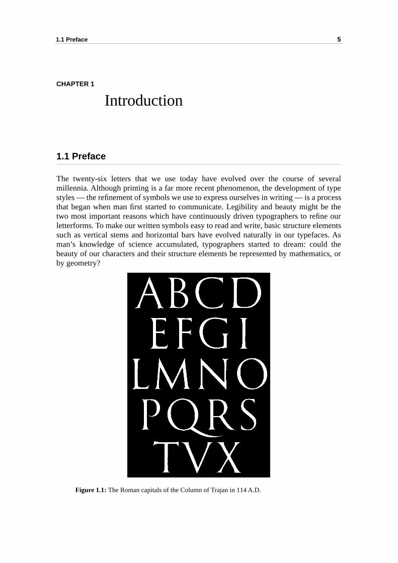
The twenty-six letters that we use today have evolved over the course of smillennia. Although printing is a far more recent phenomenon, the development ostyles — the refinement of symbols we use to express ourselves in writing — is a pthat began when man first started to communicate. Legibility and beauty might btwo most important reasons which have continuously driven typographers to refinletterforms. To make our written symbols easy to read and write, basic structure elesuch as vertical stems and horizontal bars have evolved naturally in our typefacman’s knowledge of science accumulated, typographers started to dream: coubeauty of our characters and their structure elements be represented by mathemby geometry?
Figure 1.1: The Roman capitals of the Column of Trajan in 114 A.D.
6
Chapter 1: Introduction
to the ownolumn 1.1). weresually foundn. By
stoneselled.m the
he oldl rulesmetry werer andeenthed byreo in
heighttting ofs and
pplypes ofaithfully
Perhaps the closest direct ancestor of our letterform can be dated back ancient Roman Empire. The most important contribution of the Romans to ouralphabet was the visual refinement of capital letters. The capitals incised in the Cof Trajan in 114 A.D. have been called the perfect expression of letters (Fig.“Indeed, they are the basis of all of our typefaces” [Labuz88, pp.31]. Roman lettersengraved with thick and thin strokes and graceful curves. Thicker strokes are ureferred to as major strokes; thinner stroke are minor strokes. Researchers havethat the tool required to produce these embellishments was a double-pointed peshifting the angle of the pen, the Roman could produce lines of any width. When awas to be carved, a sketch of the letter was first made with this tool and then chiYet the Roman capitals are not geometrically designed; their beauty comes frosubtleties of their curves and strokes.
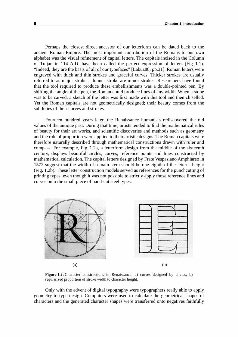
Fourteen hundred years later, the Renaissance humanists rediscovered tvalues of the antique past. During that time, artists tended to find the mathematicaof beauty for their art works, and scientific discoveries and methods such as geoand the rule of proportion were applied to their artistic designs. The Roman capitalstherefore naturally described through mathematical constructions drawn with rulecompass. For example, Fig. 1.2a, a letterform design from the middle of the sixtcentury, displays beautiful circles, curves, reference points and lines constructmathematical calculation. The capital letters designed by Frate Vespasiano Amphia1572 suggest that the width of a main stem should be one eighth of the letter’s (Fig. 1.2b). These letter construction models served as references for the punchcuprinting types, even though it was not possible to strictly apply those reference linecurves onto the small piece of hand-cut steel types.
Figure 1.2: Character constructions in Renaissance: a) curves designed by circles; b)regularized proportion of stroke width to character height.
Only with the advent of digital typography were typographers really able to ageometry to type design. Computers were used to calculate the geometrical shacharacters and the generated character shapes were transferred onto negatives f
(a) (b)
1.2 Previous work in font parametrization
7
s wereadays, fonts theapableet theation: could such as
ed orcters’ing yet
shapegital
s the
6a].rs ands and
nd penctions.
h thetafontSerifs the serifsed. Inr parts
le
dernso asge of
romanafont isquiresorldters
esign-
by digital laser photocomposer. New character design and representation methoddeveloped by the cooperation of typographers and computer scientists. Nowalmost every typesetting system produces characters by outlines. The outlinetechnology represents a character by its outline description and reproducecharacter’s image by a computer program called the font rasterizer. Outlines are cof describing the shape of a character either with straight lines or curved arcs, youtline representation lacks the ability to describe specific typographical informsuch as widths of strokes and the squareness of round parts. A problem came upwe design and represent characters so as to make sure that typographical featuresstroke width, serif length and squareness of round strokes could be controllmodified? Incorporating typographical information as parameters into the chararepresentation rather than describing characters by their contours — an interestdifficult problem — has attracted both typographers and computer scientists.
1.2 Previous work in font parametrization
The earliest attempt known to describe typographic characters by parametrizableprimitives was that of P. Coueignoux, who designed one of the first fully ditypesetter controllers [Coueignoux81].
The most serious published work done in the field of parametrizable fonts iMetafont system, a programmable parametrizable font synthesizing system [Knuth8The Metafont system relies on a few basic paradigms for generating charactesymbols. The main character parts such as horizontal, vertical, diagonal strokeround parts are specified by describing the path of a pen with given orientations awidths. The pen’s central path is described by a sequence of pen positions and direFrom this information, Metafont computes a smooth centerline pen trajectory. Witgiven pen positions, widths and orientations, and with the centerline trajectory, Meinfers the description of the boundary of the corresponding pen stroke [Hobby89]. with font dependent serif width, height and depth information are adjusted tocomputed stroke boundary. The shape boundary resulting from the assembly ofand stroke can either be directly filled, or traced by a small circular pen and then filladdition to strokes defined by pen trajectories, Metafont specifies round charactecovering one or multiple quadrants by superarcs, i.e. scaled arcs defined within a singquadrant whose boundaries are given by superellipses [Knuth86a, pp.126].
The Metafont program was used by Donald Knuth to create his Computer Motypeface family [Knuth86b]. The Computer Modern typefaces were parametrized to automatically generate optically scaled fonts and to generate by simple chanparametrization sans-serif, typewriter, semi-bold, bold, condensed and slanted fonts. Separate character shape descriptions are used for the italic font. Since Metboth a complete programming language and a flexible font design tool, using it reboth advanced programming and typographic skills. Only a few individuals in the ware known to use Metafont, often for the design of non-Latin charac[Haralambous94] [Southall98]. One of the lessons learned by users of Metafont d
8
Chapter 1: Introduction
om toxplainsly on
ased basicertical it ishich
strokesethod
uitedrs byFan91] whenor highll not
then toracterified.ch as, it istheiris notlines.ttingf the by
methoderiveposede partsly, ourbasic
ing Latin characters is that Metafont’s pen paradigm does not offer sufficient freedgenerate character shapes exactly according to the designer’s intention. This ewhy besides Computer Modern, most Metafont designs for Latin fonts rely heavioutline descriptions [Billawala89].
The recent Infinifont system [MacQueen93] [Bauermeister96] is a feature-bparametrizable font description and reconstruction system. Its authors describe themechanism to assemble a character such as character “E” from parametrizable vbars, horizontal bars and serifs. However, most of their work is not published andtherefore not known how they synthesize different typeface categories and wparadigms they use for synthesizing curved character shapes and serif variants.
Schneider describes a method for assembling parametrizable pen-based into typographic characters [Schneider98]. Regarding Latin character shapes, the msuffers from the same limitations as Metafont. It seems however particularly well sfor synthesizing Chinese characters. The method of assembling characteparametrizable strokes has already been tried for Chinese characters [Dong91] [[Dürst93]. Industrial implementation has shown that good results can be obtainedthe stroke-based Chinese characters are used for lower resolution applications. Fresolution applications, however, the quality of the reproduced characters is stisatisfying especially for connections and curved strokes.
Some researchers try to incorporate additional information (constraints) tooutline representation of characters [Shamir98] [Zalik95]. They use this informatioconstrain the relationship (distance or spatial order) between vertices of chaoutlines and, possibly, the moving directions of vertices when the outlines are modBy carefully specifying these point-to-point constraints, some typeface variations suvariation of boldness can be carried out. But, for more complex typeface variationsdifficult to predicate the behaviour of each contour point and thus to specify constraints. For example, for varying the contrast and oblique stress of a font, it sufficient to constrain the trajectory of some character contour points to straight Adding constraints to character outlines seems to be more suitable for grid-ficharacter outlines during the process of rasterization. For example, some oinstructions used in TrueType [Microsoft95a] fonts specify the grid-fitting methodconstraining the behaviour of character outline points.
1.3 Contents of this thesis
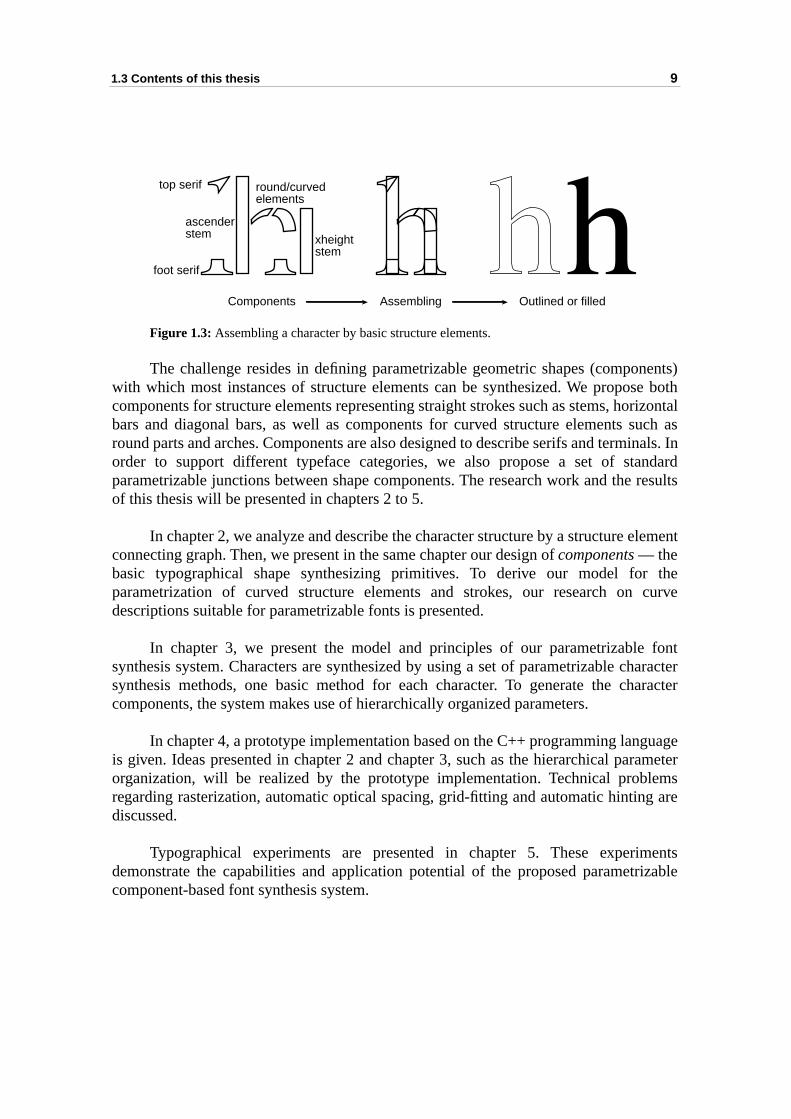
In this thesis, we propose a component-based parametrizable font representation and the implementation of its prototype. Traditional Latin letter shapes which dfrom Antiqua and Grotesque (sans-serif) typefaces [Tschichold65] can be decominto basic structure elements: vertical stems, round parts (also called curved shapor bowls), arches, horizontal bars, diagonal bars, serifs and terminals. Converseaim is to synthesize traditional letter shapes by coherently assembling such structure elements (Fig. 1.3).
1.3 Contents of this thesis
9
nents)e bothrizontaluch asinals. Inndard results
lement
thecurve
fontharacteraracter
guagerameterlemsg are
mentsrizable
Figure 1.3: Assembling a character by basic structure elements.
The challenge resides in defining parametrizable geometric shapes (compowith which most instances of structure elements can be synthesized. We proposcomponents for structure elements representing straight strokes such as stems, hobars and diagonal bars, as well as components for curved structure elements sround parts and arches. Components are also designed to describe serifs and termorder to support different typeface categories, we also propose a set of staparametrizable junctions between shape components. The research work and theof this thesis will be presented in chapters 2 to 5.
In chapter 2, we analyze and describe the character structure by a structure econnecting graph. Then, we present in the same chapter our design of components — thebasic typographical shape synthesizing primitives. To derive our model forparametrization of curved structure elements and strokes, our research on descriptions suitable for parametrizable fonts is presented.
In chapter 3, we present the model and principles of our parametrizablesynthesis system. Characters are synthesized by using a set of parametrizable csynthesis methods, one basic method for each character. To generate the chcomponents, the system makes use of hierarchically organized parameters.
In chapter 4, a prototype implementation based on the C++ programming lanis given. Ideas presented in chapter 2 and chapter 3, such as the hierarchical paorganization, will be realized by the prototype implementation. Technical probregarding rasterization, automatic optical spacing, grid-fitting and automatic hintindiscussed.
Typographical experiments are presented in chapter 5. These experidemonstrate the capabilities and application potential of the proposed parametcomponent-based font synthesis system.
Components Assembling Outlined or filled
top serif
foot serif
round/curvedelements
xheightstem
ascenderstem
10
Chapter 1: Introduction
inol-nsis-day’s
ext.
Ato be
ign.milyica
apers.aces. for aremous
andigitalining any
ctical
alle ofle
. Inor a
lyr (for
1.4 Terminology
In this thesis, traditional typographic terminology [Labuz88, pp.23-25] and the termogy used in digital typography will both be used. Sometimes, there is a little incotency between the traditional meaning of a term and its explanation according to tocomputer font technology. In such a case, the meaning should adapted to the cont
• A typeface is a distinctive design for a set of visually related symbols.typeface represents an abstract design idea for how letterforms are presented.
• A typeface family is a collection of typeface variations based on a single desFor example, Helvetica is a type style design. The Helvetica typeface famay contain Helvetica normal, Helvetica light, Helvetica bold, Helvetcondensed, Helvetica italic and other typefaces.
• This thesis focuses on text typefaces and not on decorative typefaces. Texttypefaces are used for the continuous setting of text in books and newspLegible, suitable and aesthetically pleasing letters are critical to text typefDecorative typefaces (mainly created in the 19th century) are useddecoration purposes in which attractiveness, novelty and loudnessemphasized. The distinction between them can be found in Rockledge’s faTypefinder system [Rockledge91].
• A font is a particular example of a typeface, traditionally in a particular size,contains symbols for each element of a particular character set. In dtypography, since outline fonts are scalable, a font is often a file contadescription data for shapes of all characters which can be scaled toparticular size by computer programs. It seems that there is no pradifference between a scalable digital font and a typeface.
• A parametrizable font is a font with parameters controlling typographicfeatures. Not only the size of a character is scalable, but also the stycharacters can be varied. By changing certain parameters, a parametrizabfontmay generate all typefaces or scalable fonts in a typeface family.
• A glyph is an individual symbol which appears when it has been printeddigital typography, a glyph is represented either in the form of an outline bitmapped image (array of dots) that is to be displayed or printed.
• A character synthesis method is a C++ object member function specialconceived for the typeface-independent generation of a given characteexample ASCII character “m”).
2.1 Structure of characters
11
basic
en
eibe theractersbe thesigned
ade ofal bars,Nowa-oesn’t spa-harac-. This
CHAPTER 2
Structures and components
In out font parametrization method, a character is constructed by pieces of descriptive shapes, called components. Components are connected to or placed betweeach other according to a structure graph which describe their relationship, i.e. thcharacter structure. The structure graph is a conceptual model used to descrcomponent decomposition of characters and, conversely, the assembling of chafrom their components. In this chapter, we first present our methodology to descristructure of characters. Then we will introduce the basic components we have deand our method to parametrize components.
2.1 Structure of characters
2.1.1 Character structure
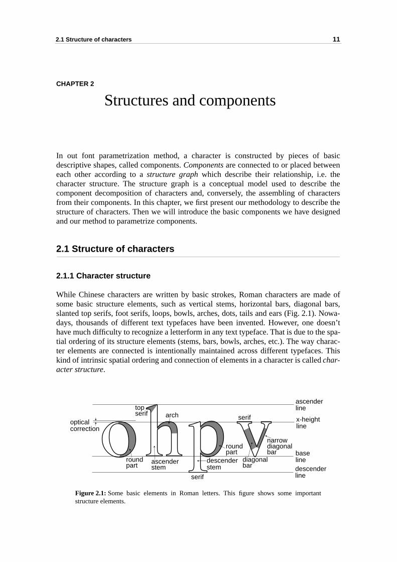
While Chinese characters are written by basic strokes, Roman characters are msome basic structure elements, such as vertical stems, horizontal bars, diagonslanted top serifs, foot serifs, loops, bowls, arches, dots, tails and ears (Fig. 2.1). days, thousands of different text typefaces have been invented. However, one dhave much difficulty to recognize a letterform in any text typeface. That is due to thetial ordering of its structure elements (stems, bars, bowls, arches, etc.). The way cter elements are connected is intentionally maintained across different typefaceskind of intrinsic spatial ordering and connection of elements in a character is calledchar-acter structure.
Figure 2.1: Some basic elements in Roman letters. This figure shows some importantstructure elements.
opticalcorrection
arch
roundpart
ascenderstem
roundpart
diagonalbar
narrowdiagonalbar
descenderstem
ascenderline
x-heightline
baselinedescenderline
topserif
serif
serif
12
Chapter 2: Structures and components
nitione rela-racters edgestween graphormaleletoneptual
er fornts by
sed inturestracks, wens areflesh.acterline ofleton?ectionhapeed and
ouldr, and
cter isembled
ctions.tems,ed byonentspatialns. A or be. The
Previous work on character structure focused on character and feature recogas well as character synthesis. C. H. Cox III and his colleagues [Cox82] studied thtionship between two aspects of characters: the embellishments of physical chaand the skeleton of letters. The basic elements of skeletons are (1) vertices, (2)which specify the spatial ordering between vertices, and (3) the relationships bevertices and edges. An extension of the symbolic representation commonly used intheory was employed to depict skeletons, which made it possible to do some fgraph analysis. Readers are referred to [Cox82] for a detailed description of the skmodel. As an application, the skeleton model was used to bridge between the concdescription of a letterform and the corresponding physical embellished charactcharacter recognition. Cox et al. have also proposed a way to create different foapplying different stroke definitions to their skeleton model.
The idea of using a skeleton to represent the character structure is also uother frameworks for different purposes, such as finding typographical fea[Herz97], creating thin line or skeleton fonts [Gonczarowski98], and describing the of a pen [Knuth86a]. However, for the sole purpose of building parametrizable fontfound the skeleton representation to have some disadvantages. Firstly, skeletosuitable for describing the bones of characters, but not for describing their Secondly, according to the typographer’s point of view, the meaning of a charskeleton is not very clearly defined. It is often assumed that the skeleton is the mida character. Should midlines of embellishments such as serifs be parts of the skeCox’s work is a good abstraction which puts emphasis on the relationship and connof “vertices”. It might be suitable for letterform shape analysis. But for character sgeneration, the typographical meanings of the vertices and edges are not definhence, not suitable for synthesizing parametrizable fonts.
The description of character structure for high-fidelity font parametrization shbe capable of (1) describing the essential ordering of different parts in a characte(2) refining the shape of the parts and their connection types.
2.1.2 Structure element connecting graph
We use the term structure element connecting graph, or structure graph, to describecharacter structures. The purpose of a structure graph is to explain how a charadecomposed into structure elements and, how these structure elements are assinto a full blown character.
The symbols used in structure graphs are structure elements and conneStructure elements are typographically functional parts, such as vertical shorizontal bars, full or half loops, and serifs. Structure elements can be synthesizone or more components (see section 2.2 for a detailed description of compdesign). The order of structure elements in a structure graph reflects the natural ordering of the corresponding parts in a character, but not their physical positiostructure element can either be connected to one or to more structure elementssimply isolated. If two structure elements connect, a line is drawn connecting them
2.1 Structure of characters
13
or by
traight
lanted
ps,e mainhapes,
androkes,
f thebstract oftenssed in
lines.
ardspped to The
connection of two structure elements will be implemented by means of operationsa special connecting component (to be discussed later).
2.1.2.1 Basic structure elements in structure graphs
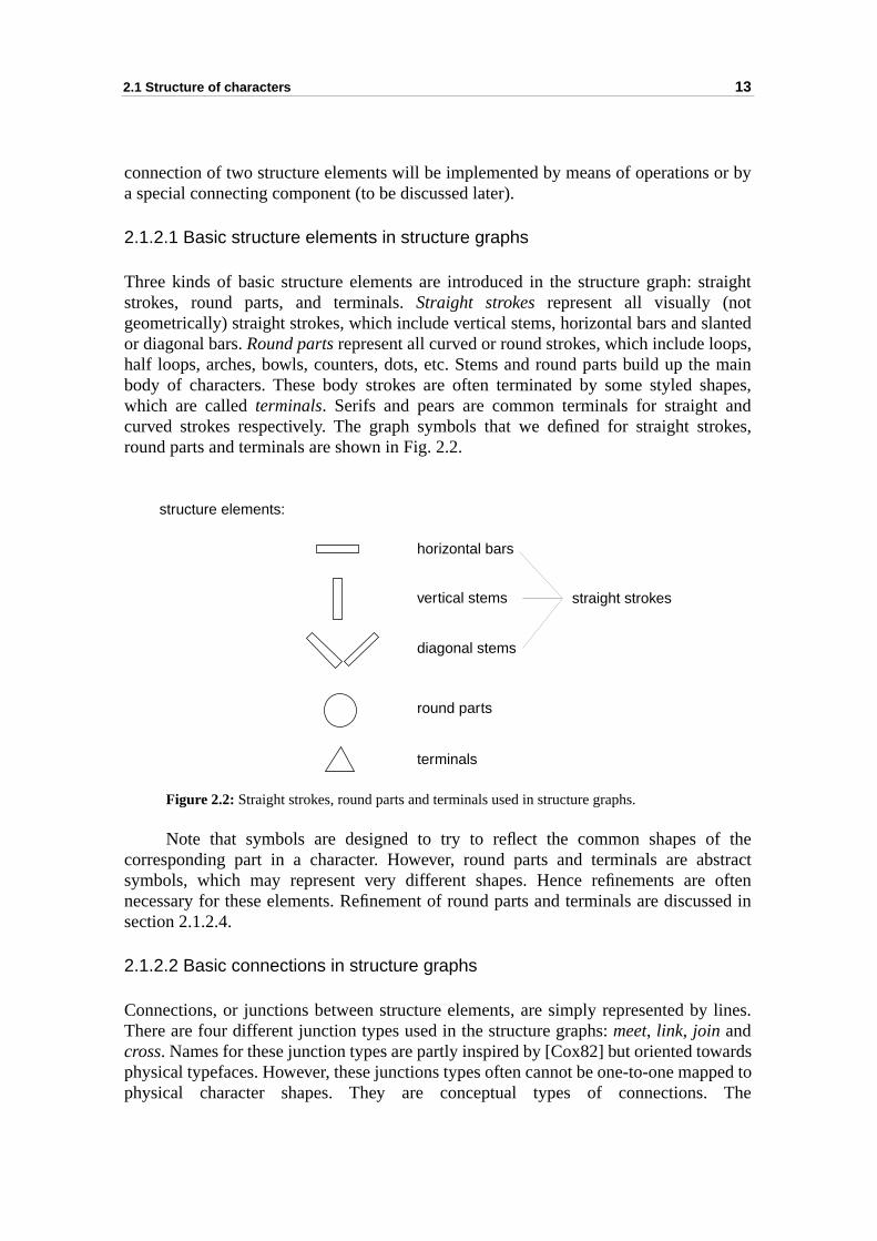
Three kinds of basic structure elements are introduced in the structure graph: sstrokes, round parts, and terminals. Straight strokes represent all visually (notgeometrically) straight strokes, which include vertical stems, horizontal bars and sor diagonal bars. Round parts represent all curved or round strokes, which include loohalf loops, arches, bowls, counters, dots, etc. Stems and round parts build up thbody of characters. These body strokes are often terminated by some styled swhich are called terminals. Serifs and pears are common terminals for straight curved strokes respectively. The graph symbols that we defined for straight stround parts and terminals are shown in Fig. 2.2.
Figure 2.2: Straight strokes, round parts and terminals used in structure graphs.
Note that symbols are designed to try to reflect the common shapes ocorresponding part in a character. However, round parts and terminals are asymbols, which may represent very different shapes. Hence refinements arenecessary for these elements. Refinement of round parts and terminals are discusection 2.1.2.4.
2.1.2.2 Basic connections in structure graphs
Connections, or junctions between structure elements, are simply represented byThere are four different junction types used in the structure graphs: meet, link, join andcross. Names for these junction types are partly inspired by [Cox82] but oriented towphysical typefaces. However, these junctions types often cannot be one-to-one maphysical character shapes. They are conceptual types of connections.
horizontal bars
vertical stems
diagonal stems
round parts
terminals
structure elements:
straight strokes
14
Chapter 2: Structures and components
ans of
their
The
n archph, the
Both very
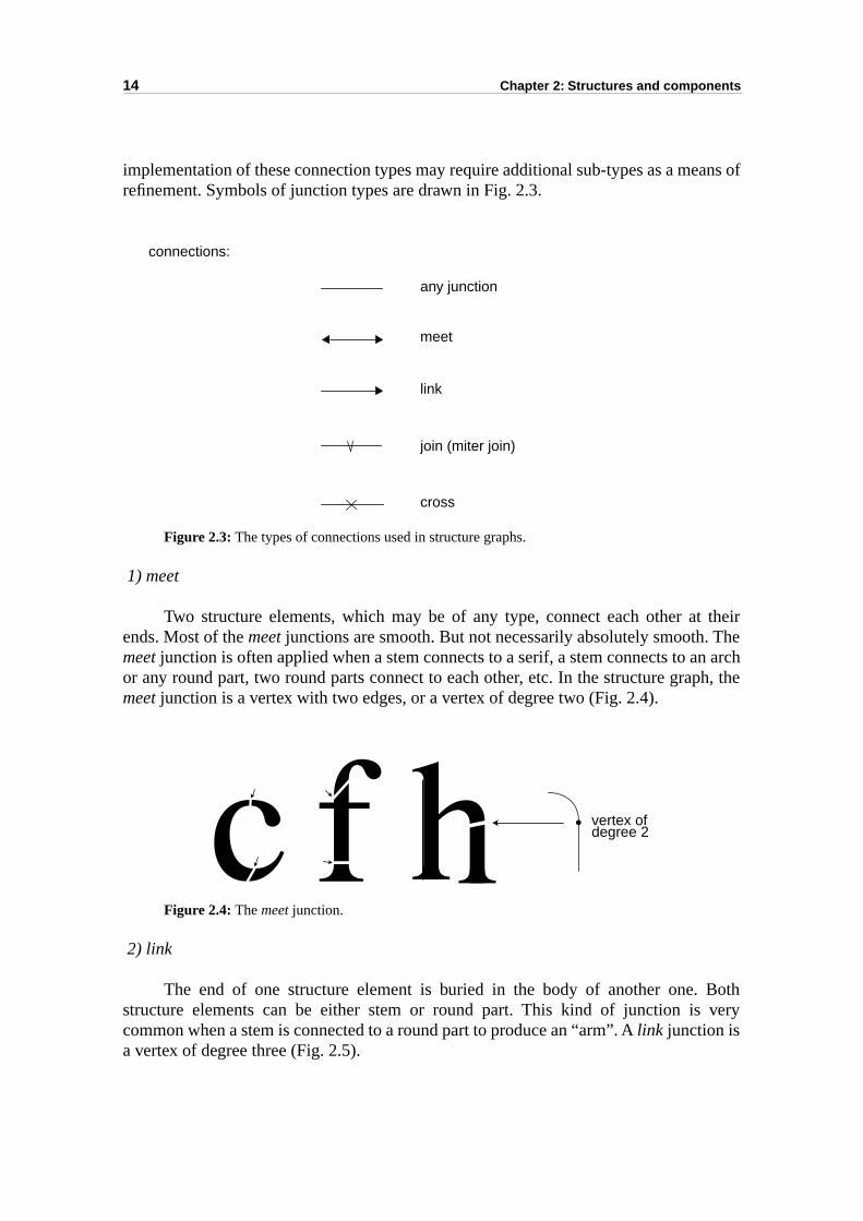
implementation of these connection types may require additional sub-types as a merefinement. Symbols of junction types are drawn in Fig. 2.3.
Figure 2.3: The types of connections used in structure graphs.
1) meet
Two structure elements, which may be of any type, connect each other atends. Most of the meet junctions are smooth. But not necessarily absolutely smooth.meet junction is often applied when a stem connects to a serif, a stem connects to aor any round part, two round parts connect to each other, etc. In the structure grameet junction is a vertex with two edges, or a vertex of degree two (Fig. 2.4).
Figure 2.4: The meet junction.
2) link
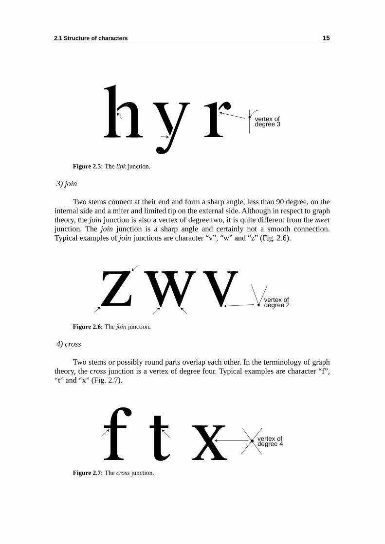
The end of one structure element is buried in the body of another one. structure elements can be either stem or round part. This kind of junction iscommon when a stem is connected to a round part to produce an “arm”. A link junction isa vertex of degree three (Fig. 2.5).
any junction
meet
link
cross
join (miter join)
connections:
vertex ofdegree 2
2.1 Structure of characters
15
, on thegraph
tion.
raph “f”,
Figure 2.5: The link junction.
3) join
Two stems connect at their end and form a sharp angle, less than 90 degreeinternal side and a miter and limited tip on the external side. Although in respect to theory, the join junction is also a vertex of degree two, it is quite different from the meetjunction. The join junction is a sharp angle and certainly not a smooth connecTypical examples of join junctions are character “v”, “w” and “z” (Fig. 2.6).
Figure 2.6: The join junction.
4) cross
Two stems or possibly round parts overlap each other. In the terminology of gtheory, the cross junction is a vertex of degree four. Typical examples are character“t” and “x” (Fig. 2.7).
Figure 2.7: The cross junction.
vertex ofdegree 3
vertex ofdegree 2
vertex ofdegree 4
16 Chapter 2: Structures and components
er tocribe acters, need
y theructurements
ring thean be
e oftennull tohs are
efined. corre-
sed to
ponent.nents.eeps
2.1.2.3 Design of structure graphs
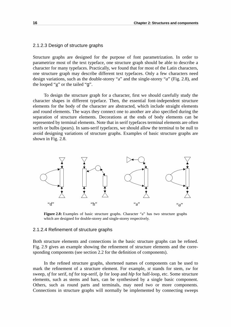
Structure graphs are designed for the purpose of font parametrization. In ordparametrize most of the text typeface, one structure graph should be able to descharacter for many typefaces. Practically, we found that for most of the Latin charaone structure graph may describe different text typefaces. Only a few charactersdesign variations, such as the double-storey “a” and the single-storey “a” (Fig. 2.8), andthe looped “g” or the tailed “g”.
To design the structure graph for a character, first we should carefully studcharacter shapes in different typeface. Then, the essential font-independent stelements for the body of the character are abstracted, which include straight eleand round elements. The ways they connect one to another are also specified duseparation of structure elements. Decorations at the ends of body elements crepresented by terminal elements. Note that in serif typefaces terminal elements arserifs or bulbs (pears). In sans-serif typefaces, we should allow the terminal to be avoid designing variations of structure graphs. Examples of basic structure grapshown in Fig. 2.8.
Figure 2.8: Examples of basic structure graphs. Character “a” has two structure graphswhich are designed for double-storey and single-storey respectively.
2.1.2.4 Refinement of structure graphs
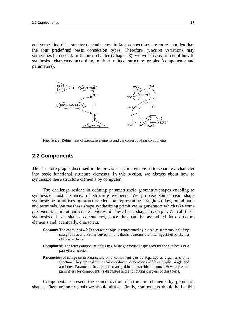
Both structure elements and connections in the basic structure graphs can be rFig. 2.9 gives an example showing the refinement of structure elements and thesponding components (see section 2.2 for the definition of components).
In the refined structure graphs, shortened names of components can be umark the refinement of a structure element. For example, st stands for stem, sw forsweep, sf for serif, tsf for top-serif, lp for loop and hlp for half-loop, etc. Some structureelements, such as stems and bars, can be synthesised by a single basic comOthers, such as round parts and terminals, may need two or more compoConnections in structure graphs will normally be implemented by connecting sw
“d” “h” “a” “a”
2.2 Components 17
x thanmayow to
ts and
haracterw to
ing to shape partse someeseure
inglist
f a
adare
etricflexible
and some kind of parameter dependencies. In fact, connections are more complethe four predefined basic connection types. Therefore, junction variations sometimes be needed. In the next chapter (Chapter 3), we will discuss in detail hsynthesize characters according to their refined structure graphs (componenparameters).
Figure 2.9: Refinement of structure elements and the corresponding components.
2.2 Components
The structure graphs discussed in the previous section enable us to separate a cinto basic functional structure elements. In this section, we discuss about hosynthesize these structure elements by computer.
The challenge resides in defining parametrizable geometric shapes enablsynthesize most instances of structure elements. We propose some basicsynthesizing primitives for structure elements representing straight strokes, roundand terminals. We see these shape synthesizing primitives as generators which takparameters as input and create contours of these basic shapes as output. We call thsynthesized basic shapes components, since they can be assembled into structelements and, eventually, characters.
Contour: The contour of a 2-D character shape is represented by pieces of segments includstraight lines and Bézier curves. In this thesis, contours are often specified by the of their vertices.
Component: The term component refers to a basic geometric shape used for the synthesis opart of a character.
Parameters of component: Parameters of a component can be regarded as arguments offunction. They are real values for coordinate, dimension (width or height), angle anattributes. Parameters in a font are managed in a hierarchical manner. How to prepparameters for components is discussed in the following chapters of this thesis.
Components represent the concretization of structure elements by geomshapes. There are some goals we should aim at. Firstly, components should be
sw1+sw2+sw3
sw4+sw5dot+path
st
sw6+sw7
sw5
sw1
sw2 sw3 sw6sw7
sw4
dot
st
path
18 Chapter 2: Structures and components
Theers. For curvee lessace, but
matterraightnt wesign of
y eitherto itsnt is a
ed byolutely have-evene stemameters of the
and intelligent enough to enable style coherent modifications of characters.synthesized shapes should response reasonably to a change of input parametexample, when the width at the horizontal extremum of a loop changes, the wholeshould also be adapted to maintain some curvature properties. Secondly, thparameters, the better. Reducing the number of parameters does not only save spalso simplifies the way to control, or tune, the shape of components.
2.2.1 Components for straight strokes
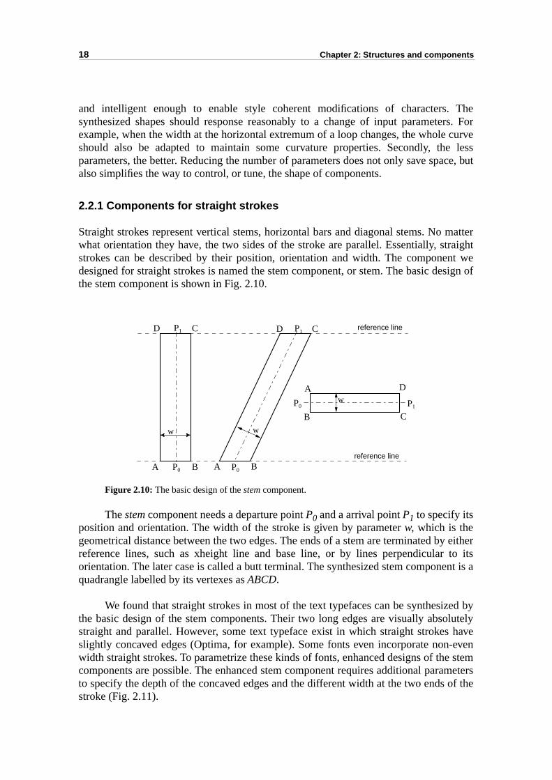
Straight strokes represent vertical stems, horizontal bars and diagonal stems. Nowhat orientation they have, the two sides of the stroke are parallel. Essentially, ststrokes can be described by their position, orientation and width. The componedesigned for straight strokes is named the stem component, or stem. The basic dethe stem component is shown in Fig. 2.10.
Figure 2.10: The basic design of the stem component.
The stem component needs a departure point P0 and a arrival point P1 to specify itsposition and orientation. The width of the stroke is given by parameter w, which is thegeometrical distance between the two edges. The ends of a stem are terminated breference lines, such as xheight line and base line, or by lines perpendicular orientation. The later case is called a butt terminal. The synthesized stem componequadrangle labelled by its vertexes as ABCD.
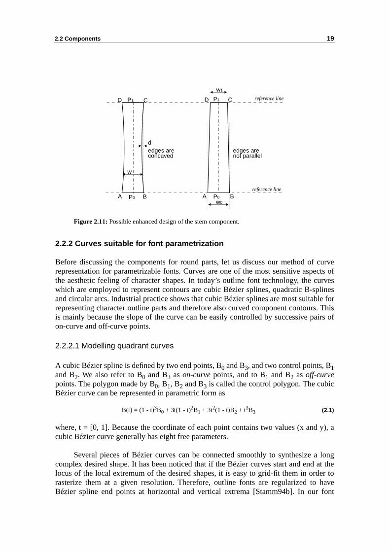
We found that straight strokes in most of the text typefaces can be synthesizthe basic design of the stem components. Their two long edges are visually absstraight and parallel. However, some text typeface exist in which straight strokesslightly concaved edges (Optima, for example). Some fonts even incorporate nonwidth straight strokes. To parametrize these kinds of fonts, enhanced designs of thcomponents are possible. The enhanced stem component requires additional parto specify the depth of the concaved edges and the different width at the two endsstroke (Fig. 2.11).
A B
D C
P0
P1
A
B
B
C
C
D
D
A
P0
P0
P1
P1
reference line
reference line
w w
w
2.2 Components 19
curveects of
curvesplinesble fors. Thisairs of
c
d y), a
a longd at theder to have font
Figure 2.11: Possible enhanced design of the stem component.
2.2.2 Curves suitable for font parametrization
Before discussing the components for round parts, let us discuss our method ofrepresentation for parametrizable fonts. Curves are one of the most sensitive aspthe aesthetic feeling of character shapes. In today’s outline font technology, the which are employed to represent contours are cubic Bézier splines, quadratic B-sand circular arcs. Industrial practice shows that cubic Bézier splines are most suitarepresenting character outline parts and therefore also curved component contouris mainly because the slope of the curve can be easily controlled by successive pon-curve and off-curve points.
2.2.2.1 Modelling quadrant curves
A cubic Bézier spline is defined by two end points, B0 and B3, and two control points, B1and B2. We also refer to B0 and B3 as on-curve points, and to B1 and B2 as off-curvepoints. The polygon made by B0, B1, B2 and B3 is called the control polygon. The cubiBézier curve can be represented in parametric form as
B(t) = (1 - t)3B0 + 3t(1 - t)2B1 + 3t2(1 - t)B2 + t3B3 (2.1)
where, t = [0, 1]. Because the coordinate of each point contains two values (x ancubic Bézier curve generally has eight free parameters.
Several pieces of Bézier curves can be connected smoothly to synthesize complex desired shape. It has been noticed that if the Bézier curves start and enlocus of the local extremum of the desired shapes, it is easy to grid-fit them in orrasterize them at a given resolution. Therefore, outline fonts are regularized toBézier spline end points at horizontal and vertical extrema [Stamm94b]. In our
A B
D C
P0
P1 reference line
reference line
w
A B
D C
P0
P1
w0
w1
dedges areconcaved
edges arenot parallel
20 Chapter 2: Structures and components
ents.drantt (foreters.
ve
eis to
an bee pick
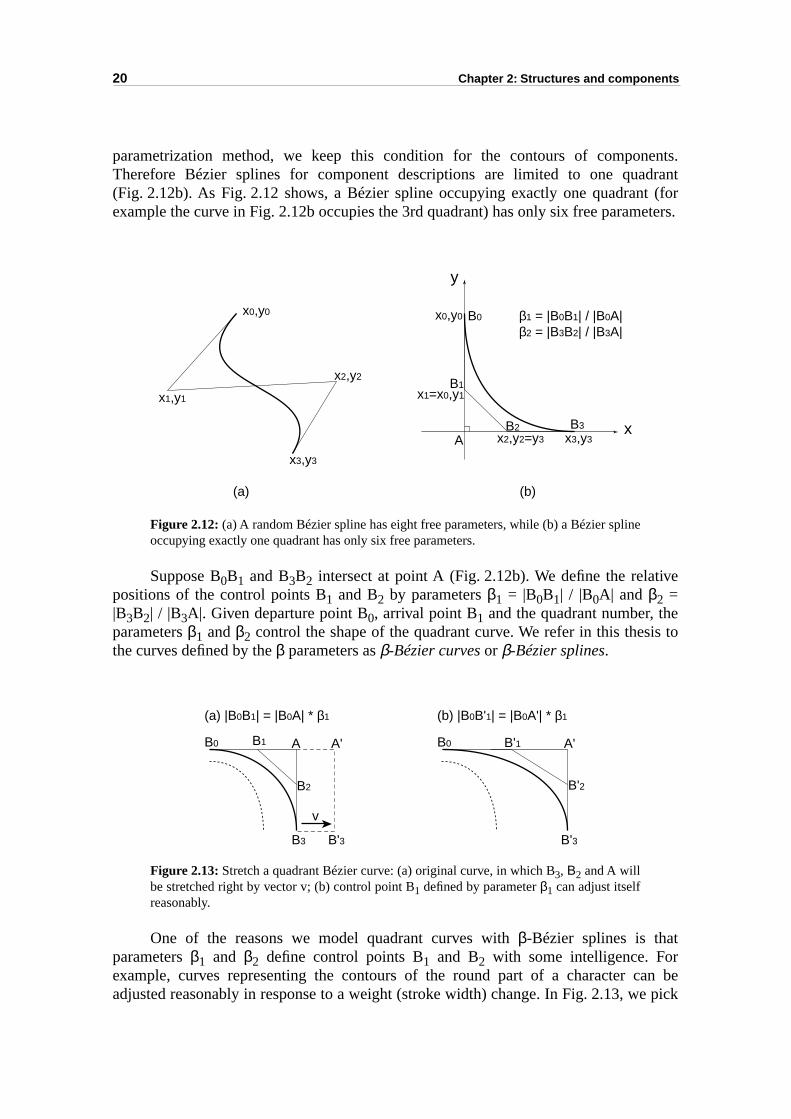
parametrization method, we keep this condition for the contours of componTherefore Bézier splines for component descriptions are limited to one qua(Fig. 2.12b). As Fig. 2.12 shows, a Bézier spline occupying exactly one quadranexample the curve in Fig. 2.12b occupies the 3rd quadrant) has only six free param
Figure 2.12: (a) A random Bézier spline has eight free parameters, while (b) a Bézier splineoccupying exactly one quadrant has only six free parameters.
Suppose B0B1 and B3B2 intersect at point A (Fig. 2.12b). We define the relatipositions of the control points B1 and B2 by parameters β1 = |B0B1| / |B0A| and β2 =|B3B2| / |B3A|. Given departure point B0, arrival point B1 and the quadrant number, thparameters β1 and β2 control the shape of the quadrant curve. We refer in this thesthe curves defined by the β parameters as β-Bézier curves or β-Bézier splines.
Figure 2.13: Stretch a quadrant Bézier curve: (a) original curve, in which B3, Β2 and A willbe stretched right by vector v; (b) control point B1 defined by parameter β1 can adjust itselfreasonably.
One of the reasons we model quadrant curves with β-Bézier splines is thatparameters β1 and β2 define control points B1 and B2 with some intelligence. Forexample, curves representing the contours of the round part of a character cadjusted reasonably in response to a weight (stroke width) change. In Fig. 2.13, w
x0,y0
x1,y1
x2,y2
x3,y3
x0,y0
x1=x0,y1
x2,y2=y3 x3,y3
B0
B1
B2 B3 x
y
A
(a) (b)
β1 = |B0B1| / |B0A|β2 = |B3B2| / |B3A|
B0 B1
B2 B'2
B3 B'3
A A' B0 B'1
B'3
A'
(a) |B0B1| = |B0A| * β1 (b) |B0B'1| = |B0A'| * β1
v
2.2 Components 21
” andh the
to the.1)
eriva-
Rough
cating
ng
e
a-plines
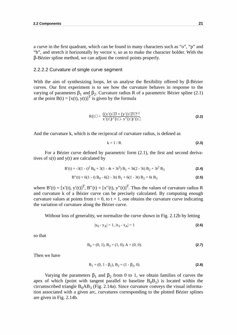
a curve in the first quadrant, which can be found in many characters such as “o”, “p“b”, and stretch it horizontally by vector v, so as to make the character bolder. Witβ-Bézier spline method, we can adjust the control points properly.
2.2.2.2 Curvature of single curve segment
With the aim of synthesizing loops, let us analyse the flexibility offered by β-Béziercurves. Our first experiment is to see how the curvature behaves in responsevarying of parameters β1 and β2. Curvature radius R of a parametric Bézier spline (2at the point B(t) = [x(t), y(t)]T is given by the formula
(2.2)
And the curvature k, which is the reciprocal of curvature radius, is defined as
k = 1 / R. (2.3)
For a Bézier curve defined by parametric form (2.1), the first and second dtives of x(t) and y(t) are calculated by
B′(t) = -3(1 - t)2 B0 + 3(1 - 4t + 3t2) B1 + 3t(2 - 3t) B2 + 3t2 B3 (2.4)
B′′ (t) = 6(1 - t) B0 - 6(2 - 3t) B1 + 6(1 - 3t) B2 + 6t B3 (2.5)
where B′(t) = [x′(t), y′(t)]T, B′′ (t) = [x′′ (t), y′′ (t)]T. Thus the values of curvature radius and curvature k of a Bézier curve can be precisely calculated. By computing encurvature values at points from t = 0, to t = 1, one obtains the curvature curve indithe variation of curvature along the Bézier curve.
Without loss of generality, we normalize the curve shown in Fig. 2.12b by letti
|y0 - yA| = 1, |x3 - xA| = 1 (2.6)
so that
B0 = (0, 1), B3 = (1, 0), A = (0, 0). (2.7)
Then we have
B1 = (0, 1 - β1), B2 = (1 - β2, 0). (2.8)
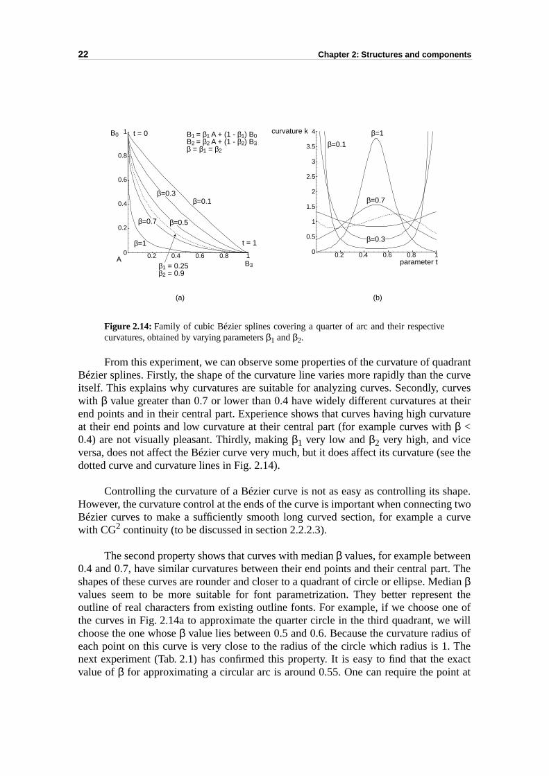
Varying the parameters β1 and β2 from 0 to 1, we obtain families of curves thapex of which (point with tangent parallel to baseline B0B1) is located within thecircumscribed triangle B0AB3 (Fig. 2.14a). Since curvature conveys the visual informtion associated with a given arc, curvatures corresponding to the plotted Bézier sare given in Fig. 2.14b.
R t( ) x ′ t( )( )2 y ′ t( )( )2+( )3 2/
x ′ t( )y″ t( ) x″ t( )y ′ t( )–-------------------------------------------------------=
22 Chapter 2: Structures and components
adrant curveurves theirvatureh
ee the
hape.g twocurve
nrt. Theedian nt thene ofe willus of. Theexact
int at
Figure 2.14: Family of cubic Bézier splines covering a quarter of arc and their respectivecurvatures, obtained by varying parameters β1 and β2.
From this experiment, we can observe some properties of the curvature of quBézier splines. Firstly, the shape of the curvature line varies more rapidly than theitself. This explains why curvatures are suitable for analyzing curves. Secondly, cwith β value greater than 0.7 or lower than 0.4 have widely different curvatures atend points and in their central part. Experience shows that curves having high curat their end points and low curvature at their central part (for example curves witβ <0.4) are not visually pleasant. Thirdly, making β1 very low and β2 very high, and viceversa, does not affect the Bézier curve very much, but it does affect its curvature (sdotted curve and curvature lines in Fig. 2.14).
Controlling the curvature of a Bézier curve is not as easy as controlling its sHowever, the curvature control at the ends of the curve is important when connectinBézier curves to make a sufficiently smooth long curved section, for example a with CG2 continuity (to be discussed in section 2.2.2.3).
The second property shows that curves with median β values, for example betwee0.4 and 0.7, have similar curvatures between their end points and their central pashapes of these curves are rounder and closer to a quadrant of circle or ellipse. Mβvalues seem to be more suitable for font parametrization. They better represeoutline of real characters from existing outline fonts. For example, if we choose othe curves in Fig. 2.14a to approximate the quarter circle in the third quadrant, wchoose the one whose β value lies between 0.5 and 0.6. Because the curvature radieach point on this curve is very close to the radius of the circle which radius is 1next experiment (Tab. 2.1) has confirmed this property. It is easy to find that the value of β for approximating a circular arc is around 0.55. One can require the po
0.2 0.4 0.6 0.8 10
0.5
1
1.5
2
2.5
3
3.5
4
0.2 0.4 0.6 0.8 10
0.2
0.4
0.6
0.8
1B0
B3A
curvature kB1 = β1 A + (1 - β1) B0B2 = β2 A + (1 - β2) B3β = β1 = β2
β=0.3β=0.7
β=0.3
β=0.5β=0.7
β=1
β=0.1
β=0.1
β=1
β1 = 0.25β2 = 0.9
t = 0
t = 1
parameter t
(a) (b)
2.2 Components 23
rter of
isnt
ave oneves.
faces
al ands,
ion with
f the
plinef theriginal
parameter t = 1/2 to have identical coordinates as the corresponding point of a quaa circle, by solving equation
(2.9)
where B(1/2) is the midpoint of the normalized Bézier curve B0B1B2B3 given inFig. 2.14a. Another criterion for finding the β value which approximates a circular arc requiring the curvature radius at B0 or B3 to be the radius of the arc. This requiremealso generates a β value around 0.55 (see Appendix A).
Our second experiment is concerned with the third property. Will one β value begood enough for the curves of character shapes? A positive answer enables us to sparameter and make it much easier to control the shape, or squareness, of the cur
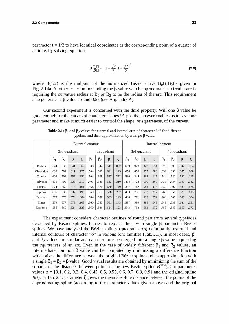
Table 2.1: β1 and β2 values for external and internal arcs of character “o” for different typeface and their approximation by a single β value.
The experiment considers character outlines of round part from several typedescribed by Bézier splines. It tries to replace them with single β parameter Béziersplines. We have analysed the Bézier splines (quadrant arcs) defining the externinternal contours of character “o” in various font families (Tab. 2.1). In most caseβ1and β2 values are similar and can therefore be merged into a single β value expressingthe squareness of an arc. Even in the case of widely different β1 and β2 values, anintermediate common β value can be computed by minimizing a difference functwhich gives the difference between the original Bézier spline and its approximationa single β1 = β2 = β value. Good visual results are obtained by minimizing the sum osquares of the distances between points of the new Bézier spline Bnew(u) at parametervalues u = {0.1, 0.2, 0.3, 0.4, 0.45, 0.5, 0.55, 0.6, 0.7, 0.8, 0.9} and the original sB(t). In Tab. 2.1, parameter ξ gives the mean absolute distance between the points oapproximating spline (according to the parameter values given above) and the o
External contour Internal contour
3rd quadrant 4th quadrant 3rd quadrant 4th quadrant
β1 β2 β ξ β1 β2 β ξ β1 β2 β ξ β1 β2 β ξ
Bodoni .544 .538 .541 .062 .538 .544 .541 .062 .699 .978 .842 .574 .978 .699 .842 .574
Clarendon .639 .584 .611 .125 .584 .639 .611 .125 .656 .659 .657 .088 .659 .656 .657 .088
Courier .609 .504 .557 .252 .504 .609 .557 .252 .580 .544 .562 .115 .544 .580 .562 .115
Helvetica .830 .405 .633 .310 .405 .830 .633 .310 .434 .728 .590 .360 .735 .434 .593 .342
Lucida .574 .660 .618 .161 .664 .574 .620 .149 .397 .742 .581 .475 .742 .397 .581 .475
Optima .606 .538 .537 .190 .660 .512 .588 .282 .483 .731 .613 .227 .760 .351 .571 .613
Palatino .573 .573 .573 .004 .584 .586 .585 .129 .430 .771 .612 .374 .700 .505 .607 .184
Times .579 .577 .578 .108 .560 .563 .561 .143 .597 .599 .598 .043 .643 .638 .641 .051
Universe .586 .660 .624 .123 .660 .586 .624 .123 .543 .753 .653 .072 .753 .543 .653 .072
B12---
1 22
-------– 1 22
-------–,T
=
24 Chapter 2: Structures and components
d
ur ofmes.
.
s andimilar,riginal
two orurveshe482].ity as
spline. In all cases, the mean absolute error distances ξ are very small when comparewith a typical capital letter height value of 800.
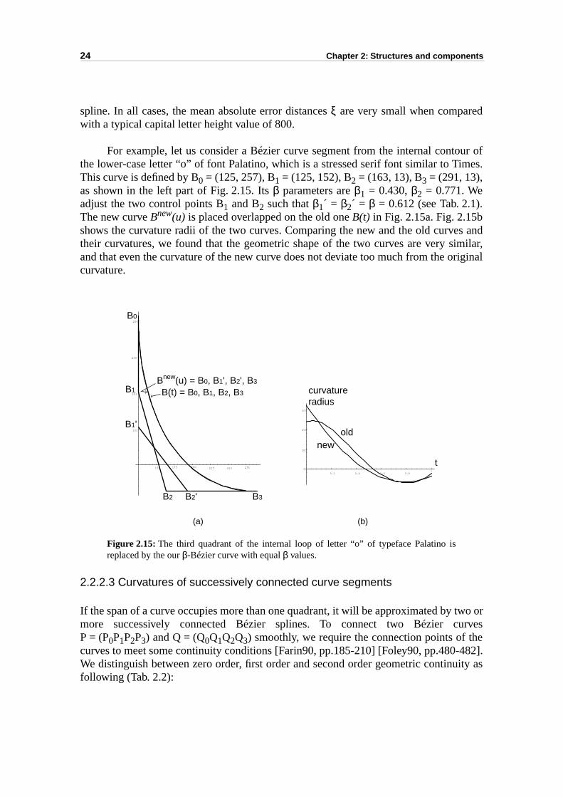
For example, let us consider a Bézier curve segment from the internal contothe lower-case letter “o” of font Palatino, which is a stressed serif font similar to TiThis curve is defined by B0 = (125, 257), B1 = (125, 152), B2 = (163, 13), B3 = (291, 13),as shown in the left part of Fig. 2.15. Its β parameters are β1 = 0.430, β2 = 0.771. Weadjust the two control points B1 and B2 such that β1´ = β2´ = β = 0.612 (see Tab. 2.1)The new curve Bnew(u) is placed overlapped on the old one B(t) in Fig. 2.15a. Fig. 2.15bshows the curvature radii of the two curves. Comparing the new and the old curvetheir curvatures, we found that the geometric shape of the two curves are very sand that even the curvature of the new curve does not deviate too much from the ocurvature.
Figure 2.15: The third quadrant of the internal loop of letter “o” of typeface Palatino isreplaced by the our β-Bézier curve with equal β values.
2.2.2.3 Curvatures of successively connected curve segments
If the span of a curve occupies more than one quadrant, it will be approximated by more successively connected Bézier splines. To connect two Bézier cP = (P0P1P2P3) and Q = (Q0Q1Q2Q3) smoothly, we require the connection points of tcurves to meet some continuity conditions [Farin90, pp.185-210] [Foley90, pp.480-We distinguish between zero order, first order and second order geometric continufollowing (Tab. 2.2):
150 175 200 225 250 275
100
150
200
250
B(t) = B0, B1, B2, B3
Bnew(u) = B0, B1', B2', B3
B0
B1
B2 B3
B1'
B2'
0.2 0.4 0.6 0.81
300
400
500
oldnew
curvatureradius
t
(a) (b)
2.2 Components 25
nr,ges of
e with
ézierende truendllipse
d as ahich ise best their
t the
fva-uset us same
Table 2.2: Conditions of geometric continuity of two connected Bézier curves.
It is easy to reach CG1 continuity, but the condition of CG2 continuity is not easy tomeet. Connecting two cubic Bézier curves with CG2 continuity results in a curvaturecontinuous yet not necessarily twice differentiable long curve. Currently, curves used ioutline fonts are only required to reach CG1 continuity at the connection point. Howevetypographers design round parts of characters as a whole curve. Sudden chancurvature along a curve are not intended. So, if we try to approximate the real curvpiecewise Bézier curves, we would like to keep the curvatures at P3 and Q0 as close aspossible, i.e. try to meet the condition of CG2 continuity.
From the discussion in the previous section (section 2.2.2.2), we know that Bcurves with median β parameters have curvatures which do not vary strongly from points to central part. If we connect two such β-Bézier splines, the curvatures at thconnection points will be more likely to be close to each other. This is obviouslywhen we connect four quadrant β-Bézier splines to approximate a circle. Since the roupart of characters are more like parts of an ellipse, we expect that the eapproximated by four quadrant β-Bézier splines has also a well behaving curvature.
Let us take a closer look at the curvature radius of an ellipse. Does the β value usedfor approximating a circle also work for an ellipse? Since an ellipse can be regardescaled circle, we expect that the scale transformation applied to the Bézier curve wthe best approximation of a quadrant circle will generate a Bézier curve which is thapproximation of a quadrant ellipse. This can be proved again by comparingcurvature radii. An ellipse can be presented in a parametric form
P(t) = {x(t) = a cos t, y(t) = b sin t, t ∈ [0, 2π]} (2.10)
where coefficient a is the half axis length in the x direction, coefficient b is the half axislength in the y direction. Using the example in Fig. 2.15, we have a = (x3 - x0) = 291-125= 166, b = (y0 - y3) = 257-13 = 244. From (2.2) and (2.10), the curvature radius apoint P(t) = (x(t), y(t)) is
R(t) = (a2 sin2 t + b2 cos2 t)3/2 / (a b) (2.11)
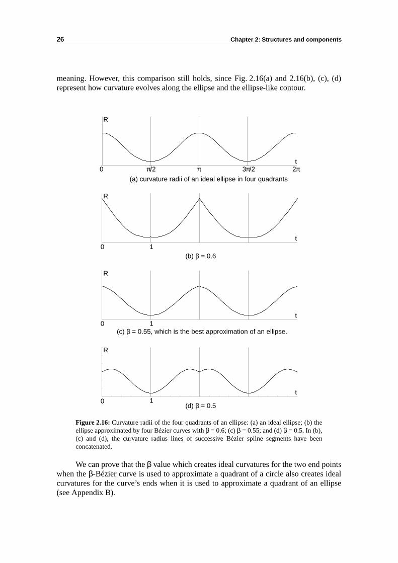
Fig. 2.16a shows the curvature radius for the ideal ellipse. Using β = 0.55, eachquadrant of the ellipse can be approximated by a β-Bézier curve. The curvature radius othe best approximating β-Bézier spline is shown in Fig. 2.16c. We also show two curture radii of parameter β = 0.6 and β = 0.5 (Fig. 2.16b, Fig. 2.16d). The curvature radifor β around 0.55 is the most similar to the curvature radius of an ideal ellipse. Lnotice that the parameter of an ellipse and a Bézier curve have not exactly the
Order of GC Conditions of Bézier curves P and Q
zero order (CG0) P3 = Q0.
first order (CG1) CG0 and tangent directions at P3 and Q0 are the same.
second order (CG2) CG1, normal vectors at P3 and Q3 have same direction, and curvatures at P3 and Q3 are identical.
26 Chapter 2: Structures and components
), (d)
ints idealellipse
meaning. However, this comparison still holds, since Fig. 2.16(a) and 2.16(b), (crepresent how curvature evolves along the ellipse and the ellipse-like contour.
Figure 2.16: Curvature radii of the four quadrants of an ellipse: (a) an ideal ellipse; (b) theellipse approximated by four Bézier curves with β = 0.6; (c) β = 0.55; and (d) β = 0.5. In (b),(c) and (d), the curvature radius lines of successive Bézier spline segments have beenconcatenated.
We can prove that the β value which creates ideal curvatures for the two end powhen the β-Bézier curve is used to approximate a quadrant of a circle also createscurvatures for the curve’s ends when it is used to approximate a quadrant of an (see Appendix B).
(a) curvature radii of an ideal ellipse in four quadrants
(b) β = 0.6
(c) β = 0.55, which is the best approximation of an ellipse.
(d) β = 0.5
π/2 π 3π/2 2π0
0 1
0 1
0 1
R
t
R
t
R
t
R
t
2.2 Components 27
éziernot maked fromound outerg end text
as
letters
ign ises areentrol
e has aod, a
ss than
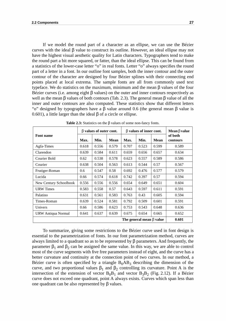
If we model the round part of a character as an ellipse, we can use the Bcurves with the ideal β value to construct its outline. However, an ideal ellipse may have the highest visual aesthetic quality for Latin characters. Typographers tend tothe round part a bit more squared, or fatter, than the ideal ellipse. This can be founa statistics of the lower-case letter “o” in real fonts. Letter “o” always specifies the rpart of a letter in a font. In our outline font samples, both the inner contour and thecontour of the character are designed by four Bézier splines with their connectinpoints placed at local extrema. The sample fonts are all from commonly usedtypeface. We do statistics on the maximum, minimum and the mean β values of the fourBézier curves (i.e. among eight β values) on the outer and inner contours respectivelywell as the mean β values of both contours (Tab. 2.3). The general mean β value of all theinner and outer contours are also computed. These statistics show that different“o” designed by typographers have a β value around 0.6 (the general mean β value is0.601), a little larger than the ideal β of a circle or ellipse.
To summarize, giving some restrictions to the Bézier curve used in font desessential to the parametrization of fonts. In our font parametrization method, curvalways limited to a quadrant so as to be represented by β parameters. And frequently, thparameter β1 and β2 can be assigned the same value. In this way, we are able to comost of the curve segments with five free parameters instead of eight, and the curvbetter curvature and continuity at the connection point of two curves. In our methBézier curve is often specified by a triangle B0AB3 describing the dimension of thecurve, and two proportional values β1 and β2 controlling its curvature. Point A is theintersection of the extension of vector B0B1 and vector B3B2 (Fig. 2.12). If a Béziercurve does not exceed one quadrant, point A always exists. Curves which span leone quadrant can be also represented by β values.
Table 2.3: Statistics on the β values of some non-fancy fonts.
Font nameβ values of outer cont. β values of inner cont. Mean β value
of both contoursMax. Min. Mean Max. Min. Mean
Agfa-Times 0.618 0.556 0.579 0.707 0.523 0.599 0.589
Clarendon 0.639 0.584 0.611 0.659 0.656 0.657 0.634
Courier Bold 0.62 0.538 0.578 0.623 0.557 0.589 0.586
Courier 0.638 0.504 0.563 0.613 0.544 0.57 0.567
Frutiger-Roman 0.6 0.547 0.58 0.692 0.476 0.577 0.579
Lucida 0.66 0.574 0.618 0.742 0.397 0.57 0.594
New Century Schoolbook 0.556 0.556 0.556 0.654 0.649 0.651 0.604
URW Times 0.583 0.558 0.57 0.643 0.597 0.611 0.591
Palatino 0.631 0.561 0.583 0.763 0.43 0.605 0.594
Times-Roman 0.639 0.524 0.581 0.792 0.509 0.601 0.591
Univers 0.66 0.586 0.623 0.753 0.543 0.648 0.636
URW Antiqua Normal 0.641 0.637 0.639 0.675 0.654 0.665 0.652
The general mean β value 0.601
28 Chapter 2: Structures and components
suchsed to
or ah arean be bebeingaracterightca “o”,uiret arcs
btains is notel the
2.2.3 Components for round parts
Round parts are synthesized by components named loop, half-loop and sweep. The loopand half-loop components aim at synthesizing ellipse-like round parts of charactersas the round parts in characters o, b, d, p, q, g. The sweep component is usynthesize any round stroke inscribed within one quadrant.
2.2.3.1 The loop component
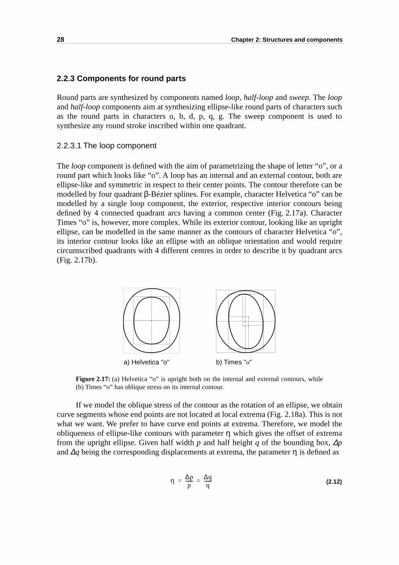
The loop component is defined with the aim of parametrizing the shape of letter “o”,round part which looks like “o”. A loop has an internal and an external contour, botellipse-like and symmetric in respect to their center points. The contour therefore cmodelled by four quadrant β-Bézier splines. For example, character Helvetica “o” canmodelled by a single loop component, the exterior, respective interior contours defined by 4 connected quadrant arcs having a common center (Fig. 2.17a). ChTimes “o” is, however, more complex. While its exterior contour, looking like an uprellipse, can be modelled in the same manner as the contours of character Helvetiits interior contour looks like an ellipse with an oblique orientation and would reqcircumscribed quadrants with 4 different centres in order to describe it by quadran(Fig. 2.17b).
Figure 2.17: (a) Helvetica “o” is upright both on the internal and external contours, while(b) Times “o” has oblique stress on its internal contour.
If we model the oblique stress of the contour as the rotation of an ellipse, we ocurve segments whose end points are not located at local extrema (Fig. 2.18a). Thiwhat we want. We prefer to have curve end points at extrema. Therefore, we modobliqueness of ellipse-like contours with parameter η which gives the offset of extremafrom the upright ellipse. Given half width p and half height q of the bounding box, ∆pand ∆q being the corresponding displacements at extrema, the parameter η is defined as
(2.12)
a) Helvetica "o" b) Times "o"
η ∆pp
-------= =
2.2 Components 29
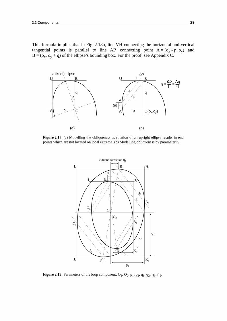
tical
This formula implies that in Fig. 2.18b, line VH connecting the horizontal and vertangential points is parallel to line AB connecting point A = (ox - p, oy) andB = (ox, oy + q) of the ellipse’s bounding box. For the proof, see Appendix C.Figure 2.18: (a) Modelling the obliqueness as rotation of an upright ellipse results in endpoints which are not located on local extrema. (b) Modelling obliqueness by parameter η.
Figure 2.19: Parameters of the loop component: O1, O2, p1, p2, q1, q2, η1, η2.
O(ox,oy)A
B
p
ql1
l2
∆p
∆q
η = — = —∆pp
V
HU
OA
B
p
q
U
θ
axis of ellipse
(a) (b)
O1
O2
A1
B1
C1
D1
H1I1
J1 K1
p1
q1
A2
B2
C2
D2
H2I2
J2 K2
exterme correction η1
l1
l2
p2
q2
η2
30 Chapter 2: Structures and components
lated.nt are:
theiran bengles
e of loopsnt
loop
r right) oflf-loopit is.ttomr, theby its
Given the center of an ellipse-like contour, the half width p and half height q of thebounding box, the contour’s location, dimension and bounding box can be calcuThe parameters of the external contour and the internal contour of a loop componethe center points O1 and O2, the half width of bonding box p1 and p2, the half height ofthe bounding box q1 and q2, and the extrema correction parameters η1 and η2. Note that,both the internal and the external ellipse-like contours are symmetric in respect torespective center points. Hence, the four quadrants of the loop component cgenerated (Fig. 2.19). We label the external contour by four successive control triaof β-Bézier curves (A1H1B1, B1I1C1, C1J1D1, D1K1A1) in counterclockwise orientation(positive orientation), and label the internal contour as (A2K2D2, D2J2C2, C2I2B2,B2H2A2) in clockwise orientation (negative orientation).
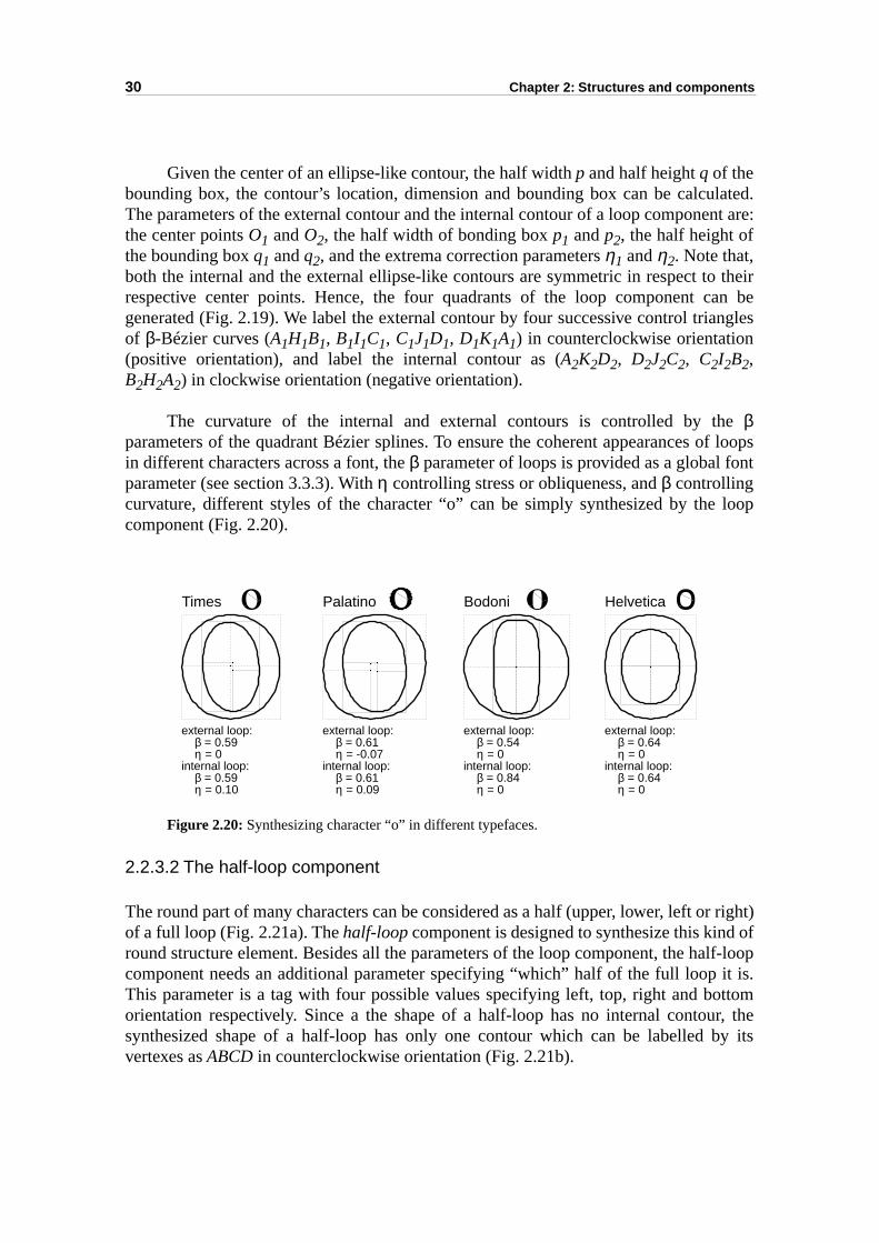
The curvature of the internal and external contours is controlled by thβparameters of the quadrant Bézier splines. To ensure the coherent appearances in different characters across a font, the β parameter of loops is provided as a global foparameter (see section 3.3.3). With η controlling stress or obliqueness, and β controllingcurvature, different styles of the character “o” can be simply synthesized by thecomponent (Fig. 2.20).
Figure 2.20: Synthesizing character “o” in different typefaces.
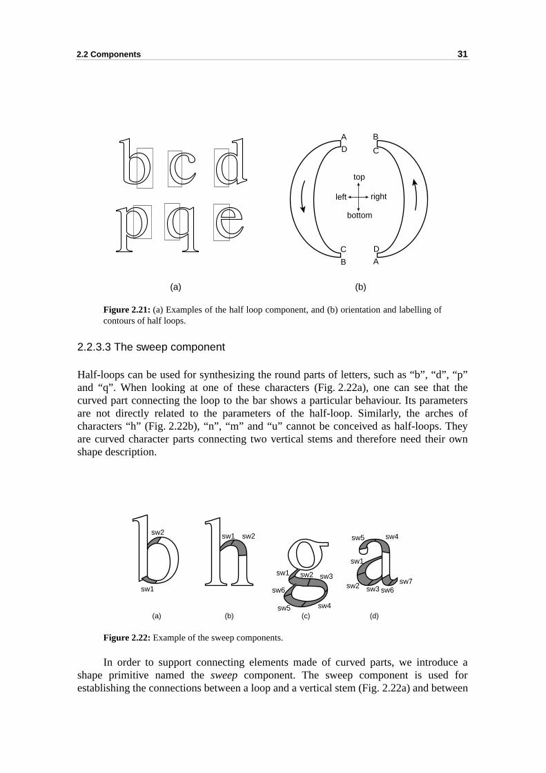
2.2.3.2 The half-loop component
The round part of many characters can be considered as a half (upper, lower, left oof a full loop (Fig. 2.21a). The half-loop component is designed to synthesize this kindround structure element. Besides all the parameters of the loop component, the hacomponent needs an additional parameter specifying “which” half of the full loop This parameter is a tag with four possible values specifying left, top, right and boorientation respectively. Since a the shape of a half-loop has no internal contousynthesized shape of a half-loop has only one contour which can be labelled vertexes as ABCD in counterclockwise orientation (Fig. 2.21b).
Times
external loop: β = 0.59 η = 0internal loop: β = 0.59 η = 0.10
Palatino
external loop: β = 0.61 η = -0.07internal loop: β = 0.61 η = 0.09
Bodoni
external loop: β = 0.54 η = 0internal loop: β = 0.84 η = 0
Helvetica
external loop: β = 0.64 η = 0internal loop: β = 0.64 η = 0
2.2 Components 31
”, “p”at the
meterses ofheyir own
uce aforetween
Figure 2.21: (a) Examples of the half loop component, and (b) orientation and labelling ofcontours of half loops.
2.2.3.3 The sweep component
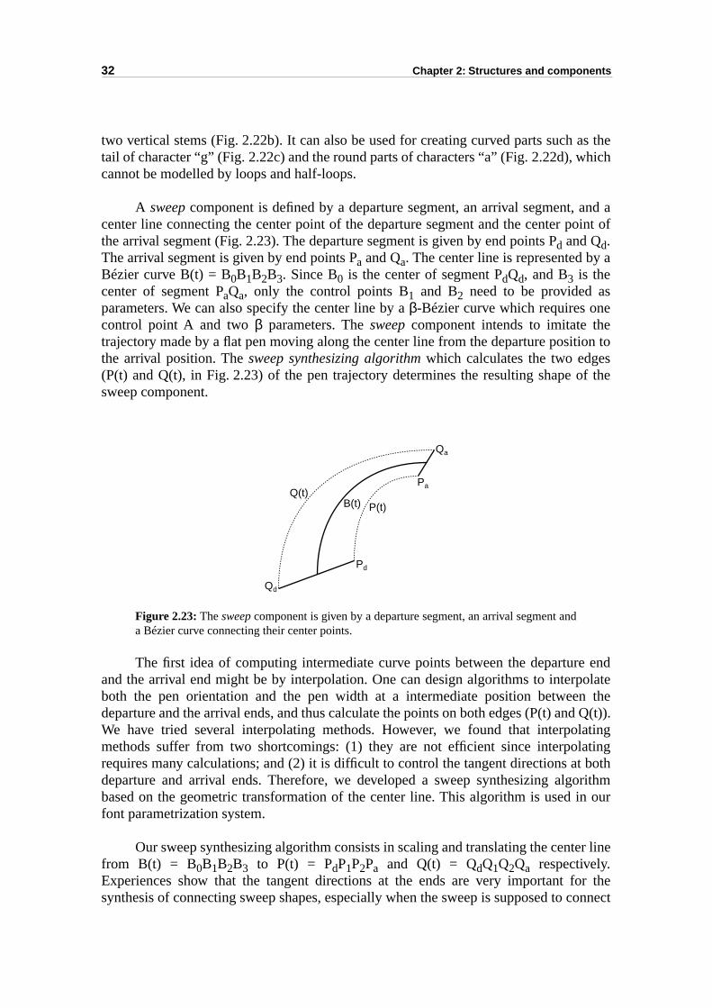
Half-loops can be used for synthesizing the round parts of letters, such as “b”, “dand “q”. When looking at one of these characters (Fig. 2.22a), one can see thcurved part connecting the loop to the bar shows a particular behaviour. Its paraare not directly related to the parameters of the half-loop. Similarly, the archcharacters “h” (Fig. 2.22b), “n”, “m” and “u” cannot be conceived as half-loops. Tare curved character parts connecting two vertical stems and therefore need theshape description.
Figure 2.22: Example of the sweep components.
In order to support connecting elements made of curved parts, we introdshape primitive named the sweep component. The sweep component is used establishing the connections between a loop and a vertical stem (Fig. 2.22a) and b
A
B
C
D
A
B
C
D
top
bottom
rightleft
(a) (b)
sw2
sw1
sw1 sw2
sw1 sw2 sw3
sw4sw5
sw6
sw5 sw4
sw1
sw2 sw3 sw6sw7
(a) (b) (c) (d)
32 Chapter 2: Structures and components
as thehich
and aoint of
a
eion tosof the
e endolaten thed Q(t)).atingating bothorithmin our
r line
or the connect
two vertical stems (Fig. 2.22b). It can also be used for creating curved parts suchtail of character “g” (Fig. 2.22c) and the round parts of characters “a” (Fig. 2.22d), wcannot be modelled by loops and half-loops.
A sweep component is defined by a departure segment, an arrival segment, center line connecting the center point of the departure segment and the center pthe arrival segment (Fig. 2.23). The departure segment is given by end points Pd and Qd.The arrival segment is given by end points Pa and Qa. The center line is represented byBézier curve B(t) = B0B1B2B3. Since B0 is the center of segment PdQd, and B3 is thecenter of segment PaQa, only the control points B1 and B2 need to be provided asparameters. We can also specify the center line by a β-Bézier curve which requires onecontrol point A and two β parameters. The sweep component intends to imitate thtrajectory made by a flat pen moving along the center line from the departure positthe arrival position. The sweep synthesizing algorithm which calculates the two edge(P(t) and Q(t), in Fig. 2.23) of the pen trajectory determines the resulting shape sweep component.
Figure 2.23: The sweep component is given by a departure segment, an arrival segment anda Bézier curve connecting their center points.
The first idea of computing intermediate curve points between the departurand the arrival end might be by interpolation. One can design algorithms to interpboth the pen orientation and the pen width at a intermediate position betweedeparture and the arrival ends, and thus calculate the points on both edges (P(t) anWe have tried several interpolating methods. However, we found that interpolmethods suffer from two shortcomings: (1) they are not efficient since interpolrequires many calculations; and (2) it is difficult to control the tangent directions atdeparture and arrival ends. Therefore, we developed a sweep synthesizing algbased on the geometric transformation of the center line. This algorithm is used font parametrization system.
Our sweep synthesizing algorithm consists in scaling and translating the centefrom B(t) = B0B1B2B3 to P(t) = PdP1P2Pa and Q(t) = QdQ1Q2Qa respectively.Experiences show that the tangent directions at the ends are very important fsynthesis of connecting sweep shapes, especially when the sweep is supposed to
Pd
Pa
Qd
Qa
P(t)Q(t)
B(t)
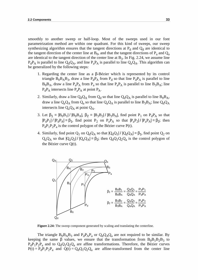
2.2 Components 33
fontweep
ol
y
vese
smoothly to another sweep or half-loop. Most of the sweeps used in our parametrization method are within one quadrant. For this kind of sweeps, our ssynthesizing algorithm ensures that the tangent directions at Pd and Qd are identical tothe tangent direction of the center line at B0, and that the tangent directions of Pa and Qaare identical to the tangent direction of the center line at B3. In Fig. 2.24, we assume linePdPA is parallel to line QdQA, and line PaPA is parallel to line QaQA. This algorithm canbe generalized by the following steps:
1. Regarding the center line as a β-Bézier which is represented by its contrtriangle B0BAB3, draw a line PdPA from Pd so that line PdPA is parallel to lineB0BA, draw a line PaPA from Pa so that line PaPA is parallel to line B3BA; linePdPA intersects line PaPA at point PA.
2. Similarly, draw a line QdQA from Qd so that line QdQA is parallel to line B0BA,draw a line QaQA from Qa so that line QaQA is parallel to line B3BA; line QdQAintersects line QaQA at point QA.
3. Let β1 = |B0B1| / |B0BA|, β2 = |B3B2| / |B3BA|, find point P1 on PdPA so that|PdP1| / |PdPA| = β1, find point P2 on PaPA so that |PaP2| / |PaPA| = β2; thenPdP1P2Pa is the control polygon of the Bézier curve P(t).
4. Similarly, find point Q1 on QdQA so that |QdQ1| / |QdQA| = β1, find point Q2 onQaQA so that |QaQ2| / |QaQA| = β2; then QdQ1Q2Qa is the control polygon ofthe Bézier curve Q(t).
Figure 2.24: The sweep component generated by scaling and translating the centerline.
The triangle B0BAB3 and PdPAPa or QdQAQa are not required to be similar. Bkeeping the same β values, we ensure that the transformation from B0B1B2B3 toPdP1P2Pa and to QdQ1Q2Qa are affine transformations. Therefore, the Bézier curP(t) = PdP1P2Pa and Q(t) = QdQ1Q2Qa are affine-transformed from the center lin
Qd
B0
Pd
B1
B2B3
Pa
Qa
P1
P2
Q1
Q2QA
BA
PA
β1 = =B0B1
B0BA=
QdQ1
QdQA
PdP1
PdPA
β2 = =B3B2
B3BA=
QaQ2
QaQA
PaP2
PaPA
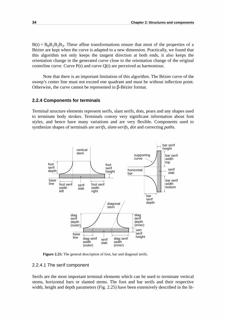
34 Chapter 2: Structures and components
of ad thats theriginal
f the point.
es usedfont
sed to
erticalective
the lit-
B(t) = B0B1B2B3. These affine transformations ensure that most of the propertiesBézier are kept when the curve is adapted to a new dimension. Practically, we founthis algorithm not only keeps the tangent direction at both ends, it also keeporientation change in the generated curve close to the orientation change of the ocenterline curve. Curve P(t) and curve Q(t) are perceived as harmonious.
Note that there is an important limitation of this algorithm. The Bézier curve osweep’s center line must not exceed one quadrant and must be without inflectionOtherwise, the curve cannot be represented in β-Bézier format.
2.2.4 Components for terminals
Terminal structure elements represent serifs, slant serifs, dots, pears and any shapto terminate body strokes. Terminals convey very significant information about styles, and hence have many variations and are very flexible. Components usynthesize shapes of terminals are serifs, slant-serifs, dot and correcting paths.
Figure 2.25: The general description of foot, bar and diagonal serifs.
2.2.4.1 The serif component
Serifs are the most important terminal elements which can be used to terminate vstems, horizontal bars or slanted stems. The foot and bar serifs and their respwidth, height and depth parameters (Fig. 2.25) have been extensively described in
foot serifwidthleft
foot serifwidthright
footserif height
footserifdepth
verticalstem
baseline
bar serifwidthtop
bar serifwidthbottom
bar serifheight
barserifdepth
horizontalbar
diag serifwidth(outer)
diag serifwidth(inner)
vert.serif height
diagserifdepth(outer)
diagonalstem
baseline
diagserifdepth(inner)
supportingcurve
serifslab
serifslab
serifslab
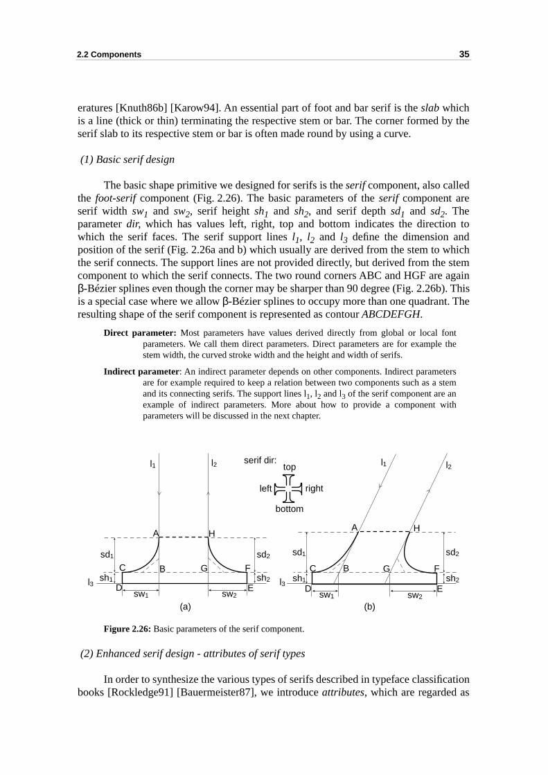
2.2 Components 35
y the
n to
hich stem againb). ThisThe
tthe
rstem
h
cation
eratures [Knuth86b] [Karow94]. An essential part of foot and bar serif is the slab whichis a line (thick or thin) terminating the respective stem or bar. The corner formed bserif slab to its respective stem or bar is often made round by using a curve.
(1) Basic serif design
The basic shape primitive we designed for serifs is the serif component, also calledthe foot-serif component (Fig. 2.26). The basic parameters of the serif component areserif width sw1 and sw2, serif height sh1 and sh2, and serif depth sd1 and sd2. Theparameter dir, which has values left, right, top and bottom indicates the directiowhich the serif faces. The serif support lines l1, l2 and l3 define the dimension andposition of the serif (Fig. 2.26a and b) which usually are derived from the stem to wthe serif connects. The support lines are not provided directly, but derived from thecomponent to which the serif connects. The two round corners ABC and HGF areβ-Bézier splines even though the corner may be sharper than 90 degree (Fig. 2.26is a special case where we allow β-Bézier splines to occupy more than one quadrant. resulting shape of the serif component is represented as contour ABCDEFGH.
Direct parameter: Most parameters have values derived directly from global or local fonparameters. We call them direct parameters. Direct parameters are for example stem width, the curved stroke width and the height and width of serifs.
Indirect parameter: An indirect parameter depends on other components. Indirect parameteare for example required to keep a relation between two components such as a sand its connecting serifs. The support lines l1, l2 and l3 of the serif component are anexample of indirect parameters. More about how to provide a component witparameters will be discussed in the next chapter.
Figure 2.26: Basic parameters of the serif component.
(2) Enhanced serif design - attributes of serif types
In order to synthesize the various types of serifs described in typeface classifibooks [Rockledge91] [Bauermeister87], we introduce attributes, which are regarded as
A
BC
D E
FG
H
sw1 sw2
l1 l2
l3sh2sh1
sd2sd1
l1 l2
A H
l3
C
D
B G
E
F
sw1 sw2
sh2
sd2
sh1
sd1
serif dir:
left
top
right
bottom
(a) (b)
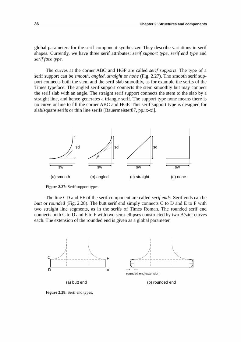
36 Chapter 2: Structures and components
n serif
- of theonnectb by athere isd for
ithif endurves
global parameters for the serif component synthesizer. They describe variations ishapes. Currently, we have three serif attributes: serif support type, serif end type andserif face type.
The curves at the corner ABC and HGF are called serif supports. The type of aserif support can be smooth, angled, straight or none (Fig. 2.27). The smooth serif support connects both the stem and the serif slab smoothly, as for example the serifsTimes typeface. The angled serif support connects the stem smoothly but may cthe serif slab with an angle. The straight serif support connects the stem to the slastraight line, and hence generates a triangle serif. The support type none means no curve or line to fill the corner ABC and HGF. This serif support type is designeslab/square serifs or thin line serifs [Bauermeister87, pp.ix-xi].
Figure 2.27: Serif support types.
The line CD and EF of the serif component are called serif ends. Serif ends can bebutt or rounded (Fig. 2.28). The butt serif end simply connects C to D and E to F wtwo straight line segments, as in the serifs of Times Roman. The rounded serconnects both C to D and E to F with two semi-ellipses constructed by two Bézier ceach. The extension of the rounded end is given as a global parameter.
Figure 2.28: Serif end types.
sd
sw
θ
sd
sw
sd
sw sw
(a) smooth (b) angled (c) straight (d) none
rounded end extension
(a) butt end (b) rounded end
C
D E
F
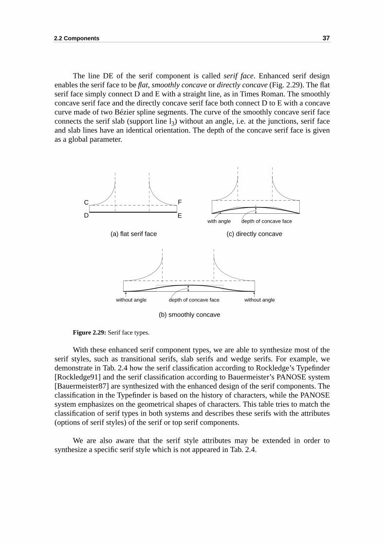
2.2 Components 37
othlyncave
rif facece given
t of thele, wefinderystemts. TheOSE
atch theributes
er to
The line DE of the serif component is called serif face. Enhanced serif designenables the serif face to be flat, smoothly concave or directly concave (Fig. 2.29). The flatserif face simply connect D and E with a straight line, as in Times Roman. The smoconcave serif face and the directly concave serif face both connect D to E with a cocurve made of two Bézier spline segments. The curve of the smoothly concave seconnects the serif slab (support line l3) without an angle, i.e. at the junctions, serif faand slab lines have an identical orientation. The depth of the concave serif face isas a global parameter.
Figure 2.29: Serif face types.
With these enhanced serif component types, we are able to synthesize mosserif styles, such as transitional serifs, slab serifs and wedge serifs. For exampdemonstrate in Tab. 2.4 how the serif classification according to Rockledge’s Type[Rockledge91] and the serif classification according to Bauermeister’s PANOSE s[Bauermeister87] are synthesized with the enhanced design of the serif componenclassification in the Typefinder is based on the history of characters, while the PANsystem emphasizes on the geometrical shapes of characters. This table tries to mclassification of serif types in both systems and describes these serifs with the att(options of serif styles) of the serif or top serif components.
We are also aware that the serif style attributes may be extended in ordsynthesize a specific serif style which is not appeared in Tab. 2.4.
depth of concave face
depth of concave facewith angle
without angle without angle
(c) directly concave(a) flat serif face
(b) smoothly concave
C
D E
F
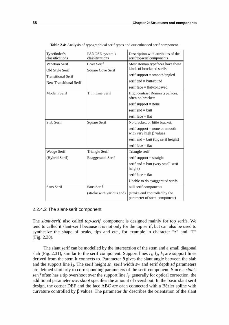
38 Chapter 2: Structures and components
esed tod “T”
gonal
ab
erife withnt
Table 2.4: Analysis of typographical serif types and our enhanced serif component.
2.2.4.2 The slant-serif component
The slant-serif, also called top-serif, component is designed mainly for top serifs. Wtend to called it slant-serif because it is not only for the top serif, but can also be usynthesize the shape of beaks, tips and etc., for example in character “z” an(Fig. 2.30).
The slant serif can be modelled by the intersection of the stem and a small diaslab (Fig. 2.31), similar to the serif component. Support lines l1, l2, l3 are support linesderived from the stem it connects to. Parameter θ gives the slant angle between the sland the support line l3. The serif height sh, serif width sw and serif depth sd parametersare defined similarly to corresponding parameters of the serif component. Since aslant-serif often has a tip overshoot over the support line l3, generally for optical correction, theadditional parameter overshoot specifies the amount of overshoot. In the basic slant sdesign, the corner DEF and the face ABC are each connected with a Bézier splincurvature controlled by β values. The parameter dir describes the orientation of the sla
Typefinder’sclassifications
PANOSE system’sclassifications
Description with attributes of the serif/topserif components
Venetian Serif
Old Style Serif
Transitional Serif
New Transitional Serif
Cove Serif
Square Cove Serif
Most Roman typefaces have these kinds of bracketed serifs:
serif support = smooth/angled
serif end = butt/round
serif face = flat/concaved.
Modern Serif Thin Line Serif High contrast Roman typefaces, often no bracket:
serif support = none
serif end = butt
serif face = flat
Slab Serif Square Serif No bracket, or little bracket:
serif support = none or smooth with very high β values
serif end = butt (big serif height)
serif face = flat
Wedge Serif
(Hybrid Serif)
Triangle Serif
Exaggerated Serif
Triangle serif:
serif support = straight
serif end = butt (very small serif height)
serif face = flat
Unable to do exaggerated serifs.
Sans Serif Sans Serif
(stroke with various end)
null serif components
(stroke end controlled by the parameter of stem component)
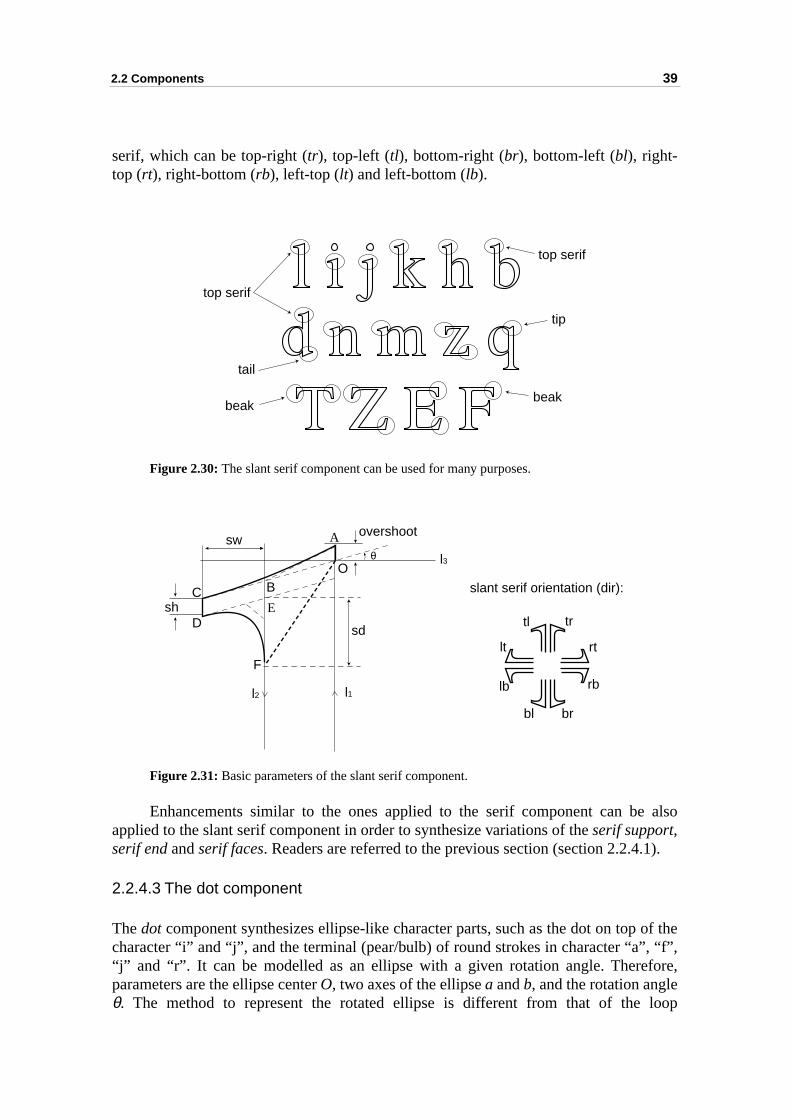
2.2 Components 39
also
1).
of the “f”,ore,
loop
serif, which can be top-right (tr), top-left (tl), bottom-right (br), bottom-left (bl), right-top (rt), right-bottom (rb), left-top (lt) and left-bottom (lb).
Figure 2.30: The slant serif component can be used for many purposes.
Figure 2.31: Basic parameters of the slant serif component.
Enhancements similar to the ones applied to the serif component can beapplied to the slant serif component in order to synthesize variations of the serif support,serif end and serif faces. Readers are referred to the previous section (section 2.2.4.
2.2.4.3 The dot component
The dot component synthesizes ellipse-like character parts, such as the dot on topcharacter “i” and “j”, and the terminal (pear/bulb) of round strokes in character “a”,“j” and “r”. It can be modelled as an ellipse with a given rotation angle. Therefparameters are the ellipse center O, two axes of the ellipse a and b, and the rotation angleθ. The method to represent the rotated ellipse is different from that of the
top serif
beakbeak
tip
top serif
tail
A
BC
l1l2
l3
D
F
O
E
θ
overshootsw
sh
sdtrtl
rt
rb
brbl
lb
lt
slant serif orientation (dir):
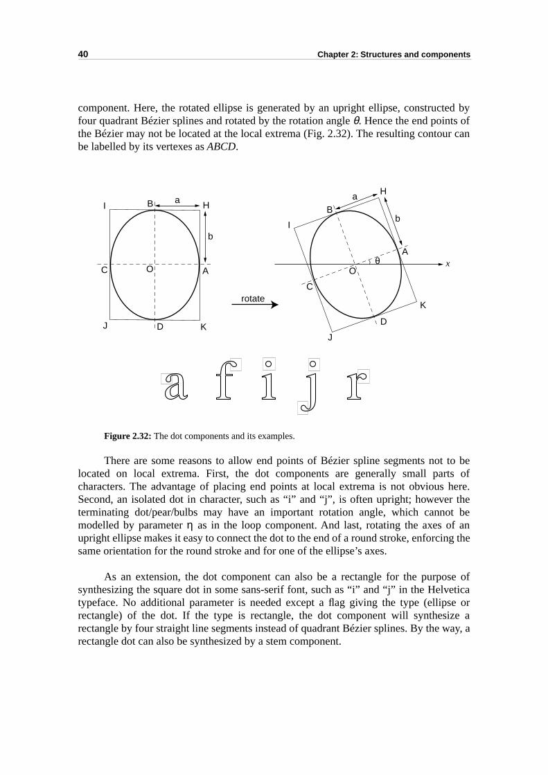
40 Chapter 2: Structures and components
ted byfur can
to berts of here.r theot be aning the
ose ofeticase orize away, a
component. Here, the rotated ellipse is generated by an upright ellipse, construcfour quadrant Bézier splines and rotated by the rotation angle θ. Hence the end points othe Bézier may not be located at the local extrema (Fig. 2.32). The resulting contobe labelled by its vertexes as ABCD.
Figure 2.32: The dot components and its examples.
There are some reasons to allow end points of Bézier spline segments notlocated on local extrema. First, the dot components are generally small pacharacters. The advantage of placing end points at local extrema is not obviousSecond, an isolated dot in character, such as “i” and “j”, is often upright; howeveterminating dot/pear/bulbs may have an important rotation angle, which cannmodelled by parameter η as in the loop component. And last, rotating the axes ofupright ellipse makes it easy to connect the dot to the end of a round stroke, enforcsame orientation for the round stroke and for one of the ellipse’s axes.
As an extension, the dot component can also be a rectangle for the purpsynthesizing the square dot in some sans-serif font, such as “i” and “j” in the Helvtypeface. No additional parameter is needed except a flag giving the type (elliprectangle) of the dot. If the type is rectangle, the dot component will synthesrectangle by four straight line segments instead of quadrant Bézier splines. By the rectangle dot can also be synthesized by a stem component.
b
a
A
B
C
D
O
HI
J K
θA
b
aB
C
D
Ox
H
I
J
Krotate
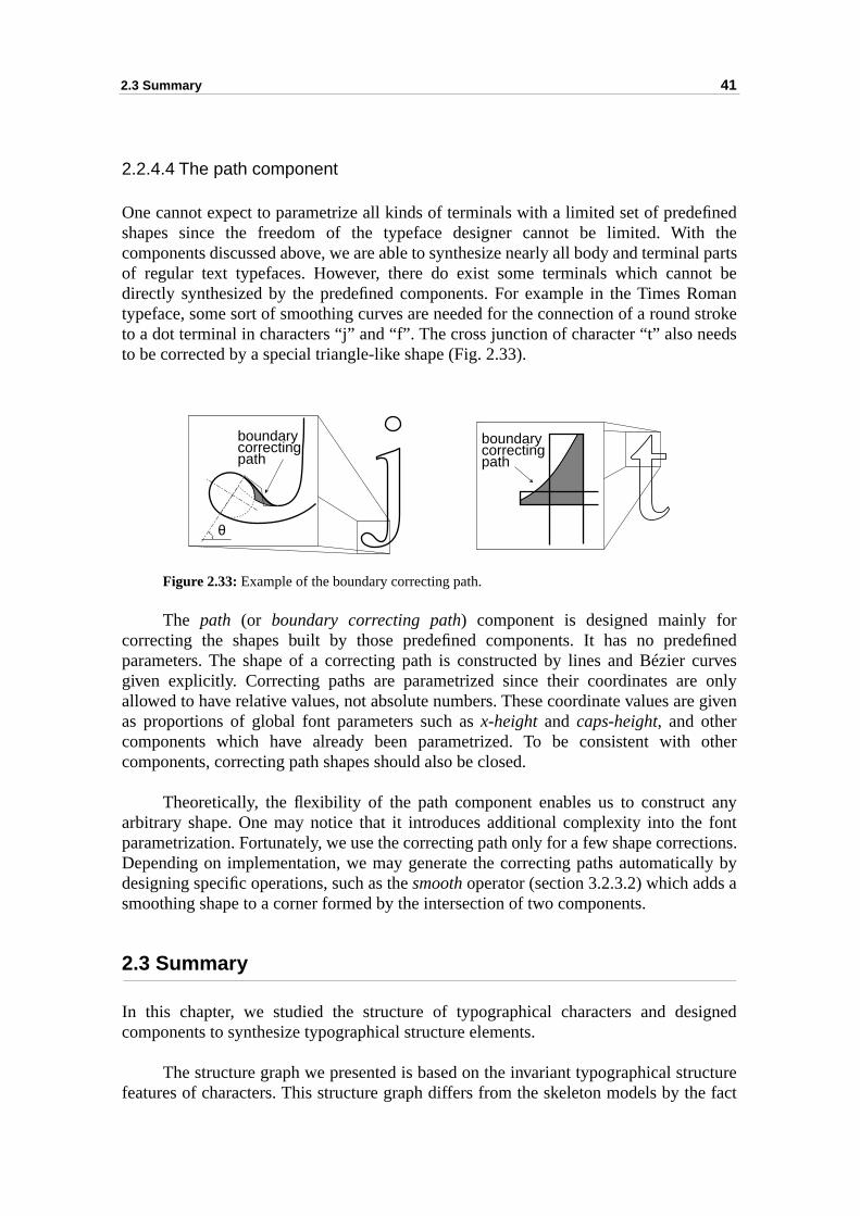
2.3 Summary 41
finedh theal partsot beoman stroke
eeds
refinedcurves onlye given
other
any fontctions.lly by a
igned
ucturee fact
2.2.4.4 The path component
One cannot expect to parametrize all kinds of terminals with a limited set of predeshapes since the freedom of the typeface designer cannot be limited. Witcomponents discussed above, we are able to synthesize nearly all body and terminof regular text typefaces. However, there do exist some terminals which canndirectly synthesized by the predefined components. For example in the Times Rtypeface, some sort of smoothing curves are needed for the connection of a roundto a dot terminal in characters “j” and “f”. The cross junction of character “t” also nto be corrected by a special triangle-like shape (Fig. 2.33).
Figure 2.33: Example of the boundary correcting path.
The path (or boundary correcting path) component is designed mainly focorrecting the shapes built by those predefined components. It has no predparameters. The shape of a correcting path is constructed by lines and Bézier given explicitly. Correcting paths are parametrized since their coordinates areallowed to have relative values, not absolute numbers. These coordinate values aras proportions of global font parameters such as x-height and caps-height, and othercomponents which have already been parametrized. To be consistent with components, correcting path shapes should also be closed.
Theoretically, the flexibility of the path component enables us to constructarbitrary shape. One may notice that it introduces additional complexity into theparametrization. Fortunately, we use the correcting path only for a few shape correDepending on implementation, we may generate the correcting paths automaticadesigning specific operations, such as the smooth operator (section 3.2.3.2) which addssmoothing shape to a corner formed by the intersection of two components.
2.3 Summary
In this chapter, we studied the structure of typographical characters and descomponents to synthesize typographical structure elements.
The structure graph we presented is based on the invariant typographical strfeatures of characters. This structure graph differs from the skeleton models by th
θ
boundarycorrectingpath
boundarycorrectingpath
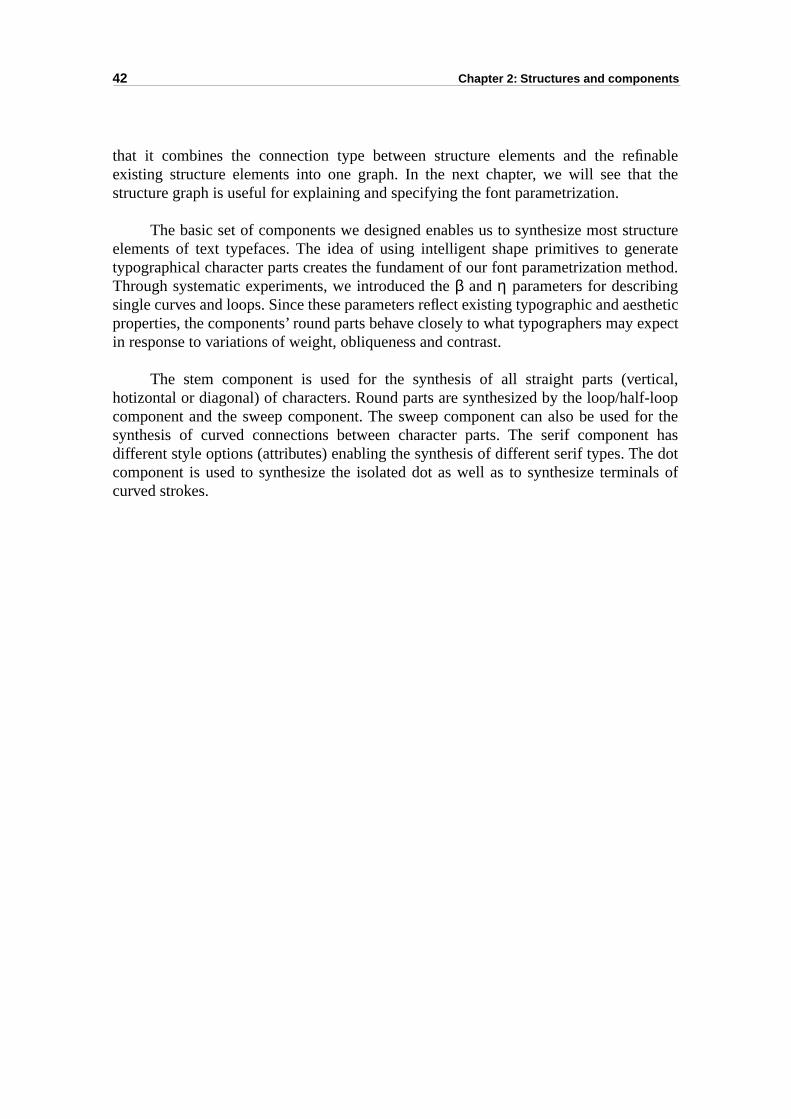
42 Chapter 2: Structures and components
finableat the
ructureerateethod.
esthetic expect
tical,lf-loop for thent hase dotnals of
that it combines the connection type between structure elements and the reexisting structure elements into one graph. In the next chapter, we will see thstructure graph is useful for explaining and specifying the font parametrization.
The basic set of components we designed enables us to synthesize most stelements of text typefaces. The idea of using intelligent shape primitives to gentypographical character parts creates the fundament of our font parametrization mThrough systematic experiments, we introduced the β and η parameters for describingsingle curves and loops. Since these parameters reflect existing typographic and aproperties, the components’ round parts behave closely to what typographers mayin response to variations of weight, obliqueness and contrast.
The stem component is used for the synthesis of all straight parts (verhotizontal or diagonal) of characters. Round parts are synthesized by the loop/hacomponent and the sweep component. The sweep component can also be usedsynthesis of curved connections between character parts. The serif componedifferent style options (attributes) enabling the synthesis of different serif types. Thcomponent is used to synthesize the isolated dot as well as to synthesize termicurved strokes.
43
ph andizable
ain
dentponent
gives aich canntations
s andd into
racterg order
thesisll the
differ,y justerent of thearacter which
CHAPTER 3
Font parametrization
In the previous chapter, we have discussed the structure element connecting grathe basic character components. In this chapter, we will present how parametrcharacters and fonts are synthesized.
First of all, the framework of our font parametrization system consists of two mparts: the parametrizable character synthesizer and the parameter files, as shown inFig. 3.1. The parametrizable character synthesizer consists of font-independent parame-trizable character synthesis methods (one for each character) and a library of compo-nents and operations that is used by the synthesis methods. The font-indepenparametrizable character synthesis methods define for each character the comshapes and their connection types. The refined structure graph of each charactervisual representation of component shapes and connection types. Parameters (whbe regarded as function arguments) are used to control shapes, positions and orieof components. Hence they are font specific. The parameter files contain concreteparameter values for each parametrizable font, including those for global font stylethose for individual character features. Parameter files have been organizehierarchical layers. The parametrizable character synthesis methods contain parameterentries to be filled by parameters from the parameter files. The parametrizable chasynthesizer has a component and operation library containing procedures for creatincomponent shapes, and geometric algorithms for realizing assembly operations into assemble components into a full character.
In order to completely specify font-independent parametrizable character synmethods, we first need to refine the structure element connecting graph for atypefaces which we would like to synthesize. Typefaces whose structure does notbut whose height proportion, weight and contrast differ can be synthesized bmodifying parameters. However, typefaces whose structure differ require diffparametrizable character synthesis methods. Let us first present the refinementstructure element connecting graph before we present the parametrizable chsynthesis methods. The parameter file organization is another important aspectwill be also discussed in detail in this chapter.
44 Chapter 3: Font parametrization
of thetructuretructure shape.
ng allver alls. Theresent thert. Wet also tons oftyles.
thatr87]..4 are
Figure 3.1: Framework of our parametrizable font synthesis system.
3.1 Earmark-based refinement of structure graphs
A structure element connecting graph is a typeface-independent representation spatial relationship between structure elements of a character. To synthesize the selements, we have designed several shape primitives called components. Each selement can be synthesized by one or more components depending on its concrete
However, there are so many kinds of physical character embellishments amothe typefaces that one refined structure graph for each character can hardly cotypefaces. We would like to resynthesize most of the commonly used text typefacequestion is how many variations of the refined structure graph will be needed to repa letter in all target typefaces. The answer resides in both the flexibility ofcomponents we are designing and the number of styles that we would like to suppouse components not only to synthesize the shapes of concrete character parts, bumodify the styles of the junctions between structure elements. To create variatiorefined structure element connection graph, we will analyse traditional typeface sBased on this analysis, we deduce the required variations.
3.1.1 Serif styles
The most important feature of a typeface is the serif style. It is the first ruletypographers apply to classify or identify typefaces [Rockledge91], [BauermeisteThe enhanced serif and slant-serif terminal components introduced in section 2.2
parametrisable charactersynthesis methods
library of components &
operations
parameterfiles
synthesized characterspa
ram
etris
able
cha
ract
ersy
nthe
size
r
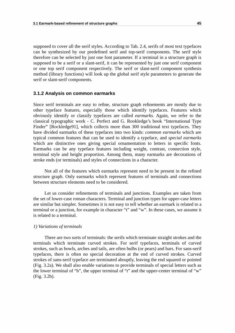
3.1 Earmark-based refinement of structure graphs 45
facesf styleraph isponentthesise the
due towhich
Typehey
onts. style,ns of
efinedctions
from lettersd to ame it
nd therved
ans-serifurved
pointeduch as“w”
supposed to cover all the serif styles. According to Tab. 2.4, serifs of most text typecan be synthesized by our predefined serif and top-serif components. The seritherefore can be selected by just one font parameter. If a terminal in a structure gsupposed to be a serif or a slant-serif, it can be represented by just one serif comor one top serif component respectively. The serif or slant-serif component synmethod (library functions) will look up the global serif style parameters to generatserif or slant-serif components.
3.1.2 Analysis on common earmarks
Since serif terminals are easy to refine, structure graph refinements are mostly other typeface features, especially those which identify typefaces. Features obviously identify or classify typefaces are called earmarks. Again, we refer to theclassical typographic work - C. Perfect and G. Rookledge’s book “International Finder” [Rockledge91], which collects more than 300 traditional text typefaces. Thave divided earmarks of these typefaces into two kinds: common earmarks which aretypical common features that can be used to identify a typeface, and special earmarkswhich are distinctive ones giving special ornamentation to letters in specific fEarmarks can be any typeface features including weight, contrast, connectionterminal style and height proportion. Among them, many earmarks are decoratiostroke ends (or terminals) and styles of connections in a character.
Not all of the features which earmarks represent need to be present in the rstructure graph. Only earmarks which represent features of terminals and connebetween structure elements need to be considered.
Let us consider refinements of terminals and junctions. Examples are takenthe set of lower-case roman characters. Terminal and junction types for upper-caseare similar but simpler. Sometimes it is not easy to tell whether an earmark is relateterminal or a junction, for example in character “t” and “w”. In these cases, we assuis related to a terminal.
1) Variations of terminals
There are two sorts of terminals: the serifs which terminate straight strokes aterminals which terminate curved strokes. For serif typefaces, terminals of custrokes, such as bowls, arches and tails, are often bulbs (or pears) and bars. For stypefaces, there is often no special decoration at the end of curved strokes. Cstrokes of sans-serif typeface are terminated abruptly, leaving the end squared or (Fig. 3.2a). We shall also enable variations to provide terminals of special letters sthe lower terminal of “b”, the upper terminal of “t” and the upper-center terminal of (Fig. 3.2b).
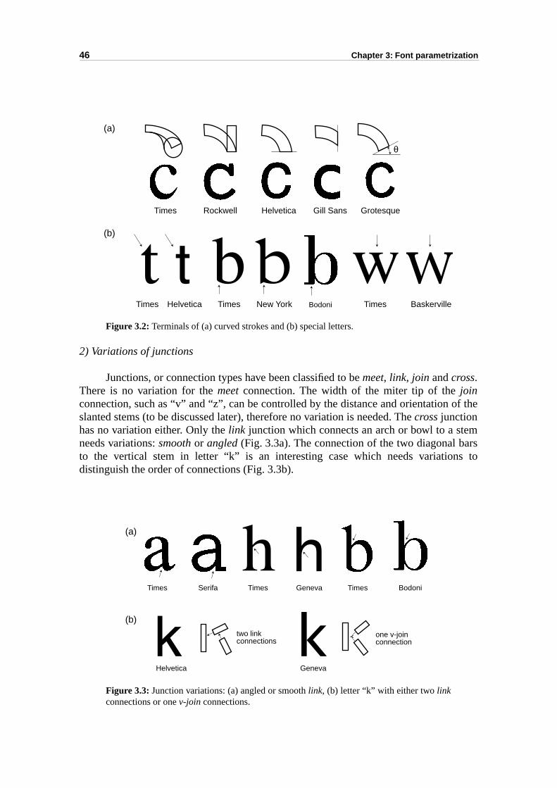
46 Chapter 3: Font parametrization
of the
mrss to
Figure 3.2: Terminals of (a) curved strokes and (b) special letters.
2) Variations of junctions
Junctions, or connection types have been classified to be meet, link, join and cross.There is no variation for the meet connection. The width of the miter tip of the joinconnection, such as “v” and “z”, can be controlled by the distance and orientation slanted stems (to be discussed later), therefore no variation is needed. The cross junctionhas no variation either. Only the link junction which connects an arch or bowl to a steneeds variations: smooth or angled (Fig. 3.3a). The connection of the two diagonal bato the vertical stem in letter “k” is an interesting case which needs variationdistinguish the order of connections (Fig. 3.3b).
Figure 3.3: Junction variations: (a) angled or smooth link, (b) letter “k” with either two linkconnections or one v-join connections.
(a)
(b)
θ
Times Rockwell Helvetica Gill Sans Grotesque
Times Helvetica Times New York Times BaskervilleBodoni
Times Serifa Times Geneva
GenevaHelvetica
Times Bodoni
v
(a)
(b)two linkconnections
one v-joinconnection
3.2 parametrizable character synthesis methods 47
havey “c-l struc-
cation.s
ent its of theust be
angleon of a Themmedes or
erticalontalizableent at as first
en twosuch asre that,aracter
font
”
3) Variation of global character structure
Besides the local variations of terminals and junctions, some charactersdifferent global structures, such as the double storey “a” vs. the single storea”(Fig. 2.8) and the “g” with a belly vs. the “g” with a tail. If the shape of a specific charater can not be obtained by appropriate combinations of components, a new globature can be introduced.
3.2 parametrizable character synthesis methods
The refined structure element connecting graph is an abstract character part specifiThis specification is used to write the code of the parametrizable character synthesimethod of a given character.
The parametrizable character synthesis method requires for each componcorresponding parameters. The parameters of a component specify the positioncomponent and its precise shape. Certain relationships between components mmaintained. The shape of a component is controlled by the dimension, orientation,and curvature parameters. The shape of a component (for example the extensistem) may also need to be trimmed in order to fit well with other components.synthesized character shapes, or glyphs, will be represented in the form of tricomponent outlines, which in turn can be intersected and merged into glyph outlinscan-converted into glyph bitmaps.
3.2.1 Component position dependency
The first step is the placement of each component at a proper position. The vposition is controlled by the traditional reference lines. In respect to the horizposition, the origin and the left side bearing point are not specified in the parametrcharacter synthesis method. We can generally place the first synthesized componrandom horizontal position. Positions of the other components are relative to thicomponent.
3.2.1.1 Relationships between components
There are two kinds of component-to-component relationships: the distance betwecomponents, such as two vertical stems, and the connection of two components, a serif and its connecting stem. Some relationships must be maintained to ensuproviding any proper parameters, the font synthesizer can generate reasonable chglyphs.
Relationships between character parts were used in the traditional outlinetechnology to specify hinting methods, such as “the line connecting pi and pj is vertical”,“the distance between the horizontal projections of pi and pj is the standard stem width
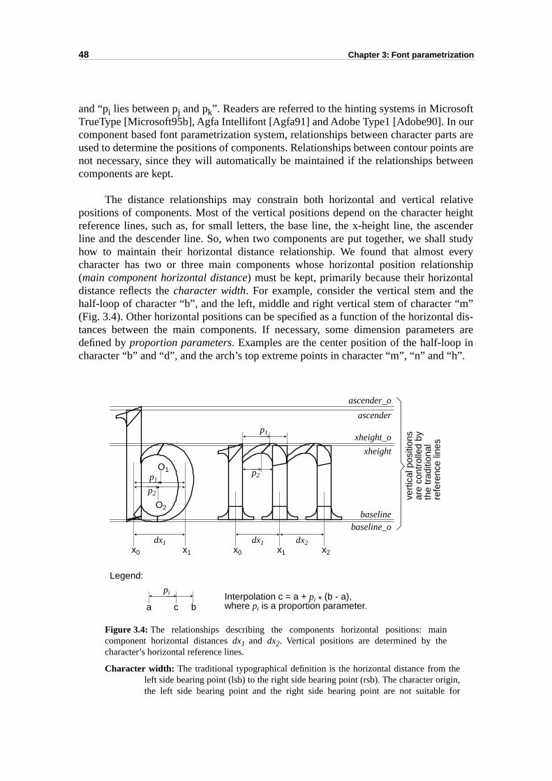
48 Chapter 3: Font parametrization
oftur
arts areints areween
ativeheightcenderll studyverynship
talthe“m”l dis-ers are in”.
,r
and “pi lies between pj and pk”. Readers are referred to the hinting systems in MicrosTrueType [Microsoft95b], Agfa Intellifont [Agfa91] and Adobe Type1 [Adobe90]. In ocomponent based font parametrization system, relationships between character pused to determine the positions of components. Relationships between contour ponot necessary, since they will automatically be maintained if the relationships betcomponents are kept.
The distance relationships may constrain both horizontal and vertical relpositions of components. Most of the vertical positions depend on the character reference lines, such as, for small letters, the base line, the x-height line, the asline and the descender line. So, when two components are put together, we shahow to maintain their horizontal distance relationship. We found that almost echaracter has two or three main components whose horizontal position relatio(main component horizontal distance) must be kept, primarily because their horizondistance reflects the character width. For example, consider the vertical stem and half-loop of character “b”, and the left, middle and right vertical stem of character (Fig. 3.4). Other horizontal positions can be specified as a function of the horizontatances between the main components. If necessary, some dimension parametdefined by proportion parameters. Examples are the center position of the half-loopcharacter “b” and “d”, and the arch’s top extreme points in character “m”, “n” and “h
Figure 3.4: The relationships describing the components horizontal positions: maincomponent horizontal distances dx1 and dx2. Vertical positions are determined by thecharacter’s horizontal reference lines.
Character width: The traditional typographical definition is the horizontal distance from theleft side bearing point (lsb) to the right side bearing point (rsb). The character originthe left side bearing point and the right side bearing point are not suitable fo
ascender_o
ascender
xheight_o
xheight
baselinebaseline_o
dx1 dx1 dx2x0 x1 x0 x1 x2
O1
O2
p1
p2
p1
p2
vert
ical
pos
ition
sar
e co
ntro
lled
byth
e tr
aditi
onal
refe
renc
e lin
es
pi
a c b
Legend:
Interpolation c = a + pi * (b - a),where pi is a proportion parameter.
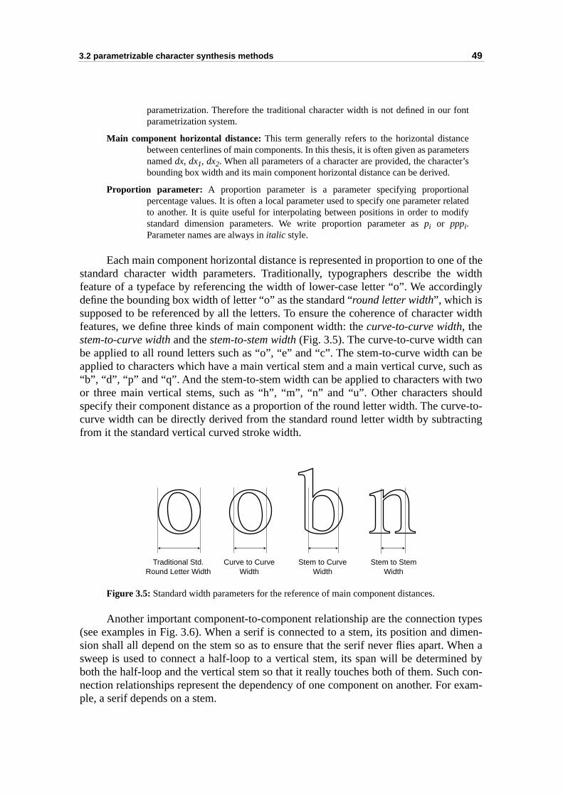
3.2 parametrizable character synthesis methods 49
t
ers’s
ted
of thewidthingly
r width
nn beuch astwoouldve-to-cting
typesdimen-When aed by con-
r exam-
parametrization. Therefore the traditional character width is not defined in our fonparametrization system.
Main component horizontal distance: This term generally refers to the horizontal distancebetween centerlines of main components. In this thesis, it is often given as parametnamed dx, dx1, dx2. When all parameters of a character are provided, the characterbounding box width and its main component horizontal distance can be derived.
Proportion parameter: A proportion parameter is a parameter specifying proportionalpercentage values. It is often a local parameter used to specify one parameter relato another. It is quite useful for interpolating between positions in order to modifystandard dimension parameters. We write proportion parameter as pi or pppi.Parameter names are always in italic style.
Each main component horizontal distance is represented in proportion to onestandard character width parameters. Traditionally, typographers describe the feature of a typeface by referencing the width of lower-case letter “o”. We accorddefine the bounding box width of letter “o” as the standard “round letter width”, which issupposed to be referenced by all the letters. To ensure the coherence of charactefeatures, we define three kinds of main component width: the curve-to-curve width, thestem-to-curve width and the stem-to-stem width (Fig. 3.5). The curve-to-curve width cabe applied to all round letters such as “o”, “e” and “c”. The stem-to-curve width caapplied to characters which have a main vertical stem and a main vertical curve, s“b”, “d”, “p” and “q”. And the stem-to-stem width can be applied to characters with or three main vertical stems, such as “h”, “m”, “n” and “u”. Other characters shspecify their component distance as a proportion of the round letter width. The curcurve width can be directly derived from the standard round letter width by subtrafrom it the standard vertical curved stroke width.
Figure 3.5: Standard width parameters for the reference of main component distances.
Another important component-to-component relationship are the connection (see examples in Fig. 3.6). When a serif is connected to a stem, its position and sion shall all depend on the stem so as to ensure that the serif never flies apart. sweep is used to connect a half-loop to a vertical stem, its span will be determinboth the half-loop and the vertical stem so that it really touches both of them. Suchnection relationships represent the dependency of one component on another. Fople, a serif depends on a stem.
Traditional Std. Round Letter Width
Curve to CurveWidth
Stem to CurveWidth
Stem to StemWidth
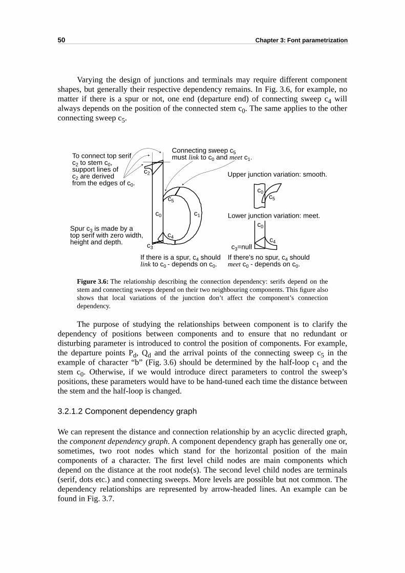
50 Chapter 3: Font parametrization
nentple, no
r
theant ormple,
ep’setween
graph, or,
mainwhichrminalsn. Thecan be
Varying the design of junctions and terminals may require different composhapes, but generally their respective dependency remains. In Fig. 3.6, for exammatter if there is a spur or not, one end (departure end) of connecting sweep c4 willalways depends on the position of the connected stem c0. The same applies to the otheconnecting sweep c5.
Figure 3.6: The relationship describing the connection dependency: serifs depend on thestem and connecting sweeps depend on their two neighbouring components. This figure alsoshows that local variations of the junction don’t affect the component’s connectiondependency.
The purpose of studying the relationships between component is to clarifydependency of positions between components and to ensure that no redunddisturbing parameter is introduced to control the position of components. For exathe departure points Pd, Qd and the arrival points of the connecting sweep c5 in theexample of character “b” (Fig. 3.6) should be determined by the half-loop c1 and thestem c0. Otherwise, if we would introduce direct parameters to control the swepositions, these parameters would have to be hand-tuned each time the distance bthe stem and the half-loop is changed.
3.2.1.2 Component dependency graph
We can represent the distance and connection relationship by an acyclic directedthe component dependency graph. A component dependency graph has generally onesometimes, two root nodes which stand for the horizontal position of the components of a character. The first level child nodes are main components depend on the distance at the root node(s). The second level child nodes are te(serif, dots etc.) and connecting sweeps. More levels are possible but not commodependency relationships are represented by arrow-headed lines. An example found in Fig. 3.7.
c0 c1
c5c5
c4
c2
c3
c0
c0
c4c3=null
Connecting sweep c5must link to c0 and meet c1.To connect top serif
c2 to stem c0,support lines ofc2 are derivedfrom the edges of c0.
Spur c3 is made by atop serif with zero width,height and depth.
If there is a spur, c4 shouldlink to c0 - depends on c0.
If there's no spur, c4 shouldmeet c0 - depends on c0.
Lower junction variation: meet.
Upper junction variation: smooth.
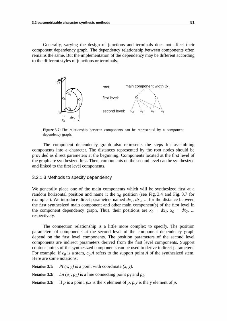
3.2 parametrizable character synthesis methods 51
theirts oftenording
mblingould beevel ofthesized
t at ar
nvel in
ition graph level
upportmeters..
Generally, varying the design of junctions and terminals does not affect component dependency graph. The dependency relationship between componenremains the same. But the implementation of the dependency may be different accto the different styles of junctions or terminals.
Figure 3.7: The relationship between components can be represented by a componentdependency graph.
The component dependency graph also represents the steps for assecomponents into a character. The distances represented by the root nodes shprovided as direct parameters at the beginning. Components located at the first lthe graph are synthesized first. Then, components on the second level can be synand linked to the first level components.
3.2.1.3 Methods to specify dependency
We generally place one of the main components which will be synthesized firsrandom horizontal position and name it the x0 position (see Fig. 3.4 and Fig. 3.7 foexamples). We introduce direct parameters named dx1, dx2, ... for the distance betweethe first synthesized main component and other main component(s) of the first lethe component dependency graph. Thus, their positions are x0 + dx1, x0 + dx2, ...respectively.
The connection relationship is a little more complex to specify. The posparameters of components at the second level of the component dependencydepend on the first level components. The position parameters of the secondcomponents are indirect parameters derived from the first level components. Scontour points of the synthesized components can be used to derive indirect paraFor example, if c0 is a stem, c0.A refers to the support point A of the synthesized stemHere are some notations:
Notation 3.1: Pt (x, y) is a point with coordinate (x, y).
Notation 3.2: Ln (p1, p2) is a line connecting point p1 and p2.
Notation 3.3: If p is a point, p.x is the x element of p, p.y is the y element of p.
c0c0c1
c1
c5
c5c4 c4c2
c2
c3c3
main component width dx1
dx1
root:
first level:
second level:
x0 x1
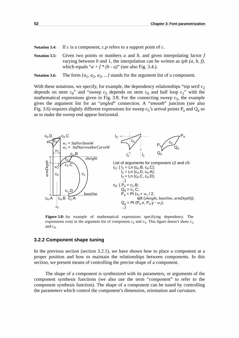
52 Chapter 3: Font parametrization
erif c
nt at a this
of theo therollinge.
Notation 3.4: If c is a component, c.p refers to a support point of c.
Notation 3.5: Given two points or numbers a and b, and given interpolating factor fvarying between 0 and 1, the interpolation can be written as iplt (a, b, f),which equals “a + f * (b - a)” (see also Fig. 3.4.).
Notation 3.6: The form {a1, a2, a3, ...} stands for the argument list of a component.
With these notations, we specify, for example, the dependency relationships “top s2depends on stem c0” and “sweep c5 depends on stem c0 and half loop c1” with themathematical expressions given in Fig. 3.8. For the connecting sweep c5, the examplegives the argument list for an “angled” connection. A “smooth” junction (see alsoFig. 3.6) requires slightly different expressions for sweep c5’s arrival points Pa and Qa soas to make the sweep end appear horizontal.
Figure 3.8: An example of mathematical expressions specifying dependency. Theexpressions exist in the argument list of component c2 and c5. This figure doesn’t show c3and c4.
3.2.2 Component shape tuning
In the previous section (section 3.2.1), we have shown how to place a componeproper position and how to maintain the relationships between components. Insection, we present means of controlling the precise shape of a component.
The shape of a component is synthesized with its parameters, or argumentscomponent synthesis functions (we also use the term “component” to refer tcomponent synthesis function). The shape of a component can be tuned by contthe parameters which control the component’s dimension, orientation and curvatur
c0 c1
c5
c5c2 c2
x0
List of arguments for component c2 and c5:c2: { l1 = Ln (c0.B, c0.C);
l2 = Ln (c0.D, c0.A);l3 = Ln (c0.C, c0.D);...}
c5: { Pd = c1.B;Qd = c1.C;Pa = Pt (x0 + w1 / 2,
iplt (xheight, baseline, armDepth));Qa = Pt (Pa.x, Pa.y - w2);...}
c0.Cc0.D
c1.A
c1.D
c1.B
c1.C
c0.A c0.B
xheight
baseline
arm
Dep
th
w1
w2
w1 = StdVerStemWw2 = StdNarrowHorCurveW
Pd
QdPa
Qa
l3
l2 l1
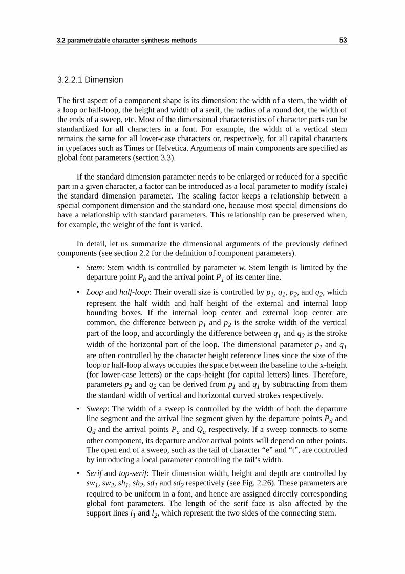
3.2 parametrizable character synthesis methods 53
idth ofth of can bestemractersified as
pecific (scale)
een asions do when,
fined
loop arel
of theheightfore,
ture
eoints.rolled
by arending the
.
3.2.2.1 Dimension
The first aspect of a component shape is its dimension: the width of a stem, the wa loop or half-loop, the height and width of a serif, the radius of a round dot, the widthe ends of a sweep, etc. Most of the dimensional characteristics of character partsstandardized for all characters in a font. For example, the width of a vertical remains the same for all lower-case characters or, respectively, for all capital chain typefaces such as Times or Helvetica. Arguments of main components are specglobal font parameters (section 3.3).
If the standard dimension parameter needs to be enlarged or reduced for a spart in a given character, a factor can be introduced as a local parameter to modifythe standard dimension parameter. The scaling factor keeps a relationship betwspecial component dimension and the standard one, because most special dimenhave a relationship with standard parameters. This relationship can be preservedfor example, the weight of the font is varied.
In detail, let us summarize the dimensional arguments of the previously decomponents (see section 2.2 for the definition of component parameters).
• Stem: Stem width is controlled by parameter w. Stem length is limited by thedeparture point P0 and the arrival point P1 of its center line.
• Loop and half-loop: Their overall size is controlled by p1, q1, p2, and q2, whichrepresent the half width and half height of the external and internal bounding boxes. If the internal loop center and external loop centercommon, the difference between p1 and p2 is the stroke width of the verticapart of the loop, and accordingly the difference between q1 and q2 is the strokewidth of the horizontal part of the loop. The dimensional parameter p1 and q1
are often controlled by the character height reference lines since the size loop or half-loop always occupies the space between the baseline to the x-(for lower-case letters) or the caps-height (for capital letters) lines. Thereparameters p2 and q2 can be derived from p1 and q1 by subtracting from themthe standard width of vertical and horizontal curved strokes respectively.
• Sweep: The width of a sweep is controlled by the width of both the deparline segment and the arrival line segment given by the departure points Pd andQd and the arrival points Pa and Qa respectively. If a sweep connects to somother component, its departure and/or arrival points will depend on other pThe open end of a sweep, such as the tail of character “e” and “t”, are contby introducing a local parameter controlling the tail’s width.
• Serif and top-serif: Their dimension width, height and depth are controlledsw1, sw2, sh1, sh2, sd1 and sd2 respectively (see Fig. 2.26). These parametersrequired to be uniform in a font, and hence are assigned directly correspoglobal font parameters. The length of the serif face is also affected bysupport lines l1 and l2, which represent the two sides of the connecting stem
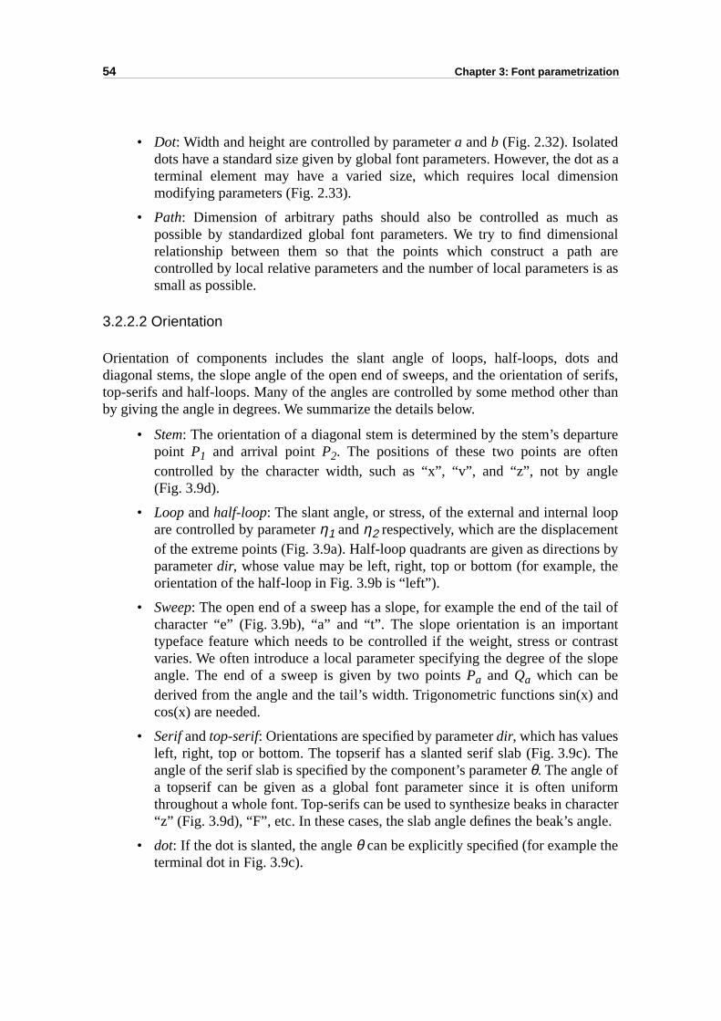
54 Chapter 3: Font parametrization
ot as asion
asional are is as
andf serifs,r than
rturen
gle
oopntns bythe
tail ofantntrastslope
and
The
formractergle.
e
• Dot: Width and height are controlled by parameter a and b (Fig. 2.32). Isolateddots have a standard size given by global font parameters. However, the dterminal element may have a varied size, which requires local dimenmodifying parameters (Fig. 2.33).
• Path: Dimension of arbitrary paths should also be controlled as muchpossible by standardized global font parameters. We try to find dimensrelationship between them so that the points which construct a pathcontrolled by local relative parameters and the number of local parameterssmall as possible.
3.2.2.2 Orientation
Orientation of components includes the slant angle of loops, half-loops, dotsdiagonal stems, the slope angle of the open end of sweeps, and the orientation otop-serifs and half-loops. Many of the angles are controlled by some method otheby giving the angle in degrees. We summarize the details below.
• Stem: The orientation of a diagonal stem is determined by the stem’s depapoint P1 and arrival point P2. The positions of these two points are oftecontrolled by the character width, such as “x”, “v”, and “z”, not by an(Fig. 3.9d).
• Loop and half-loop: The slant angle, or stress, of the external and internal lare controlled by parameter η1 and η2 respectively, which are the displacemeof the extreme points (Fig. 3.9a). Half-loop quadrants are given as directioparameter dir, whose value may be left, right, top or bottom (for example, orientation of the half-loop in Fig. 3.9b is “left”).
• Sweep: The open end of a sweep has a slope, for example the end of the character “e” (Fig. 3.9b), “a” and “t”. The slope orientation is an importtypeface feature which needs to be controlled if the weight, stress or covaries. We often introduce a local parameter specifying the degree of the angle. The end of a sweep is given by two points Pa and Qa which can bederived from the angle and the tail’s width. Trigonometric functions sin(x) cos(x) are needed.
• Serif and top-serif: Orientations are specified by parameter dir, which has valuesleft, right, top or bottom. The topserif has a slanted serif slab (Fig. 3.9c).angle of the serif slab is specified by the component’s parameter θ. The angle ofa topserif can be given as a global font parameter since it is often unithroughout a whole font. Top-serifs can be used to synthesize beaks in cha“z” (Fig. 3.9d), “F”, etc. In these cases, the slab angle defines the beak’s an
• dot: If the dot is slanted, the angle θ can be explicitly specified (for example thterminal dot in Fig. 3.9c).
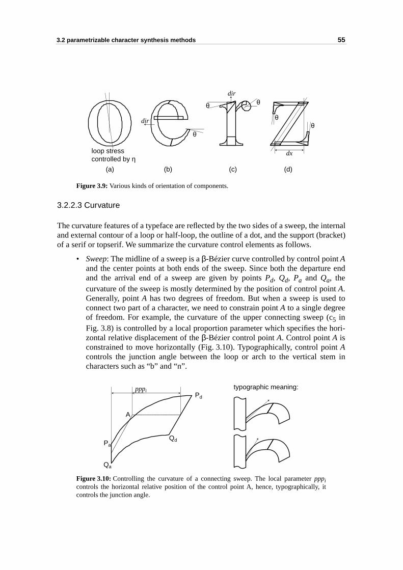
3.2 parametrizable character synthesis methods 55
internalacket)
re end
nt d to
(chori-
t m in
Figure 3.9: Various kinds of orientation of components.
3.2.2.3 Curvature
The curvature features of a typeface are reflected by the two sides of a sweep, the and external contour of a loop or half-loop, the outline of a dot, and the support (brof a serif or topserif. We summarize the curvature control elements as follows.
• Sweep: The midline of a sweep is a β-Bézier curve controlled by control point Aand the center points at both ends of the sweep. Since both the departuand the arrival end of a sweep are given by points Pd, Qd, Pa and Qa, thecurvature of the sweep is mostly determined by the position of control poiA.Generally, point A has two degrees of freedom. But when a sweep is useconnect two part of a character, we need to constrain point A to a single degreeof freedom. For example, the curvature of the upper connecting sweep 5 inFig. 3.8) is controlled by a local proportion parameter which specifies the zontal relative displacement of the β-Bézier control point A. Control point A isconstrained to move horizontally (Fig. 3.10). Typographically, control poinAcontrols the junction angle between the loop or arch to the vertical stecharacters such as “b” and “n”.
Figure 3.10: Controlling the curvature of a connecting sweep. The local parameter pppicontrols the horizontal relative position of the control point A, hence, typographically, itcontrols the junction angle.
(a) (b) (c) (d)
θθ
θ
θθ
dx
dir
dir
loop stresscontrolled by η
A
Qd
Qa
Pd
Pa
pppitypographic meaning:
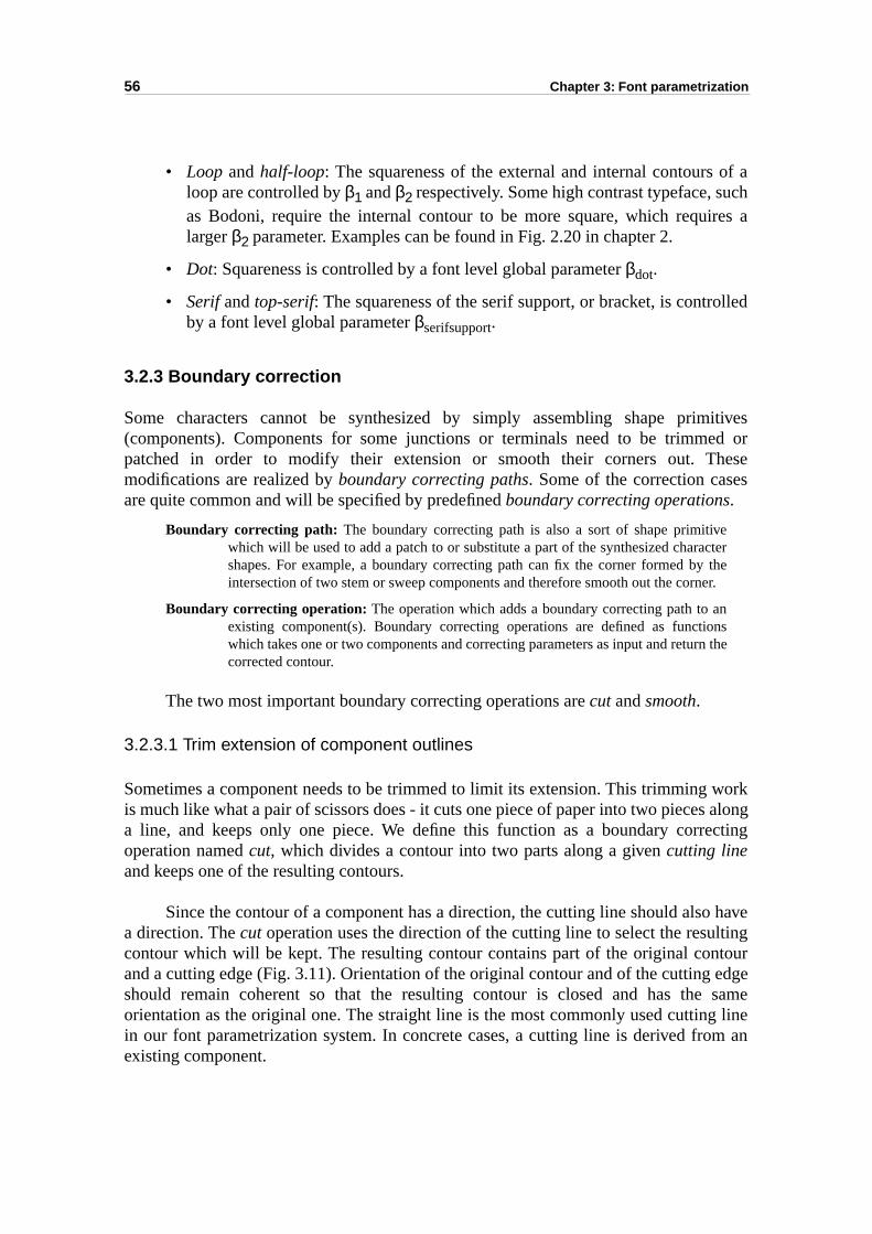
56 Chapter 3: Font parametrization
of achres a
lled
itivesed orheses
terher.
sthe
work alongecting
haveltingtour edge sameg linem an
• Loop and half-loop: The squareness of the external and internal contours loop are controlled by β1 and β2 respectively. Some high contrast typeface, suas Bodoni, require the internal contour to be more square, which requilarger β2 parameter. Examples can be found in Fig. 2.20 in chapter 2.
• Dot: Squareness is controlled by a font level global parameter βdot.
• Serif and top-serif: The squareness of the serif support, or bracket, is controby a font level global parameter βserifsupport.
3.2.3 Boundary correction
Some characters cannot be synthesized by simply assembling shape prim(components). Components for some junctions or terminals need to be trimmpatched in order to modify their extension or smooth their corners out. Tmodifications are realized by boundary correcting paths. Some of the correction caseare quite common and will be specified by predefined boundary correcting operations.
Boundary correcting path: The boundary correcting path is also a sort of shape primitivewhich will be used to add a patch to or substitute a part of the synthesized characshapes. For example, a boundary correcting path can fix the corner formed by tintersection of two stem or sweep components and therefore smooth out the corne
Boundary correcting operation: The operation which adds a boundary correcting path to anexisting component(s). Boundary correcting operations are defined as functionwhich takes one or two components and correcting parameters as input and return corrected contour.
The two most important boundary correcting operations are cut and smooth.
3.2.3.1 Trim extension of component outlines
Sometimes a component needs to be trimmed to limit its extension. This trimmingis much like what a pair of scissors does - it cuts one piece of paper into two piecesa line, and keeps only one piece. We define this function as a boundary corroperation named cut, which divides a contour into two parts along a given cutting lineand keeps one of the resulting contours.
Since the contour of a component has a direction, the cutting line should alsoa direction. The cut operation uses the direction of the cutting line to select the resucontour which will be kept. The resulting contour contains part of the original conand a cutting edge (Fig. 3.11). Orientation of the original contour and of the cuttingshould remain coherent so that the resulting contour is closed and has theorientation as the original one. The straight line is the most commonly used cuttinin our font parametrization system. In concrete cases, a cutting line is derived froexisting component.
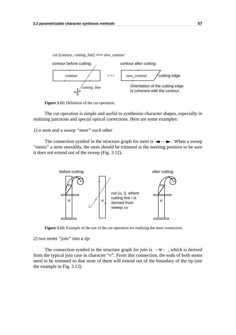
3.2 parametrizable character synthesis methods 57
ially in
e sure
tems (see
Figure 3.11: Definition of the cut operation.
The cut operation is simple and useful to synthesize character shapes, especrealizing junctions and special optical corrections. Here are some examples:
1) a stem and a sweep “meet” each other
The connection symbol in the structure graph for meet is . When a sweep“meets” a stem smoothly, the stem should be trimmed at the meeting position to bit does not extend out of the sweep (Fig. 3.12).
Figure 3.12: Example of the use of the cut operation for realizing the meet connection.
2) two stems “join” into a tip
The connection symbol in the structure graph for join is , which is derivedfrom the typical join case in character “v”. From this connection, the ends of both sneed to be trimmed so that none of them will extend out of the boundary of the tipthe example in Fig. 3.13).
contour before cutting:
cutting_line
contour after cutting:
Orientation of the cutting edgeis coherent with the contour.
cutting edge
cut (contour, cutting_line) ==> new_contour
contour new_contour==>
st stst
sw sw
l
cut (st, l), where cutting line l isderived fromsweep sw
before cutting: after cutting:
v
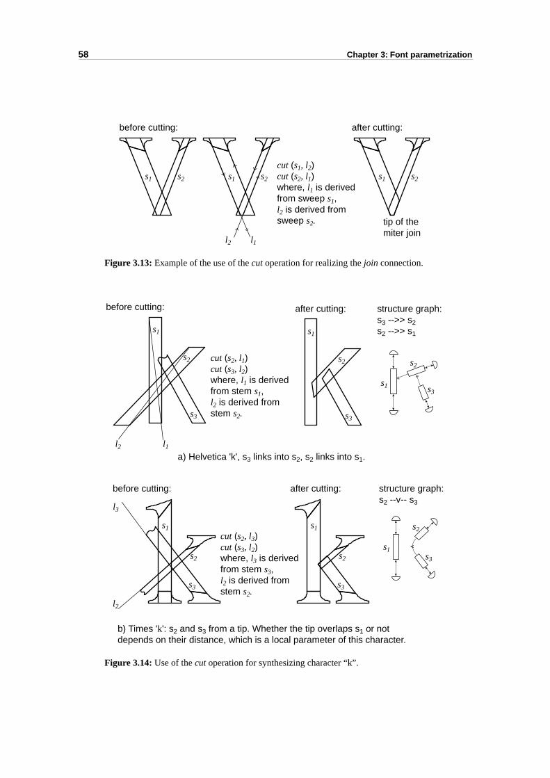
58 Chapter 3: Font parametrization
Figure 3.13: Example of the use of the cut operation for realizing the join connection.
Figure 3.14: Use of the cut operation for synthesizing character “k”.
s1 s2s1 s2 s1 s2
l1l2
cut (s1, l2)cut (s2, l1)where, l1 is derivedfrom sweep s1,l2 is derived fromsweep s2.
before cutting: after cutting:
tip of themiter join
v
s1
s1
s2 s2
s3
s3
s1
s2
s3
s1
s2
s3
s1
s2
s3
s1
s2
s3
l1
l3
l2
l2
cut (s2, l1)cut (s3, l2)where, l1 is derivedfrom stem s1, l2 is derived fromstem s2.
cut (s2, l3)cut (s3, l2)where, l3 is derivedfrom stem s3, l2 is derived fromstem s2.
after cutting: structure graph:s3 -->> s2s2 -->> s1
before cutting:
after cutting: structure graph:s2 --v-- s3
before cutting:
a) Helvetica 'k', s3 links into s2, s2 links into s1.
b) Times 'k': s2 and s3 from a tip. Whether the tip overlaps s1 or not depends on their distance, which is a local parameter of this character.
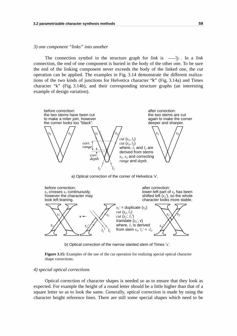
3.2 parametrizable character synthesis methods 59
e suree
ealiza-
sting
look asat of aing thed to be
3) one component “links” into another
The connection symbol in the structure graph for link is . In a linkconnection, the end of one component is buried in the body of the other one. To bthe end of the linking component never exceeds the body of the linked one, thcutoperation can be applied. The examples in Fig. 3.14 demonstrate the different rtions of the two kinds of junctions for Helvetica character “k” (Fig. 3.14a) and Timescharacter “k” (Fig. 3.14b), and their corresponding structure graphs (an intereexample of design variation).
Figure 3.15: Examples of the use of the cut operation for realizing special optical charactershape corrections.
4) special optical corrections
Optical correction of character shapes is needed so as to ensure that they expected. For example the height of a round letter should be a little higher than thsquare letter so as to look the same. Generally, optical correction is made by uscharacter height reference lines. There are still some special shapes which nee
corr.range
corr.depth
l2 l1
s1 s2 s1 s2s1 s2
cut (s1, l1)cut (s2, l2)where, l1 and l2 arederived from stemss1, s2 and correctingrange and depth.
s1
s2 s2'
s1
s2'
s2s2
l1l1'
s2' = duplicate (s2)cut (s2, l1)cut (s2', l1')translate (s2', v)where, l1 is derivedfrom stem s1, l1' = -l1.
v
a) Optical correction of the corner of Helvetica 'v'.
b) Optical correction of the narrow slanted stem of Times 'x'.
before correction:the two stems have been cutto make a miter join, howeverthe corner looks too "black".
after correction:the two stems are cutagain to make the cornerdeeper and sharper.
after correction:lower-left part of s2 has beenshifted left (s2'), so the wholecharacter looks more stable.
before correction:s2 crosses s1 continuously,however the character maylook left leaning.

60 Chapter 3: Font parametrization
sharpthind soe real-
nd theto be
somells theothing
ntoursthength of
arture
corner.cornerps the
optically corrected and are not subject to the reference lines. For example thecorner of Helvetica “v” (Fig. 3.15a) should be corrected to look really sharp, and the diagonal stroke in the cross junction of Times “x” (Fig. 3.15b) should be correctethat the character looks stable [Jamra93]. These special optical corrections can bized with the help of the cut operation.
3.2.3.2 Smooth corner of intersected components
The bulb/pear-like terminal may need to smooth the corner formed by the sweep adot. In some typefaces, corners formed by two straight component also need smoothed. We define the smooth boundary correction operation to fulfill this task. Thesmooth operation generates a smoothing shape from the two given components andsmoothing parameters (Fig. 3.16). A smoothing shape is a path component which ficorner smoothly. The size and shape of the smoothing shape are controlled by smoparameters. This operation first finds the corner by possibly intersecting the two cowhich form the corner. Then the smooth operation constructs a smoothing shape from parameters specifying the range of the corner to be smoothed and the tangent lethe smoothing curve.
Figure 3.16: Definition of the smooth operation.
In Fig. 3.16, smoothing parameter r1 and r2 limit the range of the corner to besmoothed by restricting the length of the two edges of the corner. Parameters s1 and s2control the curvature of the smoothing curve by the length of tangents at both depand arrival point. Tangent directions are computed by the smooth operation in order toensure smooth connection between the smoothing curve and the two edges of theThe final constructed smoothing shape should cover the smoothed area of the without leak. We can make sure the smoothing shape touches or slightly overla
smoothing curve
r1s1
s2
r2
corner
s1, s2: lengths of tangents at departure and arrival points of the smoothing curve;r1, r2: lengths of two edges of the corner, whichlimits the range of the corner to be smoothed.
smoothingshape to beadded to thecorner
smooth (contour1, contour2, r1, r2, s1, s2) ==> smoothing_shape
contour1
contour2
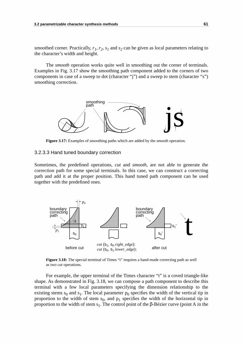
3.2 parametrizable character synthesis methods 61
to
als.of twoter “s”)
eectinge used
-likeribe this the
n
smoothed corner. Practically, r1, r2, s1 and s2 can be given as local parameters relatingthe character’s width and height.
The smooth operation works quite well in smoothing out the corner of terminExamples in Fig. 3.17 show the smoothing path component added to the corners components in case of a sweep to dot (character “j”) and a sweep to stem (characsmoothing correction.
Figure 3.17: Examples of smoothing paths which are added by the smooth operation.
3.2.3.3 Hand tuned boundary correction
Sometimes, the predefined operations, cut and smooth, are not able to generate thcorrection path for some special terminals. In this case, we can construct a corrpath and add it at the proper position. This hand tuned path component can btogether with the predefined ones.
Figure 3.18: The special terminal of Times “t” requires a hand-made correcting path as wellas two cut operations.
For example, the upper terminal of the Times character “t” is a coved triangleshape. As demonstrated in Fig. 3.18, we can compose a path component to descterminal with a few local parameters specifying the dimension relationship toexisting stems s0 and s1. The local parameter p0 specifies the width of the vertical tip inproportion to the width of stem s0, and p1 specifies the width of the horizontal tip iproportion to the width of stem s1. The control point of the β-Bézier curve (point A in the
smoothingpath
js
boundarycorrectingpath
boundarycorrectingpath
tA
s0
s1
s0'
s1'
cut (s1, s0.right_edge);cut (s0, s1.lower_edge);
p1
p0
before cut after cut
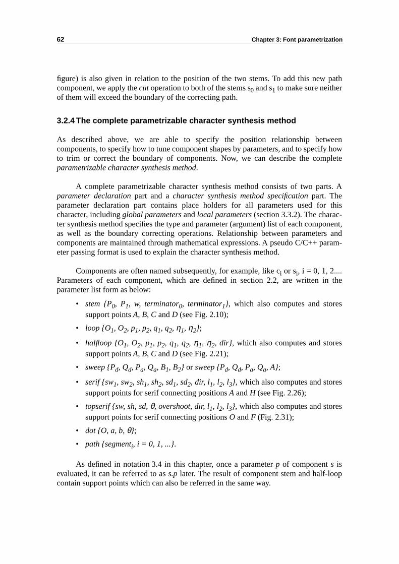
62 Chapter 3: Font parametrization
path
weenify howplete
rts. A
r this-ponent,rs andparam-
in the
s
s
s
s
op
figure) is also given in relation to the position of the two stems. To add this newcomponent, we apply the cut operation to both of the stems s0 and s1 to make sure neitherof them will exceed the boundary of the correcting path.
3.2.4 The complete parametrizable character synthesis method
As described above, we are able to specify the position relationship betcomponents, to specify how to tune component shapes by parameters, and to specto trim or correct the boundary of components. Now, we can describe the comparametrizable character synthesis method.
A complete parametrizable character synthesis method consists of two paparameter declaration part and a character synthesis method specification part. Theparameter declaration part contains place holders for all parameters used focharacter, including global parameters and local parameters (section 3.3.2). The character synthesis method specifies the type and parameter (argument) list of each comas well as the boundary correcting operations. Relationship between parametecomponents are maintained through mathematical expressions. A pseudo C/C++ eter passing format is used to explain the character synthesis method.
Components are often named subsequently, for example, like ci or si, i = 0, 1, 2....Parameters of each component, which are defined in section 2.2, are written parameter list form as below:
• stem {P0, P1, w, terminator0, terminator1}, which also computes and storesupport points A, B, C and D (see Fig. 2.10);
• loop {O1, O2, p1, p2, q1, q2, η1, η2};
• halfloop {O1, O2, p1, p2, q1, q2, η1, η2, dir}, which also computes and storesupport points A, B, C and D (see Fig. 2.21);
• sweep {Pd, Qd, Pa, Qa, B1, B2} or sweep {Pd, Qd, Pa, Qa, A};
• serif {sw1, sw2, sh1, sh2, sd1, sd2, dir, l1, l2, l3}, which also computes and storesupport points for serif connecting positions A and H (see Fig. 2.26);
• topserif {sw, sh, sd, θ, overshoot, dir, l1, l2, l3}, which also computes and storesupport points for serif connecting positions O and F (Fig. 2.31);
• dot {O, a, b, θ};
• path {segmenti, i = 0, 1, ...}.
As defined in notation 3.4 in this chapter, once a parameter p of component s isevaluated, it can be referred to as s.p later. The result of component stem and half-locontain support points which can also be referred in the same way.
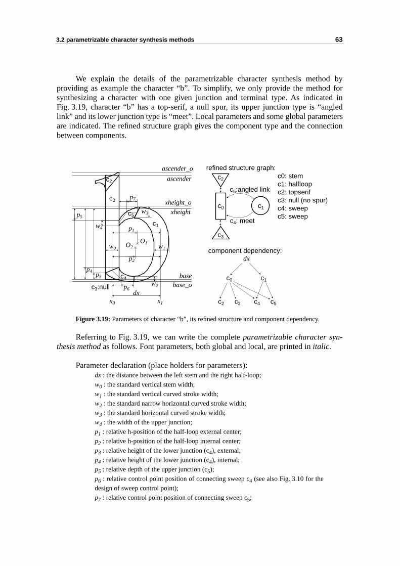
3.2 parametrizable character synthesis methods 63
d by ford ingledeters
nection
-
We explain the details of the parametrizable character synthesis methoproviding as example the character “b”. To simplify, we only provide the methodsynthesizing a character with one given junction and terminal type. As indicateFig. 3.19, character “b” has a top-serif, a null spur, its upper junction type is “anlink” and its lower junction type is “meet”. Local parameters and some global paramare indicated. The refined structure graph gives the component type and the conbetween components.
Figure 3.19: Parameters of character “b”, its refined structure and component dependency.
Referring to Fig. 3.19, we can write the complete parametrizable character synthesis method as follows. Font parameters, both global and local, are printed in italic.
Parameter declaration (place holders for parameters):dx : the distance between the left stem and the right half-loop;
w0 : the standard vertical stem width;
w1 : the standard vertical curved stroke width;
w2 : the standard narrow horizontal curved stroke width;
w3 : the standard horizontal curved stroke width;
w4 : the width of the upper junction;
p1 : relative h-position of the half-loop external center;
p2 : relative h-position of the half-loop internal center;
p3 : relative height of the lower junction (c4), external;
p4 : relative height of the lower junction (c4), internal;
p5 : relative depth of the upper junction (c5);
p6 : relative control point position of connecting sweep c4 (see also Fig. 3.10 for the
design of sweep control point);
p7 : relative control point position of connecting sweep c5;
c1
c1
c2c2
c0c0
c3
c4
c4: meetc5
c5:angled link
x0 x1
dx
ascender
xheight
basew2
w0 w1
w3
w4
ascender_o
xheight_o
base_o
O2O1
c0 c1
c5c4c2 c3
dx
c0: stemc1: halfloopc2: topserifc3: null (no spur)c4: sweepc5: sweep
refined structure graph:
component dependency:
p1
p7
p5
p4p3
p2
p6c3:null
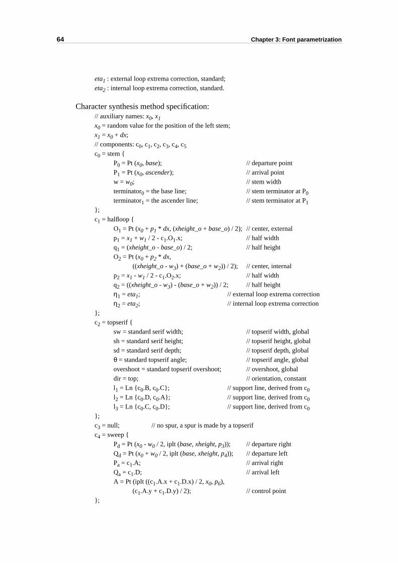
64 Chapter 3: Font parametrization
eta1 : external loop extrema correction, standard;
eta2 : internal loop extrema correction, standard.
Character synthesis method specification:// auxiliary names: x0, x1
x0 = random value for the position of the left stem;
x1 = x0 + dx;
// components: c0, c1, c2, c3, c4, c5
c0 = stem {
P0 = Pt (x0, base); // departure point
P1 = Pt (x0, ascender); // arrival point
w = w0; // stem width
terminator0 = the base line; // stem terminator at P0
terminator1 = the ascender line; // stem terminator at P1
};
c1 = halfloop {
O1 = Pt (x0 + p1 * dx, (xheight_o + base_o) / 2); // center, external
p1 = x1 + w1 / 2 - c1.O1.x; // half width
q1 = (xheight_o - base_o) / 2; // half height
O2 = Pt (x0 + p2 * dx,
((xheight_o - w3) + (base_o + w2)) / 2); // center, internal
p2 = x1 - w1 / 2 - c1.O2.x; // half width
q2 = ((xheight_o - w3) - (base_o + w2)) / 2; // half height
η1 = eta1; // external loop extrema correction
η2 = eta2; // internal loop extrema correction
};
c2 = topserif {
sw = standard serif width; // topserif width, global
sh = standard serif height; // topserif height, global
sd = standard serif depth; // topserif depth, global
θ = standard topserif angle; // topserif angle, global
overshoot = standard topserif overshoot; // overshoot, global
dir = top; // orientation, constant
l1 = Ln {c0.B, c0.C}; // support line, derived from c0
l2 = Ln {c0.D, c0.A}; // support line, derived from c0l3 = Ln {c0.C, c0.D}; // support line, derived from c0
};
c3 = null; // no spur, a spur is made by a topserif
c4 = sweep {
Pd = Pt (x0 - w0 / 2, iplt (base, xheight, p3)); // departure right
Qd = Pt (x0 + w0 / 2, iplt (base, xheight, p4)); // departure left
Pa = c1.A; // arrival right
Qa = c1.D; // arrival left
A = Pt (iplt ((c1.A.x + c1.D.x) / 2, x0, p6),
(c1.A.y + c1.D.y) / 2); // control point
};
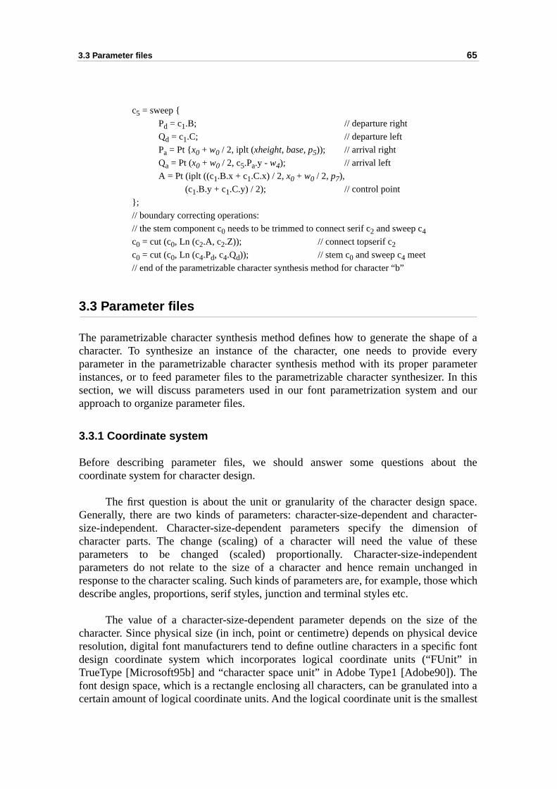
3.3 Parameter files 65
pe of a everyameter In thisd our
ut the
pace.racter-
ion ofthesendentged in
e which
of thedevicec font” inThed into aallest
c5 = sweep {
Pd = c1.B; // departure right
Qd = c1.C; // departure left
Pa = Pt {x0 + w0 / 2, iplt (xheight, base, p5)); // arrival right
Qa = Pt (x0 + w0 / 2, c5.Pa.y - w4); // arrival left
A = Pt (iplt ((c1.B.x + c1.C.x) / 2, x0 + w0 / 2, p7),
(c1.B.y + c1.C.y) / 2); // control point
};
// boundary correcting operations:
// the stem component c0 needs to be trimmed to connect serif c2 and sweep c4c0 = cut (c0, Ln (c2.A, c2.Z)); // connect topserif c2c0 = cut (c0, Ln (c4.Pd, c4.Qd)); // stem c0 and sweep c4 meet
// end of the parametrizable character synthesis method for character “b”
3.3 Parameter files
The parametrizable character synthesis method defines how to generate the shacharacter. To synthesize an instance of the character, one needs to provideparameter in the parametrizable character synthesis method with its proper parinstances, or to feed parameter files to the parametrizable character synthesizer.section, we will discuss parameters used in our font parametrization system anapproach to organize parameter files.
3.3.1 Coordinate system
Before describing parameter files, we should answer some questions abocoordinate system for character design.
The first question is about the unit or granularity of the character design sGenerally, there are two kinds of parameters: character-size-dependent and chasize-independent. Character-size-dependent parameters specify the dimenscharacter parts. The change (scaling) of a character will need the value of parameters to be changed (scaled) proportionally. Character-size-indepeparameters do not relate to the size of a character and hence remain unchanresponse to the character scaling. Such kinds of parameters are, for example, thosdescribe angles, proportions, serif styles, junction and terminal styles etc.
The value of a character-size-dependent parameter depends on the sizecharacter. Since physical size (in inch, point or centimetre) depends on physical resolution, digital font manufacturers tend to define outline characters in a specifidesign coordinate system which incorporates logical coordinate units (“FUnitTrueType [Microsoft95b] and “character space unit” in Adobe Type1 [Adobe90]). font design space, which is a rectangle enclosing all characters, can be granulatecertain amount of logical coordinate units. And the logical coordinate unit is the sm
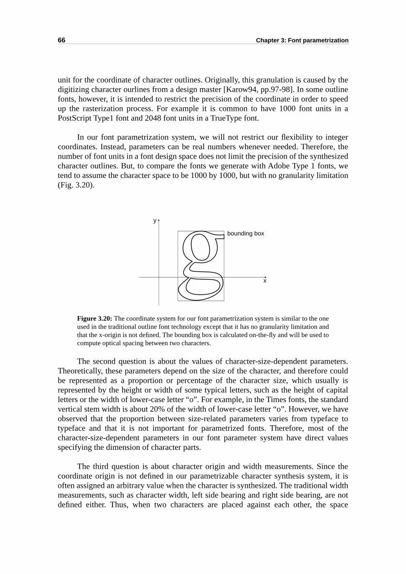
66 Chapter 3: Font parametrization
y thetline
speeds in a
erfore, thesized
ts, weitation
meters.e couldally isapital
ndardhaveace tof the values
e the, it is
l widthare not space
unit for the coordinate of character outlines. Originally, this granulation is caused bdigitizing character ourlines from a design master [Karow94, pp.97-98]. In some oufonts, however, it is intended to restrict the precision of the coordinate in order to up the rasterization process. For example it is common to have 1000 font unitPostScript Type1 font and 2048 font units in a TrueType font.
In our font parametrization system, we will not restrict our flexibility to integcoordinates. Instead, parameters can be real numbers whenever needed. Therenumber of font units in a font design space does not limit the precision of the synthecharacter outlines. But, to compare the fonts we generate with Adobe Type 1 fontend to assume the character space to be 1000 by 1000, but with no granularity lim(Fig. 3.20).
Figure 3.20: The coordinate system for our font parametrization system is similar to the oneused in the traditional outline font technology except that it has no granularity limitation andthat the x-origin is not defined. The bounding box is calculated on-the-fly and will be used tocompute optical spacing between two characters.
The second question is about the values of character-size-dependent paraTheoretically, these parameters depend on the size of the character, and thereforbe represented as a proportion or percentage of the character size, which usurepresented by the height or width of some typical letters, such as the height of cletters or the width of lower-case letter “o”. For example, in the Times fonts, the stavertical stem width is about 20% of the width of lower-case letter “o”. However, we observed that the proportion between size-related parameters varies from typeftypeface and that it is not important for parametrized fonts. Therefore, most ocharacter-size-dependent parameters in our font parameter system have directspecifying the dimension of character parts.
The third question is about character origin and width measurements. Sinccoordinate origin is not defined in our parametrizable character synthesis systemoften assigned an arbitrary value when the character is synthesized. The traditionameasurements, such as character width, left side bearing and right side bearing, defined either. Thus, when two characters are placed against each other, the
bounding box
x
y
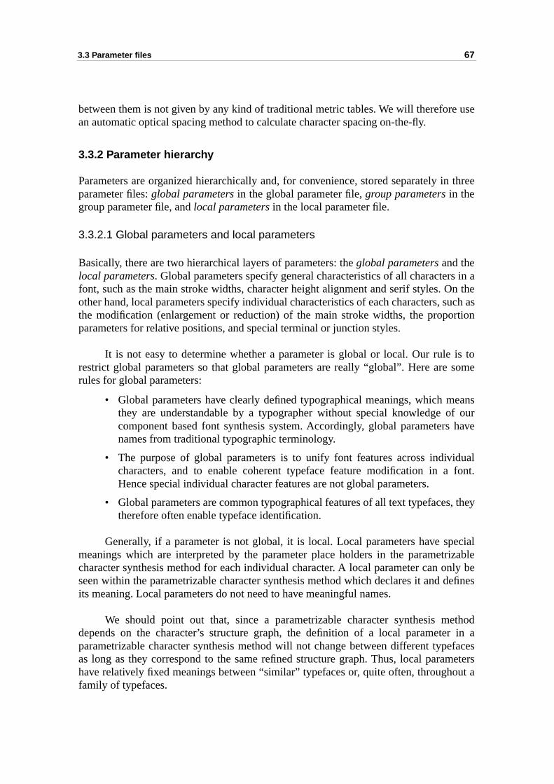
3.3 Parameter files 67
use
n three
s in aOn theuch asrtion
is to some
eansf our have
idual font.
, they
ecialrizablenly bedefines
ethodr in aefacesmeters
out a
between them is not given by any kind of traditional metric tables. We will thereforean automatic optical spacing method to calculate character spacing on-the-fly.
3.3.2 Parameter hierarchy
Parameters are organized hierarchically and, for convenience, stored separately iparameter files: global parameters in the global parameter file, group parameters in thegroup parameter file, and local parameters in the local parameter file.
3.3.2.1 Global parameters and local parameters
Basically, there are two hierarchical layers of parameters: the global parameters and thelocal parameters. Global parameters specify general characteristics of all characterfont, such as the main stroke widths, character height alignment and serif styles. other hand, local parameters specify individual characteristics of each characters, sthe modification (enlargement or reduction) of the main stroke widths, the propoparameters for relative positions, and special terminal or junction styles.
It is not easy to determine whether a parameter is global or local. Our rulerestrict global parameters so that global parameters are really “global”. Here arerules for global parameters:
• Global parameters have clearly defined typographical meanings, which mthey are understandable by a typographer without special knowledge ocomponent based font synthesis system. Accordingly, global parametersnames from traditional typographic terminology.
• The purpose of global parameters is to unify font features across indivcharacters, and to enable coherent typeface feature modification in aHence special individual character features are not global parameters.
• Global parameters are common typographical features of all text typefacestherefore often enable typeface identification.
Generally, if a parameter is not global, it is local. Local parameters have spmeanings which are interpreted by the parameter place holders in the parametcharacter synthesis method for each individual character. A local parameter can oseen within the parametrizable character synthesis method which declares it and its meaning. Local parameters do not need to have meaningful names.
We should point out that, since a parametrizable character synthesis mdepends on the character’s structure graph, the definition of a local parameteparametrizable character synthesis method will not change between different typas long as they correspond to the same refined structure graph. Thus, local parahave relatively fixed meanings between “similar” typefaces or, quite often, throughfamily of typefaces.

68 Chapter 3: Font parametrization
ot alln beed to
r groupupingto have
value
port
th ofroup foraturend qe loop,hese
nds ofions of
r jobs vary
3.3.2.2 Local parameter grouping
Sometimes a typographic feature is similar within a group of characters, but ncharacters in a font. The local parameters controlling such kind of features cagrouped in order to achieve coherent feature modification. The parameter usrepresent a group of coherent local parameters is called a group parameter.
Parameters which can be grouped and the characters affected by a parameteare not fixed for different typefaces. Therefore, a mechanism allowing dynamic groof parameters has been introduced. This mechanism enables the parameter files the following two functions:
1. name definition - to define a name for a group parameter and to associate a to the defined name;
2. name reference - to refer to the value of a predefined name and to offer supfor simple algebra operations (add, subtract, multiply, divide etc.).
For example, we can define a group parameter to control the junction depcharacter h, m, n and u, because they have similar arches. We can also define a gthe relative position of the extrema of the arch and the relative position of the curvcontrol point for this group of characters (Fig. 3.21a). Similarly, characters b, d, p ahave some coherent features which can be grouped, such as stress (slant) of thloop-stem connecting position and connecting sweep curvature (Fig. 3.21b). Tgroups are common in many serif and sans-serif typefaces. By grouping these kifeature controlling parameters, we are able to generate coherent feature modificata group of characters (Fig. 3.22).
Figure 3.21: An example of features which can be controlled by group parameters: (a) thearches of characters h, m, n, and u; (b) the round parts of characters b, d, p and q.
Coherent feature modification is quite useful for typographers because theiare not only to design completely new typefaces but also to modify, improve or
b p d qh A
xheight
junc
tion
dept
h
A
junc
tion
dept
h
base
xheight
base
xheight
base
junctiondepth
(a)
(b)
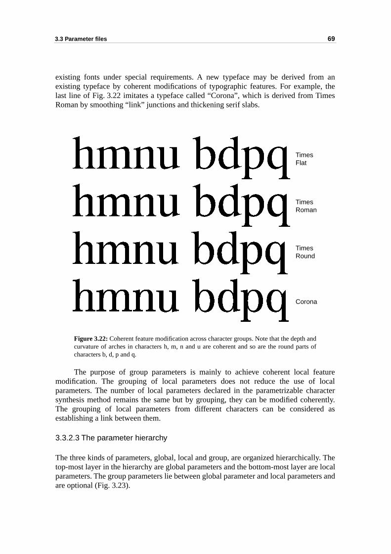
3.3 Parameter files 69
m ane, themes
f
aturelocalaracterrently.
ed as
ly. Thee localters and
existing fonts under special requirements. A new typeface may be derived froexisting typeface by coherent modifications of typographic features. For exampllast line of Fig. 3.22 imitates a typeface called “Corona”, which is derived from TiRoman by smoothing “link” junctions and thickening serif slabs.
Figure 3.22: Coherent feature modification across character groups. Note that the depth andcurvature of arches in characters h, m, n and u are coherent and so are the round parts ocharacters b, d, p and q.
The purpose of group parameters is mainly to achieve coherent local femodification. The grouping of local parameters does not reduce the use of parameters. The number of local parameters declared in the parametrizable chsynthesis method remains the same but by grouping, they can be modified coheThe grouping of local parameters from different characters can be considerestablishing a link between them.
3.3.2.3 The parameter hierarchy
The three kinds of parameters, global, local and group, are organized hierarchicaltop-most layer in the hierarchy are global parameters and the bottom-most layer arparameters. The group parameters lie between global parameter and local parameare optional (Fig. 3.23).
TimesFlat
TimesRoman
TimesRound
Corona
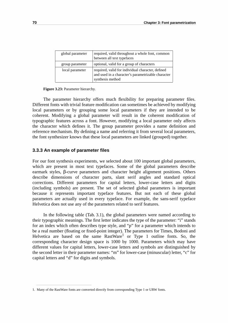
70 Chapter 3: Font parametrization
les.yingto be offfectsn andeters,
er.
eters,scribethersopticaldigitsortantglobalpeface
ng totandsds toi and
y haveed byc” for
Figure 3.23: Parameter hierarchy.
The parameter hierarchy offers much flexibility for preparing parameter fiDifferent fonts with trivial feature modification can sometimes be achieved by modiflocal parameters or by grouping some local parameters if they are intended coherent. Modifying a global parameter will result in the coherent modificationtypographic features across a font. However, modifying a local parameter only athe character which defines it. The group parameter provides a name definitioreference mechanism. By defining a name and referring it from several local paramthe font synthesizer knows that these local parameters are linked (grouped) togeth
3.3.3 An example of parameter files
For our font synthesis experiments, we selected about 100 important global paramwhich are present in most text typefaces. Some of the global parameters deearmark styles, β-curve parameters and character height alignment positions. Odescribe dimensions of character parts, slant serif angles and standard corrections. Different parameters for capital letters, lower-case letters and (including symbols) are present. The set of selected global parameters is impbecause it represents important typeface features. But not each of these parameters are actually used in every typeface. For example, the sans-serif tyHelvetica does not use any of the parameters related to serif features.
In the following table (Tab. 3.1), the global parameters were named accorditheir typographic meanings. The first letter indicates the type of the parameter: “i” sfor an index which often describes type style, and “p” for a parameter which intenbe a real number (floating or fixed-point integer). The parameters for Times, BodonHelvetica are based on the same RastWare1 or Type 1 outline fonts. So, thecorresponding character design space is 1000 by 1000. Parameters which madifferent values for capital letters, lower-case letters and symbols are distinguishthe second letter in their parameter names: “m” for lower-case (minuscular) letter, “capital letters and “d” for digits and symbols.
1. Many of the RastWare fonts are converted directly from corresponding Type 1 or URW fonts.
global parameter required, valid throughout a whole font, common between all text typefaces
group parameter optional, valid for a group of characters
local parameter required, valid for individual character, defined and used in a character’s parametrizable character synthesis method
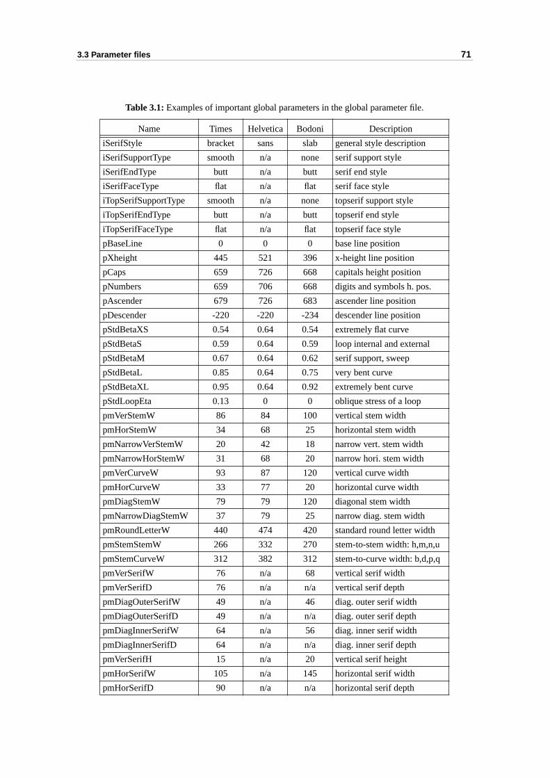
3.3 Parameter files 71
Table 3.1: Examples of important global parameters in the global parameter file.
Name Times Helvetica Bodoni Description
iSerifStyle bracket sans slab general style description
iSerifSupportType smooth n/a none serif support style
iSerifEndType butt n/a butt serif end style
iSerifFaceType flat n/a flat serif face style
iTopSerifSupportType smooth n/a none topserif support style
iTopSerifEndType butt n/a butt topserif end style
iTopSerifFaceType flat n/a flat topserif face style
pBaseLine 0 0 0 base line position
pXheight 445 521 396 x-height line position
pCaps 659 726 668 capitals height position
pNumbers 659 706 668 digits and symbols h. pos.
pAscender 679 726 683 ascender line position
pDescender -220 -220 -234 descender line position
pStdBetaXS 0.54 0.64 0.54 extremely flat curve
pStdBetaS 0.59 0.64 0.59 loop internal and external
pStdBetaM 0.67 0.64 0.62 serif support, sweep
pStdBetaL 0.85 0.64 0.75 very bent curve
pStdBetaXL 0.95 0.64 0.92 extremely bent curve
pStdLoopEta 0.13 0 0 oblique stress of a loop
pmVerStemW 86 84 100 vertical stem width
pmHorStemW 34 68 25 horizontal stem width
pmNarrowVerStemW 20 42 18 narrow vert. stem width
pmNarrowHorStemW 31 68 20 narrow hori. stem width
pmVerCurveW 93 87 120 vertical curve width
pmHorCurveW 33 77 20 horizontal curve width
pmDiagStemW 79 79 120 diagonal stem width
pmNarrowDiagStemW 37 79 25 narrow diag. stem width
pmRoundLetterW 440 474 420 standard round letter width
pmStemStemW 266 332 270 stem-to-stem width: h,m,n,u
pmStemCurveW 312 382 312 stem-to-curve width: b,d,p,q
pmVerSerifW 76 n/a 68 vertical serif width
pmVerSerifD 76 n/a n/a vertical serif depth
pmDiagOuterSerifW 49 n/a 46 diag. outer serif width
pmDiagOuterSerifD 49 n/a n/a diag. outer serif depth
pmDiagInnerSerifW 64 n/a 56 diag. inner serif width
pmDiagInnerSerifD 64 n/a n/a diag. inner serif depth
pmVerSerifH 15 n/a 20 vertical serif height
pmHorSerifW 105 n/a 145 horizontal serif width
pmHorSerifD 90 n/a n/a horizontal serif depth
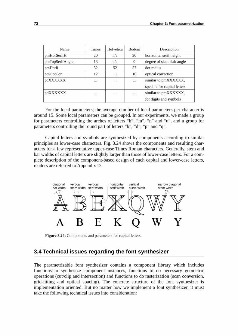
72 Chapter 3: Font parametrization
cter isa group for
imilarg char-em and com-letters,
ludesmetricrsion,
er ismust
For the local parameters, the average number of local parameters per charaaround 15. Some local parameters can be grouped. In our experiments, we made for parameters controlling the arches of letters “h”, “m”, “n” and “u”, and a groupparameters controlling the round part of letters “b”, “d”, “p” and “q”.
Capital letters and symbols are synthesized by components according to sprinciples as lower-case characters. Fig. 3.24 shows the components and resultinacters for a few representative upper-case Times Roman characters. Generally, stbar widths of capital letters are slightly larger than those of lower-case letters. For aplete description of the component-based design of each capital and lower-case readers are referred to Appendix D.
Figure 3.24: Components and parameters for capital letters.
3.4 Technical issues regarding the font synthesizer
The parametrizable font synthesizer contains a component library which incfunctions to synthesize component instances, functions to do necessary geooperations (cut/clip and intersection) and functions to do rasterization (scan convegrid-fitting and optical spacing). The concrete structure of the font synthesizimplementation oriented. But no matter how we implement a font synthesizer, it take the following technical issues into consideration:
pmHorSerifH 20 n/a 20 horizontal serif height
pmTopSerifAngle 13 n/a 0 degree of slant slab angle
pmDotR 52 52 57 dot radius
pmOptCor 12 11 10 optical correction
pcXXXXXX ... ... ... similar to pmXXXXXX,
specific for capital letters
pdXXXXXX ... ... ... similar to pmXXXXXX,
for digits and symbols
Name Times Helvetica Bodoni Description
diagonalbar width
verticalstem width
verticalserif width
horizontalserif width
verticalcurve width
narrow diagonalstem width
3.4 Technical issues regarding the font synthesizer 73
ter iss in
beay beses
ineethodthe
tion
ing aonently,
tantring,fonttored
etric verys forsizedn be
gy of font font
ation
ith a
ule
1. Grid-fitting for rasterization purpose: The actual physical size of a characthe result of scaling of parameters in respect to the device resolution. Atraditional outline font technology, intelligent grid-fitting (or hinting) should applied when the size of characters is small, because rounding effects mdetrimental to character quality. Traditional outline technology usually uconsiderable additional information called hints to improve fitting of outlcharacters to the target grid. Our parametrizable character synthesis malready includes the necessary information for grid-fitting, therefore overhead (time and storage) for grid-fitting with our font parametrizasystem should not be noticeable.
2. Flexible scan conversion: Scan conversion is the process of convertgeometric outline into pixels for raster devices. It can be based on compoutlines provided that the filling rule1 enables shape overlapping. Alternateone can merge component outlines to a traditional outline font.
3. Automatic metric table calculation: The metric table contains imporinformation for optical spacing of character pairs such as left-side bearight-side bearing, character width and character pair kerning. In a parametrization system, none of these typesetting information should be spermanently. Instead, they will automatically be calculated on-the-fly.
4. Specific geometric operation algorithms: Since general purpose geomoperation algorithms, for example intersection of two arbitrary shapes, arecomplex and hence not efficient, we intend to design specific algorithmshape merging and trimming. Fortunately, the shape of a synthecomponent is more or less known and therefore simplified algorithms caapplied, reducing their complexity and accelerating their speed.
5. Font organization: This is an almost stand-alone topic beyond the technolofont parametrization. But, some issues still need to be considered by thesynthesizer, such as composing hybrid characters and providing someinformation necessary for font management including font name, font creand modification date, copyright, etc.
In chapter 4, we will present some important algorithms and solutions along wdetailed description of our experimental font parametrization system.
1. Readers are referred to the PostScript language for an explanation of filling rules. The “non-zero winding” rensures that pixels in the overlapped area are activated.
74 Chapter 3: Font parametrization
fontparts:
ters byitives -ts. Weesign
izable globalontroln off local
mpleout the
3.5 Summary
This chapter presented concepts and methods of our component-basedparametrization system. The framework of the system consists of two main parametrizable character synthesis methods and parameter files.
The parametrizable character synthesis methods enable synthesizing characparametrizable components. Characters are built by using predefined shape primcomponents, and by specifying the relationships (dependency) between componenintroduced variations of terminals and junctions in order to cover a large character dspace.
The parameter files provide instances of parameters for the parametrcharacter synthesis methods. Parameters have been organized hierarchically:parameters control uniform features over the whole font and local parameters conly features of individual characters. To achieve coherent feature modificatiosimilar typographical parts across several characters, we introduced the concept oparameter grouping.
To explain in detail the parametrizable character synthesis system, a full exafor one character and its parameters have been given in this chapter. Statistics abnumber of required parameters are provided in section 4.6.
4.1 Classes 75
le
in ourchy ofer (seeof thections
tion,caling
ing ofhensivefirstesign ahical
ethod text ister files
elvesrch. Weation
cter’st whichrizableethod
helps
CHAPTER 4
Implementation of the parametrizabfont synthesizing system
In the previous chapter, we have presented the algorithms and techniques usedparametrizable character synthesis system and the specification of the hierarglobal, group and local parameters. In this chapter, focusing on the font synthesizthe system framework in Fig. 3.1), we describe our experimental implementation parametrizable font synthesizing system. The font synthesizer contains a set of funwhich deal with component synthesizing (building), parameter file interpretaspecific geometric operations such as shape trimming and merging, intelligent s(hinting), and automatic optical spacing.
We started our study on basic font parametrization problems, such as modellcurves and shape primitives for character parts. We used Mathematica, a compretool suitable for building mathematics and computation models. After the experimenting and prototyping phase, we decided to integrate the results and to dprototype system. This prototype system allows to carry out more typograpexperiments and to evaluate the results.
The font synthesizer and the individual parametrizable character synthesis mare written in C++. The parameter files, however, are written as readable text. Thisparsed and interpreted by the synthesizer. The readable and editable paramefacilitate the creation of derived fonts by appropriately modifying the parameters.
The problems of hinting and automatic optical spacing [Hersch95] are themstwo stand-alone research topics. They are outside the scope of the present reseahave however tried to adapt results from previous work into our font parametrizsystem. We also have slightly improved the technique used for automatic spacing.
4.1 Classes
There are some similarities in the data and in the behaviour of each charaparametrizable character synthesis method. This suggests designing a base objeccontains all the common data elements and functions used by each parametcharacter synthesis method. Each parametrizable character synthesis mcorresponds to an individual derived object of this base class. This model alsoimplementing the parameter hierarchy (Fig. 4.1).
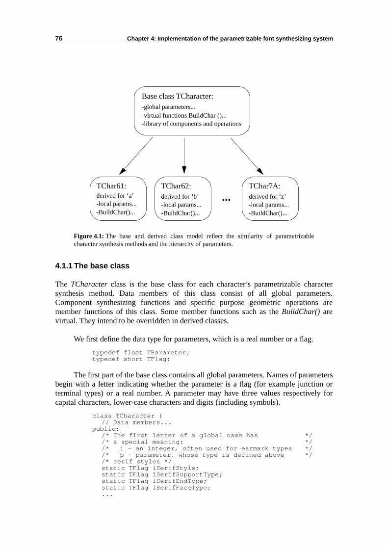
76 Chapter 4: Implementation of the parametrizable font synthesizing system
ractereters.s are
metersn orly for
Figure 4.1: The base and derived class model reflect the similarity of parametrizablecharacter synthesis methods and the hierarchy of parameters.
4.1.1 The base class
The TCharacter class is the base class for each character’s parametrizable chasynthesis method. Data members of this class consist of all global paramComponent synthesizing functions and specific purpose geometric operationmember functions of this class. Some member functions such as the BuildChar() arevirtual. They intend to be overridden in derived classes.
We first define the data type for parameters, which is a real number or a flag.
typedef float TParameter;typedef short TFlag;
The first part of the base class contains all global parameters. Names of parabegin with a letter indicating whether the parameter is a flag (for example junctioterminal types) or a real number. A parameter may have three values respectivecapital characters, lower-case characters and digits (including symbols).
class TCharacter {// Data members...
public:/* The first letter of a global name has *//* a special meaning: *//* i - an integer, often used for earmark types *//* p - parameter, whose type is defined above *//* serif styles */static TFlag iSerifStyle;static TFlag iSerifSupportType;static TFlag iSerifEndType; static TFlag iSerifFaceType;...
TChar62:
-local params...-BuildChar()...
derived for ‘b’
TChar61:
-local params...-BuildChar()...
derived for ‘a’
Base class TCharacter:-global parameters...-virtual functions BuildChar ()...-library of components and operations
TChar7A:
-local params...-BuildChar()...
derived for ‘z’...
4.1 Classes 77
sizingesults.
in
n alsonction
/* global parameter names: ****************************//* a name is like: p(c/m/d)Xxxx...xxx(W/H/D/A) ******//* where, c - capital, m - minuscule, d - digit *****//******************************************************//* reference lines -----------------------------------*/static TParameter pBaseLine;static TParameter pXheight;.../* beta ----------------------------------------------*/static TParameter pBestBeta;...static TParameter pLoopExternalBeta;static TParameter pLoopInternalBeta;.../* stem ----------------------------------------------*/static TParameter pcVerStemW, pmVerStemW, pdVerStemW;static TParameter pcHorStemW, pmHorStemW, pdHorStemW;.../* character width -----------------------------------*/static TParameter pcRoundLetterW, pmRoundLetterW, pdRo...;static TParameter pcStemStemW, pmStemStemW, pdStemStemW;static TParameter pcStemCurveW, pmStemCurveW, pdStemCurveW;/*serif ----------------------------------------------*/static TParameter pcVerSerifW, pmVerSerifW, pdVerSerifW;static TParameter pcVerSerifD, pmVerSerifD, pdVerSerifD;static TParameter pcVerSerifH, pmVerSerifH, pdVerSerifH;.../* others --------------------------------------------*/static TParameter pcOptCor, pmOptCor, pdOptCor;.../* spacing -------------------------------------------*/static TParameter pCapitalSpacing;static TParameter pSmallSpacing;.../* end of global parameters ***************************/
The second part of the base class mainly contains functions for synthecomponents and functions for inputting parameters and handling synthesized rComponents are stored in a list written as s[] . The data member theGlyph holds the resultof BuildChar (), and theMergedGlyph holds the result after merging all componentstheGlyph. Both of these results (contours) are stored in global memory.
protected:TComponent s[kMaxNbOfComponents];TGlyph theGlyph;TGlyph theMergedGlyph;
The constructor of the class is supposed to initialize the parameters. One caupdate the parameters or write parameters to a file by calling the corresponding futo load or write a parameter file.
// Member functionspublic:
TCharacter ();virtual ~TCharacter ();
public:static void LoadGlobalParameters (FILE *fp);static void LoadGroupParameters (FILE *fp);virtual void LoadLocalParameters (FILE *fp);static void WriteGlobalParameters (FILE *fp);static void WriteGroupParameters (FILE *fp);
78 Chapter 4: Implementation of the parametrizable font synthesizing system
nctionion
ass.
ts forctionr
ss. They
s all
virtual void WriteLocalParameters (FILE *fp);
The parametrizable character synthesis method is represented by a fuBuildChar (), which will be overridden for each individual characters. The functUnBuildChar () frees memory when the object is destroyed.
virtual void BuildChar ();virtual void UnBuildChar ();
A function for synthesizing a component is named as makeXxxx (), which createsan TComponent object (see section 4.1.3).
protected:TComponent nullComponent ();TComponent makeStem (TRealPoint p0, TRealPoint p1,
float w, int end0, int end1);TComponent makeSerif (float sw1, float sh1, float sd1,
float sw2, float sh2, float sd2,TLine l1, TLine l2, TLine l3, int dir);
TComponent makeTopSerif (float sw, float sh, float sd,float theta, float overshoot, TLine l1, TLine l2, TLine l3, int dir);
TComponent makeSweep (TRealPoint Pd, TRealPoint Qd,TRealPoint Pa, TRealPoint Qa,TRealPoint B1, TRealPoint B2);
TComponent makeLoop (TRealPoint center1,float a1, float b1, float eta1, RealPoint center2,float a2, float b2, float eta2);
TComponent makeHalfLoop (TRealPoint center1,float a1, float b1, float eta1, TealPoint center2,float a2, float b2, float eta2, int dir);
TComponent makeDot (TRealPoint center,float a, float b, float theta);
Operations specific for components are also member functions of the base cl
TContour cut (TContour theContour, TLine theLine);TContour unite (TContour cont1, TContour cont2);TContour smooth (TContour cont1, TContour cont2,
float r1, float r2, float tang1, float tang2);
There are some functions for handling outputs, such as preparing drawing lisdisplaying the components and character glyphs. Among them, the funMergeGlyphShapes () merges components in theGlyph into a non-overlapping characteoutline and stores it in theMergeGlyphShape.
void MergeGlyphShapes ();...
}; // end of the base class TCharacter
4.1.2 The derived classes
Each parametrizable character synthesis method is a derived class of the base claare named according to their ASCII code with a prefix “TChar”. For example the classfor character “a” is named as “TChar61”, the class for character “z” is named a“TChar7A”, etc. Generally the TCharXX class has two parts. The first part declaresthe parameters used by this character specification.
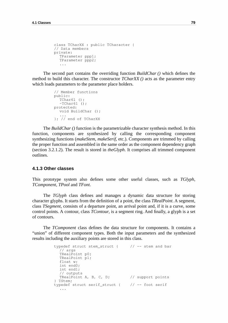
4.1 Classes 79
y
thisonentg
cy grapht
oring
omeet
ns asized
class TCharXX : public TCharacter {// Data membersprivate:
TParameter ppp1;TParameter ppp2;...
The second part contains the overriding function BuildChar () which defines themethod to build this character. The constructor TCharXX () acts as the parameter entrwhich loads parameters to the parameter place holders.
// Member functionspublic:
TChar61 ();~TChar61 ();
protected:void BuildChar ();...
}; // end of TCharXX
The BuildChar () function is the parametrizable character synthesis method. Infunction, components are synthesized by calling the corresponding compsynthesizing functions (makeStem, makeSerif, etc.). Components are trimmed by callinthe proper function and assembled in the same order as the component dependen(section 3.2.1.2). The result is stored in theGlyph. It comprises all trimmed componenoutlines.
4.1.3 Other classes
This prototype system also defines some other useful classes, such as TGlyph,TComponent, TPool and TFont.
The TGlyph class defines and manages a dynamic data structure for stcharacter glyphs. It starts from the definition of a point, the class TRealPoint. A segment,class TSegment, consists of a departure point, an arrival point and, if it is a curve, scontrol points. A contour, class TContour, is a segment ring. And finally, a glyph is a sof contours.
The TComponent class defines the data structure for components. It contai“union” of different component types. Both the input parameters and the syntheresults including the auxiliary points are stored in this class.
typedef struct stem_struct { // -- stem and bar// argsTRealPoint p0;TRealPoint p1;float w;int end0;int end1;// outputsTRealPoint A, B, C, D; // support points
} TStem;typedef struct serif_struct { // -- foot serif
...
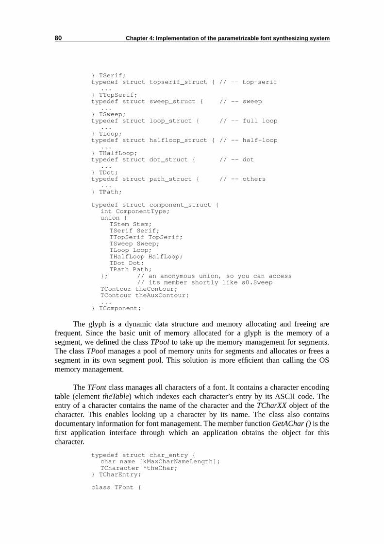
80 Chapter 4: Implementation of the parametrizable font synthesizing system
areof a
nts.ees a OS
oding
ntains
this
} TSerif;typedef struct topserif_struct { // -- top-serif
...} TTopSerif;typedef struct sweep_struct { // -- sweep
...} TSweep;typedef struct loop_struct { // -- full loop
...} TLoop;typedef struct halfloop_struct { // -- half-loop
...} THalfLoop;typedef struct dot_struct { // -- dot
...} TDot;typedef struct path_struct { // -- others
...} TPath;
typedef struct component_struct {int ComponentType;union {
TStem Stem;TSerif Serif;TTopSerif TopSerif;TSweep Sweep;TLoop Loop;THalfLoop HalfLoop;TDot Dot;TPath Path;
}; // an anonymous union, so you can access// its member shortly like s0.Sweep
TContour theContour;TContour theAuxContour;...
} TComponent;
The glyph is a dynamic data structure and memory allocating and freeingfrequent. Since the basic unit of memory allocated for a glyph is the memory segment, we defined the class TPool to take up the memory management for segmeThe class TPool manages a pool of memory units for segments and allocates or frsegment in its own segment pool. This solution is more efficient than calling thememory management.
The TFont class manages all characters of a font. It contains a character enctable (element theTable) which indexes each character’s entry by its ASCII code. Theentry of a character contains the name of the character and the TCharXX object of thecharacter. This enables looking up a character by its name. The class also codocumentary information for font management. The member function GetAChar () is thefirst application interface through which an application obtains the object for character.
typedef struct char_entry {char name [kMaxCharNameLength];TCharacter *theChar;
} TCharEntry;
class TFont {
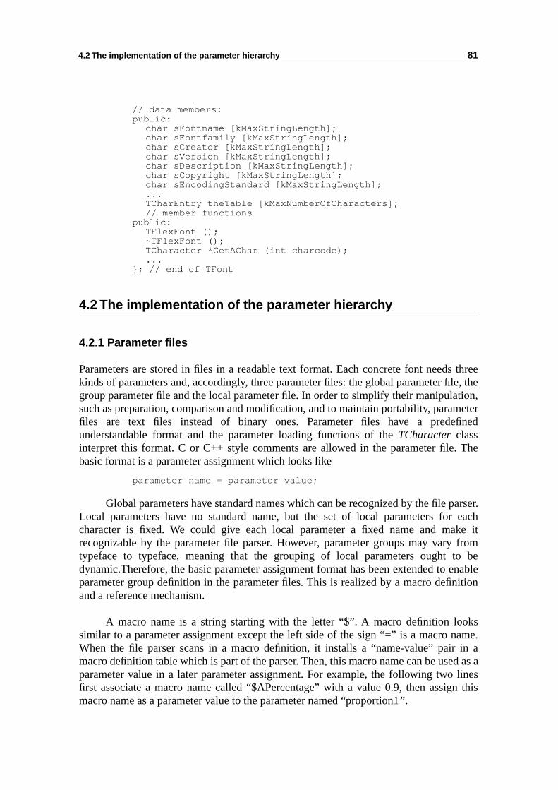
4.2 The implementation of the parameter hierarchy 81
s threele, thetion,meter
efined
. The
parser.r eachake it from
to be enablenition
oksname. in aed as a linesn this
// data members:public:
char sFontname [kMaxStringLength]; char sFontfamily [kMaxStringLength];char sCreator [kMaxStringLength];char sVersion [kMaxStringLength];char sDescription [kMaxStringLength];char sCopyright [kMaxStringLength];char sEncodingStandard [kMaxStringLength];...TCharEntry theTable [kMaxNumberOfCharacters];// member functions
public:TFlexFont ();~TFlexFont ();TCharacter *GetAChar (int charcode);...
}; // end of TFont
4.2 The implementation of the parameter hierarchy
4.2.1 Parameter files
Parameters are stored in files in a readable text format. Each concrete font needkinds of parameters and, accordingly, three parameter files: the global parameter figroup parameter file and the local parameter file. In order to simplify their manipulasuch as preparation, comparison and modification, and to maintain portability, parafiles are text files instead of binary ones. Parameter files have a predunderstandable format and the parameter loading functions of the TCharacter classinterpret this format. C or C++ style comments are allowed in the parameter filebasic format is a parameter assignment which looks like
parameter_name = parameter_value;
Global parameters have standard names which can be recognized by the fileLocal parameters have no standard name, but the set of local parameters focharacter is fixed. We could give each local parameter a fixed name and mrecognizable by the parameter file parser. However, parameter groups may varytypeface to typeface, meaning that the grouping of local parameters ought dynamic.Therefore, the basic parameter assignment format has been extended toparameter group definition in the parameter files. This is realized by a macro defiand a reference mechanism.
A macro name is a string starting with the letter “$”. A macro definition losimilar to a parameter assignment except the left side of the sign “=” is a macro When the file parser scans in a macro definition, it installs a “name-value” pairmacro definition table which is part of the parser. Then, this macro name can be usparameter value in a later parameter assignment. For example, the following twofirst associate a macro name called “$APercentage” with a value 0.9, then assigmacro name as a parameter value to the parameter named “proportion1” .
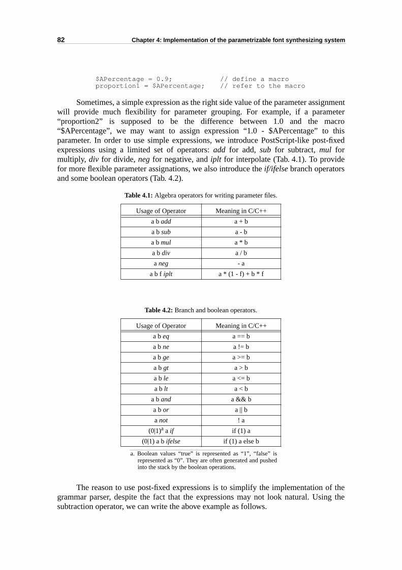
82 Chapter 4: Implementation of the parametrizable font synthesizing system
nmentteracro thist-fixed
f theng the
$APercentage = 0.9; // define a macroproportion1 = $APercentage; // refer to the macro
Sometimes, a simple expression as the right side value of the parameter assigwill provide much flexibility for parameter grouping. For example, if a parame“proportion2” is supposed to be the difference between 1.0 and the m“$APercentage”, we may want to assign expression “1.0 - $APercentage” toparameter. In order to use simple expressions, we introduce PostScript-like posexpressions using a limited set of operators: add for add, sub for subtract, mul formultiply, div for divide, neg for negative, and iplt for interpolate (Tab. 4.1). To providefor more flexible parameter assignations, we also introduce the if/ifelse branch operatorsand some boolean operators (Tab. 4.2).
Table 4.1: Algebra operators for writing parameter files.
Table 4.2: Branch and boolean operators.
The reason to use post-fixed expressions is to simplify the implementation ogrammar parser, despite the fact that the expressions may not look natural. Usisubtraction operator, we can write the above example as follows.
a. Boolean values “true” is represented as “1”, “false” isrepresented as “0”. They are often generated and pushedinto the stack by the boolean operations.
Usage of Operator Meaning in C/C++
a b add a + b
a b sub a - b
a b mul a * b
a b div a / b
a neg - a
a b f iplt a * (1 - f) + b * f
Usage of Operator Meaning in C/C++
a b eq a == b
a b ne a != b
a b ge a >= b
a b gt a > b
a b le a <= b
a b lt a < b
a b and a && b
a b or a || b
a not ! a
(0|1)a a if if (1) a
(0|1) a b ifelse if (1) a else b
4.2 The implementation of the parameter hierarchy 83
roupherent
21). those
er filesgroupoupos are
eteris of
G, weacro
d theed
holdsstalled) searchsame
rand ited inor, from
hed oned)out the
proportion2 = 1.0 $APercentage sub; // 1 - &APercentage
Now, let us present the method to link several local parameters into a gparameter. For example, we want to define a group parameter to achieve the comodification of the arch depth of characters “h”, “m”, “n” and “u” (see also Fig. 3.We can define a macro name “$ArchDepth” and then refer to that macro name incharacters.
Since the macro name must be defined before it is referred to, the parametshould be loaded in a fixed order: first the global parameters file, then the parameter definition file and finally the local parameter file. Modifying the grparameter file requires reloading both the group parameter file where the macrdefined and the local parameter file where the macros are referred to.
The flexible format of parameter files also provides a way to specify paramvarying rules in order to make typeface variation. Experiments on the synthesderived font by modifying parameters are presented in section 5.2.1. In Appendix give the complete global, group and local parameter files for Times Roman with a mdefined for applying boldness variation.
4.2.2 Implementation
The macro definition and reference mechanism is realized by a table calleMacroTable, which is functionally similar to the PostScript dictionary. The post-fixexpressions are implemented by a stack called the OperandStack, which is a simplifiedversion of the operand stack in a PostScript interpreter.
The macro definition and reference mechanism is realized by a table which name-value pairs. To define a macro, the macro name and values are stored (ininto the table. To reference (or use) a macro, the macro name is used as a key tothe table until it finds the most recently installed name-value pair which has the macro name. The value is returned to replace the macro’s name.
To process a post-fix expression, the parameter file parser pushes each opemeets into the OperandStack until it comes across an operator name. These are definTab. 4.1 and Tab. 4.2. Then the parser pops the operands required by the operatthe OperandStack. The binary operators add, sub, mul and div require two operands, theunary operator neg requires one operand, and the interpolation operator iplt requiresthree operands. The boolean operand for the branch operators if and ifelse is treatedaccording to this rule: value 0 means false, value 1 means true. After executing thefunction of the operator, the result is an operand ready for the next operation, pustop of the OperandStack. The end-of-line character (any comments will be skippindicates the end of the expression and the parameter file parser knows to pop latest operand as the result value of the expression. Then the OperandStack should beempty again as it was before parsing the expression.
84 Chapter 4: Implementation of the parametrizable font synthesizing system
makerted to
ecause
aps, forrocess “flag-
ourspping
pport
, seeardedes, aning the
4.3 Output forms of synthesized characters
Typographic characters are first synthesized as a set of trimmed components. Touse of them in an application, the synthesized characters can either be convedisplayable bitmaps, or to outlines in order to synthesize traditional outline fonts.
In both cases, the character is scaled just by scaling the global parameters, ball local parameters are expressed as proportions of global parameters.
4.3.1 Component-based rasterization of synthesized characters
When synthesized component-based characters are converted to character bitmexample for printing and display purpose, they are rasterized. The rasterization pconverts geometrically represented character shapes into bitmaps. The high qualityfill” rasterization algorithm [Hersch88] can correctly convert non-overlapped continto bitmaps. However, the component-based character may comprise overlacomponent contours, which require the flag-fill algorithm to be extended to suoverlapped contours.
The basic flag-fill algorithm can be described by the following two steps:
Step 1: Scan-convert all segments of a contour into pixels and mark them as flags in an empty device bitmap:
M[i][j], i = 0 .. n-1, j = 0 .. m-1, which is an array with n rows and m columns of pixels.
Step 2: FOR i = 0 TO n-1 DO // for each ecan linev := 0; // values of pixels: 0 for white, 1 for black.FOR j = 0 TO m-1 DO
// 1. toggle pixel valuesIF M[i][j] has been marked as a flag THEN
IF v == 0 THEN v := 1 ELSE v := 0 ENDIF ;ENDIF ;// 2. set pixel valuesM[i][j] := v;
ENDFORENDFOR
If we represent the flagged pixels on a scan line as p1, p2, ..., pk, black pixels arelocated between successive pairs of flags: p1p2, p3p4, ..., pk-1pk. This filling result can bebest described as the “even-odd” filling rule in PostScript terminology (Fig. 4.2aalso [Adobe85, pp.70-71]). If two contours overlap, the overlapped area will be regas the outside of the filling area. To fill the component based character shapoverlapped area need to be treated as the inside of a filled area. This requires usfilling rule known as the “non-zero winding” rule (Fig. 4.2b).
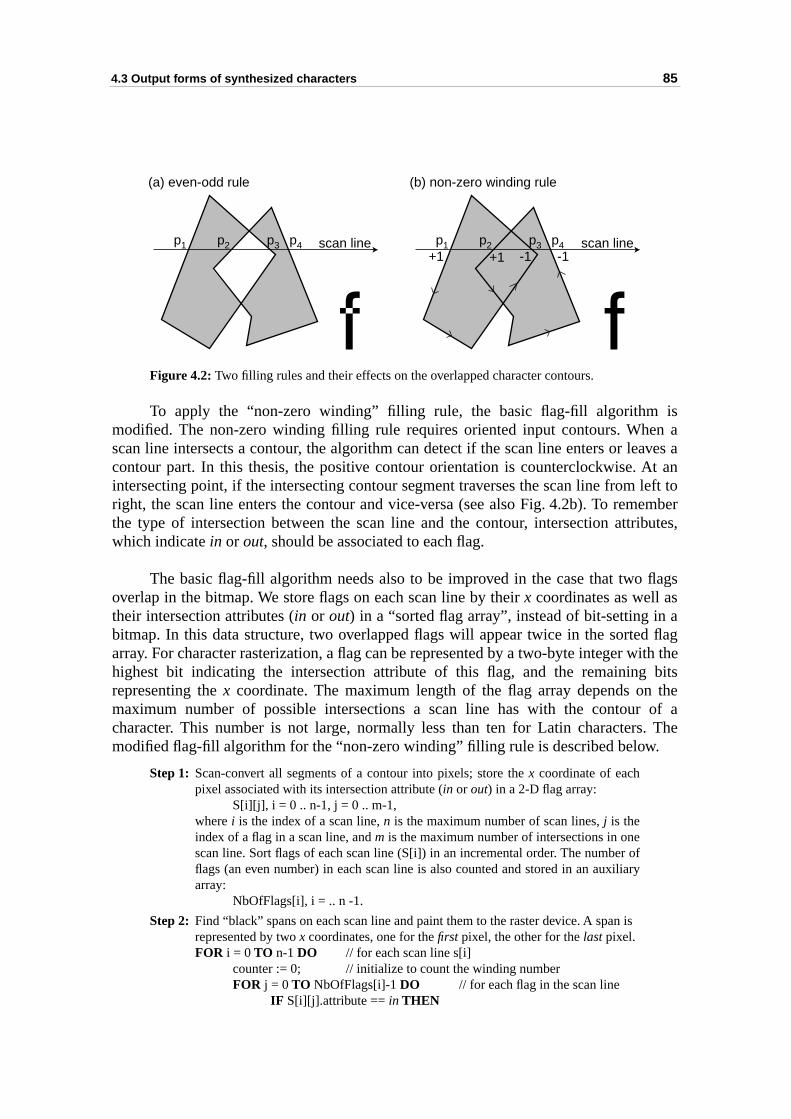
4.3 Output forms of synthesized characters 85
isen aaves at an
left toember
ibutes,
flags
ad flag
ith the bits the of a. The
Figure 4.2: Two filling rules and their effects on the overlapped character contours.
To apply the “non-zero winding” filling rule, the basic flag-fill algorithm modified. The non-zero winding filling rule requires oriented input contours. Whscan line intersects a contour, the algorithm can detect if the scan line enters or lecontour part. In this thesis, the positive contour orientation is counterclockwise. Aintersecting point, if the intersecting contour segment traverses the scan line from right, the scan line enters the contour and vice-versa (see also Fig. 4.2b). To remthe type of intersection between the scan line and the contour, intersection attrwhich indicate in or out, should be associated to each flag.
The basic flag-fill algorithm needs also to be improved in the case that twooverlap in the bitmap. We store flags on each scan line by their x coordinates as well astheir intersection attributes (in or out) in a “sorted flag array”, instead of bit-setting inbitmap. In this data structure, two overlapped flags will appear twice in the sortearray. For character rasterization, a flag can be represented by a two-byte integer whighest bit indicating the intersection attribute of this flag, and the remainingrepresenting the x coordinate. The maximum length of the flag array depends onmaximum number of possible intersections a scan line has with the contourcharacter. This number is not large, normally less than ten for Latin charactersmodified flag-fill algorithm for the “non-zero winding” filling rule is described below.
Step 1: Scan-convert all segments of a contour into pixels; store the x coordinate of eachpixel associated with its intersection attribute (in or out) in a 2-D flag array:
S[i][j], i = 0 .. n-1, j = 0 .. m-1,where i is the index of a scan line, n is the maximum number of scan lines, j is theindex of a flag in a scan line, and m is the maximum number of intersections in onescan line. Sort flags of each scan line (S[i]) in an incremental order. The number offlags (an even number) in each scan line is also counted and stored in an auxiliaryarray:
NbOfFlags[i], i = .. n -1.
Step 2: Find “black” spans on each scan line and paint them to the raster device. A span is represented by two x coordinates, one for the first pixel, the other for the last pixel.FOR i = 0 TO n-1 DO // for each scan line s[i]
counter := 0; // initialize to count the winding numberFOR j = 0 TO NbOfFlags[i]-1 DO // for each flag in the scan line
IF S[i][j].attribute == in THEN
p1 p2 p3 p4 scan line p1 p2 p3 p4 scan line+1 +1 -1 -1
(a) even-odd rule (b) non-zero winding rule
86 Chapter 4: Implementation of the parametrizable font synthesizing system
outlined shaperge allergedped.
n be spe- only aality
tionse finalion of twoeach
everalr, andollows
hich
sitive
counter := counter+1;IF counter == 1 THEN
first := S[i][j].x;ENDIF ;
ELSE // the attribute is outcounter := counter-1;IF counter == 0 THEN
last := S[i][j].x;paint_span (first, last, i); // in scan line i
ENDIF ;ENDIF;
ENDFOR;ENDFOR.
These filling functions are enclosed in a class named TFlagFill, which uses a tabledata structure to store flags and attributes of each scan line.
4.3.2 Outline generation of synthesized characters
When a synthesized character is to be used as an outline, for example to draw theof the character or to convert the synthesized characters from a component-basedescription into a traditional outline-based shape description, our system can meindividual component contours of the character into a character outline. The mcharacter outline may contain several contours but none of the contours is overlap
General purpose union or intersection algorithms for geometric shapes caapplied to merge components, for example [Vatti92]. We have developed our owncific shape merging package, which has been used in our font synthesizer. We giveshort overview of its working principles, since the detailed description of its functionis outside the scope of the present thesis.
Assuming contours have an orientation, our algorithm first detects all intersecbetween two contours. Then a tracing process is applied to find the boundary of thmerged shape. The principle of the tracing algorithm is simple. Suppose the directa positive contour is counterclockwise, the tracing algorithm for finding the union ofcontours will always choose the right-most branch candidate to follow at intersection between the two contours.
Since a character may incorporate one or several external and one or sinternal contours, we call the counterclockwise external contour a positive contouthe clockwise internal contour a negative contour. Then a shape is defined as f(also illustrated in Fig. 4.3).
Definition 4.1: A shape is a set of disconnected positive and negative contours, wsatisfy the following conditions: 1) A negative contour represents a hole and must reside inside a pocontour.
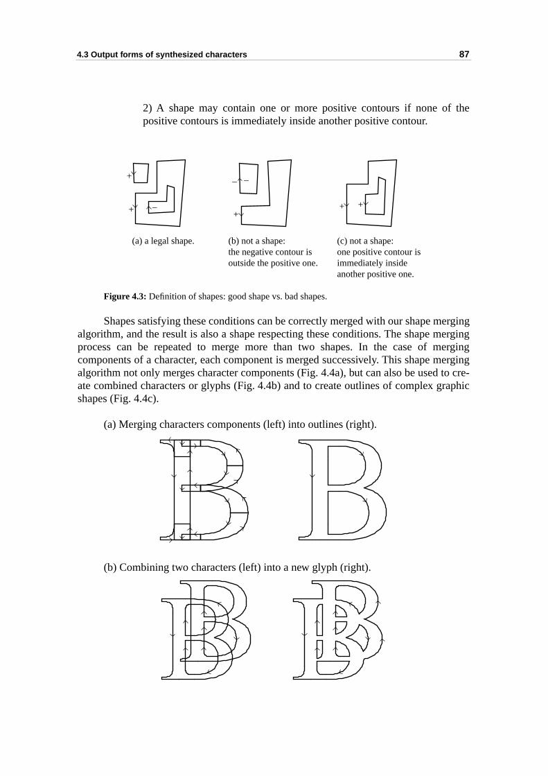
4.3 Output forms of synthesized characters 87
the
ergingergingerging
merging to cre-raphic
2) A shape may contain one or more positive contours if none ofpositive contours is immediately inside another positive contour.
Figure 4.3: Definition of shapes: good shape vs. bad shapes.
Shapes satisfying these conditions can be correctly merged with our shape malgorithm, and the result is also a shape respecting these conditions. The shape mprocess can be repeated to merge more than two shapes. In the case of mcomponents of a character, each component is merged successively. This shape algorithm not only merges character components (Fig. 4.4a), but can also be usedate combined characters or glyphs (Fig. 4.4b) and to create outlines of complex gshapes (Fig. 4.4c).
(a) Merging characters components (left) into outlines (right).
(b) Combining two characters (left) into a new glyph (right).
+
+ ++ +_
__
(a) a legal shape. (b) not a shape:the negative contour is outside the positive one.
(c) not a shape:one positive contour isimmediately insideanother positive one.
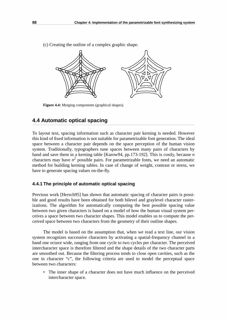
88 Chapter 4: Implementation of the parametrizable font synthesizing system
weveridealn visioners byuse atics, we
possi-raster-valuem per- the per-
visionel in aceivedr parts
h as thepace
ceived
(c) Creating the outline of a complex graphic shape.
Figure 4.4: Merging components (graphical shapes).
4.4 Automatic optical spacing
To layout text, spacing information such as character pair kerning is needed. Hothis kind of fixed information is not suitable for parametrizable font generation. The space between a character pair depends on the space perception of the humasystem. Traditionally, typographers tune spaces between many pairs of characthand and save them in a kerning table [Karow94, pp.173-192]. This is costly, becancharacters may have n2 possible pairs. For parametrizable fonts, we need an autommethod for building kerning tables. In case of change of weight, contrast or streshave to generate spacing values on-the-fly.
4.4.1 The principle of automatic optical spacing
Previous work [Hersch95] has shown that automatic spacing of character pairs is ble and good results have been obtained for both bilevel and graylevel character izations. The algorithm for automatically computing the best possible spacing between two given characters is based on a model of how the human visual systeceives a space between two character shapes. This model enables us to computeceived space between two characters from the geometry of their outline shapes.
The model is based on the assumption that, when we read a text line, our system recognizes successive characters by activating a spatial-frequency channband one octave wide, ranging from one cycle to two cycles per character. The perintercharacter space is therefore filtered and the shape details of the two characteare smoothed out. Because the filtering process tends to close open cavities, sucone in character “c”, the following criteria are used to model the perceptual sbetween two characters:
• The inner shape of a character does not have much influence on the perintercharacter space.
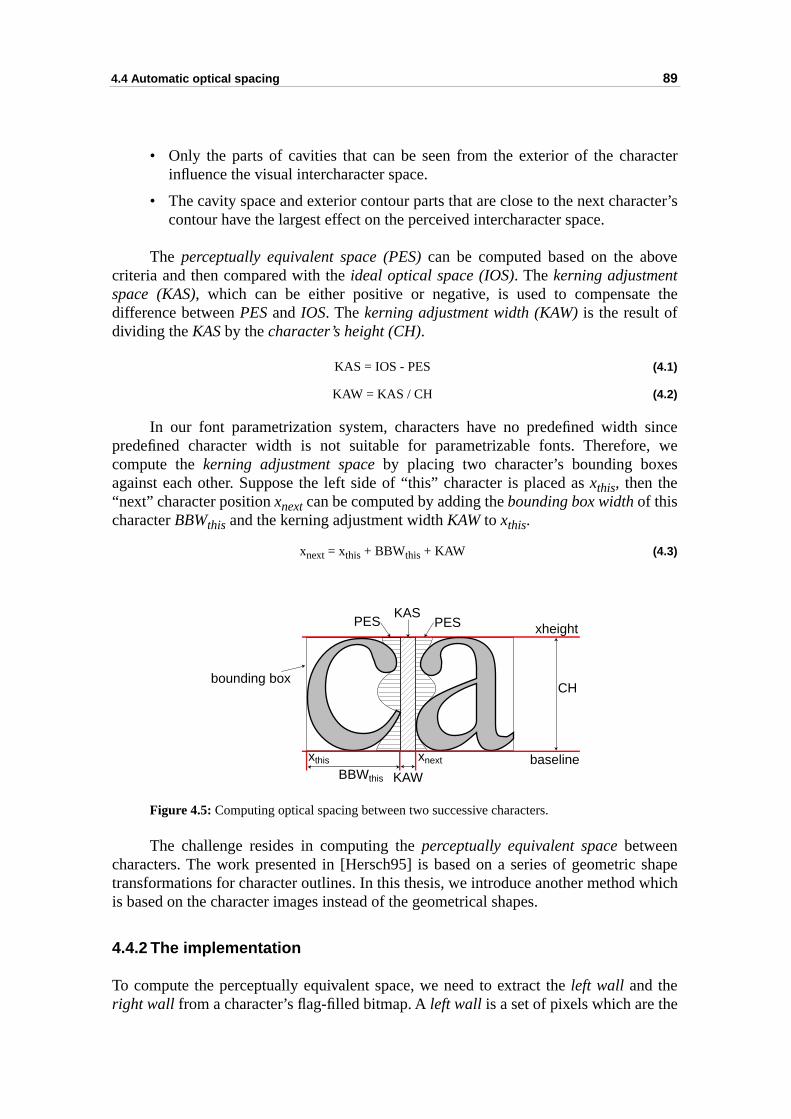
4.4 Automatic optical spacing 89
acter
acter’s
ve
the
since, wes
shapewhich
e
• Only the parts of cavities that can be seen from the exterior of the charinfluence the visual intercharacter space.
• The cavity space and exterior contour parts that are close to the next charcontour have the largest effect on the perceived intercharacter space.
The perceptually equivalent space (PES) can be computed based on the abocriteria and then compared with the ideal optical space (IOS). The kerning adjustmentspace (KAS), which can be either positive or negative, is used to compensatedifference between PES and IOS. The kerning adjustment width (KAW) is the result ofdividing the KAS by the character’s height (CH).
KAS = IOS - PES (4.1)
KAW = KAS / CH (4.2)
In our font parametrization system, characters have no predefined width predefined character width is not suitable for parametrizable fonts. Thereforecompute the kerning adjustment space by placing two character’s bounding boxeagainst each other. Suppose the left side of “this” character is placed as xthis, then the“next” character position xnext can be computed by adding the bounding box width of thischaracter BBWthis and the kerning adjustment width KAW to xthis.
xnext = xthis + BBWthis + KAW (4.3)
Figure 4.5: Computing optical spacing between two successive characters.
The challenge resides in computing the perceptually equivalent space betweencharacters. The work presented in [Hersch95] is based on a series of geometrictransformations for character outlines. In this thesis, we introduce another method is based on the character images instead of the geometrical shapes.
4.4.2 The implementation
To compute the perceptually equivalent space, we need to extract the left wall and theright wall from a character’s flag-filled bitmap. A left wall is a set of pixels which are th
xthis xnext
BBWthis KAWbaseline
xheight
bounding box
PESKAS
PES
CH
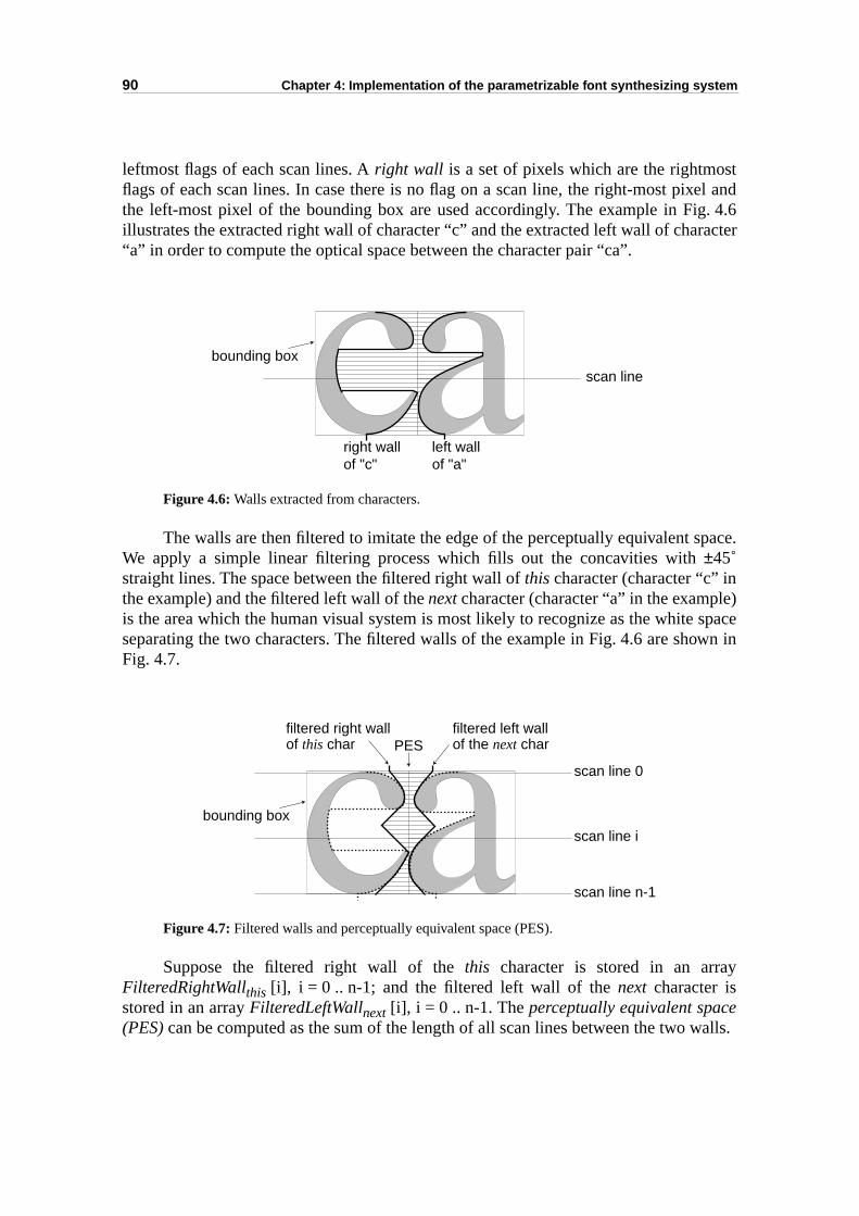
90 Chapter 4: Implementation of the parametrizable font synthesizing system
stel and. 4.6
acter
pace.
) spacewn in
y
walls.
leftmost flags of each scan lines. A right wall is a set of pixels which are the rightmoflags of each scan lines. In case there is no flag on a scan line, the right-most pixthe left-most pixel of the bounding box are used accordingly. The example in Figillustrates the extracted right wall of character “c” and the extracted left wall of char“a” in order to compute the optical space between the character pair “ca”.
Figure 4.6: Walls extracted from characters.
The walls are then filtered to imitate the edge of the perceptually equivalent sWe apply a simple linear filtering process which fills out the concavities with ±45˚straight lines. The space between the filtered right wall of this character (character “c” inthe example) and the filtered left wall of the next character (character “a” in the exampleis the area which the human visual system is most likely to recognize as the whiteseparating the two characters. The filtered walls of the example in Fig. 4.6 are shoFig. 4.7.
Figure 4.7: Filtered walls and perceptually equivalent space (PES).
Suppose the filtered right wall of the this character is stored in an arraFilteredRightWallthis [i], i = 0 .. n-1; and the filtered left wall of the next character isstored in an array FilteredLeftWallnext [i], i = 0 .. n-1. The perceptually equivalent space(PES) can be computed as the sum of the length of all scan lines between the two
bounding box
right wallof "c"
left wallof "a"
scan line
bounding boxscan line i
scan line n-1
scan line 0
filtered right wallof this char
filtered left wallof the next charPES
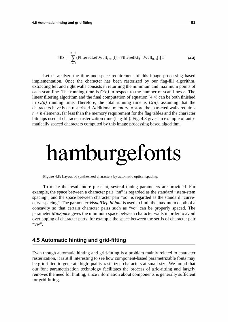
4.5 Automatic hinting and grid-fitting 91
basedrithm,ts of
ished
quiresaracter auto-
d. Form-stem“curve-a. Thevoidter pair
acters mayd that
rgelyficient
(4.4)
Let us analyze the time and space requirement of this image processing implementation. Once the character has been rasterized by our flag-fill algoextracting left and right walls consists in returning the minimum and maximum poineach scan line. The running time is O(n) in respect to the number of scan lines n. Thelinear filtering algorithm and the final computation of equation (4.4) can be both finin O(n) running time. Therefore, the total running time is O(n), assuming that thecharacters have been rasterized. Additional memory to store the extracted walls ren + n elements, far less than the memory requirement for the flag tables and the chbitmaps used at character rasterization time (flag-fill). Fig. 4.8 gives an example ofmatically spaced characters computed by this image processing based algorithm.
Figure 4.8: Layout of synthesized characters by automatic optical spacing.
To make the result more pleasant, several tuning parameters are provideexample, the space between a character pair “nn” is regarded as the standard “stespacing”, and the space between character pair “oo” is regarded as the standard curve spacing”. The parameter VisualDepthLimit is used to limit the maximum depth of concavity so that certain character pairs such as “vo” can be properly spacedparameter MinSpace gives the minimum space between character walls in order to aoverlapping of character parts, for example the space between the serifs of charac“vw”.
4.5 Automatic hinting and grid-fitting
Even though automatic hinting and grid-fitting is a problem mainly related to charrasterization, it is still interesting to see how component-based parametrizable fontbe grid-fitted to generate high-quality rasterized characters at small size. We founour font parametrization technology facilitates the process of grid-fitting and laremoves the need for hinting, since information about components is generally suffor grid-fitting.
PES FilteredLeftWallnext i[ ] FilteredRightWallthis i[ ]–( )i 0=
n 1–
∑=
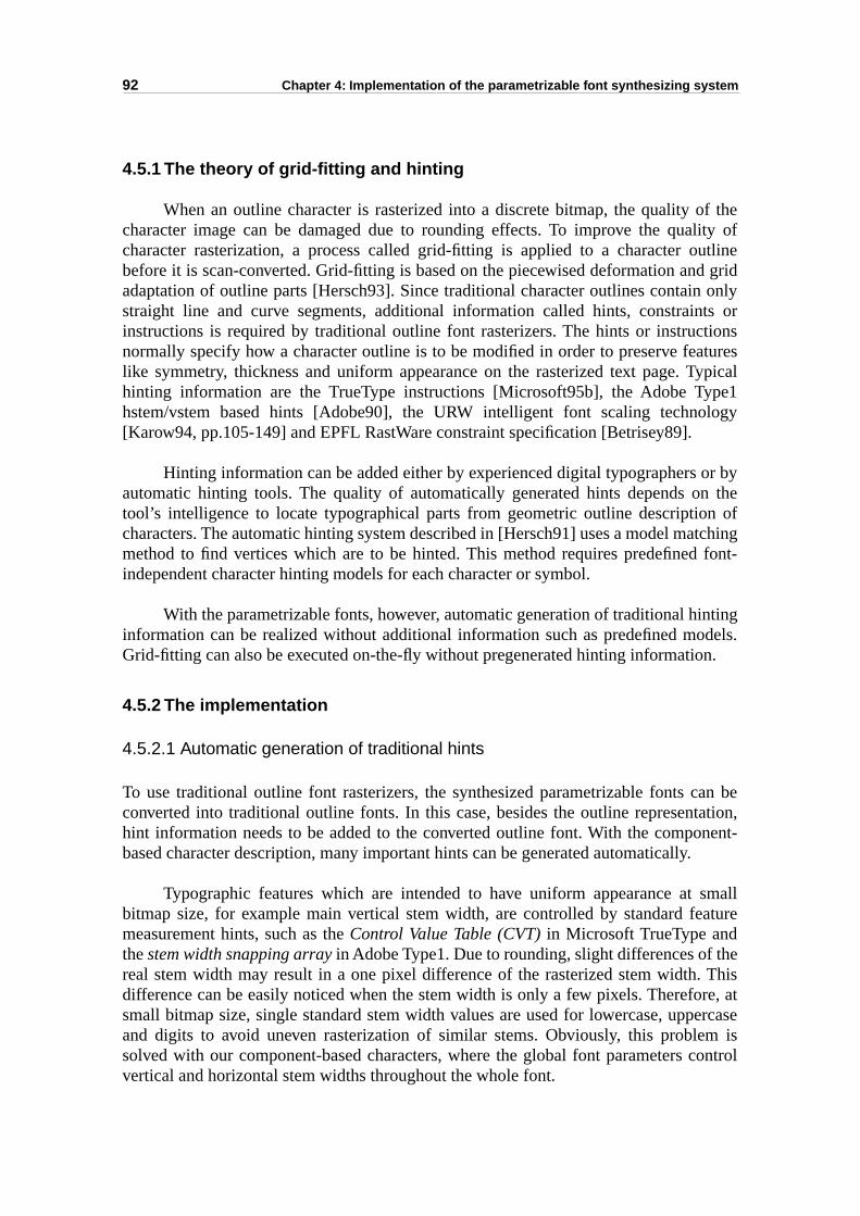
92 Chapter 4: Implementation of the parametrizable font synthesizing system
f thelity ofutlined grid onlyts ortionsturesypicalpe1logy
or byn then oftching
font-
tingdels.n.
an betation,nent-.
smallature
he Thisre, atercasem iscontrol
4.5.1 The theory of grid-fitting and hinting
When an outline character is rasterized into a discrete bitmap, the quality ocharacter image can be damaged due to rounding effects. To improve the quacharacter rasterization, a process called grid-fitting is applied to a character obefore it is scan-converted. Grid-fitting is based on the piecewised deformation anadaptation of outline parts [Hersch93]. Since traditional character outlines containstraight line and curve segments, additional information called hints, constraininstructions is required by traditional outline font rasterizers. The hints or instrucnormally specify how a character outline is to be modified in order to preserve fealike symmetry, thickness and uniform appearance on the rasterized text page. Thinting information are the TrueType instructions [Microsoft95b], the Adobe Tyhstem/vstem based hints [Adobe90], the URW intelligent font scaling techno[Karow94, pp.105-149] and EPFL RastWare constraint specification [Betrisey89].
Hinting information can be added either by experienced digital typographers automatic hinting tools. The quality of automatically generated hints depends otool’s intelligence to locate typographical parts from geometric outline descriptiocharacters. The automatic hinting system described in [Hersch91] uses a model mamethod to find vertices which are to be hinted. This method requires predefinedindependent character hinting models for each character or symbol.
With the parametrizable fonts, however, automatic generation of traditional hininformation can be realized without additional information such as predefined moGrid-fitting can also be executed on-the-fly without pregenerated hinting informatio
4.5.2 The implementation
4.5.2.1 Automatic generation of traditional hints
To use traditional outline font rasterizers, the synthesized parametrizable fonts cconverted into traditional outline fonts. In this case, besides the outline represenhint information needs to be added to the converted outline font. With the compobased character description, many important hints can be generated automatically
Typographic features which are intended to have uniform appearance at bitmap size, for example main vertical stem width, are controlled by standard femeasurement hints, such as the Control Value Table (CVT) in Microsoft TrueType andthe stem width snapping array in Adobe Type1. Due to rounding, slight differences of treal stem width may result in a one pixel difference of the rasterized stem width.difference can be easily noticed when the stem width is only a few pixels. Therefosmall bitmap size, single standard stem width values are used for lowercase, uppand digits to avoid uneven rasterization of similar stems. Obviously, this problesolved with our component-based characters, where the global font parameters vertical and horizontal stem widths throughout the whole font.
4.5 Automatic hinting and grid-fitting 93
tourontourpe 1,
ed bytheynerate
aracterintingdency quality
ttingles for
ntical oureters.ghout theonentkept
ound the x-hesisphasers of
temsstemring ah haveof the
is
ve
Hint information for individual characters specifies distances between conpoints and grid-fitting requirements. With component-based characters, these cpoints and their relationships are part of the component designs. As in Adobe Tygrid-fitting requirements may be directly derived from component information.
Some hints concern very specific character features. They are usually addexperiments [Stamm98]. However, since printing resolutions are increasing, become less and less important. Therefore, automatic hinting methods should geonly regular and important hints.
4.5.2.2 Grid-fitting component-based characters without hints
When the synthesized characters are rasterized by our component based chrasterizer (section 4.3.1), grid-fitting can be executed without any pregenerated hinformation. The component representation of typographical parts and the depenbetween components already comprise the necessary information to ensure goodgrid-fitting.
Our experimental grid-fitting of parametrizable characters uses basic grid-firules which have been proved to be the most important ones. These grid-fitting rubilevel characters include:
• Consistent character features. It is a typographer’s experience that all idecharacter parts should have an identical look. Character features inparametrizable font, such as stem width and serif height, are global paramThis means that character features are automatically kept consistent throuthe whole font. Grid-fitting requires for phase control the displacement ofcontour of a stem. If the displacement is done based on a whole compinstead of pieces of segments, the width of the stem is automatically consistent.
• Phase control of reference lines. To generate horizontally symmetric rletters such as “o”, we normally center the area between the base line andheight line on the grid. In our component-based parametrizable font syntsystem, reference line positions are global parameters. Therefore, this control of reference lines can be done by controlling the global parametethe scaled reference line positions.
• Centering of vertical and horizontal stems. Experiences show that vertical sand horizontal stems have the most impact on the human vision syespecially when a character is rasterized at a small bitmap size. Centestem at the center of a grid not only ensures that stems with the same widtthe same rasterized stem width, but also helps to maintain the symmetry stem’s serifs after rasterization. Main vertical stems in our componentdependency graph (section 3.2.1.2) are always at the second level whichdirectly controlled by the main component width of the character. To grid-fit astem, the main component width is slightly modified to ensure that successistems are centred on the grid.
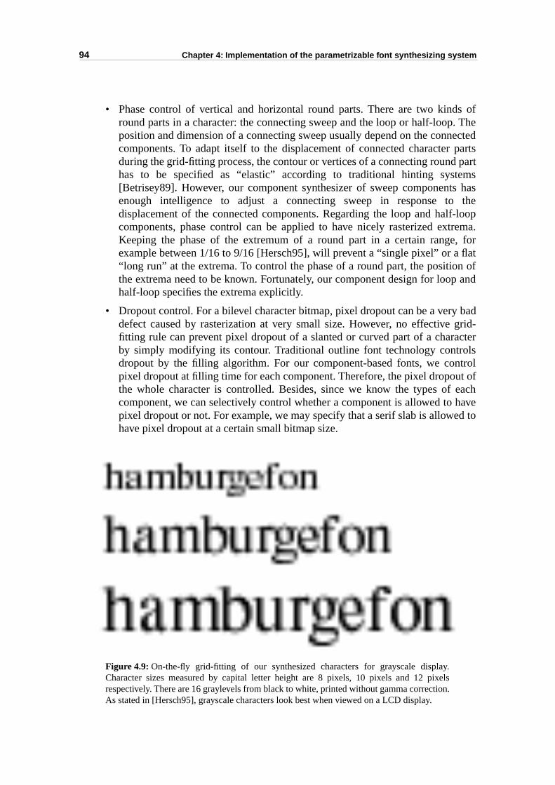
94 Chapter 4: Implementation of the parametrizable font synthesizing system
s of. Theected parts partemss has thef-looprema., for
flatn of
p and
badgrid-acterlstrolt ofeach
haved to
• Phase control of vertical and horizontal round parts. There are two kindround parts in a character: the connecting sweep and the loop or half-loopposition and dimension of a connecting sweep usually depend on the conncomponents. To adapt itself to the displacement of connected characterduring the grid-fitting process, the contour or vertices of a connecting roundhas to be specified as “elastic” according to traditional hinting syst[Betrisey89]. However, our component synthesizer of sweep componentenough intelligence to adjust a connecting sweep in response todisplacement of the connected components. Regarding the loop and halcomponents, phase control can be applied to have nicely rasterized extKeeping the phase of the extremum of a round part in a certain rangeexample between 1/16 to 9/16 [Hersch95], will prevent a “single pixel” or a“long run” at the extrema. To control the phase of a round part, the positiothe extrema need to be known. Fortunately, our component design for loohalf-loop specifies the extrema explicitly.
• Dropout control. For a bilevel character bitmap, pixel dropout can be a verydefect caused by rasterization at very small size. However, no effective fitting rule can prevent pixel dropout of a slanted or curved part of a charby simply modifying its contour. Traditional outline font technology controdropout by the filling algorithm. For our component-based fonts, we conpixel dropout at filling time for each component. Therefore, the pixel dropouthe whole character is controlled. Besides, since we know the types of component, we can selectively control whether a component is allowed topixel dropout or not. For example, we may specify that a serif slab is allowehave pixel dropout at a certain small bitmap size.
Figure 4.9: On-the-fly grid-fitting of our synthesized characters for grayscale display.Character sizes measured by capital letter height are 8 pixels, 10 pixels and 12 pixelsrespectively. There are 16 graylevels from black to white, printed without gamma correction.As stated in [Hersch95], grayscale characters look best when viewed on a LCD display.
4.6 Evaluation 95
ly the. Someceptualverti-as pos-n these pre-e base
rs andimentalodonins-seriff locala mean
lexitytively,ean of
lutionponentstems,cture toition,tc.) by
aracter he mean
Grid-fitting rules for generating good quality grayscale characters are basicalsame as the rules for bilevel characters except that dropout control is not neededmodification are however necessary to enhance the contrast and the overall perweight [Hersch95]. Instead of centering vertical stems, we align the left edge of a cal stem to the border of a pixel so that the left side of the stem appears as “black” sible. Fig. 4.9 describes the results of our on-the-fly grid-fitting method applied osynthesized characters for grayscale display. The grid-fitting methods used in theliminary experiments include centering the band area between the x-height and thlines and left aligning vertical stems to pixel boundary.
4.6 Evaluation
Component based font descriptions require global parameters, group parametelocal parameters. Tab. 4.3 shows how many parameters are needed for our experversions of parametrizable lower-case Times, Bodoni and Helvetica characters. Brequires less parameters, since all its serifs are slab serifs (zero serif depth). Safont Helvetica further reduces the number of required parameters. The number oparameters varies from character to character and from typeface to typeface, thus value is used for statistics.
A 26 lower-case character component-based parametrizable font of the compof Times requires approximately 540 parameters, i.e. 1080 bytes. ComparaTrueType requires approximately 1500 bytes for the global parameters and a m154 bytes per character for storing the outlines of lower-case characters1. The grid-fittinginstructions needed by TrueType for character generation at medium and low resorequire an additional mean amount of 385 bytes per character. In contrast, combased character descriptions already include all information about their structure (bars, arches, serifs). From our experiment of on-the-fly grid-fitting, we can conjethat the additional grid-fitting information [Adobe90][Hersch91][Karow94] requiredrasterize characters at medium and low resolution is negligibly small. In addcomponent-based fonts enable generating derived fonts (condensed, semi-bold, e
1. Composite characters such as accentuated characters are described by pointing to the basic chshape and to the accent description. Therefore, only basic characters are considered when giving tstorage cost of single character descriptions.
Table 4.3: Nb of parameters and size of font comprising lower-case characters “a” to “z”
Times Bodoni Helvetica
nb of global parameters 110 98 63
nb of group parameters 31 31 31
mean number of local parame-ters per character
15.3 16.0 14.0
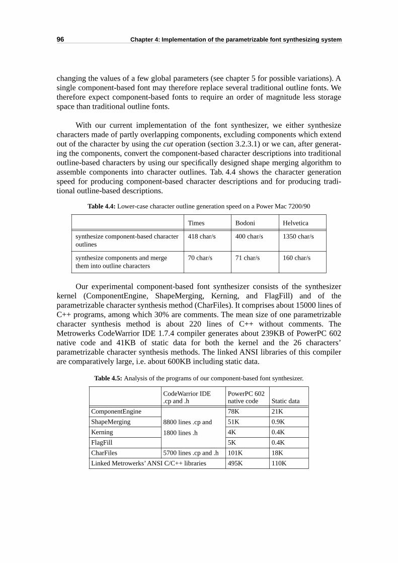
96 Chapter 4: Implementation of the parametrizable font synthesizing system
ns). Ats. Wetorage
sizextend
rat-itional
thm toeration tradi-
esizerthe
lines ofrizable The 602cters’piler
changing the values of a few global parameters (see chapter 5 for possible variatiosingle component-based font may therefore replace several traditional outline fontherefore expect component-based fonts to require an order of magnitude less sspace than traditional outline fonts.
With our current implementation of the font synthesizer, we either synthecharacters made of partly overlapping components, excluding components which eout of the character by using the cut operation (section 3.2.3.1) or we can, after geneing the components, convert the component-based character descriptions into tradoutline-based characters by using our specifically designed shape merging algoriassemble components into character outlines. Tab. 4.4 shows the character genspeed for producing component-based character descriptions and for producingtional outline-based descriptions.
Our experimental component-based font synthesizer consists of the synthkernel (ComponentEngine, ShapeMerging, Kerning, and FlagFill) and of parametrizable character synthesis method (CharFiles). It comprises about 15000 C++ programs, among which 30% are comments. The mean size of one parametcharacter synthesis method is about 220 lines of C++ without comments.Metrowerks CodeWarrior IDE 1.7.4 compiler generates about 239KB of PowerPCnative code and 41KB of static data for both the kernel and the 26 charaparametrizable character synthesis methods. The linked ANSI libraries of this comare comparatively large, i.e. about 600KB including static data.
Table 4.5: Analysis of the programs of our component-based font synthesizer.
Table 4.4: Lower-case character outline generation speed on a Power Mac 7200/90
Times Bodoni Helvetica
synthesize component-based character outlines
418 char/s 400 char/s 1350 char/s
synthesize components and merge them into outline characters
70 char/s 71 char/s 160 char/s
CodeWarrior IDE.cp and .h
PowerPC 602 native code Static data
ComponentEngine
8800 lines .cp and
1800 lines .h
78K 21K
ShapeMerging 51K 0.9K
Kerning 4K 0.4K
FlagFill 5K 0.4K
CharFiles 5700 lines .cp and .h 101K 18K
Linked Metrowerks’ ANSI C/C++ libraries 495K 110K
4.7 Summary 97
le fontble formingetrizable
er toscan-s beenditional.
r the that,study.racterssed
4.7 Summary
This chapter presented our implementation of the component-based parametrizabsynthesizing system. Since our component-based font synthesis system is suitaobject-oriented programming, the programs are written in the C++ programlanguage. The comprehensive base class makes adding a new design of a paramcharacter synthesis method as easy as creating a new derived class.
A simple grammar for writing the parameter files has been developed in ordcarry out typographic experiments. To rasterize synthesized characters, a conversion algorithm adapted for component-based character representation hapresented. The component-based representation can also be converted into traoutline-based representation using a specifically designed shape merging algorithm
Automatic optical spacing and automatic hinting are two challenging topics fotraditional outline font technology, yet have not been solved perfectly. We foundwith our component-base font parametrization method, they are both worth a new The preliminary results are encouraging. The component-based description of chais well suited for doing grid-fitting on-the-fly, using our specific component-bacharacter rasterizer.

98 Chapter 4: Implementation of the parametrizable font synthesizing system
5.1 A visual environment 99
d fonttions,eingrtiallyphy
e abasedents.
and toisualipheral
global
an belobal
usedet bar,
able in an
o open th just
CHAPTER 5
Experiments and applications
Besides the high storage compression rate (section 4.6), our component-baseparametrization method is also suitable for applying typographical typeface variawhich are often beyond the capabilities of the traditional outline font technology. Bable to carry out typeface variations has been an important goal (yet only pareached) of several previous research projects in digital typogra[Knuth86a][Shamir98][Zalik95] [Schneider98]. In this chapter, we first introducvisual font design and modification environment based on the component-parametrizable font synthesizer. Then, we will present a few typographical experim
5.1 A visual environment
To test the prototype of our component-based parametrizable font synthesizer demonstrate the flexibility and functionality of our font parametrization method, a venvironment for parameter editing and modification has been developed in the PerSystems Laboratory of the EPFL. This environment, named FlexFont Editor, integratesfunctions such as character visualization, parameter file saving and loading, parameter visual modification, and specimen printing using a multiple documentinterface (MDI)1 Windows application.
The term “visual” concerns two aspects. First, any parameter modification cseen immediately in the character display window. Second, the modifications of gparameters are done with slide bars and iconed buttons.
5.1.1 Character visualization
The overall appearance of the environment is shown in Fig. 5.1. Some frequentlytools are displayed in tool bars. There are four different tool bars: the character sthe file bar, the parameter bar and the preview bar.
The character set tool bar displays the character set in the opened parametrizfont. By clicking on a character in this tool bar, the selected character is displayed
1. A terminology of Microsoft Windows describing the application’s architecture. A multiple document interface(MDI) differs from a single document interface (SDI) in that the multiple document interface enables a user tmultiple documents each with its own windows, while the single document interface allows a user to work wione document at a time.
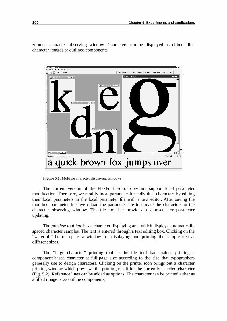
100 Chapter 5: Experiments and applications
filled
eteriting thein theeter
ally on thet at
aaphersractercterither as
zoomed character observing window. Characters can be displayed as eithercharacter images or outlined components.
Figure 5.1: Multiple character displaying windows
The current version of the FlexFont Editor does not support local parammodification. Therefore, we modify local parameter for individual characters by edtheir local parameters in the local parameter file with a text editor. After savingmodified parameter file, we reload the parameter file to update the characters character observing window. The file tool bar provides a short-cut for paramupdating.
The preview tool bar has a character displaying area which displays automaticspaced character samples. The text is entered through a text editing box. Clicking“waterfall” button opens a window for displaying and printing the sample texdifferent sizes.
The “large character” printing tool in the file tool bar enables printingcomponent-based character at full-page size according to the size that typogrgenerally use to design characters. Clicking on the printer icon brings out a chaprinting window which previews the printing result for the currently selected chara(Fig. 5.2). Reference lines can be added as options. The character can be printed ea filled image or as outline components.
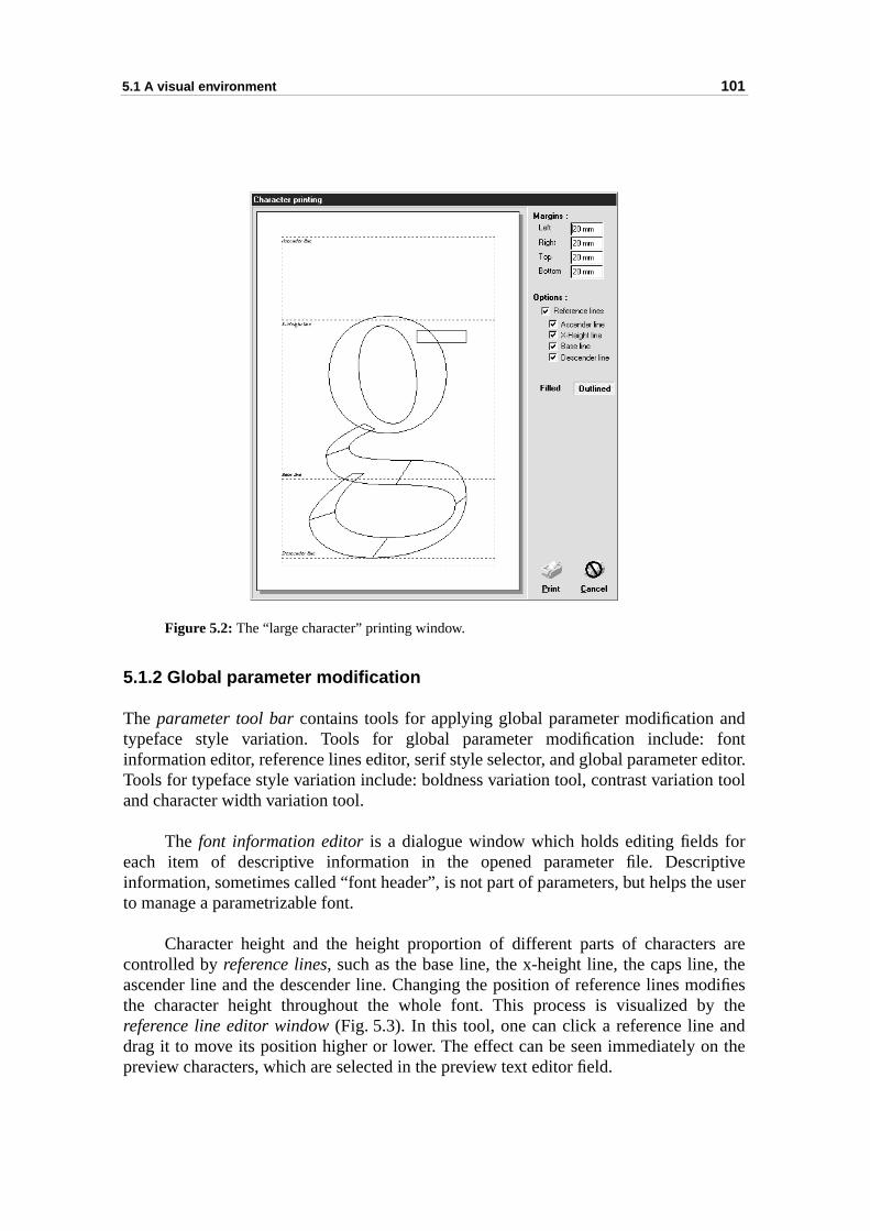
5.1 A visual environment 101
ndfonteditor. tool
rptivee user
s are, theodifiesy thendn the
Figure 5.2: The “large character” printing window.
5.1.2 Global parameter modification
The parameter tool bar contains tools for applying global parameter modification atypeface style variation. Tools for global parameter modification include: information editor, reference lines editor, serif style selector, and global parameter Tools for typeface style variation include: boldness variation tool, contrast variationand character width variation tool.
The font information editor is a dialogue window which holds editing fields foeach item of descriptive information in the opened parameter file. Descriinformation, sometimes called “font header”, is not part of parameters, but helps thto manage a parametrizable font.
Character height and the height proportion of different parts of charactercontrolled by reference lines, such as the base line, the x-height line, the caps lineascender line and the descender line. Changing the position of reference lines mthe character height throughout the whole font. This process is visualized breference line editor window (Fig. 5.3). In this tool, one can click a reference line adrag it to move its position higher or lower. The effect can be seen immediately opreview characters, which are selected in the preview text editor field.
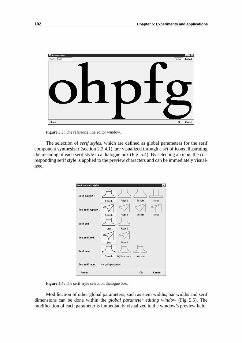
102 Chapter 5: Experiments and applications
eriftratinge cor-visual-
serif
eld.
Figure 5.3: The reference line editor window.
The selection of serif styles, which are defined as global parameters for the scomponent synthesizer (section 2.2.4.1), are visualized through a set of icons illusthe meaning of each serif style in a dialogue box (Fig. 5.4). By selecting an icon, thresponding serif style is applied to the preview characters and can be immediately ized.
Figure 5.4: The serif style selection dialogue box.
Modification of other global parameters, such as stem widths, bar widths anddimensions can be done within the global parameter editing window (Fig. 5.5). Themodification of each parameter is immediately visualized in the window’s preview fi
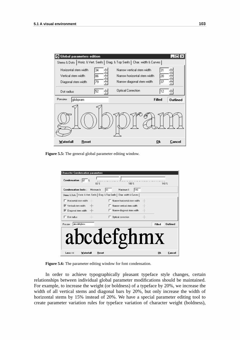
5.1 A visual environment 103
ertainined.se theth oftool toness),
Figure 5.5: The general global parameter editing window.
Figure 5.6: The parameter editing window for font condensation.
In order to achieve typographically pleasant typeface style changes, crelationships between individual global parameter modifications should be maintaFor example, to increase the weight (or boldness) of a typeface by 20%, we increawidth of all vertical stems and diagonal bars by 20%, but only increase the widhorizontal stems by 15% instead of 20%. We have a special parameter editing create parameter variation rules for typeface variation of character weight (bold
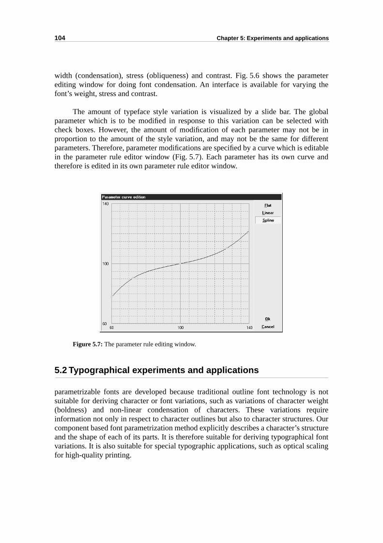
104 Chapter 5: Experiments and applications
ameter the
lobal withbe inerentditablee and
is noteight
equires. Ouructurel font
caling
width (condensation), stress (obliqueness) and contrast. Fig. 5.6 shows the parediting window for doing font condensation. An interface is available for varyingfont’s weight, stress and contrast.
The amount of typeface style variation is visualized by a slide bar. The gparameter which is to be modified in response to this variation can be selectedcheck boxes. However, the amount of modification of each parameter may not proportion to the amount of the style variation, and may not be the same for diffparameters. Therefore, parameter modifications are specified by a curve which is ein the parameter rule editor window (Fig. 5.7). Each parameter has its own curvtherefore is edited in its own parameter rule editor window.
Figure 5.7: The parameter rule editing window.
5.2 Typographical experiments and applications
parametrizable fonts are developed because traditional outline font technology suitable for deriving character or font variations, such as variations of character w(boldness) and non-linear condensation of characters. These variations rinformation not only in respect to character outlines but also to character structurecomponent based font parametrization method explicitly describes a character’s strand the shape of each of its parts. It is therefore suitable for deriving typographicavariations. It is also suitable for special typographic applications, such as optical sfor high-quality printing.
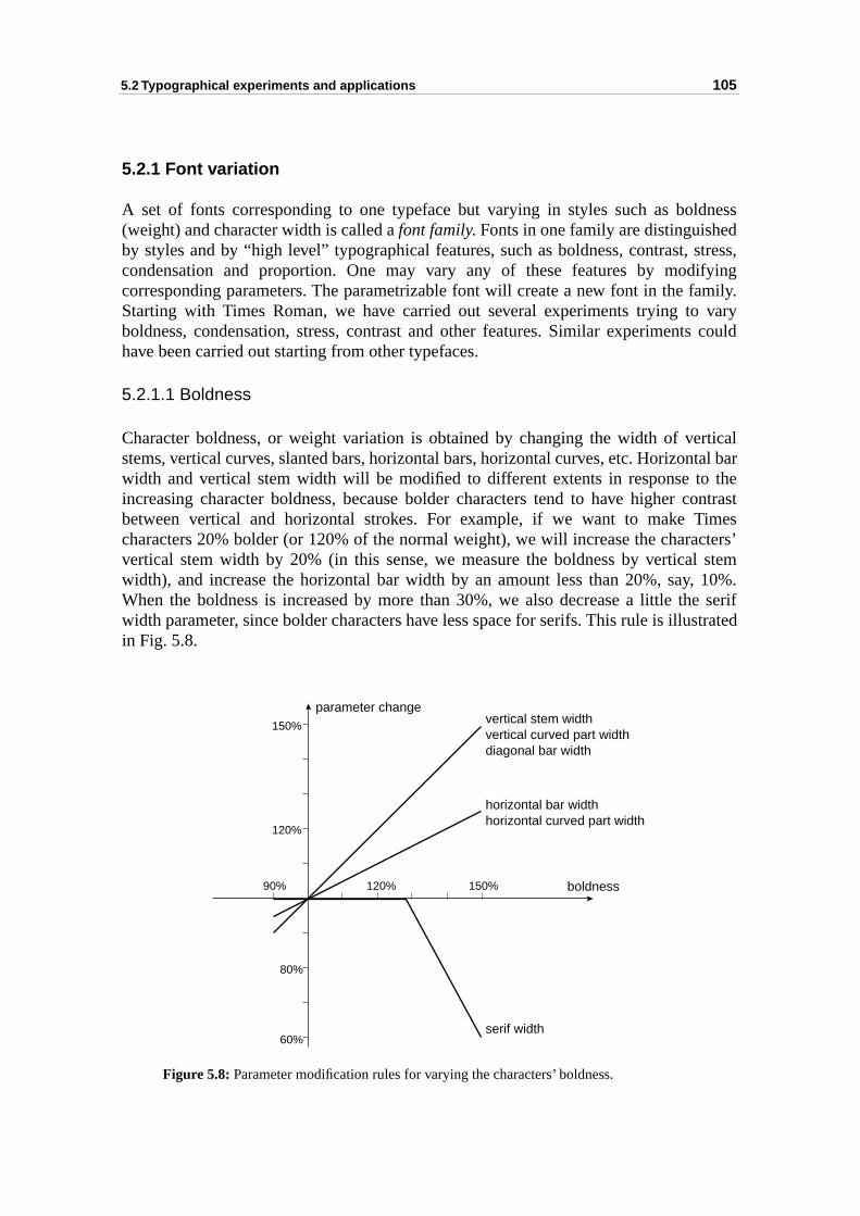
5.2 Typographical experiments and applications 105
dnessdstress,ifyingamily. varys could
rticaltal bar thecontrastimescters’l stem 10%.e serifstrated
5.2.1 Font variation
A set of fonts corresponding to one typeface but varying in styles such as bol(weight) and character width is called a font family. Fonts in one family are distinguisheby styles and by “high level” typographical features, such as boldness, contrast, condensation and proportion. One may vary any of these features by modcorresponding parameters. The parametrizable font will create a new font in the fStarting with Times Roman, we have carried out several experiments trying toboldness, condensation, stress, contrast and other features. Similar experimenthave been carried out starting from other typefaces.
5.2.1.1 Boldness
Character boldness, or weight variation is obtained by changing the width of vestems, vertical curves, slanted bars, horizontal bars, horizontal curves, etc. Horizonwidth and vertical stem width will be modified to different extents in response toincreasing character boldness, because bolder characters tend to have higher between vertical and horizontal strokes. For example, if we want to make Tcharacters 20% bolder (or 120% of the normal weight), we will increase the charavertical stem width by 20% (in this sense, we measure the boldness by verticawidth), and increase the horizontal bar width by an amount less than 20%, say,When the boldness is increased by more than 30%, we also decrease a little thwidth parameter, since bolder characters have less space for serifs. This rule is illuin Fig. 5.8.
Figure 5.8: Parameter modification rules for varying the characters’ boldness.
150%120%90%
120%
80%
60%
150%vertical stem widthvertical curved part widthdiagonal bar width
horizontal bar widthhorizontal curved part width
serif width
boldness
parameter change
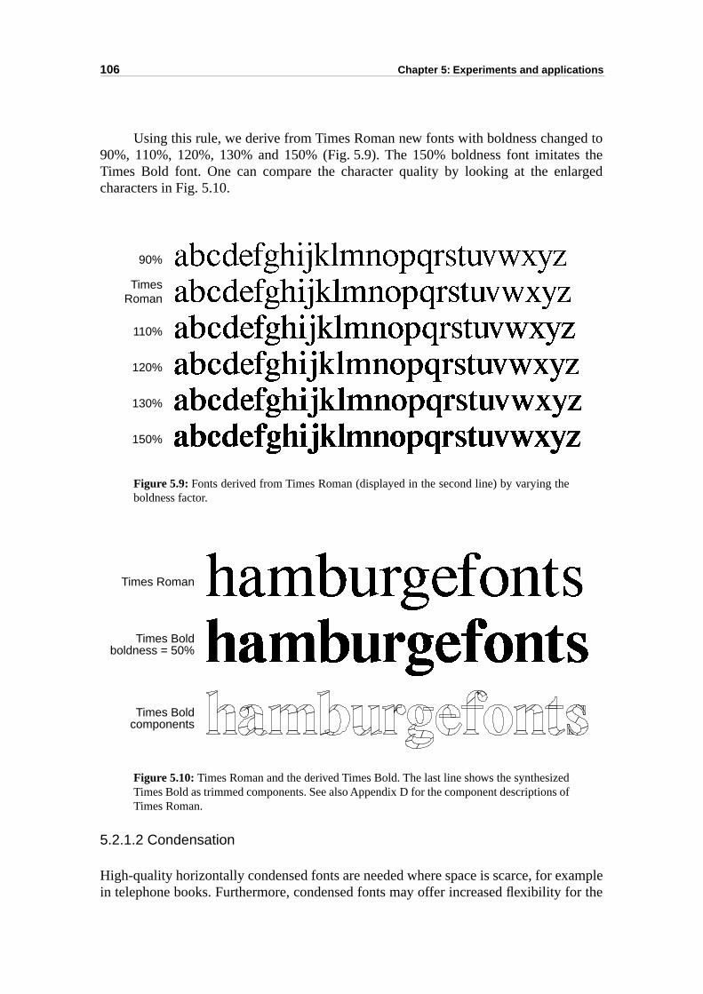
106 Chapter 5: Experiments and applications
ed tos the
arged
ampler the
Using this rule, we derive from Times Roman new fonts with boldness chang90%, 110%, 120%, 130% and 150% (Fig. 5.9). The 150% boldness font imitateTimes Bold font. One can compare the character quality by looking at the enlcharacters in Fig. 5.10.
Figure 5.9: Fonts derived from Times Roman (displayed in the second line) by varying theboldness factor.
Figure 5.10: Times Roman and the derived Times Bold. The last line shows the synthesizedTimes Bold as trimmed components. See also Appendix D for the component descriptions ofTimes Roman.
5.2.1.2 Condensation
High-quality horizontally condensed fonts are needed where space is scarce, for exin telephone books. Furthermore, condensed fonts may offer increased flexibility fo
90%
TimesRoman
110%
120%
130%
150%
Times Roman
Times Boldboldness = 50%
Times Boldcomponents
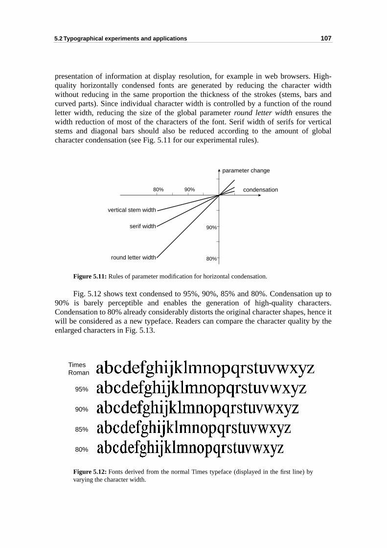
5.2 Typographical experiments and applications 107
igh-widthrs andound
ticalglobal
up tocters.ence it by the
presentation of information at display resolution, for example in web browsers. Hquality horizontally condensed fonts are generated by reducing the character without reducing in the same proportion the thickness of the strokes (stems, bacurved parts). Since individual character width is controlled by a function of the rletter width, reducing the size of the global parameter round letter width ensures thewidth reduction of most of the characters of the font. Serif width of serifs for verstems and diagonal bars should also be reduced according to the amount of character condensation (see Fig. 5.11 for our experimental rules).
Figure 5.11: Rules of parameter modification for horizontal condensation.
Fig. 5.12 shows text condensed to 95%, 90%, 85% and 80%. Condensation90% is barely perceptible and enables the generation of high-quality charaCondensation to 80% already considerably distorts the original character shapes, hwill be considered as a new typeface. Readers can compare the character qualityenlarged characters in Fig. 5.13.
Figure 5.12: Fonts derived from the normal Times typeface (displayed in the first line) byvarying the character width.
90%80%
90%
80%
vertical stem width
serif width
round letter width
condensation
parameter change
TimesRoman
95%
90%
85%
80%
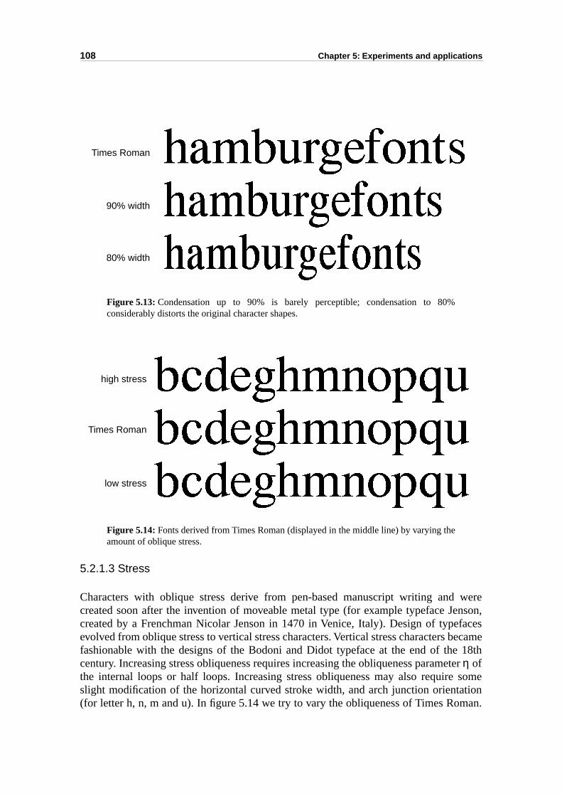
108 Chapter 5: Experiments and applications
wereenson,faces
became 18thter sometionman.
Figure 5.13: Condensation up to 90% is barely perceptible; condensation to 80%considerably distorts the original character shapes.
Figure 5.14: Fonts derived from Times Roman (displayed in the middle line) by varying theamount of oblique stress.
5.2.1.3 Stress
Characters with oblique stress derive from pen-based manuscript writing and created soon after the invention of moveable metal type (for example typeface Jcreated by a Frenchman Nicolar Jenson in 1470 in Venice, Italy). Design of typeevolved from oblique stress to vertical stress characters. Vertical stress characters fashionable with the designs of the Bodoni and Didot typeface at the end of thecentury. Increasing stress obliqueness requires increasing the obliqueness parameη ofthe internal loops or half loops. Increasing stress obliqueness may also requireslight modification of the horizontal curved stroke width, and arch junction orienta(for letter h, n, m and u). In figure 5.14 we try to vary the obliqueness of Times Ro
Times Roman
90% width
80% width
high stress
Times Roman
low stress
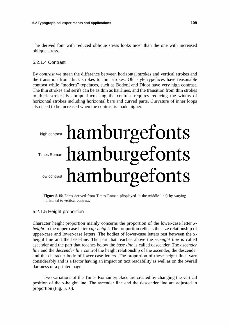
5.2 Typographical experiments and applications 109
eased
s andnabletrast.trokes
hs ofloops
ter of the x-
nders varyverall
rticalted in
The derived font with reduced oblique stress looks nicer than the one with incroblique stress.
5.2.1.4 Contrast
By contrast we mean the difference between horizontal strokes and vertical strokethe transition from thick strokes to thin strokes. Old style typefaces have reasocontrast while “modern” typefaces, such as Bodoni and Didot have very high conThe thin strokes and serifs can be as thin as hairlines, and the transition from thin sto thick strokes is abrupt. Increasing the contrast requires reducing the widthorizontal strokes including horizontal bars and curved parts. Curvature of inner also need to be increased when the contrast is made higher.
Figure 5.15: Fonts derived from Times Roman (displayed in the middle line) by varyinghorizontal to vertical contrast.
5.2.1.5 Height proportion
Character height proportion mainly concerns the proportion of the lower-case letx-height to the upper-case letter cap-height. The proportion reflects the size relationship upper-case and lower-case letters. The bodies of lower-case letters rest betweenheight line and the base-line. The part that reaches above the x-height line is calledascender and the part that reaches below the base line is called descender. The ascenderline and the descender line control the height relationship of the ascender, the desceand the character body of lower-case letters. The proportion of these height lineconsiderably and is a factor having an impact on text readability as well as on the odarkness of a printed page.
Two variations of the Times Roman typeface are created by changing the veposition of the x-height line. The ascender line and the descender line are adjusproportion (Fig. 5.16).
high contrast
Times Roman
low contrast
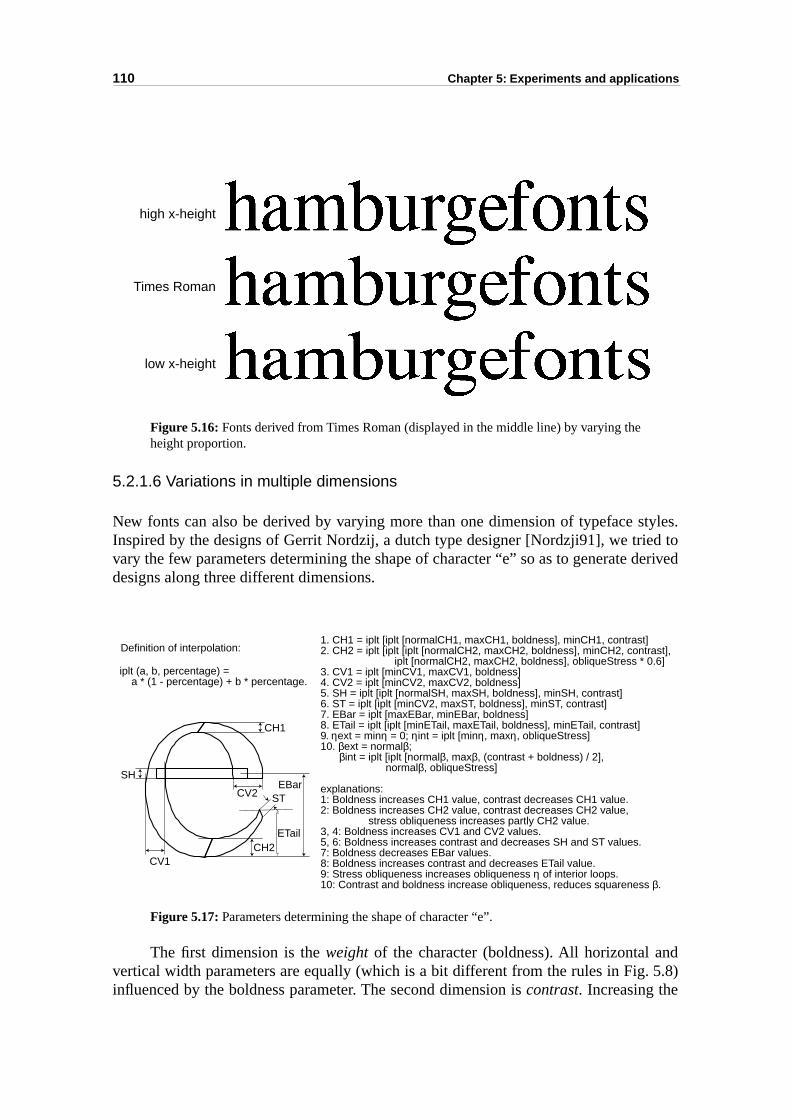
110 Chapter 5: Experiments and applications
tyles.d to
derived
d 5.8)
Figure 5.16: Fonts derived from Times Roman (displayed in the middle line) by varying theheight proportion.
5.2.1.6 Variations in multiple dimensions
New fonts can also be derived by varying more than one dimension of typeface sInspired by the designs of Gerrit Nordzij, a dutch type designer [Nordzji91], we trievary the few parameters determining the shape of character “e” so as to generate designs along three different dimensions.
Figure 5.17: Parameters determining the shape of character “e”.
The first dimension is the weight of the character (boldness). All horizontal anvertical width parameters are equally (which is a bit different from the rules in Fig.influenced by the boldness parameter. The second dimension is contrast. Increasing the
high x-height
Times Roman
low x-height
1. CH1 = iplt [iplt [normalCH1, maxCH1, boldness], minCH1, contrast]2. CH2 = iplt [iplt [iplt [normalCH2, maxCH2, boldness], minCH2, contrast], iplt [normalCH2, maxCH2, boldness], obliqueStress * 0.6]3. CV1 = iplt [minCV1, maxCV1, boldness]4. CV2 = iplt [minCV2, maxCV2, boldness]5. SH = iplt [iplt [normalSH, maxSH, boldness], minSH, contrast]6. ST = iplt [iplt [minCV2, maxST, boldness], minST, contrast]7. EBar = iplt [maxEBar, minEBar, boldness]8. ETail = iplt [iplt [minETail, maxETail, boldness], minETail, contrast]9. ηext = minη = 0; ηint = iplt [minη, maxη, obliqueStress]10. βext = normalβ; βint = iplt [iplt [normalβ, maxβ, (contrast + boldness) / 2], normalβ, obliqueStress]
explanations:1: Boldness increases CH1 value, contrast decreases CH1 value.2: Boldness increases CH2 value, contrast decreases CH2 value, stress obliqueness increases partly CH2 value.3, 4: Boldness increases CV1 and CV2 values.5, 6: Boldness increases contrast and decreases SH and ST values.7: Boldness decreases EBar values.8: Boldness increases contrast and decreases ETail value.9: Stress obliqueness increases obliqueness η of interior loops.10: Contrast and boldness increase obliqueness, reduces squareness β.
CH1
CH2
CV2
CV1
SH
ST
ETail
EBar
iplt (a, b, percentage) = a * (1 - percentage) + b * percentage.
Definition of interpolation:
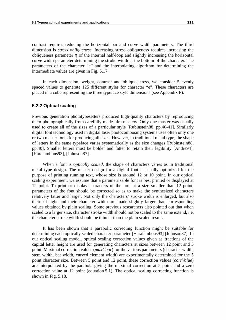
5.2 Typographical experiments and applications 111
third thetalr. The the
venlyers are).
ducinguallyilarlyly onehapetein88,94],
nalr theticalyed atoint,racters
alsondingt whenend, i.e.
for87]. Inf thet and 5th,the 5
zeron is
contrast requires reducing the horizontal bar and curve width parameters. Thedimension is stress obliqueness. Increasing stress obliqueness requires increasingobliqueness parameter η of the internal half-loop and slightly increasing the horizoncurve width parameter determining the stroke width at the bottom of the characteparameters of the character “e” and the interpolating algorithm for determiningintermediate values are given in Fig. 5.17.
In each dimension, weight, contrast and oblique stress, we consider 5 espaced values to generate 125 different styles for character “e”. These charactplaced in a cube representing the three typeface style dimensions (see Appendix F
5.2.2 Optical scaling
Previous generation phototypesetters produced high-quality characters by reprothem photographically from carefully made film masters. Only one master was usused to create all of the sizes of a particular style [Rubinstein88, pp.40-41]. Simdigital font technology used in digital laser photocomposing systems uses often onor two master fonts for producing all sizes. However, in traditional metal type, the sof letters in the same typeface varies systematically as the size changes [Rubinspp.40]. Smaller letters must be bolder and fatter to retain their legibility [André[Haralambous93], [Johnson87].
When a font is optically scaled, the shape of characters varies as in traditiometal type design. The master design for a digital font is usually optimized fopurpose of printing running text, whose size is around 12 or 10 point. In our opscaling experiment, we assume that a parametrizable font is best printed or displa12 point. To print or display characters of the font at a size smaller than 12 pparameters of the font should be corrected so as to make the synthesized charelatively fatter and larger. Not only the characters’ stroke width is enlarged, buttheir x-height and their character width are made slightly larger than correspovalues obtained by plain scaling. Some previous researchers also pointed out thascaled to a larger size, character stroke width should not be scaled to the same extthe character stroke width should be thinner than the plain scaled result.
It has been shown that a parabolic correcting function might be suitabledetermining each optically scaled character parameter [Haralambous93] [Johnsonour optical scaling model, optical scaling correction values given as fractions ocapital letter height are used for generating characters at sizes between 12 poinpoint. Maximal correction values (maxCoor) for the various parameters (character widstem width, bar width, curved element width) are experimentally determined for point character size. Between 5 point and 12 point, these correction values (corrValue)are interpolated by the parabola giving the maximal correction at 5 point and acorrection value at 12 point (equation 5.1). The optical scaling correcting functioshown in Fig. 5.18.
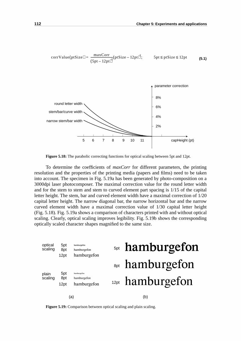
112 Chapter 5: Experiments and applications
takenn on a
widthcapitalf 1/20arroweightpticalding
(5.1)
Figure 5.18: The parabolic correcting functions for optical scaling between 5pt and 12pt.
To determine the coefficients of maxCorr for different parameters, the printingresolution and the properties of the printing media (papers and films) need to beinto account. The specimen in Fig. 5.19a has been generated by photo-compositio3000dpi laser photocomposer. The maximal correction value for the round letter and for the stem to stem and stem to curved element part spacing is 1/15 of the letter height. The stem, bar and curved element width have a maximal correction ocapital letter height. The narrow diagonal bar, the narrow horizontal bar and the ncurved element width have a maximal correction value of 1/30 capital letter h(Fig. 5.18). Fig. 5.19a shows a comparison of characters printed with and without oscaling. Clearly, optical scaling improves legibility. Fig. 5.19b shows the corresponoptically scaled character shapes magnified to the same size.
Figure 5.19: Comparison between optical scaling and plain scaling.
corrValue ptSize( ) maxCorr
5pt 12pt–( )2-------------------------------- ptSize 12pt–( )2 5pt ptSize 12pt≤ ≤;=
parameter correction
capHeight (pt)10 115 6 7 8 9
2%
4%
6%
8%
round letter width
stem/bar/curve width
narrow stem/bar width
opticalscaling
plainscaling
5pt8pt
12pt
5pt8pt
12pt
5pt
8pt
12pt
(a) (b)
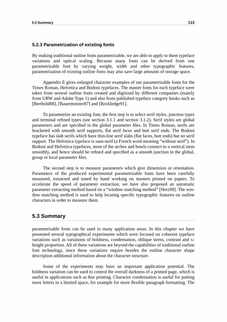
5.3 Summary 113
eface oneres,ace.
or thee wereainlych as
types globalrifs areodonio seriff”). Inl stemglobal,
tation.refullyrs. Totomatic win-utline
e havepeface and x-tlineshape
Thehich isutting. The
5.2.3 Parametrization of existing fonts
By making traditional outline fonts parametrizable, we are able to apply to them typvariations and optical scaling. Because many fonts can be derived fromparametrizable font by varying weight, width and other typographic featuparametrization of existing outline fonts may also save large amounts of storage sp
Appendix E gives enlarged character examples of our parametrizable fonts fTimes Roman, Helvetica and Bodoni typefaces. The master fonts for each typefactaken from several outline fonts created and digitized by different companies (mfrom URW and Adobe Type 1) and also from published typeface category books su[Berthold88], [Bauermeister87] and [Rockledge91].
To parametrize an existing font, the first step is to select serif styles, junction and terminal refined types (see section 3.1.1 and section 3.1.2). Serif styles areparameters and are specified in the global parameter files. In Times Roman, sebracketed with smooth serif supports, flat serif faces and butt serif ends. The Btypeface has slab serifs which have thin-line serif slabs (flat faces, butt ends) but nsupport. The Helvetica typeface is sans-serif (a French word meaning “without seriBodoni and Helvetica typefaces, most of the arches and bowls connect to a verticasmoothly, and hence should be refined and specified as a smooth junction in the group or local parameter files.
The second step is to measure parameters which give dimension or orienParameters of the produced experimental parametrizable fonts have been cameasured, extracted and tuned by hand working on masters printed on papeaccelerate the speed of parameter extraction, we have also proposed an auparameter extracting method based on a “window matching method” [Herz98]. Thedow matching method is used to help locating specific typographic features on ocharacters in order to measure them.
5.3 Summary
parametrizable fonts can be used in many application areas. In this chapter wpresented several typographical experiments which were focused on coherent tyvariations such as variations of boldness, condensation, oblique stress, contrastheight proportion. All of these variations are beyond the capabilities of traditional oufont technology, since these variations require besides the outline character description additional information about the character structure.
Some of the experiments may have an important application potential.boldness variation can be used to control the overall darkness of a printed page, wuseful in applications such as fine printing. Character condensation is useful for pmore letters in a limited space, for example for more flexible paragraph formatting

114 Chapter 5: Experiments and applications
metal
optical scaling experiment was able to produce designs similar to the traditional type where character shapes are adjusted at different sizes.
115
-based1, weshapehapteraracterspter 4,nted.
ies of
hapee; they studysignedate forraphicscribe by theurvedponent
eated weres sucheter file definet styleacrosslobal
izableied toeateased
CHAPTER 6
Conclusion and future work
This dissertation presents the study and the development of a componentparametrizable character synthesis method. Following the introduction in chapter describe in detail in chapter 2 our design of components, i.e. parametrizable primitives used for synthesizing structure elements of typographic characters. In c3, we discuss the parametrizable character synthesis system which describes chby predefined parametrizable components and shape trimming operations. In chaour implementation of a C++ prototype for this font parametrization system is preseIn chapter 5, we carry out typographical experiments demonstrating the capabilitour component based parametrizable font synthesizing system.
Let us summarize the main contributions and achievements of this thesis.
Our attempt to reproduce existing text typefaces by parametrizable sprimitives has been successful. Curved parts of characters are difficult to synthesizare of primary importance to obtain high-quality characters. Based on a systematicof the curves suitable for parametrization of round parts of characters, we have dethe loop, half-loop and sweep components. These components were adequsynthesizing the shapes of round parts and of curved connections in typogcharacters. Terminals of strokes differ across different text typefaces. We determinals of straight strokes (such as vertical stems, horizontal and diagonal bars)serif component which enables us to synthesize most serif types. Terminals of cstrokes are synthesized by the combination of the dot component, the sweep comand automatically generated smoothing shapes.
Using our parametrizable font synthesizing system, we have successfully crhigh-quality derived fonts. Relationship between character structure elementsmaintained. We ensure that no components fall apart when we vary font propertieas boldness, condensation, contrast and oblique stress. The hierarchical paramorganization and the PostScript-like parameter expressions provide the means toparameter modifying rules for each parameter in order to achieve coherent fonvariations. We are also able to make coherent typographical feature modifications a whole font or across a set of characters by modifying respectively the gparameters or the group parameters.
Typographical experiments demonstrate the application potential of parametrcomponent-based fonts. Font style variations and optical scaling can be applimprove text printing quality. With our font parametrization system, one can crpersonalized font by coherently modifying some parameters. Component-b
116 Chapter 6: Conclusion and future work
a fewmeters
-basedtronic
in the
searchy be
onentsattemptapherstionsf this
andaracter
parametrized fonts require much less storage space than outline fonts. With parameter changes, derived fonts can be instantly created. A restricted set of parais sufficient to generate all characters needed within a document. Componentparametrized fonts can therefore be delivered together with documents over elecnetworks (Internet).
The research started with this thesis can be continued in the future, at leastfollowing directions:
The use of local parameters is cumbersome at this stage. In a future reproject, local parameters may be regularized and simplified. Visual tools madeveloped to help editing local parameters.
The idea of describing characters by predefined parametrizable shape compis quite suitable for stroke-based characters, for example Chinese characters. The to describing Chinese characters by “basic strokes” has been tried by some typogrand computer scientists. However, the quality of curved strokes and the juncbetween strokes remain problematic. The author believes that some results odissertation, such as the β-Bézier curve controlling method, the sweep component the smoothing operation, can be extended to help solving problems for Chinese chparametrization.
117
ont
Inc.,
izedd
e
ifyingB. B.am,
.
tline) 242-
,
References
[Adams89] D. Adams, abcdefg - A Better Constraint Driven Environment for FGeneration, Raster Imaging and Digital Typography (RIDT’89), Eds. J.André and R. D. Hersch, Cambridge University Press, 1989, 54-70.
[Adobe85] Adobe Systems Inc., PostScript Language Reference Manual, Addison-Wesley, 1985.
[Adobe90] Adobe Systems Inc., The Type 1 Format Specification, Addison-Wesley,1990.
[Adobe92] J. Seybold, Adobe’s MultiMasters Technology: Breakthrough in TypeAesthetics, Seybold Report on Desktop Publishing, Vol. 7, No. 5, 1991, 3-7, see also "Designing Multiple Master Typefaces", Adobe Systems http://www.adobe.com.
[Agfa91] Agfa Corp., Intellifont Scalable Typeface Format, 1991.
[André94] Jacques André, Irene Vatton, Dynamic Optical Scaling and Variable-SCharacters, Electronic Publishing - Origination, Dissemination anDesign, Vol. 7, No. 4, 1994, 231–250.
[Bauermeister87] Benjamin Bauermeister, A Manual of Comparative Typography (thPANOSE system), Van Nostrand Reinhold, NY, 1987.
[Bauermeister96] US Patent 5’586’241, Method and System for Creating, Specand Generating Parametric Fonts, issued Dec. 17, 1996, inventors: Bauermeister, C. D. MacQueen, M. S. DeLaurentis, P. M. HiginbothD. E. Lipkie, D. J. Munsil, R. G. Beausoleil.
[Berthold88] H.Berthold AG, Berthold Types, H. Berthold AG, Berlin, Germany, 1988
[Betrisey89] Claude Betrisey and Roger D. Hersch, Flexible Application of OuGrid Constraints, Raster Imaging and Digital Typography (RIDT’89,Eds. J. André and R. D. Hersch, Cambridge University Press, 1989,250.
[Billawala89] N. Billawala, Panadora-an Experience with Metafont, Raster Imagingand Digital Typography (RIDT’89), Eds. J. André and R. D. HerschCambridge University Press, 1989, 34-53.
118 References
hesis
raytter.,
ese
anjid
tric
,
s,
cter,8/98,
rough,n
[Coueignoux75] Ph. Coueignoux, Generation of Roman Printed Fonts, Ph.D T(adviser: Prof. Schreiber), MIT, June 1975.
[Coueignoux81] Ph. Coueignoux, Character Generation by Computer, ComputerGraphics and Image Processing, Vol. 16, 1981, 240–269.
[Cox82] Charles H. Cox III, Philippe Coueignoux, Barry Blesser and MurEden, Skeletons: A Link Between Theoretical and Physical LeDescriptions, Pattern Recognition, Vol. 15, No. 1, Pergamon Press LtdGreat Britain, 1982, 11-22.
[Dong91] Yunmei Dong & Kaide Li, A Parametric Graphics Approach to ChinFont Design, Raster Imaging and Digital Typography II (RIDT’91), Eds.R. Morris and J. André, Cambridge University Press, 1991, 156-165.
[Dürst93] Martin J. Dürst, Coordinate-Indenpendent Font Description Using Kas an Example, Electronic Publishing - Origination, Dissemination anDesign (RIDT’94), Vol. 6, No. 3, 1993, 133-143.
[Fan91] Jianping Fan, Towards Intelligent Chinese Character Design, RasterImaging and Digital Typography II (RIDT’91), Eds. R. Morris and J.André, Cambridge University Press, 1991, 166-176.
[Farin90] Gerald Farin, Curves and Surfaces for Computer Aided GeomeDesign: A Practical Guide (2nd edition), Academic Press, 1990.
[Foley90] James D. Foley et al, Computer Graphics: Principles and PracticeSecond Edition, Addison-Wesley, 1990.
[Gaskell76] P. Gaskell, A Nomenclature for the Letterforms of Roman Type, VisibleLanguage, Vol. 10, No. 1, 1976, 41–51.
[Gonczarowski93] Jakob Gonczarowski, Curve Technique for Auto-Tracing, Visual andTechnical Aspects of Type, Ed. R. D. Hersch, Cambridge Unicersity Pres1993, 126-147.
[Gonczarowski98] Jakob Gonczarowski, Producing the Skeleton of a CharaElectronic Publishing, Artistic Imaging, and Digital Typography (EP’9RIDT’98), Eds. R. D. Hersch et al., LNCS 1375, Springer-Verlag, 1966-76.
[Haralambous93] Yannis Haralambous, Parametrization of PostScript Fonts ThMETAFONT - An Alternative to Adobe Multiple Master FontsElectronic Publishing - Origination, Dissemination and Desig(RIDT’94), Vol. 6, No. 3, 1993, 145–157.
119
se,.
ng of
s,
rtler,
ting
tring
sis Nº
rsch,terl,
sics,tern,
tline
[Haralambous94] Yannis Haralambous, Typesetting Khmer, Electronic Publishing -Origination, Dissemination and Design, Vol. 7, No. 4, J. Wiley, 1994,197–215.
[Hersch88] Roger D. Hersch, Vertical Scan-Conversion for Filling PurpoProceedings CGI’88, Geneva, Ed. D. Thalmann, Springer Verlag, 1988
[Hersch91] Roger D. Hersch, Claude Bétrisey, Model-based Matching and HintiFonts, Proceedings Siggraph'91, ACM Computer graphics, Vol. 25, No.4, 1991, 71–80.
[Hersch93] Roger D. Hersch, Font Rasterization: the State of the Art, Visual andTechnical Aspects of Type, Ed. R. D. Hersch, Cambridge University Pres1993, 78-109.
[Hersch95] Roger D. Hersch, Claude Bétrisey, Justin Bur, and Andre GuPerceptually Tuned Generation of Grayscale Fonts, IEEE ComputerGraphics and Applications, Vol. 15, No. 6, November 1995, 78-89.
[Herz94a] Jacky Herz and Roger D. Hersch, Towards a Universal Auto-HinSystem for Typographic Shapes, Electronic Publishing - Origination,Dissemination and Design, Vol. 7, No. 4, J. Wiley, 1994, 251-260.
[Herz94b] Jacky Herz and Roger D. Hersch, Analyzing Character Shapes by SMatching Techniques, Electronic Publishing - Origination,Dissemination and Design (RIDT’94), Vol. 6, No. 3, J.Wiley, 1994, 261-272.
[Herz97] Jacky Herz, Coherent Processing of Typographic Shapes, Ph.D the1676, École Polytechnique Fédérale de Lausanne, 1997.
[Herz98] Jacky Hertz, Changyuan Hu, Jakob Gonczarowski and Roger D. HeA Window-Based Method for Automatic Typographic ParameExtraction, Electronic Publishing, Artistic Imaging, and DigitaTypography (EP’98/RIDT’98), Eds. R. D. Hersch et al, LNCS 1375Springer-Verlag 1998, 44-54.
[Hobby89] J. D. Hobby, Rasterizing Curves of Constant Width, Journal of the ACM,Vol. 36, No. 2, April 1989, 209–229.
[Hofstadter85] D. R. Hofstadter, Metafont-Metamathematics and MetaphyMetamagical Themas: Questing for the Essence of Mind and PatBantam Books, NY, 1985.
[Hu91] Changyuan Hu and Fuyan Zhang, Automatic Hinting of Chinese OuFonts Based on Stroke Separating Method, Proc. the 1st Pacific
120 References
ific
ort in
ypeool
.
ont
d
n
Conference on Computer Graphics and Applications (PacGraphics’93), Seoul, Korea, World Scientific, 1993, 359-368.
[Jamra93] Mark Jamra, Some Elements of Proportion and Optical Image Suppa Typeface, Visual and Technical Aspects of Type, Ed. R. D. Hersch,Cambridge, 1993, 47-55.
[Johnson87] Bridget Lynn Johnson, A Model for Automatic Optical Scaling of TDesigns for Conventional and Digital Technology (MSc. thesis), Schof Printing, Rochester Institute of Technology, 1987.
[Karow89] Peter Karow, Automatic Hinting for Intelligent Font Scaling, RasterImaging and Digital Typography (RIDT’89), Eds. J. André and R. DHersch, Cambridge University Press, 1989, 232-241.
[Karow92] Peter Karow, Schriftstatistik, URW Verlag, Hamburg, 1992.
[Karow94] Peter Karow, Font Technology: Description and Tools, Springer Verlag,1994.
[Knuth86a] Donald E. Knuth, The METAFONT book, Addison Wesley, 1986.
[Knuth86b] Donald E. Knuth, Computer Modern Typefaces (Volume E of Computersand Typesetting), Addison-Wesley, 1986.
[Labuz88] Ronald Labuz, Typography and Typesetting, Van Nostrand Reinhold,1988.
[Lancaster86] P. Lancaster, K. Salkauskas, Curve and Surface Fitting, Academic Press,1986.
[MacQueen93] C. D. McQueen, R. G. Beausoleil, Infinifont: A Parametric FGeneration System, Electronic Publishing - Origination, Disseminationand Design (RIDT’94), Vol 6, No. 3, 1993, 117-132.
[Morris98] R. A. Morris, R. D. Hersch, A. Coimbra, Legilility of CondensePerceptually-Tuned Grayscale Fonts, Electronic Publishing, ArtisticImaging and Digital Typography (EP’98/RIDT’98), Eds. R. D. Hersch, J.André, H. Brown, LNCS 1375, Springer-Verlag, 1998, 281-193.
[Microsoft95a] Microsoft Corp., TrueType Open Font Specification, Version 1.0, July1995.
[Microsoft95b] Microsoft Corp., TrueType 1.0 Font Files, Technical Specificatio,Revision 1.66, November 1995.
121
ss,
e
nts
singl),
icalgn,8/ce,
ype
ingy
aler,n
nts,n
ontl
[Nordzji91] G. Nordzij, The Shape of the Stroke, Raster Imaging and DigitalTypography II, Eds. R. Morris and J. André, Cambridge University Pre1991, 34-42.
[Rockledge91] G. Rockledge and C. Perfect, Rockledge's International Type finder: ThEssential Handbook of Typeface Recognition and Selection, Moyer BellLtd, distributed by Rizzoli International Publications, 1991.
[Rubinstein88] Richard Rubinstein, Digital Typography, Addison-Wesley, 1988.
[Shamir96] Ariel Shamir and Ari Rappoport, Extraction of Typographic Elemefrom Outline Representations of Fonts, Proc. EUROGRAPHICS’96,(Eds. J. Rossignac and F. Sillion), Computer Graphics Forum, Vol. 15,No. 3, 1996, 259-268.
[Shamir98] Ariel Shamir and Ari Rappoport, Feature-Based Design of Fonts UConstraints, Electronic Publishing, Artistic Imaging and DigitaTypography (EP’98/RIDT’98), (Eds. R. D. Hersch, J. André, H. BrownSt. Malo, France, LNCS 1875, Springer-Verlag, 1998, 93-108.
[Schneider98] U. Schneider, An Object-Oriented Model for the HierarchComposition of Letterforms in Computer-Adided Typeface DesiElectronic Publishing, Artistic Imaging and Digital Typography (EP’9RIDT’98), Eds. R. D. Hersch, J. André, H. Brown, St. Malo, FranLNCS 1875, Springer-Verlag, 1998, 108-125.
[Southall91] Richard Southall, Character Description Techniques in TManufacture, Raster Imaging and Digital Typography II (RIDT’91), Eds.R. Morris and J. André, Cambridge University Press, 1991, 16–27.
[Southall98] Richard Southall, Metafont in Rockies: the Colorado TypemakProject, Electronic Publishing, Artistic Imaging and Digital Typograph(EP’98/RIDT’98), Eds. R. D. Hersch, J. André, H. Brown, St. Malo,France, LNCS 1875, Springer-Verlag, 1998, 167-180.
[Stamm94a] Beat Stamm, Object-Orientation and Extensibility in a Font-ScElectronic Publishing - Origination, Dissemination and Desig(RIDT’94), Vol. 6, No. 3, 1993, 159-170.
[Stamm94b] Beat Stamm, Dynamic Regularisation of Intelligent Outline FoElectronic Publishing - Origination, Dissemination and Desig(RIDT’94), Vol. 6, No. 3, 1993, 219-230.
[Stamm98] Beat Stamm, Visual TrueType: A Graphical Method for Authoring FIntelligence, Electronic Publishing, Artistic Imaging and Digita
122 References
,
res,ion,
Typography (Proc. EP-RIDT’98), Eds. R. D. Hersch, J. André, H. Brown,St. Malo, France, LNCS 1875, Springer-Verlag, 1998, 77-92.
[Tschichold65] J. Tschichold, Meisterbuch der Schrift, Otto Maier Verlag, RavensburgGermany, 1965.
[Vatti92] Bala R. Vatti, A Generic Solution to Polygon Clipping, Communicationsof the ACM, Vol. 35, No. 7, 1992.
[Zalik95] Borut Zalik, Font Design with Incompletely Constrained Font FeatuProc. 3rd Pacific Conference on Computer Graphics and Applicat(Pacific Graphics’95), Eds. S. Y. Shin, T. L. Kunii, ISBN 981-02-2337-4World Scientific, 1995, 512-526.
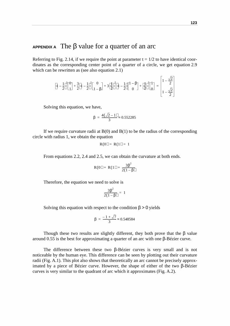
123
coor-ion 2.9
ding
tvatureprox-
APPENDIX A The β value for a quarter of an arc
Referring to Fig. 2.14, if we require the point at parameter t = 1/2 to have identical dinates as the corresponding center point of a quarter of a circle, we get equatwhich can be rewritten as (see also equation 2.1)
Solving this equation, we have,
If we require curvature radii at B(0) and B(1) to be the radius of the corresponcircle with radius 1, we obtain the equation
From equations 2.2, 2.4 and 2.5, we can obtain the curvature at both ends.
Therefore, the equation we need to solve is
Solving this equation with respect to the condition β > 0 yields
Though these two results are slightly different, they both prove that the β valuearound 0.55 is the best for approximating a quarter of an arc with one β-Bézier curve.
The difference between these two β-Bézier curves is very small and is nonoticeable by the human eye. This difference can be seen by plotting out their curradii (Fig. A.1). This plot also shows that theoretically an arc cannot be precisely apimated by a piece of Bézier curve. However, the shape of either of the two β-Béziercurves is very similar to the quadrant of arc which it approximates (Fig. A.2).
1 12---–
3 0
132--- 1 1
2---–
2 0
1 β–3
12---
2
1 12---–
1 β–
012---
3 1
0+ + +
1 22
-------–
1 22
-------–
=
β 4 2 1–( )3
------------------------ 0.552285≈=
R 0( ) R 1( ) 1= =
R 0( ) R 1( ) 3β2
2 1 β–( )--------------------= =
3β2
2 1 β–( )-------------------- 1=
β 1– 7+3
--------------------- 0.548584≈=
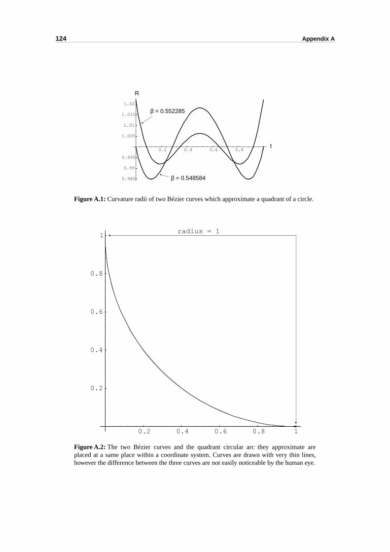
124 Appendix A
.
Figure A.1: Curvature radii of two Bézier curves which approximate a quadrant of a circle.
Figure A.2: The two Bézier curves and the quadrant circular arc they approximate areplaced at a same place within a coordinate system. Curves are drawn with very thin lines,however the difference between the three curves are not easily noticeable by the human eye
0.2 0.4 0.6 0.8 1t
0.985
0.99
0.995
1.005
1.01
1.015
1.02
R
β = 0.552285
β = 0.548584
0.2 0.4 0.6 0.8 1
0.2
0.4
0.6
0.8
1radius = 1
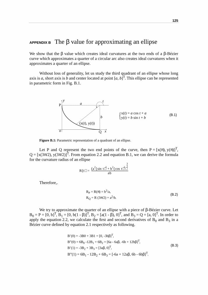
125
hen it
longd
ula
APPENDIX B The β value for approximating an ellipse
We show that the β value which creates ideal curvatures at the two ends of a β-Béziercurve which approximates a quarter of a circular arc also creates ideal curvatures wapproximates a quarter of an ellipse.
Without loss of generality, let us study the third quadrant of an ellipse whoseaxis is a, short axis is b and center located at point [a, b]T. This ellipse can be representein parametric form in Fig. B.1.
Figure B.1: Parametric representation of a quadrant of an ellipse.
Let P and Q represent the two end points of the curve, then P = [x(π), y(π)]T,Q = [x(3π/2), y(3π/2)]T. From equation 2.2 and equation B.1, we can derive the formfor the curvature radius of an ellipse
Therefore,.
We try to approximate the quarter of an ellipse with a piece of β-Bézier curve. LetB0 = P = [0, b]T, B1 = [0, b(1 - β)]T, B2 = [a(1 - β), 0]T, and B3 = Q = [a, 0]T. In order toapply the equation 2.2, we calculate the first and second derivatives of B0 and B3 in aBézier curve defined by equation 2.1 respectively as following.
a
b
x
y
o
x(t) = a cos t + ay(t) = b sin t + b{
t
(x(t), y(t))
P
Q
(B.1)
R t( ) a2 tsin( )2 b2 tcos( )2+( )32---
ab--------------------------------------------------------------=
RP = R(π) = b2/a,
RQ = R (3π/2) = a2/b.(B.2)
B’(0) = -3B0 + 3B1 = [0, -3bβ]T,
B”(0) = 6B0 -12B1 + 6B2 = [6a - 6aβ, -6b + 12bβ]T,
B’(1) = -3B2 + 3B3 = [3aβ, 0]T,
B”(1) = 6B1 - 12B2 + 6B3 = [-6a + 12aβ, 6b - 6bβ]T.
(B.3)
126 Appendix B
e twof an
woalso
With equations B.3 and 2.2, one obtain the following results.
Comparing equation B.4 and equation B.2, if we require the curvatures at thend points of the β-Bézier curve to be identical to the corresponding curvatures oellipse, we have
This is exactly the condition for a β value which creates ideal curvatures at the tends of a β-Bézier curve which approximates a quarter of a circular arc (see Appendix A). Solving this equation with respect to the condition β > 0 yields
R 0( ) 3β2
2 1 β–( )-------------------- b2
a-----⋅=
R 1( ) 3β2
2 1 β–( )-------------------- a2
b----⋅=
(B.4)
3β2
2 1 β–( )-------------------- 1=
β 1– 7+3
--------------------- 0.548584≈=
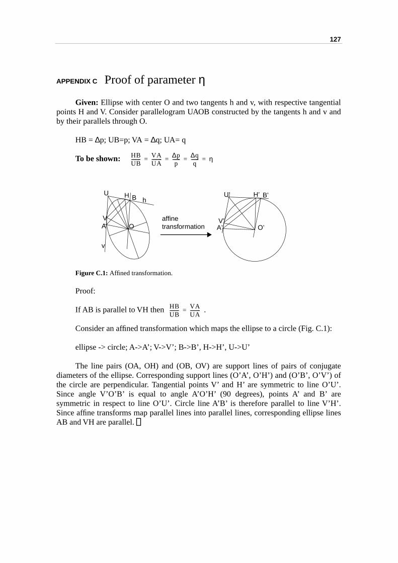
127
ntialv and
):
ate of’U’.re’. lines
APPENDIX C Proof of parameter η
Given: Ellipse with center O and two tangents h and v, with respective tangepoints H and V. Consider parallelogram UAOB constructed by the tangents h and by their parallels through O.
HB = ∆p; UB=p; VA = ∆q; UA= q
To be shown:
Figure C.1: Affined transformation.
Proof:
If AB is parallel to VH then .
Consider an affined transformation which maps the ellipse to a circle (Fig. C.1
ellipse -> circle; A->A’; V->V’; B->B’, H->H’, U->U’
The line pairs (OA, OH) and (OB, OV) are support lines of pairs of conjugdiameters of the ellipse. Corresponding support lines (O’A’, O’H’) and (O’B’, O’V’)the circle are perpendicular. Tangential points V’ and H’ are symmetric to line OSince angle V’O’B’ is equal to angle A’O’H’ (90 degrees), points A’ and B’ asymmetric in respect to line O’U’. Circle line A’B’ is therefore parallel to line V’HSince affine transforms map parallel lines into parallel lines, corresponding ellipseAB and VH are parallel.
HBUB-------- VA
UA--------- ∆p
p------- ∆q
q------- η= = = =
A
B
V
HU B’
A’ O’V’
U’ H’
affinetransformationO
h
v
HBUB-------- VA
UA---------=

128 Appendix C
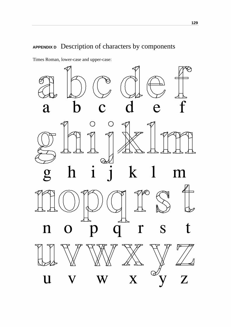
129
APPENDIX D Description of characters by components
Times Roman, lower-case and upper-case:
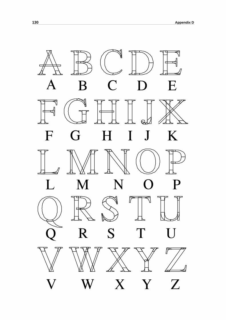
130 Appendix D
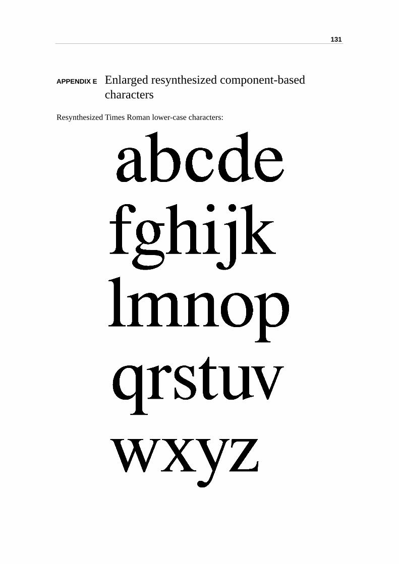
131
APPENDIX E Enlarged resynthesized component-based characters
Resynthesized Times Roman lower-case characters:
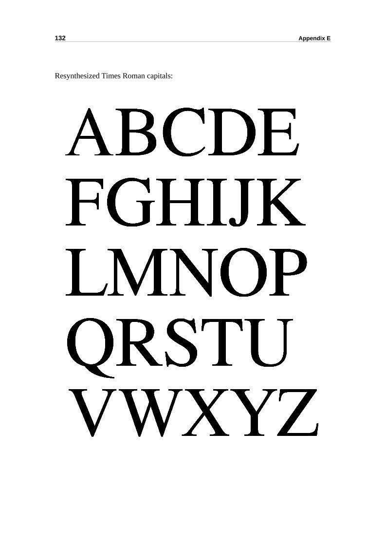
132 Appendix E
Resynthesized Times Roman capitals:
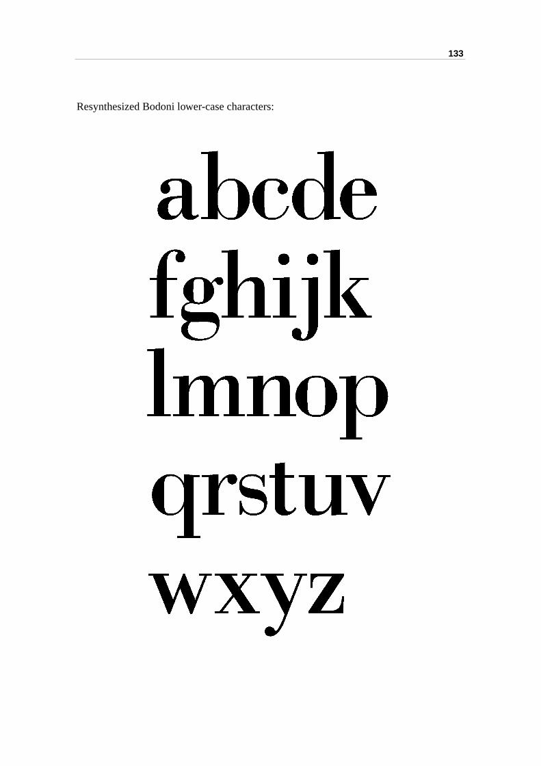
133
Resynthesized Bodoni lower-case characters:
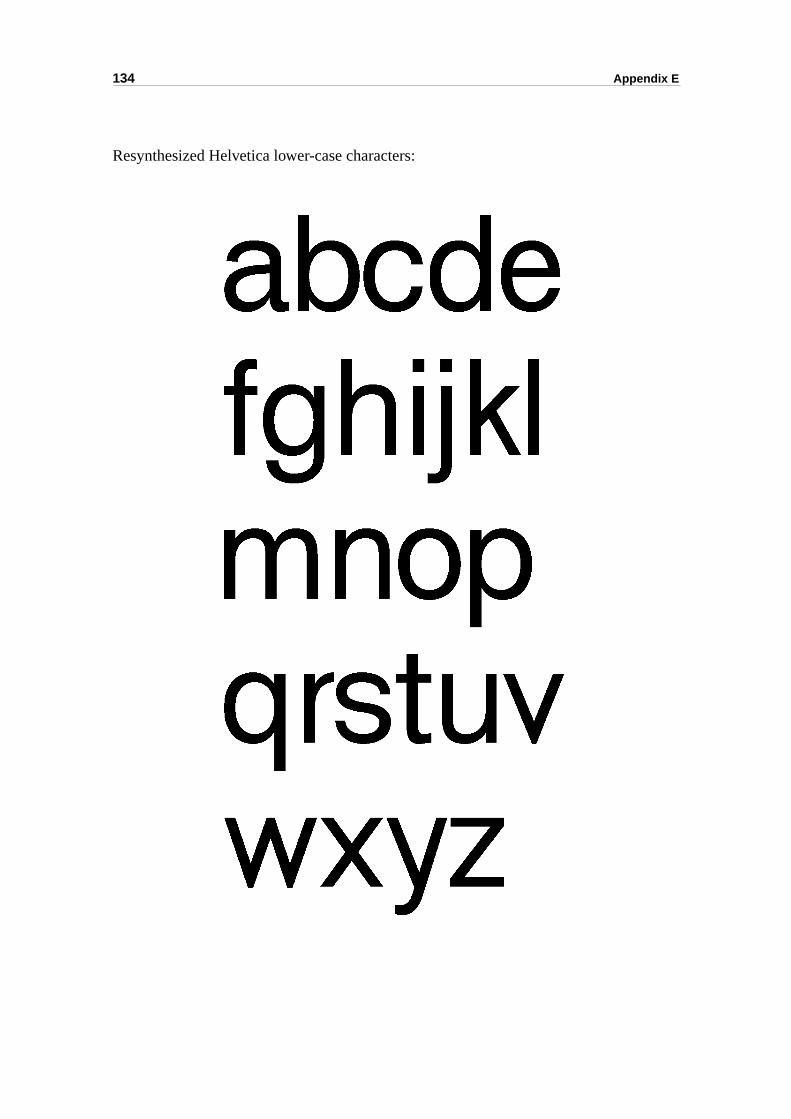
134 Appendix E
Resynthesized Helvetica lower-case characters:
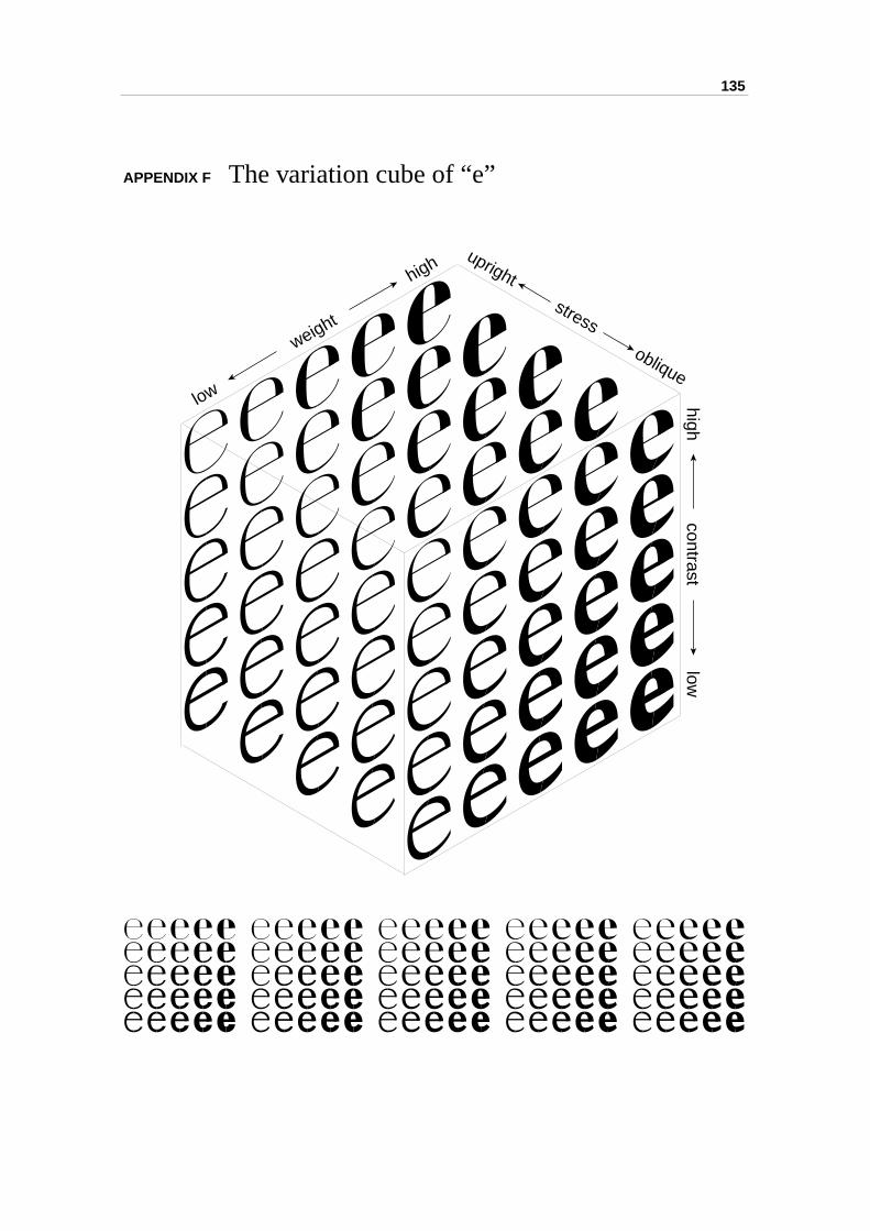
135
APPENDIX F The variation cube of “e”high
contrastlow
low
weight
highupright
stress
oblique

136 Appendix F
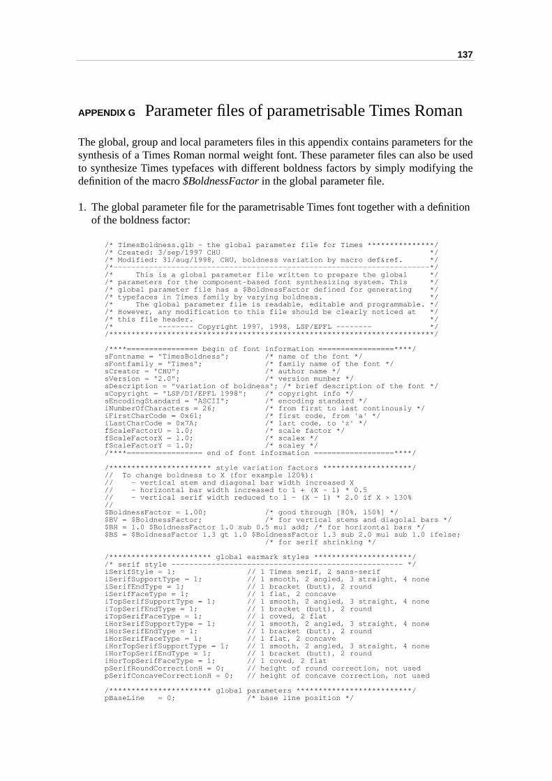
137
n
for thee used
g the
ition
APPENDIX G Parameter files of parametrisable Times Roma
The global, group and local parameters files in this appendix contains parameters synthesis of a Times Roman normal weight font. These parameter files can also bto synthesize Times typefaces with different boldness factors by simply modifyindefinition of the macro $BoldnessFactor in the global parameter file.
1. The global parameter file for the parametrisable Times font together with a definof the boldness factor:
/* TimesBoldness.glb - the global parameter file for Times ***************//* Created: 3/sep/1997 CHU *//* Modified: 31/aug/1998, CHU, boldness variation by macro def&ref. *//*-----------------------------------------------------------------------*//* This is a global parameter file written to prepare the global *//* parameters for the component-based font synthesizing system. This *//* global parameter file has a $BoldnessFactor defined for generating *//* typefaces in Times family by varying boldness. *//* The global parameter file is readable, editable and programmable. *//* However, any modification to this file should be clearly noticed at *//* this file header. *//* -------- Copyright 1997, 1998, LSP/EPFL -------- *//*************************************************************************/
/****================ begin of font information =================****/sFontname = "TimesBoldness"; /* name of the font */sFontfamily = "Times"; /* family name of the font */sCreator = "CHU"; /* author name */sVersion = "2.0"; /* version munber */sDescription = "variation of boldness"; /* brief description of the font */sCopyright = "LSP/DI/EPFL 1998"; /* copyright info */sEncodingStandard = "ASCII"; /* encoding standard */iNumberOfCharacters = 26; /* from first to last continously */iFirstCharCode = 0x61; /* first code, from 'a' */iLastCharCode = 0x7A; /* lart code, to 'z' */fScaleFactorU = 1.0; /* scale factor */fScaleFactorX = 1.0; /* scalex */fScaleFactorY = 1.0; /* scaley *//****================= end of font information ==================****/
/*********************** style variation factors ********************/// To change boldness to X (for example 120%):// - vertical stem and diagonal bar width increased X// - horizontal bar width increased to 1 + (X - 1) * 0.5// - vertical serif width reduced to 1 - (X - 1) * 2.0 if X > 130%//$BoldnessFactor = 1.00; /* good through [80%, 150%] */$BV = $BoldnessFactor; /* for vertical stems and diagolal bars */$BH = 1.0 $BoldnessFactor 1.0 sub 0.5 mul add; /* for horizontal bars */$BS = $BoldnessFactor 1.3 gt 1.0 $BoldnessFactor 1.3 sub 2.0 mul sub 1.0 ifelse; /* for serif shrinking */
/*********************** global earmark styles **********************//* serif style ---------------------------------------------------- */iSerifStyle = 1; // 1 Times serif, 2 sans-serifiSerifSupportType = 1; // 1 smooth, 2 angled, 3 straight, 4 noneiSerifEndType = 1; // 1 bracket (butt), 2 roundiSerifFaceType = 1; // 1 flat, 2 concaveiTopSerifSupportType = 1; // 1 smooth, 2 angled, 3 straight, 4 noneiTopSerifEndType = 1; // 1 bracket (butt), 2 roundiTopSerifFaceType = 1; // 1 coved, 2 flatiHorSerifSupportType = 1; // 1 smooth, 2 angled, 3 straight, 4 noneiHorSerifEndType = 1; // 1 bracket (butt), 2 roundiHorSerifFaceType = 1; // 1 flat, 2 concaveiHorTopSerifSupportType = 1; // 1 smooth, 2 angled, 3 straight, 4 noneiHorTopSerifEndType = 1; // 1 bracket (butt), 2 roundiHorTopSerifFaceType = 1; // 1 coved, 2 flatpSerifRoundCorrectionH = 0; // height of round correction, not used pSerifConcaveCorrectionH = 0; // height of concave correction, not used
/*********************** global parameters **************************/ pBaseLine = 0; /* base line position */
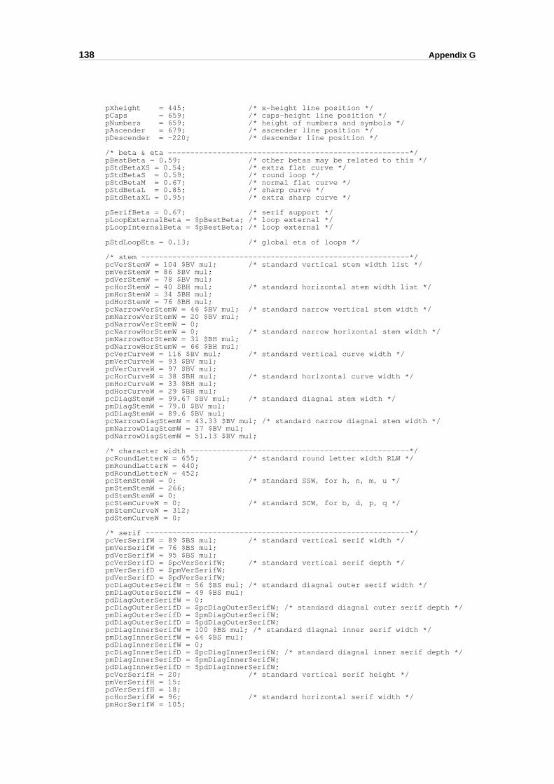
138 Appendix G
pXheight = 445; /* x-height line position */pCaps = 659; /* caps-height line position */pNumbers = 659; /* height of numbers and symbols */pAscender = 679; /* ascender line position */pDescender = -220; /* descender line position */
/* beta & eta ------------------------------------------------------*/pBestBeta = 0.59; /* other betas may be related to this */pStdBetaXS = 0.54; /* extra flat curve */pStdBetaS = 0.59; /* round loop */pStdBetaM = 0.67; /* normal flat curve */pStdBetaL = 0.85; /* sharp curve */pStdBetaXL = 0.95; /* extra sharp curve */
pSerifBeta = 0.67; /* serif support */pLoopExternalBeta = $pBestBeta; /* loop external */pLoopInternalBeta = $pBestBeta; /* loop external */
pStdLoopEta = 0.13; /* global eta of loops */
/* stem ------------------------------------------------------------*/pcVerStemW = 104 $BV mul; /* standard vertical stem width list */pmVerStemW = 86 $BV mul;pdVerStemW = 78 $BV mul;pcHorStemW = 40 $BH mul; /* standard horizontal stem width list */pmHorStemW = 34 $BH mul;pdHorStemW = 76 $BH mul;pcNarrowVerStemW = 46 $BV mul; /* standard narrow vertical stem width */pmNarrowVerStemW = 20 $BV mul;pdNarrowVerStemW = 0;pcNarrowHorStemW = 0; /* standard narrow horizontal stem width */pmNarrowHorStemW = 31 $BH mul;pdNarrowHorStemW = 66 $BH mul;pcVerCurveW = 116 $BV mul; /* standard vertical curve width */pmVerCurveW = 93 $BV mul;pdVerCurveW = 97 $BV mul;pcHorCurveW = 38 $BH mul; /* standard horizontal curve width */pmHorCurveW = 33 $BH mul;pdHorCurveW = 29 $BH mul;pcDiagStemW = 99.67 $BV mul; /* standard diagnal stem width */pmDiagStemW = 79.0 $BV mul;pdDiagStemW = 89.6 $BV mul;pcNarrowDiagStemW = 43.33 $BV mul; /* standard narrow diagnal stem width */pmNarrowDiagStemW = 37 $BV mul;pdNarrowDiagStemW = 51.13 $BV mul;
/* character width -------------------------------------------------*/pcRoundLetterW = 655; /* standard round letter width RLW */pmRoundLetterW = 440;pdRoundLetterW = 452;pcStemStemW = 0; /* standard SSW, for h, n, m, u */pmStemStemW = 266;pdStemStemW = 0;pcStemCurveW = 0; /* standard SCW, for b, d, p, q */pmStemCurveW = 312;pdStemCurveW = 0;
/* serif -----------------------------------------------------------*/pcVerSerifW = 89 $BS mul; /* standard vertical serif width */pmVerSerifW = 76 $BS mul;pdVerSerifW = 95 $BS mul;pcVerSerifD = $pcVerSerifW; /* standard vertical serif depth */pmVerSerifD = $pmVerSerifW;pdVerSerifD = $pdVerSerifW;pcDiagOuterSerifW = 56 $BS mul; /* standard diagnal outer serif width */pmDiagOuterSerifW = 49 $BS mul;pdDiagOuterSerifW = 0;pcDiagOuterSerifD = $pcDiagOuterSerifW; /* standard diagnal outer serif depth */pmDiagOuterSerifD = $pmDiagOuterSerifW;pdDiagOuterSerifD = $pdDiagOuterSerifW;pcDiagInnerSerifW = 100 $BS mul; /* standard diagnal inner serif width */pmDiagInnerSerifW = 64 $BS mul;pdDiagInnerSerifW = 0;pcDiagInnerSerifD = $pcDiagInnerSerifW; /* standard diagnal inner serif depth */pmDiagInnerSerifD = $pmDiagInnerSerifW;pdDiagInnerSerifD = $pdDiagInnerSerifW;pcVerSerifH = 20; /* standard vertical serif height */pmVerSerifH = 15;pdVerSerifH = 18;pcHorSerifW = 96; /* standard horizontal serif width */pmHorSerifW = 105;
139
pdHorSerifW = 80;pcHorSerifD = $pcHorSerifW; /* standard horizontal serif depth */pmHorSerifD = $pmHorSerifW;pdHorSerifD = $pdHorSerifW;pcHorSerifH = 23; /* standard horizontal serif height */pmHorSerifH = 20;pdHorSerifH = 18;pcTopSerifDeg = -7; /* standard slanted serif orientation */pmTopSerifDeg = 13 $BS mul;pdTopSerifDeg = 0; /* others ----------------------------------------------------------*/pcDotR = 47 $BV mul; /* standard dot radius */pmDotR = 52 $BV mul;pdDotR = 0;pcOptCor = 16; /* standard optical correction */pmOptCor = 12;pdOptCor = 16;
/* spacing ---------------------------------------------------------*/pCapitalSpacing = 187; /* capital ideal optical spacing */pSmallSpacing = 130; /* small ideal optical spacing */pCapitalStemSpacing = 217; /* capital NN spacing */pSmallStemSpacing = 147; /* small nn spacing */pCapitalCurveSpacing = 67; /* capital OO spacing */pSmallCurveSpacing = 60; /* small oo spacing */ pCapitalStemToCurveSpacing = 142; /* capital ON spacing */pSmallStemToCurveSpacing = 104; /* small on spacing */pCapitalMinimalSpacing = 43; /* capital minimum spacing */pSmallMinimalSpacing = 29; /* small minimum spacing */
2. The group parameter definition file for the parametrisable Times font:
/* TimesBoldness.grp - the group parameter file for Times ****************//* Created: 3/sep/1997 CHU *//* Modified: 31/aug/1998, CHU, boldness variation by macro def&ref. *//*-----------------------------------------------------------------------*//* This is a group parameter definition file for preparing the group *//* parameters for the component-based font synthesizing system. This *//* group parameter file contains macro names of local parameter groups *//* which will be refered to in the local parameter file. *//* Rules of macro definitions: *//* - a macro definition is a "name = value" pair, in which *//* - a name is a string begin with letter '$', *//* - value is a float value readable by the C/C++ function scanf (). *//* Naming convensions: *//* - the first letter after the '$' is a letter c/m/n indicating *//* capital/minuscule/number. *//* Macro definitions may be typeface dependent, hence group names *//* are user defined. Local parameter grouping is our method of enabling *//* coherent local feature modification amongst several characters. *//* The group parameter file is readable, editable and programmable. *//* However, any modification to this file should be clearly noticed at *//* this file header. *//* -------- Copyright 1997, 1998, LSP/EPFL -------- *//*************************************************************************/
/* group parameters' macro definition for Times *************************/
/*****************************//* standard words shortening *//*****************************/// Terminal --> Term// Junction --> Junc// Horizontal --> Hor// Vertical --> Ver// Position --> Pos// External --> Ext// Internal --> Int// Width --> W// Height --> H// Depth --> D// Radius --> R// Xdirection --> X// Ydirection --> Y
/* macros for minuscules ------------------------------------------------*/
// typical character groups and their representative characters:
140 Appendix G
// b/d/p/q --> b same loop, junction// h/m/n/u --> n same arch// c/e/o --> e round letter// k/v/w/x/y/z --> x slanted stem// f/j/r/y --> f pear terminated// i/j --> i same dot//
/* style */$iSerifStyle = 1; // this overrides the globle parameter$mBendedTermStyle = 1; // a/c/f/j/r/y, 1 - dot/pear, 2 - butt, 3 - long$mSweepStemJuncStyle = 1; // a/b/d/g/h/m/n/p/q/r/u, 1 - angled, 2 - smoothed
/* loop */$mLoopCenterXPosExt = 0.50; // b/d/p/q$mLoopCenterXPosInt = 0.45; // b/d/p/q$mLoopEtaExt = $pStdLoopEta; // b/d/p/q$mLoopEtaInt = 0.00; // b/d/p/q
/* pos */$mArmPos = 0.84; // h/m/n/u/r$mEBarPos = 0.64; // e$mABarPos = 0.68; // a
/* narrow/wide */$mHorCurveWnarrow = 0.79; // a/f$mHorCurveWwide = 1.70; // a/b/c/d/e/g/h/m/n/p/q/t/u$mDotRnarrowa = 0.87; // a/c/f/j/r/y$mDotRnarrowb = 1.00; // a/c/f/j/r/y$mVerCurveWnarrow = 0.75; // e/g/s$mVerCurveWwide = 1.05; // e$mVerSerifWnarrow = 0.84; // h/k/m/n/u,$mVerSerifWwide = 1.11; // f$mDiagSerifOuterWnarrow = 0.76; // v/w/y$mDiagSerifInnerWwide = 1.25; // k/w/y$mHorSerifWnarrow = 0.80; // z
/* connecting sweep A */$mLetterbLowerSweepA = 0.83; // b/d/p/q$mLetterbUpperSweepA = 0.60; // b/d/p/q
/* arch */$mLetternArchOuterTop = 0.61; // h/m/n/u$mLetternArchInnerTop = 0.60; // h/m/n/u$mLetternArchOuterStart = 0.76; // h/m/n/u$mLetternArchInnerStart = 0.72; // h/m/n/u$mLetternArchJuncSweepA = 0.45; // h/m/n/u
/* special earmarks */$mLetterbLowerJuncStyle = $BoldnessFactor 1.4 lt 3 $mSweepStemJuncStyle ifelse; // b, 3 - meet, if bold<1.4, otherwise spur$mLetterbUpperJuncPos = $mArmPos; // b/d/p/q/g/a
3. The local parameter file for the parametrisable Times font:
/* TimesBoldness.lcl - the local parameter file of Times *****************//* Created: 3/sep/1997 CHU *//* Modified: 31/aug/1998, CHU, boldness variation by macro def&ref. *//*-----------------------------------------------------------------------*//* This is a local parameter file written for preparing every local *//* parameters for the component-based font synthesizing system. This *//* local parameter file contains local parameters of each characters. *//* Some of the parameters are grouped to ensure coherent local feature *//* modification. *//* Local parameter names may not be understandable even with the *//* comments. Fortunately, they are not necessary for users who wants to *//* derive new typeface just by varing global typeface features, such as *//* wight, width, contrast, stress and height proportion. To better *//* understand local parameters, one should read the charXX.cp files. *//* The local parameter file is readable, editable and programmable. *//* However, any modification to this file should be clearly noticed at *//* this file header. *//* -------- Copyright 1997, 1998, LSP/EPFL -------- *//*************************************************************************/
char61 // "a"{ variation = 1; // 1 - double storey; 2 - single storey
141
pdx1 = 0.54; // main width, belly to stem pdx2 = 0.50; // secondary width, bulb to stem Tr1c1 = $mBendedTermStyle; // 1 dot/pear, 2, 3 butt Tr2c2 = 1; // 1 pointed, 2 butt down, 3 butt right, // 4 sans-serif, 5 slab-serif Jr1c2 = 1; // 1 angled, 2 smoothed, 3 loop Jr2c2 = $mSweepStemJuncStyle; // 1 angled, 2 smoothed dotAngle = -10; // Degree headWidth = 0.60; // in proportion to StdVerStemW crr1 = 0.03; ppp1 = 0.50; // top arc center ppp2 = 0.71; // top arc start ppp3 = 0.77; // dot center height ppp4 = 0.15; // tail bottom-most x ppp5 = 0.45; // tail right-most x ppp6 = 0.12; // tail right-most y ppp7 = 0.60; // tail curve A.x ppp8 = 0.25; // belly left-most height ppp9 = 0.60; // s6 curve A.x pppA = 0.45; // belly bottom-most x pppB = 0.42; // belly inner bottom-most x pppC = 0.35; // s8 curve A.x pppD = 0.85; // s2 curve A.x pppE = 0.18; // tail start y pppG = 1 $mArmPos sub; // s8 arrival y, = 1 - ArmPos pppH = $mABarPos; // a-bar position pppJ = 0.45; // smoothing edge1, related to dx1 pppK = 0.10; // smoothing edge2, related to pXheight pppL = 0.15; // smoothing tang1, related to dx1 pppM = 0.10; // smoothing tang2, related to pXheight narrow1 = $mHorCurveWnarrow; // narrow minuscule horizontal curve width narrow2 = $mDotRnarrowa; // narrow minuscule dot width a narrow3 = $mDotRnarrowb; // narrow minuscule dot width b wide1 = $mHorCurveWwide; // wide minuscule horizontal curve width}char62 // "b"{ Tr1c1 = $iSerifStyle; // 1 has topserif, 2 no topserif Tr2c1 = 1; // 1 spur, 2 no spur, 3 half foot serif Jr1c1 = $mSweepStemJuncStyle; // 1 angled, 2 smoothed Jr2c1 = $mLetterbLowerJuncStyle; // 1 angled with spur, 2 smoothed, // 3 angled and meet eta1 = $mLoopEtaExt neg; // loop eta external, - 0.15 eta2 = $mLoopEtaInt; // loop eta internal ppp1 = $mLoopCenterXPosExt; // center1.x of the loop ppp2 = $mLoopCenterXPosInt; // center2.x of the loop ppp3 = 0.13; // junction Tr2c1 height ppp4 = 0.16; // junction Tr2c1 internal height ppp5 = $mLetterbLowerSweepA; // beta-curve control A of sweep s3 ppp6 = $mLetterbUpperSweepA; // beta-curve control A of sweep s4 ppp7 = $mLetterbUpperJuncPos; // arm position of Jr1c1, b/d/p/q spurAngle = 13; // Degree wide1 = $mHorCurveWwide; // wide minuscule hor curve width, a/b/n}char63 // "c"{ pdx1 = 0.88; // main width, half-loop to tail pdx2 = 0.84; // secondary width, half-loop to bulb Tr1c1 = $mBendedTermStyle; // 1 dot, 2, 3 butt Tr2c1 = 1; // 1 butt eta1 = -0.02; // loop external, non-grp eta2 = 0.10; // loop internal, non-grp dotAngle = 10; // Degree tailAngle = 30; // Degree tailWidth = 0.28; // tail width ppp1 = 0.50; // loop center external ppp2 = 0.55; // loop center internal ppp3 = 1.30; // bottom arc width correction ppp4 = 0.78; // dot center y ppp5 = 0.85; // s2 curve A.x ppp6 = 0.35; // tail y ppp7 = 0.65; // tail s3 curve A.x pppJ = 0.40; // smoothing edge1, related to dx1 pppK = 0.10; // smoothing edge2, related to pXheight pppL = 0.15; // smoothing tang1, related to dx1 pppM = 0.10; // smoothing tang2, related to pXheight wide1 = $mHorCurveWwide; // wide minuscule hor curve width a/b/c/n narrow1 = $mDotRnarrowa; // narrow minuscule dot radius a narrow2 = $mDotRnarrowb; // narrow minuscule dot radius b}char64 // "d"
142 Appendix G
{ pdx1 = 1.0; // main width, half-loop to stem Tr1c1 = $iSerifStyle; // 1 has topserif, 2 no serif Tr2c1 = $iSerifStyle; // 1 has serif, 2 no serif Jr1c1 = $mSweepStemJuncStyle; // 1 angled link, 2 smoothed link Jr2c1 = $mSweepStemJuncStyle; // 1 angled link, 2 smoothed link eta1 = $mLoopEtaExt neg; // loop eta external eta2 = $mLoopEtaInt; // loop eta internal ppp1 = $mLoopCenterXPosExt; // center1.x of the loop ppp2 = $mLoopCenterXPosInt; // center2.x of the loop ppp3 = 0.83; // s3 Pd.y ppp4 = 0.70; // s3 Qd.y ppp5 = $mLetterbLowerSweepA; // s3 curve A.x ppp6 = $mLetterbUpperSweepA; // s4 curve A.x ppp7 = 1 $mLetterbUpperJuncPos sub; // arm position of Jr2c1, b/d/p/q spurAngle = 13; // bottom serif slant, never zero. wide1 = $mHorCurveWwide; // wide hor curve width, a/b/c/n}char65 // "e"{ pdx1 = 0.91; // main width, half-loop to tail pdx2 = 0.86; // secondary width, half-loop to corner Tr2c2 = 1; // 1 butt tail Jr1c1 = 1; // 1 perpendicular link Jr1c2 = 1; // 1 squared corner eta1 = 0.00; // loop eta external eta2 = 0.19; // loop eta internal tailAngle = 30; // Degree tailWidth = 0.28; // tail width ppp1 = 0.50; // loop center external ppp2 = 0.51; // loop center internal ppp3 = 1.30; // bottom arc width correction ppp4 = 0.35; // tail right-most y ppp5 = 0.65; // tail s3 curve A.x ppp6 = $mEBarPos; // e-bar position narrow1 = $mVerCurveWnarrow; // narrow minuscule vertical curve width wide1 = $mVerCurveWwide; // wide minuscule vertical curve width wide2 = $mHorCurveWwide; // wide munuscule horizontal curve width}char66 // "f"{ pdx1 = 0.41; // main width, stem to bulb Tr1c1 = $mBendedTermStyle; // 1 dot, 2 butt, 3 long squared Tr2c1 = $iSerifStyle; // 1 serif, 2 no serif dotAngle = 30; // Degree ppp1 = 0.19; // bar left-most ppp2 = 0.27; // bar right-most ppp3 = 0.90 $BV 1.0 sub 0.08 mul sub; // dot center y, adjusted to boldness ppp4 = 0.50; // top arc internal extreme x ppp5 = 0.65; // top arc external extreme x ppp6 = 0.85; // top arc start internal y ppp7 = 0.69; // top arc start external y ppp8 = 0.65; // top arc s5 curve A.x pppJ = 0.40; // smoothing edge1, related to dx1 pppK = 0.07; // smoothing edge2, related to pXheight pppL = 0.15; // smoothing tang1, related to dx1 pppM = 0.05; // smoothing tang2, related to pXheight narrow1 = $mHorCurveWnarrow; // narrow minuscule horizontal curve width narrow2 = $mDotRnarrowa; // narrow minuscule dot ridus a narrow3 = $mDotRnarrowb; // narrow minuscule dot ridus b wide1 = $mVerSerifWwide; // wide minuscule vertical serif width/depth}char67 // "g"{ variation = 1; // 1 - double storey; 2 - single storey Tr1c1 = 1; // 1 bar, 2 ear (sw + dot + smooth); x0 = 245; // orginal /* if variation == 1 */ eta1 = 0.00; // loop eta external eta2 = 0.19; // loop eta internal pdx1 = 0.28; // main width, loop center to loop right pdx2 = 0.50; // secondary width, to belly right pdx3 = 0.50; // third width ppp1 = 0.66; // loop center y ppp2 = 0.90; // currection of curve width of loop s0 ppp3 = 0.90; // bar height ppp4 = 0.15; // s2 Pd.x ppp5 = 0.10; // s2 Qd.x ppp6 = 0.15; // s2 Pa.y ppp7 = 0.68; // currection of curve width of s2.PaQa ppp8 = 0.20; // s2 Qa.y
143
ppp9 = 0.47; // s2 curve A.y pppA = 0.10; // s3 Pa.x pppB = 0.12; // s3 Qa.y --- old y1 pppC = 0.30; // s3 Qa.x pppD = 1.00; // s3 curve A.y pppE = 0.32; // currection of curve width of s4.PaQa pppF = 0.32; // s4 Pa.y pppG = 0.22; // s4 Qa.y pppH = 1.00; // s4 curve A.y pppI = 0.00; // s5 Pa.x pppJ = 0.20; // s5 Qa.x pppK = 0.78; // currection of curve width of s6.PaQa pppL = 0.42; // s6 Pa.y pppM = 0.52; // s6 Qa.y pppN = 0.15; // s7 Pa.x pppO = 0.22; // s7 Qa.x pppP = 0.40; // s7 curve A.y narrow1 = $mVerCurveWnarrow; // narrow minuscule vertical curve width narrow2 = $mHorCurveWnarrow; // narrow minuscule horizontal curve width wide1 = $mHorCurveWwide; // wide munuscule hor curve width}char68 // "h"{ pdx1 = 1.0; // main width, stem to stem Tr1c1 = $iSerifStyle; // 1 has topserif, 2 sans-serif Tr2c1 = $iSerifStyle; // 1 has serif, 2 sans-serif Tr2c2 = $iSerifStyle; // 1 has serif, 2 sans-serif Jr1c1 = $mSweepStemJuncStyle; // 1 angled link, 2 smoothed link ppp1 = $mLetternArchOuterTop; // arc top outer x ppp2 = $mLetternArchInnerTop; // arc top inner x ppp3 = $mLetternArchOuterStart; // s5 Pd.y ppp4 = $mLetternArchInnerStart; // s5 Qd.y ppp5 = $mLetternArchJuncSweepA; // s6 curve A.x ppp6 = $mArmPos; // arm position of Jr1c1 wide1 = $mHorCurveWwide; // wide minuscule hor curve width narrow1 = $mVerSerifWnarrow; // narrow minuscule vertical serif width}char69 // "i"{ pdx1 = 0.02; // main width, stem to dot center Tr1c1 = 1; // 1 round dot, 2 square dot Tr2c1 = $iSerifStyle; // 1 has topserif, 2 sans-serif Tr3c1 = $iSerifStyle; // 1 has serif, 2 sans-serif narrow1 = $mDotRnarrowa; // narrow minuscule dot radius a}char6A // "j"{ pdx1 = 0.40; // main width, stem to tail bulb pdx2 = 0.02; // secondary width, stem to dot center Tr1c1 = 1; // 1 round dot, 2 square dot Tr2c1 = $iSerifStyle; // 1 has topserif, 2 sans-serif Tr3c1 = $mBendedTermStyle; // 1 dot/pear, 2 butt, 3 long dotAngle = 45 $BV 1.0 sub 10 mul sub; // bulb, Degree, adjusted to boldness ppp1 = 0.40; // tail left start s2 Pd.y ppp2 = 0.15; // tail right start s2 Qd.y ppp3 = 0.50; // tail bottom s2 Pa.x ppp4 = 0.65; // tail bottom s2 Qa.x ppp5 = 0.73 $BV 1.0 sub 0.2 mul sub; // bulb center y, adjusted to boldness ppp6 = 0.66; // tail s4 curve A.x pppJ = 0.40; // smoothing edge1, related to dx1 pppK = 0.07; // smoothing edge2, related to pXheight pppL = 0.10; // smoothing tang1, related to dx1 pppM = 0.05; // smoothing tang2, related to pXheight narrow1 = $mDotRnarrowa; // narrow minuscule dot radius a narrow2 = $mDotRnarrowb; // narrow minuscule dot radius a}char6B // "k"{ pdx1 = 0.63; // main width, stem to right-bottom pdx2 = 0.62; // secondary width, to right-up Tr1c1 = $iSerifStyle; // 1 has topserif, 2 sans-serif Tr1c2 = $iSerifStyle; // 1 has serif, 2 sans-serif Tr2c1 = $iSerifStyle; // 1 has serif, 2 sans-serif Tr2c2 = $iSerifStyle; // 1 has serif, 2 sans-serif Jr1c1 = 1; // 1 singla junction, 2 double junction ppp1 = 0.85; // junction center x ppp2 = 0.60; // junction center y wide1 = $mDiagSerifInnerWwide; // wide diag serif inner width narrow1 = $mVerSerifWnarrow; // narrow minuscule vertical serif width}
144 Appendix G
char6C // "l"{ Tr1c1 = $iSerifStyle; // 1 has topserif, 2 sans-serif Tr2c1 = $iSerifStyle; // 1 has serif, 2 sans-serif}char6D // "m"{ pdx1 = 1.0; // main width, stem to stem Tr1c1 = $iSerifStyle; // 1 has topserif, 2 sans-serif Tr2c1 = $iSerifStyle; // 1 has serif, 2 sans-serif Tr2c2 = $iSerifStyle; // 1 has serif, 2 sans-serif Tr2c3 = $iSerifStyle; // 1 has serif, 2 sans-serif Jr1c1 = $mSweepStemJuncStyle; // 1 angled link, 2 smoothed link Jr1c2 = $mSweepStemJuncStyle; // 1 angled link, 2 smoothed link ppp1 = $mLetternArchOuterTop; // arc top outer x ppp2 = $mLetternArchInnerTop; // arc top inner x ppp3 = $mLetternArchOuterStart; // s5 Pd.y ppp4 = $mLetternArchInnerStart; // s5 Qd.y ppp5 = $mLetternArchJuncSweepA; // s6 curve A.x ppp6 = $mArmPos; // arm position of Jr1c2/Jr1c2 wide1 = $mHorCurveWwide; // wide minuscule hor curve width narrow1 = $mVerSerifWnarrow; // narrow minuscule vertical serif width}char6E // "n"{ pdx1 = 1.0; // main width, stem to stem Tr1c1 = $iSerifStyle; // 1 has topserif, 2 sans-serif Tr2c1 = $iSerifStyle; // 1 has serif, 2 sans-serif Tr2c2 = $iSerifStyle; // 1 has serif, 2 sans-serif Jr1c1 = $mSweepStemJuncStyle; // 1 angled link, 2 smoothed link ppp1 = $mLetternArchOuterTop; // arc top outer x ppp2 = $mLetternArchInnerTop; // arc top inner x ppp3 = $mLetternArchOuterStart; // s5 Pd.y ppp4 = $mLetternArchInnerStart; // s5 Qd.y ppp5 = $mLetternArchJuncSweepA; // s6 curve A.x ppp6 = $mArmPos; // arm position of Jr1c1 wide1 = $mHorCurveWwide; // wide minuscule hor curve width narrow1 = $mVerSerifWnarrow; // narrow minuscule serif width h/n/m/u}char6F // "o"{ eta1 = 0.00; // loop eta external eta2 = $pStdLoopEta 0.02 add; // loop eta internal, a little stress}char70 // "p"{ pdx1 = 1.0; // main width, stem to curve Tr1c1 = $iSerifStyle; // 1 has topserif, 2 no serif Tr2c1 = $iSerifStyle; // 1 has serif, 2 no serif Jr1c1 = $mSweepStemJuncStyle; // 1 angled link, 2 smoothed link Jr2c1 = $mSweepStemJuncStyle; // 1 andled link, 2 smoothed link eta1 = $mLoopEtaExt neg; // loop eta external eta2 = $mLoopEtaInt; // loop eta internal ppp1 = $mLoopCenterXPosExt; // loop center1.x ppp2 = $mLoopCenterXPosInt; // loop center2.x ppp3 = 0.17; // s3 Pd.y ppp4 = 0.25; // s3 Qd.y ppp5 = $mLetterbLowerSweepA; // s3 curve A.x ppp6 = $mLetterbUpperSweepA; // s4 curve A.x ppp7 = $mLetterbUpperJuncPos; // arm position of Jr1c1, b/d/p/q/... spurAngle = 13; // top serif slant wide1 = $mHorCurveWwide; // wide minuscule hor curve width narrow1 = $mVerSerifWnarrow; // narrow minuscule serif width h/n/m/u}char71 // "q"{ pdx1 = 1.0; // main width, stem to curve Tr1c1 = $iSerifStyle; // 1 has topserif, 2 no serif Tr2c1 = $iSerifStyle; // 1 has serif, 2 no serif Jr1c1 = $mSweepStemJuncStyle; // 1 angled link, 2 smoothed link Jr2c1 = $mSweepStemJuncStyle; // 1 andled link, 2 smoothed link eta1 = $mLoopEtaExt neg; // loop eta external eta2 = $mLoopEtaInt; // loop eta internal ppp1 = $mLoopCenterXPosExt; // loop center1.x ppp2 = $mLoopCenterXPosInt; // loop center2.x ppp3 = 0.85; // s3 Pd.y ppp4 = 0.70; // s3 Qd.y ppp5 = $mLetterbLowerSweepA; // s3 curve A.x ppp6 = $mLetterbUpperSweepA; // s4 curve A.x ppp7 = 1.80; // top spur height correctness of Opt ppp8 = 1 $mLetterbUpperJuncPos sub; // arm position of Jr2c1, b/d/p/q/h/n/m
145
spurAngle = 20; // top spur slant, Degree wide1 = $mHorCurveWwide; // wide minuscule hor curve width}char72 // "r"{ pdx1 = 0.39; // main width, stem to bulb center Tr1c1 = $iSerifStyle; // 1 has topserif, 2 sans-serif Tr2c1 = $iSerifStyle; // 1 has serif, 2 sans-serif Tr1c2 = $mBendedTermStyle; // 1 dot/pear, 2 butt, 3 long Jr1c1 = $mSweepStemJuncStyle; // 1 angled link, 2 smoothed link dotAngle = 30; // Degree ppp1 = $BV 1.0 ge 0.98 $BV 1.0 sub 0.04 mul sub 0.98 ifelse; // dot y, adjusted to boldness ppp2 = 0.60; // arc s4 curve A.x ppp3 = $mArmPos; // arm position of Jr1c1 pppJ = 0.60; // smoothing edge1, related to dx1 pppK = 0.07; // smoothing edge2, related to pXheight pppL = 0.10; // smoothing tang1, related to dx1 pppM = 0.10; // smoothing tang2, related to pXheight wide1 = $mHorCurveWwide; // wide minuscule hor curve width narrow1 = $mVerSerifWnarrow; // narrow minuscule ver serif width h/n/m/u narrow2 = $mDotRnarrowa; // narrow minuscule dot radius a narrow3 = $mDotRnarrowb; // narrow minuscule dot radius b}char73 // "s"{ pdx1 = 0.52; // main width, left curve to right curve pdx2 = 0.57; // secondary width, left tail to right curve pdx3 = 0.51; // secondary width, left curve to right tail Tr1c1 = $iSerifStyle; // 1 serif-like, 2 butt Tr2c1 = $iSerifStyle; // 1 serif-like, 2 butt crr1 = 0.12; // special curved stroke stress ppp1 = 0.35; // y1, right tail height ppp2 = 0.38; // y2, right curve height ppp3 = 0.31; // y3, right tail height ppp4 = 0.36; // y4, left curve height ppp5 = 0.81; // s1 curve A.x ppp6 = 0.62; // s2 arrival, s3 start ppp7 = 0.60; // s4 arrival, s5 start ppp8 = 0.81; // s6 curve A.x pppJ = 1.00; // smoothing edge1, related to pXheight pppK = 0.43; // smoothing edge2, related to dx1 pppL = 0.02; // smoothing tang1, related to pXheight pppM = 0.15; // smoothing tang2, related to dx1 tailAngle = 30; // Degree, for sans-serif narrow1 = $mVerCurveWnarrow; // narrow minuscule vertical curve width narrow2 = $mHorCurveWnarrow; // narrow minuscule horizontal curve width}char74 // "t"{ Tr1c1 = 1; // 1 concave head, 2 cross bar, // 3 cross bar with possibly slanted end Tr2c1 = 1; // 1 pointed tail, 2 butt tailAngle = 45; // Degree tailWidth = 0.50; // tail width ppp1 = 0.22; // bar right-most ppp2 = 0.28; // tail right-most ppp3 = 0.13; // bar left-most ppp4 = 0.29; // stem top extension ppp5 = 0.15; // tail left-most y ppp6 = 0.20; // tail start s2 Pd.y ppp7 = 0.25; // tail start s2 Qd.y ppp8 = 0.45; // tail bottom most external x ppp9 = 0.41; // tail bottom most internal x pppA = 0.40; // tail s3 curve A.x pppB = 0.55; // top correction left pppC = 0.80; // top correction top pppD = 0.62; // top correction S4 curve A wide1 = $mHorCurveWwide; // wide minuscule hor curve width}char75 // "u"{ pdx1 = 1.0; // main width, stem to stem Tr1c1 = $iSerifStyle; // 1 has serif, 2 sans-serif Tr1c2 = $iSerifStyle; // 1 has serif, 2 sans-serif Tr2c2 = $iSerifStyle; // 1 has topserif, 2 sans-serif Jr2c2 = $mSweepStemJuncStyle; // 1 angled link, 2 smoothed link ppp1 = $mLetternArchOuterTop; // arc bottom outer x ppp2 = $mLetternArchInnerTop; // arc botton inner x ppp3 = $mLetternArchOuterStart; // s3 Pd.y ppp4 = $mLetternArchInnerStart; // s3 Qd.y
146 Appendix G
ppp5 = $mLetternArchJuncSweepA 1 0.1 iplt; // s4 curve A.x, iplt ($, 1, 0.1), bigger than that in 'n' ppp6 = 1 $mArmPos sub; // arm position of Jr2c2 wide1 = $mHorCurveWwide; // wide minuscule hor curve width narrow1 = $mVerSerifWnarrow; // narrow minuscule serif ver width h/n/m/u}char76 // "v"{ pdx1 = 0.73; // main width, left to right Tr1c1 = $iSerifStyle; // 1 has serif, 2 sans-serif Tr1c2 = $iSerifStyle; // 1 has serif, 2 sans-serif ppp1 = 0.58; // s0 start x ppp2 = 0.44; // s1 start x narrow1 = $mDiagSerifOuterWnarrow; // narrow diag serif outer width, v/w/y}char77 // "w"{ pdx1 = 0.71; // main width, similar to v pdx2 = 0.15; // secondary width, overlap of two 'v' Tr1c1 = $iSerifStyle; // 1 has serif, 2 sans-serif Tr1c2 = $iSerifStyle; // 1 has serif, 2 sans-serif Tr1c3 = $iSerifStyle; // 1 has serif, 2 sans-serif Jr1c2 = 1; // not used, equivalent to Tr1c2 ppp1 = 0.56; // s0 start x ppp2 = 0.42; // s1 start x narrow1 = $mDiagSerifOuterWnarrow; // narrow diag serif outer width, v/w/y wide1 = $mDiagSerifInnerWwide; // wide diag serif inner width}char78 // "x"{ pdx1 = 0.74; // main width, bottom left to right Tr1c1 = $iSerifStyle; // 1 has serif, 2 sans-serif Tr1c2 = $iSerifStyle; // 1 has serif, 2 sans-serif Tr2c1 = $iSerifStyle; // 1 has serif, 2 sans-serif Tr2c2 = $iSerifStyle; // 1 has serif, 2 sans-serif crr1 = 0.15; // optical crr for bottom-left, stem s6 crr2 = 0.45; // crr for top-left, s1 crr3 = 0.05; // crr for top-right, s0}char79 // "y"{ pdx1 = 0.77; // main width, top left to right pdx2 = 0.0; // secondary width, left to tail bulb center Tr1c1 = $iSerifStyle; // 1 has serif, 2 sans-serif Tr1c2 = $iSerifStyle; // 1 has serif, 2 sans-serif Tr2c1 = $mBendedTermStyle; // 1 dot/pear, 2 butt, 3 long dotAngle = 75; // Degree ppp1 = 0.61; // stem s0 start x ppp2 = 0.42; // stem s1 start x ppp3 = 0.35; // stem s1 start y ppp4 = 0.78 $BV 1.0 sub 0.2 mul sub; // dot center y, adjusted to boldness ppp5 = 0.05; // tail bottom-most x ppp6 = 0.20; // tail s6 curve A.x new !!! pppJ = 0.30; // smoothing edge1, related to dx1 pppK = 0.10; // smoothing edge2, related to pXheight pppL = 0.15; // smoothing tang1, related to dx1 pppM = 0.10; // smoothing tang2, related to pXheight narrow1 = $mDiagSerifOuterWnarrow; // narrow diag serif outer width, v/w/y narrow2 = $mDotRnarrowa; // narrow minuscule dot radius a narrow3 = $mDotRnarrowb; // narrow minuscule dot radius b wide1 = $mDiagSerifInnerWwide; // wide diag serif inner width}char7A // "z"{ pdx1 = 0.78; // main width, bottom left to bottom right pdx2 = 0.02; // secondary width, bottom left to top left pdx3 = 0.09; // secondary, bottom right to top right Tr1c1 = $iSerifStyle; // 1 has serif, 2 sans-serif Tr2c2 = $iSerifStyle; // 1 has serif, 2 sans-serif Jr1c2 = 1; // no use for Times Jr2c1 = 1; // no use for Times angle1 = -5; // topBeakAngle Degree angle2 = -5; // bottom Beak Angle Degree ppp1 = 0.05; // top MiterLimit, in ppp to StdDiagStemW ppp2 = 0.05; // bottomMiterLimit, in ppp to StdDiagStemW narrow1 = $mHorSerifWnarrow; // narrow hor serif width}
a Ph.D effortnthesis
uangsing
ization
ciencearch andmatic
cience
fromith an
jing
Curriculum Vitae
I was born on June 10, 1966, and I hold the Chinese nationality.
Since Jul. 1995, I have been working as a research assistant as well as candidate at the Peripheral Systems Laboratory (LSP) of EPFL. My main researchwas focussed on the design and development of a new parametrisable font sysystem.
From Oct. 1994 to Jun. 1995, I worked as a technical consultant at the HuaGElectronics Group Inc. (Beijing) for the development of a Chinese photocomposystem. I was in charge of the high-quality high-speed Chinese character rastertechnology.
From Sep. 1992 to Aug. 1994, I was a research assistant at the Computer SDepartment of Nanjing University (Nanjing, China). I took part in a national reseproject related to the flexible application of Chinese outline fonts. I designeddeveloped an automatic hinting system for Chinese outline fonts based on autostroke separation.
From Sep. 1991 to Aug. 1992, I was a teaching assistant at the Computer SDepartment of Tsinghua University (Beijing).
In 1991, I received a Master degree in Computer Science and Application Nanjing University. For the thesis, I developed a prototype PostScript interpreter wextension to describe and print Chinese outline characters.
In 1988, I received my Bachelor degree in Computer Science from NanUniversity.