OIML R 61-1
48
Automatic gravimetric filling instruments Part 1: Metrological and technical requirements - Tests Doseuses pondérales à fonctionnement automatique Partie 1: Exigences métrologiques et techniques - Essais OIML R 61-1 Edition 2004 (E) OIML R 61-1 Edition 2004 (E) ORGANISATION INTERNATIONALE DE MÉTROLOGIE LÉGALE INTERNATIONAL ORGANIZATION OF LEGAL METROLOGY INTERNATIONAL RECOMMENDATION
Transcript of OIML R 61-1
Automatic gravimetric filling instruments
Part 1: Metrological and technical requirements - Tests
Doseuses pondérales à fonctionnement automatique
Partie 1: Exigences métrologiques et techniques - Essais
OIM
L R
61-
1 Ed
ition
2004
(E)
OIML R 61-1Edition 2004 (E)
ORGANISATION INTERNATIONALE
DE MÉTROLOGIE LÉGALE
INTERNATIONAL ORGANIZATION
OF LEGAL METROLOGY
INTERNATIONAL
RECOMMENDATION
OIML R 61-1: 2004 (E)
2
Contents
Foreword .......................................................................................................................................................................... 4
Terminology (Terms and definitions) ................................................................................................................ 5
1 General ................................................................................................................................................... 11
1.1 Scope .................................................................................................................................................................. 111.2 Terminology ....................................................................................................................................................... 11
2 Metrological requirements..................................................................................................................... 11
2.1 Accuracy classes ................................................................................................................................................ 112.2 Limits of error ................................................................................................................................................... 112.3 Particle mass correction ................................................................................................................................... 122.4 Maximum permissible preset value error (setting error) MPSE ................................................................... 122.5 Maximum permissible error for influence factor tests (MPE) ...................................................................... 122.6 Minimum capacity (Min) ................................................................................................................................. 122.7 Rated minimum fill (Minfill) ........................................................................................................................... 132.8 Influence factors ............................................................................................................................................... 132.9 Units of measurement ...................................................................................................................................... 14
3 Technical requirements .......................................................................................................................... 14
3.1 Suitability for use .............................................................................................................................................. 143.2 Security of operation ........................................................................................................................................ 143.3 Indication of weighing results ......................................................................................................................... 143.4 Fill setting device .............................................................................................................................................. 153.5 Final feed cut-off device ................................................................................................................................... 153.6 Feeding device ................................................................................................................................................... 153.7 Load receptor .................................................................................................................................................... 153.8 Zero-setting and tare devices ........................................................................................................................... 153.9 Equilibrium mechanism ................................................................................................................................... 173.10 Descriptive markings ........................................................................................................................................ 173.11 Verification marks ............................................................................................................................................. 183.12 Control instrument ........................................................................................................................................... 18
4 Requirements for electronic instruments............................................................................................. 18
4.1 General requirements ....................................................................................................................................... 184.2 Functional requirements .................................................................................................................................. 194.3 Examination and tests ...................................................................................................................................... 19
5 Metrological controls.............................................................................................................................. 20
5.1 General .............................................................................................................................................................. 205.2 Type approval .................................................................................................................................................... 205.3 Initial verification ............................................................................................................................................. 215.4 Subsequent verification .................................................................................................................................... 225.5 In-service inspection ......................................................................................................................................... 22
OIML R 61-1: 2004 (E)
3
6 Test methods ........................................................................................................................................... 22
6.1 Determination of the mass of individual fills ................................................................................................. 226.2 Conduct of material tests ................................................................................................................................. 226.3 Number of fills .................................................................................................................................................. 236.4 Accuracy of standards ...................................................................................................................................... 236.5 Material test methods ....................................................................................................................................... 236.6 Preset value ....................................................................................................................................................... 246.7 Mass and average value of the test fill ............................................................................................................ 246.8 Deviation for automatic weighing ................................................................................................................... 246.9 Preset value error for automatic weighing ...................................................................................................... 24
Annex A
Testing procedures for automatic gravimetric filling instruments................................................................ 25
A.1 Administrative examination ............................................................................................................................. 25A.2 Examination for initial verification ................................................................................................................. 25A.3 General test requirements ................................................................................................................................ 25A.4 Test program ..................................................................................................................................................... 26A.5 Static tests ......................................................................................................................................................... 27A.6 Influence factor tests and disturbance tests ................................................................................................... 30A.7 Span stability test .............................................................................................................................................. 41A.8 Procedure for material tests ............................................................................................................................. 42
Bibliography ....................................................................................................................................................... 45
OIML R 61-1: 2004 (E)
4
Foreword
The International Organization of Legal Metrology(OIML) is a worldwide, intergovernmental organizationwhose primary aim is to harmonize the regulations and
metrological controls applied by the national metrologicalservices, or related organizations, of its Member States.
The two main categories of OIML publications are:
• International Recommendations (OIML R), which aremodel regulations that establish the metrological charac-teristics required of certain measuring instruments andwhich specify methods and equipment for checking theirconformity; the OIML Member States shall implementthese Recommendations to the greatest possible extent;
• International Documents (OIML D), which are inform-ative in nature and intended to improve the work of themetrology services.
OIML Draft Recommendations and Documents are devel-oped by technical committees or subcommittees which areformed by Member States. Certain international and regionalinstitutions also participate on a consultation basis.
Cooperative agreements are established between OIML andcertain institutions, such as ISO and IEC, with the objective
of avoiding contradictory requirements; consequently, manu-facturers and users of measuring instruments, test labor-atories, etc. may apply simultaneously OIML publicationsand those of other institutions.
International Recommendations and International Docu-ments are published in French (F) and English (E) and aresubject to periodic revision.
This publication - reference OIML R 61-1 Edition 2004 (E) -was developed by the OIML Subcommittee TC 9/SC 2Automatic weighing instruments. It was approved for finalpublication by the International Committee of LegalMetrology in 2003 and will be submitted to the InternationalConference of Legal Metrology in 2004 for formal sanction.
OIML publications may be obtained from the Organization’sheadquarters:
Bureau International de Métrologie Légale11, rue Turgot - 75009 Paris - FranceTelephone: 33 (0)1 48 78 12 82Fax: 33 (0)1 42 82 17 27E-mail: [email protected]: www.oiml.org
OIML R 61-1: 2004 (E)
5
The Terminology used in this Recommendationconforms to the International Vocabulary of Basic andGeneral Terms in Metrology (VIM, 1993 edition) and tothe International Vocabulary of Legal Metrology (VIML,2000 edition). In addition, for the purposes of thisRecommendation, the following definitions apply.
T.1 General definitions
T.1.1 Mass
Quantity of matter in any solid object or in any volumeof liquid or gas.
T.1.2 Load
Amount of material (or object) that can be carried atany one time by specified means.
T.1.3 Fill
One load, or more loads combined, that make up thepredetermined mass.
T.1.4 Weight
Quantity representing the force resulting from theeffect of gravity on a load.
T.1.5 Weighing
Process of determining the mass of a load from theeffect of gravity on that load.
T.1.6 Weighing instrument
Measuring instrument that serves to determine themass of a load by using the action of gravity on thatload.
The weighing instrument may also be used todetermine other mass-related quantities, magnitudes,parameters or characteristics.
According to its method of operation, a weighinginstrument is classified as automatic or nonautomatic.
T.1.7 Automatic weighing instrument
Instrument which weighs without the intervention ofan operator and/or follows a predetermined program ofautomatic process characteristic of the instrument.
T.1.8 Automatic gravimetric filling instrument
Instrument which fills containers with predeterminedand virtually constant mass of product from bulk byautomatic weighing, and which comprises essentiallyautomatic feeding device(s) associated with weighingunit(s) and the appropriate control and dischargedevices.
T.1.8.1 Associative (selective combination) weigher
Automatic gravimetric filling instrument comprisingone or more weighing units and which computes anappropriate combination of the loads and combinesthem to a fill.
T.1.8.2 Cumulative weigher
Automatic gravimetric filling instrument with oneweighing unit with the facility to effect the fill by morethan one weighing cycle.
T.1.8.3 Subtractive weigher
Automatic gravimetric filling instrument for which thefill is determined by controlling the output feed fromthe weigh hopper.
T.1.9 Control instrument
Weighing instrument used to determine the mass of thetest fill(s) delivered by the filling instrument.
Terminology
OIML R 61-1: 2004 (E)
6
The control instrument used during testing may be:
• Separate from the instrument being tested; or
• Integral, when the instrument being tested is used asthe control instrument.
T.2 Construction
Note: In this Recommendation, the term “device” isapplied to any part of a filling instrument whichuses any means to perform one or more specificfunctions irrespective of the physical realization,e.g. by a mechanism or a key initiating anoperation. The device may be a small part or amajor portion of a filling instrument.
T.2.1 Principal parts
T.2.1.1 Weighing unit
Device which provides information on the mass of theload to be measured. This device may consist of all orpart of a nonautomatic weighing instrument.
T.2.1.2 Load receptor
Part of the instrument intended to receive the load.
T.2.1.3 Feeding device
Device which provides a supply of product from bulk tothe weighing unit. It may operate in one or morestages.
T.2.1.4 Control device
Device that controls the operation of the feedingprocess. The device may incorporate softwarefunctions.
T.2.1.4.1 Feed control device
Device which regulates the rate of feed of the feedingdevice.
T.2.1.4.2 Fill setting device
Device which allows the setting of the preset value ofthe fill.
T.2.1.4.3 Final feed cut-off device
Device which controls the cut-off of the final feed sothat the average mass of the fills corresponds to thepreset value. This device may include an adjustablecompensation for the material in flight.
T.2.1.4.4 Correction device
Device which automatically corrects the setting of thefilling instrument.
T.2.2 Electronic parts
T.2.2.1 Electronic instrument
Instrument equipped with electronic devices.
T.2.2.2 Electronic device
Device comprising electronic sub-assemblies andperforming a specific function. Electronic devices areusually manufactured as separate units and are capableof being independently tested.
T.2.2.3 Electronic sub-assembly
Part of an electronic device, employing electroniccomponents and having a recognizable function of itsown.
T.2.2.4 Electronic component
Smallest physical entity that uses electron or holeconduction in semi-conductors, gases or in a vacuum.
T.2.3 Indicating device(of a weighing instrument)
Part of the load measuring device that displays thevalue of a weighing result in units of mass and whichmay additionally display:
The difference between the mass of a load and areference value; and/or
The value of the fill(s) and/or related quantities orparameters of a number of consecutive weighings.
OIML R 61-1: 2004 (E)
7
T.2.4 Zero-setting device
Device for setting the indication to zero when there isno load on the load receptor.
T.2.4.1 Nonautomatic zero-setting device
Device for setting the indication to zero by an operator.
T.2.4.2 Semi-automatic zero-setting device
Device for automatically setting the indication to zerofollowing a manual command.
T.2.4.3 Automatic zero-setting device
Device for automatically setting the indication to zerowithout the intervention of an operator.
T.2.4.4 Initial zero-setting device
Device for automatically setting the indication to zeroat the time the filling instrument is switched on andbefore it is ready for use.
T.2.4.5 Zero-tracking device
Device for automatically maintaining the zeroindication within certain limits.
T.2.5 Tare device
Device for taring:
• Without altering the weighing range for net loads(additive tare device); or
• Reducing the weighing range for net loads(subtractive tare device).
The tare device may function as:
• A nonautomatic device (load balanced by theoperator or tare preset by the operator);
• A semi-automatic device (load balancedautomatically following a single manual command);or
• An automatic device (load balanced automaticallywithout the intervention of an operator).
T.3 Metrological characteristics
T.3.1 Scale interval (d)
Value, expressed in units of mass, of the differencebetween:
• The values corresponding to two consecutive scalemarks for analog indication; or
• Two consecutive indicated values for digitalindication.
T.3.2 Reference particle mass of a product
Mass equal to the mean of ten of the largest particles orpieces of the product taken from one or more fills.
T.3.3 Preset value
Value, expressed in units of mass, preset by theoperator by means of the fill setting device, in order todefine the nominal value of the fills.
T.3.4 Static set point
Value of the test weights or masses which, in statictests, balance the value selected on the indication of thefill setting device.
T.3.5 Weighing cycle
Combination of operations including:
• Delivery of material to the load receptor;
• A weighing operation; and
• The discharge of a single discrete load,
after the completion of which the weighing instrumentreturns to its initial state.
T.3.6 Final feed time
Time taken to complete the last stage of delivery of theproduct to a load receptor.
OIML R 61-1: 2004 (E)
8
T.3.7 Minimum capacity (Min)
Smallest discrete load that can be weighed auto-matically on the load receptor of the filling instrument.
Note: For filling instruments which effect the fill byone weighing cycle, Min is equal to the ratedminimum fill (Minfill).
T.3.8 Maximum capacity (Max)
Largest discrete load that can be weighed auto-matically on the load receptor of the filling instrument.
T.3.9 Rated minimum fill (Minfill)
Rated value of the fill below which the weighing resultsmay be subject to errors outside the limits specified inthis Recommendation.
Note: For filling instruments which effect the fill bymore than one weighing cycle, Minfill is largerthan the minimum capacity (Min).
T.3.10 Average number of loads per fill
Half the sum of the maximum and minimum numberof loads per fill that can be set by the operator or, incases where the number of loads per fill is not directlydetermined by the operator, either the mean of theactual number of loads per fill (if known) in a period ofnormal operation, or the optimum number of loads perfill, as may be specified by the manufacturer for thetype of product which is to be weighed.
T.3.11 Static test load
Load that is used in static tests only.
T.3.12 Minimum discharge
Smallest load that can be discharged from a subtractiveweigher.
T.3.13 Warm-up time
Time between the moment at which power is applied toan instrument and the moment at which theinstrument is capable of complying with the require-ments.
T.4 Indications and errors
T.4.1 Methods of indication
T.4.1.1 Analog indication
Indication allowing the evaluation of an equilibriumposition to a fraction of the scale interval.
T.4.1.2 Digital indication
Indication in which the scale marks comprise asequence of aligned figures that do not permitinterpolation to fractions of a scale interval.
T.4.2 Errors
T.4.2.1 Error of indication (E)
Indication of a weighing instrument minus the(conventional) true value of the mass. [based on VIM5.20]
T.4.2.2 Intrinsic error
Error of a weighing instrument, determined underreference conditions. [based on VIM 5.24]
T.4.2.3 Initial intrinsic error
Intrinsic error of a weighing instrument as determinedprior to performance and span stability tests.
T.4.2.4 Maximum permissible error (MPE)
Extreme value of an error permitted by specificationsor regulations between the indication of a weighinginstrument and the corresponding true value, asdetermined by reference standard masses, at zero or noload, in the reference position. [based on VIM 5.21]
OIML R 61-1: 2004 (E)
9
T.4.2.4.1 Maximum permissible deviation of each fill(MPD)
Maximum permissible deviation of each fill from theaverage value of all the fills of a test sequence.
T.4.2.4.2 Maximum permissible preset value error(MPSE)
Maximum permissible setting error for each presetvalue of the fill.
T.4.2.4.3 Maximum permissible error for influencefactor tests
Maximum permissible error for influence quantityvalues.
T.4.2.5 Fault
Difference between the error of indication and theintrinsic error of a measuring instrument.
Note: Principally, a fault is the result of an undesiredchange of data contained in or flowing throughan electronic instrument.
T.4.2.6 Significant fault
Fault greater than 0.25 of the maximum permissibledeviation of each fill for in-service inspection asspecified in 2.2.2, for a fill equal to the minimumcapacity or rated minimum fill respectively of thefilling instrument.
The following are not considered to be significantfaults, even when they exceed the value defined above:
• Faults arising from simultaneous and mutuallyindependent causes in the instrument;
• Faults that imply it is impossible to perform ameasurement;
• Faults that are so serious that they will inevitably benoticed by those interested in the measurement; and
• Transitory faults that are momentary variations inthe indications or operation that can not beinterpreted, memorized or transmitted as ameasurement result.
Note: For filling instruments where the fill may begreater than one load, the value of the significantfault applicable for a test on one static load shallbe calculated in accordance with the testprocedures in A.6.1.3.
T.4.2.7 Span stability
Capability of an instrument to maintain the differencebetween the indication of weight at maximum capacityand the indication at zero within specified limits over aperiod of use.
T.4.3 Reference value for accuracy class(Ref(x))
Value for accuracy class determined by static testing ofthe weighing unit during influence quantity testing attype approval stage. Ref(x) is equal to the best accuracyclass for which the instrument may be verified foroperational use.
T.5 Influences and reference conditions
T.5.1 Influence quantity
Quantity that is not the subject of the measurement butwhich influences the value of the measurand or theindication of the filling instrument. [based on VIM 2.7]
T.5.1.1 Influence factor
Influence quantity having a value within the specifiedrated operating conditions of the filling instrument.
T.5.1.2 Disturbance
Influence quantity having a value within the limitsspecified in this Recommendation but outside the ratedoperating conditions of the filling instrument.
T.5.2 Rated operating conditions
Conditions of use, giving the ranges of the measurandand of the influence quantities for which themetrological characteristics are intended to lie withinthe maximum permissible deviations specified in thisRecommendation. [based on VIM 5.5]
T.5.3 Reference conditions
Set of specified values of influence factors fixed toensure valid intercomparison of the results ofmeasurements. [based on VIM 5.7]
OIML R 61-1: 2004 (E)
10
T.6 Tests
T.6.1 Material test
Test carried out on a complete filling instrument usingthe type of material which it is intended to weigh.
T.6.2 Simulation test
Test carried out on a complete fillinginstrument or part of a filling instrument in which anypart of the weighing operation is simulated.
T.6.3 Performance test
Test to verify whether the equipment under test (EUT)is able to accomplish its intended functions.
T.6.4 Span stability test
Test to verify that the EUT is capable of maintaining itsspan stability.
OIML R 61-1: 2004 (E)
11
1 General
1.1 Scope
This International Recommendation specifies themetrological and technical requirements for automaticgravimetric filling instruments which producepredetermined mass of individual fills of products fromone or more loads by automatic weighing.
Note 1: This Recommendation places no constraint onthe maximum or minimum capacities of thefilling instruments for which this Recom-mendation is applicable.
Note 2: Filling instruments may also be required tocomply with certain requirements of otherOIML Recommendations, e.g. automaticfilling instruments which, in normal use, couldbe operated in nonautomatic mode will need tocomply with OIML R 76 Nonautomaticweighing instruments, and fills less than orequal to 25 kg will need to comply with OIMLR 87 Quantity of product in prepackages.
1.2 Terminology
The terminology on pages 5 to 10 shall be considered asa part of this Recommendation.
2 Metrological requirements
2.1 Accuracy classes
The accuracy class, X(x) and reference value foraccuracy class, Ref(x) shall be specified in accordance
with the limits of error given in 2.2 and marked on thefilling instrument in accordance with the descriptivemarkings given in 3.10.
Accuracy classes for filling instruments shall bespecified for intended usage, i.e. nature of theproduct(s) to be weighed, type of installation andoperating environment, value of the fill, and operatingrate in accordance with 5.2 and 5.3.
Note: The use of accuracy classes for certainapplications may be determined by nationalprescription.
2.2 Limits of error
2.2.1 Maximum permissible error (MPE) for statictests
The filling instrument shall have a reference value foraccuracy class, Ref(x), applicable for static testing attype approval stage, for which the MPE for influencefactor tests shall be as specified in 2.5.
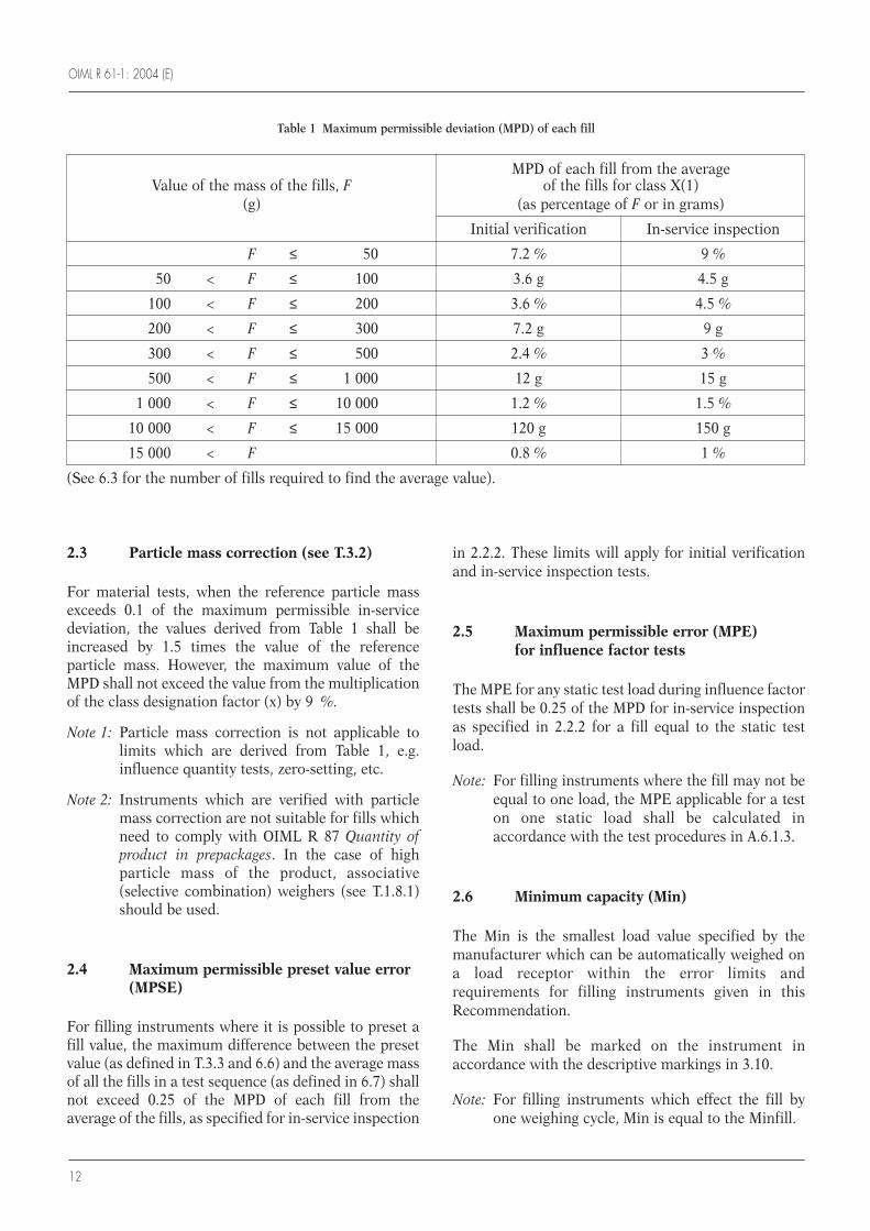
2.2.2 Maximum permissible deviation (MPD)of each fill
The filling instrument shall have a specified accuracyclass X(x), determined at initial verification, for whichthe MPD of each fill from the average of all fills in a testshall be equal to the limits specified in Table 1,multiplied by the class designation factor (x).
The value of (x) shall be 1 × 10k, 2 × 10k or 5 × 10k, kbeing a positive or negative whole number or zero.
Automatic gravimetric filling instruments
OIML R 61-1: 2004 (E)
12
2.3 Particle mass correction (see T.3.2)
For material tests, when the reference particle massexceeds 0.1 of the maximum permissible in-servicedeviation, the values derived from Table 1 shall beincreased by 1.5 times the value of the referenceparticle mass. However, the maximum value of theMPD shall not exceed the value from the multiplicationof the class designation factor (x) by 9 %.
Note 1: Particle mass correction is not applicable tolimits which are derived from Table 1, e.g.influence quantity tests, zero-setting, etc.
Note 2: Instruments which are verified with particlemass correction are not suitable for fills whichneed to comply with OIML R 87 Quantity ofproduct in prepackages. In the case of highparticle mass of the product, associative(selective combination) weighers (see T.1.8.1)should be used.
2.4 Maximum permissible preset value error(MPSE)
For filling instruments where it is possible to preset afill value, the maximum difference between the presetvalue (as defined in T.3.3 and 6.6) and the average massof all the fills in a test sequence (as defined in 6.7) shallnot exceed 0.25 of the MPD of each fill from theaverage of the fills, as specified for in-service inspection
in 2.2.2. These limits will apply for initial verificationand in-service inspection tests.
2.5 Maximum permissible error (MPE)for influence factor tests
The MPE for any static test load during influence factortests shall be 0.25 of the MPD for in-service inspectionas specified in 2.2.2 for a fill equal to the static testload.
Note: For filling instruments where the fill may not beequal to one load, the MPE applicable for a teston one static load shall be calculated inaccordance with the test procedures in A.6.1.3.
2.6 Minimum capacity (Min)
The Min is the smallest load value specified by themanufacturer which can be automatically weighed ona load receptor within the error limits andrequirements for filling instruments given in thisRecommendation.
The Min shall be marked on the instrument inaccordance with the descriptive markings in 3.10.
Note: For filling instruments which effect the fill byone weighing cycle, Min is equal to the Minfill.
Table 1 Maximum permissible deviation (MPD) of each fill
MPD of each fill from the averageValue of the mass of the fills, F of the fills for class X(1)
(g) (as percentage of F or in grams)
Initial verification In-service inspection
F ≤ 50 7.2 % 9 %
50 < F ≤ 100 3.6 g 4.5 g
100 < F ≤ 200 3.6 % 4.5 %
200 < F ≤ 300 7.2 g 9 g
300 < F ≤ 500 2.4 % 3 %
500 < F ≤ 1 000 12 g 15 g
1 000 < F ≤ 10 000 1.2 % 1.5 %
10 000 < F ≤ 15 000 120 g 150 g
15 000 < F 0.8 % 1 %
(See 6.3 for the number of fills required to find the average value).
OIML R 61-1: 2004 (E)
13
2.7 Rated minimum fill (Minfill)
The Minfill is the rated minimum fill from automaticweighing below which the weighing results may besubject to errors outside the limits and requirementsspecified in this Recommendation.
Note: For filling instruments which effect the fill bymore than one weighing cycle Minfill is largerthan the Min.
The Minfill shall be subjected to the followingrequirements:
a) 3.8.2 Capability of zero-setting related toMinfill(*);
b) A.5.2 Warm-up error related to Minfill;
c) A.6.2.2 Temperature effect on no-load indicationrelated to Minfill;
d) A.6.3 Significant fault for disturbance testsrelated to Minfill.
The Minfill value shall be marked on the instrument inaccordance with the descriptive markings in 3.10.
2.8 Influence factors
The permissible effects of influence factors oninstruments under simulated conditions are specifiedfor each case below.
Refer to Annex A for test conditions.
2.8.1 Temperature
2.8.1.1 Prescribed temperature limits
If no particular working temperature is stated in thedescriptive markings of the filling instrument, then theinstrument shall comply with the appropriatemetrological and technical requirements attemperatures from:
– 10 °C to + 40 °C.
The temperature limits shall be marked on theinstrument in accordance with the descriptivemarkings in 3.10.
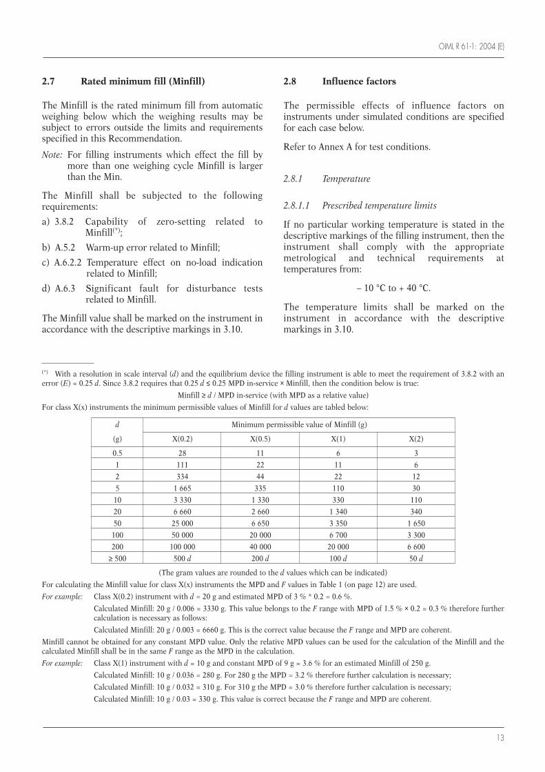
(*) With a resolution in scale interval (d) and the equilibrium device the filling instrument is able to meet the requirement of 3.8.2 with anerror (E) = 0.25 d. Since 3.8.2 requires that 0.25 d ≤ 0.25 MPD in-service × Minfill, then the condition below is true:
Minfill ≥ d / MPD in-service (with MPD as a relative value)
For class X(x) instruments the minimum permissible values of Minfill for d values are tabled below:
(The gram values are rounded to the d values which can be indicated)
For calculating the Minfill value for class X(x) instruments the MPD and F values in Table 1 (on page 12) are used.
For example: Class X(0.2) instrument with d = 20 g and estimated MPD of 3 % * 0.2 = 0.6 %.
Calculated Minfill: 20 g / 0.006 = 3330 g. This value belongs to the F range with MPD of 1.5 % × 0.2 = 0.3 % therefore furthercalculation is necessary as follows:
Calculated Minfill: 20 g / 0.003 = 6660 g. This is the correct value because the F range and MPD are coherent.
Minfill cannot be obtained for any constant MPD value. Only the relative MPD values can be used for the calculation of the Minfill and thecalculated Minfill shall be in the same F range as the MPD in the calculation.
For example: Class X(1) instrument with d = 10 g and constant MPD of 9 g = 3.6 % for an estimated Minfill of 250 g.
Calculated Minfill: 10 g / 0.036 = 280 g. For 280 g the MPD = 3.2 % therefore further calculation is necessary;
Calculated Minfill: 10 g / 0.032 = 310 g. For 310 g the MPD = 3.0 % therefore further calculation is necessary;
Calculated Minfill: 10 g / 0.03 = 330 g. This value is correct because the F range and MPD are coherent.
d Minimum permissible value of Minfill (g)
(g) X(0.2) X(0.5) X(1) X(2)
0.5 28 11 6 3
1 111 22 11 6
2 334 44 22 12
5 1 665 335 110 30
10 3 330 1 330 330 110
20 6 660 2 660 1 340 340
50 25 000 6 650 3 350 1 650
100 50 000 20 000 6 700 3 300
200 100 000 40 000 20 000 6 600
≥ 500 500 d 200 d 100 d 50 d
OIML R 61-1: 2004 (E)
14
2.8.1.2 Special temperature limits
For special applications, the limits of the temperaturerange may differ from those given above, but such arange shall not be less than 30 °C and shall be specifiedin the descriptive markings.
2.8.1.3 Temperature effect on no-load indication
At specified temperatures, the indication at zero shallnot vary by more than the MPE for influence factortests specified in 2.5 for a load equal to the Minfill, fora difference in ambient temperature of 5 °C.
2.8.2 Power supply (AC)
An instrument which is powered by an AC electricitysupply shall comply with the appropriate metrologicaland technical requirements when operated at voltagesfrom – 15 % to + 10 % of the reference voltage values,marked on the instrument.
2.8.3 Power supply (DC)
A filling instrument which is powered by a DC supplyshall comply with the appropriate metrological andtechnical requirements in accordance with 4.2.6 andshall be tested for compliance with the DC poweredinstruments tests according to A.6.4.
2.8.4 Tilting
A filling instrument which is not intended forinstallation in a fixed position and which does not havea level indicator shall comply with the appropriatemetrological and technical requirements when tilted(longitudinally and transversely) by up to 5 %.
Where a level indicator is present it shall enable thefilling instrument to be set to a tilt of 1 % or less.
2.9 Units of measurement
The units of mass are the:
• Metric carat (ct);
• Milligram (mg);
• Gram (g);
• Kilogram (kg); and
• Tonne (t).
3 Technical requirements
3.1 Suitability for use
A filling instrument shall be designed to suit themethod of operation and the products for which it isintended. It shall be of adequately robust constructionso that it maintains its metrological characteristicswhen properly installed and used in an environmentfor which it is intended.
3.2 Security of operation
3.2.1 Fraudulent use
A filling instrument shall have no characteristics likelyto facilitate its fraudulent use.
3.2.2 Accidental breakdown or maladjustment
A filling instrument shall be so constructed that anaccidental breakdown or maladjustment of controlelements likely to disturb the instrument’s correctoperation cannot take place without its effect beingevident.
3.2.3 Security
Means shall be provided for securing components,interfaces, software devices and preset controls of afilling instrument, to which unauthorized access isprohibited or is detected and made evident by an audittrail or similar.
National prescription may specify the security orsealing that is required.
3.2.4 Modifications and identification
Any modifications to the filling instrument or device(s)or software part(s) shall be such that they do not affectits correct operation and metrological characteristics.Modifications shall be identifiable and capable of beingconfirmed at verification.
3.3 Indication of weighing results
3.3.1 Quality of reading
Reading of the results shall be reliable, bright and easyunder conditions of normal use.
OIML R 61-1: 2004 (E)
15
The scales, numbering and printing shall permit thefigures that form the results to be read by simplejuxtaposition.
3.3.2 Form of the indication
Weighing results shall contain the names or symbols ofthe units of mass in which they are expressed.
For any one indication of weight, only one unit of massmay be used.
All indicating, printing and tare weighing devices of afilling instrument shall, within any one weighing range,have the same scale interval for any given load.
Digital indication shall display at least one figurebeginning at the extreme right.
3.3.3 Use of a printer
Printing shall be clear and permanent for the intendeduse. Printed figures shall be at least 2 mm high.
If printing takes place, the name or the symbol of theunit of measurement shall be either to the right of thevalue or above a column of values.
Any printout is for information purposes only and notfor use in any commercial transaction, except presetvalues and number of weighings.
3.3.4 Scale interval (d)
Scale intervals of all indicating devices associated witha weighing unit shall be the same.
3.4 Fill setting device
If fill setting is by means of a scale, it shall be graduatedin units of mass.
If fill setting is by means of weights, they shall be eitherweights in accordance with OIML requirements orpurpose-designed of any nominal value, dis-tinguishable by shape and identified with the fillinginstrument.
3.5 Final feed cut-off device
The final feed cut-off device shall be clearlydifferentiated from any other device. The direction ofmovement corresponding to the sense of the desiredresult shall be shown, where applicable.
For automatic mechanical scales, the final feed cut-offdevice may include an adjustable compensation beamfor the material in flight.
3.6 Feeding device
The feeding device shall be designed to providesufficient and regular flowrate(s).
An adjustable feeding device shall be fitted with anindication of the direction of movement correspondingto the sense of the adjustment of the feed whereapplicable.
3.7 Load receptor
The load receptor, and feed and discharge devices asappropriate, shall be designed to ensure that residualmaterial retained after each discharge is negligible.
A filling instrument using the subtractive weighingprinciple shall be designed to ensure that residualmaterial retained at feed from the discharge gate isnegligible.
The load receptor shall provide access and facilities sothat where necessary test weights or masses up to themaximum capacity can be placed in position, in a safeand secure manner. If these facilities are not apermanent fixture of the instrument, they must be keptin the vicinity of the filling instrument.
Manual discharge of the load receptor shall not bepossible during automatic operation.
3.8 Zero-setting and tare devices
A filling instrument shall be provided with zero-settingand/or tare devices and may be provided withadditional zero-tracking devices. Tare devices (exceptpreset tare devices) may also be used for zeroing. Thedevices may be:
• Nonautomatic (tare balancing and/or preset tare); or
• Semi-automatic; or
• Automatic.
3.8.1 Range of adjustment
The effect of any zero-setting device shall not alter themaximum weighing capacity of the filling instrument.
OIML R 61-1: 2004 (E)
16
The range of adjustment of zero-setting devices shallnot exceed 4 % of the Max of the filling instrument. Therange of adjustment of the initial zero-setting deviceshall not exceed 20 % of the Max of the fillinginstrument.
3.8.2 Accuracy of zero-setting and tare devices
Zero-setting and tare devices (except the preset tarefunction) shall be capable of setting to less than orequal to 0.25 of the MPD for in-service inspection asspecified in 2.2.2 for a fill equal to the Min or Minfillrespectively of the filling instrument.
3.8.3 Control of the zero-setting and tare devices
3.8.3.1 Nonautomatic and semi-automatic devices
Nonautomatic or semi-automatic zero-setting and taredevices must be locked during automatic operation.
The weighing unit shall be in stable equilibrium whenthe zero-setting and tare devices are operating.
3.8.3.2 Automatic devices
An automatic zero-setting device may operate at thestart of automatic operation, as part of every automaticweighing cycle, or after a programmable time interval.A description of the operation of the automatic zero-setting device (e.g. the maximum programmable timeinterval) should be included in the type approvalcertificate.
The automatic zero-setting device shall operatesufficiently often to ensure that zero is maintainedwithin twice the given MPE in 3.8.2.
Where the automatic zero-setting device operates aspart of every automatic weighing cycle, it shall not bepossible to disable this device or to set it to operate attime intervals.
Where the automatic zero-setting device operates aftera programmable time interval, the manufacturer shallspecify the maximum programmable time interval. Themaximum programmable time interval shall not begreater than the value calculated according to themethod in A.5.3.5, or shall be reduced depending onprevailing operating conditions.
The maximum programmable time interval forautomatic zero-setting required above and specified inA.5.3.5 may start again after taring or zero-tracking hastaken place.
The automatic zero-setting device shall generatesuitable information to draw attention to overdue zero-setting.
3.8.4 Zero-tracking device
A zero-tracking device shall operate only when:
• The indication is at zero, or at a negative net valueequivalent to gross zero; and
• The corrections are not more than 0.25 MPD in-service inspection for a fill equal to the Min or Minfillrespectively of the filling instrument.
When zero is indicated after a tare operation, the zero-tracking device may operate within a range of 4 % ofMax of the filling instrument around the actual zerovalue.
Note: Zero-tracking is functionally similar toautomatic zero-setting. The differences areimportant in applying the requirements of 3.8.Automatic zero-setting and zero-tracking aredefined in T.2.4.3 and T.2.4.5. Specifically:
• Automatic zero-setting is activated by an event, suchas part of every automatic weighing cycle or after aprogrammed interval;
• Zero-tracking may operate continuously when theabove conditions are fulfilled and must therefore besubject to a maximum rate of correction of 0.5 MPDin-service inspection to prevent interaction with thenormal weighing process.
3.8.5 Tare device
3.8.5.1 Accuracy and control of tare devices
Accuracy and operation of the tare device shall be asspecified in 3.8.2 and 3.8.3.
3.8.5.2 Subtractive tare device
When the use of a subtractive tare device does notallow the value of the residual weighing range to beknown, a device shall prevent the use of the instrumentabove its maximum capacity or indicate that thiscapacity has been reached.
3.8.5.3 Combined zero-setting and tare devices
If the same key operates the semi-automatic zero-setting device and the semi-automatic tare device, theaccuracy requirements specified in 3.8.2 and in 3.8.4apply at any load.
OIML R 61-1: 2004 (E)
17
3.8.6 Preset tare device
3.8.6.1 Scale interval
The scale interval of a preset tare device shall be equalto or automatically rounded to the scale interval of theinstrument.
3.8.6.2 Modes of operation
A preset tare device may be operated together with oneor more tare devices provided that a preset tareoperation cannot be modified or cancelled as long asany tare device operated after the preset tare operationis still in use.
Preset tare devices may operate automatically only ifthe preset tare value is clearly identified with the loadto be measured (e.g. by bar code identification on thecontainer).
3.9 Equilibrium mechanism
The equilibrium mechanism may be provided withdetachable masses which shall be either weights inaccordance with OIML requirements or purpose-designed masses of any nominal value, distinguishableby shape and identified with the filling instrument.
3.10 Descriptive markings
Filling instruments shall bear the following markings.
3.10.1 Markings shown in full
• Name or identification mark of the manufacturer
• Name or identification mark of the importer (ifapplicable)
• Date of manufacture of the instrument
• Serial number and type designation of theinstrument
• Product(s) designation (i.e. materials that may beweighed)
• Temperature range (if applicable, see 2.8.1) in theform: ....... °C / ....... °C
• Electrical supply voltage in the form: ....... V
• Electrical supply frequency in the form: ....... Hz
• Pneumatic/hydraulic pressure (if applicable) in theform: ....... kPa or bar
• Average number of loads/fill (if applicable) .......
• Maximum fill (if applicable) in the form: Maxfill .......
• Rated minimum fill (if applicable) in the form:Minfill .......
• Maximum rate of operation (if applicable) in theform: ....... loads per minute
3.10.2 Markings shown in code
• Type approval sign
• Indication of the accuracy class in the form: X(x) = …….
• Reference value for the accuracy class in the form:Ref(x) = …….
• Scale interval (if applicable) in the form: d = .......
• Maximum capacity in the form: Max .......
• Minimum capacity (or minimum discharge whereapplicable) in the form: Min .......
• Maximum additive tare in the form: T = + .......
• Maximum subtractive tare in the form: T = – .......
3.10.3 Supplementary markings
Depending upon the particular use of the fillinginstrument, supplementary markings may be requiredon type approval by the metrological authority issuingthe type approval certificate, for example: a fillinginstrument may be verified for different materials forwhich different classes apply or which require differentoperating parameters to maintain limits of error.
Marking shall be such that the materials andalternative class or operating parameters are clearlyassociated with the appropriate material designation.
In the case of subtractive weighers, the minimum loadto be discharged shall be specified.
3.10.4 Presentation of descriptive markings
The descriptive markings shall be indelible and of asize, shape and clarity to enable legibility under normalconditions of use of the filling instrument.
They shall be grouped together in a clearly visible placeon the filling instrument, either on a descriptive plateor on the filling instrument itself.
Where the markings are placed on a descriptive plate,it shall be possible to seal the plate bearing themarkings. Where they are marked on the fillinginstrument itself, it shall not be possible to removethem without destroying them.
OIML R 61-1: 2004 (E)
18
The descriptive markings may be shown on aprogrammable display which is controlled by software.In this case, means shall be provided for any access toreprogramming of the markings to be automaticallyand non-erasably recorded and made evident by anaudit trail, e.g. by traceable access software such as anevent logger providing an information record of thechanges, or an event counter providing a non-resettablecounter of changes.
When a programmable display is used, the descriptiveplate on the instrument shall bear at least the followingmarkings:
• Type and designation of the instrument;
• Name or identification mark of the manufacturer;
• Type approval number;
• Electrical supply voltage;
• Electrical supply frequency; and
• Pneumatic/hydraulic pressure.
3.11 Verification marks
3.11.1 Position
The filling instrument shall have a place for theapplication of verification marks. This place shall:
• Be such that the part on which it is located cannot beremoved from the filling instrument withoutdamaging the marks;
• Allow easy application of the mark without changingthe metrological qualities of the filling instrument;and
• Be visible without the filling instrument or itsprotective covers having to be removed.
3.11.2 Mounting
A filling instrument required to bear verification marksshall have a verification mark support, at the placeprovided for above, which shall ensure the con-servation of the marks. The type and method of sealingshall be determined by national prescription.
3.12 Control instruments
Control instruments may be separate from, or anintegral part of, the filling instrument.
Control instruments may incorporate other devicesincluding software which allows them to determine the
mass of the fill(s). Where other devices and softwareare incorporated into control instruments, they shallcontinue to function correctly and their metrologicalfunctions shall not be influenced.
4 Requirements for electronicinstruments
The type of an electronic instrument is presumed tocomply with the following general requirements if itpasses the examination and tests specified in Annex A,in addition to the applicable requirements of all otherclauses of this Recommendation.
4.1 General requirements
4.1.1 Rated operating conditions
Electronic instruments shall be so designed andmanufactured that they do not exceed the maximumpermissible errors under rated operating conditions.
4.1.2 Disturbances
Electronic instruments shall be so designed andmanufactured that when exposed to disturbances,either:
a) Significant faults do not occur, i.e. the differencebetween the weight indication due to thedisturbance and the indication without thedisturbance (intrinsic error) shall not exceed thevalue of the significant fault specified in T.4.2.6; or
b) Significant faults are detected and acted upon.
Note: A fault equal to or less than the value specified inT.4.2.6 is allowed irrespective of the value of theerror of indication.
4.1.3 Durability
The requirements in 4.1.1, 4.1.2 and 4.2.1 shall be metdurably in accordance with the intended use of theinstrument.
4.1.4 Application
The requirements in 4.1.2 may be applied separately to:
• Each individual cause of significant fault; and/or
• Each part of the electronic instrument.
OIML R 61-1: 2004 (E)
19
The choice of whether:
• Electronic instruments designed to withstanddisturbances (4.1.2 a) above); or
• Electronic instruments designed to detect and act onsignificant faults (4.1.2 b) above)
is applied is left to the manufacturer of the fillinginstrument.
4.2 Functional requirements
4.2.1 Influence factors
An electronic instrument shall comply with theinfluence factors requirements in 2.8 and shall alsocomply with appropriate metrological and technicalrequirements at a relative humidity of 85 % at theupper limit of the temperature range of the instrument.
4.2.2 Indicator display test
If the failure of an indicator display element can causea false weight indication then the instrument may havea display test facility which is automatically initiated atswitch-on of indication, e.g. indication of all therelevant signs of the indicator in their active and non-active states for a period of time sufficient to be easilyobserved by the operator.
4.2.3 Acting upon a significant fault
When a significant fault has been detected, theinstrument shall either be automatically madeinoperative or a visual or audible indication shall beautomatically provided and shall continue until suchtime as the user takes action or the fault disappears.
4.2.4 Warm-up time
During the warm-up time of an electronic instrumentthere shall be no indication or transmission of theresult of weighing, and automatic operation shall beinhibited.
4.2.5 Interfaces
A filling instrument may be equipped with interfaceswhich allow it to be coupled to external equipment andsoftware devices.
An interface comprises all mechanical, electrical andsoftware devices at the communication point betweeninstruments, peripheral and software devices.
When an interface is used, the filling instrument shallcontinue to function correctly and its metrologicalfunctions shall not be influenced by the attachedexternal equipment or software devices or bydisturbances acting on the interface.
Functions that are performed or initiated via aninterface shall meet the relevant requirements andconditions of clause 3.
It shall not be possible to introduce into a fillinginstrument, through an interface, functions, programmodules or data structures intended or suitable to:
• Display unclear data;
• Falsify displayed, processed or stored weighingresults; or
• Unauthorized adjustment of the instrument.
Other interfaces shall be secured in accordance with3.2.3.
4.2.6 Battery power supply (DC)
An instrument that operates from a battery powersupply shall, whenever the voltage drops below themanufacturer’s specified minimum value, eithercontinue to function correctly or automatically be putout of service.
4.3 Examination and tests
Examination and testing of electronic instruments isintended to verify compliance with the applicablerequirements of this Recommendation, particularlythose of clause 4.
4.3.1 Examinations
An electronic instrument shall be examined to obtain ageneral appraisal of its design and construction.
4.3.2 Performance tests
An electronic instrument or electronic device, asappropriate, shall be tested as specified in Annex A todetermine the correct functioning of the instrument.
OIML R 61-1: 2004 (E)
20
Tests are to be carried out on the whole instrumentexcept when the size and/or configuration of theinstrument does not lend itself to testing as a unit. Insuch cases the electronic devices shall be tested, wherepossible as a simulated instrument including allelectronic elements of a system which can affect theweighing result. In addition, an examination shall becarried out on the fully operational instrument.
Susceptibility to other equipment that would resultfrom the use of electronic interfaces shall be simulatedin the tests.
4.3.3 Span stability
When an electronic instrument is subjected to the spanstability test specified in A.7, the absolute value of thedifference between the errors obtained for any twomeasurements shall not exceed half the MPE forinfluence factor tests for a near maximum capacityload.
5 Metrological controls
5.1 General
The metrological controls of instruments shall, inagreement with national legislation, consist of:• Type approval;• Initial verification;• Subsequent verification; and• In-service inspection.
Tests should be applied uniformly by the metrologicalauthority and should form a uniform program.Guidance for the conduct of pattern approval andinitial verification is provided in OIML InternationalDocuments D 19 Pattern evaluation and patternapproval and D 20 Initial and subsequent verification ofmeasuring instruments and processes respectively.
For the purposes of testing, the metrological authoritymay require the applicant to provide the product (i.e.the material to be weighed), the handling equipment,the control instrument (as defined in 3.12 and A.3.6)and the personnel to perform the tests.
5.2 Type approval
5.2.1 Documentation
The application for type approval shall includedocumentation comprising:
• The metrological characteristics of the instrument;
• A set of specifications for the instrument;
• A functional description of the components anddevices;
• Drawings, diagrams and general software informa-tion (if applicable), explaining the construction andoperation, including interlocks; and
• Any document or other evidence that the design andconstruction of the instrument complies with therequirements of the present Recommendation.
Note: Adherence to requirements for which no test isavailable, such as software-based operations,may be demonstrated by a specific declaration ofthe manufacturer (e.g. for interfaces as specifiedin 4.2.5, and for password protected access toprevent unauthorized access in accordance with3.2.3).
5.2.2 General requirements
Type evaluation shall be carried out on one or more(and normally not more than three) instruments thatrepresent the definitive type. At least one of theinstruments shall be submitted in a form suitable forsimulation testing in a laboratory and shall include thewhole of the electronics which affect the weighingresult except in the case of an associative weigher,where only one representative weighing unit may beincluded.
The evaluation shall consist of the tests specified in5.2.3.
The MPE for static tests shall be apportioned inaccordance with 5.2.3.3 to parts of the filling instru-ment that are tested separately.
5.2.3 Type evaluation
The documents submitted shall be examined and testscarried out to verify that the instrument complies with:
• The requirements for static tests specified in clause 2;
• The technical requirements in clause 3; and
• The requirements in clause 4 for electronic instru-ments, where applicable.
The metrological authority shall:
• Conduct the tests in a manner which prevents anunnecessary commitment of resources; and
• Permit the results of these tests to be assessed forinitial verification.
OIML R 61-1: 2004 (E)
21
Note: The metrological authority is advised to accept,with the consent of the applicant, equivalent testdata obtained from other metrologicalauthorities without repeating the tests.
5.2.3.1 Operational tests for type evaluation
Tests for type evaluation shall be conducted:
• In accordance with the appropriate parts of clause 3;
• Under the normal conditions of use for which theinstrument is intended; and
• In accordance with the material test methods givenin clause 6, using material that is representative of aproduct for which the filling instrument is designedto assess compliance with the technical requirementsof clause 3.
5.2.3.2 Influence factor tests
Influence factors shall be applied to the instrument orsimulator during simulation tests in a manner that willreveal a corruption of the weighing result of anyweighing process to which the instrument could beapplied, in accordance with:
• Subclause 2.8 for all instruments; and
• Clause 4 for electronic instruments.
5.2.3.3 Apportioning of errors
Where parts of a filling instrument are examinedseparately in the process of type approval, the followingrequirements apply:
The error limits applicable to a part which is examinedseparately are equal to a fraction Pi of the maximumpermissible errors or the allowed variations of theindication of the complete instrument. The fractionsfor any part have to be taken for the same accuracyclass as for the complete instrument incorporating thepart.
The fractions Pi shall satisfy the following equation:(P1
2 + P22 + P3
2 + ....) ≤ 1
The fraction Pi shall be chosen by the manufacturer ofthe part, and shall be verified by an appropriate test.However, the fraction shall not exceed 0.8 and shall notbe less than 0.3, when more than one part contributesto the effect in question.
If the metrological characteristics of the load cell orother major component have been evaluated inaccordance with the requirements of any OIMLInternational Recommendation (e.g. R 60 for loadcells), then that evaluation shall be used to aid in thetype evaluation if so requested by the applicant.
Note: As the requirements of this subclause only applyto the instrument submitted for type evaluationand not to those subsequently submitted forverification, the means by which it will bepossible to determine whether the appropriateMPE or maximum allowable variation has beenexceeded will be decided mutually between themetrological authority and the applicant. Themeans may be for example:• The provision or adaptation of the indicating
device to give the required resolution orappropriate increment or scale interval;
• The use of change point weights; or• Any other means mutually agreed upon.
5.2.4 Place of testing for type approval
Instruments submitted for type approval may be testedeither:• On the premises of the metrological authority to
which the application has been submitted; or• In any other suitable place agreed between the
metrological authority concerned and the applicant.
5.2.5 Type approval certificate and determination of classes (2.2.1 and A.5)
The type approval certificate shall state the referencevalue for the accuracy class Ref(x) as determined by thestatic tests in A.5, and shall state that the actual class(equal to or higher than the reference value) shall bedetermined by compliance with the metrologicalrequirements on initial verification.
5.3 Initial verification
5.3.1 General requirements
Filling instruments shall be examined for conformitywith the approved type (where applicable) and shall betested for compliance with clause 2 (excluding 2.2.1and 2.5) for the intended products and correspondingaccuracy classes and when operated under normalconditions of use.
Tests shall be carried out by the metrological authority,in-situ, with the filling instrument fully assembled andfixed in the position in which it is intended to be used.
The installation of a filling instrument shall be sodesigned that an automatic weighing operation will bethe same, whether for the purposes of testing or for usein a transaction.
OIML R 61-1: 2004 (E)
22
5.3.2 Material tests for initial verification
In-situ material tests shall be done:• In accordance with the descriptive markings given in
3.10;• Under the normal conditions and with the products
for which the filling instrument is intended; and• In accordance with the test method in clause 6 and
the material tests procedure given in A.8.2.
Accuracy requirements shall be applied in accordancewith the appropriate parts of clause 2.
5.3.3 Conduct of the tests
The metrological authority:• Shall conduct the tests in a manner which prevents
an unnecessary commitment of resources; and• May, where appropriate and to avoid duplicating
tests previously performed on the instrument fortype evaluation under 5.2, use the test results fromtype evaluation for initial verification.
5.3.4 Determination of accuracy class X(x)
For class X(x) filling instruments the metrologicalauthority shall:• Determine the accuracy class for the materials used
in the tests in accordance with 5.2.5 by reference tothe material test results from A.8 and the limits oferror specified in 2.2.2 and 2.4 for initial verification;and
• Verify that accuracy classes marked in accordancewith descriptive markings in 3.10 are equal to orgreater than the accuracy classes determined asabove.
5.4 Subsequent verification
Subsequent verification shall be carried out inaccordance with the same provisions as in 5.3 forinitial verification.
5.5 In-service inspection
In-service inspection shall be as specified in:• 5.3.1 general requirements for initial verification;
and• 5.3.2 materials tests for initial verification.
The MPEs shall be as specified in 2.2.2 for in-serviceinspection.
6 Test methods
6.1 Determination of the mass of individualfills
The mass of individual fills is determined using eitherthe separate verification method given in 6.5.1 or theintegral verification method given in 6.5.2.
6.2 Conduct of material tests
6.2.1 Values of the mass of the fills
a) The tests shall be carried out on fills using loads at,or near to, the Max and also at, or near to, theMinfill of the filling instrument.
b) Cumulative weighers shall be tested as in a) with themaximum practical number of loads per fill andalso with the minimum number of loads per fill, andassociative weighers as in a) with the average (oroptimum) number of loads per fill (see T.3.10).
c) If the Minfill is less than one third of the Maxfillthen tests shall also be carried out near the center ofthe load weighing range preferably at a value closeto, but not above, 100 g, 300 g, 1 000 g or 15 000 g,as appropriate.
6.2.2 Types of test loads
For type evaluation, the materials used for test loadsshall be as specified in 5.2.3.1 and for initialverification and in-service inspection, they shall be asspecified in 5.3.2.
6.2.3 Condition of tests
All tests shall be conducted with any adjustableparameter critical to metrological integrity, e.g. finalfeed time or rate, set to the most onerous conditionallowed by the manufacturer’s printed instructions andincorporated in the descriptive markings.
Prior to the start of a new test, the filling instrumentshall be operated for a time period under normaloperating conditions to enable stability, i.e. until all theprincipal parts, devices and parameters such as warm-up, temperature, indications, etc., critical tometrological integrity have stabilized according to themanufacturer’s printed instructions. During thisstabilization period the fills shall not be included in thetest.
OIML R 61-1: 2004 (E)
23
Any correction device, e.g. in flight correction and/orautomatic zero-setting fitted to an instrument shall beoperated during the tests according to themanufacturer’s printed instructions.
The initial fills after the change between Max and Minshall be included in the test unless the instrument bearsa clear warning to discard a stated number of fills aftera change to the instrument settings.
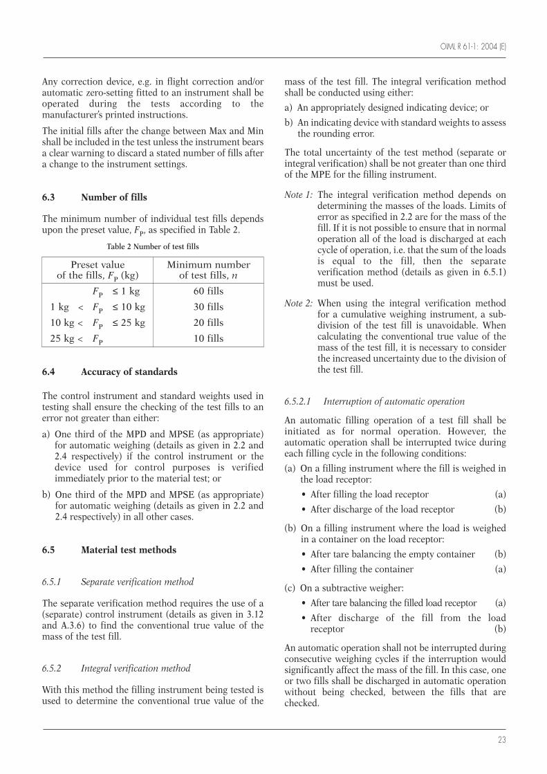
6.3 Number of fills
The minimum number of individual test fills dependsupon the preset value, FP, as specified in Table 2.
Table 2 Number of test fills
6.4 Accuracy of standards
The control instrument and standard weights used intesting shall ensure the checking of the test fills to anerror not greater than either:
a) One third of the MPD and MPSE (as appropriate)for automatic weighing (details as given in 2.2 and2.4 respectively) if the control instrument or thedevice used for control purposes is verifiedimmediately prior to the material test; or
b) One third of the MPD and MPSE (as appropriate)for automatic weighing (details as given in 2.2 and2.4 respectively) in all other cases.
6.5 Material test methods
6.5.1 Separate verification method
The separate verification method requires the use of a(separate) control instrument (details as given in 3.12and A.3.6) to find the conventional true value of themass of the test fill.
6.5.2 Integral verification method
With this method the filling instrument being tested isused to determine the conventional true value of the
mass of the test fill. The integral verification methodshall be conducted using either:
a) An appropriately designed indicating device; or
b) An indicating device with standard weights to assessthe rounding error.
The total uncertainty of the test method (separate orintegral verification) shall be not greater than one thirdof the MPE for the filling instrument.
Note 1: The integral verification method depends ondetermining the masses of the loads. Limits oferror as specified in 2.2 are for the mass of thefill. If it is not possible to ensure that in normaloperation all of the load is discharged at eachcycle of operation, i.e. that the sum of the loadsis equal to the fill, then the separateverification method (details as given in 6.5.1)must be used.
Note 2: When using the integral verification methodfor a cumulative weighing instrument, a sub-division of the test fill is unavoidable. Whencalculating the conventional true value of themass of the test fill, it is necessary to considerthe increased uncertainty due to the division ofthe test fill.
6.5.2.1 Interruption of automatic operation
An automatic filling operation of a test fill shall beinitiated as for normal operation. However, theautomatic operation shall be interrupted twice duringeach filling cycle in the following conditions:
(a) On a filling instrument where the fill is weighed inthe load receptor:
• After filling the load receptor (a)
• After discharge of the load receptor (b)
(b) On a filling instrument where the load is weighedin a container on the load receptor:
• After tare balancing the empty container (b)
• After filling the container (a)
(c) On a subtractive weigher:
• After tare balancing the filled load receptor (a)
• After discharge of the fill from the load receptor (b)
An automatic operation shall not be interrupted duringconsecutive weighing cycles if the interruption wouldsignificantly affect the mass of the fill. In this case, oneor two fills shall be discharged in automatic operationwithout being checked, between the fills that arechecked.
Preset value Minimum numberof the fills, FP (kg) of test fills, n
FP ≤ 1 kg 60 fills
1 kg < FP ≤ 10 kg 30 fills
10 kg < FP ≤ 25 kg 20 fills
25 kg < FP 10 fills
OIML R 61-1: 2004 (E)
24
a) Pre-discharge (full) interrupt
The automatic operation shall be interruptedimmediately after the feed of material has ceased andthe load receptor(s), or the container on the loadreceptor has been filled, or on a subtractive weigher thefilled load receptor has been tare balanced.
When the load receptor(s) has (have) stabilized, the netweight of the fill indicated or determined by balancingwith standard weights shall be recorded and theinstrument switched back to automatic operation.
b) Post-discharge (empty) interrupt
The automatic operation shall be interrupted after theload(s) has (have) been discharged, or a new containerhas been placed on the load receptor and its weight hasbeen tare balanced, and the load receptor(s) is (are)ready to receive a further load. When the loadreceptor(s) has (have) stabilized, the empty loadreceptor weight indicated or determined by balancingwith standard weights shall be recorded and theinstrument switched back to automatic operation.
6.6 Preset value
The indicated preset value of the fill shall be noted,where applicable.
6.7 Mass and average value of the test fills
The test fill shall be weighed on a control instrumentand the result shall be considered as being theconventional true value of the test fill. The averagevalue of all the fills in the test shall be calculated andnoted.
6.8 Deviation for automatic weighing
The deviation for automatic weighing used todetermine compliance of each fill with the maximumpermissible deviation for automatic weighing(specified in 2.2.2) shall be the difference between theconventional true value of the mass of the test fill (asdefined in 6.7) and the average value of all the fills inthe test.
6.9 Preset value error for automatic weighing
The preset value error for automatic weighing used todetermine compliance with 2.4 shall be the differencebetween the average value of the conventional truevalue of the mass of the test fills (as defined in 6.7) andthe preset value of the fills.
OIML R 61-1: 2004 (E)
25
Meaning of symbols:
I = IndicationIn = nth indicationL = Load∆L = Additional load to next changeover pointP = I + 1/2 d – ∆L = Indication prior to rounding
(digital indication)E = I – L or P – L = ErrorMPE = Maximum permissible errorMPD = Maximum permissible deviation of each fill
from the average value of all the fillsEUT = Equipment under testse = Preset value error (setting error)MPSE = Maximum permissible setting errorF = Conventional true value of the mass of the
fillFP = Preset value of fillmdmax = Maximum of the absolute values of the
actual deviations of the fill from the averagevalue of all the fills
A.1 Examination for type approval
A.1.1 Documentation
Review the documentation that is submitted todetermine if it is adequate and correct. For typeapproval the documentation shall be as specified in5.2.1.
A.1.2 Compare construction withdocumentation
Examine the various devices of the instrument toensure compliance with the documentation inaccordance with 4.3.
A.1.3 Metrological requirements
Note the metrological characteristics using thechecklist in the Test Report Format in R 61-2.
A.1.4 Technical requirements
Examine the instrument for conformity with thetechnical requirements of clause 3, using the checklistgiven in the Test Report Format in R 61-2.
A.1.5 Functional requirements
Examine the instrument for conformity with functionalrequirements according to details given in 4.2 and 4.3respectively, using the checklist given in the Test ReportFormat in R 61-2.
A.2 Examination for initial verification
A.2.1 Compare constructionwith documentation
Examine the instrument for conformity with theapproved type in accordance with the requirements in5.3.1.
A.2.2 Descriptive markings
Check the descriptive markings in accordance with3.10 and use the checklist given in R 61-2.
A.3 General test requirements
A.3.1 Power supply (in accordance with 2.8.2)
Power up the equipment under test (EUT) for a timeperiod equal to or greater than the warm-up timespecified by the manufacturer and maintain the EUTenergized for the duration of each test.
A.3.2 Zero-setting (in accordance with 3.8)
Using the manual or semi-automatic zero-settingfacility, adjust the EUT as closely as practicable to zero
Annex ATesting procedures for automatic gravimetric filling instruments
(Mandatory)
OIML R 61-1: 2004 (E)
26
prior to each test, and do not readjust it at any timeduring the test, except to reset if a significant fault hasbeen indicated.
Status of automatic zero facilities shall be as specifiedfor each test.
A.3.3 Temperature (in accordance with 2.8.1)
The tests shall be performed at a steady ambienttemperature, usually normal ambient temperatureunless otherwise specified. The temperature is deemedto be steady when the difference between the extremetemperatures noted during the test does not exceedone-fifth of the temperature range of the instrumentwithout being greater than 5 °C, and the rate of changedoes not exceed 5 °C per hour.
The handling of the instrument shall not result incondensation of water on the instrument.
A.3.4 Recovery
After each test the filling instrument shall be allowed torecover sufficiently before the next test.
A.3.5 Pre-loading
Before each weighing test the filling instrument shallbe pre-loaded to Max, except for the tests in A.5.2 andA.6.2.2.
A.3.6 Control instruments (T.1.9 and 3.12)
A.3.6.1 Accuracy of test system (in accordancewith 6.4)
The control instrument and standard weights used intesting shall ensure the determination of the weight oftest loads and fills to an error not greater than one thirdof the MPE of the filling instrument in accordance with6.4 a) or b) for material tests.
Note: Accuracy requirements for the test systemdepend on the limits of error, which depend onthe accuracy class. However, the class isdetermined from the results of the tests. It istherefore necessary that the metrologicalauthority responsible for testing should beinformed of the best accuracy class that may beachieved, prior to commencement of testing.
A.3.6.2 Use of standard weights to assessrounding error of indication
A.3.6.2.1 General method to assess error ofindication prior to rounding
For instruments with digital indication having a scaleinterval d, changeover points may be used tointerpolate between scale intervals, i.e. to determinethe indication of the instrument, prior to rounding, asfollows.
At a certain load, L, the indicated value, I, is noted.Additional weights of for example 0.1 d are successivelyadded until the indication of the instrument isincreased unambiguously by one scale interval (I + d).The additional load ∆L added to the load receptor givesthe indication, P, prior to rounding by using thefollowing formula:
P = I + 0.5 d – ∆L
The error prior to rounding is:E = P – L = I + 0.5 d – ∆L – L
Example: A weighing instrument with a scale interval,d, of 5 g is loaded with 1 kg and thereby indicates1 000 g. After adding successive weights of 0.5 g, theindication changes from 1 000 g to 1 005 g at anadditional load of 1.5 g. Inserted in the above formulathese observations give:
P = (1 000 + 2.5 – 1.5) g = 1 001 g
Thus the true indication prior to rounding is 1 001 g,and the error of indication prior to rounding is:
E = (1 001 – 1 000) g = + 1 g
A.3.6.2.2 Correction for error at zero
Evaluate the error at zero load, E0, by the method ofA.3.6.2.1.
Evaluate the error at load L, E, by the method ofA.3.6.2.1.
The corrected error prior to rounding, Ec, is:Ec = E – E0
Example: If, for the example in A.3.6.2.1, the errorcalculated at zero load was E0 = + 0.5 g, thecorrected error is:
Ec = + 1 – (+ 0.5) = + 0.5
A.4 Test program
A.4.1 Type evaluation (in accordance with 5.2.2 and 5.2.3)
The following tests shall normally be applied for typeevaluation:
OIML R 61-1: 2004 (E)
27
• Examination for type approval in A.1;
• Static tests in A.5;
• Influence factor and disturbance tests given in A.6;
• Span stability test in A.7; and
• Material tests in A.8.1.
A.4.2 Nonautomatic weighing instruments(in accordance with 1.1)
For instruments in which the weighing function isprovided by a nonautomatic weighing instrument thathas been approved in respect of conformity with R 76,the tests specified in A.4.1 may be omitted whereequivalent test results specified in R 76 prove con-formity with the relevant parts of R 61. Use of R 76 testresults shall be recorded in the test report checklist andsummary in R 61-2.
A.4.3 Initial verification (in accordance with 5.3)
The following tests shall normally be applied for initialverification:
• Examination for initial verification in A.2; and
• Material tests at initial verification in A.8.2.
The static weighing test method (as detailed in A.5.4)may also be used if necessary to verify the indicator forthe integral verification method of material tests.
A.5 Static tests (type approval stage)
A.5.1 General (in accordance with 5.2.2 and 5.2.3.2)
Electronic instruments or instrument simulators arerequired to have a load indicator, or an interfaceallowing access to a quantity that can be calibrated toprovide an indication of load so that the effect ofinfluence quantities may be tested and the referenceaccuracy class determined. This facility also enablestesting of warm-up time and zero-setting and taredevices where applicable. The static weighing tests arenormally done as part of influence quantity testing.
Limits for warm-up time tests and for accuracy of zero-and tare-setting tests are derived from 2.2, and aretherefore dependent on the reference accuracy classRef(x). Therefore the results of these tests must beevaluated after Ref(x) has been determined as specifiedin 5.2.5.
A.5.2 Warm-up time (in accordance with 4.2.4)
This test is to verify that metrological performance ismaintained in the period immediately after switch-on.The method is to check that automatic operation isinhibited until a stable indication is obtained and toverify that the zero variation and the errors at Maxcomply with the specified requirements during the first30 minutes of operation. If the zero is set as part of thenormal automatic weighing cycle then this functionshall be enabled or simulated as part of the test.
Other test methods which verify that metrologicalperformance is maintained during the first 30 minutesof operation may be used.
1) Disconnect the instrument from the power supplyfor a period of at least 8 hours prior to the test.
2) Reconnect the instrument and switch on whileobserving the load indicator.
3) Check that it is not possible to initiate automaticweighing until the indicator has stabilized.
4) As soon as the indication has stabilized, set theinstrument to zero if this is not done automatically.
5) Determine the error at zero by the method ofA.3.4.2.1, and specify this error as E0I (error ofinitial zero-setting) at first and as E0 (zero-settingerror) when repeating this step.
6) From 5) verify that E0I is not greater than the MPEspecified in 3.8.2.
7) Apply a static load close to Max. Determine theerror by the method of A.3.4.2.1 and A.3.4.2.2.
8) Repeat steps 5) and 6) after 5, 15 and 30 minutes.
9) From 7) and 8) verify that:• The error (corrected for zero error) for a static
load close to Max is not greater than the MPEspecified in 2.5;
• After each time interval the zero-variation error(E0 – E0I) is not greater than the MPE specified in3.8.2.
A.5.3 Zero-setting and tare devices (in accordance with 3.8)
A.5.3.1 General
Unless it is clear that zero and tare functions areperformed by the same process, then both functionsshall be tested separately.
Zero-setting and taring may be by more than onemode, for example:• Nonautomatic or semi-automatic;• Automatic at switch-on;
OIML R 61-1: 2004 (E)
28
• Automatic at start of automatic operation;• Automatic at programmable time intervals; or• Automatic as part of weighing cycle.
It is normally only necessary to test the accuracy ofzero-setting and taring in one mode if it is clear that thesame process is used for each mode. If zero-setting ortaring is set as part of the automatic weighing cyclethen this mode shall be tested. To test automatic zero-setting or taring it is necessary to allow the fillinginstrument to operate through the appropriate part ofthe automatic cycle and then to halt the instrumentbefore testing.
The range and accuracy of zero-setting shall be testedby applying loads as specified below in nonautomatic(static) operation to the load receptor after theinstrument is halted.
A.5.3.2 Range of zero-setting
A.5.3.2.1 Initial zero-setting
a) Positive range
With the load receptor empty, set the instrument tozero. Place a test load on the load receptor and set theinstrument to zero again. Continue this process until itdoes not reset to zero. The maximum load that can bere-zeroed is the positive portion of the initial zero-setting range.
b) Negative range
1) Remove any load from the load receptor and set theinstrument to zero. Then, if possible, remove anynon-essential components of the load receptor. If, atthis point, the instrument can be reset to zero withthe zero-setting device, the mass of the non-essential components is used as the negative portionof the initial zero-setting range.
2) If the instrument cannot be reset to zero with thenon-essential components removed, add loads toany live part of the scale until the instrumentindicates zero again.
3) Then remove the loads and, after each load isremoved, use the zero-setting device. The maximumload that can be removed while the instrument canstill be reset to zero by the zero-setting device is thenegative portion of the initial zero-setting range.
4) The initial zero-setting range is the sum of thepositive and negative portions.
5) Alternatively, if it is not possible to test the negativerange of initial zero-setting by removing parts of theinstrument, the instrument may be temporarily re-calibrated with a test load applied before step 3)above. (The test load applied for the temporary re-
calibration should be greater than the permissiblenegative portion of the initial zero-setting rangewhich can be calculated from the result of thepositive range test).
6) If it is not possible to test the negative portion of theinitial zero-setting range by these methods, thenonly the positive part of the zero-setting range needto be considered.
7) Reassemble or recalibrate the instrument fornormal use after the above tests.
A.5.3.2.2 Automatic zero-setting range
Remove the non-essential parts of the load receptor orre-calibrate the instrument as described in A.5.3.2.1and place weights on the live part of the scale until itindicates zero.
Remove weights in small amounts and after eachweight is removed allow the instrument to operatethrough the appropriate part of the automatic cycle soas to see if the instrument is reset to zero automatically.
The maximum load that can be removed so theinstrument can still be reset to zero is the zero-settingrange.
A.5.3.3 Accuracy of zero-setting
1) When the load receptor is empty, zero the fillinginstrument in a mode as determined by A.5.3.1.
2) Add load(s) to the load receptor to determine theadditional load at which the indication changesfrom zero to one scale interval above zero.
3) Calculate the error at zero according to the methoddescribed in A.3.6.2.1.
4) Verify that the zero-setting error is within the limitspecified in 3.8.2.
A.5.3.4 Accuracy of taring
The accuracy of the tare device shall be tested at themaximum tare as specified by the manufacturer.
1) Place the maximum tare load on the load receptor,then operate the tare function key immediately in amode as determined by A.5.3.1 to enable theequilibrium device to release the tare function.
2) Add load(s) to the load receptor to determine theadditional load at which the indication changesfrom zero to one scale interval above zero.
3) Calculate the error according to the methoddescribed in A.3.6.2.1.
4) Verify that the zero-setting error is within the limitspecified in 3.8.2.
OIML R 61-1: 2004 (E)
29
A.5.3.5 Frequency of automatic zero-settingand taring
This test does not need to be performed for fillinginstruments that have automatic zero-setting as part ofevery automatic weighing cycle.
If the zero-setting device is not part of the automaticweighing cycle but operates with a programmable timeinterval, the value for maximum permissible timeinterval for automatic zero-setting shall be determinedas follows:
a) The maximum allowable rate of change of a steadyambient temperature is 5 °C per hour as specified inA.3.3.
b) Subclause 3.8.2 requires that maximum zero-settingerror:
(Ezsemax) ≤ 0.25 MPD in-service × Minfill × Ref(x) (1)
c) For the maximum zero-checking error, 3.8.3.2requires that:
(Ezcmax) ≤ 0.5 MPD in-service × Minfill × Ref(x) (2)
so the maximum zero-variation (∆zmax) is:
(Ezcmax – Ezsemax) = 0.25 MPD in-service × Minfill × Ref(x)(3)
d) A.6.2.2 requires that the maximum zero-variation(∆zmax) per 5 °C is less than or equal to 0.25 MPD in-service:
∆zmax per 5 °C ≤ 0.25 MPD in-service × Minfill × Ref(x)(4)
e) Substituting the 5 °C per hour steady ambienttemperature from a) above for ∆zmax per 5 °C inequation (4) gives:
∆zmax per hour ≤ 0.25 MPD in-service × Minfill × Ref(x)(5)
Since equations (4) and (5) are identical, a fillinginstrument which needs the maximum allowablevariation given in A.6.2.2 has a maximumprogrammable time interval of automatic zero-settingor taring of 1 hour. If the filling instrument needs lessor more of the maximum zero-variation given inA.6.2.2, the maximum programmable time interval ofautomatic zero-setting or taring may be increased ordecreased proportionally.
In exceptional situations the effects of external factorssuch as operating temperatures, environmentalconditions, stickiness of the product being handled,etc, may determine the maximum programmable timeinterval of automatic zero-setting or taring, which shallbe no greater than 2 hours.
A.5.4 Static weighing test method for typeevaluation (in accordance with 5.2.3)
Apply test loads from zero up to and including Max,and similarly remove the test loads back to zero. Thetest loads selected shall include values close to Max andMin and other critical loads as specified in 6.2.1 c),subject to the requirements of this Annex.
Determine the error at each test load, using thestandard weights assessment procedure of A.3.6.2, ifnecessary, to obtain the accuracy of the test system asspecified in A.3.6.1.
It should be noted that when loading or unloading, theload shall be progressively increased or progressivelydecreased.
A.5.5 Determination of reference accuracyclass, Ref(x) (in accordance with 5.2.5)
The static weighing tests during application ofinfluence factors (as appropriate) shall be used at typeapproval stage to establish the reference value foraccuracy class, i.e. Ref(x), as follows:
1) Perform static weighing tests for influence factorsand loads as specified in this Annex.
2) Determine the MPE for influence factor tests forclass X(1), MPE(1) for each load as follows:
MPE(1) = 0.25 MPD(1) × (Pi, if applicable) in-serviceinspection for the fill value equal to the load.
For example, with a load of 10 kg, the MPE forinfluence factor tests as specified in 2.5 will becalculated thus:
MPE(1) = Pi × (0.25 × 1.5 % × 10 000 g)
where: Pi (as specified in 5.2.3.3) is a fraction of theMPE applied to a part of the fillinginstrument which is examined separately;
MPE(1) is the error limit specified in 2.2 andgiven in Table 1 for mass of fill.
3) Calculate [.Error. / MPE(1)] for each load
where: Error is the corrected error calculated atzero load, in units of mass, as specified inA.3.6.2.2.
4) From 3) determine the maximum value of [.Error. /MPE(1)] for all the influence factor tests,
i.e. [.Error. / MPE(1)]Max for all influence factor tests
5) Determine Ref(x) from [.Error. / MPE(1)]Max suchthat:
Ref(x) ≥ [.Error. / MPE(1)]Max andRef(x) = 1 × 10k, 2 × 10k, or 5 × 10k,
OIML R 61-1: 2004 (E)
30
the index k being a positive or negative whole numberor zero. Values for significant fault shall then becalculated from the MPD for the reference class.
A.6 Influence factorand disturbance tests
A.6.1 Test conditions
A.6.1.1 General requirements
Prior to a test, the error at zero shall be assessed andcorrected by the methods given in A.3.6.2 and inA.3.6.2.2.
Influence factor and disturbance tests specified in 4.1.2and 4.2.1 are intended to verify that electronicinstruments can perform and function as intended inthe environment and under the conditions specified.Each test indicates, where appropriate, the referencecondition under which the intrinsic error isdetermined.
It is generally not possible to apply the influencefactors or disturbances to a filling instrument whichare processing material automatically. The instrumentshall therefore be subjected to the influence factors ordisturbances under static conditions or simulatedoperation as defined herein. The permissible effects ofthe influence factors or disturbances, under theseconditions, are specified for each case.
When the effect of one influence factor is beingevaluated, all other factors are to be held relativelyconstant, at a value close to normal. After each test thefilling instrument shall be allowed to recoversufficiently before the following test.
Where parts of the filling instrument are examinedseparately, errors shall be apportioned in accordancewith details given in 5.2.3.3.
The operational status of the filling instrument orsimulator shall be recorded for each test.
When the filling instrument is connected in other thana normal configuration, the procedure shall bemutually agreed on by the approving authority and theapplicant.
A.6.1.2 Simulator requirements
A.6.1.2.1 General
The simulator for influence factor and disturbancetests should include all electronic devices of theweighing system.
A.6.1.2.2 Load cell
The simulator should also include the load cell and ameans to apply standard test loads. Where this is notpossible, e.g. for high capacity instruments, then a loadcell simulator may be used or alternatively the load cellinterface may be modified to incorporate a scalingfactor to give the design output for a small test load.
Repeatability and stability of a load cell simulatorshould make it possible to determine the performanceof the instrument with at least the same accuracy aswhen the instrument is tested with weights.
A.6.1.2.3 Interfaces (details as given in 4.2.5)
Susceptibility that would result from the use ofelectronic interfaces to other equipment shall besimulated in the tests. For this purpose it is sufficientto connect 3 m of interface cable terminated tosimulate the interface impedance of the otherequipment.
A.6.1.2.4 Documentation
Simulators shall be defined in terms of hardware andfunctionality by reference to the instrument under test,and by any other documentation necessary to ensurereproducible test conditions.
This information shall be attached to, or be traceablefrom the test report.
A.6.1.3 Test limits for multi-load instruments
For a filling instrument where the fill may consist ofmore than one load, the value of a significant fault andthe limit of error for influence factor tests must bedetermined by the metrological authority ormanufacturer after considering the design of theinstrument and the method of test, such that the effecton the fill is not greater than the significant fault valuespecified in T.4.2.6 and the MPE specified in 2.5.
A.6.1.3.1 Significant fault for multi-loadinstruments
The following examples show how to determine thevalue of a significant fault on selective combinationweighers and cumulative weighers when testing.
• Significant fault for selective combination weighers:
A fault greater than 0.25 MPD of each fill (as given inTable 1) for in-service inspection divided by the squareroot of the average (or optimum) number of loads in afill, for a fill equal to the Min multiplied by the average(or optimum) number of loads in a fill.
Example: For a class X(1) filling instrument withMin = 200 g designed for an average of8 loads per fill, fill = 1 600 g, the MPD of each
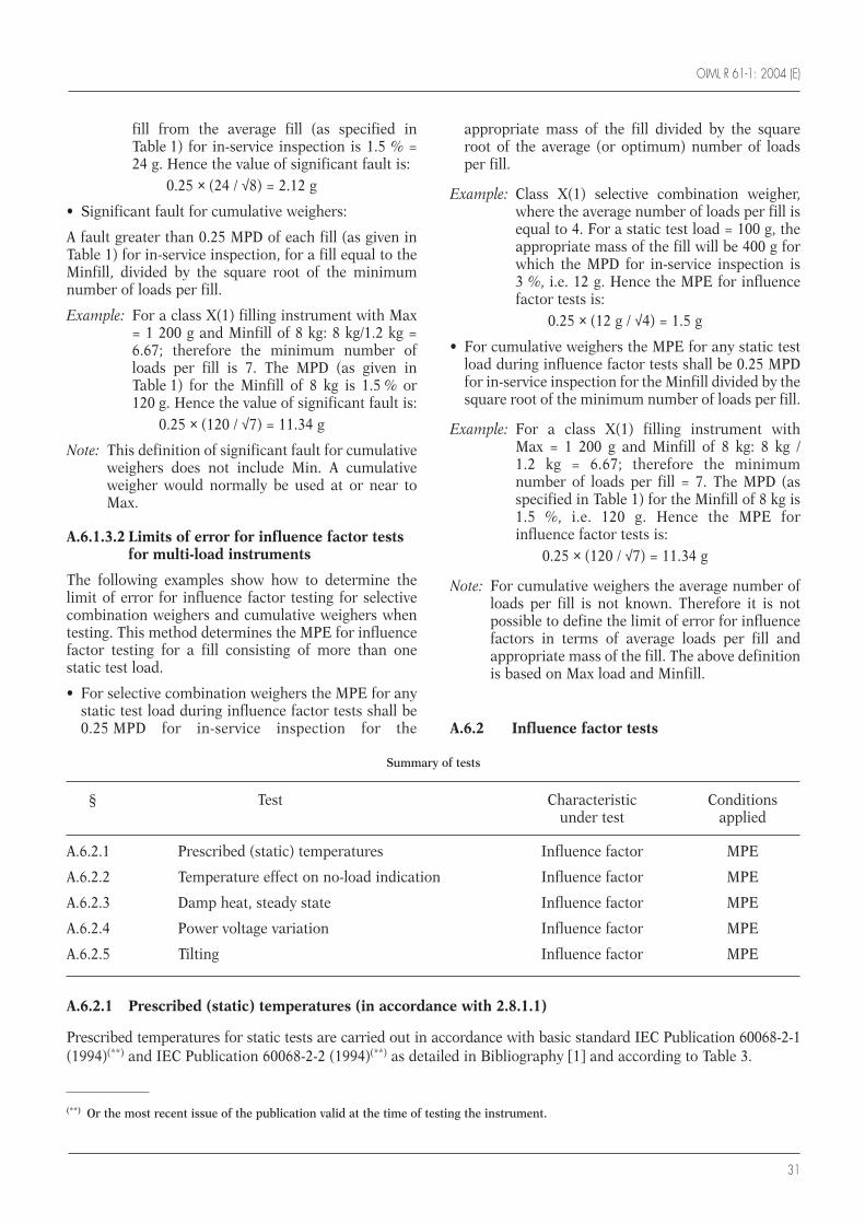
OIML R 61-1: 2004 (E)
31
fill from the average fill (as specified inTable 1) for in-service inspection is 1.5 % =24 g. Hence the value of significant fault is:
0.25 × (24 / √8) = 2.12 g
• Significant fault for cumulative weighers:
A fault greater than 0.25 MPD of each fill (as given inTable 1) for in-service inspection, for a fill equal to theMinfill, divided by the square root of the minimumnumber of loads per fill.
Example: For a class X(1) filling instrument with Max= 1 200 g and Minfill of 8 kg: 8 kg/1.2 kg =6.67; therefore the minimum number ofloads per fill is 7. The MPD (as given inTable 1) for the Minfill of 8 kg is 1.5 % or120 g. Hence the value of significant fault is:
0.25 × (120 / √7) = 11.34 g
Note: This definition of significant fault for cumulativeweighers does not include Min. A cumulativeweigher would normally be used at or near toMax.
A.6.1.3.2 Limits of error for influence factor testsfor multi-load instruments
The following examples show how to determine thelimit of error for influence factor testing for selectivecombination weighers and cumulative weighers whentesting. This method determines the MPE for influencefactor testing for a fill consisting of more than onestatic test load.
• For selective combination weighers the MPE for anystatic test load during influence factor tests shall be0.25 MPD for in-service inspection for the
appropriate mass of the fill divided by the squareroot of the average (or optimum) number of loadsper fill.
Example: Class X(1) selective combination weigher,where the average number of loads per fill isequal to 4. For a static test load = 100 g, theappropriate mass of the fill will be 400 g forwhich the MPD for in-service inspection is3 %, i.e. 12 g. Hence the MPE for influencefactor tests is:
0.25 × (12 g / √4) = 1.5 g
• For cumulative weighers the MPE for any static testload during influence factor tests shall be 0.25 MPDfor in-service inspection for the Minfill divided by thesquare root of the minimum number of loads per fill.
Example: For a class X(1) filling instrument withMax = 1 200 g and Minfill of 8 kg: 8 kg /1.2 kg = 6.67; therefore the minimumnumber of loads per fill = 7. The MPD (asspecified in Table 1) for the Minfill of 8 kg is1.5 %, i.e. 120 g. Hence the MPE forinfluence factor tests is:
0.25 × (120 / √7) = 11.34 g
Note: For cumulative weighers the average number ofloads per fill is not known. Therefore it is notpossible to define the limit of error for influencefactors in terms of average loads per fill andappropriate mass of the fill. The above definitionis based on Max load and Minfill.
A.6.2 Influence factor tests
Summary of tests
§ Test Characteristic Conditionsunder test applied
A.6.2.1 Prescribed (static) temperatures Influence factor MPE
A.6.2.2 Temperature effect on no-load indication Influence factor MPE
A.6.2.3 Damp heat, steady state Influence factor MPE
A.6.2.4 Power voltage variation Influence factor MPE
A.6.2.5 Tilting Influence factor MPE
A.6.2.1 Prescribed (static) temperatures (in accordance with 2.8.1.1)
Prescribed temperatures for static tests are carried out in accordance with basic standard IEC Publication 60068-2-1(1994)(**) and IEC Publication 60068-2-2 (1994)(**) as detailed in Bibliography [1] and according to Table 3.
(**) Or the most recent issue of the publication valid at the time of testing the instrument.
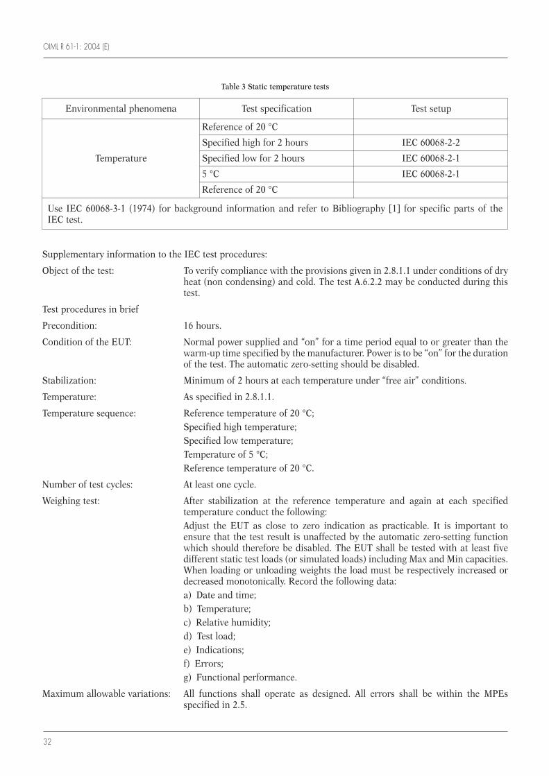
OIML R 61-1: 2004 (E)
32
Supplementary information to the IEC test procedures:
Object of the test: To verify compliance with the provisions given in 2.8.1.1 under conditions of dryheat (non condensing) and cold. The test A.6.2.2 may be conducted during thistest.
Test procedures in brief
Precondition: 16 hours.
Condition of the EUT: Normal power supplied and “on” for a time period equal to or greater than thewarm-up time specified by the manufacturer. Power is to be “on” for the durationof the test. The automatic zero-setting should be disabled.
Stabilization: Minimum of 2 hours at each temperature under “free air” conditions.
Temperature: As specified in 2.8.1.1.
Temperature sequence: Reference temperature of 20 °C;Specified high temperature;Specified low temperature;Temperature of 5 °C;Reference temperature of 20 °C.
Number of test cycles: At least one cycle.
Weighing test: After stabilization at the reference temperature and again at each specifiedtemperature conduct the following:Adjust the EUT as close to zero indication as practicable. It is important toensure that the test result is unaffected by the automatic zero-setting functionwhich should therefore be disabled. The EUT shall be tested with at least fivedifferent static test loads (or simulated loads) including Max and Min capacities.When loading or unloading weights the load must be respectively increased ordecreased monotonically. Record the following data:a) Date and time;b) Temperature;c) Relative humidity;d) Test load;e) Indications;f) Errors;g) Functional performance.
Maximum allowable variations: All functions shall operate as designed. All errors shall be within the MPEsspecified in 2.5.
Environmental phenomena Test specification Test setup
Reference of 20 °C
Specified high for 2 hours IEC 60068-2-2
Temperature Specified low for 2 hours IEC 60068-2-1
5 °C IEC 60068-2-1
Reference of 20 °C
Use IEC 60068-3-1 (1974) for background information and refer to Bibliography [1] for specific parts of theIEC test.
Table 3 Static temperature tests
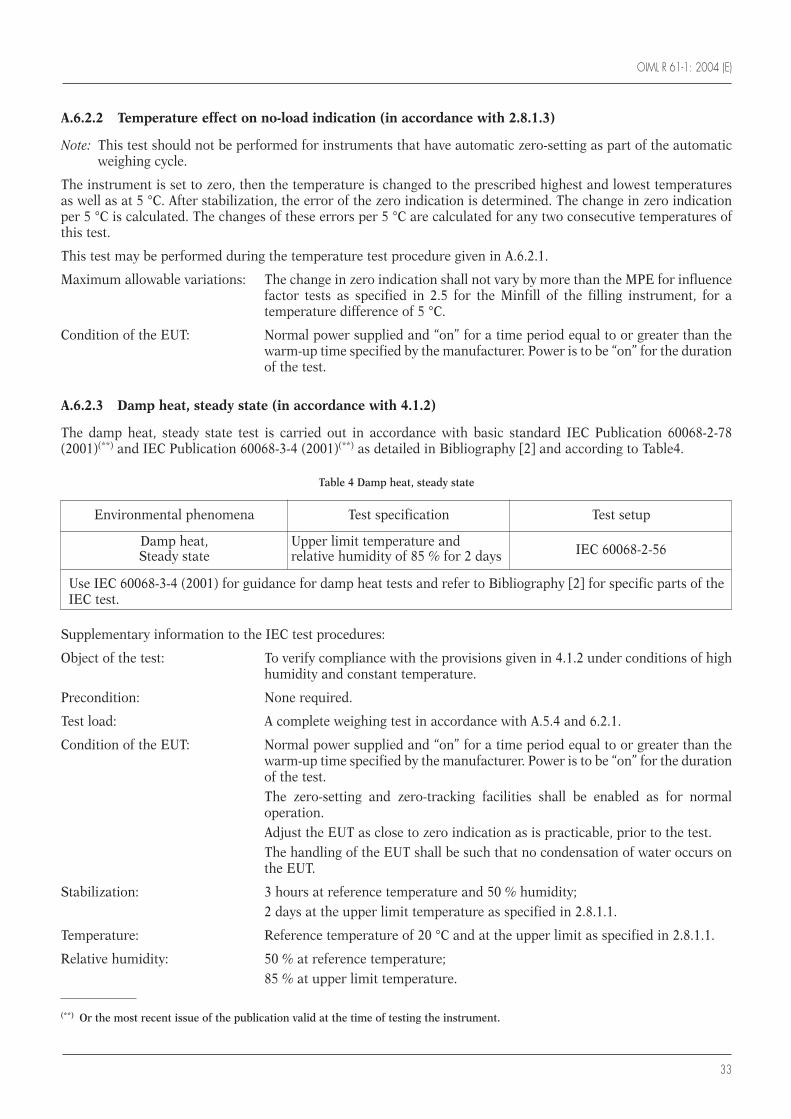
OIML R 61-1: 2004 (E)
33
A.6.2.2 Temperature effect on no-load indication (in accordance with 2.8.1.3)
Note: This test should not be performed for instruments that have automatic zero-setting as part of the automaticweighing cycle.
The instrument is set to zero, then the temperature is changed to the prescribed highest and lowest temperaturesas well as at 5 °C. After stabilization, the error of the zero indication is determined. The change in zero indicationper 5 °C is calculated. The changes of these errors per 5 °C are calculated for any two consecutive temperatures ofthis test.
This test may be performed during the temperature test procedure given in A.6.2.1.
Maximum allowable variations: The change in zero indication shall not vary by more than the MPE for influencefactor tests as specified in 2.5 for the Minfill of the filling instrument, for atemperature difference of 5 °C.
Condition of the EUT: Normal power supplied and “on” for a time period equal to or greater than thewarm-up time specified by the manufacturer. Power is to be “on” for the durationof the test.
A.6.2.3 Damp heat, steady state (in accordance with 4.1.2)
The damp heat, steady state test is carried out in accordance with basic standard IEC Publication 60068-2-78(2001)(**) and IEC Publication 60068-3-4 (2001)(**) as detailed in Bibliography [2] and according to Table4.
Environmental phenomena Test specification Test setup
Damp heat, Upper limit temperature andSteady state relative humidity of 85 % for 2 days IEC 60068-2-56
Use IEC 60068-3-4 (2001) for guidance for damp heat tests and refer to Bibliography [2] for specific parts of theIEC test.
Table 4 Damp heat, steady state
Supplementary information to the IEC test procedures:
Object of the test: To verify compliance with the provisions given in 4.1.2 under conditions of highhumidity and constant temperature.
Precondition: None required.
Test load: A complete weighing test in accordance with A.5.4 and 6.2.1.
Condition of the EUT: Normal power supplied and “on” for a time period equal to or greater than thewarm-up time specified by the manufacturer. Power is to be “on” for the durationof the test.The zero-setting and zero-tracking facilities shall be enabled as for normaloperation.Adjust the EUT as close to zero indication as is practicable, prior to the test.The handling of the EUT shall be such that no condensation of water occurs onthe EUT.
Stabilization: 3 hours at reference temperature and 50 % humidity;2 days at the upper limit temperature as specified in 2.8.1.1.
Temperature: Reference temperature of 20 °C and at the upper limit as specified in 2.8.1.1.
Relative humidity: 50 % at reference temperature;85 % at upper limit temperature.
(**) Or the most recent issue of the publication valid at the time of testing the instrument.
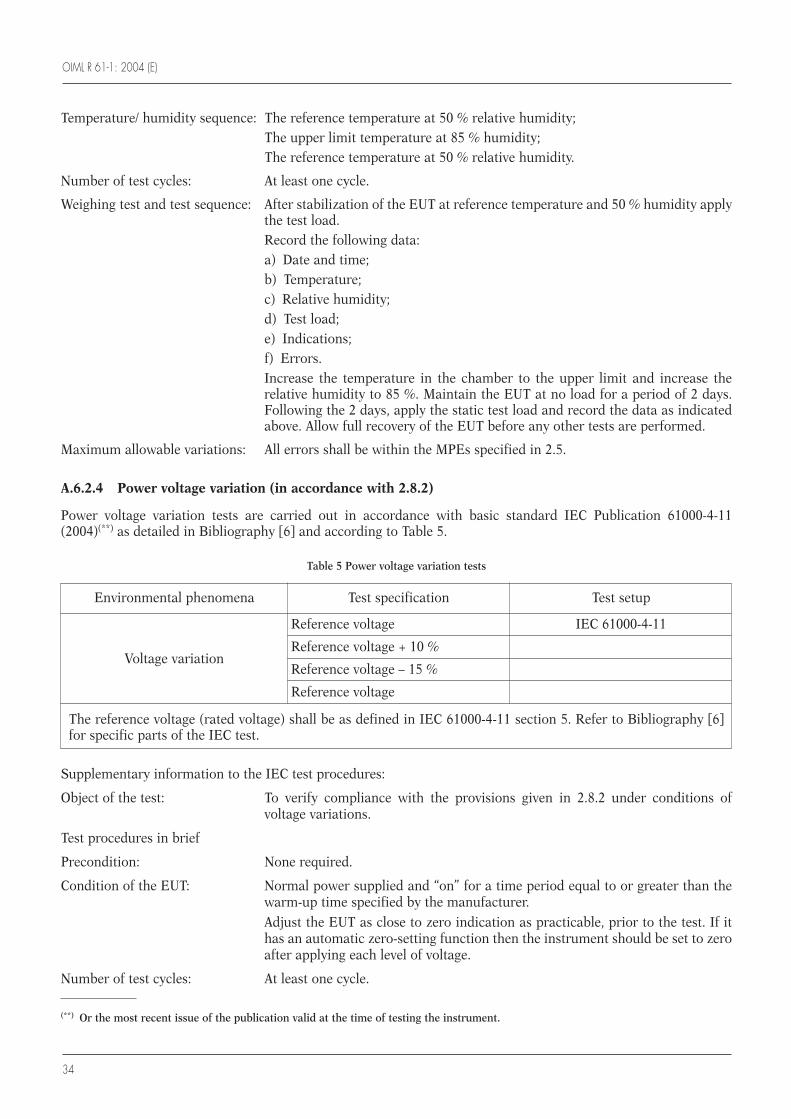
OIML R 61-1: 2004 (E)
34
Temperature/ humidity sequence: The reference temperature at 50 % relative humidity;The upper limit temperature at 85 % humidity;The reference temperature at 50 % relative humidity.
Number of test cycles: At least one cycle.
Weighing test and test sequence: After stabilization of the EUT at reference temperature and 50 % humidity applythe test load.Record the following data:a) Date and time;b) Temperature;c) Relative humidity;d) Test load;e) Indications;f) Errors.Increase the temperature in the chamber to the upper limit and increase therelative humidity to 85 %. Maintain the EUT at no load for a period of 2 days.Following the 2 days, apply the static test load and record the data as indicatedabove. Allow full recovery of the EUT before any other tests are performed.
Maximum allowable variations: All errors shall be within the MPEs specified in 2.5.
A.6.2.4 Power voltage variation (in accordance with 2.8.2)
Power voltage variation tests are carried out in accordance with basic standard IEC Publication 61000-4-11(2004)(**) as detailed in Bibliography [6] and according to Table 5.
(**) Or the most recent issue of the publication valid at the time of testing the instrument.
Environmental phenomena Test specification Test setup
Reference voltage IEC 61000-4-11
Reference voltage + 10 %Voltage variation
Reference voltage – 15 %
Reference voltage
The reference voltage (rated voltage) shall be as defined in IEC 61000-4-11 section 5. Refer to Bibliography [6]for specific parts of the IEC test.
Table 5 Power voltage variation tests
Supplementary information to the IEC test procedures:
Object of the test: To verify compliance with the provisions given in 2.8.2 under conditions ofvoltage variations.
Test procedures in brief
Precondition: None required.
Condition of the EUT: Normal power supplied and “on” for a time period equal to or greater than thewarm-up time specified by the manufacturer.
Adjust the EUT as close to zero indication as practicable, prior to the test. If ithas an automatic zero-setting function then the instrument should be set to zeroafter applying each level of voltage.
Number of test cycles: At least one cycle.
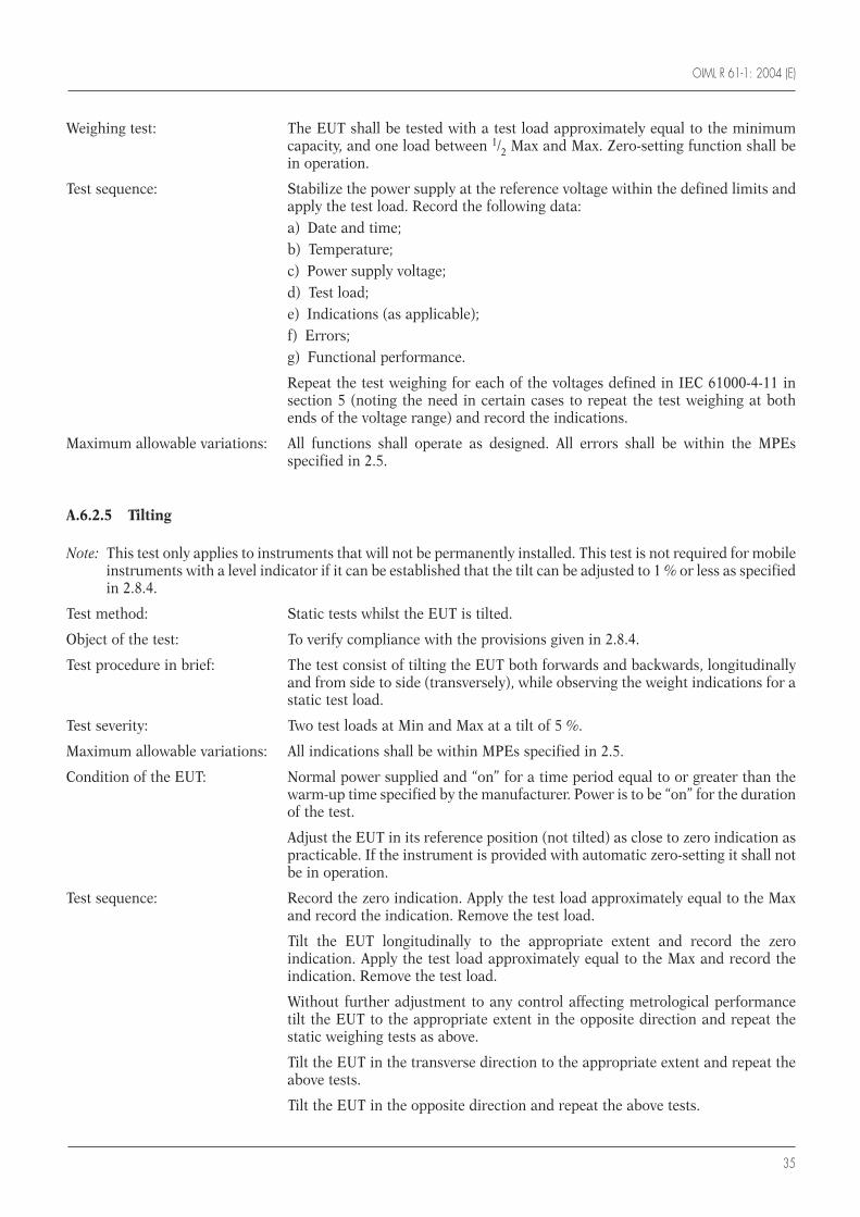
OIML R 61-1: 2004 (E)
35
Weighing test: The EUT shall be tested with a test load approximately equal to the minimumcapacity, and one load between 1/2 Max and Max. Zero-setting function shall bein operation.
Test sequence: Stabilize the power supply at the reference voltage within the defined limits andapply the test load. Record the following data:a) Date and time;b) Temperature;c) Power supply voltage;d) Test load;e) Indications (as applicable);f) Errors;g) Functional performance.
Repeat the test weighing for each of the voltages defined in IEC 61000-4-11 insection 5 (noting the need in certain cases to repeat the test weighing at bothends of the voltage range) and record the indications.
Maximum allowable variations: All functions shall operate as designed. All errors shall be within the MPEsspecified in 2.5.
A.6.2.5 Tilting
Note: This test only applies to instruments that will not be permanently installed. This test is not required for mobileinstruments with a level indicator if it can be established that the tilt can be adjusted to 1 % or less as specifiedin 2.8.4.
Test method: Static tests whilst the EUT is tilted.
Object of the test: To verify compliance with the provisions given in 2.8.4.
Test procedure in brief: The test consist of tilting the EUT both forwards and backwards, longitudinallyand from side to side (transversely), while observing the weight indications for astatic test load.
Test severity: Two test loads at Min and Max at a tilt of 5 %.
Maximum allowable variations: All indications shall be within MPEs specified in 2.5.
Condition of the EUT: Normal power supplied and “on” for a time period equal to or greater than thewarm-up time specified by the manufacturer. Power is to be “on” for the durationof the test.
Adjust the EUT in its reference position (not tilted) as close to zero indication aspracticable. If the instrument is provided with automatic zero-setting it shall notbe in operation.
Test sequence: Record the zero indication. Apply the test load approximately equal to the Maxand record the indication. Remove the test load.
Tilt the EUT longitudinally to the appropriate extent and record the zeroindication. Apply the test load approximately equal to the Max and record theindication. Remove the test load.
Without further adjustment to any control affecting metrological performancetilt the EUT to the appropriate extent in the opposite direction and repeat thestatic weighing tests as above.
Tilt the EUT in the transverse direction to the appropriate extent and repeat theabove tests.
Tilt the EUT in the opposite direction and repeat the above tests.
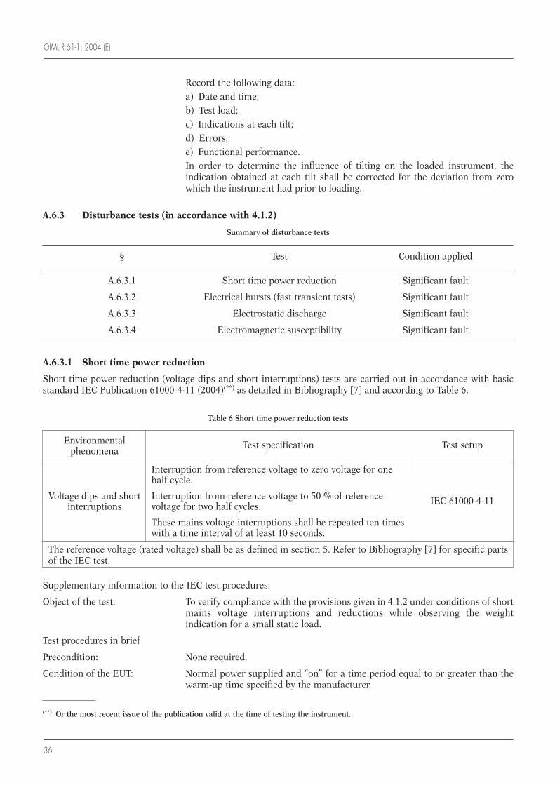
OIML R 61-1: 2004 (E)
36
Record the following data:a) Date and time;b) Test load;c) Indications at each tilt;d) Errors;e) Functional performance.In order to determine the influence of tilting on the loaded instrument, theindication obtained at each tilt shall be corrected for the deviation from zerowhich the instrument had prior to loading.
A.6.3 Disturbance tests (in accordance with 4.1.2)
Summary of disturbance tests
§ Test Condition applied
A.6.3.1 Short time power reduction Significant fault
A.6.3.2 Electrical bursts (fast transient tests) Significant fault
A.6.3.3 Electrostatic discharge Significant fault
A.6.3.4 Electromagnetic susceptibility Significant fault
A.6.3.1 Short time power reduction
Short time power reduction (voltage dips and short interruptions) tests are carried out in accordance with basicstandard IEC Publication 61000-4-11 (2004)(**) as detailed in Bibliography [7] and according to Table 6.
(**) Or the most recent issue of the publication valid at the time of testing the instrument.
Environmental Test specification Test setupphenomena
Interruption from reference voltage to zero voltage for onehalf cycle.
Voltage dips and short Interruption from reference voltage to 50 % of referenceinterruptions voltage for two half cycles. IEC 61000-4-11
These mains voltage interruptions shall be repeated ten timeswith a time interval of at least 10 seconds.
The reference voltage (rated voltage) shall be as defined in section 5. Refer to Bibliography [7] for specific partsof the IEC test.
Table 6 Short time power reduction tests
Supplementary information to the IEC test procedures:
Object of the test: To verify compliance with the provisions given in 4.1.2 under conditions of shortmains voltage interruptions and reductions while observing the weightindication for a small static load.
Test procedures in brief
Precondition: None required.
Condition of the EUT: Normal power supplied and “on” for a time period equal to or greater than thewarm-up time specified by the manufacturer.
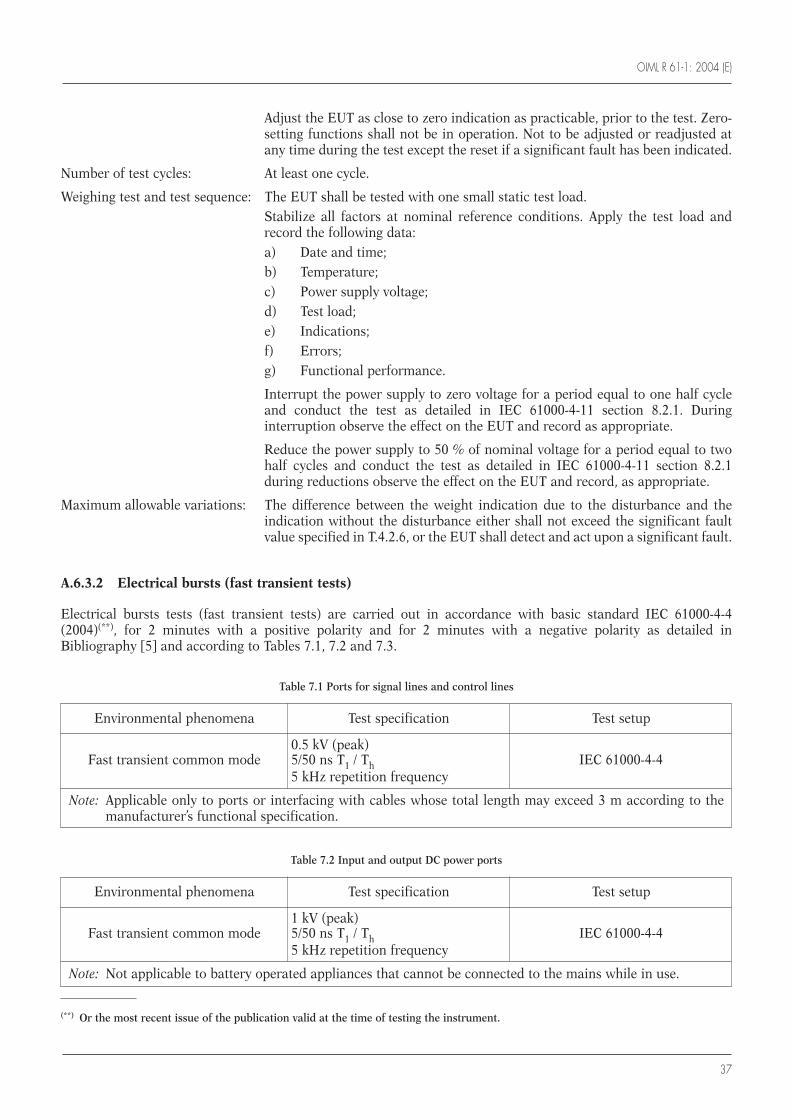
OIML R 61-1: 2004 (E)
37
Adjust the EUT as close to zero indication as practicable, prior to the test. Zero-setting functions shall not be in operation. Not to be adjusted or readjusted atany time during the test except the reset if a significant fault has been indicated.
Number of test cycles: At least one cycle.
Weighing test and test sequence: The EUT shall be tested with one small static test load.Stabilize all factors at nominal reference conditions. Apply the test load andrecord the following data:a) Date and time;b) Temperature;c) Power supply voltage;d) Test load;e) Indications;f) Errors;g) Functional performance.
Interrupt the power supply to zero voltage for a period equal to one half cycleand conduct the test as detailed in IEC 61000-4-11 section 8.2.1. Duringinterruption observe the effect on the EUT and record as appropriate.
Reduce the power supply to 50 % of nominal voltage for a period equal to twohalf cycles and conduct the test as detailed in IEC 61000-4-11 section 8.2.1during reductions observe the effect on the EUT and record, as appropriate.
Maximum allowable variations: The difference between the weight indication due to the disturbance and theindication without the disturbance either shall not exceed the significant faultvalue specified in T.4.2.6, or the EUT shall detect and act upon a significant fault.
A.6.3.2 Electrical bursts (fast transient tests)
Electrical bursts tests (fast transient tests) are carried out in accordance with basic standard IEC 61000-4-4(2004)(**), for 2 minutes with a positive polarity and for 2 minutes with a negative polarity as detailed inBibliography [5] and according to Tables 7.1, 7.2 and 7.3.
(**) Or the most recent issue of the publication valid at the time of testing the instrument.
Environmental phenomena Test specification Test setup
0.5 kV (peak)Fast transient common mode 5/50 ns T1 / Th IEC 61000-4-4
5 kHz repetition frequency
Note: Applicable only to ports or interfacing with cables whose total length may exceed 3 m according to themanufacturer’s functional specification.
Table 7.1 Ports for signal lines and control lines
Environmental phenomena Test specification Test setup
1 kV (peak)Fast transient common mode 5/50 ns T1 / Th IEC 61000-4-4
5 kHz repetition frequency
Note: Not applicable to battery operated appliances that cannot be connected to the mains while in use.
Table 7.2 Input and output DC power ports
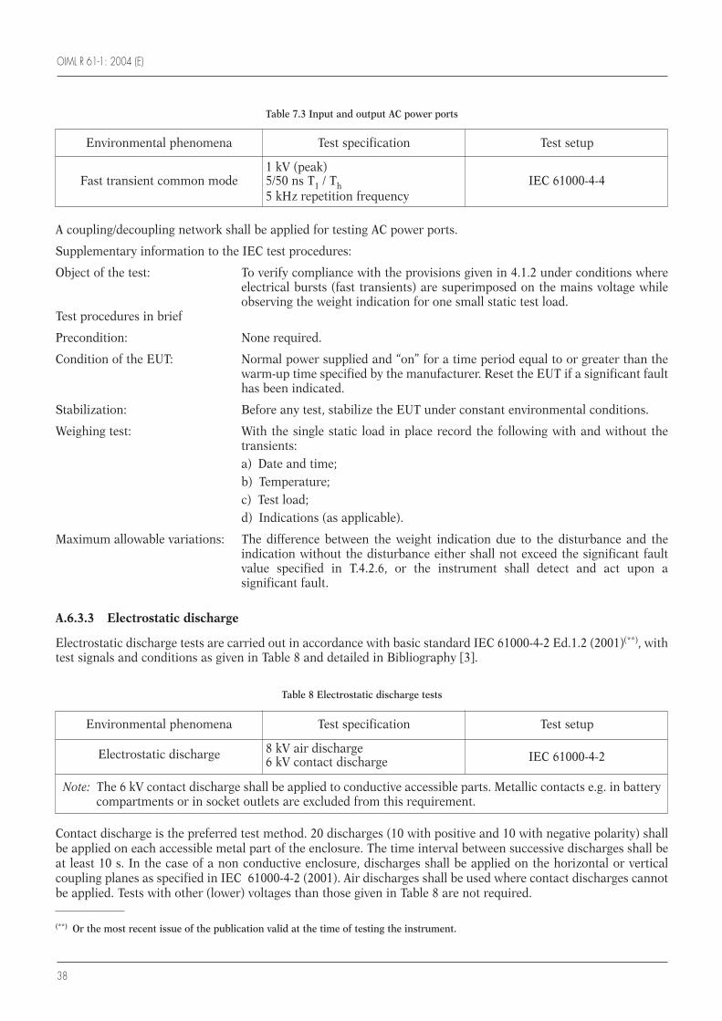
OIML R 61-1: 2004 (E)
38
A coupling/decoupling network shall be applied for testing AC power ports.
Supplementary information to the IEC test procedures:
Object of the test: To verify compliance with the provisions given in 4.1.2 under conditions whereelectrical bursts (fast transients) are superimposed on the mains voltage whileobserving the weight indication for one small static test load.
Test procedures in brief
Precondition: None required.
Condition of the EUT: Normal power supplied and “on” for a time period equal to or greater than thewarm-up time specified by the manufacturer. Reset the EUT if a significant faulthas been indicated.
Stabilization: Before any test, stabilize the EUT under constant environmental conditions.
Weighing test: With the single static load in place record the following with and without thetransients:a) Date and time;b) Temperature;c) Test load;d) Indications (as applicable).
Maximum allowable variations: The difference between the weight indication due to the disturbance and theindication without the disturbance either shall not exceed the significant faultvalue specified in T.4.2.6, or the instrument shall detect and act upon asignificant fault.
A.6.3.3 Electrostatic discharge
Electrostatic discharge tests are carried out in accordance with basic standard IEC 61000-4-2 Ed.1.2 (2001)(**), withtest signals and conditions as given in Table 8 and detailed in Bibliography [3].
Environmental phenomena Test specification Test setup
1 kV (peak)Fast transient common mode 5/50 ns T1 / Th IEC 61000-4-4
5 kHz repetition frequency
Table 7.3 Input and output AC power ports
(**) Or the most recent issue of the publication valid at the time of testing the instrument.
Environmental phenomena Test specification Test setup
Electrostatic discharge 8 kV air dischargeIEC 61000-4-26 kV contact discharge
Note: The 6 kV contact discharge shall be applied to conductive accessible parts. Metallic contacts e.g. in batterycompartments or in socket outlets are excluded from this requirement.
Table 8 Electrostatic discharge tests
Contact discharge is the preferred test method. 20 discharges (10 with positive and 10 with negative polarity) shallbe applied on each accessible metal part of the enclosure. The time interval between successive discharges shall beat least 10 s. In the case of a non conductive enclosure, discharges shall be applied on the horizontal or verticalcoupling planes as specified in IEC 61000-4-2 (2001). Air discharges shall be used where contact discharges cannotbe applied. Tests with other (lower) voltages than those given in Table 8 are not required.
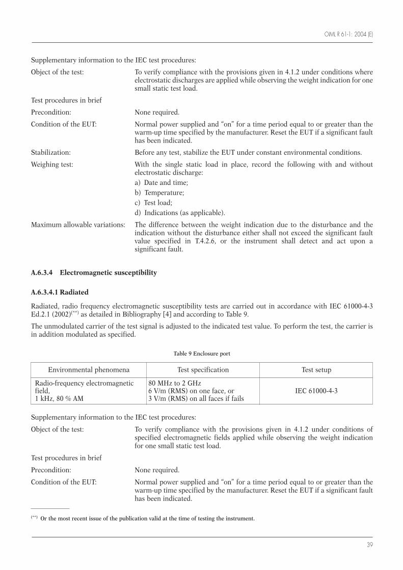
OIML R 61-1: 2004 (E)
39
Supplementary information to the IEC test procedures:
Object of the test: To verify compliance with the provisions given in 4.1.2 under conditions whereelectrostatic discharges are applied while observing the weight indication for onesmall static test load.
Test procedures in brief
Precondition: None required.
Condition of the EUT: Normal power supplied and “on” for a time period equal to or greater than thewarm-up time specified by the manufacturer. Reset the EUT if a significant faulthas been indicated.
Stabilization: Before any test, stabilize the EUT under constant environmental conditions.
Weighing test: With the single static load in place, record the following with and withoutelectrostatic discharge:a) Date and time;b) Temperature;c) Test load;d) Indications (as applicable).
Maximum allowable variations: The difference between the weight indication due to the disturbance and theindication without the disturbance either shall not exceed the significant faultvalue specified in T.4.2.6, or the instrument shall detect and act upon asignificant fault.
A.6.3.4 Electromagnetic susceptibility
A.6.3.4.1 Radiated
Radiated, radio frequency electromagnetic susceptibility tests are carried out in accordance with IEC 61000-4-3Ed.2.1 (2002)(**) as detailed in Bibliography [4] and according to Table 9.
The unmodulated carrier of the test signal is adjusted to the indicated test value. To perform the test, the carrier isin addition modulated as specified.
(**) Or the most recent issue of the publication valid at the time of testing the instrument.
Environmental phenomena Test specification Test setup
Radio-frequency electromagnetic 80 MHz to 2 GHzfield, 6 V/m (RMS) on one face, or IEC 61000-4-31 kHz, 80 % AM 3 V/m (RMS) on all faces if fails
Table 9 Enclosure port
Supplementary information to the IEC test procedures:
Object of the test: To verify compliance with the provisions given in 4.1.2 under conditions ofspecified electromagnetic fields applied while observing the weight indicationfor one small static test load.
Test procedures in brief
Precondition: None required.
Condition of the EUT: Normal power supplied and “on” for a time period equal to or greater than thewarm-up time specified by the manufacturer. Reset the EUT if a significant faulthas been indicated.
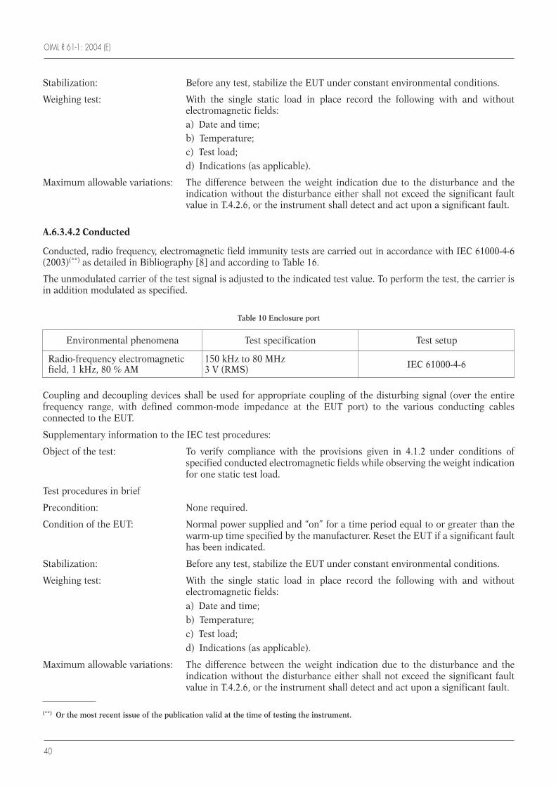
OIML R 61-1: 2004 (E)
40
Stabilization: Before any test, stabilize the EUT under constant environmental conditions.
Weighing test: With the single static load in place record the following with and withoutelectromagnetic fields:a) Date and time;b) Temperature;c) Test load;d) Indications (as applicable).
Maximum allowable variations: The difference between the weight indication due to the disturbance and theindication without the disturbance either shall not exceed the significant faultvalue in T.4.2.6, or the instrument shall detect and act upon a significant fault.
A.6.3.4.2 Conducted
Conducted, radio frequency, electromagnetic field immunity tests are carried out in accordance with IEC 61000-4-6(2003)(**) as detailed in Bibliography [8] and according to Table 16.
The unmodulated carrier of the test signal is adjusted to the indicated test value. To perform the test, the carrier isin addition modulated as specified.
(**) Or the most recent issue of the publication valid at the time of testing the instrument.
Environmental phenomena Test specification Test setup
Radio-frequency electromagnetic 150 kHz to 80 MHz IEC 61000-4-6field, 1 kHz, 80 % AM 3 V (RMS)
Table 10 Enclosure port
Coupling and decoupling devices shall be used for appropriate coupling of the disturbing signal (over the entirefrequency range, with defined common-mode impedance at the EUT port) to the various conducting cablesconnected to the EUT.
Supplementary information to the IEC test procedures:
Object of the test: To verify compliance with the provisions given in 4.1.2 under conditions ofspecified conducted electromagnetic fields while observing the weight indicationfor one static test load.
Test procedures in brief
Precondition: None required.
Condition of the EUT: Normal power supplied and “on” for a time period equal to or greater than thewarm-up time specified by the manufacturer. Reset the EUT if a significant faulthas been indicated.
Stabilization: Before any test, stabilize the EUT under constant environmental conditions.
Weighing test: With the single static load in place record the following with and withoutelectromagnetic fields:a) Date and time;b) Temperature;c) Test load;d) Indications (as applicable).
Maximum allowable variations: The difference between the weight indication due to the disturbance and theindication without the disturbance either shall not exceed the significant faultvalue in T.4.2.6, or the instrument shall detect and act upon a significant fault.
OIML R 61-1: 2004 (E)
41
A.6.4 Disturbances on DC voltage powered instruments (2.8.3)
Electronic measuring systems supplied with DC voltage shall fulfill the:a) Influence factor tests in A.6.2; andb) Disturbance tests in A.6.3,
with the exception of:a) Power voltage variation tests in A.6.2.4; b) Short time power reduction in A.6.3.1; andc) Electrical bursts in A.6.3.2,
which are to be replaced by the following provisions.
A.6.4.1 General provision
For under-voltages and over-voltages all errors shall be within the MPEs specified in 2.5 when the instrument is stilloperating.
The under-voltage or over-voltage is applied for a complete measurement or part of a measurement.
A.7 Span stability test (in accordance with 4.3.3)
Test method: Span stability.
Object of the test: To verify compliance with the provisions given in 4.3.3 after the EUT has beensubjected to the performance tests.
References to standards: No references to international standards are given.
Test procedure in brief: The test consists of observing the variations of error of the EUT undersufficiently constant ambient conditions (reasonably constant conditions in anormal laboratory environment) at various intervals, before, during and after theEUT has been subjected to performance tests.
The performance tests shall include the temperature test and, if applicable, thedamp heat test. Other performance tests listed in this Annex may be performed.
The EUT shall be disconnected from the mains power supply, or battery supplywhere fitted, two times for at least 8 hours during the period of the test. Thenumber of disconnections may be increased if the manufacturer of theinstrument specifies so or at the discretion of the approved authority in theabsence of any such specification.
In the conduct of this test, the operating instructions for the instrument assupplied by the manufacturer shall be considered.
The EUT shall be stabilized at sufficiently constant ambient conditions afterswitch-on for at least 5 hours, and at least 16 hours after the temperature anddamp heat tests have been performed.
Test severities: Test duration: 28 days or over the period necessary for the conduct of theperformance tests, whichever is less.
Time t (days) between tests: 0.5 ≤ t ≤ 10
Test load: A static test load near Max; the same test weights shall be used throughout thetest.
Maximum allowable variations: The variation in the indication of the test load shall not exceed half of theabsolute value of the MPE for influence factor tests (2.5) for the test load appliedon any of the (n) tests conducted.
OIML R 61-1: 2004 (E)
42
Number of tests (n): n ≥ 8. If the test results indicate a trend more than half the permissible variationspecified above, conduct additional tests until the trend comes to rest or reversesitself, or until the error exceeds the maximum permissible variation.
Precondition: None required.
Test equipment: Verified mass standards.
Condition of the EUT: Adjust the EUT as close to zero indication as practicable before each test.
Test sequence: Stabilize all factors at nominal reference conditions. If the instrument isprovided with automatic zero-setting it shall not be in operation.Apply the test load (or simulated load) and record the following data:a) Date and time;b) Temperature;c) Barometric pressure;d) Relative humidity;e) Test load;f) Indication;g) Errors;h) Changes in test location.Apply all necessary corrections resulting from variations of temperature,pressure, etc. between the various measurements.At the first measurement immediately repeat zeroing and loading four times todetermine the average value of error. For the next measurements perform onlyone, unless either the result is outside the specified tolerance or the range of thefive readings of the initial measurement was more than 1/10 of the maximumpermissible variation.Repeat this test at periodic intervals during and after the conduct of the variousperformance tests.Allow full recovery of the EUT before any other tests are performed.
A.8 Procedure for material tests
A.8.1 Material tests at type evaluation (in accordance with 5.2.3.1)
Operational tests with material shall be done on a complete instrument to assess compliance with the requirementsof clause 3 with material for the test load as specified in 5.2.3.1.
A.8.1.1 Feeding device (details as given in 3.6)
Check that the feeding device provides a sufficient and regular flow rate.
Check that any adjustable feed device has an indication of the direction of movement corresponding to the sense ofthe adjustment of the feed (where applicable).
For instruments using the subtractive weighing principle check that residual material retained at the feeding deviceafter each load is delivered, is negligible relative to limits of error.
A.8.1.2 Load receptor (details as given in 3.7)
For instruments that weigh material in a separate load receptor prior to discharge to a container:• Check that the residual material retained at the load receptor after each discharge is negligible relative to limits
of error;
• Check that manual discharge of the load receptor is not possible during automatic operation.
OIML R 61-1: 2004 (E)
43
A.8.2 Material tests at initial verification (in accordance with 5.3.2)
Metrological tests with material shall be done on a complete filling instrument, fully assembled and fixed in theposition in which it is intended to be used and as specified in 5.3.2.
The accuracy class X(x) (or classes) shall be determined from the results.
A.8.2.1 Requirements for metrological material tests
• Types of loads shall be as specified in 6.2.2;• Mass of test loads and fills shall be as specified in 6.2.1 a, b and c;• Condition of material tests shall be as specified in 6.2.3;• Number of fills shall be as specified in 6.3.
A.8.2.2 Methods for metrological material tests (as given in 6.5)
One of the following verifications methods shall be used:• Separate verification method: the separate verification method is as defined in 6.5.1;• Integral verification method: the integral verification method is as defined in 6.5.2.
A.8.2.3 Procedure for metrological material tests
1) Set up the instrument in accordance with the conditions of test given in 6.2.3.
2) Select a preset value for the fill and set the load value if different from the fill, in accordance with values of themass of the fills as specified in 6.2.1. Record the indicated preset value.
3) Run the instrument to produce a number of fills as specified in 6.3 using types of test loads specified in 6.2.2.
4) Weigh all the fills by either:• Separate verification method specified in 6.5.1; or• The integral verification method specified in 6.5.2
to determine the mass of fill in accordance with 6.7 so that the result of weighing the test fill on the controlinstrument shall be considered as the conventional true value of the test fill.
5) In accordance with 6.7 calculate the average value of all the fills in the test as follows:∑ F / n
where: F is the mass of the fill (conventional true value), in units of mass; andn is the number of fills in the test.
6) In accordance with 6.8 calculate the deviation of each fill from the average of all the fills in the test as follows:|md| = F – (∑ F / n)
where: md is the deviation from average, in units of mass.
7) Repeat steps 2) to 6) for other loads as specified for values of the mass of the fills in 6.2.1.
A.8.2.4 Determination of accuracy class, X(x) (in accordance with 5.2.5)
1) For each preset value of the test fill, FP:
• Calculate the preset value error specified in 2.4 in accordance with 6.9 as follows:|se| = (∑ F / n) – FP
where: se is the preset value error.
• Determine the maximum permissible preset value error for class X(1), MPSE(1) as follows:
MPSE(1) = 0.25 MPD(1) for in-service inspection, corresponding to the value of a fill equal to FP
• Then calculate: |se| / MPSE(1).
OIML R 61-1: 2004 (E)
44
2) For each preset value of the test fill, FP:
• Determine the maximum (largest) of the absolute values of the actual deviation from the average i.e. mdmax.
• Determine the maximum permissible deviation from the average for class X(1), MPD(1).
• Then calculate: mdmax / MPD(1).
3) From 1) determine the maximum (largest) value of |se|/ MPSE(1),
i.e. [|se| / MPSE(1)]max from all the preset test fills.
4) From 2) determine the maximum (largest) value of mdmax / MPD(1),
i.e. [mdmax / MPD(1)]max from all the preset test fills.
5) Determine the accuracy class (x) such that
(x) ≥ [|se| / MPSE(1)]max
and (x) ≥ [mdmax/ MPD(1)]max
and (x) = 1 × 10k, 2 × 10k, or 5 × 10k,
the index k being a positive or negative whole number or zero.
OIML R 61-1: 2004 (E)
45
Below are references to Publications of the International Electrotechnical Commission (IEC), where mention is made in some of thetests in Annex A. Use these or the most recent issue of the publication valid at the time of testing the instrument.
[1] IEC Publication 60068-2-1 (1994) Basic environmental testing procedures. Part 2: Tests, Test Ad: Cold, for heatdissipating equipment under test (EUT), with gradual change of temperature.
IEC Publication 60068-2-2 (1994) Basic environmental testing procedures, Part 2: Tests, Test Bd: Dry heat, for heatdissipating equipment under test (EUT) with gradual change of temperature.
IEC Publication 60068-3-1 (1974): Background information, Section 1: Cold and dry heat tests.
[2] IEC Publication 60068-2-78 (2001): Environmental testing, Part 2: Tests, Test Cb: Damp heat, steady state. Primarily forequipment.
IEC Publication 60068-3-4 (2001): Environmental testing, Part 3-4: Supporting documentation and guidance for dampheat tests.
[3] IEC Publication 61000-4-2 Ed.1.2 (2001) Electromagnetic Compatibility (EMC), Part 4: Testing and measurement techniquesConsolidated Edition: - Section 2: Electrostatic discharge immunity test.
[4] IEC Publication 61000-4-3 (2002): Electromagnetic Compatibility (EMC), Part 4: Testing and measurement techniques- Section 3: Radiated, radio-frequency, electromagnetic field immunity test.
[5] IEC Publication 61000-4-4 (2004): Electromagnetic Compatibility (EMC), Part 4: Testing and measurement techniques- Section 4: Electrical fast transient/burst immunity test.
[6] IEC Publication 61000-4-11 (2004): Electromagnetic compatibility (EMC), Part 4: Testing and measurement techniques- Section 11: Voltage dips, short interruptions and voltage variations immunitytests. Section 5.2 (Test levels - Voltage variation). Section 8.2.2 (Execution of thetest-voltage variation).
[7] IEC Publication 61000-4-11 (2004): Electromagnetic compatibility (EMC), Part 4: Testing and measurement techniques- Section 11: Voltage dips, short interruptions and voltage variations immunitytests. Section 5.1 (Test levels - Voltage dips and short interruptions). Section 8.2.1(Execution of the test-voltage dips and short interruptions).
[8] IEC Publication 61000-4-6 (2003): Electromagnetic Compatibility (EMC) Part 4: Testing and measurement techniques- Section 6: Immunity to conducted disturbances, induced by radio-frequency field.
Bibliography
with amendment 2:
with amendment 2:
with amendment 1:


OIML R 61-1: 2004 (E)
Printed in France GRANDE IMPRIMERIE DE TROYES