MultiRAE Plus - raesystems.com · Danger Risque D’origine Electrostatique Nettoyer uniquement...
52
MultiRAE Plus USER MANUAL PGM-50/4, PGM-50/4P, PGM-50/5P Multiple-Gas Monitor
Transcript of MultiRAE Plus - raesystems.com · Danger Risque D’origine Electrostatique Nettoyer uniquement...
MultiRAE Plus
User ManUal
PGM-50/4, PGM-50/4P, PGM-50/5PMultiple-Gas Monitor
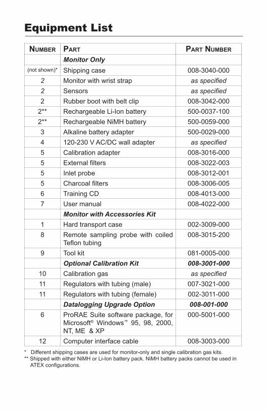
Equipment List
nUMber Part Part nUMber
Monitor Only(not shown)* Shipping case 008-3040-000
2 Monitor with wrist strap as specified2 Sensors as specified2 Rubber boot with belt clip 008-3042-000
2** Rechargeable Li-Ion battery 500-0037-1002** Rechargeable NiMH battery 500-0059-0003 Alkaline battery adapter 500-0029-0004 120-230 V AC/DC wall adapter as specified5 Calibration adapter 008-3016-0005 External filters 008-3022-0035 Inlet probe 008-3012-0015 Charcoal filters 008-3006-0056 Training CD 008-4013-0007 User manual 008-4022-000
Monitor with Accessories Kit1 Hard transport case 002-3009-0008 Remote sampling probe with coiled
Teflon tubing008-3015-200
9 Tool kit 081-0005-000Optional Calibration Kit 008-3001-000
10 Calibration gas as specified11 Regulators with tubing (male) 007-3021-00011 Regulators with tubing (female) 002-3011-000
Datalogging Upgrade Option 008-001-0006 ProRAE Suite software package, for
Microsoft® Windows™ 95, 98, 2000, NT, ME & XP
000-5001-000
12 Computer interface cable 008-3003-000* Different shipping cases are used for monitor-only and single calibration gas kits.** Shipped with either NiMH or Li-Ion battery pack. NiMH battery packs cannot be used in
ATEX configurations.
i
6 78
11 9 10 10235 11 12 4
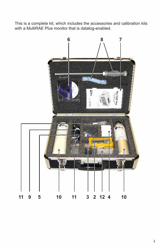
This is a complete kit, which includes the accessories and calibration kits with a MultiRAE Plus monitor that is datalog-enabled.
ii
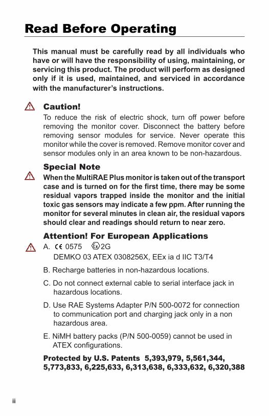
Caution!To reduce the risk of electric shock, turn off power before removing the monitor cover. Disconnect the battery before removing sensor modules for service. Never operate this monitor while the cover is removed. Remove monitor cover and sensor modules only in an area known to be non-hazardous.
Special NoteWhen the MultiRAE Plus monitor is taken out of the transport case and is turned on for the first time, there may be some residual vapors trapped inside the monitor and the initial toxic gas sensors may indicate a few ppm. After running the monitor for several minutes in clean air, the residual vapors should clear and readings should return to near zero.
Attention! For European ApplicationsA. 0575 II 2G
DEMKO 03 ATEX 0308256X, EEx ia d IIC T3/T4
B. Recharge batteries in non-hazardous locations.
C. Do not connect external cable to serial interface jack inhazardous locations.
D. Use RAE Systems Adapter P/N 500-0072 for connectionto communication port and charging jack only in a nonhazardous area.
E. NiMH battery packs (P/N 500-0059) cannot be used in ATEX configurations.
Protected by U.S. Patents 5,393,979, 5,561,344, 5,773,833, 6,225,633, 6,313,638, 6,333,632, 6,320,388
Read Before OperatingThis manual must be carefully read by all individuals who have or will have the responsibility of using, maintaining, or servicing this product. The product will perform as designed only if it is used, maintained, and serviced in accordance with the manufacturer’s instructions.
iii
Warnings
Battery PackUse only RAE Systems battery packs, part number 500-0029, 500-0037, or 500-0059. This instrument has not been tested in an explosive gas/air atmosphere having an oxygen concentration greater than 21%. Substitution of components may impair intrinsic safety. Recharge batteries only in non-hazardous atmospheres.
Computer InterfaceDo not transfer data by means of the computer interface cable in hazardous atmospheres.
Static HazardClean only with a damp cloth.
CalibrationThe calibration of any newly purchased RAE Systems Instrument should be tested by exposing it to known concentration calibration gases before the instrument is put into service for the first time. For safety, check the accuracy of the monitor by exposing the sensors to known concentration calibration gas(es) before each day’s use.
ReadingsAny rapid up-scale reading followed by a declining or erratic reading may indicate a gas concentration beyond upper scale limit, which may be hazardous.
For safety reasons this equipment must be operated and serviced by qualified personnel only. Read and understand the instruction manual completely before operating or servicing.
iv
Avertissements
Ensemble de BatterieUtiliser seulement l’ensemble de batterie RAE Systems avec numéro de série 500-0029, 500-0037, ou 500-0059. Cet instrument n’a pas été essayé dans une atmosphère de gaz/air explosive ayant une concentration d’oxygène plus élevée que 21%. La substitution de composants peut compromettre la sécurité intrinsèque. Ne charger les batteries que dans l’emplacement désigné non dangereux.
Câble de ComputerConnecter pas le câble externe que dans environnements non dangereux.
Danger Risque D’origine ElectrostatiqueNettoyer uniquement avec un chiffon humide.
La CalibrationLa calibration de toute instruments de RAE Systems doit être testé en exposant l’instrument à une concentration de gaz connue par une procédure die talonnage avant de mettre en service l’instrument pour la première fois. Pour une sécurité maximale, la sensibilité du MultiRAE Plus doit être vérifié en exposant l’instrument à une concentration de gaz connue par une procédure die talonnage avant chaque utilisation journalière.
Les LecturesToute lecture rapide et positive, suivie d’une baisse subite au erratique de la valeur, peut indiquer une concentration de gaz hors gamme de détection qui peut être dangereuse.
Pour des raisons de sécurité, cet équipement doit être utilisé, entretenu et réparé uniquement par un personnel qualifié. Étudier le manuel d’instructions en entier avant d’utiliser, d’entretenir ou de réparer l’équipement.
v
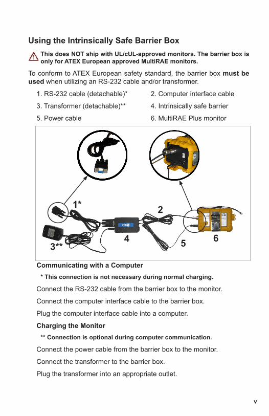
Using the Intrinsically Safe Barrier BoxThis does NOT ship with UL/cUL-approved monitors. The barrier box is only for ATEX European approved MultiRAE monitors.
To conform to ATEX European safety standard, the barrier box must be used when utilizing an RS-232 cable and/or transformer.
1. RS-232 cable (detachable)* 2. Computer interface cable
3. Transformer (detachable)** 4. Intrinsically safe barrier
5. Power cable 6. MultiRAE Plus monitor
Communicating with a Computer* This connection is not necessary during normal charging.
Connect the RS-232 cable from the barrier box to the monitor.
Connect the computer interface cable to the barrier box.
Plug the computer interface cable into a computer.
Charging the Monitor** Connection is optional during computer communication.
Connect the power cable from the barrier box to the monitor.
Connect the transformer to the barrier box.
Plug the transformer into an appropriate outlet.
4 53**
1*
6
2
vi
© 2003 RAE Systems, Inc.
SPECIAL NOTE: If the monitor needs to be serviced, contact either:
the RAE Systems distributor where the unit was purchased; they will return the monitor on the user’s behalf,
or the RAE Systems Technical Service department. Before returning the unit for service or repair, obtain a Returned Material Authorization (RMA) number for proper tracking of your equipment. This number needs to be on all documentation and posted on the outside of the box in which the monitor is returned for service or upgrade. Packages without RMA Numbers will be refused at the factory.
vii
Table of Contents
General Information • 1Dataloging-Enabled Monitors • 1Physical Description • 1Display • 1
Operating the MultiRAE Plus • 2Turning the Monitor On and Off • 2User Modes • 2Calibrating the Monitor • 5Getting Started • 5Span Gas Calibration • 6Fresh Air Calibration • 6Zero Organic Filters for Zeroing PID • 6Multiple Sensor Calibration • 7Calibrating the PID Sensor • 7Single Sensor Calibration • 8MultiRAE Plus Usage Overview • 9Alarm Signals • 10Preset Alarm Limits and Calibration • 12Back Light • 12Sampling Pump • 12Datalogging • 13Datalog Options • 13Charging the Battery Pack • 14
Accessories • 15External Filters • 15Remote Sampling Probe • 15Optional Dilution Fitting • 15Calibration Adapter • 16
viii
Programming Mode • 18Programming Menus • 19Security Levels • 20Calibrate Monitor • 21Change Alarm Limits • 21Change Datalog Setting • 22Change Monitor Setup • 23Change Sensor Configuration • 24Correction Factors • 25
Diagnostic Mode • 26Sensor Name and Raw Sensor Readings • 26RF Test (Radio Frequency) • 26Adjust Lamp Failure Threshold • 26Battery Type and Bias • 27Show x1 and x10 Range of PID Sensor • 27Display Contrast • 27LEL Power • 27Clock, Time, Battery, and Temperature • 28Sensor Expiration Date • 28Pump Stall • 28Back Light Threshold • 28Serial Number and Pump • 28Battery Duration Time • 28Communicate with PC • 28
Maintenance • 29Li-Ion Battery Pack • 30Replacing the Battery Pack • 30Emergency Alkaline Battery Adapter • 31Sensor Replacement • 32CO Sensor Charcoal Filters • 33Special Bias Voltage for Toxic Gas Sensors • 34PID Sensor Cleaning/Replacement • 35Taking Care of the Lamp • 35Sampling Pump Replacement • 36
Troubleshooting • 37Specifications • 39
Range, Resolution & Response Time • 40
Service and Repair Record • 41
General Information 1
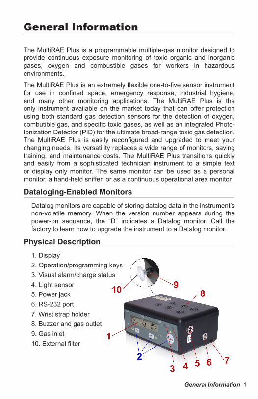
The MultiRAE Plus is a programmable multiple-gas monitor designed to provide continuous exposure monitoring of toxic organic and inorganic gases, oxygen and combustible gases for workers in hazardous environments.
The MultiRAE Plus is an extremely flexible one-to-five sensor instrument for use in confined space, emergency response, industrial hygiene, and many other monitoring applications. The MultiRAE Plus is the only instrument available on the market today that can offer protection using both standard gas detection sensors for the detection of oxygen, combutible gas, and specific toxic gases, as well as an integrated Photo-Ionization Detector (PID) for the ultimate broad-range toxic gas detection. The MultiRAE Plus is easily reconfigured and upgraded to meet your changing needs. Its versatility replaces a wide range of monitors, saving training, and maintenance costs. The MultiRAE Plus transitions quickly and easily from a sophisticated technician instrument to a simple text or display only monitor. The same monitor can be used as a personal monitor, a hand-held sniffer, or as a continuous operational area monitor.
Dataloging-Enabled MonitorsDatalog monitors are capable of storing datalog data in the instrument’s non-volatile memory. When the version number appears during the power-on sequence, the “D” indicates a Datalog monitor. Call the factory to learn how to upgrade the instrument to a Datalog monitor.
Physical Description1. Display2. Operation/programming keys3. Visual alarm/charge status4. Light sensor5. Power jack6. RS-232 port7. Wrist strap holder8. Buzzer and gas outlet9. Gas inlet10. External filter
General Information
2 Operating the MultiRAE Plus
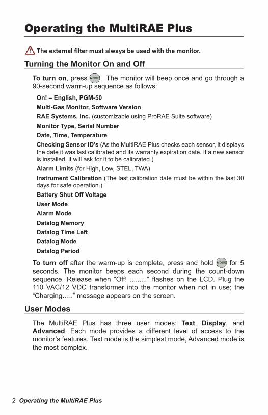
The external filter must always be used with the monitor.
Turning the Monitor On and OffTo turn on, press M . The monitor will beep once and go through a 90-second warm-up sequence as follows:
On! – English, PGM-50Multi-Gas Monitor, Software VersionRAE Systems, Inc. (customizable using ProRAE Suite software)Monitor Type, Serial NumberDate, Time, TemperatureChecking Sensor ID’s (As the MultiRAE Plus checks each sensor, it displays the date it was last calibrated and its warranty expiration date. If a new sensor is installed, it will ask for it to be calibrated.)Alarm Limits (for High, Low, STEL, TWA)Instrument Calibration (The last calibration date must be within the last 30 days for safe operation.)Battery Shut Off VoltageUser ModeAlarm ModeDatalog MemoryDatalog Time LeftDatalog ModeDatalog Period
To turn off after the warm-up is complete, press and hold M for 5 seconds. The monitor beeps each second during the count-down sequence. Release when “Off! .........” flashes on the LCD. Plug the 110 VAC/12 VDC transformer into the monitor when not in use; the “Charging…..” message appears on the screen.
User ModesThe MultiRAE Plus has three user modes: Text, Display, and Advanced. Each mode provides a different level of access to the monitor’s features. Text mode is the simplest mode, Advanced mode is the most complex.
Operating the MultiRAE Plus
Operating the MultiRAE Plus 3
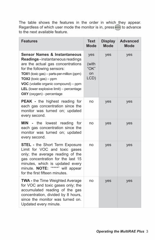
The table shows the features in the order in which they appear. Regardless of which user mode the monitor is in, press M to advance to the next available feature.
Features TextMode
DisplayMode
AdvancedMode
Sensor Names & Instantaneous Readings - instantaneous readings are the actual gas concentrations for the following sensors:TOX1 (toxic gas) – parts-per-million (ppm)TOX2 (toxic gas) – ppmVOC (volatile organic compound) – ppmLEL (lower explosive limit) – percentageOXY (oxygen) - percentage
yes
(with “OK” on
LCD)
yes yes
PEAK - the highest reading for each gas concentration since the monitor was turned on; updated every second.
no yes yes
MIN - the lowest reading for each gas concentration since the monitor was turned on; updated every second.
no yes yes
STEL - the Short Term Exposure Limit for VOC and toxic gases only; the average reading of the gas concentration for the last 15 minutes, which is updated every minute. NOTE: “****” will appear for the first fifteen minutes.
no yes yes
TWA - the Time Weighted Average for VOC and toxic gases only; the accumulated reading of the gas concentration, divided by 8 hours, since the monitor was turned on. Updated every minute.
no yes yes
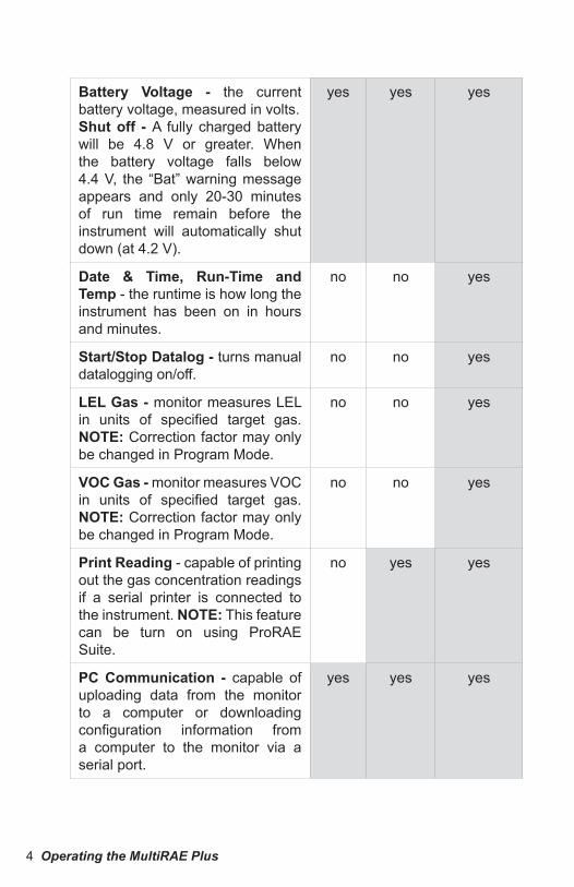
4 Operating the MultiRAE Plus
Battery Voltage - the current battery voltage, measured in volts.Shut off - A fully charged battery will be 4.8 V or greater. When the battery voltage falls below 4.4 V, the “Bat” warning message appears and only 20-30 minutes of run time remain before the instrument will automatically shut down (at 4.2 V).
yes yes yes
Date & Time, Run-Time and Temp - the runtime is how long the instrument has been on in hours and minutes.
no no yes
Start/Stop Datalog - turns manual datalogging on/off.
no no yes
LEL Gas - monitor measures LEL in units of specified target gas. NOTE: Correction factor may only be changed in Program Mode.
no no yes
VOC Gas - monitor measures VOC in units of specified target gas. NOTE: Correction factor may only be changed in Program Mode.
no no yes
Print Reading - capable of printing out the gas concentration readings if a serial printer is connected to the instrument. NOTE: This feature can be turn on using ProRAE Suite.
no yes yes
PC Communication - capable of uploading data from the monitor to a computer or downloading configuration information from a computer to the monitor via a serial port.
yes yes yes
Operating the MultiRAE Plus 5
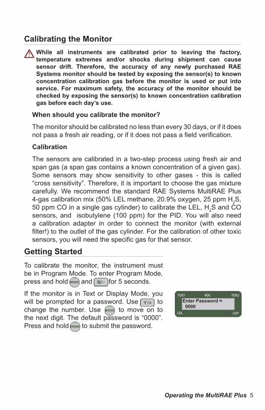
Calibrating the MonitorWhile all instruments are calibrated prior to leaving the factory, temperature extremes and/or shocks during shipment can cause sensor drift. Therefore, the accuracy of any newly purchased RAE Systems monitor should be tested by exposing the sensor(s) to known concentration calibration gas before the monitor is used or put into service. For maximum safety, the accuracy of the monitor should be checked by exposing the sensor(s) to known concentration calibration gas before each day’s use.
When should you calibrate the monitor?
The monitor should be calibrated no less than every 30 days, or if it does not pass a fresh air reading, or if it does not pass a field verification.
Calibration
The sensors are calibrated in a two-step process using fresh air and span gas (a span gas contains a known concentration of a given gas). Some sensors may show sensitivity to other gases - this is called “cross sensitivity”. Therefore, it is important to choose the gas mixture carefully. We recommend the standard RAE Systems MultiRAE Plus 4-gas calibration mix (50% LEL methane, 20.9% oxygen, 25 ppm H2S, 50 ppm CO in a single gas cylinder) to calibrate the LEL, H2S and CO sensors, and isobutylene (100 ppm) for the PID. You will also need a calibration adapter in order to connect the monitor (with external filter!) to the outlet of the gas cylinder. For the calibration of other toxic sensors, you will need the specific gas for that sensor.
Enter Password = 0000
Getting StartedTo calibrate the monitor, the instrument must be in Program Mode. To enter Program Mode, press and hold M and [N/-] for 5 seconds.
If the monitor is in Text or Display Mode, you will be prompted for a password. Use [Y/+] to change the number. Use M to move on to the next digit. The default password is “0000”. Press and hold M to submit the password.

6 Operating the MultiRAE Plus
Span Gas CalibrationTo complete step two of calibration, a Span Gas Calibration must be performed for each sensor.
The instructions below are for a standard confined space entry instrument utilizing CO, H2S, LEL, Oxygen sensors.
For this calibration you will need the standard RAE Systems MultiRAE Plus 4-gas calibration mix (50% LEL methane, 20.9% oxygen, 25 ppm H2S, 50 ppm CO in a single gas cylinder). For the calibration of other toxic sensors, or to calibrate a single sensor, please go to the Program Mode section of this manual.
Fresh Air CalibrationThe first step of calibration is a Fresh Air Calibration:
Calibrate Monitor?
Press [Y/+] .
Fresh Air Calibration?
Press [Y/+] .
The monitor will cycle through each sensor. When the process is complete, the display will read, “Zero Cal Complete!”.
Zero Organic Filters for Zeroing PIDUse an optional external zero organic filter (P/N 008-3024-000, 3-pack) when the ambient air may be contaminated with hydrocarbons.
Attach the filter to the MultiRAE Plus during fresh air calibration. The filter can be used up to 20 times before disposing. This filter removes most heavier organic and inorganic compounds, but may not completely remove lighter compounds such as methane, propane, and CO.
Fresh Air Calibration?
Calibrate Monitor?

Operating the MultiRAE Plus 7
Multiple Sensor CalibrationPress [Y/+] .
The monitor will assume you want to calibrate the CO, H2S, LEL and Oxygen sensors.
Press [Y/+] .
Apply the RAE Systems 4-gas span gas mixture and start the gas flow.
Multiple Sensor Calibration?
CO --- H2SLEL OXY
Span Cal done!Turn off Gas!
Turn off the gas flow and disconnect the calibration adapter from the monitor. If calibration fails, an error message appears instead. Refer to Troubleshooting: “Calibration Error Message” on page 38.
NOTE: If calibration is accidentally started and gas has run out or has been disconnected, press M repeatedly. Calibration will stop and revert back to the previous calibration values.
Calibrating the PID SensorThe single sensor method used to calibrate the PID can also be used to calibrate single toxic sensors. For the PID, use isobutylene (100ppm) span gas. For other toxic sensors, use the appropriate gas, e.g., ammonia sensor - use ammonia gas, etc.
The 60-second countdown timer appears.
“Span Cal Done! Turn Off Gas” message appears. The readings should be very close to the span gas values shown on the gas cylinder.
8 Operating the MultiRAE Plus
Calibration Time Stamp
A time stamp is created and stored each time a sensor calibration is performed, which is included in the datalog report.
Press M twice to exit calibration mode and return to the main display.
NOTE: Residual gas may linger on the sensors for up to 60 seconds.
If the sensors do not return to zero, repeat fresh air calibration.
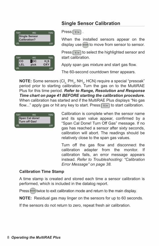
Single Sensor CalibrationPress [Y/+] .
When the installed sensors appear on the display use M to move from sensor to sensor.
Press [Y/+] to select the highlighted sensor and start calibration.
Apply span gas mixture and start gas flow.
The 60-second countdown timer appears.
CO █OC H2SLEL pick OXY
Single Sensor Calibration?
Span Cal done!Turn off Gas!
NOTE: Some sensors (Cl2, PH3, NH3, HCN) require a special “presoak” period prior to starting calibration. Turn the gas on to the MultiRAE Plus for this time period. Refer to Range, Resolution and Response Time chart on page 41 BEFORE starting the calibration procedure. When calibration has started and if the MultiRAE Plus displays “No gas flow...” apply gas or hit any key to start. Press [Y/+] to start calibration.
Calibration is complete when the sensor name and its span value appear, confirmed by a “Span Cal Done! Turn Off Gas” message. If no gas has reached a sensor after sixty seconds, calibration will abort. The readings should be relatively close to the span gas values.
Turn off the gas flow and disconnect the calibration adapter from the monitor. If calibration fails, an error message appears instead. Refer to Troubleshooting: “Calibration Error Message” on page 38.
Operating the MultiRAE Plus 9
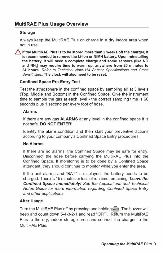
MultiRAE Plus Usage OverviewStorage
Always keep the MultiRAE Plus on charge in a dry indoor area when not in use.
If the MultiRAE Plus is to be stored more than 2 weeks off the charger, it is recommended to remove the Li-ion or NiMH battery. Upon reinstalling the battery, it will need a complete charge and some sensors (like NO and NH3) may require time to warm up, anywhere from 20 minutes to 24 hours. Refer to Technical Note-114 Sensor Specifications and Cross Sensitivities. The clock will also need to be reset.
Confined Space Pre-Entry Test
Test the atmosphere in the confined space by sampling air at 3 levels (Top, Middle and Bottom) in the Confined Space. Give the instrument time to sample the gas at each level - the correct sampling time is 60 seconds plus 1 second per every foot of hose.
Alarms
If there are any gas ALARMS at any level in the confined space it is not safe. DO NOT ENTER!
Identify the alarm condition and then start your preventive actions according to your company’s Confined Space Entry procedures.
No Alarms
If there are no alarms, the Confined Space may be safe for entry. Disconnect the hose before carrying the MultiRAE Plus into the Confined Space. If monitoring is to be done by a Confined Space attendant, they should continue to monitor while you enter the area.
If the unit alarms and “BAT” is displayed, the battery needs to be charged. There is 15 minutes or less of run time remaining. Leave the Confined Space immediately! See the Applications and Technical Notes Guide for more information regarding Confined Space Entry and other applications.
After Usage
Turn the MultiRAE Plus off by pressing and holding M . The buzzer will beep and count down 5-4-3-2-1 and read “OFF”. Return the MultiRAE Plus to the dry, indoor storage area and connect the charger to the MultiRAE Plus.
10 Operating the MultiRAE Plus
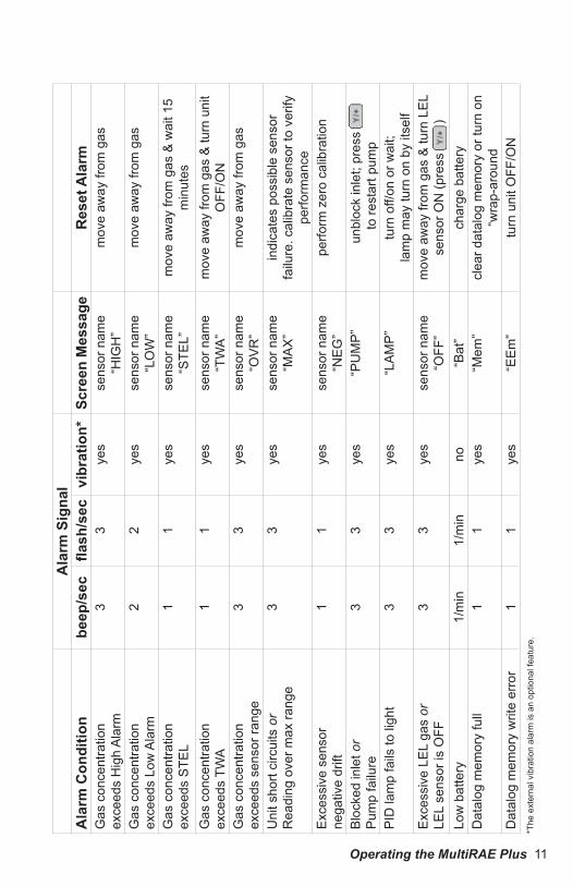
Alarm SignalsWhen an alarm condition occurs, the monitor will provide audible and visual alarms to alert users of unsafe conditions. Refer to the Alarm Signals table on page 11 for a complete list of alarm conditions.
The alarm signals are disabled while in the following modes: Communicate with PC, Print Reading, Calibrate Monitor. To reduce the risk of exposure to hazardous atmospheres, use these modes only in an area known to be non-hazardous.
The alarm system can be set up in one of two ways:
Auto Reset Alarm (default): The alarm signals automatically reset when the alarm condition is no longer present. NOTE: Not all alarm conditions have this option.
Latched Alarm: The alarm signal remains on even when the alarm condition is no longer present; press [Y/+] to acknowledge and reset alarm signals.
Testing Alarm Signals
Press [Y/+] . If functional, the buzzer will beep once and the backlight will flash once.
Operating the MultiRAE Plus 11
Ala
rm S
igna
lA
larm
Con
ditio
nbe
ep/s
ecfla
sh/s
ecvi
brat
ion*
Scre
en M
essa
geR
eset
Ala
rmG
as c
once
ntra
tion
exce
eds
Hig
h A
larm
33
yes
sens
or n
ame
“HIG
H”
mov
e aw
ay fr
om g
as
Gas
con
cent
ratio
nex
ceed
s Lo
w A
larm
22
yes
sens
or n
ame
“LO
W”
mov
e aw
ay fr
om g
as
Gas
con
cent
ratio
nex
ceed
s S
TEL
11
yes
sens
or n
ame
“STE
L”m
ove
away
from
gas
& w
ait 1
5 m
inut
esG
as c
once
ntra
tion
exce
eds
TWA
11
yes
sens
or n
ame
“TW
A”
mov
e aw
ay fr
om g
as &
turn
uni
t O
FF/O
NG
as c
once
ntra
tion
exce
eds
sens
or ra
nge
33
yes
sens
or n
ame
“OV
R”
mov
e aw
ay fr
om g
as
Uni
t sho
rt ci
rcui
ts o
rR
eadi
ng o
ver m
ax ra
nge
33
yes
sens
or n
ame
“MA
X”
indi
cate
s po
ssib
le s
enso
r fa
ilure
. cal
ibra
te s
enso
r to
verif
y pe
rform
ance
Exc
essi
ve s
enso
rne
gativ
e dr
ift1
1ye
sse
nsor
nam
e“N
EG
”pe
rform
zer
o ca
libra
tion
Blo
cked
inle
t or
Pum
p fa
ilure
33
yes
“PU
MP
”un
bloc
k in
let;
pres
s to
rest
art p
ump
PID
lam
p fa
ils to
ligh
t3
3ye
s“L
AM
P”
turn
off/
on o
r wai
t;la
mp
may
turn
on
by it
self
Exc
essi
ve L
EL
gas
orLE
L se
nsor
is O
FF3
3ye
sse
nsor
nam
e“O
FF”
mov
e aw
ay fr
om g
as &
turn
LE
L se
nsor
ON
(pre
ss
)
Low
bat
tery
1/m
in1/
min
no“B
at”
char
ge b
atte
ryD
atal
og m
emor
y fu
ll1
1ye
s“M
em”
clea
r dat
alog
mem
ory
or tu
rn o
n “w
rap-
arou
ndD
atal
og m
emor
y w
rite
erro
r1
1ye
s“E
Em
”tu
rn u
nit O
FF/O
N*T
he e
xter
nal v
ibra
tion
alar
m is
an
optio
nal f
eatu
re.
12 Operating the MultiRAE Plus
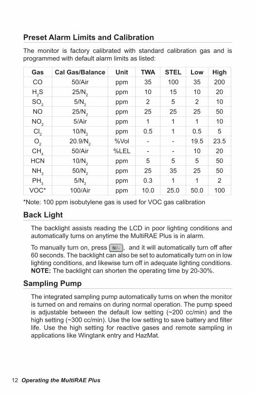
Preset Alarm Limits and CalibrationThe monitor is factory calibrated with standard calibration gas and is programmed with default alarm limits as listed:
Gas Cal Gas/Balance Unit TWA STEL Low HighCO 50/Air ppm 35 100 35 200H2S 25/N2 ppm 10 15 10 20SO2 5/N2 ppm 2 5 2 10NO 25/N2 ppm 25 25 25 50NO2 5/Air ppm 1 1 1 10Cl2 10/N2 ppm 0.5 1 0.5 5O2 20.9/N2 %Vol - - 19.5 23.5
CH4 50/Air %LEL - - 10 20HCN 10/N2 ppm 5 5 5 50NH3 50/N2 ppm 25 35 25 50PH3 5/N2 ppm 0.3 1 1 2
VOC* 100/Air ppm 10.0 25.0 50.0 100
*Note: 100 ppm isobutylene gas is used for VOC gas calibration
Back LightThe backlight assists reading the LCD in poor lighting conditions and automatically turns on anytime the MultiRAE Plus is in alarm.
To manually turn on, press [N/-] , and it will automatically turn off after 60 seconds. The backlight can also be set to automatically turn on in low lighting conditions, and likewise turn off in adequate lighting conditions. NOTE: The backlight can shorten the operating time by 20-30%.
Sampling PumpThe integrated sampling pump automatically turns on when the monitor is turned on and remains on during normal operation. The pump speed is adjustable between the default low setting (~200 cc/min) and the high setting (~300 cc/min). Use the low setting to save battery and filter life. Use the high setting for reactive gases and remote sampling in applications like Wingtank entry and HazMat.
Operating the MultiRAE Plus 13
The monitor can detect any obstructions in the external filter that causes a pump stall. The alarm will activate and a “Pump” error message will appear. To acknowledge the pump stall, press [Y/+] to start the pump again.
Refer to Pump Stall on page 29 for details on how to adjust the pump stall threshold for either the high or low settings.
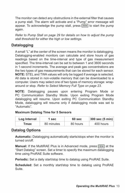
DataloggingA small “L” at the center of the screen means the monitor is datalogging. Datalogging-enabled monitors can calculate and store hours of gas readings based on the time-interval and type of gas measurement specified. The time-interval can be set to between 1 and 3600 seconds in 1-second increments. The average and peak gas concentrations are the two types of gas measurements that can be stored for each sensor. NOTE: STEL and TWA values will only be logged if average is selected. All data is stored in non-volatile memory that can be downloaded to a computer. Users may select one of two types of memory storage: wrap-around or stop. Refer to Select Memory Full Type on page 23.
NOTE: Datalogging pauses upon entering Program Mode or PC Communication Standby Mode. Upon exiting Program Mode datalogging will resume. Upon exiting PC Communication Standby Mode, datalogging will resume only if datalogging mode was set to “Automatic”.
Maximum Datalog Time for 5 Sensors
Log Interval 1 sec 60 sec 300 sec (5 min)Tmax 80 minutes 80 hours 400 hours
Datalog OptionsAutomatic: Datalogging automatically starts/stops when the monitor is turned on/off.
Manual: If the MultiRAE Plus is in Advanced mode, press [Y/+] at the “Start Datalog” screen. Set a timer to specify the maximum datalogging time using ProRAE Suite software.
Periodic: Set a daily start/stop time to datalog using ProRAE Suite.
Scheduled: Set a monthly start/stop time to datalog using ProRAE Suite.
14 Operating the MultiRAE Plus
Charging the Battery PackTo charge the battery pack plug the transformer supplied with the monitor into the power jack on the monitor.
When a Li-Ion or NiMH battery pack is installed, charging automatically begins. The LED appears red during charging, and once the battery is fully charged, the LED turns green. The display also indicates the charge status. A completely drained battery pack charges to full capacity in less than 10 hours. When the “Bat” message appears on the LCD, the battery pack needs to be recharged.
NOTE: A fully charged battery pack will switch to trickle charge to maintain battery life. Repeatedly turning the power to the transformer on and off will reset the charge and possibly burn out the battery.
To change the battery pack or to use the alkaline battery adapter, refer to Replacing the Battery Pack or Emergency Alkaline Battery Adapter on page 32.
If the MultiRAE Plus is to be stored more than 2 weeks off the charger, it is recommended to remove the Li-ion or NiMH battery.
NiMH Battery Pack Deep Discharge When RechargingWhen charging a NiMH battery pack, note that the display will show “Start battery deep discharge?” when you initiate charging. If you do not press any button for 10 seconds, it will start charging automatically. If you press , it will perform the discharging process and then automatically begin charging the battery. If you press , it will only charge the battery.
Accessories 15
External FiltersThe external filter is a PTFE (Teflon®) membrane with a 0.2 micron pore that reduces the amount of liquid and dust that can contaminate the sensor. Using the external filter prolongs sensor and pump life.
Change the external filter whenever it becomes discolored, clogged with particles, or draws in liquid.
NOTE: Do not use the external filter when calibrating reactive gases. Instead, use the High Pump Speed setting and a short Teflon® tube. Although this shortens battery life, it provides a faster response.
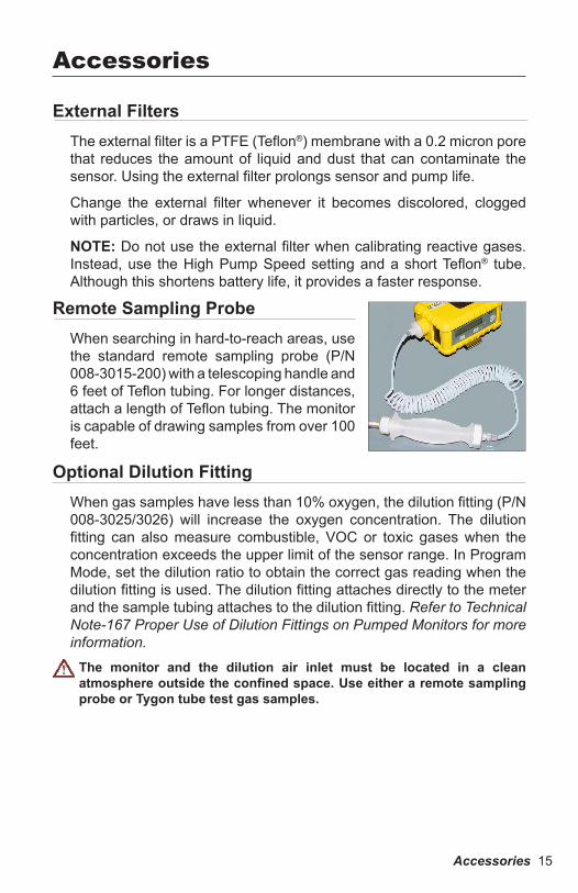
Remote Sampling ProbeWhen searching in hard-to-reach areas, use the standard remote sampling probe (P/N 008-3015-200) with a telescoping handle and 6 feet of Teflon tubing. For longer distances, attach a length of Teflon tubing. The monitor is capable of drawing samples from over 100 feet.
Accessories
Optional Dilution Fitting When gas samples have less than 10% oxygen, the dilution fitting (P/N 008-3025/3026) will increase the oxygen concentration. The dilution fitting can also measure combustible, VOC or toxic gases when the concentration exceeds the upper limit of the sensor range. In Program Mode, set the dilution ratio to obtain the correct gas reading when the dilution fitting is used. The dilution fitting attaches directly to the meter and the sample tubing attaches to the dilution fitting. Refer to Technical Note-167 Proper Use of Dilution Fittings on Pumped Monitors for more information.
The monitor and the dilution air inlet must be located in a clean atmosphere outside the confined space. Use either a remote sampling probe or Tygon tube test gas samples.

16 Accessories
Calibration AdapterThe calibration adapter is a 6-inch Tygon tube with a male Luer connector on the end. During calibration, connect one end of the tube to the external filter (on the monitor) and the other end to the calibration gas.
Alternatively, the calibration gas can be sampled from:
an optional Tedlar gas bag (P/N 500-0003-000) filled with calibration gas,
Accessories 17
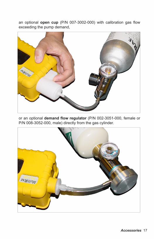
an optional open cup (P/N 007-3002-000) with calibration gas flow exceeding the pump demand,
or an optional demand flow regulator (P/N 002-3051-000, female or P/N 008-3052-000, male) directly from the gas cylinder.
18 Program Mode
In addition to calibration, authorized users may change the monitor settings to their requirements using the Programming Mode.
NOTE: Monitoring gas concentrations continues during Programming Mode, but pauses during Calibration. Datalogging also pauses during Programming Mode, but resumes when programming is finished.
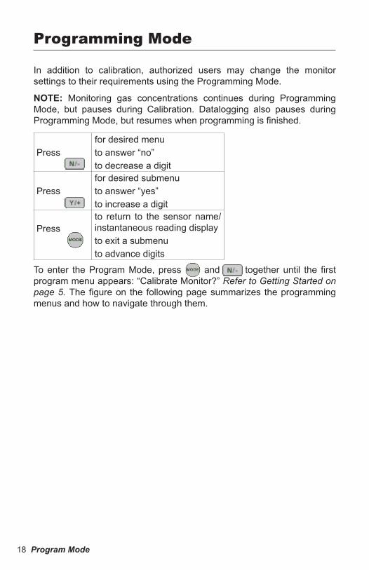
Press for desired menuto answer “no”to decrease a digit
Pressfor desired submenuto answer “yes”to increase a digit
Pressto return to the sensor name/instantaneous reading displayto exit a submenuto advance digits
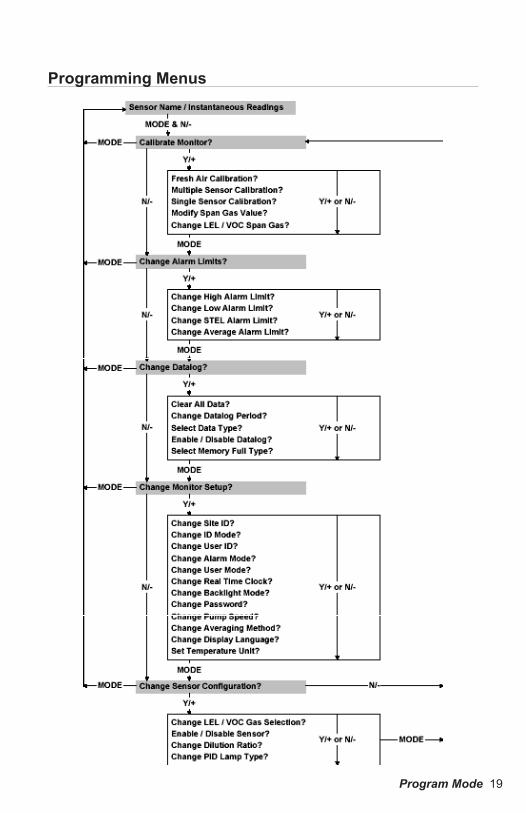
To enter the Program Mode, press M and [N/-] together until the first program menu appears: “Calibrate Monitor?” Refer to Getting Started on page 5. The figure on the following page summarizes the programming menus and how to navigate through them.
Programming Mode
Program Mode 19
Programming Menus
20 Program Mode
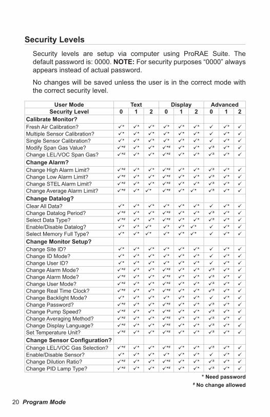
Security LevelsSecurity levels are setup via computer using ProRAE Suite. The default password is: 0000. NOTE: For security purposes “0000” always appears instead of actual password.
No changes will be saved unless the user is in the correct mode with the correct security level.
User Mode Text Display AdvancedSecurity Level 0 1 2 0 1 2 0 1 2
Calibrate Monitor?Fresh Air Calibration? * * * * * * * Multiple Sensor Calibration? * * * * * * * Single Sensor Calibration? * * * * * * * Modify Span Gas Value? *# * * *# * * # * Change LEL/VOC Span Gas? *# * * *# * * # *
Change Alarm?Change High Alarm Limit? *# * * *# * * # * Change Low Alarm Limit? *# * * *# * * # * Change STEL Alarm Limit? *# * * *# * * # * Change Average Alarm Limit? *# * * *# * * # *
Change Datalog?Clear All Data? * * * * * * * Change Datalog Period? *# * * *# * * # * Select Data Type? *# * * *# * * # * Enable/Disable Datalog? * * * * * * * Select Memory Full Type? * * * * * * *
Change Monitor Setup?Change Site ID? * * * * * * * Change ID Mode? * * * * * * * Change User ID? * * * * * * * Change Alarm Mode? *# * * *# * * # * Change Alarm Mode? *# * * *# * * # * Change User Mode? *# * * *# * * # * Change Real Time Clock? *# * * *# * * # * Change Backlight Mode? * * * * * * * Change Password? *# * * *# * * # * Change Pump Speed? *# * * *# * * # * Change Averaging Method? *# * * *# * * # * Change Display Language? *# * * *# * * # * Set Temperature Unit? *# * * *# * * # *
Change Sensor Configuration?Change LEL/VOC Gas Selection? *# * * *# * * # * Enable/Disable Sensor? * * * * * * * Change Dilution Ratio? *# * * *# * * # * Change PID Lamp Type? *# * * *# * * # *
* Need password# No change allowed

Program Mode 21
Calibrate MonitorFresh Air Calibration? Refer to Calibrating the Monitor on page 5.
Multiple Sensor Calibration? Refer to Calibrating the Monitor.
Single Sensor Calibration? Refer to Calibrating the Monitor.
Oxygen Sensor Calibration: The oxygen sensor calibration is slightly different from other sensors; span calibration at 20.9% O2 is perormed during fresh air calibration. During single sensor calibration, the oxygen sensor can be calibrated to 0% O2 with pure nitrogen gas, by pressing [Y/+] when asked “0%? Oxygen?” To calibrate at a different concentration specified in Modify Span Gas Value, press [N/-].
NOTE: After a single sensor oxygen calibration, perform fresh air calibration to ensure the oxygen sensor is calibrated correctly.
Modify Span Gas Value?
The span gas is the second point of reference for calibration. Users may modify the span values of the standard calibration gases to use other calibration gases. However, DO NOT modify the span values when using the RAE Systems calibration gas supplied with the monitor.
Change LEL/VOC Span Gas?
Change the type of calibration gas from methane (LEL) and isobutylene (VOC) to be used as the span gas during LEL or VOC gas calibration. However, DO NOT modify the span gases when using the RAE Systems calibration gas supplied with the monitor.
Change Alarm LimitsUsers may change the alarm limits for each sensor. Use [N/-] to cycle through the submenu options. Press [Y/+] to enter a submenu. To modify the limit, use [Y/+] and [N/-] to change the value. Use M to move from character to charater.
To escape the submenu without saving changes, press M . To save, press M until “Save?” appears. Press [Y/+] to save changes, otherwise press [N/-] to discard changes.
Change High Alarm Limit?
Change Low Alarm Limit?
Change STEL Alarm Limit? (Short Term Exposure Limit)
Change Average Alarm Limit? (TWA – Time Weighted Average)
22 Program Mode
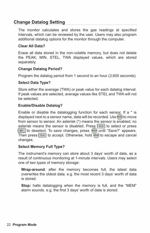
Change Datalog SettingThe monitor calculates and stores the gas readings at specified intervals, which can be reviewed by the user. Users may also program additional datalog options for the monitor through the computer.
Clear All Data?
Erase all data stored in the non-volatile memory, but does not delete the PEAK, MIN, STEL, TWA displayed values, which are stored separately.
Change Datalog Period?
Program the datalog period from 1 second to an hour (3,600 seconds).
Select Data Type?
Store either the average (TWA) or peak value for each datalog interval. If peak values are selected, average values like STEL and TWA will not be selected.
Enable/Disable Datalog?
Enable or disable the datalogging function for each sensor. If a * is displayed next to a sensor name, data will be recorded. Use M to move from sensor to sensor. An asterisk (*) means the sensor is enabled; no asterisk means the sensor is disabled. Press [Y/+] to select or press [N/-] to deselect. To save changes, press M until “Save?” appears. Then press [Y/+] to accept. Otherwise, hold M to escape and cancel changes.
Select Memory Full Type?
The instrument’s memory can store about 3 days’ worth of data, as a result of continuous monitoring at 1-minute intervals. Users may select one of two types of memory storage:
Wrap-around: after the memory becomes full, the latest data overwrites the oldest data. e.g. the most recent 3 days’ worth of data is stored.
Stop: halts datalogging when the memory is full, and the “MEM” alarm sounds. e.g. the first 3 days’ worth of data is stored.
Program Mode 23
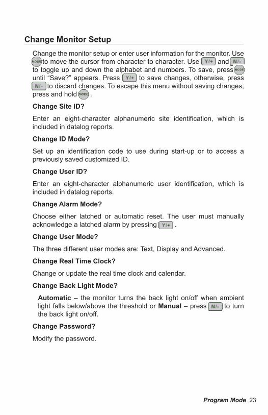
Change Monitor SetupChange the monitor setup or enter user information for the monitor. Use M to move the cursor from character to character. Use [Y/+] and [N/-] to toggle up and down the alphabet and numbers. To save, press M until “Save?” appears. Press [Y/+] to save changes, otherwise, press [N/-] to discard changes. To escape this menu without saving changes, press and hold M .
Change Site ID?
Enter an eight-character alphanumeric site identification, which is included in datalog reports.
Change ID Mode?
Set up an identification code to use during start-up or to access a previously saved customized ID.
Change User ID?
Enter an eight-character alphanumeric user identification, which is included in datalog reports.
Change Alarm Mode?
Choose either latched or automatic reset. The user must manually acknowledge a latched alarm by pressing [Y/+] .
Change User Mode?
The three different user modes are: Text, Display and Advanced.
Change Real Time Clock?
Change or update the real time clock and calendar.
Change Back Light Mode?
Automatic – the monitor turns the back light on/off when ambient light falls below/above the threshold or Manual – press [N/-] to turn the back light on/off.
Change Password?
Modify the password.
24 Program Mode
Change Pump Speed?
Low – (default) use when operating conditions are slow to change; prolongs pump motor life, LEL sensor life and battery run time.
High – use for long lengths of tubing or when rapid changes in input conditions are expected, such as HazMat response or when used for measuring heavy, low vapor pressure compounds like jet fuel.
Change Averaging Method?
Choose: TWA (default) – an eight-hour Time Weighted Average or AVG – the running average
Change Display Language?
Choose English or Spanish.
Set Temperature Unit?
Choose Celsius or Fahrenheit to measure temperature.
Change Sensor ConfigurationChange LEL/VOC Gas Selection?
Choose an LEL or VOC gas listed in the monitor to calculate its correction factor relative to the LEL or VOC calibration gas. Refer to Correction Factors on page 26. The correction factor allows the unit to display the equivalent concentration of the selected LEL or VOC gas. To create a custom factor for a specific gas or mixture of gases, modify the relative correction factor to increase or decrease the gas reading.
Enable/Disable Sensor?
Enable or disable sensor(s); a disabled sensor will not measure or display the gas concentration. Use if a sensor has failed or is providing erroneous readings. Use M to move from sensor to sensor. An asterisk (*) means the sensor is enabled; likewise, no (*) means the sensor is disabled. Press [Y/+] to select or press [N/-] to deselect. To save changes, press M until “Save?” appears. Then press [Y/+] to accept. Otherwise, hold M to escape and cancel changes.
Program Mode 25
Change Dilution Ratio?
Attach an optional dilution fitting on the gas inlet port to dilute the gas sample. Enter a dilution ratio (from 1 to 10) to compensate the reading for the actual gas concentration.
Change PID Lamp Type?
This only applies to PID monitors. The PID sensor can utilize either a 10.6 eV or an 11.7eV UV. Since each lamp type has a different correction factor table, it is important to select the correct lamp type.
Correction FactorsVOC and LEL sensors respond to a broad range of gases and show a different sensitivity to different gases; correction factors allow measurement of a specific gas (the measurement gas) while using a different gas for calibration (the calibration gas). The correction factor (CF) for a measurement gas is defined as:
CF = Sensitivity to a Calibration Gas ÷ Sensitivity to a Measurement Gas
To convert the monitor reading of the calibration gas to the true concentration of a measurement gas, use the following equation:
True Concentration (ppm) = CF x Monitor Reading (ppm)
The monitor has three sets of correction factors, one for the LEL and two for the VOC (10.6 eV and 11.7 eV) Each set consists of 20 to 40 different gases. Specify the PID lamp type (e.g. 10.6 eV or 11.7 eV) to access the proper VOC correction factor.
To set up a correction factor, first choose a calibration gas in the Calibrate Monitor program menu and then choose a measurement gas in the Change Sensor Configuration menu. If the calibration gas is different from methane for LEL or isobutylene for PID, then the new CF is calculated and the displayed value will be different from the values in Technical Notes 106 or 156.
NOTE: Correction factors provide an estimate of the measurement gas concentration. For greatest accuracy, it is necessary to calibrate the LEL or VOC sensor directly with the measurement gas.
Refer to Technical Note-106 Correction Factors and/or Technical Note-156 LEL Correction Factors.
26 Diagnostic Mode
The monitor is equipped with a diagnostic mode that can display critical, low lever parameters to help users identify problems. Refer to Troubleshooting on page 38.
The diagnostic mode allows the user to set several low level parameters which are very critical to the operation of the monitor. Extra care should be taken when setting these low level parameters. If the user is unfamiliar with these parameters and sets them incorrectly, it may cause the monitor to shut down or malfunction. The diagnostic mode should only be used by qualified personnel.
To switch the monitor to diagnostic mode, turn the monitor off.
Press and hold [Y/+] and M together; release both keys when the unit beeps. The monitor is now in diagnostic mode.
Press M until the desired diagnostic parameter appears:
Sensor Name and Raw Sensor ReadingsIf a sensor is programmed and is properly installed, the sensor name should appear. If the sensor name does not appear, then the sensor may be improperly programmed or defective. The raw sensor reading is the uncalibrated output for each sensor. When fresh air is applied, the raw sensor readings should be 200 to 700 for toxic gas and VOC sensors; 100 to 1300 for the LEL sensor; and 1200 to 2300 for the oxygen sensor. When calibration gas is applied, the raw sensor readings should increase or decrease by the amounts listed in Technical Note -123 Special Diagnostic Modes. If the raw sensor readings are outside the normal range or do not change when gas is applied, the sensor or monitor may be defective.
RF Test (Radio Frequency)This feature applies when the monitor is used with the RAELink Remote package. The RF test shows the successful rate of communication.
Adjust Lamp Failure ThresholdIf the lamp physically appears fine, but the “Lamp” error message appears during normal operation, the lamp failure threshold may be set too high.
Diagnostic Mode
Diagnostic Mode 27
To adjust the level:
Turn the monitor on in diagnostic mode and go to the “Lamp = xxx, Fail = yyy +/-” display. (“xxx” is the lamp current reading; “yyy” is the value of the lamp failure threshold.)
Decrease the “yyy” value until it is about 10 counts below the “xxx” value. Press M to exit.
Then press [Y/+] to save changes, or press [N/-] to discard changes.
Battery Type and BiasThe type of battery (Lithium-Ion battery pack, NiMH battery pack, or alkaline battery adapter) used to charge the monitor is displayed. Some toxic gas sensors require a bias voltage of a few hundred millivolts for the sensor to function properly. These include NO and NH3 sensors.
To manually switch the bias voltage supply on, refer to Special Bias Voltage for Toxic Sensors on page 35.
Install a biased sensor in the TOX1 socket. If the bias voltage is switched on, the bias reading should be below 182, otherwise it may be defective.
Show x1 and x10 Range of PID Sensor (PID detectors only)
The PID sensor is connected to two amplifiers with two different gains: unity gain and gain of ten; these are the raw outputs of both amplifiers. When fresh air is applied, both amplifier outputs should be 200 to 500. When a VOC gas is applied, both amplifier outputs should increase; the amount of increase for the unity gain (x1) should be 1/10 of the increase for the gain of ten (x10). If the increase does not agree with the expected value, then the gain switch of the amplifier may be defective.
Display ContrastPress [Y/+] to increase the contrast and [N/-] to decrease the contrast. The LCD contrast bar indicates the current setting. If the display appears to have dark lines, press [Y/+] a few times to see the display more clearly. NOTE: In extreme temperatures, the display may fade or bleed out.
LEL PowerThe top line indicates the instantaneous reading of raw counts from the LEL sensor. The bottom line shows if the LEL sensor is on or off. Press [N/-] to turn the power off, and press [Y/+] to turn the power on.
28 Diagnostic Mode
Clock, Time, Battery, and Temperature This display shows the real time clock, the date, the battery voltage in raw count and temperature sensor reading.
Sensor Expiration DateThe expiration date (month and year) for each installed sensor is based on the manufacturing date and expected life of each sensor. If the current date exceeds the expiration date for any sensor, the performance of the given sensor cannot be guaranteed. It is strongly recommended to replace the sensor immediately to ensure proper operation.
Pump StallThe “Pump = 20/20” reading is the minimum and maximum pump raw count (RC), and “Stall = 40 +/-” is the pump stall threshold. The pump stalls if the maximum raw count reaches the pump stall threshold, which causes the pump to shut off. To determine the pump stall threshold:
[ (max RC when pump is free + max RC when pump is blocked) ] ÷ 2
To adjust the pump stall threshold, press [Y/+] to increase or [N/-] to decrease the numerical value.
Back Light ThresholdAdjust the threshold for the LCD backlight to automatically turn on/off; verify the threshold is 100, which is suitable for most situations.
Serial Number and PumpDisplays the monitor’s serial number and the pump status. If a pump is installed and a pump speed control circuit is available, toggle the display “Pump=Low/High” by pressing [N/-] . NOTE: Changes made are only for testing the pump condition and are not saved to the nonvolatile memory. Refer to Change Pump Speed on page 25.
Battery Duration TimeUse to test battery life and displays the last run time before the unit turned itself off due to low battery.
Communicate with PCConnect monitor to a personal computer to upload a configuration file or download stored data.
Maintenance 29
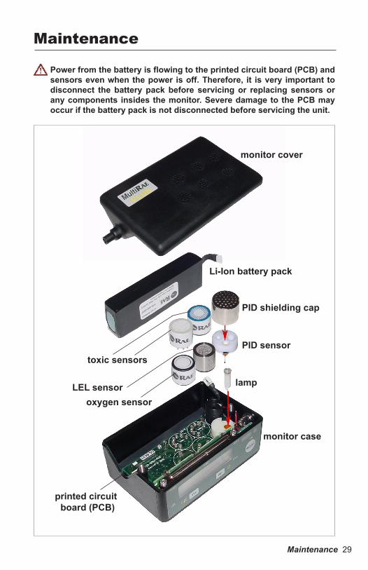
Power from the battery is flowing to the printed circuit board (PCB) and sensors even when the power is off. Therefore, it is very important to disconnect the battery pack before servicing or replacing sensors or any components insides the monitor. Severe damage to the PCB may occur if the battery pack is not disconnected before servicing the unit.
Maintenance
monitor cover
Li-Ion battery pack
PID shielding cap
PID sensor
lamp
monitor case
toxic sensors
LEL sensoroxygen sensor
printed circuit board (PCB)
30 Maintenance
Li-Ion And NiMH Battery PackThe factory supplied Li-Ion and NiMH battery pack is designed to last for 12 or 9 hours, respectively, of normal operation (without alarm or backlight conditions).The rechargeable batteries have a 1-year warranty. Age, ambient temperature, and heavy useage may impact battery life. Battery packs will slowly drain even if the monitor is turned off. If the battery packs have not been charged for 10 days, the battery voltage will be low. It is recommended to fully charge the battery packs (normally, 12 hours) before going into the field, and recharge the battery pack upon returning from the field.
To reduce the risk of ignition of hazardous atmospheres, recharge battery only in areas known to be non-hazardous. Remove and replace battery only in areas known to be non-hazardous. Ne charger les batteries que dans emplacements désignés non dangereux.
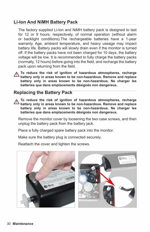
Replacing the Battery PackTo reduce the risk of ignition of hazardous atmospheres, recharge battery only in areas known to be non-hazardous. Remove and replace battery only in areas known to be non-hazardous. Ne charger les batteries que dans emplacements désignés non dangereux.
Remove the monitor cover by loosening the two case screws, and then unplug the battery pack from the battery jack.
Place a fully charged spare battery pack into the monitor.
Make sure the battery plug is connected securely.
Reattach the cover and tighten the screws.
Maintenance 31
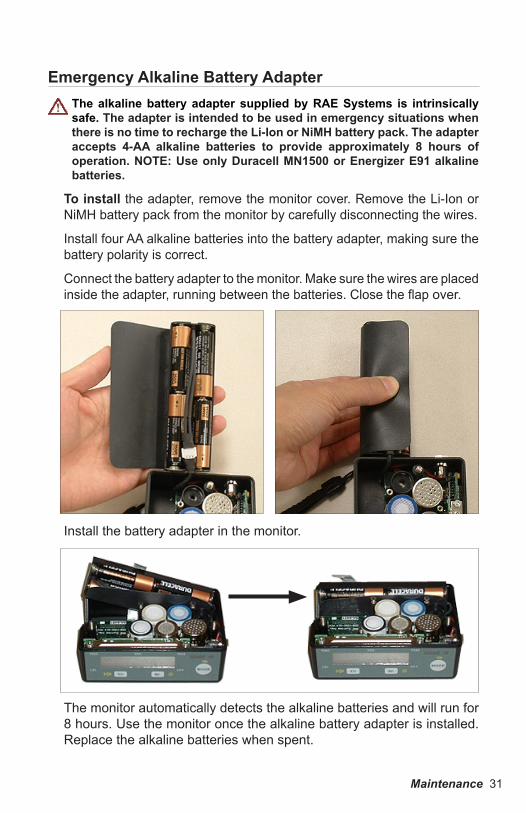
Emergency Alkaline Battery AdapterThe alkaline battery adapter supplied by RAE Systems is intrinsically safe. The adapter is intended to be used in emergency situations when there is no time to recharge the Li-Ion or NiMH battery pack. The adapter accepts 4-AA alkaline batteries to provide approximately 8 hours of operation. NOTE: Use only Duracell MN1500 or Energizer E91 alkaline batteries.
To install the adapter, remove the monitor cover. Remove the Li-Ion or NiMH battery pack from the monitor by carefully disconnecting the wires.
Install four AA alkaline batteries into the battery adapter, making sure the battery polarity is correct.
Connect the battery adapter to the monitor. Make sure the wires are placed inside the adapter, running between the batteries. Close the flap over.
Install the battery adapter in the monitor.
The monitor automatically detects the alkaline batteries and will run for 8 hours. Use the monitor once the alkaline battery adapter is installed. Replace the alkaline batteries when spent.
32 Maintenance
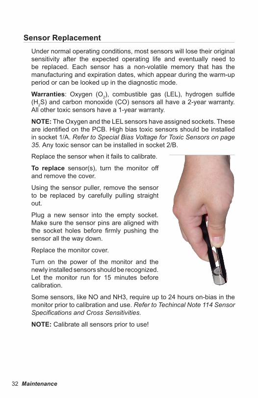
Sensor ReplacementUnder normal operating conditions, most sensors will lose their original sensitivity after the expected operating life and eventually need to be replaced. Each sensor has a non-volatile memory that has the manufacturing and expiration dates, which appear during the warm-up period or can be looked up in the diagnostic mode.
Warranties: Oxygen (O2), combustible gas (LEL), hydrogen sulfide (H2S) and carbon monoxide (CO) sensors all have a 2-year warranty. All other toxic sensors have a 1-year warranty.
NOTE: The Oxygen and the LEL sensors have assigned sockets. These are identified on the PCB. High bias toxic sensors should be installed in socket 1/A. Refer to Special Bias Voltage for Toxic Sensors on page 35. Any toxic sensor can be installed in socket 2/B.
Replace the sensor when it fails to calibrate.
To replace sensor(s), turn the monitor off and remove the cover.
Using the sensor puller, remove the sensor to be replaced by carefully pulling straight out.
Plug a new sensor into the empty socket. Make sure the sensor pins are aligned with the socket holes before firmly pushing the sensor all the way down.
Replace the monitor cover.
Turn on the power of the monitor and the newly installed sensors should be recognized. Let the monitor run for 15 minutes before calibration.
Some sensors, like NO and NH3, require up to 24 hours on-bias in the monitor prior to calibration and use. Refer to Techincal Note 114 Sensor Specifications and Cross Sensitivities.
NOTE: Calibrate all sensors prior to use!

Maintenance 33
CO Sensor Charcoal FiltersCO sensors can be sensitive to hydrocarbons. To reduce or eliminate this cross sensitivity, a charcoal filter is installed in the gas plate above the CO sensor. The charcoal filter removes organic vapor cross-sensitivity and will last 4-6 weeks under normal operation conditions before it needs to be replaced. However, if the monitor is exposed to high concentrations of VOC gases, the carbon filter needs to be replaced more frequently. (P/N 008-3006-005, 5-pack; keep unused filters sealed during storage.)
Refer to Technical Note-121 CO Sensor Cross-Sensitivity and Removal with Charcoal Filter for cross-sensitivity data.
The carbon filter used for CO sensors may lower the reading if used on other sensors. Remove the filter if another sensor is replacing a CO sensor in the monitor.
place carbon filter above the CO sensor in either position, not both
34 Maintenance
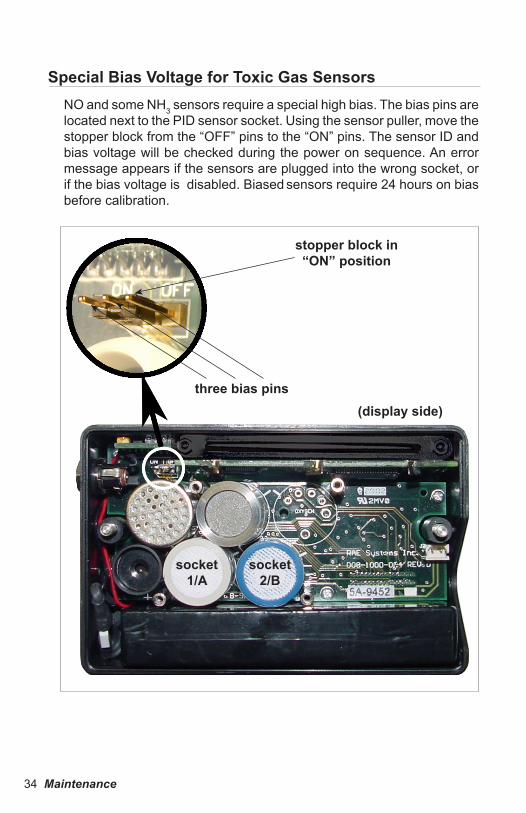
Special Bias Voltage for Toxic Gas SensorsNO and some NH3 sensors require a special high bias. The bias pins are located next to the PID sensor socket. Using the sensor puller, move the stopper block from the “OFF” pins to the “ON” pins. The sensor ID and bias voltage will be checked during the power on sequence. An error message appears if the sensors are plugged into the wrong socket, or if the bias voltage is disabled. Biased sensors require 24 hours on bias before calibration.
three bias pins
stopper block in “ON” position
(display side)
socket1/A
socket2/B
Maintenance 35
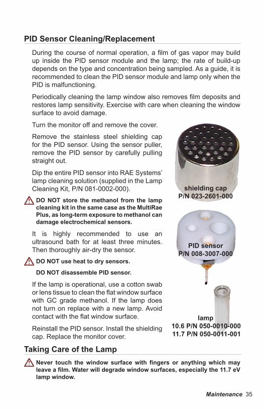
PID Sensor Cleaning/ReplacementDuring the course of normal operation, a film of gas vapor may build up inside the PID sensor module and the lamp; the rate of build-up depends on the type and concentration being sampled. As a guide, it is recommended to clean the PID sensor module and lamp only when the PID is malfunctioning.
Periodically cleaning the lamp window also removes film deposits and restores lamp sensitivity. Exercise with care when cleaning the window surface to avoid damage.
Turn the monitor off and remove the cover.
shielding capP/N 023-2601-000
PID sensorP/N 008-3007-000
lamp10.6 P/N 050-0010-00011.7 P/N 050-0011-001
Remove the stainless steel shielding cap for the PID sensor. Using the sensor puller, remove the PID sensor by carefully pulling straight out.
Dip the entire PID sensor into RAE Systems’ lamp cleaning solution (supplied in the Lamp Cleaning Kit, P/N 081-0002-000).
DO NOT store the methanol from the lamp cleaning kit in the same case as the MultiRae Plus, as long-term exposure to methanol can damage electrochemical sensors.
It is highly recommended to use an ultrasound bath for at least three minutes. Then thoroughly air-dry the sensor.
DO NOT use heat to dry sensors.
DO NOT disassemble PID sensor.
If the lamp is operational, use a cotton swab or lens tissue to clean the flat window surface with GC grade methanol. If the lamp does not turn on replace with a new lamp. Avoid contact with the flat window surface.
Reinstall the PID sensor. Install the shielding cap. Replace the monitor cover.
Taking Care of the LampNever touch the window surface with fingers or anything which may leave a film. Water will degrade window surfaces, especially the 11.7 eV lamp window.
36 Maintenance
pump
cover
The 10.6 eV PID lamp has a 1-year warranty. The “Lamp” error is an indication of a problem with the lamp current. A dirty or contaminated sensor often causes high readings of the VOC sensor. A weak or inoperative lamp often causes low readings or no response to test gas. If the UV lamp is on while the error message persists, then it is necessary to adjust the lamp threshold. Refer to Adjust Lamp Failure Threshold on page 27.
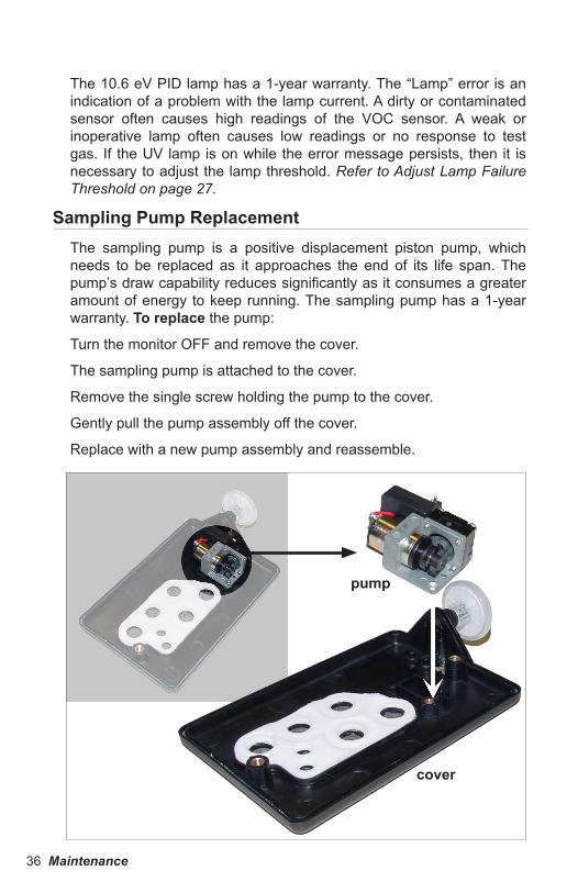
Sampling Pump ReplacementThe sampling pump is a positive displacement piston pump, which needs to be replaced as it approaches the end of its life span. The pump’s draw capability reduces significantly as it consumes a greater amount of energy to keep running. The sampling pump has a 1-year warranty. To replace the pump:
Turn the monitor OFF and remove the cover.
The sampling pump is attached to the cover.
Remove the single screw holding the pump to the cover.
Gently pull the pump assembly off the cover.
Replace with a new pump assembly and reassemble.
Troubleshooting 37
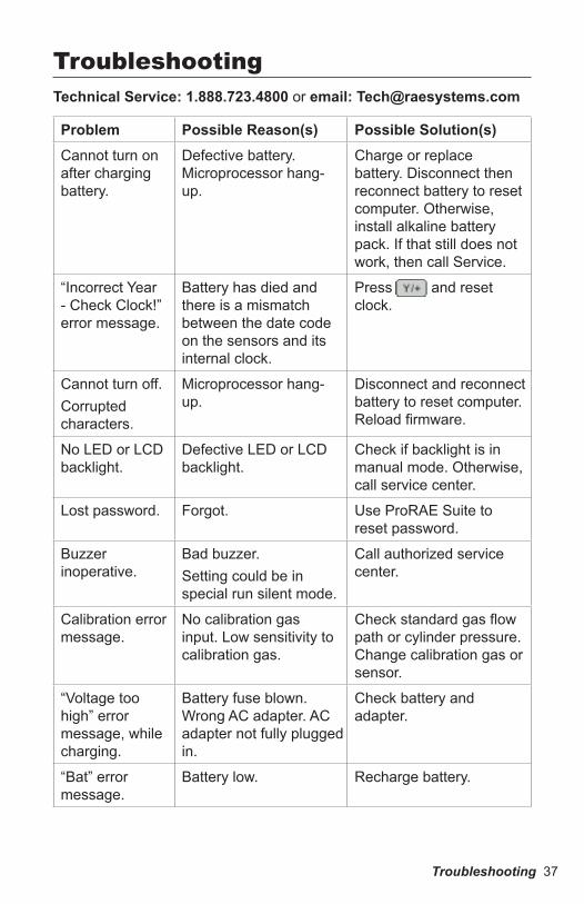
TroubleshootingTechnical Service: 1.888.723.4800 or email: [email protected]
Problem Possible Reason(s) Possible Solution(s)Cannot turn on after charging battery.
Defective battery. Microprocessor hang-up.
Charge or replace battery. Disconnect then reconnect battery to reset computer. Otherwise, install alkaline battery pack. If that still does not work, then call Service.
“Incorrect Year - Check Clock!” error message.
Battery has died and there is a mismatch between the date code on the sensors and its internal clock.
Press [Y/+] and reset clock.
Cannot turn off. Corrupted characters.
Microprocessor hang-up.
Disconnect and reconnect battery to reset computer. Reload firmware.
No LED or LCD backlight.
Defective LED or LCD backlight.
Check if backlight is in manual mode. Otherwise, call service center.
Lost password. Forgot. Use ProRAE Suite to reset password.
Buzzer inoperative.
Bad buzzer.Setting could be in special run silent mode.
Call authorized service center.
Calibration error message.
No calibration gas input. Low sensitivity to calibration gas.
Check standard gas flow path or cylinder pressure. Change calibration gas or sensor.
“Voltage too high” error message, while charging.
Battery fuse blown. Wrong AC adapter. AC adapter not fully plugged in.
Check battery and adapter.
“Bat” error message.
Battery low. Recharge battery.
38 Troubleshooting
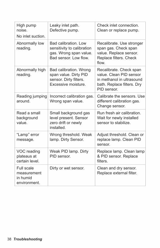
High pump noise.No inlet suction.
Leaky inlet path. Defective pump.
Check inlet connection. Clean or replace pump.
Abnormally low reading.
Bad calibration. Low sensitivity to calibration gas. Wrong span value. Bad sensor. Low flow.
Recalibrate. Use stronger span gas. Check span value. Replace sensor. Replace filters. Check flow.
Abnormally high reading.
Bad calibration. Wrong span value. Dirty PID sensor. Dirty filters. Excessive moisture.
Recalibrate. Check span value. Clean PID sensor in methanol in ultrasound bath. Replace filters. Dry PID sensor.
Reading jumping around.
Incorrect calibration gas. Wrong span value.
Calibrate the sensors. Use different calibration gas. Change sensor.
Read a small background value.
Small background gas level present. Sensor zero drift or newly installed.
Run fresh air calibration. Wait for newly installed sensor to stabilize.
“Lamp” error message.
Wrong threshold. Weak lamp. Dirty Sensor.
Adjust threshold. Clean or replace lamp. Clean PID sensor.
VOC reading plateaus at certain level.
Weak PID lamp. Dirty PID sensor.
Replace lamp. Clean lamp & PID sensor. Replace filters.
Full scale measurement in humid environment.
Dirty or wet sensor. Clean and dry sensor. Replace external filter.
Specifications 39
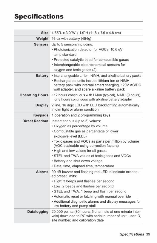
Specifications
Size 4.65”L x 3.0”W x 1.9”H (11.8 x 7.6 x 4.8 cm)Weight 16 oz with battery (454g)
Sensors Up to 5 sensors including:• Photoionization detector for VOCs, 10.6 eV lamp standard• Protected catalytic bead for combustible gases• Interchangeable electrochemical sensors for oxygen and toxic gases (2)
Battery • Interchangeable Li-Ion, NiMH, and alkaline battery packs • Rechargeable units include lithium-ion or NiMH battery pack with internal smart charging, 120V AC/DC wall adapter, and spare alkaline battery pack
Operating Hours • 12 hours continuous with Li-Ion (typical), NiMH (9 hours), or 8 hours continuous with alkaline battery adapter
Display 2 line, 16 digit LCD with LED backlighting automatically in dim light or alarm condition
Keypads 1 operation and 2 programming keysDirect Readout Instantaneous (up to 5) values:
• Oxygen as percentage by volume• Combustible gas as percentage of lower explosive level (LEL)• Toxic gases and VOCs as parts per million by volume (VOC scaleable using correction factors)• High and low values for all gases• STEL and TWA values of toxic gases and VOCs• Battery and shut down voltage• Date, time, elapsed time, temperature
Alarms 90 dB buzzer and flashing red LED to indicate exceed-ed preset limits:• High: 3 beeps and flashes per second• Low: 2 beeps and flashes per second• STEL and TWA: 1 beep and flash per second• Automatic reset or latching with manual override• Additional diagnostic alarms and display messages for low battery and pump stall
Datalogging 20,000 points (80 hours, 5 channels at one minute inter-vals) download to PC with serial number of unit, user ID, site number, and calibration date
40 Specifications
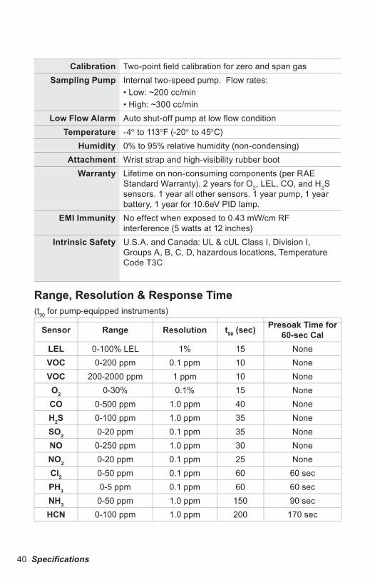
Calibration Two-point field calibration for zero and span gasSampling Pump Internal two-speed pump. Flow rates:
• Low: ~200 cc/min• High: ~300 cc/min
Low Flow Alarm Auto shut-off pump at low flow conditionTemperature -4° to 113°F (-20° to 45°C)
Humidity 0% to 95% relative humidity (non-condensing)Attachment Wrist strap and high-visibility rubber boot
Warranty Lifetime on non-consuming components (per RAE Standard Warranty). 2 years for O2, LEL, CO, and H2S sensors. 1 year all other sensors. 1 year pump, 1 year battery, 1 year for 10.6eV PID lamp.
EMI Immunity No effect when exposed to 0.43 mW/cm RF interference (5 watts at 12 inches)
Intrinsic Safety U.S.A. and Canada: UL & cUL Class I, Division I, Groups A, B, C, D, hazardous locations, Temperature Code T3C
Range, Resolution & Response Time(t90 for pump-equipped instruments)
Sensor Range Resolution t90 (sec) Presoak Time for 60-sec Cal
LEL 0-100% LEL 1% 15 NoneVOC 0-200 ppm 0.1 ppm 10 NoneVOC 200-2000 ppm 1 ppm 10 NoneO2 0-30% 0.1% 15 NoneCO 0-500 ppm 1.0 ppm 40 NoneH2S 0-100 ppm 1.0 ppm 35 NoneSO2 0-20 ppm 0.1 ppm 35 NoneNO 0-250 ppm 1.0 ppm 30 NoneNO2 0-20 ppm 0.1 ppm 25 NoneCl2 0-50 ppm 0.1 ppm 60 60 secPH3 0-5 ppm 0.1 ppm 60 60 secNH3 0-50 ppm 1.0 ppm 150 90 secHCN 0-100 ppm 1.0 ppm 200 170 sec
Service and Repair Record 41
Service and Repair Record
Date Service / Repair Type

RAE Systems World Headquarters3775 N. First St.San Jose, CA 95134-1708 USAPhone: 408.952.8200Toll-Free: 888.723.4800Fax: 408.952.8480E-mail (sales support): [email protected] Site: www.raesystems.com
Technical Support: 408.952.8461 (Mon-Fri, 7AM-5PM, PST)Email: [email protected]
Training: www.raesystems.com/supportEmail: [email protected]
Product Registrationwww.raesystems.com/support/product-registration
RAE Systems EuropeKirstinehøj 23A, DK-2770 Kastrup • DenmarkPhone: +45.8652.5155 • Fax: +45.8652.5177Web: www.raesystems.eu • Email: [email protected]
RAE Systems (Hong Kong) Ltd.Units 1516-18, 15/F, Delta House, 3 On Yiu StreetShatin, N.T. Hong Kong Phone: +852.2669.0828 • Fax: +852.2669.0803Web: www.raesystems.com.hk • Email: [email protected]
RAE Systems Middle EastLOB 7, Ground Floor, Office 19, Jebel Ali Free ZoneDubai, United Arab Emirates Email: [email protected] • Phone: +971.4.887.5562
P/N 008-4022-001 Rev. C February 2010