Multi-NDE Approach for Qualification of Zirconium …no.1 is used for fast termination of nuclear...
8
Multi-NDE Approach for Qualification of Zirconium Alloy Reactivity Mechanism Assemblies for Indian PHWRs R.K. Chaube a , S.Krishna Reddy b , S. Acharya c , P.G. Prasad d , I.S. Reddy e , A.Lakshminarayana f , B.Prahlad g and N. Saibaba h Quality Assurance Group, Nuclear Fuel Complex, Hyderabad-500062, India Email: a [email protected], b [email protected], c [email protected], d [email protected], e [email protected], f [email protected], g [email protected], h [email protected] Key words: Reactivity mechanism assemblies, PHWR, RT, UT, DPT, MSLD. Abstract: Nuclear Fuel Complex (NFC), Hyderabad has manufactured reactivity mechanism assemblies and structural for all the operating Indian pressurized heavy water reactors (PHWRs) and is engaged in the development of these assemblies for the upcoming 700 MWe PHWRs. Being life time core components, structural integrity of all these assemblies, components and weld joint quality needs to be ensured throughout the reactor life. Moreover, these in-core assemblies are being exposed to harsh environment of temperature, vibrations and neutron flux for considerably long period. These assemblies are being fabricated by joining thin wall Zirconium alloy tube to the machined component using high end welding process viz. Electron Beam Welding (EBW) due to its inherent merits such as cleaner process, narrow heat affected zone and extremely low gaseous pick- up. Being intricate in configuration and extremely long length, qualification of these assemblies during fabrication is a challenge. In NFC, integrity of weld joints and assemblies are being ensured by employing multi-NDE techniques such as visual examination, X-ray radiography (RT), ultrasonic testing (UT), dye penetrant test (DPT), mass-spectrometric based leak detection (MSLD). Destructive tests and characterization tools such as tensile test, corrosion test, chemical analysis and optical microscopy are being carried out for evaluating mechanical & metallurgical properties of individual components and weld joints. Generally ultrasonic examination is employed for qualification of ingots, billet stock, tubular components and radiographic examination is carried out for volumetric examination of weld joints. But it is being observed, a few weld joint configurations are not amenable for volumetric examination using radiography (especially for detection of planar defects like lack of penetration, lack of fusion, cracks etc.) due to either complex joint configuration or very high component thickness limiting to the X-ray beam penetration. In such cases ensuring the required soundness of the weld joint is a challenge. Alternately, Ultrasonic method by angle beam contact mode was employed and standardized for qualification of such weld joints which are otherwise not suitable for radiography. MSLD system is used to ensure leak tightness of assemblies, sub-assemblies, weld joint and rolled joints. Functional test like hydrostatic pressure test is carried out to ensure structural integrity. This paper describes the multi-NDE approaches adopted for quality assurance of wide variety of reactivity mechanism assemblies for Indian PHWRs. 1.0 Introduction Reactivity Mechanism assemblies are being used in Pressurized Heavy Water Reactors (PHWRs) for the purposes of reactivity control and monitoring during normal operating condition as well as for shut down and trip the operating reactor as and when situation demands. These assemblies are of vital importance not only as a life time core component but also have crucial impact on the efficiency, reliability and safety aspect of the operating PHWRs. Hence fabrication and More Info at Open Access Database www.ndt.net/?id=15108
Transcript of Multi-NDE Approach for Qualification of Zirconium …no.1 is used for fast termination of nuclear...
Multi-NDE Approach for Qualification of Zirconium Alloy Reactivity
Mechanism Assemblies for Indian PHWRs
R.K. Chaubea, S.Krishna Reddyb, S. Acharyac, P.G. Prasadd, I.S. Reddye, A.Lakshminarayanaf, B.Prahladg and N. Saibabah
Quality Assurance Group, Nuclear Fuel Complex, Hyderabad-500062, India
Email: [email protected], [email protected], [email protected], [email protected], [email protected], [email protected], [email protected], [email protected]
Key words: Reactivity mechanism assemblies, PHWR, RT, UT, DPT, MSLD.
Abstract: Nuclear Fuel Complex (NFC), Hyderabad has manufactured reactivity mechanism assemblies and structural for all the operating Indian pressurized heavy water reactors (PHWRs) and is engaged in the development of these assemblies for the upcoming 700 MWe PHWRs. Being life time core components, structural integrity of all these assemblies, components and weld joint quality needs to be ensured throughout the reactor life. Moreover, these in-core assemblies are being exposed to harsh environment of temperature, vibrations and neutron flux for considerably long period. These assemblies are being fabricated by joining thin wall Zirconium alloy tube to the machined component using high end welding process viz. Electron Beam Welding (EBW) due to its inherent merits such as cleaner process, narrow heat affected zone and extremely low gaseous pick-up. Being intricate in configuration and extremely long length, qualification of these assemblies during fabrication is a challenge. In NFC, integrity of weld joints and assemblies are being ensured by employing multi-NDE techniques such as visual examination, X-ray radiography (RT), ultrasonic testing (UT), dye penetrant test (DPT), mass-spectrometric based leak detection (MSLD). Destructive tests and characterization tools such as tensile test, corrosion test, chemical analysis and optical microscopy are being carried out for evaluating mechanical & metallurgical properties of individual components and weld joints. Generally ultrasonic examination is employed for qualification of ingots, billet stock, tubular components and radiographic examination is carried out for volumetric examination of weld joints. But it is being observed, a few weld joint configurations are not amenable for volumetric examination using radiography (especially for detection of planar defects like lack of penetration, lack of fusion, cracks etc.) due to either complex joint configuration or very high component thickness limiting to the X-ray beam penetration. In such cases ensuring the required soundness of the weld joint is a challenge. Alternately, Ultrasonic method by angle beam contact mode was employed and standardized for qualification of such weld joints which are otherwise not suitable for radiography. MSLD system is used to ensure leak tightness of assemblies, sub-assemblies, weld joint and rolled joints. Functional test like hydrostatic pressure test is carried out to ensure structural integrity. This paper describes the multi-NDE approaches adopted for quality assurance of wide variety of reactivity mechanism assemblies for Indian PHWRs. 1.0 Introduction Reactivity Mechanism assemblies are being used in Pressurized Heavy Water Reactors (PHWRs) for the purposes of reactivity control and monitoring during normal operating condition as well as for shut down and trip the operating reactor as and when situation demands. These assemblies are of vital importance not only as a life time core component but also have crucial impact on the efficiency, reliability and safety aspect of the operating PHWRs. Hence fabrication and
Mor
e In
fo a
t Ope
n A
cces
s D
atab
ase
ww
w.n
dt.n
et/?
id=
1510
8
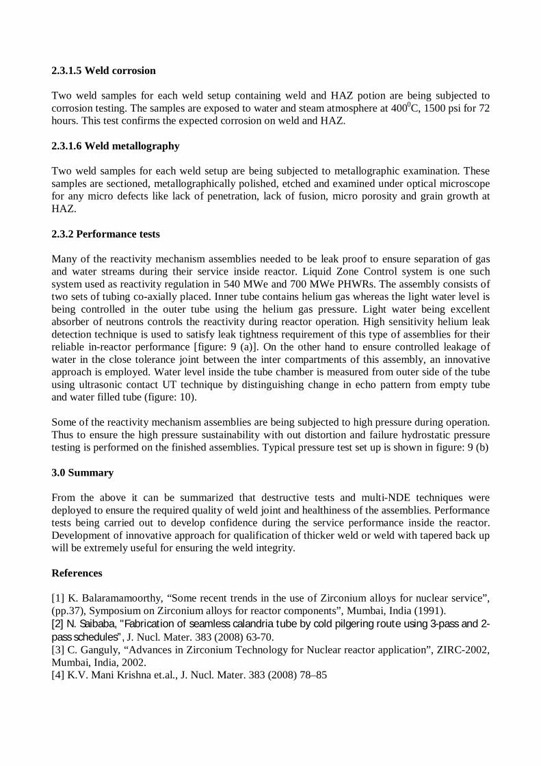
qualification of these critical assemblies are of extreme importance to ensure their desired service performance. Nuclear Fuel Complex (NFC), Hyderabad has manufactured these structural for all the operating Indian PHWRs is continuing the development of these assemblies for the upcoming 700 MWe PHWRs. The reactivity mechanism assemblies can be broadly categorized in three groups namely reactor control systems, regulating system and shut-down system. Control rod guide tube assemblies and Adjuster rod guide tube assemblies (figure:1) are part of reactivity control and regulating mechanism ,Shut-off rod guide tube assembly is a part of shut down system No. 1 (SDS#1) of 700 MWe PHWRs. The regulating devices are used for reactor power control while shut down system no.1 is used for fast termination of nuclear chain reaction in reactor core i.e. for reactor shut down. Zircaloy guide tube assemblies are located vertically inside the reactor core to facilitate the vertical movement of neutron absorbing rods in the reactor core as and when required for reactor control /shut down. The control rod and shut-off rod guide tubes are perforated to facilitate cooling of the absorber rods by moderator when inserted in to the reactor core. These assemblies have provisions for connecting to the Calandria shell at the bottom and at the top for threaded connection to corresponding stainless steel guide tube extensions. As installed, these assemblies are kept in tension by helical springs mounted at the top end of guide tube extension. The Zircaloy guide tube assemblies consist of thin walled tubes and machined components. The zircaloy tubes and machined parts are integrated by electron beam welding.
Zircaloy-4 is used as material of construction for these assemblies due to its inherent properties
conducive to the reactor environment like excellent neutron economy, high temperature corrosion resistance, superior mechanical properties etc [1]. The Zircaloy-4 tubes are manufacturing through hot extrusion followed by multi-pass cold pilgering with intermediate annealing [2-4]. The components are machined as per drawing from Zircaloy-4 blanks and rounds which are made through hot extrusion of cast ingots (Figure: 2 a , b).
Seamless tubing is integrated to machined component using electron beam welding (EBW). This has inherent advantages of better integrity and higher weld strength due to narrow heat affected zone, cleaner weld, low gaseous pick-up, higher depth of penetration etc. These welds are being qualified using a set of destructive and non-destructive techniques for evaluation of mechanical and metallurgical properties and assessment of structural integrity of weld joints. This paper describes in detail the qualification of EB weld joints of reactivity mechanism assemblies being practiced at NFC, Hyderabad. This involves non-destructive tests such as visual examination, Dye penetrant test, X-ray radiography, helium leak test and Pressure test as well as sample based destructive examination such as Pull-out test, Metallography of weld cross-section, Chemical analysis and Corrosion test. Few weld joint configurations are not feasible for volumetric examination (especially for detection of planner defect like lack of penetration, lack of fusion, cracks etc.) using X-ray radiography due to either complex joint configuration or very high component thickness limiting the X-ray beam penetration. In such cases, ensuring the required soundness of the weld joint was done using ultrasonic angle beam contact method. Table-1: Nominal chemical composition of Zircaloy-4 used for fabrication of seamless tubes and assemblies.
Elements
Sn Fe Cr Ni O H N Hf
Content (wt%) 1.5 0.21 0.1 <7X10⁻³ 0.10 <25X10-3 <65X10-3 <50X10-3
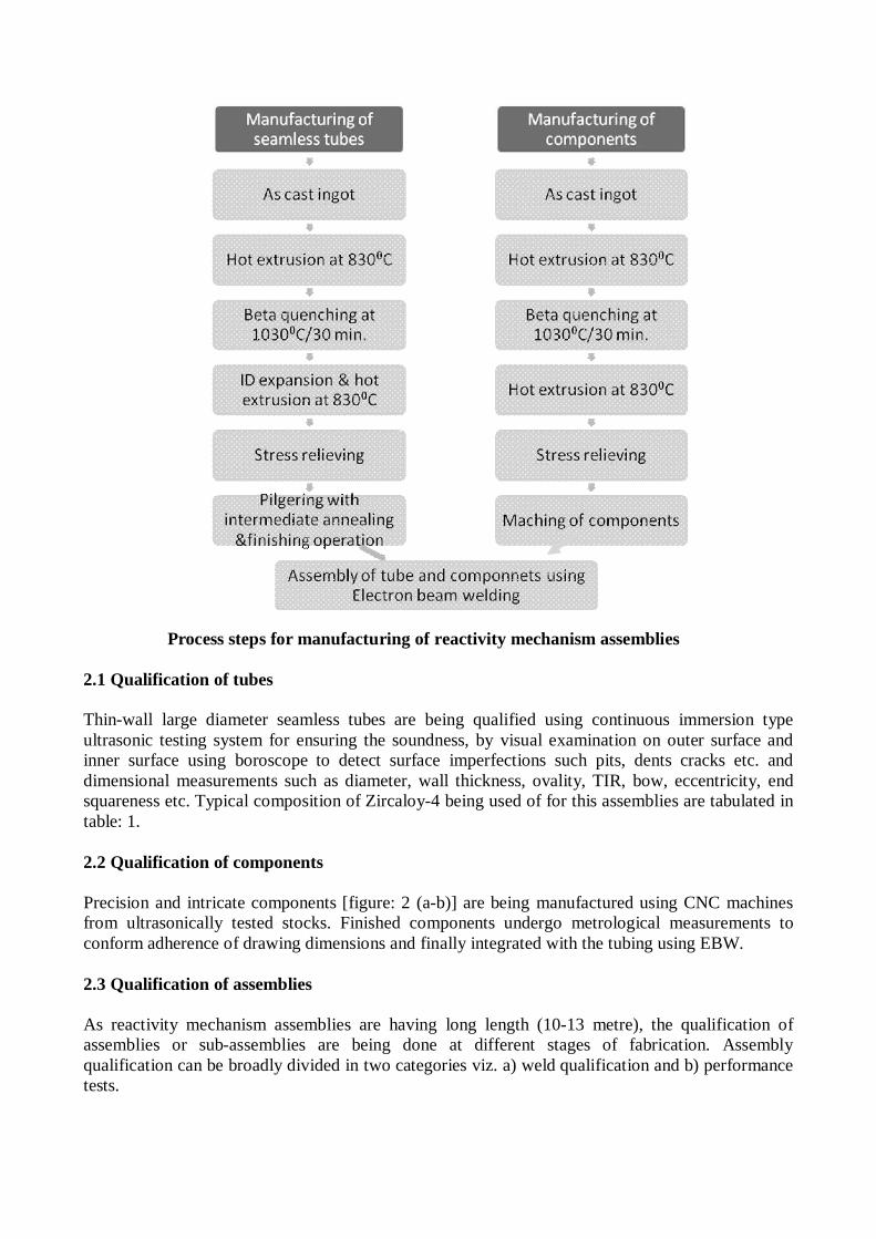
Process steps for manufacturing of reactivity mechanism assemblies 2.1 Qualification of tubes Thin-wall large diameter seamless tubes are being qualified using continuous immersion type ultrasonic testing system for ensuring the soundness, by visual examination on outer surface and inner surface using boroscope to detect surface imperfections such pits, dents cracks etc. and dimensional measurements such as diameter, wall thickness, ovality, TIR, bow, eccentricity, end squareness etc. Typical composition of Zircaloy-4 being used of for this assemblies are tabulated in table: 1. 2.2 Qualification of components Precision and intricate components [figure: 2 (a-b)] are being manufactured using CNC machines from ultrasonically tested stocks. Finished components undergo metrological measurements to conform adherence of drawing dimensions and finally integrated with the tubing using EBW. 2.3 Qualification of assemblies As reactivity mechanism assemblies are having long length (10-13 metre), the qualification of assemblies or sub-assemblies are being done at different stages of fabrication. Assembly qualification can be broadly divided in two categories viz. a) weld qualification and b) performance tests.
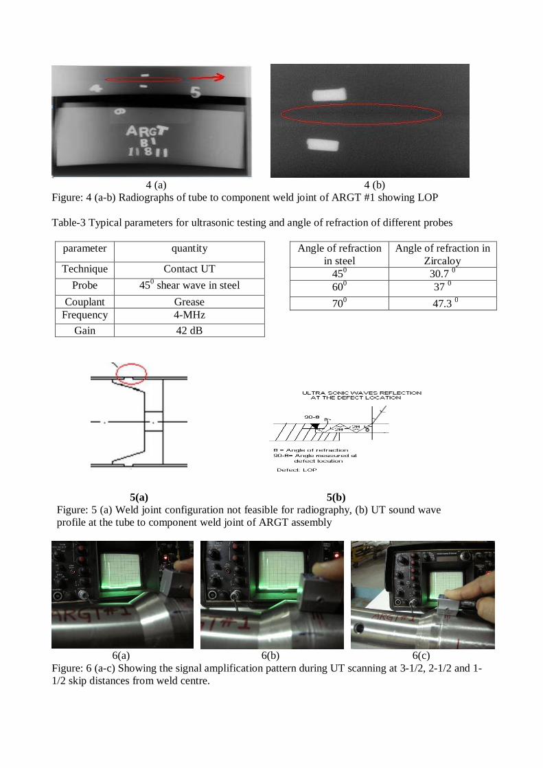
2.3.1 Weld Qualification Before commencement of welding for the actual assemblies, two set-up welds are made with the components and tubes of same sizes, from the same material and with the same joint configuration to be used for actual welds. These welds are subjected to the following tests to ensure weld integrity namely pull-out test, metallography of weld cross-section, chemical analysis, corrosion test and non destructive examination viz. visual examination, dye-penetrant test and X-ray radiography. Once the set-up welds are qualified through the above tests meeting the specified requirements, the weld parameters are recorded and the same are used during fabrication of assemblies. Typical weld joint configuration is shown in figure: 3. On the other hand actual assembly weld are being qualified using non-destructive techniques (NDT) such as visual examination, dye-penetrant and X-ray radiography. In case the weld joint is found to be unfavorable for radiography, angle beam contact UT is employed to ensure weld soundness. 2.3.1.1 X-ray radiography X-ray radiography is used as per ASME section-V for volumetric examination to ensure weld joint integrity. Single wall single image or double wall single image techniques are employed depending on the accessibility of weld. X-ray system (450 KV and 40 mA and 2 & 4 mm focal spot) along with D-4 film with or without lead intensifying screens are employed for testing. Typical EBW and radiography parameters are tabulated in table: 2(a-b). Planner defects such as lack of penetration (LOP), lack of fusion, under cut etc. and globular defects like porosity were detected in the weld joints. Figure: 4(a-b) shows the LOP in the bottom weld joint of adjuster rod guide tube assembly. 2.3.1.2 Ultrasonic test Few weld joint configurations are not feasible for radiography due to excessive weld thickness or tapered back-up beneath the weld [figure: 5(a)]. Thus ensuring desired soundness of these weld joints were a challenge. Attempts were made to qualify such welds using angle beam contact UT. Test procedure is established and standardized using a defective weld joint containing LOP confirmed by radiography (table: 3). Interaction of sound wave with the weld defect is presented in figure: 5 (b). UT and radiography were compared for the same weld joints, shown excellent agreement. Figure: 4(a-b) shows the LOP in the bottom weld joint of adjuster rod guide tube assembly. The same weld joint was subjected to UT showing the distinguishable defect signal pattern as shown in figure: 6(a-c). Finally the defective weldment was sectioned which clearly revealed an LOP of 0.15-mm width [figure: 7 (a-b)] 2.3.1.3 Pull-out test Pull-out test is being done on set-up welds to ensure the minimum weld strength. The primary acceptance criterion for qualification is based on ensuring minimum ultimate tensile strength of the base material. Failure away from weld and heat affected region is desirable for healthiness of assemblies. Figure: 8 (a-b) shows the pull-out tested sample of cobalt absorber assemblies used as control rods in 220 MWe PHWRs. 2.3.1.4 Weld chemistry Two weld samples for each weld setup are being analyzed for any pick up of atmospheric gases during (H, N & O) during welding and any depletion of alloying elements on weld and HAZ. This test will confirm the weld chemistry.
2.3.1.5 Weld corrosion Two weld samples for each weld setup containing weld and HAZ potion are being subjected to corrosion testing. The samples are exposed to water and steam atmosphere at 4000C, 1500 psi for 72 hours. This test confirms the expected corrosion on weld and HAZ. 2.3.1.6 Weld metallography Two weld samples for each weld setup are being subjected to metallographic examination. These samples are sectioned, metallographically polished, etched and examined under optical microscope for any micro defects like lack of penetration, lack of fusion, micro porosity and grain growth at HAZ. 2.3.2 Performance tests Many of the reactivity mechanism assemblies needed to be leak proof to ensure separation of gas and water streams during their service inside reactor. Liquid Zone Control system is one such system used as reactivity regulation in 540 MWe and 700 MWe PHWRs. The assembly consists of two sets of tubing co-axially placed. Inner tube contains helium gas whereas the light water level is being controlled in the outer tube using the helium gas pressure. Light water being excellent absorber of neutrons controls the reactivity during reactor operation. High sensitivity helium leak detection technique is used to satisfy leak tightness requirement of this type of assemblies for their reliable in-reactor performance [figure: 9 (a)]. On the other hand to ensure controlled leakage of water in the close tolerance joint between the inter compartments of this assembly, an innovative approach is employed. Water level inside the tube chamber is measured from outer side of the tube using ultrasonic contact UT technique by distinguishing change in echo pattern from empty tube and water filled tube (figure: 10). Some of the reactivity mechanism assemblies are being subjected to high pressure during operation. Thus to ensure the high pressure sustainability with out distortion and failure hydrostatic pressure testing is performed on the finished assemblies. Typical pressure test set up is shown in figure: 9 (b) 3.0 Summary From the above it can be summarized that destructive tests and multi-NDE techniques were deployed to ensure the required quality of weld joint and healthiness of the assemblies. Performance tests being carried out to develop confidence during the service performance inside the reactor. Development of innovative approach for qualification of thicker weld or weld with tapered back up will be extremely useful for ensuring the weld integrity. References [1] K. Balaramamoorthy, “Some recent trends in the use of Zirconium alloys for nuclear service”, (pp.37), Symposium on Zirconium alloys for reactor components”, Mumbai, India (1991). [2] N. Saibaba, "Fabrication of seamless calandria tube by cold pilgering route using 3-pass and 2-pass schedules”, J. Nucl. Mater. 383 (2008) 63-70. [3] C. Ganguly, “Advances in Zirconium Technology for Nuclear reactor application”, ZIRC-2002, Mumbai, India, 2002. [4] K.V. Mani Krishna et.al., J. Nucl. Mater. 383 (2008) 78–85
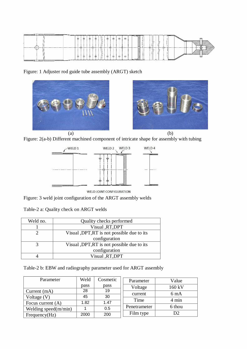
Figure: 1 Adjuster rod guide tube assembly (ARGT) sketch
(a) (b)
Figure: 2(a-b) Different machined component of intricate shape for assembly with tubing
Figure: 3 weld joint configuration of the ARGT assembly welds Table-2 a: Quality check on ARGT welds
Weld no. Quality checks performed
1 Visual ,RT,DPT 2 Visual ,DPT,RT is not possible due to its
configuration 3 Visual ,DPT,RT is not possible due to its
configuration 4 Visual ,RT,DPT
Table-2 b: EBW and radiography parameter used for ARGT assembly
Parameter Weld pass
Cosmetic pass
Current (mA) 28 19
Voltage (V) 45 30
Focus current (A) 1.82 1.47
Welding speed(m/min) 1 0.5
Frequency(Hz) 2000 200
Parameter Value Voltage 160 kV current 6 mA Time 4 min
Penetrameter 6 thou Film type D2
4 (a) 4 (b)
Figure: 4 (a-b) Radiographs of tube to component weld joint of ARGT #1 showing LOP Table-3 Typical parameters for ultrasonic testing and angle of refraction of different probes
parameter quantity
Technique Contact UT
Probe 450 shear wave in steel
Couplant Grease Frequency 4-MHz
Gain 42 dB
Angle of refraction in steel
Angle of refraction in Zircaloy
450 30.7 0 600 37 0
700 47.3 0
5(a) 5(b) Figure: 5 (a) Weld joint configuration not feasible for radiography, (b) UT sound wave profile at the tube to component weld joint of ARGT assembly
6(a) 6(b) 6(c)
Figure: 6 (a-c) Showing the signal amplification pattern during UT scanning at 3-1/2, 2-1/2 and 1-1/2 skip distances from weld centre.
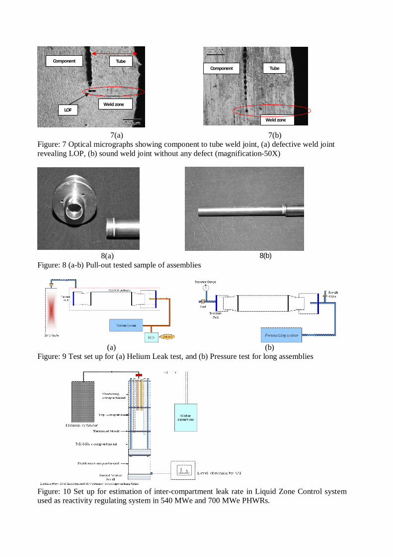
7(a) 7(b) Figure: 7 Optical micrographs showing component to tube weld joint, (a) defective weld joint revealing LOP, (b) sound weld joint without any defect (magnification-50X)
8(a) 8(b)
Figure: 8 (a-b) Pull-out tested sample of assemblies
(a) (b)
Figure: 9 Test set up for (a) Helium Leak test, and (b) Pressure test for long assemblies
Figure: 10 Set up for estimation of inter-compartment leak rate in Liquid Zone Control system used as reactivity regulating system in 540 MWe and 700 MWe PHWRs.
Weld zone LOP
Tube Component
Tube Component
Weld zone


![High Pressure Reactor 고반응기 - Komachine · 2018-11-14 · 다목적반응기. Ⅲ. 제품소개. 다목적반응기 [Multi Purpose Reactor] 고온·고압의조건에서성,](https://static.fdocuments.fr/doc/165x107/5f052a7f7e708231d41199ca/high-pressure-reactor-eee-komachine-2018-11-14-eeee.jpg)