MOTEUR / ENGINE - Menu 1 · MOTEUR / ENGINE KF4 Constructeur ... Poids minimum du vilebrequin...
28
Copyright © 2009 by CIK-FIA. All rights reserved. 1 Homologation N° 39/M/18 FICHE D’HOMOLOGATION HOMOLOGATION FORM COMMISSION INTERNATIONALE DE KARTING - FIA MOTEUR / ENGINE KF4 Constructeur Manufacturer OTK-KART-GROUP S.R.L.-(ITALY) Marque Make VORTEX Modèle Model RAD Durée de l’homologation Validity of the homologation 9 ans / 9 years Nombre de pages Number of pages 28 La présente Fiche d’Homologation reproduit descriptions, illustrations et dimensions du moteur au moment de l’homologation par la CIK-FIA. La hauteur du moteur complet sur les photos doit être de 7 cm minimum. This Homologation Form reproduces descriptions, illustrations and dimensions of the engine at the time the CIK-FIA conducted the homologation. The height of the complete engine on all photographs must be as a minimum 7 cm. PHOTO DU MOTEUR CÔTÉ PIGNON PHOTO DU MOTEUR CÔTÉ OPPOSÉ PHOTO OF DRIVE SIDE OF ENGINE PHOTO OF OPPOSITE SIDE OF ENGINE Signature et tampon de l’ASN Signature et tampon de la CIK-FIA Signature and stamp of the ASN Signature and stamp of the CIK-FIA
Transcript of MOTEUR / ENGINE - Menu 1 · MOTEUR / ENGINE KF4 Constructeur ... Poids minimum du vilebrequin...
Copyright © 2009 by CIK-FIA. All rights reserved. 1
Homologation N°
39/M/18
FICHE D’HOMOLOGATION HOMOLOGATION FORM
COMMISSION INTERNATIONALE DE KARTING - FIA
MOTEUR / ENGINE KF4
Constructeur Manufacturer OTK-KART-GROUP S.R.L.-(ITALY) Marque Make VORTEX Modèle Model RAD Durée de l’homologation Validity of the homologation 9 ans / 9 years Nombre de pages Number of pages 28 La présente Fiche d’Homologation reproduit descriptions, illustrations et dimensions du moteur au moment de l’homologation par la CIK-FIA. La hauteur du moteur complet sur les photos doit être de 7 cm minimum.
This Homologation Form reproduces descriptions, illustrations and dimensions of the engine at the time the CIK-FIA conducted the homologation. The height of the complete engine on all photographs must be as a minimum 7 cm.
PHOTO DU MOTEUR CÔTÉ PIGNON PHOTO DU MOTEUR CÔTÉ OPPOSÉ PHOTO OF DRIVE SIDE OF ENGINE PHOTO OF OPPOSITE SIDE OF ENGINE
Signature et tampon de l’ASN Signature et tampon de la CIK-FIA
Signature and stamp of the ASN Signature and stamp of the CIK-FIA
Copyright © 2009 by CIK-FIA. All rights reserved. 2
Homologation N °
39/M/18
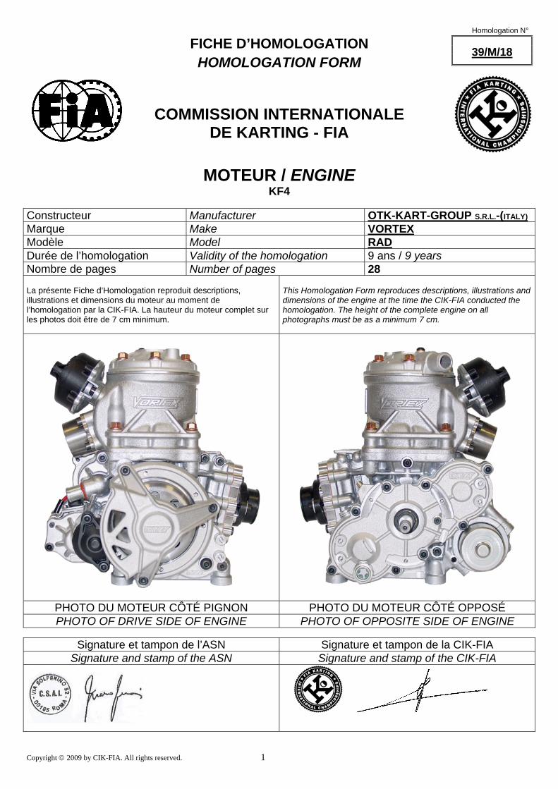
PHOTO DU MOTEUR COMPLET COTÉ PIGNON
PHOTO OF DRIVE SIDE OF THE COMPLETE
ENGINE
Copyright © 2009 by CIK-FIA. All rights reserved. 3
Homologation N °
39/M/18
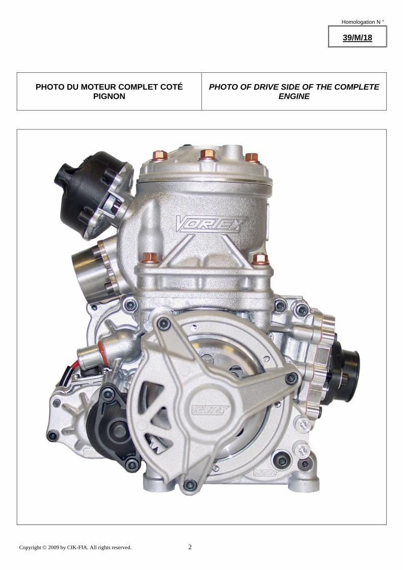
PHOTO DU MOTEUR COMPLET COTÉ OPPOSÉ AU PIGNON
PHOTO OF OPPOSITE DRIVE SIDE OF THE
COMPLETE ENGINE
Copyright © 2009 by CIK-FIA. All rights reserved. 4
Homologation N °
39/M/18
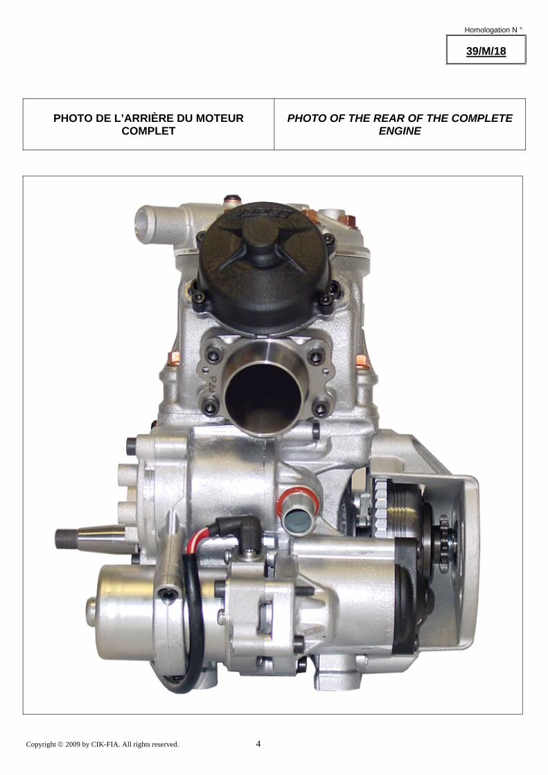
PHOTO DE L’ARRIÈRE DU MOTEUR COMPLET
PHOTO OF THE REAR OF THE COMPLETE
ENGINE
Copyright © 2009 by CIK-FIA. All rights reserved. 5
Homologation N °
39/M/18
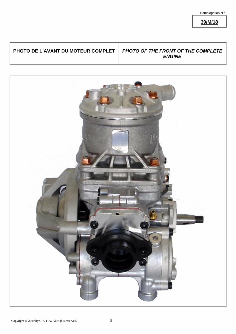
PHOTO DE L’AVANT DU MOTEUR COMPLET
PHOTO OF THE FRONT OF THE COMPLETE
ENGINE
Copyright © 2009 by CIK-FIA. All rights reserved. 6
Homologation N °
39/M/18
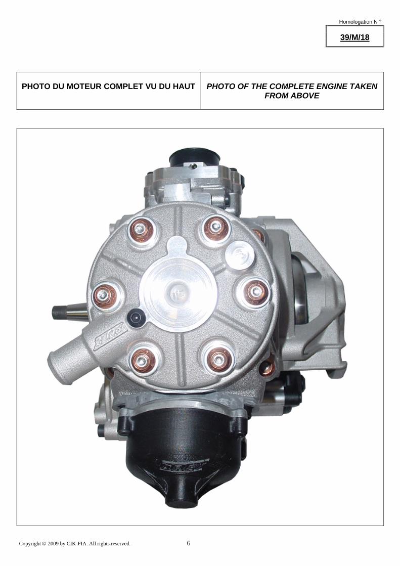
PHOTO DU MOTEUR COMPLET VU DU HAUT
PHOTO OF THE COMPLETE ENGINE TAKEN
FROM ABOVE
Copyright © 2009 by CIK-FIA. All rights reserved. 7
Homologation N °
39/M/18
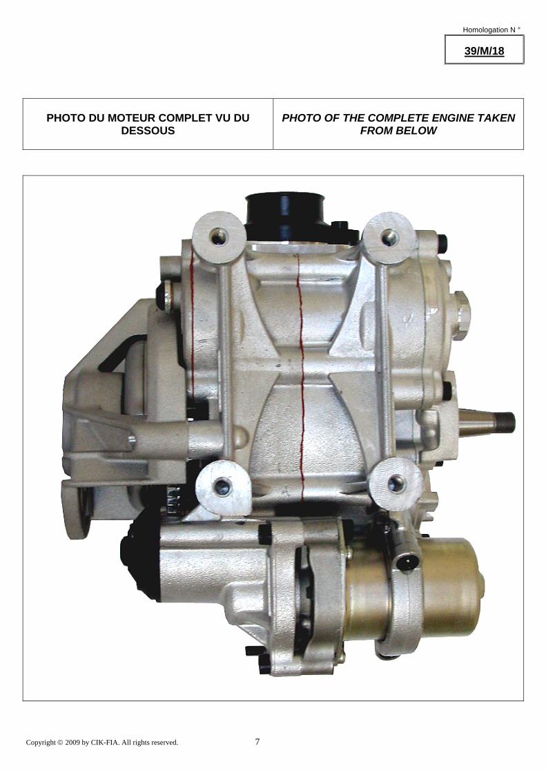
PHOTO DU MOTEUR COMPLET VU DU
DESSOUS
PHOTO OF THE COMPLETE ENGINE TAKEN
FROM BELOW
Copyright © 2009 by CIK-FIA. All rights reserved. 8
Homologation N °
39/M/18
INFORMATIONS TECHNIQUES
TECHNICAL INFORMATION
A
CARACTÉRISTIQUES
A
CHARACTERISTICS
Le nombre de décimales doit être de 2 ou en accord avec la tolérance appliquée.
The number of decimal places must be 2 or comply with the relevant tolerance. Tolérances / remarques
Tolerances & remarks
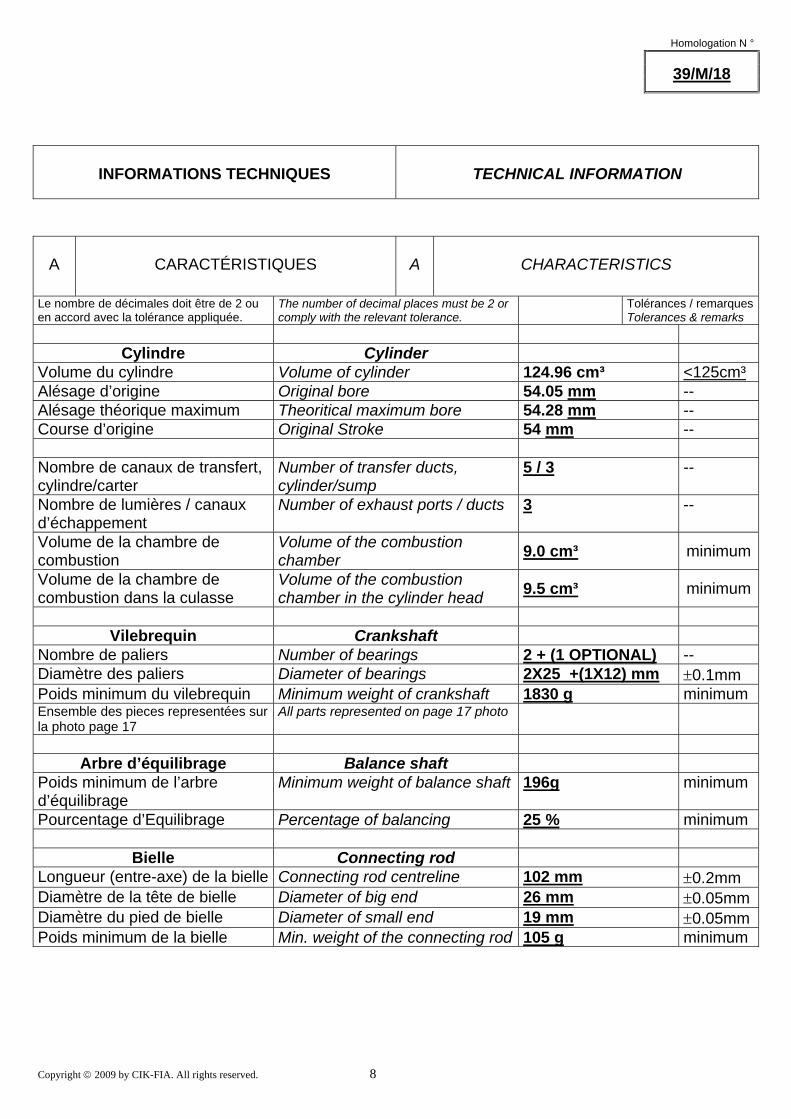
Cylindre Cylinder Volume du cylindre Volume of cylinder 124.96 cm³ <125cm³ Alésage d’origine Original bore 54.05 mm -- Alésage théorique maximum Theoritical maximum bore 54.28 mm -- Course d’origine Original Stroke 54 mm -- Nombre de canaux de transfert, cylindre/carter
Number of transfer ducts, cylinder/sump
5 / 3 --
Nombre de lumières / canaux d’échappement
Number of exhaust ports / ducts 3 --
Volume de la chambre de combustion
Volume of the combustion chamber 9.0 cm³ minimum
Volume de la chambre de combustion dans la culasse
Volume of the combustion chamber in the cylinder head 9.5 cm³ minimum
Vilebrequin Crankshaft
Nombre de paliers Number of bearings 2 + (1 OPTIONAL) -- Diamètre des paliers Diameter of bearings 2X25 +(1X12) mm ±0.1mm Poids minimum du vilebrequin Minimum weight of crankshaft 1830 g minimum Ensemble des pieces representées sur la photo page 17
All parts represented on page 17 photo
Arbre d’équilibrage Balance shaft
Poids minimum de l’arbre d’équilibrage
Minimum weight of balance shaft 196g minimum
Pourcentage d’Equilibrage Percentage of balancing 25 % minimum
Bielle Connecting rod Longueur (entre-axe) de la bielle Connecting rod centreline 102 mm ±0.2mm Diamètre de la tête de bielle Diameter of big end 26 mm ±0.05mmDiamètre du pied de bielle Diameter of small end 19 mm ±0.05mmPoids minimum de la bielle Min. weight of the connecting rod 105 g minimum
Copyright © 2009 by CIK-FIA. All rights reserved. 9
Homologation N °
39/M/18
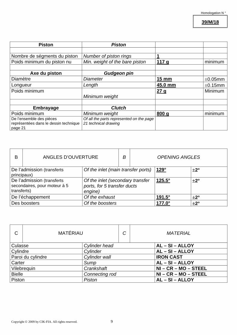
Piston Piston Nombre de ségments du piston Number of piston rings 1 Poids minimum du piston nu Min. weight of the bare piston 117 g minimum
Axe du piston Gudgeon pin Diamètre Diameter 15 mm ±0.05mmLongueur Length 45.0 mm ±0.15mmPoids minimum
Minimum weight 27 g Minimum
Embrayage Clutch
Poids minimum Minimum weight 800 g minimum De l’ensemble des pièces représentées dans le dessin technique page 21
Of all the parts represented on the page 21 technical drawing
B
ANGLES D’OUVERTURE
B
OPENING ANGLES
De l’admission (transferts principaux)
Of the inlet (main transfer ports) 129° ±2°
De l’admission (transferts secondaires, pour moteur à 5 transferts)
Of the inlet (secondary transfer ports, for 5 transfer ducts engine)
125.5° ±2°
De l’échappement Of the exhaust 191.5° ±2° Des boosters Of the boosters 177.0° ±2°
C
MATÉRIAU
C
MATERIAL
Culasse Cylinder head AL – SI – ALLOY Cylindre Cylinder AL – SI – ALLOY Paroi du cylindre Cylinder wall IRON CAST Carter Sump AL – SI – ALLOY Vilebrequin Crankshaft NI – CR – MO – STEEL Bielle Connecting rod NI – CR – MO – STEEL Piston Piston AL – SI – ALLOY
Copyright © 2009 by CIK-FIA. All rights reserved. 10
Homologation N °
39/M/18
D
PHOTOS, DESSINS & GRAPHIQUES
D
PHOTOS, DRAWINGS & GRAPHS
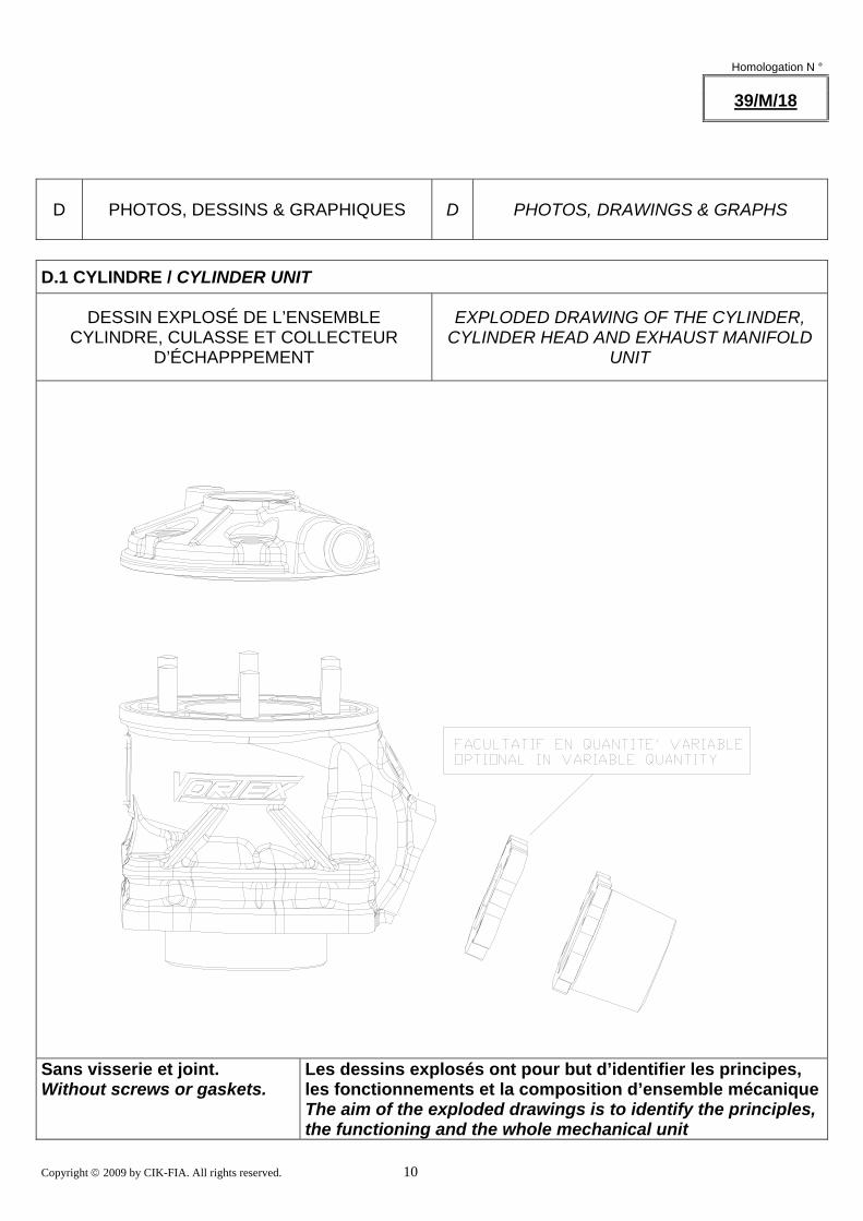
D.1 CYLINDRE / CYLINDER UNIT
DESSIN EXPLOSÉ DE L’ENSEMBLE
CYLINDRE, CULASSE ET COLLECTEUR D’ÉCHAPPPEMENT
EXPLODED DRAWING OF THE CYLINDER,
CYLINDER HEAD AND EXHAUST MANIFOLD UNIT
Sans visserie et joint. Without screws or gaskets. Les dessins explosés ont pour but d’identifier les principes,
les fonctionnements et la composition d’ensemble mécaniqueThe aim of the exploded drawings is to identify the principles, the functioning and the whole mechanical unit
Copyright © 2009 by CIK-FIA. All rights reserved. 11
Homologation N°
39/M/18
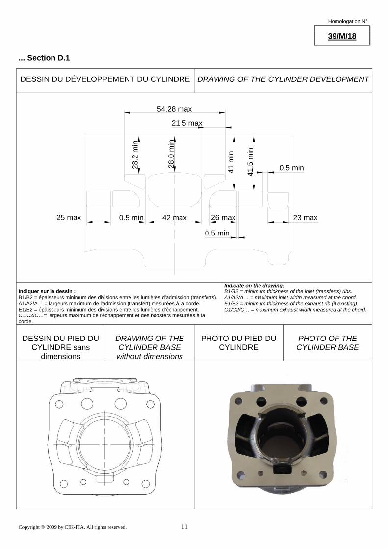
... Section D.1
DESSIN DU DÉVELOPPEMENT DU CYLINDRE
DRAWING OF THE CYLINDER DEVELOPMENT
42 max
54.28 max
21.5 max
0.5 min
41 m
in
28.0
min
28.2
min
41.5
min
26 max25 max 23 max
0.5 min
0.5 min
Indiquer sur le dessin : B1/B2 = épaisseurs minimum des divisions entre les lumières d'admission (transferts). A1/A2/A… = largeurs maximum de l'admission (transfert) mesurées à la corde. E1/E2 = épaisseurs minimum des divisions entre les lumières d'échappement. C1/C2/C…= largeurs maximum de l'échappement et des boosters mesurées à la corde.
Indicate on the drawing: B1/B2 = minimum thickness of the inlet (transferts) ribs. A1/A2/A… = maximum inlet width measured at the chord. E1/E2 = minimum thickness of the exhaust rib (if existing). C1/C2/C… = maximum exhaust width measured at the chord.
DESSIN DU PIED DU
CYLINDRE sans dimensions
DRAWING OF THE CYLINDER BASE without dimensions
PHOTO DU PIED DU
CYLINDRE
PHOTO OF THE CYLINDER BASE
Copyright © 2009 by CIK-FIA. All rights reserved. 12
Homologation N°
39/M/18
... Section D.1
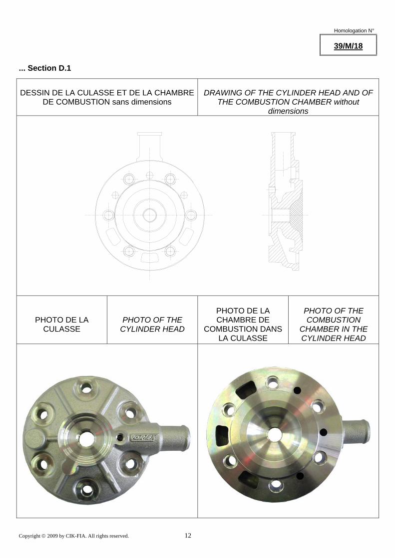
DESSIN DE LA CULASSE ET DE LA CHAMBRE
DE COMBUSTION sans dimensions
DRAWING OF THE CYLINDER HEAD AND OF
THE COMBUSTION CHAMBER without dimensions
PHOTO DE LA
CULASSE
PHOTO OF THE
CYLINDER HEAD
PHOTO DE LA CHAMBRE DE
COMBUSTION DANS LA CULASSE
PHOTO OF THE COMBUSTION
CHAMBER IN THE CYLINDER HEAD
Copyright © 2009 by CIK-FIA. All rights reserved. 13
Homologation N°
39/M/18
... Section D.1
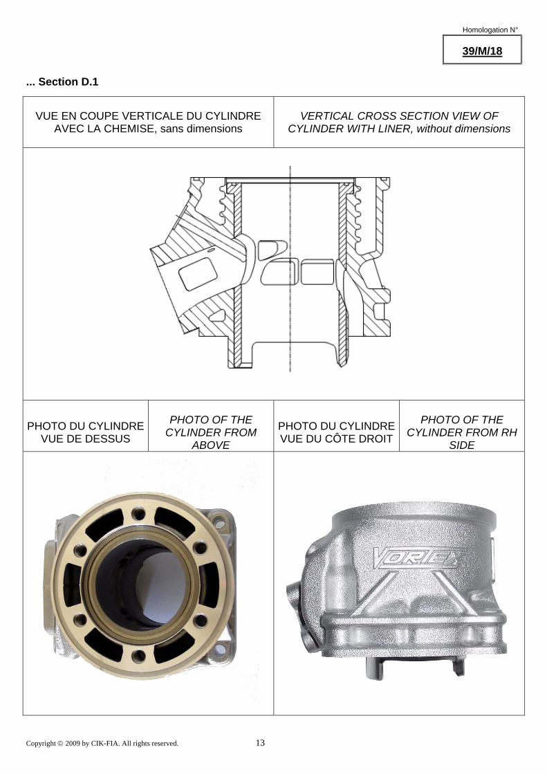
VUE EN COUPE VERTICALE DU CYLINDRE
AVEC LA CHEMISE, sans dimensions
VERTICAL CROSS SECTION VIEW OF
CYLINDER WITH LINER, without dimensions
PHOTO DU CYLINDRE
VUE DE DESSUS
PHOTO OF THE
CYLINDER FROM ABOVE
PHOTO DU CYLINDRE VUE DU CÔTE DROIT
PHOTO OF THE
CYLINDER FROM RH SIDE
Copyright © 2009 by CIK-FIA. All rights reserved. 14
Homologation N°
39/M/18
... Section D.1
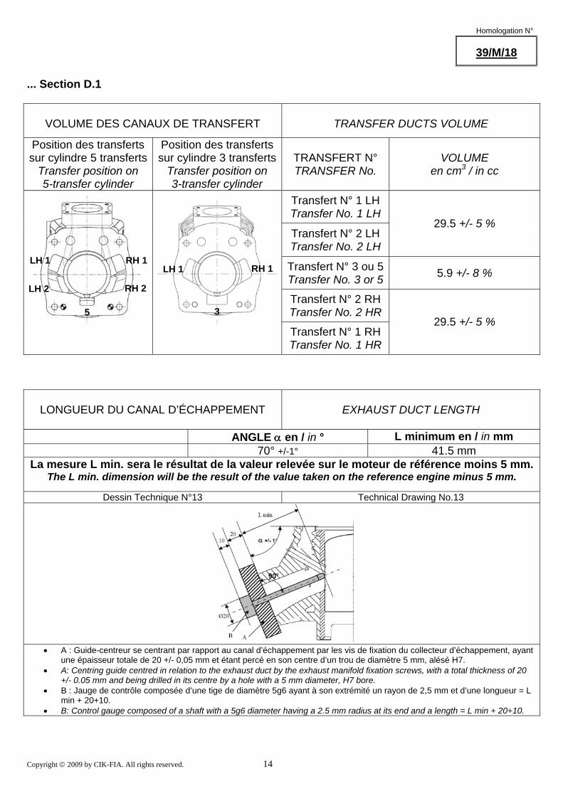
VOLUME DES CANAUX DE TRANSFERT
TRANSFER DUCTS VOLUME
Position des transferts sur cylindre 5 transferts
Transfer position on 5-transfer cylinder
Position des transferts sur cylindre 3 transferts
Transfer position on 3-transfer cylinder
TRANSFERT N° TRANSFER No.
VOLUME en cm3 / in cc
Transfert N° 1 LH Transfer No. 1 LH
Transfert N° 2 LH Transfer No. 2 LH
29.5 +/- 5 %
Transfert N° 3 ou 5Transfer No. 3 or 5 5.9 +/- 8 %
Transfert N° 2 RH Transfer No. 2 HR
Transfert N° 1 RH Transfer No. 1 HR
29.5 +/- 5 %
LONGUEUR DU CANAL D’ÉCHAPPEMENT
EXHAUST DUCT LENGTH
ANGLE α en / in ° L minimum en / in mm 70° +/-1° 41.5 mm
La mesure L min. sera le résultat de la valeur relevée sur le moteur de référence moins 5 mm. The L min. dimension will be the result of the value taken on the reference engine minus 5 mm.
Dessin Technique N°13 Technical Drawing No.13
• A : Guide-centreur se centrant par rapport au canal d’échappement par les vis de fixation du collecteur d’échappement, ayant
une épaisseur totale de 20 +/- 0,05 mm et étant percé en son centre d’un trou de diamètre 5 mm, alésé H7. • A: Centring guide centred in relation to the exhaust duct by the exhaust manifold fixation screws, with a total thickness of 20
+/- 0.05 mm and being drilled in its centre by a hole with a 5 mm diameter, H7 bore. • B : Jauge de contrôle composée d’une tige de diamètre 5g6 ayant à son extrémité un rayon de 2,5 mm et d’une longueur = L
min + 20+10. • B: Control gauge composed of a shaft with a 5g6 diameter having a 2.5 mm radius at its end and a length = L min + 20+10.
LH 1
LH 2
RH 1 LH 1
RH 2
RH 1
5 3
Copyright © 2009 by CIK-FIA. All rights reserved. 15
Homologation N°
39/M/18
... Section D.1
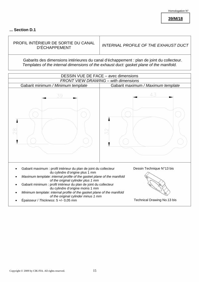
PROFIL INTÉRIEUR DE SORTIE DU CANAL
D’ÉCHAPPEMENT
INTERNAL PROFILE OF THE EXHAUST DUCT
Gabarits des dimensions intérieures du canal d’échappement : plan de joint du collecteur. Templates of the internal dimensions of the exhaust duct: gasket plane of the manifold.
DESSIN VUE DE FACE – avec dimensions FRONT VIEW DRAWING – with dimensions
Gabarit minimum / Minimum template Gabarit maximum / Maximum template
• Gabarit maximum : profil intérieur du plan de joint du collecteur du cylindre d’origine plus 1 mm • Maximum template: internal profile of the gasket plane of the manifold of the original cylinder plus 1 mm • Gabarit minimum : profil intérieur du plan de joint du collecteur du cylindre d’origine moins 1 mm • Minimum template: internal profile of the gasket plane of the manifold of the original cylinder minus 1 mm • Épaisseur / Thickness: 5 +/- 0,05 mm
Dessin Technique N°13 bis
Technical Drawing No.13 bis
Copyright © 2009 by CIK-FIA. All rights reserved. 16
Homologation N°
39/M/18
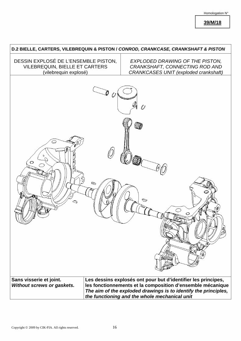
D.2 BIELLE, CARTERS, VILEBREQUIN & PISTON / CONROD, CRANKCASE, CRANKSHAFT & PISTON
DESSIN EXPLOSÉ DE L’ENSEMBLE PISTON,
VILEBREQUIN, BIELLE ET CARTERS (vilebrequin explosé)
EXPLODED DRAWING OF THE PISTON, CRANKSHAFT, CONNECTING ROD AND CRANKCASES UNIT (exploded crankshaft)
Sans visserie et joint. Without screws or gaskets. Les dessins explosés ont pour but d’identifier les principes,
les fonctionnements et la composition d’ensemble mécaniqueThe aim of the exploded drawings is to identify the principles, the functioning and the whole mechanical unit

Copyright © 2009 by CIK-FIA. All rights reserved. 17
Homologation N °
39/M/18
...Section D.2
PHOTO DE L’EMBIELLAGE
PHOTO OF THE CRANKSHAFT & CONROD
PHOTO DE LA BIELLE
PHOTO OF THE CONROD
DESSIN DU PISTON (DIMENSIONS
PRINCIPALES avec tolérances)
DRAWING OF THE PISTON (MAIN
DIMENSIONS incl. tolerances)

Copyright © 2009 by CIK-FIA. All rights reserved. 18
Homologation N°
39/M/18
...Section D.2
PHOTO INTÉRIEURE DU CARTER DROIT
PHOTO OF THE
INSIDE OF THE RH CRANKCASE
PHOTO INTÉRIEURE DU CARTER GAUCHE
PHOTO OF THE
INSIDE OF THE LH CRANKCASE
DESSIN DE L’ENSEMBLE VILEBREQUIN - BIELLE (DIMENSIONS avec tolérances, largeurs
pied & tête de bielle, largeur & diamètre des contrepoids)
DRAWING OF THE CRANKSHAFT - CON ROD UNIT (DIMENSIONS incl. tolerances, big & small
ends thickness, crank mass thickness & diameter )
Copyright © 2009 by CIK-FIA. All rights reserved. 19
Homologation N°
39/M/18
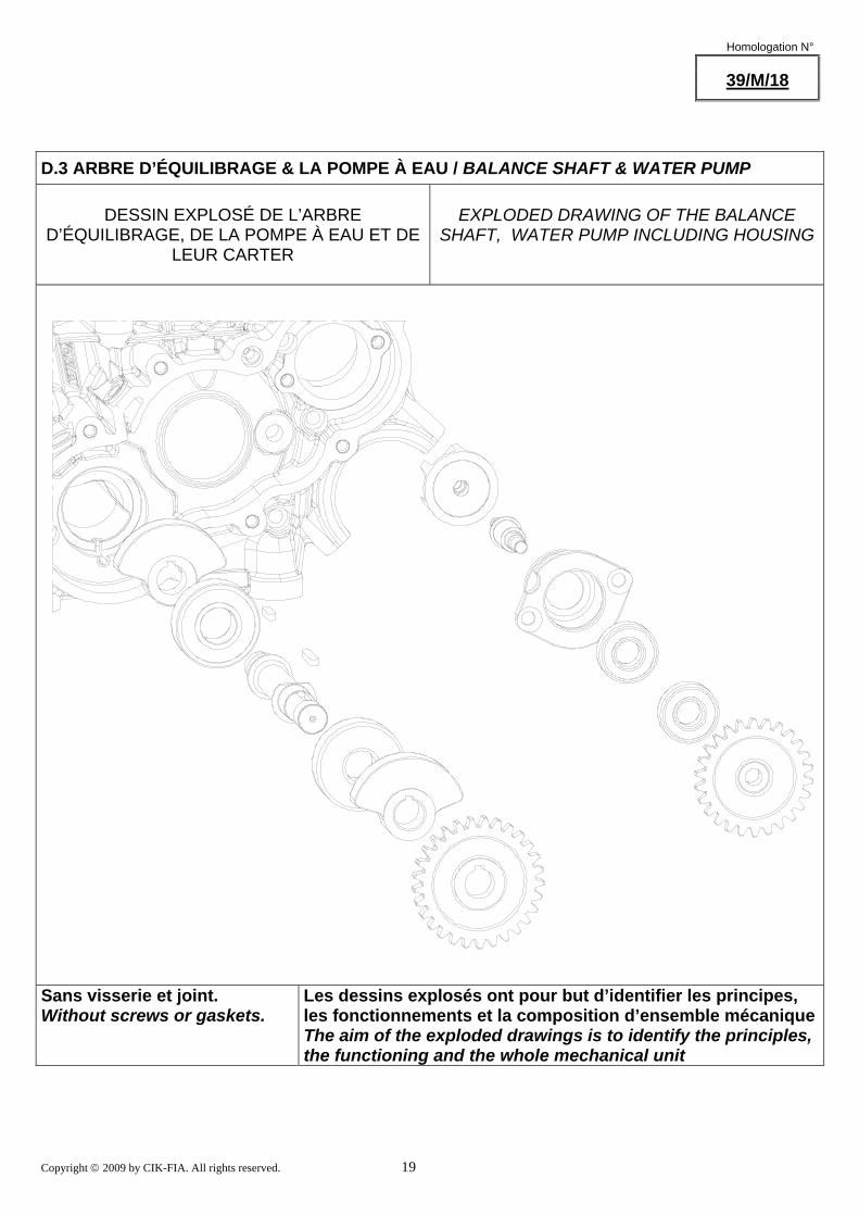
D.3 ARBRE D’ÉQUILIBRAGE & LA POMPE À EAU / BALANCE SHAFT & WATER PUMP
DESSIN EXPLOSÉ DE L’ARBRE D’ÉQUILIBRAGE, DE LA POMPE À EAU ET DE
LEUR CARTER
EXPLODED DRAWING OF THE BALANCE
SHAFT, WATER PUMP INCLUDING HOUSING
Sans visserie et joint. Without screws or gaskets. Les dessins explosés ont pour but d’identifier les principes,
les fonctionnements et la composition d’ensemble mécaniqueThe aim of the exploded drawings is to identify the principles, the functioning and the whole mechanical unit
Copyright © 2009 by CIK-FIA. All rights reserved. 20
Homologation N °
39/M/18
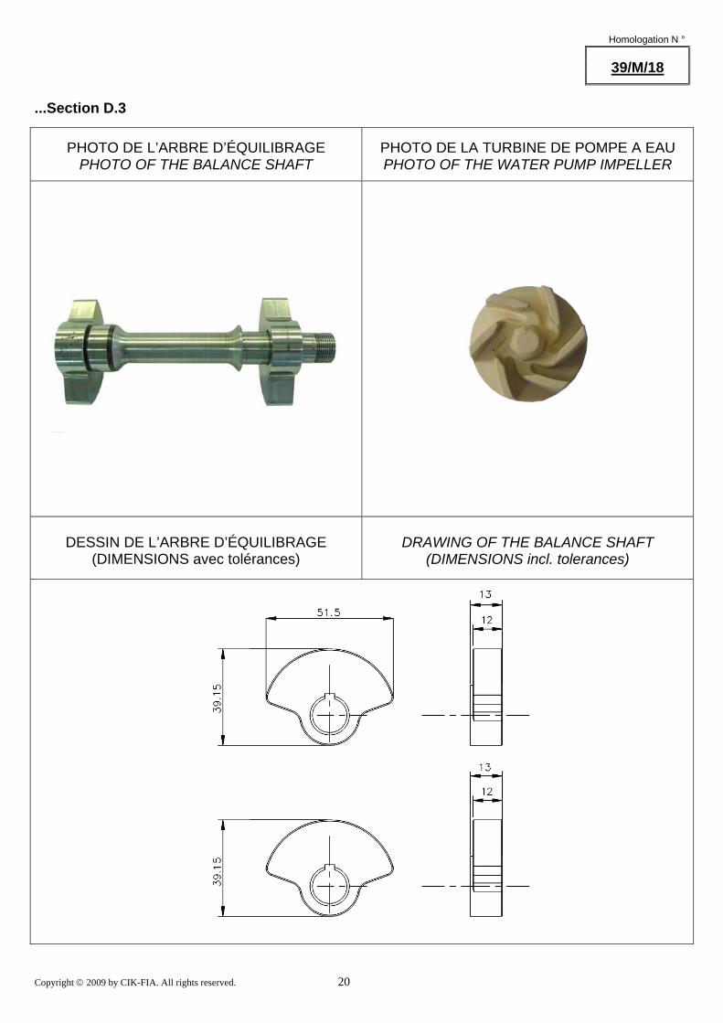
...Section D.3
PHOTO DE L’ARBRE D’ÉQUILIBRAGE
PHOTO OF THE BALANCE SHAFT
PHOTO DE LA TURBINE DE POMPE A EAU PHOTO OF THE WATER PUMP IMPELLER
DESSIN DE L’ARBRE D’ÉQUILIBRAGE
(DIMENSIONS avec tolérances)
DRAWING OF THE BALANCE SHAFT
(DIMENSIONS incl. tolerances)
Copyright © 2009 by CIK-FIA. All rights reserved. 21
Homologation N°
39/M/18
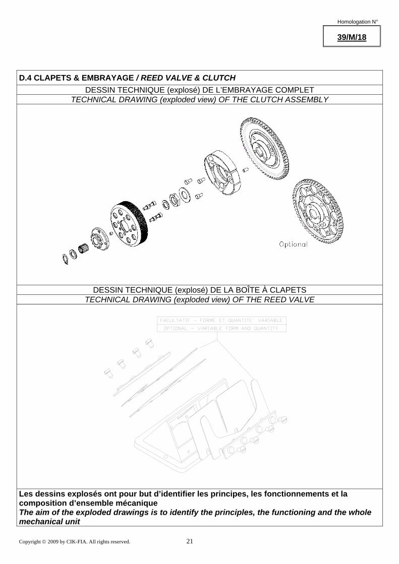
D.4 CLAPETS & EMBRAYAGE / REED VALVE & CLUTCH DESSIN TECHNIQUE (explosé) DE L’EMBRAYAGE COMPLET
TECHNICAL DRAWING (exploded view) OF THE CLUTCH ASSEMBLY
DESSIN TECHNIQUE (explosé) DE LA BOÎTE À CLAPETS TECHNICAL DRAWING (exploded view) OF THE REED VALVE
Les dessins explosés ont pour but d’identifier les principes, les fonctionnements et la composition d’ensemble mécanique The aim of the exploded drawings is to identify the principles, the functioning and the whole mechanical unit
Copyright © 2009 by CIK-FIA. All rights reserved. 22
Homologation N°
39/M/18
... Section D.4
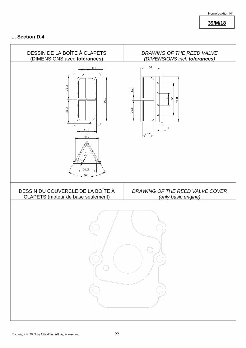
DESSIN DE LA BOÎTE À CLAPETS
(DIMENSIONS avec tolérances)
DRAWING OF THE REED VALVE (DIMENSIONS incl. tolerances)
DESSIN DU COUVERCLE DE LA BOÎTE À
CLAPETS (moteur de base seulement)
DRAWING OF THE REED VALVE COVER
(only basic engine)
Copyright © 2009 by CIK-FIA. All rights reserved. 23
Homologation N°
39/M/18
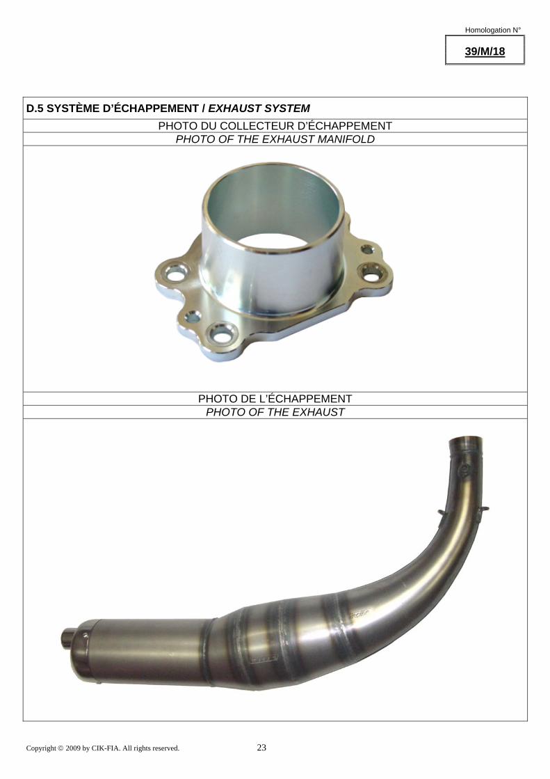
D.5 SYSTÈME D’ÉCHAPPEMENT / EXHAUST SYSTEM PHOTO DU COLLECTEUR D’ÉCHAPPEMENT
PHOTO OF THE EXHAUST MANIFOLD
PHOTO DE L’ÉCHAPPEMENT PHOTO OF THE EXHAUST
Copyright © 2009 by CIK-FIA. All rights reserved. 24
Homologation N°
39/M/18
... Section D.5
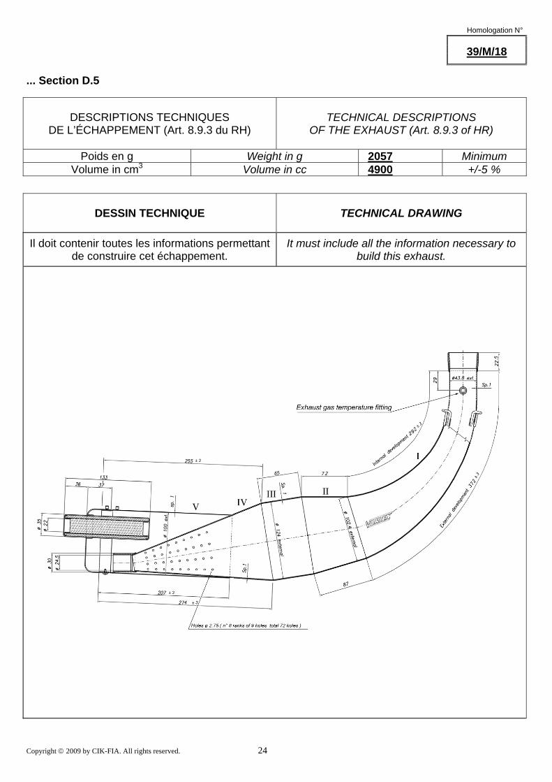
DESCRIPTIONS TECHNIQUES
DE L’ÉCHAPPEMENT (Art. 8.9.3 du RH)
TECHNICAL DESCRIPTIONS
OF THE EXHAUST (Art. 8.9.3 of HR)
Poids en g Weight in g 2057 Minimum Volume in cm3 Volume in cc 4900 +/-5 %
DESSIN TECHNIQUE
TECHNICAL DRAWING
Il doit contenir toutes les informations permettant de construire cet échappement.
It must include all the information necessary to build this exhaust.
Copyright © 2009 by CIK-FIA. All rights reserved. 25
Homologation N°
39/M/18
... Section D.5
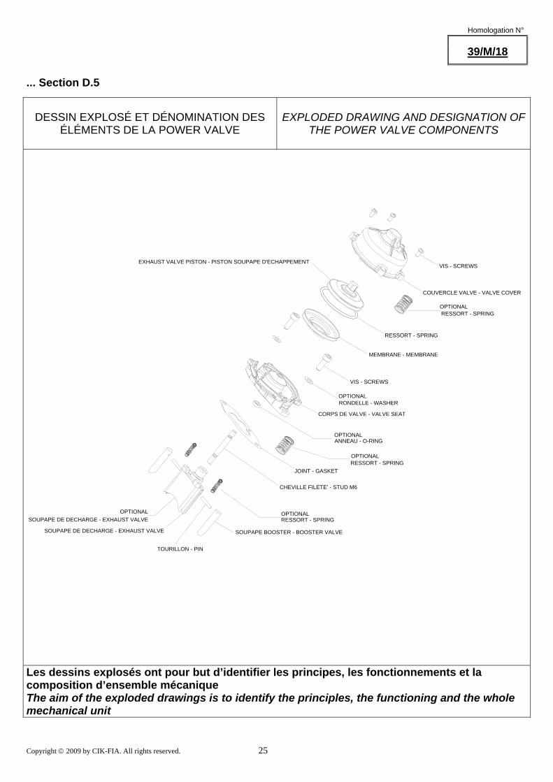
DESSIN EXPLOSÉ ET DÉNOMINATION DES
ÉLÉMENTS DE LA POWER VALVE
EXPLODED DRAWING AND DESIGNATION OF
THE POWER VALVE COMPONENTS
VIS - SCREWS
COUVERCLE VALVE - VALVE COVER
EXHAUST VALVE PISTON - PISTON SOUPAPE D'ECHAPPEMENT
RESSORT - SPRING
MEMBRANE - MEMBRANE
VIS - SCREWS
RONDELLE - WASHER
CORPS DE VALVE - VALVE SEAT
ANNEAU - O-RING
JOINT - GASKETRESSORT - SPRING
CHEVILLE FILETE' - STUD M6
TOURILLON - PIN
SOUPAPE DE DECHARGE - EXHAUST VALVE
SOUPAPE DE DECHARGE - EXHAUST VALVE
SOUPAPE BOOSTER - BOOSTER VALVE
RESSORT - SPRING
RESSORT - SPRINGOPTIONAL
OPTIONAL
OPTIONAL
OPTIONAL
OPTIONALOPTIONAL
Les dessins explosés ont pour but d’identifier les principes, les fonctionnements et la composition d’ensemble mécanique The aim of the exploded drawings is to identify the principles, the functioning and the whole mechanical unit

Copyright © 2009 by CIK-FIA. All rights reserved. 26
Homologation N°
39/M/18
D.6 DÉMARREUR / STARTER
DESSIN EXPLOSÉ DU GROUPE DÉMARREUR ET DE SON CARTER
EXPLODED DRAWING OF THE STARTING
UNIT AND OF ITS HOUSING
Sans visserie et joint. Without screws or gaskets. Les dessins explosés ont pour but d’identifier les principes,
les fonctionnements et la composition d’ensemble mécaniqueThe aim of the exploded drawings is to identify the principles, the functioning and the whole mechanical unit
Copyright © 2009 by CIK-FIA. All rights reserved. 27
Homologation N °
39/M/18
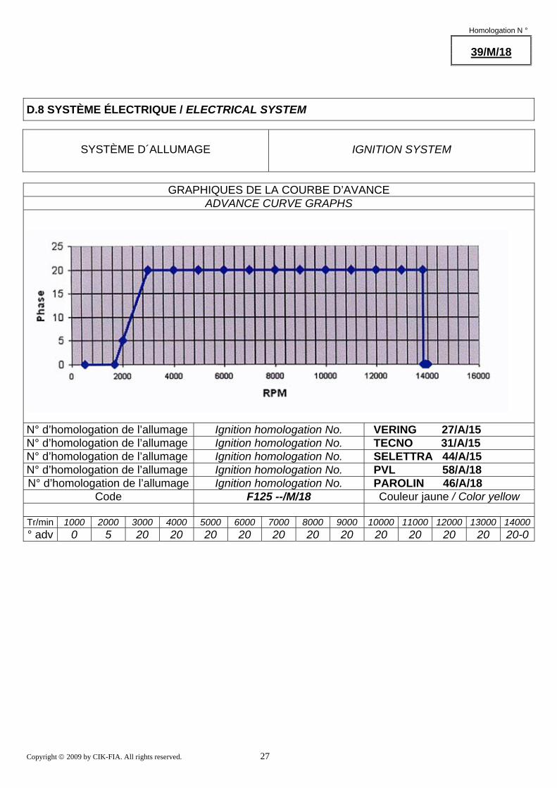
D.8 SYSTÈME ÉLECTRIQUE / ELECTRICAL SYSTEM
SYSTÈME D´ALLUMAGE
IGNITION SYSTEM
GRAPHIQUES DE LA COURBE D’AVANCE
ADVANCE CURVE GRAPHS
N° d’homologation de l’allumage Ignition homologation No. VERING 27/A/15 N° d’homologation de l’allumage Ignition homologation No. TECNO 31/A/15 N° d’homologation de l’allumage Ignition homologation No. SELETTRA 44/A/15 N° d’homologation de l’allumage Ignition homologation No. PVL 58/A/18 N° d’homologation de l’allumage Ignition homologation No. PAROLIN 46/A/18
Code F125 --/M/18 Couleur jaune / Color yellow
Tr/min 1000 2000 3000 4000 5000 6000 7000 8000 9000 10000 11000 12000 13000 14000° adv 0 5 20 20 20 20 20 20 20 20 20 20 20 20-0
Copyright © 2009 by CIK-FIA. All rights reserved. 28
Homologation N°
39/M/18
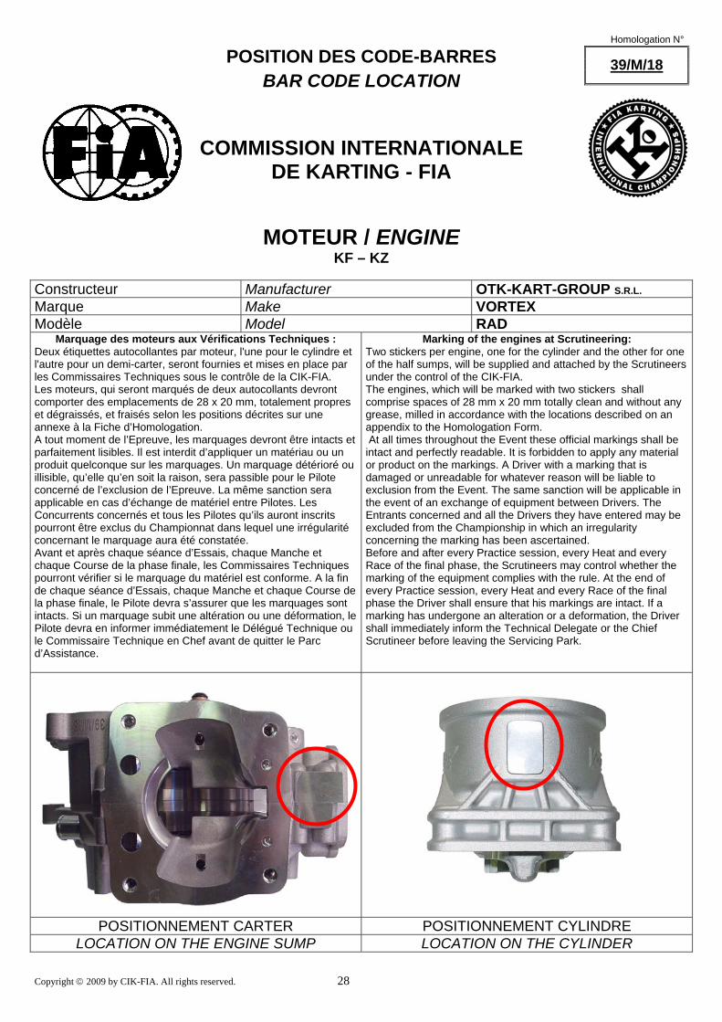
POSITION DES CODE-BARRES BAR CODE LOCATION
COMMISSION INTERNATIONALE DE KARTING - FIA
MOTEUR / ENGINE KF – KZ
Constructeur Manufacturer OTK-KART-GROUP S.R.L. Marque Make VORTEX Modèle Model RAD
Marquage des moteurs aux Vérifications Techniques : Deux étiquettes autocollantes par moteur, l'une pour le cylindre et l'autre pour un demi-carter, seront fournies et mises en place par les Commissaires Techniques sous le contrôle de la CIK-FIA. Les moteurs, qui seront marqués de deux autocollants devront comporter des emplacements de 28 x 20 mm, totalement propres et dégraissés, et fraisés selon les positions décrites sur une annexe à la Fiche d’Homologation. A tout moment de l’Epreuve, les marquages devront être intacts et parfaitement lisibles. Il est interdit d’appliquer un matériau ou un produit quelconque sur les marquages. Un marquage détérioré ou illisible, qu’elle qu’en soit la raison, sera passible pour le Pilote concerné de l’exclusion de l’Epreuve. La même sanction sera applicable en cas d’échange de matériel entre Pilotes. Les Concurrents concernés et tous les Pilotes qu’ils auront inscrits pourront être exclus du Championnat dans lequel une irrégularité concernant le marquage aura été constatée. Avant et après chaque séance d’Essais, chaque Manche et chaque Course de la phase finale, les Commissaires Techniques pourront vérifier si le marquage du matériel est conforme. A la fin de chaque séance d’Essais, chaque Manche et chaque Course de la phase finale, le Pilote devra s’assurer que les marquages sont intacts. Si un marquage subit une altération ou une déformation, le Pilote devra en informer immédiatement le Délégué Technique ou le Commissaire Technique en Chef avant de quitter le Parc d’Assistance.
Marking of the engines at Scrutineering: Two stickers per engine, one for the cylinder and the other for one of the half sumps, will be supplied and attached by the Scrutineers under the control of the CIK-FIA. The engines, which will be marked with two stickers shall comprise spaces of 28 mm x 20 mm totally clean and without any grease, milled in accordance with the locations described on an appendix to the Homologation Form. At all times throughout the Event these official markings shall be intact and perfectly readable. It is forbidden to apply any material or product on the markings. A Driver with a marking that is damaged or unreadable for whatever reason will be liable to exclusion from the Event. The same sanction will be applicable in the event of an exchange of equipment between Drivers. The Entrants concerned and all the Drivers they have entered may be excluded from the Championship in which an irregularity concerning the marking has been ascertained. Before and after every Practice session, every Heat and every Race of the final phase, the Scrutineers may control whether the marking of the equipment complies with the rule. At the end of every Practice session, every Heat and every Race of the final phase the Driver shall ensure that his markings are intact. If a marking has undergone an alteration or a deformation, the Driver shall immediately inform the Technical Delegate or the Chief Scrutineer before leaving the Servicing Park.
POSITIONNEMENT CARTER POSITIONNEMENT CYLINDRE LOCATION ON THE ENGINE SUMP LOCATION ON THE CYLINDER


![Étude de cas de projet : Renewable Engine [Moteur renouvelable]seupb.eu/.../RenewableEngine_CaseStudy1_FR_edit.pdfpour servir de banc d’essai à l’élaboration de technologies](https://static.fdocuments.fr/doc/165x107/601d64d972e52429307fd479/tude-de-cas-de-projet-renewable-engine-moteur-renouvelableseupbeurenewableenginecasestudy1freditpdf.jpg)