MicroMATV - Diseño y fabricación de componentes ... · MicroMATV EVO 300 + IFA 3000 book ......
14
MicroMATV EVO D ● Amplificador Selectivo Programable Amplificador Selectivo Programable con AGC ● Amplificateur Sélectif Programmable Amplificateur Sélectif Programmable avec AGC ● Selective Programmable Amplifier Selective Programmable Amplifier with AGC ● Amplificatore selettivo programmabile Amplificatore selettivo programmabile con AGC
Transcript of MicroMATV - Diseño y fabricación de componentes ... · MicroMATV EVO 300 + IFA 3000 book ......
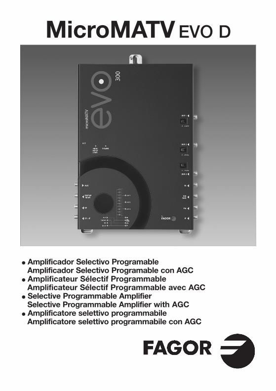
MicroMATV EVO D
� Amplificador Selectivo ProgramableAmplificador Selectivo Programable con AGC
� Amplificateur Sélectif ProgrammableAmplificateur Sélectif Programmable avec AGC
� Selective Programmable AmplifierSelective Programmable Amplifier with AGC
� Amplificatore selettivo programmabileAmplificatore selettivo programmabile con AGC

2
COMMANDES1. Entrées UHF2. Sortie 24 VDC 100 mA3. Entrée BI4. Entrée BIII / DAB5. Entrée FM6. Entrée BIS7. Sortie BIS+RF8. Sortie RF9. Sortie TEST-RF
10. Entrée Auxiliaire-TV11. DEL configuration
entrées12. Connecteur de l’unité
de contrôle13. Signalisation14. Entrée secteur15. Prise de terre
CONTROLES1. Entradas UHF2. Salida 24 VDC total:
100 mA3. Entrada BI 4. Entrada BIII / DAB5. Entrada FM6. Entrada 1ª FI SAT7. Salida1ª FI SAT+RF8. Salida RF9. Salida TEST-RF
10. Entrada Auxiliar-TV11. Led Nivel de entada Alto12. Conector para Unidad
de Control13. Led Alimentación14. Entrada de Red15. Toma de tierra
14
15
9
12
10
11
13
87
3
1
2
4
56
250 40
CONTROLLI1. Ingressi UHF2. Uscita a 24 VDC 100 mA3. Ingresso BI4. Ingresso BIII / DAB5. Ingresso FM 6. Ingresso FI SAT7. Uscita FI SAT+RF8. Uscita RF9. Uscita TEST-RF
10. Ingresso ausiliare TV11. Led configuratione
de ingressi12. Connettore di
programmazione13. Led di controllo14. Ingresso di rete15. Presa a terra
CONTROLS1. UHF inputs2. 24 VDC 100 mA
output3. BI input4. BIII / DAB input5. FM input 6. 1st IF SAT input 7. 1st IF SAT+RF output8. RF output 9. TEST-RF output
10. Auxiliary TV input11. Led input configuration12. Programming
connector13. Power LED14. Mains input15. Grounding
COMANDOS1. Entradas UHF2. Saída 24 VDC 100 mA3. Entrada BI4. Entrada BIII / DAB5. Entrada FM 6. Entrada FI SAT7. Saída FI SAT+RF8. Saída RF9. Saída TEST-RF
10. Entrada Auxiliar TV11. Led do configuração
entradas12. Conector de
programação13. LED do Controlo14. Entrada de Rede15. Fio de terra
REGLER1. Eingänge UHF2. Ausgang 24 VDC
100 mA3. Eingang BI 4. Eingang BIII / DAB5. Eingang FM6. Eingang SAT 7. Ausgang SAT+RF8. Ausgang RF9. Ausgang TEST-RF
10. Hilfseingang -TV11. Led Konfiguration
Eingänge12. Programmierstecker13. LED14. Netzanschluß15. Erdung
� Características principalesDie hanpteigeuschaften
Característiques principalesMain specifications
Caratteristiche principaliCaracterístiques principais
Banda cubierta Band Bande couverte Bands Covered Banda coperta Banda coberta
Frecuencia Frequenz Fréquence Frequency Frequenza Frequência
Ganancia Vertärkung Gain Gain Guadagno Ganho
Regulación de entrada Abstimmung Eingang Réglage d’entrée Input adjustment Regolazione d’ingresso Regulação de entrada
Regulación de salida Abstimmung Ausgang Réglage de sortie Output adjustment Regolazione d’uscita Regulação de saída
Selectividad ±20MHz Scharfeinstellung ±20MHz Sélectivité ±20MHz Selectivity ±20MHz Selettività ±20MHz Selectividade ±20MHz
Figura de ruido Rauschfaktor Facteur de bruit Noise factor Fattore di rumorosità Factor ruído
Nivel de entrada Operativer Eingangspegel Niveau d’entrée Operating input level Livello d’ingresso Nível opertivo de entrada
Alimentación para Strom für Alimentation pour Power for Alimentazione per Alimentaçãoprevios Vorverstärker pre-amplificateur pre-amplifier pre-amplificatore previo de antena
Nivel de salida Ausgangspegel Niveau de sortie Output level Livello di uscita Nivel de saída
Salida de Test Test Ausgang Sortie Test Test output Uscite di Test Saída de Test
CAG AGC CAG AGC CAG CAG
Rango de CAG AGC Plage de CAG AGC range Rango di CAG Margem CAG
Tensión alimentación Spannungsversorgung Alimentation Power supply voltage Tensione di alimentazione Tensão alimentação
Temperatura de Funktionstemperatur Température de Operating Temperatura di Temperatura de funcionamiento fonctionnement temperature funzionamento funcionamento
E D F UK I P M
360
* *
* Only MicroMATV Evo 200 & 300 models.
* –3 dB model 300 & 300 C
** Available models 12 V, 60 mA
3
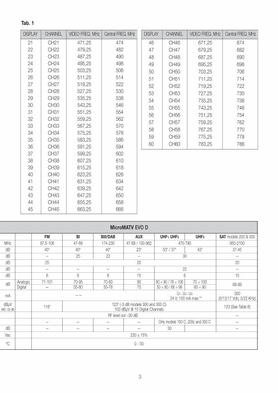
FM BI BIII/DAB AUX UHF1, UHF2 UHF3 SAT models 200 & 300
MHz 87,5-108 47-68 174-230 47-68 / 130-862 470-790 950-2150
dB 40* 40* 40* 23* 53* / 37* 43* 37-45
dB — 25 23 — 30 —
dB 25 20 20
dB — — — — 22 —
dB 6 6 8 15 6 15
dBAnalogic 71-101 70-95 70-93 90 60 ÷ 90 / 76 ÷ 106 70 ÷ 100
68-88Digital — 55-80 55-78 75 50 ÷ 80 / 66 ÷ 96 60 ÷ 90
mA —— U1 + U2 + U3 30024 V; 100 mA max.** (0/13/17 Vdc; 0/22 KHz)
dBµV116*
123* (-3 dB models 300 and 300 C)123 (See Table 6)
IMD -35 dB 103 dBµV @ 10 Digital Channels
RF level out –30 dB —
— — — — Only models 100 C, 200c and 300 C —
dB — — — — 30 —
Vac 230 ± 15%
ºC 0 - 50
MicroMATV EVO D
Tab. 1
DISPLAY CHANNEL VIDEO FREQ. MHz Central FREQ. MHz
21 CH21 471,25 474
22 CH22 479,25 482
23 CH23 487,25 490
24 CH24 495,25 498
25 CH25 503,25 506
26 CH26 511,25 514
27 CH27 519,25 522
28 CH28 527,25 530
29 CH29 535,25 538
30 CH30 543,25 546
31 CH31 551,25 554
32 CH32 559,25 562
33 CH33 567,25 570
34 CH34 575,25 578
35 CH35 583,25 586
36 CH36 591,25 594
37 CH37 599,25 602
38 CH38 607,25 610
39 CH39 615,25 618
40 CH40 623,25 626
41 CH41 631,25 634
42 CH42 639,25 642
43 CH43 647,25 650
44 CH44 655,25 658
45 CH45 663,25 666
DISPLAY CHANNEL VIDEO FREQ. MHz Central FREQ. MHz
46 CH46 671,25 674
47 CH47 679,25 682
48 CH48 687,25 690
49 CH49 695,25 698
50 CH50 703,25 706
51 CH51 711,25 714
52 CH52 719,25 722
53 CH53 727,25 730
54 CH54 735,25 738
55 CH55 743,25 746
56 CH56 751,25 754
57 CH57 759,25 762
58 CH58 767,25 770
59 CH59 775,25 778
60 CH60 783,25 786
4
0 3 3
10 7 5
0 0
3
6
1 2
0
8
2
0
9
1
INPUTS
UHF 1
UHF 2
UHF 3
F1
F2
F3
F4
F5
F6
F7
F8
F9
F0
U H F F I L T E R S
2
7
1
U 2U 2
U 1
U 3
U 2
U 3
U 2
U 3
U 2
U 1
U 2
U 1
U 3
U 2
U 1
U 3
� Tab.2 Configuración de entradas UHF UHF input configuration Konfiguration der UHF Eingänge Configurazione degli ingressi UHFConfiguration d’entrées UHF Configuração das entradas UHF
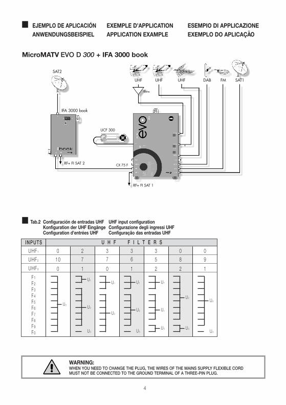
� EJEMPLO DE APLICACIÓN EXEMPLE D’APPLICATION ESEMPIO DI APPLICAZIONEANWENDUNGSBEISPIEL APPLICATION EXAMPLE EXEMPLO DO APLICAÇAO
MicroMATV EVO D 300 + IFA 3000 book
WARNING:WHEN YOU NEED TO CHANGE THE PLUG, THE WIRES OF THE MAINS SUPPLY FLEXIBLE CORDMUST NOT BE CONNECTED TO THE GROUND TERMINAL OF A THREE-PIN PLUG.
UHF
UCF 300
UHF UHF DAB FM SAT1
SAT2
CX 75 F
RF+ FI SAT 1
RF+ FI SAT 2
@ktive
IFA 3000 book
5
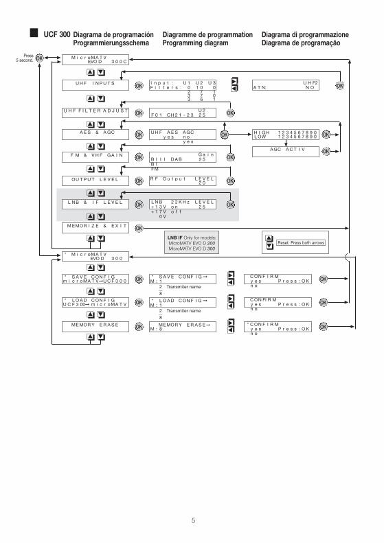
� UCF 300 Diagrama de programación Diagramme de programmation Diagrama di programmazioneProgrammierungsschema Programming diagram Diagrama de programação
�� ��
�� ��
��
OK
OK
OK
OK
OK
OK
OK
OK
OK
OK
OK
OK
OK
OK
OK
OKOK
I n p u t : U 1 U 2 U 3F i l t e r s : 0 1 0 0
2 7 13 7 03 6 1
UH F A E S AGCy e s n o
y e s
G a i nB I I I D AB 2 5B IFM
R F O u t p u t L E V E L2 0
L N B 2 2 K H z L E V E L+ 1 3 V o n 2 5+ 1 7 V o f f
0 V
* S A V E CON F I G �M : 1
2...8
* L OAD CON F I G �M : 1
2...8
CON F I R My e s P r e s s : O Kn o
CON FI R My e s P r e s s : O Kn o
Reset: Press both arrowsLNB IF Only for models:MicroMATV EVO D 200MicroMATV EVO D 300
Transmiter name
Transmiter name
��
�� ��
�� ��
�� ��
�� ��
�� ��
�� ��
����
����
����
����
�� ��
�� ��
OKOK MEMORY E R A S E�M : 8
* CON F I R My e s P r e s s : O Kn o
����
Press 5 second.
A E S & AGC
U 2F 0 1 CH 2 1 - 2 3 2 5
F M & V H F GA I N
OU T PU T L E V E L
L NB & I F L E V E L
MEMOR I Z E & E X I T
* M i c r oMA T VEVO D 3 0 0
* S A V E CON F I Gm i c r oMA T V�UC F 3 0 0
* L OAD CON F I GU C F 3 00� m i c r oMA T V
MEMORY E R A S E
UH F I NPU T S
M i c r oMA T VEVO D 3 0 0 C
U H F F I L T E R A D J U S T
�� ��
U H F2A T N: N O
OK
OKAGC AC T I V
H I GH 1 2 3 4 5 6 7 8 9 0LOW 1 2 3 4 5 6 7 8 9 0OK
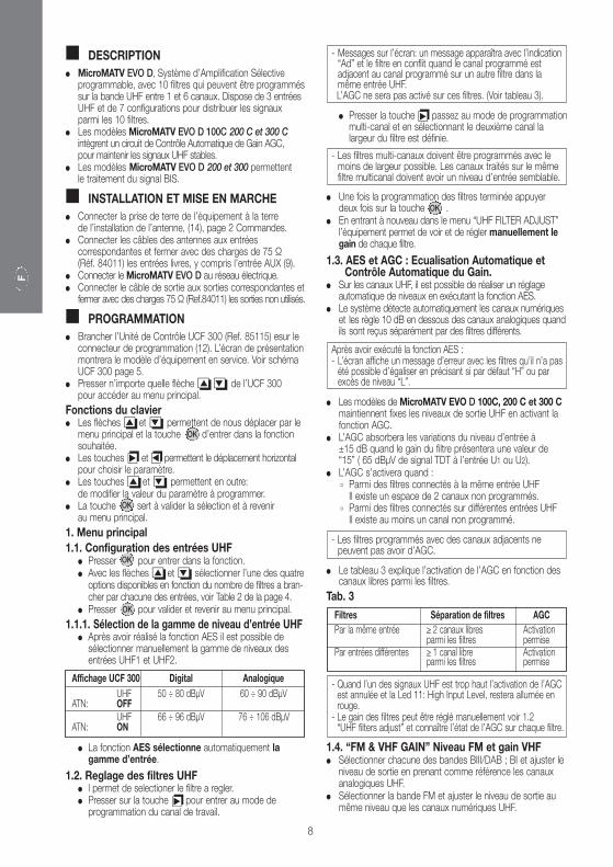
� DESCRIPCIÓN � MicroMATV EVO D, Sistema de Amplificación Selectivo
programable, con 10 filtros que pueden ser programadosen la banda de UHF entre 1 y 6 canales. Dispone de 3entradas de UHF y 7 configuraciones para distribuir las señales entre los 10 filtros.
� Los modelos MicroMATV EVO D 100C 200 C y 300 C incorporan circuito de Control Automático de Ganancia AGC, para mantener estables las señales de UHF.
� Los modelos MicroMATV EVO D 200 y 300 permitenla amplificación de la señal de 1ª FI SAT.
� INSTALACIÓN Y PUESTA EN MARCHA� Conectar la toma de tierra del equipo a la tierra de la
instalación de la antena, (14), pag 2 Controles.� Conectar los cables de las antenas en las entradas
correspondientes y cerrar con cargas de 75 Ω (Ref. 84011)las entradas libres, incluida la entrada AUX (9).
� Conectar el MicroMATV EVO D a la red eléctrica.� Conectar los cables de salida en las salidas correspondientes
y cerrar con cargas de 75 Ω (Ref. 84011) las salidas no utilizadas.
� PROGRAMACIÓN� Se conecta la Unidad de Control UCF 300 (Ref. 85115) en
el conector de programación (12). El display visualiza la pantalla de presentación con el modelo del equipo. Ver diagrama UCF 300 pag. 5.
� Pulsando cualquiera de las flechas �� �� de la UCF 300 se accede al menú principal.
Funciones del teclado� Con las flechas �� y �� nos movemos por el Menú
principal y con la tecla central entramos y salimos en la función deseada.
� Las flechas y permiten el desplazamiento horizontal para seleccionar el parámetro.
� Las flechas �� y �� permiten además:modificar el valor del parámetro a programar.
� La tecla sirve para validar y volver al menú principal.
1. Menú principal1.1. Configuración de entradas de “UHF INPUTS”
� Pulsar para entrar en la función.� Con las flechas �� y �� se selecciona una de las
siete opciones en función del número de filtros conectados en cada entrada, ver Tabla 2 de la pág. 4.
� Pulsar para validar y regresar al menú principal.
1.1.1. Selección del Rango de niveles de entrada UHF� Después de realizar la función AES se puede seleccionar
manualmente el rango de niveles de las entradas UHF1 y UHF2.
� La función AES selecciona automáticamente el rango de entrada.
1.2. Ajustes en los filtros de UHF� Permite la selección del filtro a ajustar.� Pulsando la flecha se entra en el modo de
programación del canal de trabajo.
Display UCF 300 Digital AnalogicoUHF 50 ÷ 80 dBµV 60 ÷ 90 dBµV
ATN: OFFUHF 66 ÷ 96 dBµV 76 ÷ 106 dBµV
ATN: ON
6
E
� Pulsando la flecha se pasa al modo de programación multi-canal y al seleccionar el segundo canal se define la anchura del filtro.
� Una vez terminada la programación de los filtros se pulsa la tecla dos veces.
� Al volver a entrar en el menú “UHF FILTER ADJUST” el equipopermite ver y ajustar manualmente la ganancia de cada filtro.
1.3. AES y AGC: Sistema de Ecualización Automática y Control Automático de Ganancia.
� Sobre los filtros de UHF se hace un ajuste automático de niveles ejecutando la función AES.
� El sistema detecta automáticamente los canales digitales y los ajusta 10 dB por debajo de los analógicos cuando se reciban individualmente por filtros diferentes.
� Los modelos de MicroMATV EVO D 100C, 200 C y 300 Cmantienen fijos los niveles de salida de UHF activando la función AGC.
� El AGC absorberá las variaciones del nivel de entrada en ±15 dB cuando la ganancia del filtro presente un valor de “15” ( 65 dBµV de señal TDT en la entrada U1 ó U2).
� El AGC se activará cuando:’ Entre filtros conectados a la misma entrada de UHF
exista un hueco de 2 canales sin programar.’ Entre filtros conectados a diferentes entradas de UHF
exista al menos 1 canal sin programar.
� La tabla 3 explica la activación del AGC en función de los canales libres entre filtros.
Tab. 3
1.4. “FM & VHF GAIN” Nivel FM y ganancia VHF � Seleccionar cada una de las bandas BIII/DAB; BI y ajustar
el nivel de salida tomando como referencia los canales analógicos de UHF.
� Seleccionar la banda FM y ajustar el nivel de salida al mismonivel que los canales digitales de UHF.
- Los filtros multi-canales deben programarse con la mínima anchura posible. Los canales procesados en el mismo filtro multicanal deben tener un nivel de entrada similar.
- Mensajes en el display: Aparecerá un mensaje con la indicación“Ad” y el filtro en conflicto cuando el canal programado sea adyacente con el canal programado en otro filtro de la misma entrada de UHF. El AGC no se activará en estos filtros. (Ver tabla 3).
Después de ejecutar la función AES:- El equipo mostrará una pantalla con la información de los filtros
que no ha sido posible igualar indicando si por exceso “H” o por falta de nivel “L”.
OK
OK
OK
OK
�� ��
- Cuando alguna de las señales de UHF sea demasiado alta se anula la activación del AGC y el Led 11: High Input Level, permanecerá encendido en rojo.
- Se puede ajustar manualmente la ganancia de los filtros ver 1.2 “UHF filters adjust” y conocer el estado del AGC en cada filtro.
Filtros Separación de filtros AGCPor la misma entrada ≥ 2 canales libres Activación
entre filtros permitidaPor entradas diferentes ≥ 1 canal libre Activación
entre filtros permitida
OK
��
��
- Los filtros programados con canales adyacentes no pueden tener AGC.
E
7
1.5. “OUTPUT LEVEL” Nivel de salida� Ajustar el nivel de salida deseado teniendo en cuenta el
nivel máximo de salida y el número total de canales de UHF, más BIII, más BI, más la entrada AUX, ver Tabla 4 y 5.
1.6. “LNB & IF LEVEL” Ajustes de la LNB y 1ª FI SAT(MicroMATV EVO D 200 y 300)
� Permite seleccionar la tensión deseada para la LNB: 0V,+13V y +17V.
� Pulsar la flecha para entrar en la selección de 0/22 KHz.
� Ajustar el nivel de salida de 1ª FI SAT teniendo en cuenta el nivel máximo y el número de transpondedores, ver Tabla 5. Hay que medir la potencia en el transpondedor de mayor nivel de salida. El transpondedor de 970 MHz debe estar al mismo nivel que los canales digitales de UHF.
1.7. Memorizar y salir “MEMORIZE & EXIT”� Pulsar la tecla para memorizar y regresar a la pantalla
de presentación.
� MicroMATV EVO D memoriza automáticamente los datos programados después de 3 minutos de haber pulsado la última tecla.
2. Menú extendido “ * MicroMATV EVO D”
� Desde la pantalla de presentación mantener pulsada la tecla durante 5 segundos, el display presenta el signo “ * ” en la esquina izquierda cuando se entra en esta función: “ * MicroMATV EVO D xxx”.
2.1. Guardar Configuración “ * SAVE CONFIG”� La Unidad de Control UCF 300 permite guardar 26
configuraciones e identificarlas con un nombre de12 caracteres.
� Para guardar una configuración ésta debe estar previamentememorizada en el MicroMATV EVO D (ver punto 1.7).
2.2. Cargar Configuración “ * LOAD CONFIG”� La Unidad de Control UCF 300 permite copiar cualquier
configuración memorizada y programarla en otro MicroMATV EVO D.
2.3. Borrar Memoria “ * MEMORY ERASE”� La Unidad UCF 300 permite borrar una a una las
configuraciones memorizadas.
3. Reset� Pulsando simultáneamente las flechas �� y �� se activa
la función RESET para borrar la programación: Filtros amplificadores a mínima ganancia, configuración de entradasUHF en 0 – 10 – 0, filtros de UHF sin canal programado, entrada de 1ª FI SAT sin tensión de salida para LNB (modelos MicroMATV EVO D 200 y 300) y la ganancia del amplificador de salida al máximo.
Tab. 4
Tab. 5
6. Problemas y Causa posible
NO ABRIR EL EQUIPO SIN DESCONECTAR DE LA RED ELÉCTRICA.
Nº de canales analógicos 2 4 5 6 8 16 24 32
Reducción de nivel de salida dB 0 -3 -4 -5 -6 -9 -11 -12
Nº de canales digitales /transpondedores 2 4 5 6 8 16 24 32
Reducción de nivel de salida dB -3 -6 -7 -8 -9 -12 -14 -15
OK
OK
��
Efecto
No permite ajustar laganancia de un filtro.
No se guarda en elUCF 300 la mismaconfiguración que estáen funcionamientoprogramada enMicroMATV EVO D.
Mala calidad de salidaen todos los canales.
El AGC no se activaen algunos filtros.
El AGC no se activa.Led de nivel de entradaalto encendido.
Led de nivel de entradaalto está encendido.
Indica nivel bajo “L”en un filtro pero elnivel de señal deentrada es correcto.
Causa posible
No se ha realizado elAES.
La configuración programada no se hamemorizado en elMicroMATV EVO D.
Nivel de entrada muyalto.
Exceso de nivel desalida.
Insuficiente separaciónentre filtros.
Nivel de entrada deUHF demasiado bajo.
Nivel de entrada deUHF demasiado alto.
Señales con nivelesalto en otros filtrosconectados a lamisma entrada UHF.
Acción
Ver el punto 1.3 delmanual.
Ejecutar el punto 1.7del manual.
Ver niveles de entradaen CaracterísticasPrincipales, pag.2 delmanual.
Ver el punto 1.2 y 1.5del manual y cumplirlos valores de la Tabla 5
Ver el punto 1.3 delmanual y Tab.3.
Ver niveles de entradaen CaracterísticasPrincipales, pag 2 delmanual.
Repartir la señal deantena y conectar elfiltro en la entrada deUHF donde no seprocesen las señalescon nivel alto.
SOLO PARA USO INTERIOR.
� UCF 300
OK
Adyacentecon Filtro 1
Nº Filtro Canal
Activaciónde AGC no
Entrada
Adj02 AGC: N U2ATF01 CH24 30
Ganancia
Rango UHF
F
� DESCRIPTION � MicroMATV EVO D, Système d’Amplification Sélective
programmable, avec 10 filtres qui peuvent être programméssur la bande UHF entre 1 et 6 canaux. Dispose de 3 entréesUHF et de 7 configurations pour distribuer les signaux parmi les 10 filtres.
� Les modèles MicroMATV EVO D 100C 200 C et 300 C intègrent un circuit de Contrôle Automatique de Gain AGC,pour maintenir les signaux UHF stables.
� Les modèles MicroMATV EVO D 200 et 300 permettent le traitement du signal BIS.
� INSTALLATION ET MISE EN MARCHE� Connecter la prise de terre de l’équipement à la terre
de l’installation de l’antenne, (14), page 2 Commandes.� Connecter les câbles des antennes aux entrées
correspondantes et fermer avec des charges de 75 Ω (Réf. 84011) les entrées livres, y compris l’entrée AUX (9).
� Connecter le MicroMATV EVO D au réseau électrique.� Connecter le câble de sortie aux sorties correspondantes et
fermer avec des charges 75 Ω (Ref.84011) les sorties non utilisés.
� PROGRAMMATION� Brancher l’Unité de Contrôle UCF 300 (Ref. 85115) esur le
connecteur de programmation (12). L’écran de présentationmontrera le modèle d’équipement en service. Voir schéma UCF 300 page 5.
� Presser n’importe quelle flèche �� �� de l’UCF 300 pour accéder au menu principal.
Fonctions du clavier� Les flèches �� et �� permettent de nous déplacer par le
menu principal et la touche d’entrer dans la fonction souhaitée.
� Les touches et permettent le déplacement horizontalpour choisir le paramètre.
� Les touches �� et �� permettent en outre:de modifier la valeur du paramètre à programmer.
� La touche sert à valider la sélection et à revenir au menu principal.
1. Menu principal1.1. Configuration des entrées UHF
� Presser pour entrer dans la fonction.� Avec les flèches �� et �� sélectionner l’une des quatre
options disponibles en fonction du nombre de filtres a bran-cher par chacune des entrées, voir Table 2 de la page 4.
� Presser pour valider et revenir au menu principal.
1.1.1. Sélection de la gamme de niveau d’entrée UHF � Après avoir réalisé la fonction AES il est possible de
sélectionner manuellement la gamme de niveaux des entrées UHF1 et UHF2.
� La fonction AES sélectionne automatiquement la gamme d’entrée.
1.2. Reglage des filtres UHF� l permet de selectioner le filtre a regler.� Presser sur la touche pour entrer au mode de
programmation du canal de travail.
� Presser la touche passez au mode de programmationmulti-canal et en sélectionnant le deuxième canal la largeur du filtre est définie.
� Une fois la programmation des filtres terminée appuyer deux fois sur la touche .
� En entrant à nouveau dans le menu “UHF FILTER ADJUST” l’équipement permet de voir et de régler manuellement le gain de chaque filtre.
1.3. AES et AGC : Ecualisation Automatique et Contrôle Automatique du Gain.
� Sur les canaux UHF, il est possible de réaliser un réglage automatique de niveaux en exécutant la fonction AES.
� Le système détecte automatiquement les canaux numériques et les règle 10 dB en dessous des canaux analogiques quand ils sont reçus séparément par des filtres différents.
� Les modèles de MicroMATV EVO D 100C, 200 C et 300 Cmaintiennent fixes les niveaux de sortie UHF en activant la fonction AGC.
� L’AGC absorbera les variations du niveau d’entrée à ±15 dB quand le gain du filtre présentera une valeur de “15” ( 65 dBµV de signal TDT à l’entrée U1 ou U2).
� L’AGC s’activera quand :’ Parmi des filtres connectés à la même entrée UHF
Il existe un espace de 2 canaux non programmés.’ Parmi des filtres connectés sur différentes entrées UHF
Il existe au moins un canal non programmé.
� Le tableau 3 explique l’activation de l’AGC en fonction des canaux libres parmi les filtres.
Tab. 3
1.4. “FM & VHF GAIN” Niveau FM et gain VHF � Sélectionner chacune des bandes BIII/DAB ; BI et ajuster le
niveau de sortie en prenant comme référence les canaux analogiques UHF.
� Sélectionner la bande FM et ajuster le niveau de sortie au même niveau que les canaux numériques UHF.
- Les filtres multi-canaux doivent être programmés avec le moins de largeur possible. Les canaux traités sur le même filtre multicanal doivent avoir un niveau d’entrée semblable.
- Les filtres programmés avec des canaux adjacents ne peuvent pas avoir d’AGC.
- Messages sur l’écran: un message apparaîtra avec l’indication“Ad” et le filtre en conflit quand le canal programmé est adjacent au canal programmé sur un autre filtre dans la même entrée UHF.L’AGC ne sera pas activé sur ces filtres. (Voir tableau 3).
Après avoir exécuté la fonction AES :- L’écran affiche un message d’erreur avec les filtres qu’il n’a pas
été possible d’égaliser en précisant si par défaut “H” ou par excès de niveau “L”.
OK
OK
OK
OK
�� ��
- Quand l’un des signaux UHF est trop haut l’activation de l’AGC est annulée et la Led 11: High Input Level, restera allumée en rouge.
- Le gain des filtres peut être réglé manuellement voir 1.2 “UHF filters adjust” et connaître l’état de l’AGC sur chaque filtre.
Filtres Séparation de filtres AGCPar la même entrée ≥ 2 canaux libres Activation
parmi les filtres permisePar entrées différentes ≥ 1 canal libre Activation
parmi les filtres permise
OK
��
��
8
Affichage UCF 300 Digital AnalogiqueUHF 50 ÷ 80 dBµV 60 ÷ 90 dBµV
ATN: OFFUHF 66 ÷ 96 dBµV 76 ÷ 106 dBµV
ATN: ON
F
9
1.5. “OUTPUT LEVEL” Niveau de sortie� Régler le niveau de sortie souhaite en tenant compte
du niveau de sortie et du nombre total de canaux UHF + BIII + BI + AUX, voir Table 4 et 5.
1.6. “LNB & IF LEVEL” Reglage LNB et BIS(MicroMATV EVO D 200 et 300)
� Il permet de sélectionner la tension nécessaire pour la LNB : 0V, 13V et +17V.
� Presser la touche pour entrer dans la sélection de 0 / 22 KHz.
� Ajuster le niveau de sortie BIS en tenant compte du niveau maximum et du nombre de transpondeurs, voir Table 5. Il est nécessaire de mesurer la puissance sur le transpondeur a plushaut niveau de sortie. Le transpondeur de 970 MHz doit êtreau même niveau que les canaux numériques UHF.
1.7. Enregistrer et quitter “MEMORIZE & EXIT”� Presser la touche pour enregister et revenir sur
l’écran de présentation.
� MicroMATV EVO D enregistre automatiquement les données programmées 6 minutes après la pression de la dernière touche.
2. Menu élargi “ * MicroMATV EVO D”
� Depuis l’écran de présentation, maintenir pressée pendant 5 seconds la touche ; l’écran montrera le signe “*” sur le coin gauche quand nous sommes dans cette fonction “ * MicroMATV EVO D xxx”.
2.1. Sauvegarder Configuration “ * SAVE CONFIG”� L’Unité de Contrôle UCF 300 permet de garder en mémoire 26
configurations en les identifiant avec un nom de 12 caractères.
� La configuration devra d’avance être garde dans la mémoire du MicroMATV EVO D (voir point 1.7).
2.2. Charger Configuration “ * LOAD CONFIG”� L’Unité de Contrôle UCF 300 permet de copier toutes les
configurations enregistres et les programmer sur un autreMicroMATV EVO D.
2.3. Effacer mémoire “ * MEMORY ERASE”� L’Unité de Commande UCF 300 permet d’effacer une à
une les configurations enregistrées.
3. Reinitialisation� Presser simultanément sur les touches �� et �� la
fonction RESET s’active pour effacer la programmation et la laisser selon celle d’origine: Amplificateurs large bande a gain mini, configuration des entrées en 0-10-0, filtres UHF sans canaux programmes, entrée BIS sans tension de sortie pour l’LNB (modèles MicroMATV EVO D 200 et 300) et l’amplificateur de sortie au maximum.
Tab. 4
Tab. 5
6. Problèmes et possibles causes
RISQUE DE CHOC ELECTRIQUE. NE PAS OUVRIR.
Nº de canaux analogiques 2 4 5 6 8 16 24 32
Réduction de niveau de sortie dB 0 -3 -4 -5 -6 -9 -11 -12
Nº de canaux numériques /transpondedores 2 4 5 6 8 16 24 32
Réduction de niveau de sortie dB -3 -6 -7 -8 -9 -12 -14 -15
OK
OK
��
Effet
Impossible de régler legain d’un filtre.
L’UCF 300 n’enregistrepas le paramétragede canaux program-mé sur le MicroMATVEVO D.
Mauvaise qualité desortie sur tous lescanaux.
L’AGC ne s’active passur certains filtres.
L’AGC ne s’active pas.Led de niveau d’entréeélevé allumé.
Led de niveau d’entréeélevé allumé.
Indique niveau bas “L” sur un filtre maisniveau de signal l’entrée est correct.
Cause possible
L’AES n’a pas étéréalisé.
Le paramétrage pro-grammé n’a pas étéenregistré par leMicroMATV EVO D.
Niveau d’entrée trèsélevé.
Excès de niveau desortie.
Séparation insuffisanteentre les filtres.
Niveau d’entréeUHF trop bas.
Niveau d’entréeUHF trop élevé.
Signaux avec niveauxélevé sur d’autres filtres déconnecté àmême entrée UHF.
Action
Voir le point 1.3. dumanuel.
Exécuter le point 1.7.du manuel.
Voir niveaux d’entréeà Principales caracté-ristiques, page 2 dumanuel.
Voir les points 1.2. et 1.5.du manuel et respecterles valeurs de la Table 5
Voir le point 1.3. dumanuel et Tab.3.
Voir niveaux d’entréeà Principales caracté-ristiques, page 2 dumanuel.
Répartir le signald’antenne et connecterle filtre à l’entrée UHFoù les signaux avecun niveau élevés nesont pas traités.
POUR USAGE A L’INTERIOR SEULAMENT.
� UCF 300
OK
Adjacentavec Filtre 1
Nº Filtre Canal
Activationd’AGC no
Entrée
Adj02 AGC: N U2ATF01 CH24 30
Gain
Gamme UHF
UK
10
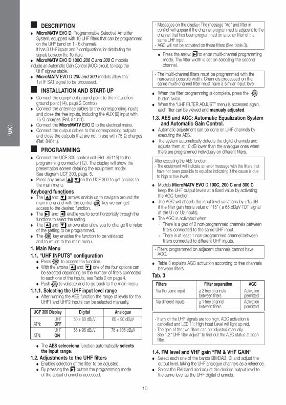
� DESCRIPTION � MicroMATV EVO D, Programmable Selective Amplifier
System, equipped with 10 UHF filters that can be programmedon the UHF band on 1 - 6 channels. It has 3 UHF inputs and 7 configurations for distributing the signals between the 10 filters.
� MicroMATV EVO D 100C 200 C and 300 C modelsinclude an Automatic Gain Control (AGC) circuit, to keep the
UHF signals stable.� MicroMATV EVO D 200 and 300 models allow the
1st IF SAT signal to be processed.
� INSTALLATION AND START-UP� Connect the equipment ground point to the installation
ground point (14), page 2 Controls.� Connect the antennae cables to the corresponding inputs
and close the free inputs, including the AUX (9) input with 75 Ω charges (Ref. 84011).
� Connect the MicroMATV EVO D to the electrical mains.� Connect the output cables to the corresponding outputs
and close the outputs that are not in use with 75 Ω charges(Ref. 84011).
� PROGRAMMING� Connect the UCF 300 control unit (Ref. 85115) to the
programming connector (12). The display will show the presentation screen detailing the equipment model. See diagram UCF 300, page. 5.
� Press any arrow �� �� on the UCF 300 to get access to the main menu.
Keyboard functions� The �� and �� arrows enable us to navigate around the
main menu and with the central key we can get access to the desired function.
� The and enable you to scroll horizontally through the functions to select the setting.
� The �� and �� arrows also allow you to change the valueof the setting to be programmed.
� The key enables the function to be validated and to return to the main menu.
1. Main Menu1.1. “UHF INPUTS” configuration
� Press to access the function.� With the arrows �� and �� one of the four options can
be selected depending on the number of filters connected to each one of the inputs, see Table 2 on page 4.
� Push to validate and to go back to the main menu.
1.1.1. Selecting the UHF input level range� After running the AES function the range of levels for the
UHF1 and UHF2 inputs can be selected manually.
� The AES selecciona function automatically selects the input range.
1.2. Adjustments to the UHF filters� Enables selection of the filter to be adjusted.� By pressing the button the programming mode
of the actual channel is accessed.
UCF 300 Display Digital AnalogueUHF 50 ÷ 80 dBµV 60 ÷ 90 dBµV
ATN: OFFUHF 66 ÷ 96 dBµV 76 ÷ 106 dBµV
ATN: ON
� Press the arrow to enter multi-channel programming mode. The filter width is set on selecting the second channel.
� When the filter programming is complete, press the button twice.
� When the “UHF FILTER ADJUST” menu is accessed again, each filter can be viewed and manualy adjusted.
1.3. AES and AGC: Automatic Equalization System and Automatic Gain Control.
� Automatic adjustment can be done on UHF channels by executing the AES.
� The system automatically detects the digital channels and adjusts them at 10 dB lower than the analogue ones when there are programmed individualy on different filters.
� Models MicroMATV EVO D 100C, 200 C and 300 Ckeep the UHF output levels at a fixed value by activating the AGC function.
� The AGC will absorb the input level variations by ±15 dB if the filter gain has a value of “15” ( a 65 dBµV TDT signal at the U1 or U2 inputs).
� The AGC is activated when:’ There is a gap of 2 non-programmed channels between
filters connected to the same UHF input.’ There is at least 1 non-programmed channel between
filters connected to different UHF inputs.
� Table 3 explains AGC activation according to free channels between filters.
Tab. 3
1.4. FM level and VHF gain “FM & VHF GAIN”� Select each one of the bands BIII/DAB; BI and adjust the
output level, taking the UHF analogue channels as a reference.� Select the FM band and adjust the desired output level to
the same level as the UHF digital channels.
- The multi-channel filters must be programmed with the narrowest possible width. Channels processed on the same multi-channel filter must have a similar input level.
- Filters programmed on adjacent channels cannot have AGC.
- Messages on the display: The message “Ad” and filter in conflict will appear if the channel programmed is adjacent to thechannel that has been programmed on another filter of the same UHF input.
- AGC will not be activated on these filters (See table 3).
After executing the AES function:- The equipment will indicate an error message with the filters that
have not been possible to equalise indicating if the cause is dueto high or low levels.
OK
OK
OK
OK
�� ��
- If any of the UHF signals are too high, AGC activation is cancelled and LED 11: High Input Level will light up red.
- The gain of the two filters can be adjusted manually. See 1.2 “UHF filter adjust” to find out the AGC status at eachfilter.
Filters Filter separation AGCVia the same input ≥ 2 free channels Activation
between filters permittedVia different inputs ≥ 1 free channel Activation
between filters permitted
OK
��
��
UK
11
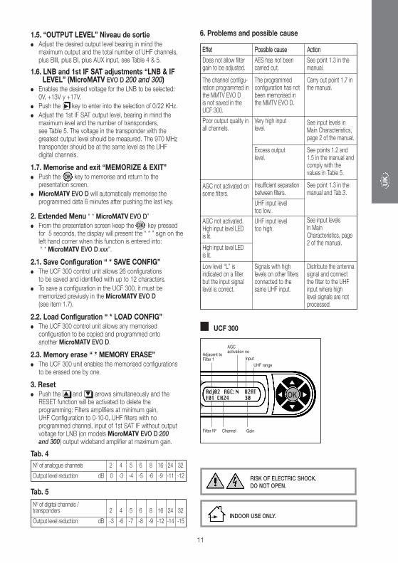
1.5. “OUTPUT LEVEL” Niveau de sortie� Adjust the desired output level bearing in mind the
maximum output and the total number of UHF channels, plus BIII, plus BI, plus AUX input, see Table 4 & 5.
1.6. LNB and 1st IF SAT adjustments “LNB & IF LEVEL” (MicroMATV EVO D 200 and 300)
� Enables the desired voltage for the LNB to be selected: 0V, +13V y +17V.
� Push the key to enter into the selection of 0/22 KHz.
� Adjust the 1st IF SAT output level, bearing in mind the maximum level and the number of transponders, see Table 5. The voltage in the transponder with the greatest output level should be measured. The 970 MHz transponder should be at the same level as the UHF digital channels.
1.7. Memorise and exit “MEMORIZE & EXIT”� Push the key to memorise and return to the
presentation screen.
� MicroMATV EVO D will automatically memorise the programmed data 6 minutes after pushing the last key.
2. Extended Menu “ * MicroMATV EVO D”
� From the presentation screen keep the key pressed for 5 seconds, the display will present the “ * ” sign on the left hand corner when this function is entered into: “ * MicroMATV EVO D xxx”.
2.1. Save Configuration “ * SAVE CONFIG”� The UCF 300 control unit allows 26 configurations
to be saved and identified with up to 12 characters.
� To save a configuration in the UCF 300, it must be memorized previusly in the MicroMATV EVO D(see item 1.7).
2.2. Load Configuration “ * LOAD CONFIG”� The UCF 300 control unit allows any memorised
configuration to be copied and programmed onto another MicroMATV EVO D.
2.3. Memory erase “ * MEMORY ERASE”� The UCF 300 unit enables the memorised configurations
to be erased one by one.
3. Reset� Push the �� and �� arrows simultaneously and the
RESET function will be activated to delete the programming: Filters amplifiers at minimum gain, UHF Configuration to 0-10-0, UHF filters with no programmed channel, input of 1st SAT IF without output voltage for LNB (on models MicroMATV EVO D 200 and 300) output wideband amplifier at maximum gain.
Tab. 4
Tab. 5
6. Problems and possible cause
RISK OF ELECTRIC SHOCK. DO NOT OPEN.
Nº of analogue channels 2 4 5 6 8 16 24 32
Output level reduction dB 0 -3 -4 -5 -6 -9 -11 -12
Nº of digital channels /transponders 2 4 5 6 8 16 24 32
Output level reduction dB -3 -6 -7 -8 -9 -12 -14 -15
OK
OK
��
Effet
Does not allow filtergain to be adjusted.
The channel configu-ration programmed inthe MMTV EVO D is not saved in theUCF 300.
Poor output quality inall channels.
AGC not activated onsome filters.
AGC not activated.High input level LED is lit.
High input level LED is lit.
Low level “L” isindicated on a filterbut the input signallevel is correct.
Possible cause
AES has not beencarried out.
The programmedconfiguration has notbeen memorised inthe MMTV EVO D.
Very high input level.
Excess output level.
Insufficient separationbetween filters.
UHF input level too low.
UHF input level too high.
Signals with highlevels on other filtersconnected to thesame UHF input.
Action
See point 1.3 in themanual.
Carry out point 1.7 inthe manual.
See input levels inMain Characteristics,page 2 of the manual.
See points 1.2 and1.5 in the manual andcomply with thevalues in Table 5.
See point 1.3 in themanual and Tab.3.
See input levels in MainCharacteristics, page2 of the manual.
Distribute the antennasignal and connectthe filter to the UHFinput where high level signals are notprocessed.
INDOOR USE ONLY.
� UCF 300
OK
Adjacent toFilter 1
Filter Nº Channel
AGC activation no
Input
Adj02 AGC: N U2ATF01 CH24 30
Gain
UHF range
I
12
� DESCRIZIONE� MicroMATV EVO D, Sistema di amplificazione selettivo
programmabile, con 10 filtri UHF che possono essere programmati nella banda UHF fra 1 e 6 canali. Ha 3 ingressi UHF e 7 configurazioni per distribuire i segnali tra i 10 filtri.
� I modelli MicroMATV EVO D 100C 200 C e 300 Cincludono un circuito di Controllo Automatico di Guadagno AGC,per mantenere stabili i segnali UHF.
� I modelli MicroMATV EVO D 200 and 300 models allow the 1st IF SAT signal to be processed.
� INSTALLAZIONE E AVVIO� Collegare la messa a terra dell’apparecchiatura alla terra
dell’impianto (14), pag 2 Comandi.� Collegare i cavi dell’antenne agli ingressi corrispondenti
e chiudere con carichi di 75 Ω (Rif. 84011) gli ingressi liberi, compreso l’ingresso AUX (9).
� Collegare il MicroMATV EVO D alla rete elettrica.� Collegare i cavi di uscita alle uscite corrispondenti e chiudere
con cariche di 75 Ω (Rif. 84011) le uscite libere.
� PROGRAMMAZIONE� Si collega l’Unità di comando UCF 300 (Rif. 85115) sul
connettore di programmazione (12). Il display visualizza la schermata di presentazione con il modello di apparecchiatura.V. schema UCF300 pag. 5.
� Premendo qualsiasi freccia �� �� della UCF 300 si accede al menu principale.
Funzioni della tastiera� Con i tasti �� e �� ci si sposta lungo il Menu principale;
con il tasto al centro si entra e si esce dalla funzione desiderata.
� I tasti e consentono lo spostamento orizzontale per selezionare il parametro.
� I tasti �� e �� consentono inoltre di:modificare il valore del parametro da programmare.
� Premere il tasto per convalidare e tornare al menu principale.
1. Menu principale1.1. Configurazione “UHF INPUTS”
� Premere per accedere alla funzione.� Con i tasti �� e �� si seleziona una delle quattro opzioni
in funzione del numero di filtri collegati a ogni ingresso; v. Tabella 2 a pag. 4.
� Premere per confermare e tornare al menu principale.
1.1.1. Selezione dell’Intervallo di livelli di entrata UHF� Dopo aver realizzato la funzione AES si può selezionare
manualmente l’intervallo dei livelli delle entrate UHF1 UHF2.
� La funzione AES seleziona automaticamente l’intervallo di entrata.
1.2. Regolazioni sui filtri UHF� Permette la selezione del filtro da regolare.� Premendo il tasto si entra nella modalità
di programmazione del canale di esercizio.
Display UCF 300 Digitale AnalogicoUHF 50 ÷ 80 dBµV 60 ÷ 90 dBµV
ATN: OFFUHF 66 ÷ 96 dBµV 76 ÷ 106 dBµV
ATN: ON
� Premere il tasto si passa alla modalità di programma-zione multicanale e selezionando il secondo canale si definisce l’ampiezza del filtro.
� Una volta conclusa la programmazione dei filtri si preme il tasto due volte.
� Entrando di nuovo nel menù “UHF FILTER ADJUST” il dispositivo consente di vedere e regolare manualmente il guadagno di ogni filtro.
1.3. AES e AGC: Sistema di equalizzazione automaticae Controllo automatico del guadagno.
� Sui canali UHF è possibile eseguire una regolazione automaticadei livelli, lanciando la funzione AES.
� Il sistema rileva automaticamente i canali digitali e li imposta 10 dB al di sotto di quelli analogici quando si ricevono singolarmente tramite filtri diversi.
� I modeli MicroMATV EVOD 100C, 200 C e 300 Cmantengonofissi i livelli di uscita di UHF attivando la funzione AGC.
� L’AGC assorbirà le variazioni del livello di entrata di ±15 dBquando il guadagno del filtro presenta un valore “15” (65 dBµV di segnale TDT nell’entrata U1 o U2).
� L’AGC si attiverà quando:’ Tra filtri collegato alla stessa entrata UHF esiste un vuoto
di 2 canali non programmati.’ Tra filtri collegati a diverse entrate UHF esiste almeno
1 canale non programmato.
� La tabella 3 spiega l’attivazione dell’AGC in base ai canali liberi tra filtri.
Tab. 3
1.4. Livello FM e Guadagno VHF “FM UHF GAIN”� Selezionare ciascuna delle bande BIII; BI e regolare il livello
di uscita prendendo come riferimento il livello dei canali analogici UHF.
� Selezionare la banda FM e regolare il livello di uscita allo stesso livello dei canali digitali UHF.
- I filtri multi-canale si devono programmare con la minima ampiezza possibile. I canali elaborati nello stesso filtro multicanale devono avere un livello di entrata simile.
- I filtri programmati con canali adiacenti non possono avere AGC.
- Messaggio sul display: Apparirà un messaggio con l’indicazione“Ad” e il filtro in conflitto quando il canale programmato è adiacente al canale programmato in un altro filtro della stessa entrata UHF.L’AGC non si attiverà in questi filtri. (Vedi tabella 3).
Dopo aver eseguito la funzione AES:- L’apparecchiatura visualizzerà un messaggio di errore (“Error”)
con i filtri che non è stato possibile pareggiare, indicando se per eccesso “H” o per difetto di livello “L”.
OK
OK
OK
OK
�� ��
- Quando uno dei segnali UHF è troppo alto si annulla l’attivazione dell’AGC e il Led 11: High Input Level, rimane acceso in rosso.
- Si può regolare manualmente il guadagno dei filtri: vedi 1.2 “UHF filters adjust” e conoscere lo stato dell’AGC in ogni filtro.
Filtri Distanza filtri AGCDalla stessa entrata ≥ 2 canali liberi Attivazione
tra filtri consentitaDa entrate diverse ≥ 1 canale libero Attivazione
tra filtri consentita
OK
��
��
I
13
1.5. Livello di uscita “OUTPUT LEVEL”� Regolare il livello di uscita desiderato tenendo presente il
livello massimo di uscita e il numero totale di canali UHF, più BIII, più BI, più l’ingresso AUX (v. tabella 4 e 5).
1.6. Regolazioni della LNB e 1ª FI SAT “LNB & IF LEVEL” (MicroMATV EVO D 200 e 300)
� Consente di selezionare la tensione per la LNB: 0V,+13V y +17V.
� Premere il tasto per entrare in la selezione di 0/22 KHz.
� Regolare il livello di uscita di 1ª FI SAT, tenendo conto del livello massimo e del numero di transponder (vedi Tabella 5).Bisogna misurare la potenza del transponder di maggiore livello di uscita. Il transponder da 970 MHz deve essereallo stesso livello dei canali digitali UHF.
1.7. Memorizzare e uscire “MEMORIZE & EXIT”� Premere il tasto per memorizzare e tornare al menu
d’inizio.
� MicroMATV EVO D memorizza automaticamente i dati programmati 3 minuti dopo aver premuto l’ultimo tasto.
2. Menu esteso “ * MicroMATV EVO D”
� Dalla schermata iniziale, tenere premuto il tasto per 5 secondi; il display visualizza il segno “ * ” nell’angolo a sinistra quando si entra in questa funzione:“ * MicroMATV EVO D xxx”.
2.1. Salvare configurazione “ * SAVE CONFIG”� L’Unità di Controllo UCF 300 permette salvare 26 configurazioni
e di identificarle con un nome composto da 12 caratteri.
� Per salvare una configurazione, questa deve essere stata prima memorizzata in MicroMATV EVO D (v. punto 1.7).
2.2. Caricare configurazione “ * LOAD CONFIG”� L’Unità di controllo UCF 300 consente di copiare qualsiasi
configurazione memorizzata e di programmarla su un’altra MicroMATV EVO D.
2.3. Cancellare memoria “ * MEMORY ERASE”� L’Unità UCF 300 permette di cancellare una a una le
configurazioni memorizzate.
3. Reset� Premendo contemporaneamente le frecce �� e �� ,
si attiva la funzione RESET per cancellare la programmazione:Filtri amplificatori a guadagno minimo, configurazione degli ingressi UHF su 0-10-0, filtri UHF senza canali programmati, ingresso di 1ª FI SAT senza tensione di uscitaper LNB (modelli MicroMATV EVO D 200 e 300) e il guadagno dell’amplificatore di uscita al massimo.
Tab. 4
Tab. 5
6. Problemi e possibili cause
NON APRIRE L’APPARECCHIATURA SENZA AVER PRIMA SCOLLEGATO LARETE ELETTRICA.
Nº di canali analogici 2 4 5 6 8 16 24 32
Riduzione livelli di uscita dB 0 -3 -4 -5 -6 -9 -11 -12
Nº di canali digitali /transponders 2 4 5 6 8 16 24 32
Riduzione livelli di uscita dB -3 -6 -7 -8 -9 -12 -14 -15
OK
OK
��
Effetto
Non permette la regolazione del guadagno di un filtro.
Non si salva nell’UCF300 la configurazionedei canali programmatanella MMTV EVO D.
Scarsa qualità di uscita in tutti i canali.
L’AGC non si attiva inalcuni filtri.
L’AGC non si attiva.Led di livello di entrataalto acceso.
Led di livello di entrataalto è acceso.
Indica livello basso “L”in un filtro ma il livellodi segnale di entrata ècorretto.
Possibile causa
Non è stato eseguitol’AES.
La configurazione programmata non èstata memorizzata nellaMicroMATV EVO D.
Livello di ingressomolto alto.
Livello di uscitaeccessivo.
Insufficiente distanzatra filtri.
Livello di entrata UHFtroppo basso.
Livello di entrata UHFtroppo alto.
Segnali con livelli altiin altri filtri collegatialla stessa entrataUHF.
Azione
Vedere il punto 1.3 delmanuale.
Eseguire il punto 1.7del manuale.
Vedere livelli di ingressoin Caratteristiche principali, pag.2 delmanuale.
Vedere i punti 1.2 e1.5 del manuale eosservare i valori dellaTabella 5.
Vedere il punto 1.3 delmanuale e Tab.3.
Vedere livelli di ingressoin Caratteristiche principali, pag.2 del Manuale.
Distribuire il segnale diantenna e collegare ilfiltro all’entrata UHFdove non vengonoelaborati i segnali conlivello alto.
SOLO PER USO INTERNO.
� UCF 300
OK
Adiacentecon Filtro 1
Nº Filtro Canale
Attivazionedi AGC no
Entrata
Adj02 AGC: N U2ATF01 CH24 30
Guadagno
Intervallo UHF

JJK
/ FA
GO
R.
MIC
RO
MAT
V EV
O-D
/ 4
I /
1-18
Fagor Electrónica, S.Coop.San Andrés, s/n. P. O. Box 33E-20500 Mondragón (Spain)Tel. +34 943 712 526Fax +34 943 712 893E-mail: [email protected]
Declaration: https://www.fagorelectronica.com/es/recepcion-tv/productos