LOPES 3D reconfiguration and first measurements
4
32ND I NTERNATIONAL COSMIC RAY CONFERENCE,BEIJING 2011 LOPES 3D reconfiguration and first measurements D. HUBER 1 , W.D. APEL 2 , J.C. ARTEAGA 1,14 , L. B¨ AHREN 3 , K. BEKK 2 , M. BERTAINA 4 , P.L. BIERMANN 5 , J. BL ¨ UMER 1,2 , H. BOZDOG 2 , I.M. BRANCUS 6 , P. BUCHHOLZ 7 , E. CANTONI 4,8 , A. CHIAVASSA 4 , K. DAUMILLER 2 , V. DE SOUZA 1,15 , F. DI PIERRO 4 , P. DOLL 2 , R. ENGEL 2 , H. FALCKE 3,9,5 , M. FINGER 1 , B. FUCHS 1 , D. FUHRMANN 10 , H. GEMMEKE 11 , C. GRUPEN 7 , A. HAUNGS 2 , D. HECK 2 , J.R. H¨ ORANDEL 3 , A. HORNEFFER 5 , T. HUEGE 2 , P.G. I SAR 2,16 , K.-H. KAMPERT 10 , D. KANG 1 , O. KR ¨ OMER 11 , J. KUIJPERS 3 , K. LINK 1 , P. LUCZAK 12 , M. LUDWIG 1 , H.J. MATHES 2 , M. MELISSAS 1 , C. MORELLO 8 , J. OEHLSCHL ¨ AGER 2 , N. PALMIERI 1 , T. PIEROG 2 , J. RAUTENBERG 10 , H. REBEL 2 , M. ROTH 2 , C. R¨ UHLE 11 , A. SAFTOIU 6 , H. SCHIELER 2 , A. SCHMIDT 11 , F.G. SCHR ¨ ODER 2 , O. SIMA 13 , G. TOMA 6 , G.C. TRINCHERO 8 , A. WEINDL 2 , J. WOCHELE 2 , M. WOMMER 2 , J. ZABIEROWSKI 12 , J.A. ZENSUS 5 1 Institut f¨ ur Experimentelle Kernphysik, KIT - Karlsruher Institut f¨ ur Technologie, Germany 2 Institut f¨ ur Kernphysik, KIT - Karlsruher Institut f¨ ur Technologie, Germany 3 Radboud University Nijmegen, Department of Astrophysics, The Netherlands 4 Dipartimento di Fisica Generale dell’ Universit` a Torino, Italy 5 Max-Planck-Institut f¨ ur Radioastronomie Bonn, Germany 6 National Institute of Physics and Nuclear Engineering, Bucharest, Romania 7 Fachbereich Physik, Universit¨ at Siegen, Germany 8 Istituto di Fisica dello Spazio Interplanetario, INAF Torino, Italy 9 ASTRON, Dwingeloo, The Netherlands 10 Fachbereich Physik, Universit¨ at Wuppertal, Germany 11 Institut f¨ ur Prozessdatenverarbeitung und Elektronik, KIT - Karlsruher Institut f¨ ur Technologie, Germany 12 Soltan Institute for Nuclear Studies, Lodz, Poland 13 Department of Physics, University of Bucharest, Bucharest, Romania 14 now at: Univ Michoacana, Morelia, Mexico; 15 now at: Univ S˜ ao Paulo, Inst. de F´ ısica de S ˜ ao Carlos, Brasil; 16 now at: Inst. Space Sciences, Bucharest, Romania [email protected] Abstract: The study of cosmic rays at highest energies can only be done by observing air showers with large scale detector arrays on the ground. One detection technique is to observe the radio emission from the geomagnetic deflected charged particles in an air shower [1]. The LOPES experiment [2] at the Karlsruhe Institute of Technology (KIT) was the first experiment to measure this radio emission via digital interferometry. Since then LOPES was developed further and further [3]. In the present setup LOPES is consisting of 10 tripole antennas which allows to measure all three components of the electric field vector. This article shows the reconfiguration of LOPES to LOPES 3D and the calibration of the LOPES 3D experiment. Keywords: Radio detection LOPES calibration 1 Introduction The observation of cosmic rays with energies ≥ 10 17 eV is a challenging field of research. One has to go to extreme large detector arrays on the ground and to face several dif- ficulties in the reconstruction and the measurement itself. To gain the best results, different observation techniques have to be combined. The radio detection is a promising candidate to observe the air shower development, because all charged particles, especially e − and e + , get deflected in the Earth’s magnetic field and emit a radio signal. The radio detection is not absorbed in the atmosphere and only influenced by strong atmospheric electric fields like dur- ing thunderstorms. It is so far the only detection technique that combines a long up time and sensitivity to the shower development because it, in contrast to fluorescence mea- surements, can also measure at daytime [4]. Therefore it is desirable to fully exploit the potential of this detection technique. One advancement within this detection method is the vectorial measurement of radio emission. To study the feasibility of these vectorial measurements, the LOPES experiment was reconfigured to be now able to measure all three components of the electric field vector from the ra- dio emission of cosmic ray induced air showers and not
Transcript of LOPES 3D reconfiguration and first measurements
32ND INTERNATIONAL COSMIC RAY CONFERENCE, BEIJING 2011
LOPES 3D reconfiguration and first measurements
D. HUBER1, W.D. APEL2, J.C. ARTEAGA1,14 , L. BAHREN3 , K. BEKK2, M. BERTAINA4, P.L. BIERMANN5 ,J. BLUMER1,2, H. BOZDOG2 , I.M. BRANCUS6 , P. BUCHHOLZ7 , E. CANTONI4,8 , A. CHIAVASSA4 , K. DAUMILLER 2 ,V. DE SOUZA1,15 , F. DI PIERRO4 , P. DOLL2, R. ENGEL2, H. FALCKE3,9,5, M. FINGER1 , B. FUCHS1 ,D. FUHRMANN10 , H. GEMMEKE11, C. GRUPEN7 , A. HAUNGS2 , D. HECK2 , J.R. HORANDEL3, A. HORNEFFER5,T. HUEGE2, P.G. ISAR2,16, K.-H. KAMPERT10 , D. KANG1, O. KROMER11 , J. KUIJPERS3, K. L INK1 , P. ŁUCZAK12,M. L UDWIG1, H.J. MATHES2, M. MELISSAS1, C. MORELLO8, J. OEHLSCHLAGER2, N. PALMIERI 1 , T. PIEROG2 ,J. RAUTENBERG10 , H. REBEL2, M. ROTH2, C. RUHLE11, A. SAFTOIU6 , H. SCHIELER2, A. SCHMIDT11 ,F.G. SCHRODER2 , O. SIMA 13 , G. TOMA6, G.C. TRINCHERO8 , A. WEINDL2 , J. WOCHELE2, M. WOMMER2 ,J. ZABIEROWSKI12 , J.A. ZENSUS5
1 Institut fur Experimentelle Kernphysik, KIT - Karlsruher Institut fur Technologie, Germany2 Institut fur Kernphysik, KIT - Karlsruher Institut fur Technologie, Germany3 Radboud University Nijmegen, Department of Astrophysics,The Netherlands4 Dipartimento di Fisica Generale dell’ Universita Torino, Italy5 Max-Planck-Institut fur Radioastronomie Bonn, Germany6 National Institute of Physics and Nuclear Engineering, Bucharest, Romania7 Fachbereich Physik, Universitat Siegen, Germany8 Istituto di Fisica dello Spazio Interplanetario, INAF Torino, Italy9 ASTRON, Dwingeloo, The Netherlands10 Fachbereich Physik, Universitat Wuppertal, Germany11 Institut fur Prozessdatenverarbeitung und Elektronik, KIT - Karlsruher Institut fur Technologie, Germany12 Soltan Institute for Nuclear Studies, Lodz, Poland13 Department of Physics, University of Bucharest, Bucharest, Romania14 now at: Univ Michoacana, Morelia, Mexico;15 now at: Univ Sao Paulo, Inst. de Fısica de Sao Carlos, Brasil;16 now at: Inst. Space Sciences, Bucharest, Romania
Abstract: The study of cosmic rays at highest energies can only be done by observing air showers with large scaledetector arrays on the ground. One detection technique is toobserve the radio emission from the geomagnetic deflectedcharged particles in an air shower [1]. The LOPES experiment[2] at the Karlsruhe Institute of Technology (KIT) was thefirst experiment to measure this radio emission via digital interferometry. Since then LOPES was developed further andfurther [3]. In the present setup LOPES is consisting of 10 tripole antennas which allows to measure all three componentsof the electric field vector. This article shows the reconfiguration of LOPES to LOPES 3D and the calibration of theLOPES 3D experiment.
Keywords: Radio detection LOPES calibration
1 Introduction
The observation of cosmic rays with energies≥ 1017 eV isa challenging field of research. One has to go to extremelarge detector arrays on the ground and to face several dif-ficulties in the reconstruction and the measurement itself.To gain the best results, different observation techniqueshave to be combined. The radio detection is a promisingcandidate to observe the air shower development, becauseall charged particles, especiallye− ande
+, get deflectedin the Earth’s magnetic field and emit a radio signal. Theradio detection is not absorbed in the atmosphere and only
influenced by strong atmospheric electric fields like dur-ing thunderstorms. It is so far the only detection techniquethat combines a long up time and sensitivity to the showerdevelopment because it, in contrast to fluorescence mea-surements, can also measure at daytime [4]. Therefore itis desirable to fully exploit the potential of this detectiontechnique. One advancement within this detection methodis the vectorial measurement of radio emission. To studythe feasibility of these vectorial measurements, the LOPESexperiment was reconfigured to be now able to measure allthree components of the electric field vector from the ra-dio emission of cosmic ray induced air showers and not
D. HUBER et al. LOPES 3D
only a two dimensional projection. The achieved resultshave the potential to impact future experiments and analy-ses. LOPES once more acts as research and developmentarray for large scale applications.
2 Reconfiguration
2.1 Hardware
With the reconfiguration of LOPES to LOPES 3D somehardware changes had to be done e.g. the antenna typewas changed which made new preamplifier and new ca-bling necessary. The new hardware is discussed in detail inthe following paragraphs.
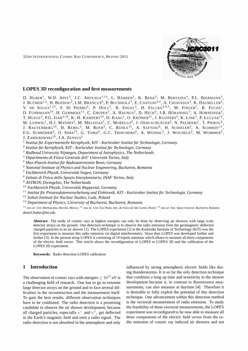
Figure 1: Picture of the tripole, the new antenna type usedat LOPES 3D. The metal box at the pole is the housing forthe preamplifier.
2.1.1 Antenna type
The antenna type used for LOPES 3D is a tripole, see figure1. This antenna consists of three crossed dipoles and cov-ers one channel per dipole, thus three channels per antenna.The tripole provides high sensitivity, a homogeneous setupand symmetrical characteristics for each channel. Havinghomogeneous and symmetrical antenna characteristics isessential for vectorial analyses and reduces the risk of sys-tematic errors.
2.1.2 Preamplifier
The low noise amplifiers (LNA) used for LOPES 3D wereoriginally designed for the Auger Engineering Radio Ar-ray AERA [5]. They provide low power consumption highstability and a very low noise level. Because they aretwo channel amplifiers one needs two amplifiers per tripolewhich results in one spare amplifier channel per tripole.
2.1.3 Beacon
The beacon is a reference emitter emitting sine waves. Itis needed to improve and monitor the timing of the experi-ment [6]. With the beacon a timing accuracy of1 ns whichis needed for digital interferometry is achieved. The phasedifferences of the signals from the beacon are constant dueto geometrical reasons. With the known phase differencesfrom the calibration and the actual measured ones the tim-ing can be monitored and if necessary corrected. In orderto be also seen in the new, vertical polarization, the beaconhad to be rotated and the emission power was increased.
2.2 Antenna positions
LOPES 3D has ten antenna positions, since the LOPESdata acquisition provides 30 channels and each tripole allo-cates three channels. For the new positions several aspectshad to be concerned:
• Cover a huge area.
• Avoid regularities since they lead to higher side lobes[7] when using LOPES 3D as digital radio interfer-ometer.
• Reuse of cables from the previous setup of LOPES.
• Reduce the effort and the danger of damaging thehardware during the reconfiguration by choosingantenna positions were old LOPES antennas werestanding.
The resulting layout can be seen in figure 2.
3 Calibration
After the reconfiguration a complete calibration needed tobe done. The single steps are explained in detail in thefollowing.
3.1 Measurement of the antenna positions
The requirement in the timing accuracy when using LOPES3D as digital radio interferometer is1 ns. This accuracy inthe timing can be converted in an accuracy in the positionby dividing through the speed of light and is for LOPES
1 ns3×108 m
s
= 30 cm. The antenna positions of LOPES aremeasured with a differential GPS system. This system has
32ND INTERNATIONAL COSMIC RAY CONFERENCE, BEIJING 2011
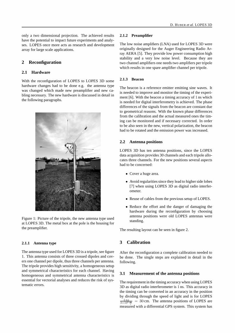
Figure 2: Scheme of the LOPES 3D antenna positionswithin the KASCADE [8] array. The LOPES 3D anten-nas are marked as stars, the KASCADE detector stationsas gray squares and the KASCADE-Grande detectors areshown as gray rectangles.
a resolution of≈ 1.5 cm in East and West and≈ 2 cm inthe height which is very well above the requirements.
3.2 Simulation of the antenna characteristics
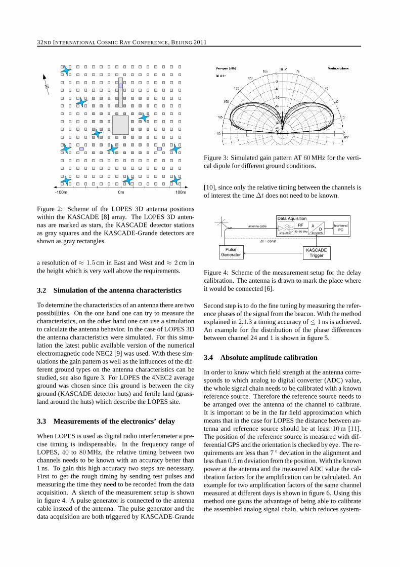
To determine the characteristics of an antenna there are twopossibilities. On the one hand one can try to measure thecharacteristics, on the other hand one can use a simulationto calculate the antenna behavior. In the case of LOPES 3Dthe antenna characteristics were simulated. For this simu-lation the latest public available version of the numericalelectromagnetic code NEC2 [9] was used. With these sim-ulations the gain pattern as well as the influences of the dif-ferent ground types on the antenna characteristics can bestudied, see also figure 3. For LOPES the 4NEC2 averageground was chosen since this ground is between the cityground (KASCADE detector huts) and fertile land (grass-land around the huts) which describe the LOPES site.
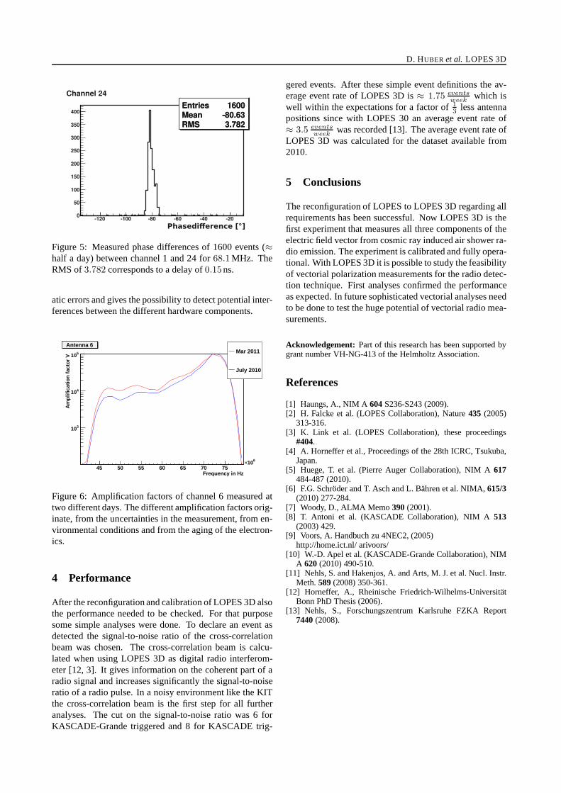
3.3 Measurements of the electronics’ delay
When LOPES is used as digital radio interferometer a pre-cise timing is indispensable. In the frequency range ofLOPES,40 to 80 MHz, the relative timing between twochannels needs to be known with an accuracy better than1 ns. To gain this high accuracy two steps are necessary.First to get the rough timing by sending test pulses andmeasuring the time they need to be recorded from the dataacquisition. A sketch of the measurement setup is shownin figure 4. A pulse generator is connected to the antennacable instead of the antenna. The pulse generator and thedata acquisition are both triggered by KASCADE-Grande
Figure 3: Simulated gain pattern AT60 MHz for the verti-cal dipole for different ground conditions.
[10], since only the relative timing between the channels isof interest the time∆t does not need to be known.
Figure 4: Scheme of the measurement setup for the delaycalibration. The antenna is drawn to mark the place whereit would be connected [6].
Second step is to do the fine tuning by measuring the refer-ence phases of the signal from the beacon. With the methodexplained in 2.1.3 a timing accuracy of≤ 1 ns is achieved.An example for the distribution of the phase differencesbetween channel 24 and 1 is shown in figure 5.
3.4 Absolute amplitude calibration
In order to know which field strength at the antenna corre-sponds to which analog to digital converter (ADC) value,the whole signal chain needs to be calibrated with a knownreference source. Therefore the reference source needs tobe arranged over the antenna of the channel to calibrate.It is important to be in the far field approximation whichmeans that in the case for LOPES the distance between an-tenna and reference source should be at least10 m [11].The position of the reference source is measured with dif-ferential GPS and the orientation is checked by eye. The re-quirements are less than7 ◦ deviation in the alignment andless than0.5 m deviation from the position. With the knownpower at the antenna and the measured ADC value the cal-ibration factors for the amplification can be calculated. Anexample for two amplification factors of the same channelmeasured at different days is shown in figure 6. Using thismethod one gains the advantage of being able to calibratethe assembled analog signal chain, which reduces system-
D. HUBER et al. LOPES 3D
Figure 5: Measured phase differences of 1600 events (≈
half a day) between channel 1 and 24 for68.1 MHz. TheRMS of3.782 corresponds to a delay of0.15ns.
atic errors and gives the possibility to detect potential inter-ferences between the different hardware components.
Frequency in Hz45 50 55 60 65 70 75
610×
Am
plif
icat
ion
fac
tor
V
310
410
510
Antenna 6Mar 2011
July 2010
Antenna 6
Figure 6: Amplification factors of channel 6 measured attwo different days. The different amplification factors orig-inate, from the uncertainties in the measurement, from en-vironmental conditions and from the aging of the electron-ics.
4 Performance
After the reconfiguration and calibration of LOPES 3D alsothe performance needed to be checked. For that purposesome simple analyses were done. To declare an event asdetected the signal-to-noise ratio of the cross-correlationbeam was chosen. The cross-correlation beam is calcu-lated when using LOPES 3D as digital radio interferom-eter [12, 3]. It gives information on the coherent part of aradio signal and increases significantly the signal-to-noiseratio of a radio pulse. In a noisy environment like the KITthe cross-correlation beam is the first step for all furtheranalyses. The cut on the signal-to-noise ratio was 6 forKASCADE-Grande triggered and 8 for KASCADE trig-
gered events. After these simple event definitions the av-erage event rate of LOPES 3D is≈ 1.75
eventsweek
which iswell within the expectations for a factor of1
3less antenna
positions since with LOPES 30 an average event rate of≈ 3.5
eventsweek
was recorded [13]. The average event rate ofLOPES 3D was calculated for the dataset available from2010.
5 Conclusions
The reconfiguration of LOPES to LOPES 3D regarding allrequirements has been successful. Now LOPES 3D is thefirst experiment that measures all three components of theelectric field vector from cosmic ray induced air shower ra-dio emission. The experiment is calibrated and fully opera-tional. With LOPES 3D it is possible to study the feasibilityof vectorial polarization measurements for the radio detec-tion technique. First analyses confirmed the performanceas expected. In future sophisticated vectorial analyses needto be done to test the huge potential of vectorial radio mea-surements.
Acknowledgement: Part of this research has been supported bygrant number VH-NG-413 of the Helmholtz Association.
References
[1] Haungs, A., NIM A604S236-S243 (2009).[2] H. Falcke et al. (LOPES Collaboration), Nature435 (2005)
313-316.[3] K. Link et al. (LOPES Collaboration), these proceedings
#404.[4] A. Horneffer et al., Proceedings of the 28th ICRC, Tsukuba,
Japan.[5] Huege, T. et al. (Pierre Auger Collaboration), NIM A617
484-487 (2010).[6] F.G. Schroder and T. Asch and L. Bahren et al. NIMA,615/3
(2010) 277-284.[7] Woody, D., ALMA Memo390(2001).[8] T. Antoni et al. (KASCADE Collaboration), NIM A513
(2003) 429.[9] Voors, A. Handbuch zu 4NEC2, (2005)
http://home.ict.nl/ arivoors/[10] W.-D. Apel et al. (KASCADE-Grande Collaboration), NIM
A 620(2010) 490-510.[11] Nehls, S. and Hakenjos, A. and Arts, M. J. et al. Nucl. Instr.
Meth.589(2008) 350-361.[12] Horneffer, A., Rheinische Friedrich-Wilhelms-Universitat
Bonn PhD Thesis (2006).[13] Nehls, S., Forschungszentrum Karlsruhe FZKA Report
7440(2008).