INSTALLATION · MANUAL 4 - wibre.de · Pour l‘intégration dans les bassins d‘eau de mer et de...
4
INSTALLATION · MANUAL 4.0299 Retrofit-Schwimmbad-Scheinwerfer, V4A-Edelstahl Retrofit-Swimmingpool-Light, V4A-stainless steel 316L Projecteur de Piscine – Version adaptable, acier inoxydable V4A WIBRE Elektrogeräte Edmund Breuninger GmbH & Co. KG · Liebigstrasse 9 · 74211 Leingarten/Germany Telefon: +49 (0) 7131 9053-0 · Telefax: +49 (0) 7131 9053-19 · E-Mail: [email protected] 1/4 1. Anwendung „Retrofit“- Unterwasser-Scheinwerfer zum nachträglichen Umrüsten bei bestehendem Beleuchtungsanlagen und montiertem Einbauge- häuse (WIBRE Serie 4.0268/4.0274) oder für Neuistallationen. Zzur Beleuchtung und Akzentuierung in Schwimmbädern, Whirl- pools oder Wasserspielen. Empfohlene Beckengröße (ca. 8 x 5 m) oder nach Absprache. Der Scheinwerfer ist für einen Einsatz bis 5,0 m Wassertiefe geeignet. Die Konstruktion ist komplett aus V4A-Edelstahl 1.4571 oder 1.4539 gefertigt und zusätzlich epoliert. Die Verwendung des Scheinwerfers 4.0299.00 in chloriertem Schwimmbadwasser ist möglich. Für den Einbau in Meerwasser- und Solebecken (bis 3,5% Solekonzentration) muss das Modell 4.0299.73 verwendet werden. Scheinwerfer ist vor Einfrieren zu schützen, das Wasser muss frei von Metall angreifenden Bestandteilen sein. Einbaugehäuse ist zur Installation erforderlich. Je nach Einbauart sind noch Druck- (4.0274.00.25), Klebe- (4.0274.55.55) oder Klebe und Druckflansch (4.0274.55.25) nötig. Zubehörteile (z.B. Betriebsgeräte) bitte separat bestellen. Achtung! Betrieb nur Unterwasser. Von jeglichen Kabelverbindungen im Einbaugehäuse bzw. im Kabelrohr wird abgeraten. Für die gesamte lichttechnische Anlage wird eine Überspannungs- schutzeinheit und die Verwendung eines Trenntrafos zur sicheren elektrischen Trennung (Schutztrennung) empfohlen. Sonderkonstruktionen-/anwendungen auf Anfrage. 2. Technische Daten/Konstruktion · Scheinwerfer komplett aus V4A-Edelstahl 1.4571 oder 1.4539, epoliert · Schutzart IP68 – Wassertiefe bis 5 m · runde Aufsatzblende aus V4A-Edelstahl, Blende 13 mm bei 4.0299.00 oder Blende 2 mm bei 4.0299.75 · mit 15 POW-LED 700 mA kaltweiss (6000 K), neutralweiss (4500 K), warmweiss (3000 K), royalblau · mit 9 Multichip RGB 700 mA · Konstantstromnetzteil/Trafo extern · rotationsymmetrische Lichtverteilung bei POW LED weiß und blau 90° und RGB 120° · Kabelverschraubung PG13,5, V4A Edelstahl, EPOL · Einbaugehäuse aus V4A-Edelstahl mit 1,5 m Kabelschutzrohr · Lieferung mit Leuchtmittel und 3 m Spezial-Unterwasserkabel 1. Application “Retrofit” underwater spotlights for retrofit modification of existing lighting systems and mounted installation housings (WIBRE series 4.0268/4.0274) or for new installations. For lighting and accentuation in swimming pools, whirlpools or fountains. Recommended basin size (approx. 8 x 5 m) or on consultation. The spotlight is suitable for use at a water depth of up to 5.0 m. It is made completely out of V4A stainless steel 1.4571 or 1.4539 and also electropolished. Spotlight 4.0299.00 can be used in chlorinated swimming pool water. For installation in seawater and salt water pools (up to 3.5% brine concentration), model 4.0299.73 must be used. The spotlight must be protected from freezing, and the water must be free of metal-corroding components. Installation housing is required for instal- lation. Depending on the type of installation, the pressure (4.0274.00.25), adhesive (4.0274.55.55) or adhesive-and-pressure flange (4.0274.55.25) is required. Please order accessory parts (e.g. control devices) separately. Note! Operation only underwater. Cable connections in the installation housing or conduit are not recom- mended. For the entire light system, an electrical surge protection unit and use of an insulating transformer for secure electrical disconnection (protective separation) are recommended. Special designs/applications on request. 2. Technical data/design · Spotlights made completely of V4A stainless steel 1.4571 or 1.4539 electropolished · Protection class IP68 – water depth up to 5 m · Round surface-mounted bezel made of V4A stainless steel, bezel 13 mm for 4.0299.00 or bezel 2 mm for 4.0299.75 · With 15 POW-LED 700 mA cold white (6000 K), neutral white (4500 K), warm white (3000 K), royal blue · with 9 multichip RGB 700 mA · Constant current power unit/external transformer · Rotation-symmetric light distribution with POW LED white and blue 90° and RGB 120° · Cable fitting PG13.5, V4A stainless steel, EPOL · Installation housing made of V4A stainless steel with 1.5 m cable conduit · Supplied with lamp and 3 m special underwater cable 1. Application Projecteur immergeable « Retrofit » pour l‘équipement ultérieur en cas d‘installations d‘éclairage existantes et de boîtier d‘encastrement monté (WIBRE série 4.0268/4.0274) ou pour les nouvelles installations. Pour l‘éclairage et la mise en valeur dans les piscines, les jacuzzis et les jeux d‘eau. Taille de bassin recommandée (env. 8 x 5 m) ou selon consultation. Le projecteur convient pour l‘utilisation jusqu‘à 5,0 m de profondeur d‘eau. La construction est complètement fabriquée en acier inoxydable V4A 1.4571 ou 1.4539 et électropolie. L‘utilisation du projecteur 4.0299.00 dans les piscines à eau chlorée est possible. Pour l‘intégration dans les bassins d‘eau de mer et de saumure (jusqu‘à une concentration de 3,5 %), il convient d‘utiliser le modèle 4.0299.73. Protéger le projecteur contre le gel, l‘eau doit être exempte de substances agressives pour les métaux. Le boîtier d‘encastrement est requis pour l‘installation. Selon le type d‘encastrement, il faut également utiliser une bride de pression (4.0274.00.25), une bride adhésive (4.0274.55.55) ou une bride adhésive et à pression (4.0274.55.25). Commander les accessoires (par ex. les équipements) séparément. Attention ! Fonctionnement uniquement sous l‘eau. Toutes les connexions de câbles dans le boîtier d‘encastrement ou la gaine de câbles sont déconseillées. Il est recommandé d‘utiliser, pour l‘ensemble de l‘installation technique d‘éclairage, une unité de surtension et un transformateur d‘isolement pour l‘isolation électrique sûre (isolation de protection). Constructions/applications spéciales sur demande. 2. Données techniques / construction · Projecteur entièrement en acier inoxydable V4A 1.4571 ou 1.4539, électropoli · Classe de protection IP68 – Profondeur jusqu‘à 5 m · Garniture ronde en acier inoxydable V4A, garniture de 13 mm pour 4.0299.00 ou de 2 mm pour 4.0299.75 · avec 15 POW-LED 700 mA blanc froid (6000 K), blanc neutre (4500 K), blanc chaud (3000 K), bleu roi avec 9 Multichip RVB 700 mA · Bloc d‘alimentation en courant continu / transformateur externe · Répartition de la lumière par symétrie de rotation pour POW LED blanc et bleu 90° et RVB 120° · Raccord de câble PG13,5, acier inoxydable V4A, EPOL · Boîtier d‘encastrement en acier inoxydable V4A, avec gaine de 1,5 m · Livraison avec dispositif d‘éclairage et câble subaquatique spécial de 3 m IP 68 3 M V4A EDELSTAHL KABEL INKL INKL EDELSTAHL WK-Nr. 1.4539 13 47 258 161 120 120 2 58 238 161 120 120 180 45° 95 226 95 183 183 4.0299 4.0299.75 4.0299 4.0299 + 4.1367 4.0299.50.00 4.0299.00.00 4.0299.00 4.0299.75
Transcript of INSTALLATION · MANUAL 4 - wibre.de · Pour l‘intégration dans les bassins d‘eau de mer et de...

INSTALLATION · MANUAL
4.0299Retrofit-Schwimmbad-Scheinwerfer, V4A-Edelstahl Retrofit-Swimmingpool-Light, V4A-stainless steel 316LProjecteur de Piscine – Version adaptable, acier inoxydable V4A
WIBRE Elektrogeräte Edmund Breuninger GmbH & Co. KG · Liebigstrasse 9 · 74211 Leingarten/GermanyTelefon: +49 (0) 7131 9053-0 · Telefax: +49 (0) 7131 9053-19 · E-Mail: [email protected] 1/4
1. Anwendung„Retrofit“- Unterwasser-Scheinwerfer zum nachträglichen Umrüsten bei bestehendem Beleuchtungsanlagen und montiertem Einbauge-häuse (WIBRE Serie 4.0268/4.0274) oder für Neuistallationen.Zzur Beleuchtung und Akzentuierung in Schwimmbädern, Whirl-pools oder Wasserspielen. Empfohlene Beckengröße (ca. 8 x 5 m) oder nach Absprache.Der Scheinwerfer ist für einen Einsatz bis 5,0 m Wassertiefe geeignet. Die Konstruktion ist komplett aus V4A-Edelstahl 1.4571 oder 1.4539 gefertigt und zusätzlich epoliert. Die Verwendung des Scheinwerfers 4.0299.00 in chloriertem Schwimmbadwasser ist möglich. Für den Einbau in Meerwasser- und Solebecken (bis 3,5% Solekonzentration) muss das Modell 4.0299.73 verwendet werden.Scheinwerfer ist vor Einfrieren zu schützen, das Wasser muss frei von Metall angreifenden Bestandteilen sein. Einbaugehäuse ist zur Installation erforderlich. Je nach Einbauart sind noch Druck- (4.0274.00.25), Klebe- (4.0274.55.55) oder Klebe und Druckflansch (4.0274.55.25) nötig.Zubehörteile (z.B. Betriebsgeräte) bitte separat bestellen.Achtung! Betrieb nur Unterwasser. Von jeglichen Kabelverbindungen im Einbaugehäuse bzw. im Kabelrohr wird abgeraten.Für die gesamte lichttechnische Anlage wird eine Überspannungs-schutzeinheit und die Verwendung eines Trenntrafos zur sicheren elektrischen Trennung (Schutztrennung) empfohlen.Sonderkonstruktionen-/anwendungen auf Anfrage.
2. Technische Daten/Konstruktion· Scheinwerfer komplett aus V4A-Edelstahl 1.4571 oder 1.4539, epoliert· Schutzart IP68 – Wassertiefe bis 5 m· runde Aufsatzblende aus V4A-Edelstahl,
Blende 13 mm bei 4.0299.00 oder Blende 2 mm bei 4.0299.75· mit 15 POW-LED 700 mA kaltweiss (6000 K), neutralweiss (4500 K),
warmweiss (3000 K), royalblau· mit 9 Multichip RGB 700 mA · Konstantstromnetzteil/Trafo extern· rotationsymmetrische Lichtverteilung bei
POW LED weiß und blau 90° und RGB 120°· Kabelverschraubung PG13,5, V4A Edelstahl, EPOL· Einbaugehäuse aus V4A-Edelstahl mit 1,5 m Kabelschutzrohr· Lieferung mit Leuchtmittel und 3 m Spezial-Unterwasserkabel
1. Application“Retrofit” underwater spotlights for retrofit modification of existing lighting systems and mounted installation housings (WIBRE series 4.0268/4.0274) or for new installations.For lighting and accentuation in swimming pools, whirlpools or fountains. Recommended basin size (approx. 8 x 5 m) or on consultation.The spotlight is suitable for use at a water depth of up to 5.0 m. It is made completely out of V4A stainless steel 1.4571 or 1.4539 and also electropolished. Spotlight 4.0299.00 can be used in chlorinated swimming pool water. For installation in seawater and salt water pools (up to 3.5% brine concentration), model 4.0299.73 must be used.The spotlight must be protected from freezing, and the water must be free of metal-corroding components. Installation housing is required for instal-lation. Depending on the type of installation, the pressure (4.0274.00.25), adhesive (4.0274.55.55) or adhesive-and-pressure flange (4.0274.55.25) is required.Please order accessory parts (e.g. control devices) separately.Note! Operation only underwater. Cable connections in the installation housing or conduit are not recom-mended.For the entire light system, an electrical surge protection unit and use of an insulating transformer for secure electrical disconnection (protective separation) are recommended.Special designs/applications on request.
2. Technical data/design· Spotlights made completely of V4A stainless steel 1.4571 or 1.4539
electropolished· Protection class IP68 – water depth up to 5 m· Round surface-mounted bezel made of V4A stainless steel,
bezel 13 mm for 4.0299.00 or bezel 2 mm for 4.0299.75· With 15 POW-LED 700 mA cold white (6000 K), neutral white (4500 K), warm white (3000 K), royal blue
· with 9 multichip RGB 700 mA · Constant current power unit/external transformer· Rotation-symmetric light distribution with
POW LED white and blue 90° and RGB 120°· Cable fitting PG13.5, V4A stainless steel, EPOL· Installation housing made of V4A stainless steel with 1.5 m cable conduit· Supplied with lamp and 3 m special underwater cable
1. ApplicationProjecteur immergeable « Retrofit » pour l‘équipement ultérieur en cas d‘installations d‘éclairage existantes et de boîtier d‘encastrement monté (WIBRE série 4.0268/4.0274) ou pour les nouvelles installations.Pour l‘éclairage et la mise en valeur dans les piscines, les jacuzzis et les jeux d‘eau. Taille de bassin recommandée (env. 8 x 5 m) ou selon consultation.Le projecteur convient pour l‘utilisation jusqu‘à 5,0 m de profondeur d‘eau. La construction est complètement fabriquée en acier inoxydable V4A 1.4571 ou 1.4539 et électropolie. L‘utilisation du projecteur 4.0299.00 dans les piscines à eau chlorée est possible. Pour l‘intégration dans les bassins d‘eau de mer et de saumure (jusqu‘à une concentration de 3,5 %), il convient d‘utiliser le modèle 4.0299.73.Protéger le projecteur contre le gel, l‘eau doit être exempte de substances agressives pour les métaux. Le boîtier d‘encastrement est requis pour l‘installation. Selon le type d‘encastrement, il faut également utiliser une bride de pression (4.0274.00.25), une bride adhésive (4.0274.55.55) ou une bride adhésive et à pression (4.0274.55.25).Commander les accessoires (par ex. les équipements) séparément.Attention ! Fonctionnement uniquement sous l‘eau. Toutes les connexions de câbles dans le boîtier d‘encastrement ou la gaine de câbles sont déconseillées.Il est recommandé d‘utiliser, pour l‘ensemble de l‘installation technique d‘éclairage, une unité de surtension et un transformateur d‘isolement pour l‘isolation électrique sûre (isolation de protection).Constructions/applications spéciales sur demande.
2. Données techniques / construction· Projecteur entièrement en acier inoxydable V4A 1.4571 ou 1.4539,
électropoli· Classe de protection IP68 – Profondeur jusqu‘à 5 m· Garniture ronde en acier inoxydable V4A, garniture de 13 mm pour
4.0299.00 ou de 2 mm pour 4.0299.75· avec 15 POW-LED 700 mA blanc froid (6000 K), blanc neutre (4500 K),
blanc chaud (3000 K), bleu roi avec 9 Multichip RVB 700 mA· Bloc d‘alimentation en courant continu / transformateur externe· Répartition de la lumière par symétrie de rotation pour POW LED blanc et
bleu 90° et RVB 120°· Raccord de câble PG13,5, acier inoxydable V4A, EPOL· Boîtier d‘encastrement en acier inoxydable V4A, avec gaine de 1,5 m· Livraison avec dispositif d‘éclairage et câble subaquatique spécial de 3 m
IP68 3 M V4AEDELSTAHL
KABELINKLINKL
EDELSTAHLWK-Nr.
1.4539
13
47
258 161120
120
2
58
238 161120
120 180
45°
95
226
95
183 183
4.0299 4.0299.75 4.0299 4.0299 + 4.1367
4.0299.50.004.0299.00.004.0299.00 4.0299.75

INSTALLATION · MANUAL
2/4 WIBRE Elektrogeräte Edmund Breuninger GmbH & Co. KG · Liebigstrasse 9 · 74211 Leingarten/GermanyTelefon: +49 (0) 7131 9053-0 · Telefax: +49 (0) 7131 9053-19 · E-Mail: [email protected]
3. Installation des Einbaugehäuse (4.0299.00.00) bei einer Neuinstallation und Montage der Befestigungselemente
ACHTUNG: Bei einer Installation in vorhandene Einbaugehäuse (4.0274) bitte Hinweise ab Punkt 4 beachten! Zur Installation sind die nationalen Sicherheitsvorschriften zu beachten. Es wird keine Haftung für unsach gemäßen Einsatz oder Montage übernommen. Bei nachträglichen Änderungen an den Leuchten wird keine Haftung übernommen.
3.1 Einbau in Betonbecken (Eingießen in Beton) mit Fliesen-auskleidungDie Schutzfolie auf dem Einbautopf nicht beschädigen und erst bei Installation der Innenteile entfernen! Kon takt mit Baustahl ist zu vermeiden! Das Einbaugehäuse einmessen (Teilkreis 204 mm) und laut em pfoh lener Einbautiefe mit den zwei beiliegenden Kunststoffschrauben M6x60 so an der Verschalung befes ti gen, dass die Leitungsverschraubung 45° seitlich versetzt ist und die Gewindebuchsen horizontal/vertikal aus gerichtet sind. (siehe 3.1) Kabelschutzschlauch am Einbautopf anschellen und möglichst über den Was serspiegel und in großem Radius verlegen. Nach Entfernen der Verschalung bis an den Innenrand des Ein bautopfes anfliesen, Schutzfolie entfernen. 3.2 Einbau in Betonbecken mit Folienauskleidung (feste Folie) mittels DruckflanschDer Einbau des Einbautopfes entspricht dem Einbau in Betonbecken. Die auf dem Einbautopf aufgebrachte Schutzfolie vor Einlegen der Beckenfolie entfernen!Nachdem die Beckenfolie eingelegt ist, werden die erforderlichen Öffnungen für Schein werfer (ø182 mm) und den Lochungen (ø7 mm) für die V4A-Schrauben M6x30 ausgeschnitten. Der Edelstahl-druckflansch (4.0274.00.25) kann hier als Schablone verwendet wer-den. Der Edelstahldruckflansch wird mit den Schrauben V4A M6x30, Flachdichtung, Beckenfolie, Flachdichtung (Reihen folge beachten) in den Gewindebuchsen am Einbau topf fest verschraubt.Achtung: Flachdichtungen laut Grafik verwenden, die Becken-folie muss unbedingt zwischen den beiden Flachdichtungen des Edelstahldruckflansches (4.0274.00.25) liegen.
14 mm
3.6
Mörtel/mortar
Fliesen/tiles
Kunststoffwinkelring/plastic adapter ring
Scheinwerfer/spotlight
V4A-Schraube M6x10/ V4A-screw M6x10Kunststoffbefestigungsring/plastic fastening ring
V4A-Schraube M6x20/ V4A-screw M6x20
Dichtung/seal
3.01
3
4652
1. Scheinwerfer/spotlight 4.02992. Einbautopf/installation housing 4.0299.00.003. 2x Schraube/screw M6x40 oder/or M6x80 V4A4. Kabelverschraubung komplett/cable gland complete PG13,55. Befestigungsbügel Edelstahl/fastening ring steel (9.0299.00.10)6. Spezial-Unterwasserkabel/special underwater cable
3.1
Betonwand/concrete wall
Mörtel/mortar
Fliesen/tiles
Scheinwerfer/spotlight
3.2
Flachdichtung/ flat seal
Flachdichtung/flat seal
Beckenfolie/pool liner foil
Edelstahl-Druckflansch/stainless steel pressure flange
V4A-Schraube M6x30V4A-screw M6x30
Kunststoffformscheibe/plastic shaped washer
Scheinwerfer/spotlight
3.3
Kunststoffformscheibe/plastic shaped washer
Edelstahl-Druckflansch/stainless steel pressure flange
Flachdichtung/flat seal
Flachdichtung/flat seal
Beckenwand/pool wall
V4A-Schraube M6x30V4A-screw M6x30
Scheinwerfer/spotlight
3.4
dichtgeschweißtIP68/welded IP68
V4A-Blech/V4A-wall
Scheinwerfer/spotlight
3.5
Klebefolie/adhesive foil
Klebeflansch/adhesive flange
Flachdichtung/flat seal
Scheinwerfer/spotlight
Fliesenaufbau optimal 14 mm!/Tile+mortar optimum 14 mm!
3. Installation of the installation housing (4.0299.00.00) in a new installation and mounting of the fastening elements
NOTE: When installing in an existing installation housing (4.0274), please follow the instructions from point 4! National safety regulations must be followed during installation. No liability will be accepted for improper use or mounting. No liability will be accepted in case of subsequent changes to the lights.
3.1 Installation in concrete basins (in poured concrete) with tile coveringDo not damage the protective foil on the built-in housing and remove it only when installing the internal parts! Avoid contact with structural steel! Measure the installation housing (arc 204 mm) and fasten it to the shea-thing at the recommended installation depth with the two accompanying M6x60 plastic screws so that the line fitting is laterally offset 45° and the threaded bushings are oriented horizontally/vertically. (see 3.1) Clamp cable conduit to the built-in housing and emplace it, if possible, above the water surface and in a large radius. After removing the sheathing, tile up to the inside edge of the built-in housing and remove protective foil. 3.2 Installation in concrete basin with foil lining (firm foil) using pressure flangesInstallation of the built-in housing corresponds to installation in concrete basins. Remove the protective foil attached to the built-in housing before emplacing the basin foil!After the basin foil is installed, the required openings for spotlights (ø182 mm) and the holes (ø7 mm) for the V4A screws M6x30 are cut out. The stainless steel pressure flange (4.0274.00.25) can be used as a pattern here. The stainless steel pressure flange is firmly screwed into the built-in housing with screws V4A M6x30, gasket, basin foil and gasket (observe sequence) in the threaded bushings.Note: Use gaskets in accordance with the figure; the basin foil must always lie between the two gaskets of the stainless steel pressure flange (4.0274.00.25).
3. Installation d‘un boîtier d‘encastrement (4.0299.00.00) en cas de nouvelle installation et montage des éléments de fixation
ATTENTION : en cas d‘installation dans un boîtier d‘encastrement (4.0274) existant, respecter les instructions à partir du point 4 ! Respecter les prescriptions de sécurité nationales pour l‘installation. Toute responsabilité pour l‘utilisation et le montage incorrect est déclinée. Toute responsabilité est déclinée pour les modifications ultérieures sur les lampes.
3.1 Intégration dans des dalles en béton (scellement) à revête-ment de carrelageNe pas endommager le film de protection sur le boîtier d‘encastrement et ne l‘enlever que lors de l‘installation des éléments intérieurs ! Éviter tout contact avec l‘acier de construction ! Mesurer le boîtier d‘encastrement (section circulaire de 204 mm) et le fixer au coffrage conformément à la profondeur de montage recommandée avec deux vis pour plastique M6x60 de manière à ce que le raccord à vis du câblage soit décalé de 45° sur le côté et que les douilles filetées sont alignées à l‘horizontale/la verticale. (voir 3.1) Fixer la gaine de protection des câbles au boîtier d‘encastrement à l‘aide d‘un collier et la poser, si possible, au-dessus du niveau d‘eau et en respectant un grand rayon. Après avoir retiré le coffrage, carreler jusqu‘au bord intérieur du boîtier d‘encastrement et retirer le film de protection. 3.2 Intégration dans les dalles en béton avec habillage de film (film fixe) au moyen d‘un bride de pressionL‘intégration du boîtier d‘encastrement est identique à l‘intégration dans des dalles en béton. Retirer le film de protection appliqué sur le boîtier d‘encastrement avant la mise en place du liner du bassin.Après avoir posé le liner du bassin, découper les ouvertures requises pour le projecteur (ø182 mm) et les trous (ø7 mm) pour les vis V4A M6x30. La bride de pression en acier inoxydable (4.0274.00.25) peut être utilisée comme gabarit. Visser fermement la bride de pression en acier inoxydable avec les vis V4A M6x30, les joints plats, le liner de bassin, le joint plat (respecter l‘ordre) dans les douilles filetées du boîtier d‘encastrement.Attention: utiliser les joints plats conformément à l‘illustration, le liner de bassin doit impérativement être placé entre les deux joints plats de la bride de pression en acier inoxydable (4.0274.00.25).
INSTALLATION · MANUAL
WIBRE Elektrogeräte Edmund Breuninger GmbH & Co. KG · Liebigstrasse 9 · 74211 Leingarten/GermanyTelefon: +49 (0) 7131 9053-0 · Telefax: +49 (0) 7131 9053-19 · E-Mail: [email protected] 3/4
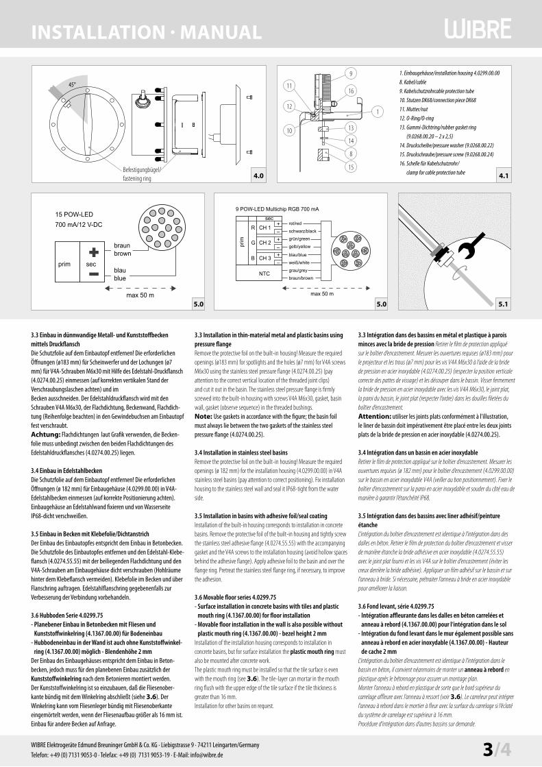
3.3 Einbau in dünnwandige Metall- und Kunststoffbecken mittels DruckflanschDie Schutzfolie auf dem Einbautopf entfernen! Die erforderlichen Öffnungen (ø183 mm) für Scheinwerfer und der Lochungen (ø7 mm) für V4A-Schrauben M6x30 mit Hilfe des Edelstahl-Druckflansch (4.0274.00.25) einmessen (auf korrekten vertikalen Stand der Verschraubungslaschen achten) und im Becken ausschneiden. Der Edelstahldruckflansch wird mit den Schrauben V4A M6x30, der Flachdichtung, Beckenwand, Flachdich-tung (Reih en folge beachten) in den Gewindebuchsen am Einbautopf fest verschraubt.Achtung: Flachdichtungen laut Grafik verwenden, die Becken-folie muss unbedingt zwischen den beiden Flachdichtungen des Edelstahldruckflansches (4.0274.00.25) liegen.
3.4 Einbau in EdelstahlbeckenDie Schutzfolie auf dem Einbautopf entfernen! Die erforderlichen Öffnungen (ø 182 mm) für Einbaugehäuse (4.0299.00.00) in V4A-Edelstahlbecken einmessen (auf korrekte Positionie rung achten). Einbaugehäuse an Edelstahlwand fixieren und von Wasserseite IP68-dicht verschweißen. 3.5 Einbau in Becken mit Klebefolie/DichtanstrichDer Einbau des Einbautopfes entspricht dem Einbau in Betonbecken. Die Schutzfolie des Einbautopfes entfernen und den Edelstahl-Klebe-flansch (4.0274.55.55) mit der beiliegenden Flachdichtung und den V4A-Schrauben am Einbaugehäuse dicht verschrauben (Hohlräume hinter dem Klebeflansch vermeiden). Klebefolie im Becken und über Flanschring auftragen. Edelstahlflanschring gegebenenfalls zur Verbesserung der Verbindung vorbehandeln. 3.6 Hubboden Serie 4.0299.75 - Planebener Einbau in Betonbecken mit Fliesen und
Kunststoffwinkelring (4.1367.00.00) für Bodeneinbau- Hubbodeneinbau in der Wand ist auch ohne Kunststoffwinkel-
ring (4.1367.00.00) möglich - Blendenhöhe 2 mmDer Einbau des Einbaugehäuses entspricht dem Einbau in Beton-becken, jedoch muss für den planebenen Einbau zusätzlich der Kunststoffwinkelring nach dem Betonieren montiert werden.Der Kunststoffwinkelring ist so einzubauen, daß die Fliesenober-kante bündig mit dem Winkelring abschließt (siehe 3.6). Der Winkelring kann vom Fliesenleger bündig mit Fliesenoberkante eingemörtelt werden, wenn der Fliesenaufbau größer als 16 mm ist.Einbau für andere Becken auf Anfrage.
4.1
1
13
14
8
15
10
12
1116
9 1. Einbaugehäuse/installation housing 4.0299.00.00
8. Kabel/cable
9. Kabelschutzrohrcable protection tube
10. Stutzen DK68/connection piece DK68
11. Mutter/nut
12. O-Ring/O-ring
13. Gummi-Dichtring/rubber gasket ring
(9.0268.00.20 – 2 x 2,5)
14. Druckscheibe/pressure washer (9.0268.00.22)
15. Druckschraube/pressure screw (9.0268.00.24)
16. Schelle für Kabelschutzrohr/
clamp for cable protection tube
45°
4.0Befestigungbügel/fastening ring
max 50 m
secprim
15 POW-LED 700 mA/12 V-DC
braunbrown
blaublue
max 50 m
9 POW-LED Multichip RGB 700 mA
braun/brown
rot/red
blau/blue
schwarz/black
grün/green
gelb/yellow
grau/grey
weiß/white
sec
prim
CH 1
CH 2
CH 3
NTC
R
G
B
+–+–+–
5.15.0 5.0
3.3 Installation in thin-material metal and plastic basins using pressure flangeRemove the protective foil on the built-in housing! Measure the required openings (ø183 mm) for spotlights and the holes (ø7 mm) for V4A screws M6x30 using the stainless steel pressure flange (4.0274.00.25) (pay attention to the correct vertical location of the threaded joint clips) and cut it out in the basin. The stainless steel pressure flange is firmly screwed into the built-in housing with screws V4A M6x30, gasket, basin wall, gasket (observe sequence) in the threaded bushings.Note: Use gaskets in accordance with the figure; the basin foil must always lie between the two gaskets of the stainless steel pressure flange (4.0274.00.25).
3.4 Installation in stainless steel basinsRemove the protective foil on the built-in housing! Measure the required openings (ø 182 mm) for the installation housing (4.0299.00.00) in V4A stainless steel basins (pay attention to correct positioning). Fix installation housing to the stainless steel wall and seal it IP68-tight from the water side. 3.5 Installation in basins with adhesive foil/seal coatingInstallation of the built-in housing corresponds to installation in concrete basins. Remove the protective foil of the built-in housing and tightly screw the stainless steel adhesive flange (4.0274.55.55) with the accompanying gasket and the V4A screws to the installation housing (avoid hollow spaces behind the adhesive flange). Apply adhesive foil to the basin and over the flange ring. Pretreat the stainless steel flange ring, if necessary, to improve the adhesion.
3.6 Movable floor series 4.0299.75 - Surface installation in concrete basins with tiles and plastic
mouth ring (4.1367.00.00) for floor installation- Movable floor installation in the wall is also possible without
plastic mouth ring (4.1367.00.00) - bezel height 2 mmInstallation of the installation housing corresponds to installation in concrete basins, but for surface installation the plastic mouth ring must also be mounted after concrete work.The plastic mouth ring must be installed so that the tile surface is even with the mouth ring (see 3.6). The tile-layer can mortar in the mouth ring flush with the upper edge of the tile surface if the tile thickness is greater than 16 mm.Installation for other basins on request.
3.3 Intégration dans des bassins en métal et plastique à parois minces avec la bride de pression Retirer le film de protection appliqué sur le boîtier d‘encastrement. Mesurer les ouvertures requises (ø183 mm) pour le projecteur et les trous (ø7 mm) pour les vis V4A M6x30 à l‘aide de la bride de pression en acier inoxydable (4.0274.00.25) (respecter la position verticale correcte des pattes de vissage) et les découper dans le bassin. Visser fermement la bride de pression en acier inoxydable avec les vis V4A M6x30, le joint plat, la paroi du bassin, le joint plat (respecter l‘ordre) dans les douilles filetées du boîtier d‘encastrement.Attention: utiliser les joints plats conformément à l‘illustration, le liner de bassin doit impérativement être placé entre les deux joints plats de la bride de pression en acier inoxydable (4.0274.00.25).
3.4 Intégration dans un bassin en acier inoxydableRetirer le film de protection appliqué sur le boîtier d‘encastrement. Mesurer les ouvertures requises (ø 182 mm) pour le boîtier d‘encastrement (4.0299.00.00) sur le bassin en acier inoxydable V4A (veiller au bon positionnement). Fixer le boîtier d‘encastrement sur la paroi en acier inoxydable et souder du côté eau de manière à garantir l‘étanchéité IP68. 3.5 Intégration dans des bassins avec liner adhésif/peinture étancheL‘intégration du boîtier d‘encastrement est identique à l‘intégration dans des dalles en béton. Retirer le film de protection du boîtier d‘encastrement et visser de manière étanche la bride adhésive en acier inoxydable (4.0274.55.55) avec le joint plat fourni et les vis V4A sur le boîtier d‘encastrement (éviter les creux derrière la bride adhésive). Appliquer un film adhésif sur le bassin et sur l‘anneau à bride. Si nécessaire, prétraiter l‘anneau à bride en acier inoxydable pour améliorer la liaison. 3.6 Fond levant, série 4.0299.75 - Intégration affleurante dans les dalles en béton carrelées et
anneau à rebord (4.1367.00.00) pour l‘intégration dans le sol- Intégration du fond levant dans le mur également possible sans
anneau à rebord en acier inoxydable (4.1367.00.00) - Hauteur de cache 2 mm
L‘intégration du boîtier d‘encastrement est identique à l‘intégration dans le bassin en béton, il convient néanmoins de monter un anneau à rebord en plastique après le bétonnage pour assurer un montage plan.Monter l‘anneau à rebord en plastique de sorte que le bord supérieur du carrelage affleure avec l‘anneau à ressort (voir 3.6). Le carreleur peut intégrer l‘anneau à rebord dans le mortier à fleur avec la surface du carrelage si l‘éclaté du système de carrelage est supérieur à 16 mm.Procédure d‘intégration dans d‘autres bassins sur demande.

INSTALLATION · MANUAL
4/4 WIBRE Elektrogeräte Edmund Breuninger GmbH & Co. KG · Liebigstrasse 9 · 74211 Leingarten/GermanyTelefon: +49 (0) 7131 9053-0 · Telefax: +49 (0) 7131 9053-19 · E-Mail: [email protected]
W37
5 St
and 0
04.1
6 - T
echn
ische
Änd
erun
gen
vorb
ehal
ten
- Für
Dru
ckfeh
ler ü
bern
ehm
en w
ir ke
ine H
aftu
ng
4. Montage des ScheinwerfersDas Silikonkabel durch die innenliegende Kabelverschraubung des Einbaugehäuses in das Kabelschutzrohr einführen und ca 1,2 m Kabel im Einbaugehäuse einwickeln. Die Kabelverschraubung DK68 Stutzen festziehen, damit das Kabel abgedichtet wird 5.1. Den Scheinwerfer einsetzen, ausrichten und festschrauben.
Hinweis: Bei der Installation in ein vorhandes Einbaugehäuse (4.0274) muss der vorhandene Einbaubügel entfernt werden und ein neuer Einbaubügel (9.0299.00.10 oder 9.0299.73.10) eingesetzt werden. Das eventuell vorhandene Kabel ebenfalls entfernt werden.
Achtung: Nur werkseitig angeschlossenes Kabel verwenden. Gewünschte Kabellänge bei Bestellung angeben.Einzelanschlussader entsprechend den Vorschriften an den Netztei-len elektrisch anschließen 5.0. Die maximale Anzahl von Leuchten und Anschlußart siehe auch Manual des entsprechenden Netzteiles.
5. Wartung und LeuchtmittelwechselScheinwerfer spannungsfrei schalten und Gehäuse öffnen. Leucht-mittel durch identisches austauschen und Gehäuse laut Vorschrift wieder verschließen.Hierbei Dichtungen zwischen Glas und Gehäuse und der Kabelver-schraubung auf Abnutzung oder Beschädigung überprüfen und gegebenenfalls wechseln. Verunreinigungen und Ablagerungen auf Glas oder Edelstahlteilen sind mit handelsüblichen Reinigungsmit-teln zu entfernen.
6. Allgemeine Wartungshinweise· Beim Reinigen darf die Leuchte nicht mit Metall angreifenden Reinigungs-
mitteln in Berührung kommen. Der Einsatz salzsäurehaltiger Reinigungs-mittel an und in der Nähe von Scheinwerferteilen aus Edelstahl ist in jedem Fall zu unterlassen.
· Scheinwerfer und Einbaugehäuse regelmäßig reinigen, um Fremdrostabla-gerungen zu vermeiden.
· Achtung: Keine Hochdruckreiniger verwenden.· Strahler vor Einfrieren schützen, gegebenenfalls müssen diese demontiert oder
speziell geschützt werden.· Verloren gegangene Schrauben dürfen nur durch Schrauben aus V4A ersetzt
werden.· Je nach Beanspruchung (Höhe der Watttage) und Wasserqualität ist alle 5–8
Jahre ein Wechsel der Dichtungen (Glasscheibe, Verschraubung, O-Ring) und der Kabel zu empfehlen.
7. GarantiebestimmungenFolgende Garantiezeiten und Bestimmungen gelten vom Tage der Lieferung an:· 24 Monate auf WIBRE-Scheinwerfer.· Von den Garantieansprüchen ausgenommen sind Leuchtmittel· Unter die Garantie fallen nachweisbare Material-, Konstruktions- und
Verarbeitungsfehler vonseiten des Herstellers.· Für Schäden, welche durch Nichtbeachtung dieser Betriebsanleitung, oder
durch unsachgemäße Reparatur entstehen, können wir keine Garantie übernehmen.
· Keine Garantie besteht, wenn die Installation nicht korrekt nach den Bestimmungen vorgenommen wurde oder bei Verwendung nicht geeigneter Leuchtmittel bzw. Anschlusskabel.
· Änderungen, die dem technischen Fortschritt dienen, behalten wir uns vor.
8. Wichtige Hinweise(Bei Nichtbeachtung entfällt die Garantie.)• Vor der Installation müssen alle Teile auf Transportschäden überprüft werden!• Jegliche Montage-, Installations- und Elektroarbeiten müssen von
qualifiziertem Fachpersonal durchgeführt werden.• Zur Vermeidung von Fremdrost nur Edelstahlwerkzeug verwenden!• Die Kabellänge der Leuchten ist so zu wählen, dass man nicht im Wasser oder
feuchten Umgebung verlängern muss. Spätere Reklamationen aufgrund dessen können nicht akzeptiert werden.
• Es dürfen nur originale Wibre-Betriebsgeräte verwendet werden.• Ein Montageabstand von 10 cm zwischen Betriebsgeräten wird dringend
empfohlen, um wechselseitiges Erhitzen zu vermeiden.• Anschluss der Betriebsgeräte muss stromlos erfolgen, da sonst Entladungen
im Netzteil zur Schädigung der LED führen können. Es darf keine Primärspannung beim Wechsel der LED anliegen.
• Beim Anschließen der Leuchte die Polung beachten! Eine falsche Polung kann dem LED-Modul schaden.
• Die Installation eines bauseitigen Überspannungsschutzes nach DIN VDE 0100-443, DIN VDE 0100-534 und EN 62305 wird empfohlen.
• Bitte achten Sie auf Maßnahmen gegen ESD (Elektrostatische Entladung) während aller Arbeiten am Scheinwerfer, Betriebsgerät und LED.
4. Mounting of the spotlightGuide the silicone cable through the inside cable fitting of the installation housing into the cable conduit and coil approx. 1.2 m of cable in the installation housing. Tighten the cable fitting DK68 socket so that the cable is sealed 5.1. Insert, align and tighten the spotlight.
Note: When installing in an existing installation housing (4.0274), the existing installation bracket must be removed and a new instal-lation bracket (9.0299.00.10 or 9.0299.73.10) installed. The cable, if present, must also be removed.
Note: Use only the factory-connected cable. Specify the desired cable length when ordering.Electrically connect individual connection wires to the power units in accordance with regulations 5.0. Also see the manual of the corresponding power unit for the maximum number of lamps and connection type.
5. Maintenance and replacement of lampsSwitch off power to the spotlights and open the housing. Replace lamp with an identical one and seal the housing again in accordance with the regulation.In doing so, check seals between glass and housing and the cable fitting for wear or damage and replace, if necessary. Remove dirt and deposits on the glass or stainless steel parts with commercially available cleaning agents.We introduce ourselves.
6. General Maintenance Indications· When cleaning, make sure that the lights do not come into contact with metal-corroding cleaning agents. The use of acid-containing cleaning agents on or near stainless-steel spotlight parts must always be avoided.
· Clean spotlights and installation housing regularly to avoid extraneous rust deposits. · Attention: Do not use high-pressure cleaners.· Protect lightbulbs from freezing; they must be removed, if necessary, or specially
protected.· Lost screws may only be replaced by screws made of V4A.· Depending on load (wattage) and water quality, we recommend changing the seals
(on the glass pane, fitting, O-ring) and cable every 5–8 years.
7. Warranty ConditionsThe following warranty periods and conditions apply from the day of delivery:· 24 months on WIBRE spotlights.· Lamps and LED units are excluded from warranty claims.· The warranty covers verifiable material, design and work errors by the manufacturer.
· We cannot accept liability for damages caused by failure to comply with this operating manual or through improper repair.
· The warranty is void if the installation was not performed properly according to the instructions or unsuitable lamps or connecting cables are used.
· We reserve the right to make changes for the purpose of technical progress.
8. Important information(If the following points are disregarded, the guarantee expires.)• Before installation, all parts must be checked for transport damage!• All fitting, installation and electrical work must be performed
by qualified specialist staff.• Only use stainless steel tools to avoid external rust!• The cable length of the lights should be chosen in such a way that it is not necessary
to extend in water or moist environments. Later complaints resulting from this cannot be accepted.
• Only original Wibre operating units may be used.• An installation distance of 10 cm between operating devices is urgently
recommended in order to avoid mutual heating up.• The operating devices must be connected without power, as otherwise discharges
in the power supply may cause the LED to be damaged. No primary voltage may be applied when changing the LED.
• Note polarity when changing the lights! The wrong polarity can damage the LED module.
• It is recommended that the customer install an overvoltage protection in accordance with DIN VDE 0100-443, DIN VDE 0100-534 and EN 62305.
• Please comply with all anti-ESD (electrostatic discharge) measures during all work on the spotlight, operating device and LED.
4. Montage du projecteurIntroduire le câble en silicone dans le raccord de câble intérieur du boîtier d‘encastrement dans la gaine de protection des câbles et enrouler env. 1,2 m de câble dans le boîtier d‘encastrement. Fixer les appuis du raccord de câble DK68 pour que le câble soit étanchéifié 5.1. Insérer le projecteur, l‘aligner et le visser.
Remarque : lors de l‘installation dans un boîtier d‘encastrement existant (4.0274), retirer l‘étrier de montage et le remplacer par un nouvel étrier de montage (9.0299.00.10 ou 9.0299.73.10). Le câble, s‘il y en a un, doit également être retiré.
Attention : n‘utiliser que des câbles raccordés en usine. Indiquer la longueur de câble souhaitée lors de la commande.Raccorder les différents brins de raccordement aux blocs d‘alimentation en respectant les prescriptions 5.0. Nombre maximal de lampes et type de raccordement, voir également le manuel du bloc d‘alimentation correspondant.
5. Maintenance et changement des disposi-tifs d‘éclairageMettre le projecteur hors tension et ouvrir le boîtier. Remplacer le dispositif d‘éclairage par un dispositif identique et refermer le boîtier conformément aux prescriptions.Lors de cette opération, vérifier si les joints entre le verre et le boîtier et le raccord de câble sont usés ou endommagés et les remplacer si nécessaire. Éliminer les saletés et les dépôts sur le verre ou les pièces en acier inoxydable avec un détergent courant.
6. Instructions d‘entretien générales· Lors du nettoyage, le projecteur ne doit pas entrer en contact avec des détergents
attaquant les métaux. L‘utilisation de détergent à base d‘acide chlorhydrique sur et à proximité des pièces du projecteur en acier inoxydable est totalement interdite.
· Nettoyer régulièrement le projecteur et le boîtier d‘encastrement afin d‘éviter tout dépôt d‘oxydation.
· Attention : Ne pas utiliser de nettoyeur haute pression.· Protéger les projecteurs contre le gel ; le cas échéant, les démonter ou assurer une
protection spéciale.· Les vis perdues ne doivent être remplacées que par des vis en acier inoxydable V4A.· Selon la sollicitation (puissance) et la qualité de l‘eau, il est recommandé de procéder
au changement des joints (sur les vitres, les raccords vissés et les joints toriques) et du câble tous les 5 à 8 ans.
7. Conditions de garantieLes délais et dispositions de garantie suivantes s‘appliquent à compter de la date de livraison :· 24 mois sur le projecteur WIBRE.· Les ampoules et unités à LED sont exclues de la garantie. · La garantie couvre les défauts de matériaux, les vices de construction et de traitement
dont la preuve est apportée qu‘ils sont imputables au fabricant.· Les dommages résultant du non-respect de la présente notice d‘utilisation ou d‘une
réparation non conforme, sont exclus de la garantie.· Nous déclinons toute garantie dans les cas où l‘installation n‘a pas été effectuée dans
les règles de l‘art selon les instructions ou en cas d‘utilisation d‘ampoules ou de câbles de raccordement non appropriés.
· Nous nous réservons le droit de réaliser toute modification répondant au progrès technique.
8. Remarques importantes(La garantie s‘éteint en cas de non-respect)• L‘absence d‘avaries de transport doit être vérifiée avant l‘installation !• Tous les travaux de montage et d‘installation, ainsi que les travaux électriques, doivent
être réalisés par du personnel qualifié.• Afin d‘éviter tout dépôt de rouille, utiliser exclusivement des outils en acier inoxydable !• La longueur de câble des lampes doit être choisie de telle sorte à ce qu‘il ne soit pas
nécessaire de la prolonger dans de l‘eau ou dans un environnement humide. Toute réclamation ultérieure à ce motif ne sera pas acceptée.
• Seuls des équipements Wibre originaux doivent être utilisés.• Une distance de montage de 10 cm entre les équipements est vivement recommandée
afin d‘éviter un réchauffement mutuel.• Le raccordement des équipements doit être effectué sans courant, sans quoi des
décharges dans le bloc d‘alimentation pourraient entraîner une détérioration des LED. Aucune tension primaire ne doit être établie lors du changement des LED.
• Lors du raccordement des lampes, respecter la polarité ! Une erreur de polarité peut endommager le module de LED.
• L‘installation d‘une protection contre la surtension par le client conforme aux normes DIN VDE 0100-443, DIN VDE 0100-534 et EN 62305 est recommandée.
• Veuillez respecter les mesures contre la décharge électrostatique durant tous les travaux sur des projecteurs, équipements et LED.