HALFEN DEHA KKT-U
24
® HALFEN DEHA KKT-U INST_KKT-U 10/20 Assembly Instructions • Montageanleitung • Notice d‘utilisation • Montagehandleiding • Instrukcja montażu • Montážní návod • Instrucciones de Montaje HALFEN DEHA Lifting Anchor, Universal Head Lifting Link HALFEN DEHA Kugelkopfanker, Universalkopf-Kupplung Anneaux de levage pour ancre à tête hémisphérique HALFEN DEHA HALFEN DEHA Kogelkopanker, universeel hijshaak Sprzęgi uniwersalne do kotew transportowych HALFEN DEHA z głowicą kulową HALFEN DEHA přepravní úchyty s kulovou hlavou, univerzální kulová spojka HALFEN DEHA Gancho Universal D CZ ES PL NL F GB
Transcript of HALFEN DEHA KKT-U
®
HALFEN DEHA KKT-U INST_KKT-U 10/20
Assembly Instructions • Montageanleitung • Notice d‘utilisation • Montagehandleiding • Instrukcja montażu • Montážní návod • Instrucciones de Montaje
HALFEN DEHA Lifting Anchor,Universal Head Lifting Link
HALFEN DEHA Kugelkopfanker,Universalkopf-Kupplung
Anneaux de levage pour ancre à tête hémisphérique HALFEN DEHA
HALFEN DEHA Kogelkopanker,universeel hijshaak
Sprzęgi uniwersalne do kotew transportowych HALFEN DEHA z głowicą kulową
HALFEN DEHA přepravní úchyty s kulovou hlavou, univerzálníkulová spojka
HALFEN DEHA Gancho Universal
D
CZ
ES
PL
NL
F
GB
2 © 2020 · INST_KKT-U 10/20 · www.halfen.com
HALFEN DEHA KKT-U Assembly InstructionsD
euts
chEn
glis
hFr
ança
isN
eder
land
sPo
lski
Čes
kyEs
paño
l
Identifi cation
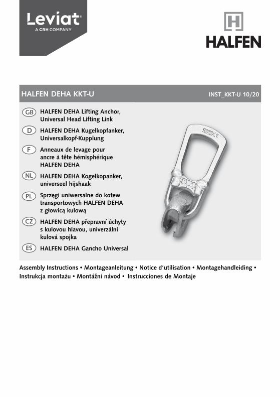
The universal head lifting link is identifi ed with the name of the manufacturer (HALFEN DEHA) stamped into the handle together with the application identifi er K-A and the unique anchor number. The load group, the CE marking and an operating symbol can be found on the rear of the handle.
The application identifi er K-A denotes that the universal head lifting link can be used for the following two HALFEN DEHA Lifting anchor systems:
• for the HALFEN DEHA Lifting anchor system type K with the spherical head anchor• for the HALFEN DEHA Lifting anchor system type A with an appropriate cast-in socket and adaptor.
Operatingicon
Batch no. year of productionIn house identifi er for the cast part
Load classCE marking
ManufacturerType K-A Manufacturer
Type K-A
Identifi cationnumber
Identifi cationnumber
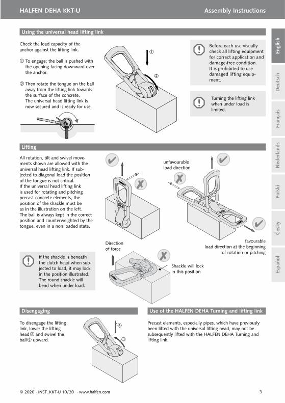
Before each use visually check all lifting equipment for correct application and damage-free condition. It is prohibited to use damaged lifting equipment.
Allocation of the Universal-head lifting link to the load classes of the anchors. (each lifting link is marked with the load class).
Anchor load class and correct lifting links
Anchor 1,3 2,5 4,0 5,0 7,5 10,0 15,0 20,0 32,0 45,0
Lifting link 1,3 2,5 5,0 10,0 20,0 32,0 45,0
l
g
at
Technical description
These assembly instructions apply to the HALFEN DEHA Universal-head lift-ing link together with the instructions for the HALFEN DEHA Spherical-head lifting anchor system.The system consists of the HALFEN DEHA Universal-head lifting link and the cast-in HALFEN DEHA Spherical-head lifting anchors. The HALFEN DEHA Universal-head lifting link is manually operated. The load groups and dimensions are listed in the following table.
The lifting link and the lifting anchor must both be of the same load group. If used to specifi cations, the dimen-sions of the various parts (including the recess former) ensure incorrect combinations are not possible. All work-safety regulations must be observed, particularly the European machine guideline (MD) 2006/42/EC and the VDI guideline VDI/BV-BS 6205.
Load capacities of the Universal-head lifting link, subject to varying load directions and dimensions
For load class Article nameOrder no. 0738.010-
Weight[kg]
Centric load
[kN]
Diagonal load ≥ 45°
[kN]
Shear load
[kN]a
[mm]g
[mm]l
[mm]t
[mm]
1,3 6102-1,3 00001 0.9 13.0 13.0 13.0 47 71 188 12
2,5 6102-2,5 00002 1.4 25.0 25.0 25.0 59 86 230 14
5,0 6102-5,0 00003 3.4 50.0 50.0 50.0 70 88 283 16
10,0 6102-10,0 00004 9.1 100.0 100.0 100.0 88 115 401 25
20,0 6102-20,0 00005 21.0 200.0 200.0 200.0 106 135 506 30
32,0 6102-32,0 00006 47.0 320.0 320.0 320.0 172 189 680 40
45,0 6102-45,0 00007 59.0 450.0 450.0 450.0 179 192 676 40
3© 2020 · INST_KKT-U 10/20 · www.halfen.com
HALFEN DEHA KKT-U Assembly Instructions
Deu
tsch
Engl
ish
Fran
çais
Ned
erla
nds
Pols
kiČ
esky
Espa
ñol
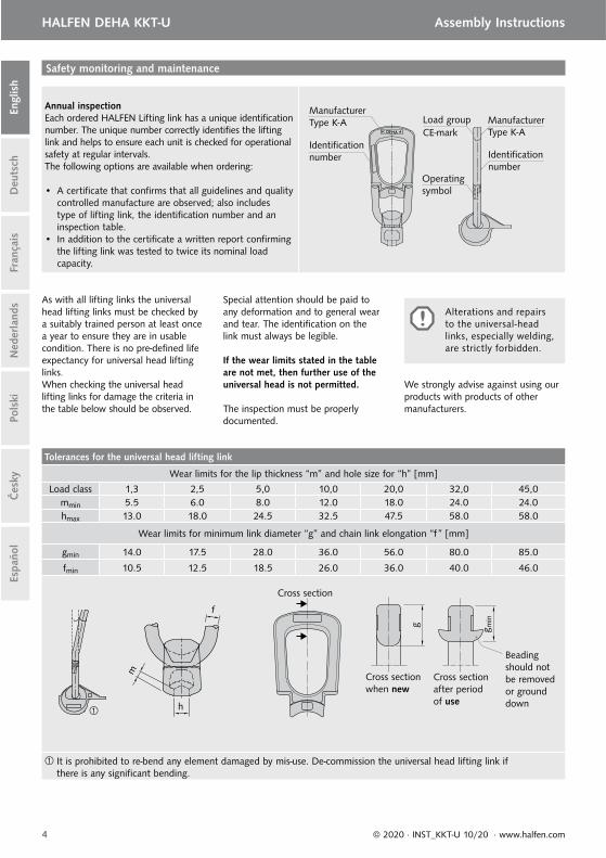
All rotation, tilt and swivel move-ments shown are allowed with the universal head lifting link. If sub-jected to diagonal load the position of the tongue is not critical.If the universal head lifting link is used for rotating and pitching precast concrete elements, the position of the shackle must be as in the illustration on the left.The ball is always kept in the correct position and counterweighted by the tongue, even in a non loaded state.
To disengage the lifting link, lower the lifting head and swivel the ball upward.
unfavourable load direction
favourableload direction at the beginning
of rotation or pitching
Use of the HALFEN DEHA Turning and lifting linkDisengaging
Using the universal head lifting link
Lifting
Turning the lifting link when under load is limited.
Precast elements, especially pipes, which have previously been lifted with the universal lifting head, may not be subsequently lifted with the HALFEN DEHA Turning and lifting link.
Check the load capacity of the anchor against the lifting link.
To engage; the ball is pushed with the opening facing downward over the anchor.
Then rotate the tongue on the ball away from the lifting link towards the surface of the concrete.The universal head lifting link is now secured and is ready for use.
If the shackle is beneath the clutch head when sub-jected to load, it may lock in the position illustrated. The round shackle will bend when under load.
Shackle will lockin this position
Direction of force
Before each use visually check all lifting equipment for correct application and damage-free condition. It is prohibited to use damaged lifting equip-ment.
4 © 2020 · INST_KKT-U 10/20 · www.halfen.com
HALFEN DEHA KKT-U Assembly InstructionsD
euts
chEn
glis
hFr
ança
isN
eder
land
sPo
lski
Čes
kyEs
paño
l
Annual inspectionEach ordered HALFEN Lifting link has a unique identifi cation number. The unique number correctly identifi es the lifting link and helps to ensure each unit is checked for operational safety at regular intervals. The following options are available when ordering:
• A certifi cate that confi rms that all guidelines and quality controlled manufacture are observed; also includes type of lifting link, the identifi cation number and an inspection table.
• In addition to the certifi cate a written report confi rming the lifting link was tested to twice its nominal load capacity.
Safety monitoring and maintenance
Operatingsymbol
ManufacturerType K-A
Load groupManufacturerType K-A
Identifi cationnumber Identifi cation
number
As with all lifting links the universal head lifting links must be checked by a suitably trained person at least once a year to ensure they are in usable condition. There is no pre-defi ned life expectancy for universal head lifting links.When checking the universal head lifting links for damage the criteria in the table below should be observed.
Special attention should be paid to any deformation and to general wear and tear. The identifi cation on the link must always be legible.
If the wear limits stated in the table are not met, then further use of the universal head is not permitted.
The inspection must be properly documented.
CE-mark
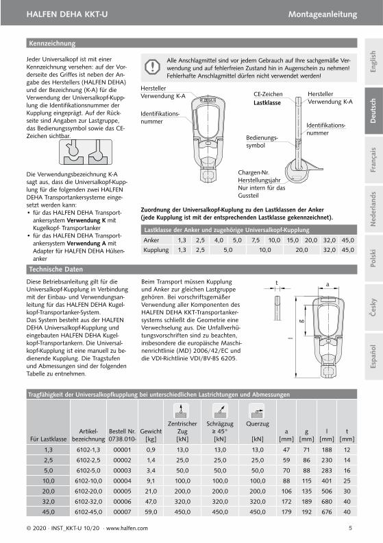
Tolerances for the universal head lifting link
Wear limits for the lip thickness “m” and hole size for “h” [mm]
Load class 1,3 2,5 5,0 10,0 20,0 32,0 45,0mmin 5.5 6.0 8.0 12.0 18.0 24.0 24.0hmax 13.0 18.0 24.5 32.5 47.5 58.0 58.0
Wear limits for minimum link diameter “g” and chain link elongation “f ” [mm]
gmin 14.0 17.5 28.0 36.0 56.0 80.0 85.0
fmin 10.5 12.5 18.5 26.0 36.0 40.0 46.0
It is prohibited to re-bend any element damaged by mis-use. De-commission the universal head lifting link if there is any signifi cant bending.
h
m
f
Beading should not be removed or ground down
g
Cross section when new
g min
Cross sectionafter period of use
Cross section
Alterations and repairs to the universal-head links, especially welding, are strictly forbidden.
We strongly advise against using our products with products of other manufacturers.
5© 2020 · INST_KKT-U 10/20 · www.halfen.com
Deu
tsch
HALFEN DEHA KKT-U Montageanleitung
Engl
ish
Fran
çais
Ned
erla
nds
Pols
kiČ
esky
Espa
ñol
Kennzeichnung
Jeder Universalkopf ist mit einer Kennzeichnung versehen: auf der Vor-derseite des Griff es ist neben der An-gabe des Herstellers (HALFEN DEHA) und der Bezeichnung (K-A) für die Verwendung der Universalkopf-Kupp-lung die Identifi kationsnummer der Kupplung eingeprägt. Auf der Rück-seite sind Angaben zur Lastgruppe, das Bedienungssymbol sowie das CE-Zeichen sichtbar.
Die Verwendungsbezeichnung K-A sagt aus, dass die Universalkopf-Kupp-lung für die folgenden zwei HALFEN DEHA Transportankersysteme einge-setzt werden kann: • für das HALFEN DEHA Transport-
ankersystem Verwendung K mit Kugelkopf- Transportanker
• für das HALFEN DEHA Transport-ankersystem Verwendung A mit Adapter für HALFEN DEHA Hülsen-anker
Bedienungs-symbol
Chargen-Nr. HerstellungsjahrNur intern für das Gussteil
LastklasseCE-Zeichen
HerstellerVerwendung K-A Hersteller
Verwendung K-A
Identifi kations-nummer
Identifi kations-nummer
l
g
at
Technische Daten
Diese Betriebsanleitung gilt für die Universalkopf-Kupplung in Verbindung mit der Einbau- und Verwendungsan-leitung für das HALFEN DEHA Kugel-kopf-Transportanker-System.Das System besteht aus der HALFEN DEHA Universalkopf-Kupplung und eingebauten HALFEN DEHA Kugel-kopf-Transportankern. Die Universal-kopf-Kupplung ist eine manuell zu be-dienende Kupplung. Die Tragstufen und Abmessungen sind der folgenden Tabelle zu entnehmen.
Beim Transport müssen Kupplung und Anker zur gleichen Lastgruppe gehören. Bei vorschriftsgemäßer Verwendung aller Komponenten des HALFEN DEHA KKT-Transportanker-systems schließt die Geometrie eine Verwechselung aus. Die Unfallverhü-tungsvorschriften sind zu beachten, insbesondere die europäische Maschi-nenrichtlinie (MD) 2006/42/EC und die VDI-Richtlinie VDI/BV-BS 6205.
Alle Anschlagmittel sind vor jedem Gebrauch auf Ihre sachgemäße Ver-wendung und auf fehlerfreien Zustand hin in Augenschein zu nehmen! Fehlerhafte Anschlagmittel dürfen nicht verwendet werden!
Zuordnung der Universalkopf-Kuplung zu den Lastklassen der Anker (jede Kupplung ist mit der entsprechenden Lastklasse gekennzeichnet).
Lastklasse der Anker und zugehörige Universalkopf-Kupplung
Anker 1,3 2,5 4,0 5,0 7,5 10,0 15,0 20,0 32,0 45,0
Kupplung 1,3 2,5 5,0 10,0 20,0 32,0 45,0
Tragfähigkeit der Universalkopfkupplung bei unterschiedlichen Lastrichtungen und Abmessungen
Für LastklasseArtikel-
bezeichnungBestell Nr. 0738.010-
Gewicht[kg]
Zentrischer Zug[kN]
Schrägzug≥ 45°[kN]
Querzug
[kN]a
[mm]g
[mm]l
[mm]t
[mm]
1,3 6102-1,3 00001 0,9 13,0 13,0 13,0 47 71 188 12
2,5 6102-2,5 00002 1,4 25,0 25,0 25,0 59 86 230 14
5,0 6102-5,0 00003 3,4 50,0 50,0 50,0 70 88 283 16
10,0 6102-10,0 00004 9,1 100,0 100,0 100,0 88 115 401 25
20,0 6102-20,0 00005 21,0 200,0 200,0 200,0 106 135 506 30
32,0 6102-32,0 00006 47,0 320,0 320,0 320,0 172 189 680 40
45,0 6102-45,0 00007 59,0 450,0 450,0 450,0 179 192 676 40
6 © 2020 · INST_KKT-U 10/20 · www.halfen.com
Deu
tsch
HALFEN DEHA KKT-U Montageanleitung En
glis
hFr
ança
isN
eder
land
sPo
lski
Čes
kyEs
paño
l
Zum Lösen wird zunächst der Lasthaken abgelassen. Die Kugel wird nach oben herausgedreht und die Universalkopf-Kupplung kann abgehoben werden .
Dreh- und TransportkupplungLösen
Einkuppeln
Das Drehen der Kupplung unter Last ist nur einge-schränkt möglich.
Bei Fertigteilen, die mit der Dreh- und Transportkupplung transportiert werden sollen, insbesondere bei Rohren, darf vorher nicht die Universalkopfkupplung verwendet werden.
Lastangabe auf dem Anker mit der Angabe auf der Universalkopf-Kupp-lung vergleichen.
Zum Einsetzen wird die Kugel mit ihrer Öff nung nach unten über den Anker geschoben.
Dann wird die Lasche der Kugel zur Betonoberfl äche gedreht.Der Universalkopf sitzt in der Ausspa-rung und ist nun einsatzbereit.
Mit der Universalkopf-Kupplung ist die dargestellte Dreh-, Kipp- und Schwenkbewegung erlaubt und unbe-denklich. Bei Schrägzug ist jede Stellung des Griff s erlaubt. Wird die Universalkopf-Kupplung zum Drehen und Aufrichten von Be-tonfertigteilen verwandt, muss die Lage der Lasche der Abbildung links entsprechen.Durch das Gegengewicht der Lasche wird die Kugel, auch in unbelastetem Zustand, stets in der richtigen Lage gehalten.
ungünstige Lastrichtung
günstige Lastrichtung bei Beginn des Dreh- oder Aufrichtvorgangs
Heben
Wenn der Bügel beim Be-lasten unter dem Kupp-lungskopf liegt, kann er in der dargestellten Position blockieren. Beim Abheben wird dann der Rundbügel verbogen.
Bügel blockiert in dieser Position
Kraftrichtung
Alle Anschlagmittel sind vor jedem Gebrauch auf Ihre sachgemäße Verwendung und auf fehlerfreien Zu-stand hin in Augenschein zu nehmen! Fehlerhafte Anschlagmittel dürfen nicht verwendet werden!
7© 2020 · INST_KKT-U 10/20 · www.halfen.com
Deu
tsch
HALFEN DEHA KKT-U Montageanleitung
Engl
ish
Fran
çais
Ned
erla
nds
Pols
kiČ
esky
Espa
ñol
Jährliche KontrolleJeder bestellte Abheber ist zur einfachen Identifi kation bei der regelmäßigen Überprüfung der Einsatzfähigkeit mit einer Identifi kationsnummer gekennzeichnet. Zusätzlich können folgende Optionen bei der Bestellung ausgewählt werden:
• Zertifi kat, das die Einhaltung sämtlicher Richtlinien und die überwachte Herstellung bestätigt, Abhebertyp, Identifi kationsnummer sowie eine Tabelle für die regel-mäßige Überprüfung enthält.
• Zusätzlich zum Zertifi kat kann eine dokumentierte Prü-fung des Abhebers auf 2-fache Nenntragfähigkeit erfol-gen.
Prüfvorschrift - Universalkopf-Kupplung
Bedienungs-symbol
LastgruppeHerstellerVerwendung K-A Hersteller
Verwendung K-AIdentifi kations- nummer Identifi kations-
nummer
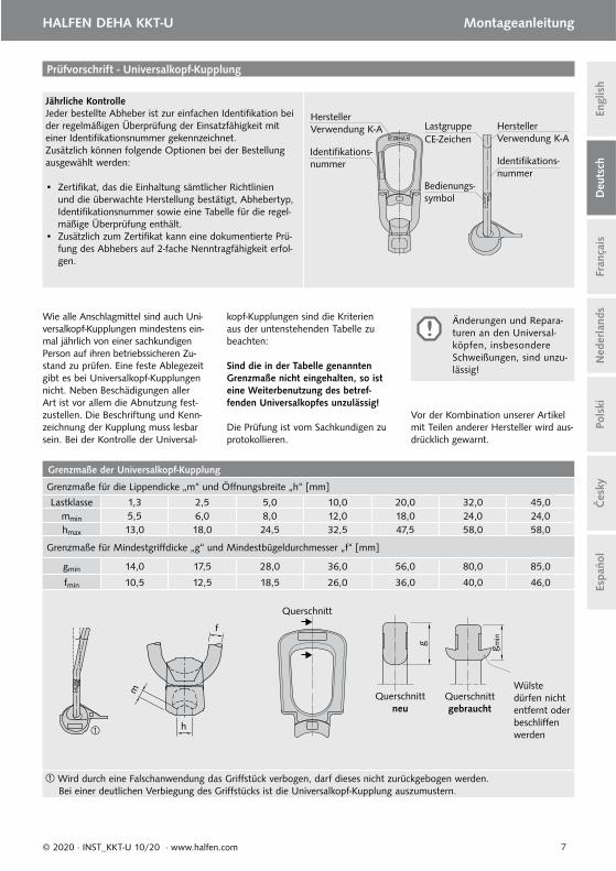
Wie alle Anschlagmittel sind auch Uni-versalkopf-Kupplungen mindestens ein-mal jährlich von einer sachkundigen Person auf ihren betriebssicheren Zu-stand zu prüfen. Eine feste Ablegezeit gibt es bei Universalkopf-Kupplungen nicht. Neben Beschädigungen aller Art ist vor allem die Abnutzung fest-zustellen. Die Beschriftung und Kenn-zeichnung der Kupplung muss lesbar sein. Bei der Kontrolle der Universal-
kopf-Kupplungen sind die Kriterien aus der untenstehenden Tabelle zu beachten:
Sind die in der Tabelle genannten Grenzmaße nicht eingehalten, so ist eine Weiterbenutzung des betref-fenden Universalkopfes unzulässig!
Die Prüfung ist vom Sachkundigen zu protokollieren.
CE-Zeichen
Grenzmaße der Universalkopf-Kupplung
Grenzmaße für die Lippendicke „m“ und Öff nungsbreite „h“ [mm]
Lastklasse 1,3 2,5 5,0 10,0 20,0 32,0 45,0mmin 5,5 6,0 8,0 12,0 18,0 24,0 24,0hmax 13,0 18,0 24,5 32,5 47,5 58,0 58,0
Grenzmaße für Mindestgriff dicke „g“ und Mindestbügeldurchmesser „f“ [mm]
gmin 14,0 17,5 28,0 36,0 56,0 80,0 85,0
fmin 10,5 12,5 18,5 26,0 36,0 40,0 46,0
Wird durch eine Falschanwendung das Griff stück verbogen, darf dieses nicht zurückgebogen werden. Bei einer deutlichen Verbiegung des Griff stücks ist die Universalkopf-Kupplung auszumustern.
h
m
f
Wülste dürfen nicht entfernt oder beschliff en werden
g
Querschnitt neu
g min
Querschnitt gebraucht
Querschnitt
Änderungen und Repara-turen an den Universal-köpfen, insbesondere Schweißungen, sind unzu-lässig!
Vor der Kombination unserer Artikel mit Teilen anderer Hersteller wird aus-drücklich gewarnt.
8 © 2020 · INST_KKT-U 10/20 · www.halfen.com
Deu
tsch
Engl
ish
Fran
çais
HALFEN DEHA KKT-U Notice d‘utilisation N
eder
land
sPo
lski
Čes
kyEs
paño
l
Marquage
Chaque anneau de levage est identi-fi able avec les marques suivantes : Le nom du fabricant (HALFEN DEHA) est gravé d'un coté de la boucle de l’anneau au même endroit que l’iden-tifi ant du type d’anneau K-A ainsi que le numéro unique d’identifi cation. La catégorie de charge, le marquage CE et le symbole d’explication d’utilisa-tion se trouvent sur l'autre côté de la boucle de l’anneau de levage.
Le marquage K-A signifi e que l’an-neau universel peut être utilisé avec les deux systèmes de levage suivants:
• pour le système de levage HALFEN DEHA de type K avec les ancres de levage à tête hémisphérique et,• pour le système de levage HALFEN DEHA de type A avec adaptateur type 6303 ou 6366 et la douille de levage appropriée.
Symboled‘utilisation
Numéro de lot Année de productionN° d'identifi cation unique de la noix moulée de l'anneau de levage
Catégorie de charge
Marquage CEFabricantType K-A Fabricant
Type K-A
N° d’identifi ca-tion
N° d’identifi ca-tion
Avant chaque utilisation, il convient de vérifi er visuellement les équipe-ments de levage, ceci afi n d’avoir un usage correct et sans dommage. Il est interdit d’utiliser des équipements de levage endommagés.
A chaque anneau de levage est attribué une capacité portante de l'ancre (chaque anneau de levage est identifi é par une classe de charge).
Classes de charges des anneaux de levage en fonction du type d'ancre
Ancre 1,3 2,5 4,0 5,0 7,5 10,0 15,0 20,0 32,0 45,0
Anneau de levage 1,3 2,5 5,0 10,0 20,0 32,0 45,0
l
g
at
Description technique
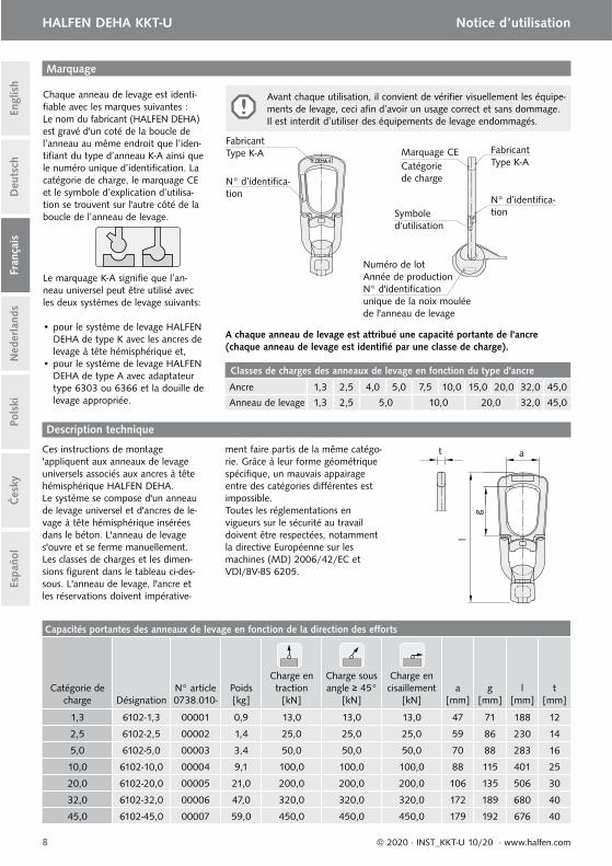
Ces instructions de montage 'appliquent aux anneaux de levage universels associés aux ancres à tête hémisphérique HALFEN DEHA. Le système se compose d'un anneau de levage universel et d'ancres de le-vage à tête hémisphérique insérées dans le béton. L'anneau de levage s'ouvre et se ferme manuellement. Les classes de charges et les dimen-sions fi gurent dans le tableau ci-des-sous. L'anneau de levage, l'ancre et les réservations doivent impérative-
ment faire partis de la même catégo-rie. Grâce à leur forme géométrique spécifi que, un mauvais appairage entre des catégories diff érentes est impossible.Toutes les réglementations en vigueurs sur le sécurité au travail doivent être respectées, notamment la directive Européenne sur les machines (MD) 2006/42/EC et VDI/BV-BS 6205.
Capacités portantes des anneaux de levage en fonction de la direction des eff orts
Catégorie de charge Désignation
N° article0738.010-
Poids[kg]
Charge en traction
[kN]
Charge sous angle ≥ 45°
[kN]
Charge en cisaillement
[kN]a
[mm]g
[mm]l
[mm]t
[mm]
1,3 6102-1,3 00001 0,9 13,0 13,0 13,0 47 71 188 12
2,5 6102-2,5 00002 1,4 25,0 25,0 25,0 59 86 230 14
5,0 6102-5,0 00003 3,4 50,0 50,0 50,0 70 88 283 16
10,0 6102-10,0 00004 9,1 100,0 100,0 100,0 88 115 401 25
20,0 6102-20,0 00005 21,0 200,0 200,0 200,0 106 135 506 30
32,0 6102-32,0 00006 47,0 320,0 320,0 320,0 172 189 680 40
45,0 6102-45,0 00007 59,0 450,0 450,0 450,0 179 192 676 40
9© 2020 · INST_KKT-U 10/20 · www.halfen.com
Deu
tsch
Engl
ish
Fran
çais
HALFEN DEHA KKT-U Notice d‘utilisation
Ned
erla
nds
Pols
kiČ
esky
Espa
ñol
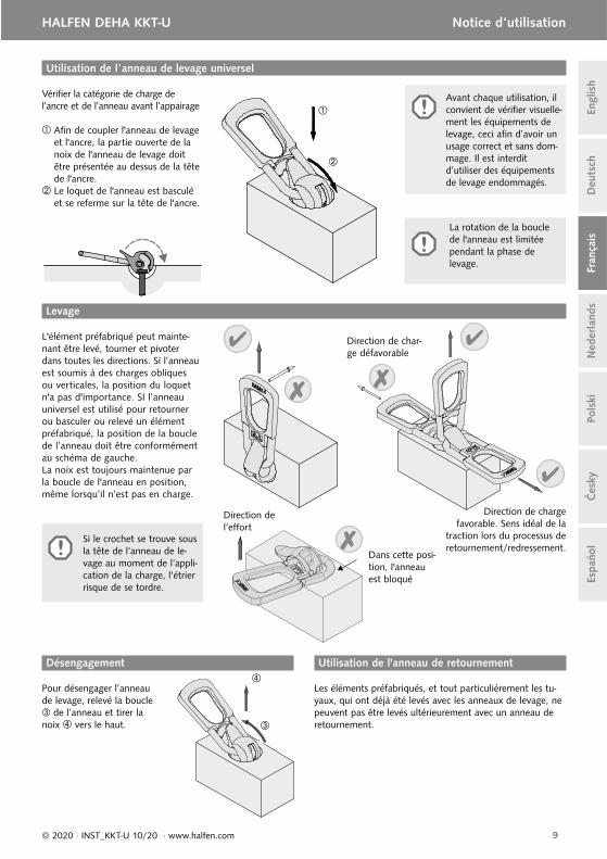
Pour désengager l’anneau de levage, relevé la boucle
de l’anneau et tirer la noix vers le haut.
Désengagement
Utilisation de l’anneau de levage universel
La rotation de la boucle de l'anneau est limitée pendant la phase de levage.
Vérifi er la catégorie de charge de l’ancre et de l’anneau avant l’appairage
Afi n de coupler l'anneau de levage et l'ancre, la partie ouverte de la noix de l'anneau de levage doit être présentée au dessus de la tête de l'ancre. Le loquet de l'anneau est basculé et se referme sur la tête de l'ancre.
L'élément préfabriqué peut mainte-nant être levé, tourner et pivoter dans toutes les directions. Si l’anneau est soumis à des charges obliques ou verticales, la position du loquet n'a pas d'importance. SI l’anneau universel est utilisé pour retourner ou basculer ou relevé un élément préfabriqué, la position de la boucle de l’anneau doit être conformément au schéma de gauche.La noix est toujours maintenue par la boucle de l'anneau en position, même lorsqu’il n’est pas en charge.
Levage
Direction de char-ge défavorable
Direction de charge favorable. Sens idéal de la
traction lors du processus de retournement/redressement.
Si le crochet se trouve sous la tête de l‘anneau de le-vage au moment de l‘appli-cation de la charge, l‘étrier risque de se tordre.
Dans cette posi-tion, l'anneau est bloqué
Direction de l‘eff ort
Utilisation de l'anneau de retournement
Les éléments préfabriqués, et tout particulièrement les tu-yaux, qui ont déjà été levés avec les anneaux de levage, ne peuvent pas être levés ultérieurement avec un anneau de retournement.
Avant chaque utilisation, il convient de vérifi er visuelle-ment les équipements de levage, ceci afi n d’avoir un usage correct et sans dom-mage. Il est interdit d’utiliser des équipements de levage endommagés.
10 © 2020 · INST_KKT-U 10/20 · www.halfen.com
Deu
tsch
Engl
ish
Fran
çais
HALFEN DEHA KKT-U Notice d‘utilisation N
eder
land
sPo
lski
Čes
kyEs
paño
l
Inspection annuelleChaque anneau de levage commandé comporte un numéro unique d’identifi cation. Ce numéro unique identifi e l’anneau de levage et aide à s’assurer que chaque anneau fasse l’objet de vérifi cation de sécurité à intervalles réguliers.Les options supplémentaires suivantes sont possible lors de la commande :• Un certifi cat de conformité attestant que toutes
les directives et tous les contrôles lors de la fabri-cation sont respectés, ce qui inclut également le type d’anneau de levage, le numéro d’identifi ca-tion et le contrôle.
• Un certifi cat de conformité spécifi que à l'anneau qui garantie que l’anneau de levage à été testé par deux fois à sa capacité de charge nominale.
Surveillance de la sécurité et de maintenance
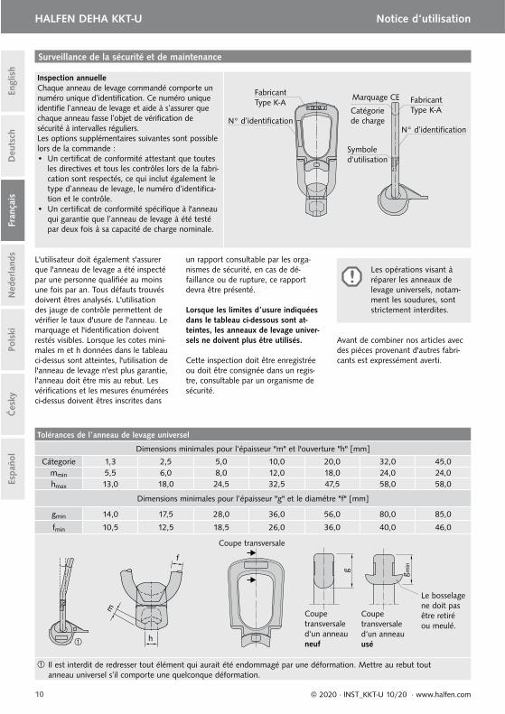
L'utilisateur doit également s'assurer que l'anneau de levage a été inspecté par une personne qualifi ée au moins une fois par an. Tous défauts trouvés doivent êtres analysés. L'utilisation des jauge de contrôle permettent de vérifi er le taux d'usure de l'anneau. Le marquage et l'identifi cation doivent restés visibles. Lorsque les cotes mini-males m et h données dans le tableau ci-dessus sont atteintes, l'utilisation de l'anneau de levage n'est plus garantie, l'anneau doit être mis au rebut. Les vérifi cations et les mesures énumérées ci-dessus doivent êtres inscrites dans
un rapport consultable par les orga-nismes de sécurité, en cas de dé-faillance ou de rupture, ce rapport devra être présenté.
Lorsque les limites d’usure indiquées dans le tableau ci-dessous sont at-teintes, les anneaux de levage univer-sels ne doivent plus être utilisés.
Cette inspection doit être enregistrée ou doit être consignée dans un regis-tre, consultable par un organisme de sécurité.
Tolérances de l’anneau de levage universel
Dimensions minimales pour l‘épaisseur "m" et l'ouverture "h" [mm]
Cátegorie 1,3 2,5 5,0 10,0 20,0 32,0 45,0mmin 5,5 6,0 8,0 12,0 18,0 24,0 24,0hmax 13,0 18,0 24,5 32,5 47,5 58,0 58,0
Dimensions minimales pour l‘épaisseur "g" et le diamétre "f" [mm]
gmin 14,0 17,5 28,0 36,0 56,0 80,0 85,0
fmin 10,5 12,5 18,5 26,0 36,0 40,0 46,0
Il est interdit de redresser tout élément qui aurait été endommagé par une déformation. Mettre au rebut tout anneau universel s’il comporte une quelconque déformation.
h
m
f
Le bosselage ne doit pas être retiréou meulé.
g
Coupe transversale d‘un anneau neuf
g min
Coupe transversaled‘un anneau usé
Coupe transversale
Les opérations visant à réparer les anneaux de levage universels, notam-ment les soudures, sontstrictement interdites.
Symboled‘utilisation
Catégorie de charge
Marquage CEFabricantType K-A Fabricant
Type K-AN° d’identifi cation
N° d’identifi cation
Avant de combiner nos articles avec des pièces provenant d'autres fabri-cants est expressément averti.
11© 2020 · INST_KKT-U 10/20 · www.halfen.com
HALFEN DEHA KKT-U Montagehandleiding
Deu
tsch
Engl
ish
Fran
çais
Ned
erla
nds
Pols
kiČ
esky
Espa
ñol
Markering
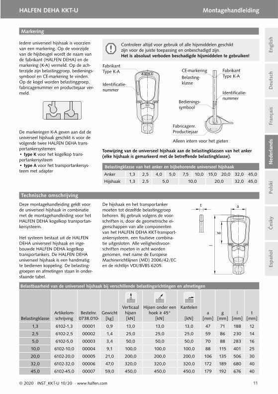
Iedere universeel hijshaak is voorzien van een markering. Op de voorzijde van de hijsbeugel wordt de naam van de fabrikant (HALFEN DEHA) en de markering (K-A) vermeld. Op de ach-terzijde zijn belastinggroep, bedienings-symbool en CE-markering te vinden. Op de kogel worden belastinggroep, fabricagenummer en productiejaar ver-meld.
De markeringen K-A geven aan dat de universeel hijshaak geschikt is voor de volgende twee HALFEN DEHA trans-portankersystemen:• type K voor het kogelkop trans-portankersysteem• type A voor het transportankersys-teem met adapter
Bedienings-symbool
Fabricagenr.Productiejaar
Alleen intern voor het gieten
Belasting-klasse
CE-markeringFabrikantType K-A Fabrikant
Type K-A
Identifi catie-nummer
Identifi catie-nummer
l
g
at
Technische omschrijving
Deze montagehandleiding geldt voor de universeel hijshaak in combinatie met de montagehandleiding voor het HALFEN DEHA kogelkop transportan-kersysteem.
Het systeem bestaat uit de HALFEN DEHA universeel hijshaak en inge-bouwde HALFEN DEHA kogelkop transportankers. De HALFEN DEHA universeel hijshaak is een handmatig te bedienen koppeling. De belasting-groepen en afmetingen staan in onder-staande tabel.
De hijshaak en het transportanker moeten tot dezelfde belastinggroep behoren. Bij gebruik volgens de voor-schriften is, door de geometrische ei-genschappen van alle componenten van het HALFEN DEHA KKT-transport-ankersysteem, een foutieve combina-tie uitgesloten. Alle veiligheidsvoor-schriften moeten in acht worden genomen, met name de Europese Machinerichtlijnen (MD) 2006/42/EC en de richtlijn VDI/BVBS 6205.
Controleer altijd voor gebruik of alle hijsmiddelen geschikt zijn voor de juiste toepassing en onbeschadigd zijn.Het is absoluut verboden beschadigde hijsmiddelen te gebruiken!
Toewijzing van de universeel hijshaak aan de belastingklassen van het anker(elke hijshaak is gemarkeerd met de betreff ende belastingklasse).
Belastingklasse van het anker en bijbehorende universeel hijshaak
Anker 1,3 2,5 4,0 5,0 7,5 10,0 15,0 20,0 32,0 45,0
Hijshaak 1,3 2,5 5,0 10,0 20,0 32,0 45,0
Belastbaarheid van de universeel hijshaak bij verschillende belastingsrichtingen en afmetingen
BelastingklasseArtikelom-schrijving
Bestelnr. 0738.010-
Gewicht[kg]
Verticaal hijsen [kN]
Hijsen onder een hoek ≥ 45°
[kN]
Kantelen
[kN]a
[mm]g
[mm]l
[mm]t
[mm]
1,3 6102-1,3 00001 0,9 13,0 13,0 13,0 47 71 188 12
2,5 6102-2,5 00002 1,4 25,0 25,0 25,0 59 86 230 14
5,0 6102-5,0 00003 3,4 50,0 50,0 50,0 70 88 283 16
10,0 6102-10,0 00004 9,1 100,0 100,0 100,0 88 115 401 25
20,0 6102-20,0 00005 21,0 200,0 200,0 200,0 106 135 506 30
32,0 6102-32,0 00006 47,0 320,0 320,0 320,0 172 189 680 40
45,0 6102-45,0 00007 59,0 450,0 450,0 450,0 179 192 676 40

12 © 2020 · INST_KKT-U 10/20 · www.halfen.com
HALFEN DEHA KKT-U Montagehandleiding D
euts
chEn
glis
hFr
ança
isN
eder
land
sPo
lski
Čes
kyEs
paño
l
Om de universeel hijshaak te ontkoppelen wordt de hijskabel gevierd. De aanslaglip wordt naar boven gedraaid en de hijshaak kan verwijderd worden .
Draai- en transportkoppelingOntkoppelen
Gebruik van de universeel hijshaak
Draaien van de hijshaak onder belasting is slechts beperkt mogelijk.
Voor prefab elementen die met de draai- en transportkop-peling getransporteerd worden geldt, in het bijzonder voor buizen, dat de universeel hijshaak niet vooraf gebruikt moet worden.
Controleer de belastbaarheid van het anker met de specifi caties op de uni-verseel hijshaak.
Voor het aanslaan wordt de kogel met zijn sparing naar onderen over de transportankerkop geplaatst.
De kogel daarna met de hand aan-draaien tot de aanslaglip op de beton rust. De kogel van de universeel hijs-haak zit nu in de uitsparing en de uni-verseel hijshaak is gebruiksklaar.
Alle afgebeelde draai-, hijs- en kantel-richtingen zijn toegestaan met de universeel hijshaak. De aanslaglip dient altijd met zijn platte zijde tegen de beton te rusten. Indien de universeel hijshaak wordt gebruikt om een betonelement te kantelen, dan moet de hijshaak ge-positioneerd zijn als de afbeelding links.Door het tegengewicht van de aan-slaglip bevindt de kogel zich altijd in de juiste positie, ook als deze niet belast wordt.
ongunstige belastingsrichting
gunstige belastingsrichting voor het draaien of hijsen
Hijsen
Als de beugel zich tijdens belasten onder de koppe-lingskop bevindt, kan deze blokkeren in de afge-beelde positie. De beugel zal dan buigen onder bela-sting.
beugel blokkeert in deze positie
krachtrichting
Controleer altijd voor gebruik of alle hijsmiddelen geschikt zijn voor de juiste toepassing en onbeschadigd zijn.Het is absoluut verboden beschadigde hijsmiddelen te gebruiken!
13© 2020 · INST_KKT-U 10/20 · www.halfen.com
HALFEN DEHA KKT-U Montagehandleiding
Deu
tsch
Engl
ish
Fran
çais
Ned
erla
nds
Pols
kiČ
esky
Espa
ñol
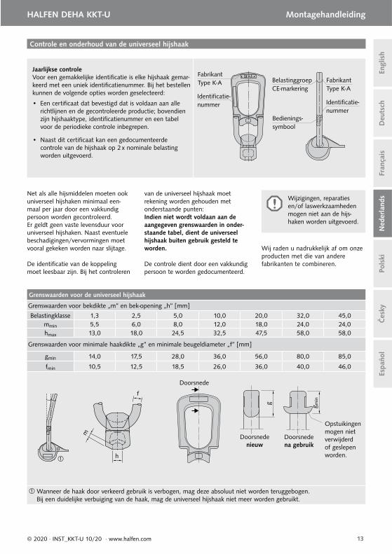
Jaarlijkse controleVoor een gemakkelijke identifi catie is elke hijshaak gemar-keerd met een uniek identifi catienummer. Bij het bestellen kunnen de volgende opties worden geselecteerd:
• Een certifi caat dat bevestigd dat is voldaan aan alle richtlijnen en de gecontroleerde productie; bovendien zijn hijshaaktype, identifi catienummer en een tabel voor de periodieke controle inbegrepen.
• Naast dit certifi caat kan een gedocumenteerde controle van de hijshaak op 2 x nominale belasting worden uitgevoerd.
Controle en onderhoud van de universeel hijshaak
Bedienings-symbool
BelastinggroepCE-markering
FabrikantType K-A Fabrikant
Type K-AIdentifi catie-nummer Identifi catie-
nummer
Net als alle hijsmiddelen moeten ook universeel hijshaken minimaal een-maal per jaar door een vakkundig persoon worden gecontroleerd. Er geldt geen vaste levensduur voor universeel hijshaken. Naast eventuele beschadigingen/vervormingen moet vooral gekeken worden naar slijtage.
De identifi catie van de koppeling moet leesbaar zijn. Bij het controleren
van de universeel hijshaak moet rekening worden gehouden met onderstaande punten:Indien niet wordt voldaan aan de aangegeven grenswaarden in onder-staande tabel, dient de universeel hijshaak buiten gebruik gesteld te worden.
De controle dient door een vakkundig persoon te worden gedocumenteerd.
Grenswaarden voor de universeel hijshaak
Grenswaarden voor bekdikte „m“ en bek-opening „h“ [mm]
Belastingklasse 1,3 2,5 5,0 10,0 20,0 32,0 45,0mmin 5,5 6,0 8,0 12,0 18,0 24,0 24,0hmax 13,0 18,0 24,5 32,5 47,5 58,0 58,0
Grenswaarden voor minimale haakdikte „g“ en minimale beugeldiameter „f“ [mm]
gmin 14,0 17,5 28,0 36,0 56,0 80,0 85,0
fmin 10,5 12,5 18,5 26,0 36,0 40,0 46,0
Wanneer de haak door verkeerd gebruik is verbogen, mag deze absoluut niet worden teruggebogen. Bij een duidelijke verbuiging van de haak, mag de universeel hijshaak niet meer worden gebruikt.
h
m
f
g
Doorsnede nieuw
g min
Doorsnede na gebruik
Doorsnede
Wijzigingen, reparaties en/of laswerkzaamheden mogen niet aan de hijs-haken worden uitgevoerd.
Wij raden u nadrukkelijk af om onze producten met die van andere fabrikanten te combineren.
Opstuikingen mogen niet verwijderd of geslepen worden.
14 © 2020 · INST_KKT-U 10/20 · www.halfen.com
HALFEN DEHA KKT-U Instrukcja montażu D
euts
chEn
glis
hFr
ança
isN
eder
land
sPo
lski
Čes
kyEs
paño
l
Identyfi kacja
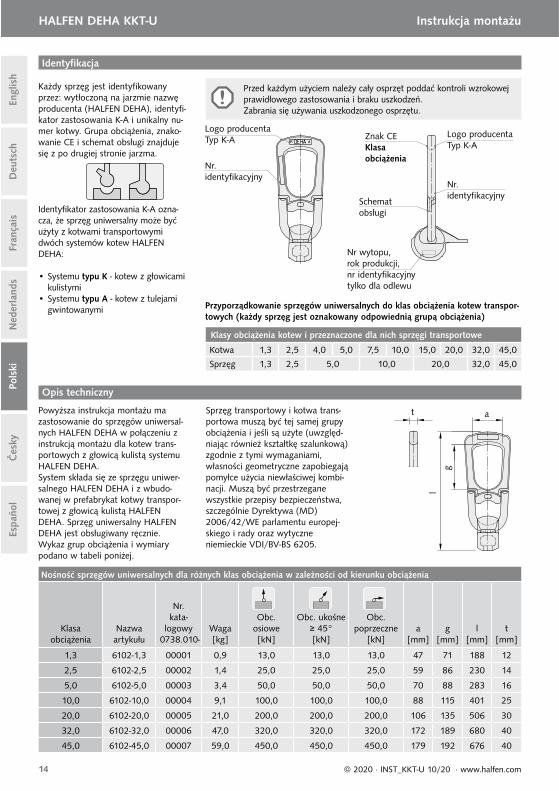
Każdy sprzęg jest identyfi kowany przez: wytłoczoną na jarzmie nazwę producenta (HALFEN DEHA), identyfi -kator zastosowania K-A i unikalny nu-mer kotwy. Grupa obciążenia, znako-wanie CE i schemat obsługi znajduje się z po drugiej stronie jarzma.
Identyfi kator zastosowania K-A ozna-cza, że sprzęg uniwersalny może być użyty z kotwami transportowymi dwóch systemów kotew HALFEN DEHA:
• Systemu typu K - kotew z głowicami kulistymi
• Systemu typu A - kotew z tulejami gwintowanymi
Schemat obsługi
Nr wytopu,rok produkcji, nr identyfi kacyjny tylko dla odlewu
Znak CEKlasaobciążenia
Logo producentaTyp K-A
Logo producentaTyp K-A
Nr.identyfi kacyjny
Nr. identyfi kacyjny
l
g
at
Opis techniczny
Powyższa instrukcja montażu ma zastosowanie do sprzęgów uniwersal-nych HALFEN DEHA w połączeniu z instrukcją montażu dla kotew trans-portowych z głowicą kulistą systemu HALFEN DEHA.System składa się ze sprzęgu uniwer-salnego HALFEN DEHA i z wbudo-wanej w prefabrykat kotwy transpor-towej z głowicą kulistą HALFEN DEHA. Sprzęg uniwersalny HALFEN DEHA jest obsługiwany ręcznie.Wykaz grup obciążenia i wymiary podano w tabeli poniżej.
Sprzęg transportowy i kotwa trans-portowa muszą być tej samej grupy obciążenia i jeśli są użyte (uwzględ-niając również kształtkę szalunkową) zgodnie z tymi wymaganiami, własności geometryczne zapobiegają pomyłce użycia niewłaściwej kombi-nacji. Muszą być przestrzegane wszystkie przepisy bezpieczeństwa, szczególnie Dyrektywa (MD) 2006/42/WE parlamentu europej-skiego i rady oraz wytyczne niemieckie VDI/BV-BS 6205.
Przed każdym użyciem należy cały osprzęt poddać kontroli wzrokowej prawidłowego zastosowania i braku uszkodzeń.Zabrania się używania uszkodzonego osprzętu.
Przyporządkowanie sprzęgów uniwersalnych do klas obciążenia kotew transpor-towych (każdy sprzęg jest oznakowany odpowiednią grupą obciążenia)
Klasy obciążenia kotew i przeznaczone dla nich sprzęgi transportowe
Kotwa 1,3 2,5 4,0 5,0 7,5 10,0 15,0 20,0 32,0 45,0
Sprzęg 1,3 2,5 5,0 10,0 20,0 32,0 45,0
Nośność sprzęgów uniwersalnych dla różnych klas obciążenia w zależności od kierunku obciążenia
Klasaobciążenia
Nazwaartykułu
Nr.kata-
logowy 0738.010-
Waga[kg]
Obc.osiowe[kN]
Obc. ukośne≥ 45°[kN]
Obc.poprzeczne
[kN]a
[mm]g
[mm]l
[mm]t
[mm]
1,3 6102-1,3 00001 0,9 13,0 13,0 13,0 47 71 188 12
2,5 6102-2,5 00002 1,4 25,0 25,0 25,0 59 86 230 14
5,0 6102-5,0 00003 3,4 50,0 50,0 50,0 70 88 283 16
10,0 6102-10,0 00004 9,1 100,0 100,0 100,0 88 115 401 25
20,0 6102-20,0 00005 21,0 200,0 200,0 200,0 106 135 506 30
32,0 6102-32,0 00006 47,0 320,0 320,0 320,0 172 189 680 40
45,0 6102-45,0 00007 59,0 450,0 450,0 450,0 179 192 676 40
15© 2020 · INST_KKT-U 10/20 · www.halfen.com
HALFEN DEHA KKT-U Instrukcja montażu
Deu
tsch
Engl
ish
Fran
çais
Ned
erla
nds
Pols
kiČ
esky
Espa
ñol
Opuścić głowicę i poprzez powrotny obrót części kulistej odblokować sprzęg.
Użycie sprzęgu do obracania i podnoszeniaRozprzęganie
Posługiwanie się sprzęgiem uniwersalnym
Obrót sprzęgu pod obciążeniem jest ograniczony.
Elementy prefabrykowane, szczególnie rury, które wcześniej były podnoszone z użyciem sprzęgu uniwersalnego nie mogą być później podnoszone z użyciem sprzęgu HALFEN DEHA do obracania i podnoszenia.
Sprawdzić nośność kotwy z grupą obciążenia sprzęgu.
Przy sprzęganiu część kulistą nałożyć otworem na głowicę kotwy.
Język części kulistej obrócić do momentu, aż przylgnie do po-wierzchni betonu.Sprzęg uniwersalny jest zamoco-wany i gotowy do użycia.
Użycie sprzęgów uniwersalnych po-zwala na obracanie, uchylanie prze-suwanie, przenoszenie zgodnie z pokazanymi schematami. Przy używaniu sprzęgu uniwersal-nego do obracania i podnoszenia elementów prefabrykowanych, jarz-mo musi być w położeniu jak na rysunku po lewej stronie.Przeciwwaga języka powoduje, że sprzęg nie wypnie się samoczynnie, nawet po zwolnieniu obciążenia.
Niewłaściwy kierunek obciążenia
Właściwy kierunek obciążenia
przy początkowym obra-caniu lub stawianiu.
Podnoszenie
Jeśli jarzmo jest pod głowicą sprzęgu i jest obciążone, może blokować się w pozycji pokazanej na rysunku. Przy podnoszeniu jarzmo ulegnie zgięciu.
Pozycja blokowania się jarzma
Kierunek obciążenia
Przed każdym użyciem należy cały osprzęt poddać kontroli wzrokowej prawidłowego zastosowania i braku uszkodzeń.Zabrania się używania usz-kodzonego osprzętu.
16 © 2020 · INST_KKT-U 10/20 · www.halfen.com
HALFEN DEHA KKT-U Instrukcja montażu D
euts
chEn
glis
hFr
ança
isN
eder
land
sPo
lski
Čes
kyEs
paño
l
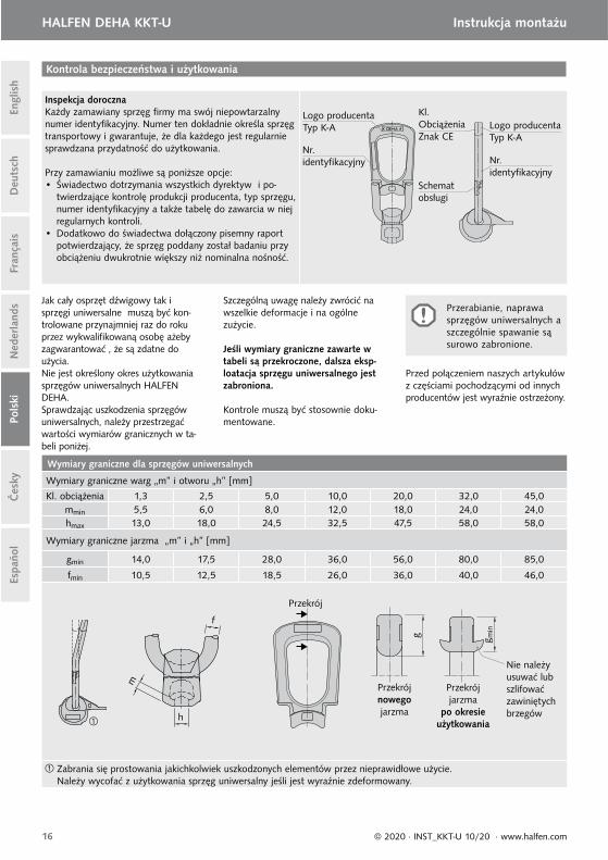
Inspekcja dorocznaKażdy zamawiany sprzęg fi rmy ma swój niepowtarzalny numer identyfi kacyjny. Numer ten dokładnie określa sprzęg transportowy i gwarantuje, że dla każdego jest regularnie sprawdzana przydatność do użytkowania.
Przy zamawianiu możliwe są poniższe opcje:• Świadectwo dotrzymania wszystkich dyrektyw i po-
twierdzające kontrolę produkcji producenta, typ sprzęgu, numer identyfi kacyjny a także tabelę do zawarcia w niej regularnych kontroli.
• Dodatkowo do świadectwa dołączony pisemny raport potwierdzający, że sprzęg poddany został badaniu przy obciążeniu dwukrotnie większy niż nominalna nośność.
Kontrola bezpieczeństwa i użytkowania
Kl. ObciążeniaZnak CE
Logo producentaTyp K-A Logo producenta
Typ K-ANr.identyfi kacyjny Nr.
identyfi kacyjny
Jak cały osprzęt dźwigowy tak i sprzęgi uniwersalne muszą być kon-trolowane przynajmniej raz do roku przez wykwalifi kowaną osobę ażeby zagwarantować , że są zdatne do użycia.Nie jest określony okres użytkowania sprzęgów uniwersalnych HALFEN DEHA.Sprawdzając uszkodzenia sprzęgów uniwersalnych, należy przestrzegać wartości wymiarów granicznych w ta-beli poniżej.
Szczególną uwagę należy zwrócić na wszelkie deformacje i na ogólne zużycie.
Jeśli wymiary graniczne zawarte w tabeli są przekroczone, dalsza eksp-loatacja sprzęgu uniwersalnego jest zabroniona.
Kontrole muszą być stosownie doku-mentowane.
Wymiary graniczne dla sprzęgów uniwersalnych
Wymiary graniczne warg „m” i otworu „h” [mm]
Kl. obciążenia 1,3 2,5 5,0 10,0 20,0 32,0 45,0mmin 5,5 6,0 8,0 12,0 18,0 24,0 24,0hmax 13,0 18,0 24,5 32,5 47,5 58,0 58,0
Wymiary graniczne jarzma „m” i „h” [mm]
gmin 14,0 17,5 28,0 36,0 56,0 80,0 85,0
fmin 10,5 12,5 18,5 26,0 36,0 40,0 46,0
Zabrania się prostowania jakichkolwiek uszkodzonych elementów przez nieprawidłowe użycie.Należy wycofać z użytkowania sprzęg uniwersalny jeśli jest wyraźnie zdeformowany.
h
m
f
Nie należy usuwać lub szlifować zawiniętych brzegów
g
Przekrój nowego jarzma
g min
Przekrój jarzma
po okresie użytkowania
Przekrój
Przerabianie, naprawa sprzęgów uniwersalnych a szczególnie spawanie są surowo zabronione.
Przed połączeniem naszych artykułówz częściami pochodzącymi od innych producentów jest wyraźnie ostrzeżony.
Schemat obsługi
17© 2020 · INST_KKT-U 10/20 · www.halfen.com
HALFEN DEHA KKT-U Montážní návod
Deu
tsch
Engl
ish
Fran
çais
Ned
erla
nds
Pols
kiEs
paño
lČ
esky
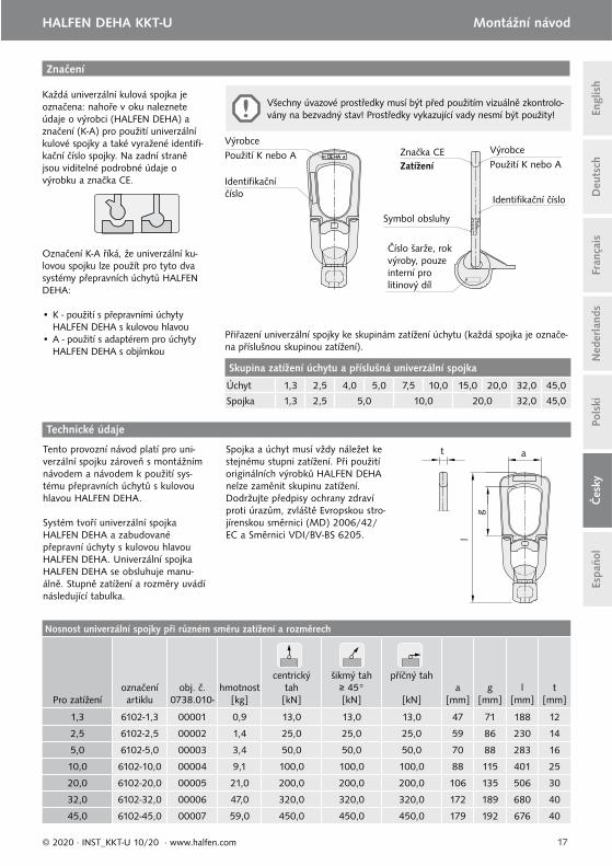
Značení
Každá univerzální kulová spojka je označena: nahoře v oku naleznete údaje o výrobci (HALFEN DEHA) a značení (K-A) pro použití univerzální kulové spojky a také vyražené identifi -kační číslo spojky. Na zadní straně jsou viditelné podrobné údaje o výrobku a značka CE.
Označení K-A říká, že univerzální ku-lovou spojku lze použít pro tyto dva systémy přepravních úchytů HALFEN DEHA:
• K - použití s přepravními úchyty HALFEN DEHA s kulovou hlavou • A - použití s adaptérem pro úchyty
HALFEN DEHA s objímkou
Symbol obsluhy
Číslo šarže, rok výroby, pouze interní prolitinový díl
Zatížení Značka CE
VýrobcePoužití K nebo A Výrobce
Použití K nebo A
Identifi kační číslo
Identifi kační číslo
l
g
at
Technické údaje
Tento provozní návod platí pro uni-verzální spojku zároveň s montážním návodem a návodem k použití sys-tému přepravních úchytů s kulovou hlavou HALFEN DEHA.
Systém tvoří univerzální spojka HALFEN DEHA a zabudované přepravní úchyty s kulovou hlavou HALFEN DEHA. Univerzální spojka HALFEN DEHA se obsluhuje manu-álně. Stupně zatížení a rozměry uvádí následující tabulka.
Spojka a úchyt musí vždy náležet ke stejnému stupni zatížení. Při použití originálních výrobků HALFEN DEHA nelze zaměnit skupinu zatížení.Dodržujte předpisy ochrany zdraví proti úrazům, zvláště Evropskou stro-jírenskou směrnici (MD) 2006/42/EC a Směrnici VDI/BV-BS 6205.
Všechny úvazové prostředky musí být před použitím vizuálně zkontrolo-vány na bezvadný stav! Prostředky vykazující vady nesmí být použity!
Přiřazení univerzální spojky ke skupinám zatížení úchytu (každá spojka je označe-na příslušnou skupinou zatížení).
Skupina zatížení úchytu a příslušná univerzální spojka
Úchyt 1,3 2,5 4,0 5,0 7,5 10,0 15,0 20,0 32,0 45,0
Spojka 1,3 2,5 5,0 10,0 20,0 32,0 45,0
Nosnost univerzální spojky při různém směru zatížení a rozměrech
Pro zatíženíoznačení artiklu
obj. č. 0738.010-
hmotnost[kg]
centrický tah[kN]
šikmý tah≥ 45°[kN]
příčný tah
[kN]a
[mm]g
[mm]l
[mm]t
[mm]
1,3 6102-1,3 00001 0,9 13,0 13,0 13,0 47 71 188 12
2,5 6102-2,5 00002 1,4 25,0 25,0 25,0 59 86 230 14
5,0 6102-5,0 00003 3,4 50,0 50,0 50,0 70 88 283 16
10,0 6102-10,0 00004 9,1 100,0 100,0 100,0 88 115 401 25
20,0 6102-20,0 00005 21,0 200,0 200,0 200,0 106 135 506 30
32,0 6102-32,0 00006 47,0 320,0 320,0 320,0 172 189 680 40
45,0 6102-45,0 00007 59,0 450,0 450,0 450,0 179 192 676 40
18 © 2020 · INST_KKT-U 10/20 · www.halfen.com
HALFEN DEHA KKT-U Montážní návod D
euts
chEn
glis
hFr
ança
isN
eder
land
sPo
lski
Espa
ñol
Čes
ky
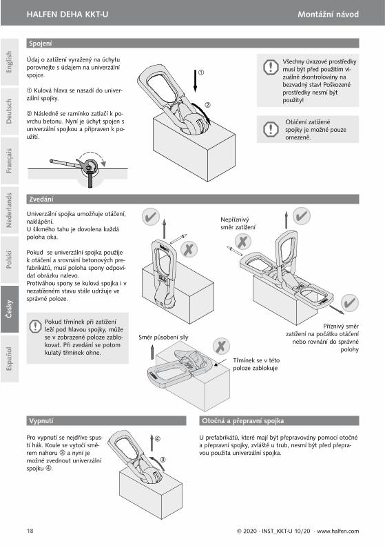
Pro vypnutí se nejdříve spus-tí hák. Koule se vytočí smě-rem nahoru a nyní je možné zvednout univerzální spojku .
Otočná a přepravní spojka Vypnutí
Spojení
Otáčení zatížené spojky je možné pouze omezeně.
U prefabrikátů, které mají být přepravovány pomocí otočné a přepravní spojky, zvláště u trub, nesmí být před přepra-vou použita univerzální spojka.
Údaj o zatížení vyražený na úchytu porovnejte s údajem na univerzální spojce.
Kulová hlava se nasadí do univer-zální spojky.
Následně se ramínko zatlačí k po-vrchu betonu. Nyní je úchyt spojen s univerzální spojkou a připraven k po-užití.
Univerzální spojka umožňuje otáčení, naklápění.U šikmého tahu je dovolena každá poloha oka.
Pokud se univerzální spojka použije k otáčení a srovnání betonových pre-fabrikátů, musí poloha spony odpoví-dat obrázku nalevo. Protiváhou spony se kulová spojka i v nezatíženém stavu stále udržuje ve správné poloze.
Nepříznivý směr zatížení
Příznivý směr zatížení na počátku otáčení
nebo rovnání do správné polohy
Zvedání
Pokud třmínek při zatížení leží pod hlavou spojky, může se v zobrazené poloze zablo-kovat. Při zvedání se potom kulatý třmínek ohne.
Třmínek se v této poloze zablokuje
Směr působení síly
Všechny úvazové prostředky musí být před použitím vi-zuálně zkontrolovány na bezvadný stav! Poškozené prostředky nesmí být použity!
19© 2020 · INST_KKT-U 10/20 · www.halfen.com
HALFEN DEHA KKT-U Montážní návod
Deu
tsch
Engl
ish
Fran
çais
Ned
erla
nds
Pols
kiEs
paño
lČ
esky
Každoroční kontrola Každý objednaný zvedací prostředek je pro snadnou identi-fi kaci při pravidelné kontrole označen identifi kačním číslem. Při objednávce můžete dále požadovat:
• Certifi kát potvrzující: dodržování všech směrnic, kontrolu výroby, typ zvedacího prostředku, identifi kační číslo a obsahující tabulku pro evidenci dat pravidelné kontroly.
• Dodatečně k certifi kátu může být provedena dokumen-tovaná zkouška zvedacího zařízení na 2 násobnou jme-novitou únosnost.
Zkušební předpisy – univerzální spojka
Symbol obsluhy
ZatíženíVýrobce
Použití K nebo A
VýrobcePoužití K nebo A
Identifi kační číslo
Identifi kační číslo
Stejně jako všechny úvazové prostředky musí být i univerzální spojky jednou ročně zkontrolovány revizním technikem. Délka používání není přesně stanovena, vyřazení závisí na poškození a opotřebení. Popis a označení spojky musí být čitelné. Při revizi univerzálních spojek je nutno dodržovat kritéria uvedená v tabulce:
Pokud nejsou dodrženy mezní hodnoty uvedené v tabulce, je další používání univerzální spojky nepřípustné.
O provedené zkoušce pořídí revizní technik protokol.
Výslovně varujeme před kombinováním našich výrobků a výrobků jiných fi rem.
Značka CE
Mezní hodnoty univerzální spojky
Mezní hodnoty tloušťky čelistí a šířky rozevření „h“ [mm]Třída
zatížení 1,3 2,5 5,0 10,0 20,0 32,0 45,0
mmin 5,5 6,0 8,0 12,0 18,0 24,0 24,0hmax 13,0 18,0 24,5 32,5 47,5 58,0 58,0
Mezní hodnoty minimální tloušťky „g“ a minimální průměr třmínku „f“ [mm]
gmin 14,0 17,5 28,0 36,0 56,0 80,0 85,0
fmin 10,5 12,5 18,5 26,0 36,0 40,0 46,0
Pokud dojde špatným používáním k ohnutí oka, nesmí být tento díl ohýbán zpět. V případě znatelného prohnutí oka musí být univerzální spojka vyřazena.
h
m
f
Zesílení na spojkách nesmí být odstraňová-no nebo vy-broušeno
g
Průřez nový
g min
Průřez po používání
Průřez
Provádění změn a oprav na univerzálních spojkách, zvláště svařování, je nepří-pustné.
20 © 2020 · INST_KKT-U 10/20 · www.halfen.com
HALFEN DEHA KKT-U Instrucciones de MontajeD
euts
chEn
glis
hFr
ança
isN
eder
land
sPo
lski
Espa
ñol
Čes
ky
Identifi cación
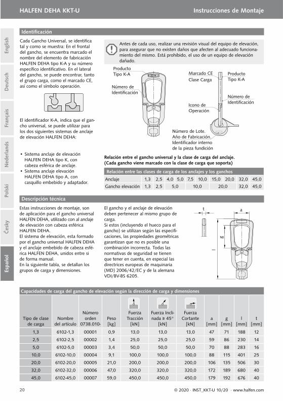
Cada Gancho Universal, se identifi ca tal y como se muestra: En el frontal del gancho, se encuentra marcado el nombre del elemento de fabricación HALFEN DEHA tipo K-A y su número específi co identifi cativo. En el lateral del gancho, se puede encontrar, tanto el grupo carga, como el marcado CE, así como el símbolo operación.
El identifi cador K-A, indica que el gan-cho universal, se puede utilizar para los dos siguientes sistemas de anclaje de elevación HALFEN DEHA:
• Sistema anclaje de elevación HALFEN DEHA tipo K, con cabeza esférica de anclaje.• Sistema anclaje elevación HALFEN DEHA tipo A, con casquillo embebido y adaptador.
Icono de Operación
Número de Lote.Año de Fabricación.Identifi cador interno de la pieza fundición
Clase CargaMarcado CE
ProductoTipo K-A Producto
Tipo K-A
Número de Identifi cación
Número de Identifi cación
Antes de cada uso, realizar una revisión visual del equipo de elevación, para asegurar que no existen daños que afecten al adecuado funciona-miento del mismo. Está prohibido, el uso de un equipo de elevación dañado.
Relación entre el gancho universal y la clase de carga del anclaje.(Cada gancho viene marcado con la clase de carga que soporta)
Relación entre las clases de carga de los anclajes y los ganchos
Anclaje 1,3 2,5 4,0 5,0 7,5 10,0 15,0 20,0 32,0 45,0
Gancho elevación 1,3 2,5 5,0 10,0 20,0 32,0 45,0
l
g
at
Descripción técnica
Estas instrucciones de montaje, son de aplicación para el gancho universal HALFEN DEHA, utilizado con al anclaje de elevación con cabeza esférica HALFEN DEHA. El sistema de elevación, esta formado por el gancho universal HALFEN DEHA y el anclaje embebido de cabeza esfé-rica HALFEN DEHA, unidos entre si de forma manual.En la siguiente tabla, se detallan los grupos de carga y dimensiones.
El gancho y el anclaje de elevación deben pertenecer al mismo grupo de carga.Si estos (incluyendo el hueco para el gancho) se utilizan según las especifi -caciones, las propiedades geométricas garantizan que no es posible una combinación incorrecta. Todas las normativas de seguridad se tienen que tener en cuenta, en especial las directrices europeas de maquinaria (MD) 2006/42/EC y de la alemana VDI/BV-BS 6205.
Capacidades de carga del gancho de elevación según la dirección de carga y dimensiones
Tipo de clase de carga
Nombre del artículo
Número orden
0738.010-Peso[kg]
Fuerza Tracción
[kN]
Fuerza Incli-nada ≥ 45°
[kN]
Fuerza Cortante
[kN]a
[mm]g
[mm]l
[mm]t
[mm]
1,3 6102-1,3 00001 0,9 13,0 13,0 13,0 47 71 188 12
2,5 6102-2,5 00002 1,4 25,0 25,0 25,0 59 86 230 14
5,0 6102-5,0 00003 3,4 50,0 50,0 50,0 70 88 283 16
10,0 6102-10,0 00004 9,1 100,0 100,0 100,0 88 115 401 25
20,0 6102-20,0 00005 21,0 200,0 200,0 200,0 106 135 506 30
32,0 6102-32,0 00006 47,0 320,0 320,0 320,0 172 189 680 40
45,0 6102-45,0 00007 59,0 450,0 450,0 450,0 179 192 676 40
21© 2020 · INST_KKT-U 10/20 · www.halfen.com
HALFEN DEHA KKT-U Instrucciones de Montaje
Deu
tsch
Engl
ish
Fran
çais
Ned
erla
nds
Pols
kiEs
paño
lČ
esky
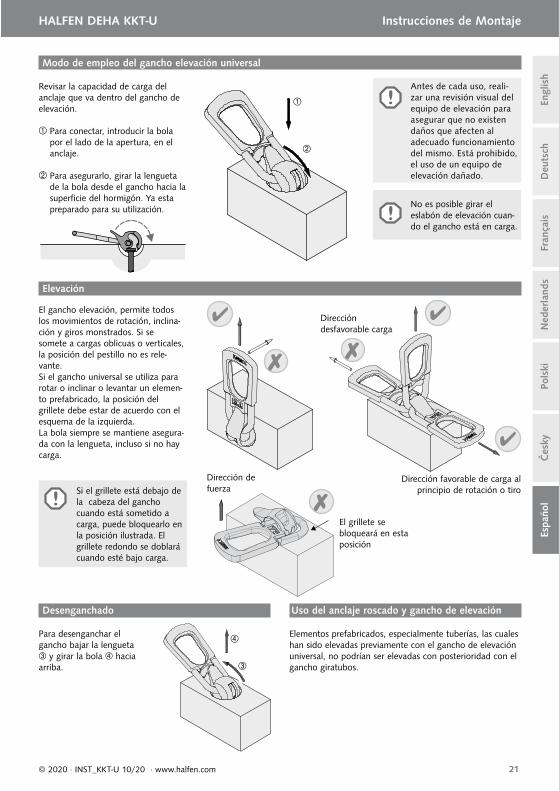
El gancho elevación, permite todos los movimientos de rotación, inclina-ción y giros monstrados. Si se somete a cargas oblicuas o verticales, la posición del pestillo no es rele-vante.Si el gancho universal se utiliza para rotar o inclinar o levantar un elemen-to prefabricado, la posición delgrillete debe estar de acuerdo con el esquema de la izquierda.La bola siempre se mantiene asegura-da con la lengueta, incluso si no hay carga.
Para desenganchar el gancho bajar la lengueta
y girar la bola hacia arriba.
Dirección desfavorable carga
Dirección favorable de carga al principio de rotación o tiro
Uso del anclaje roscado y gancho de elevaciónDesenganchado
Modo de empleo del gancho elevación universal
Elevación
No es posible girar el eslabón de elevación cuan-do el gancho está en carga.
Elementos prefabricados, especialmente tuberías, las cuales han sido elevadas previamente con el gancho de elevación universal, no podrían ser elevadas con posterioridad con el gancho giratubos.
Revisar la capacidad de carga del anclaje que va dentro del gancho de elevación.
Para conectar, introducir la bola por el lado de la apertura, en el anclaje.
Para asegurarlo, girar la lengueta de la bola desde el gancho hacia la superfi cie del hormigón. Ya esta preparado para su utilización.
Si el grillete está debajo de la cabeza del gancho cuando está sometido a carga, puede bloquearlo en la posición ilustrada. El grillete redondo se doblará cuando esté bajo carga.
El grillete se bloqueará en esta posición
Dirección defuerza
Antes de cada uso, reali-zar una revisión visual del equipo de elevación para asegurar que no existen daños que afecten al adecuado funcionamiento del mismo. Está prohibido, el uso de un equipo de elevación dañado.
22 © 2020 · INST_KKT-U 10/20 · www.halfen.com
HALFEN DEHA KKT-U Instrucciones de MontajeD
euts
chEn
glis
hFr
ança
isN
eder
land
sPo
lski
Espa
ñol
Čes
ky
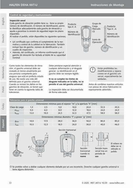
Inspección anualCada gancho de elevación pedido tiene su, tiene su propio número de identifi cación. El número de identifi cación, permi-te identifi car adecuadamente cada gancho de elevación y ayuda a garantizar la revisión de seguridad según los plazos requeridos.Al realizar el pedido, están disponibles las siguientes opciones; • Un certifi cado que confi rma el cumplimiento de la nor-
mativa y control de la calidad en la fabricación. También incluye tipo de gancho, número de identifi cación y un cuadro de inspección.
• Además, del certifi cado, un informe confi rmando que el gancho de elevación fue testado al doble de su capacidad nominal.
Control de seguridad y mantenimiento
Icono de Operación
Producto Tipo K - A
Grupo de CargaMarcadoCE
Productotipo K -A
Número de Identifi cación Número de
Identifi cación
Como todos los elementos de eleva-ción, el gancho universal debe ser revisado al menos anualmente por una persona competente para asegurar que está en prefecto estado de uso. No existe una vida útil defi nida para el gancho universal.Cuando se revisan los daños en los ganchos de elevación, se tienen que tener en cuenta la siguiente tabla de tolerancias.
Debe prestarse especial atención a cualquier deformación y al desgaste general. La identifi cación en el gancho debe ser siempre legible.
Si no se cumplen los límites de desgaste indicados en la tabla, no se permite el uso del gancho universal.
La inspección debe ser documentada de forma adecuada.
Tolerancias para el gancho universal
Dimensiones mínimas para el espesor ”m” y la apertura ”h” [mm]
Clase de carga 1,3 2,5 5,0 10,0 20,0 32,0 45,0mmin 5,5 6,0 8,0 12,0 18,0 24,0 24,0hmax 13,0 18,0 24,5 32,5 47,5 58,0 58,0
Dimensiones mínimas diametro ”f” y grosor ”g” [mm]
gmin 14,0 17,5 28,0 36,0 56,0 80,0 85,0
fmin 10,5 12,5 18,5 26,0 36,0 40,0 46,0
Se prohíbe volver a doblar cualquier elemento dañado por un uso incorrecto. Deseche cualquier gancho universal si tiene alguna distorsión.
h
m
f
El relieve no debe ser ni retirado ni pulido.
g
Sección transversal cuando es nuevo
g min
Sección trans-versal tras un periodo de uso
Sección transversal
Están prohibidas las modifi caciones y repara-ciones en el gancho uni-versal, especialmente las soldadas.
Antes de combinar nuestros artículoscon piezas de otros fabricantes es expresamente advertido.
For more information on the products featured here, please contact Leviat:
Notes regarding this catalogue
© Protected by copyright. The construction applications and details provided in this publication are
indicative only. In every case, project working details should be entrusted to appropriately qualified
and experienced persons. Whilst every care has been exercised in the preparation of this publication
to ensure that any advice, recommendations or information is accurate, no liability or responsibility
of any kind is accepted by Leviat for inaccuracies or printing errors. Technical and design changes
are reserved. With a policy of continuous product development, Leviat reserves the right to modify
product design and specification at any time.
Leviat.com
For information on certified management systems and standards, see www.halfen.com
AustraliaLeviat
98 Kurrajong Avenue,
Mount Druitt Sydney, NSW 2770
Tel: +61 - 2 8808 3100
Email: [email protected]
AustriaLeviat
Leonard-Bernstein-Str. 10
Saturn Tower, 1220 Wien
Tel: +43 - 1 - 259 6770
Email: [email protected]
Belgium Leviat
Borkelstraat 131
2900 Schoten
Tel: +32 - 3 - 658 07 20
Email: [email protected]
China Leviat
Room 601 Tower D,
Vantone Centre
No. A6 Chao Yang Men Wai Street
Chaoyang District
Beijing · P.R. China 100020
Tel: +86 - 10 5907 3200
Email: [email protected]
Czech Republic Leviat
Business Center Šafránkova
Šafránkova 1238/1
155 00 Praha 5
Tel: +420 - 311 - 690 060
Email: [email protected]
FinlandLeviat
Vädursgatan 5
412 50 Göteborg / Sweden
Tel: +358 (0)10 6338781
Email: [email protected]
France Leviat
18, rue Goubet
75019 Paris
Tel: +33 - 1 - 44 52 31 00
Email: [email protected]
Germany Leviat
Liebigstrasse 14
40764 Langenfeld
Tel: +49 - 2173 - 970 - 0
Email: [email protected]
IndiaLeviat
309, 3rd Floor, Orion Business Park
Ghodbunder Road, Kapurbawdi,
Thane West, Thane,
Maharashtra 400607
Tel: +91 - 22 2589 2032
Email: [email protected]
Italy Leviat
Via F.lli Bronzetti 28
24124 Bergamo
Tel: +39 - 035 - 0760711
Email: [email protected]
MalaysiaLeviat
28 Jalan Anggerik Mokara 31/59
Kota Kemuning,
40460 Shah Alam Selangor
Tel: +603 - 5122 4182
Email: [email protected]
Netherlands Leviat
Oostermaat 3
7623 CS Borne
Tel: +31 - 74 - 267 14 49
Email: [email protected]
New ZealandLeviat
2/19 Nuttall Drive, Hillsborough,
Christchurch 8022
Tel: +64 - 3 376 5205
Email: [email protected]
Norway Leviat
Vestre Svanholmen 5
4313 Sandnes
Tel: +47 - 51 82 34 00
Email: [email protected]
Philippines Leviat
2933 Regus, Joy Nostalg,
ADB Avenue, Ortigas Center
Pasig City
Tel: +63 - 2 7957 6381
Email: [email protected]
Poland Leviat
Ul. Obornicka 287
60-691 Poznań
Tel: +48 - 61 - 622 14 14
Email: [email protected]
SingaporeLeviat
14 Benoi Crescent
Singapore 629977
Tel: +65 - 6266 6802
Email: [email protected]
Spain Leviat
Polígono Industrial Santa Ana
c/ Ignacio Zuloaga, 20
28522 Rivas-Vaciamadrid
Tel: +34 - 91 632 18 40
Email: [email protected]
Sweden Leviat
Vädursgatan 5
412 50 Göteborg
Tel: +46 - 31 - 98 58 00
Email: [email protected]
Switzerland Leviat
Hertistrasse 25
8304 Wallisellen
Tel: +41 - 44 - 849 78 78
Email: [email protected]
United Kingdom Leviat
A1/A2 Portland Close
Houghton Regis LU5 5AW
Tel: +44 - 1582 - 470 300
Email: [email protected]
United States of America Leviat
6467 S Falkenburg Rd.
Riverview, FL 33578
Tel: (800) 423-9140
Email: [email protected]
For countries not listedEmail: [email protected]
Halfen.com
Imagine. Model. Make. Leviat.com
© 2
02
0
U-4
22
– 1
0/2
0
PD
F 1
1/2
0
![E } u o } u u v / } u u v Z } µ ] Z u ] vrevit.downloads.autodesk.com/download/2018RVT_RTM/... · W u µ o u v ] WW u } o ] o/ z^ dd/E'^ z^hE E ^, Kt^^ dd/E'^^h ' EW u](https://static.fdocuments.fr/doc/165x107/5e2fab23a3ddad4b8a28eaa1/e-u-o-u-u-v-u-u-v-z-z-u-w-u-o-u-v-ww-u-o-o-z-dde.jpg)