Einbauanweisung D Elektrischer Zubehörsatz Installation … · · 2015-09-18Fahrzeuge mit...
80
Einbauanweisung Elektrischer Zubehörsatz 2-14 Installation Instructions Electrical Accessories Set 15-27 Instructions de montage Jeu d’accessoires électriques 28-40 Inbouwhandleiding Elektrisch Toebehoorpakket 41-53 Istruzioni di montaggio Kit elettrico per accessori 54-66 Instrucciones de montaje Juego de accesorios eléctricos 67-79 D GB F NL I E 313 116 391 103 - 002
-
Upload
nguyentuyen -
Category
Documents
-
view
219 -
download
1
Transcript of Einbauanweisung D Elektrischer Zubehörsatz Installation … · · 2015-09-18Fahrzeuge mit...
1
313 116 391 102 24/02
EinbauanweisungElektrischer Zubehörsatz2-14
Installation InstructionsElectrical Accessories Set15-27
Instructions de montageJeu d’accessoires électriques28-40
InbouwhandleidingElektrisch Toebehoorpakket41-53
Istruzioni di montaggioKit elettrico per accessori54-66
Instrucciones de montajeJuego de accesorios eléctricos67-79
D
GB
F
NL
I
E
313 116 391 103 - 002
fkirakos
Rechteck
fkirakos
Stempel
2
Elektrischer Zubehörsatz
Westfalia-Bestell-Nr.: 313 116 300 113/123/133
Verwendungsbereich: Mercedes-Benz Typ 210 alle ModelleLimousine und T-LimousineMercedes-Benz Typ 208 alle Modelle
Allgemeine Hinweise:
Vor Arbeitsbeginn bitte die Einbauanweisung durchlesen.
Gebohrte Löcher müssen entgratet und anschließend mit Zinkstaubfarbe gestrichen werden.
Die Installation des Elektrosatzes darf nur von Fachpersonal bei abgeschlossener Batteriemöglichst mit Hilfe eines Ruhestromerhaltungsgerät durchgeführt werden.
Alle Lötverbindungen sind mit einem Schrumpfschlauch zu isolieren.
Der Ausfall einer Blinkleuchte auch am Anhänger wird durch die Erhöhung derBlinkfrequenz angezeigt, dadurch ist keine zusätzliche Blinkkontrolle notwendig.
Beim Abschließen der Batterie können gespeicherte Daten verloren gehen!Bitte Hersteller Informationen beachten.
Dieser Leitungssatz ist mit einer Nebelschlußleuchtenabschaltung ausgerüstet.
Wichtig!
Bitte Änderungen für Typ 210 Limousine und T-Limousine ab 03/97 ab Seite 13 beachten.
Zusatzinformation zum Einbau in den Typ Coupe 208 ab Seite 14.
Bei Verwendung eines 7 poligen Adapters ist dieser nach Beendigung der Anhängerfahrtwieder aus der Steckdose zu entfernen.
D
313 116 391 103 - 002
fkirakos
Rechteck
fkirakos
Stempel
3
Mercedes-Benz Typ 210, Limousine und T-Limousine
Stückliste:
– Anbauanleitung
– Leitungssatz Typ 210/208 mit vorkonfektioniertem Steckdoseneinsatz
– Befestigungsmaterial
– Steckdosengehäuse mit Mikroschalter
– Nebelschlußleuchten Abschaltrelais
– Arbeitsanweisung
Allgemeine Arbeiten:
– Kofferraumverkleidung links ........................... aus-, einbauen– Teppich in Kofferraumboden ........................... herausnehmen, einlegen– Fondsitzlehne und Sitzkissen ......................... aus-, einbauen– Verkleidung Einstieg links hinten / vorne ........ aus-, einbauen– untere Verkleidung B-Säule links ................... aus-, einbauen– Kabelkanal links ............................................. öffnen-, schließen– Lichtmodul ...................................................... aus-, einbauen
313 116 391 103 - 002
4
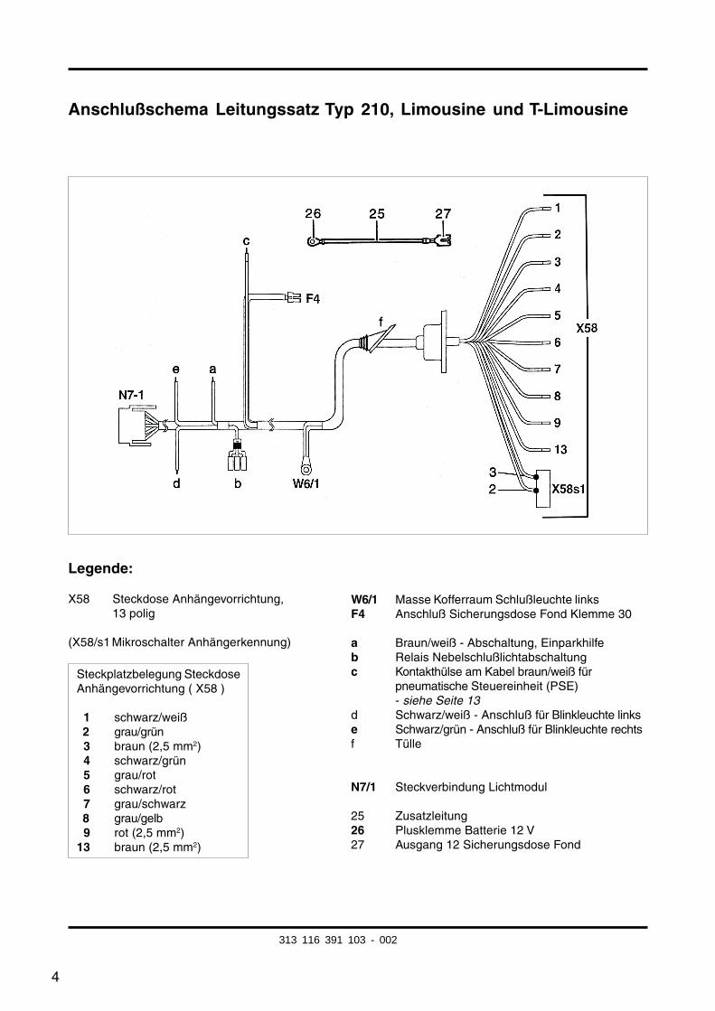
Anschlußschema Leitungssatz Typ 210, Limousine und T-Limousine
Legende:
X58 Steckdose Anhängevorrichtung,13 polig
(X58/s1 Mikroschalter Anhängerkennung)
W6/1 Masse Kofferraum Schlußleuchte linksF4 Anschluß Sicherungsdose Fond Klemme 30
a Braun/weiß - Abschaltung, Einparkhilfeb Relais Nebelschlußlichtabschaltungc Kontakthülse am Kabel braun/weiß für
pneumatische Steuereinheit (PSE)- siehe Seite 13
d Schwarz/weiß - Anschluß für Blinkleuchte linkse Schwarz/grün - Anschluß für Blinkleuchte rechtsf Tülle
N7/1 Steckverbindung Lichtmodul
25 Zusatzleitung26 Plusklemme Batterie 12 V27 Ausgang 12 Sicherungsdose Fond
Steckplatzbelegung SteckdoseAnhängevorrichtung ( X58 )
01 schwarz/weiß02 grau/grün03 braun (2,5 mm2)04 schwarz/grün05 grau/rot06 schwarz/rot07 grau/schwarz08 grau/gelb09 rot (2,5 mm2)13 braun (2,5 mm2)
313 116 391 103 - 002
5
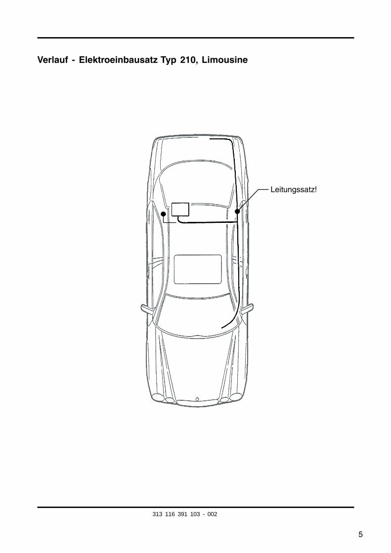
Verlauf - Elektroeinbausatz Typ 210, Limousine
Leitungssatz!
313 116 391 103 - 002
6
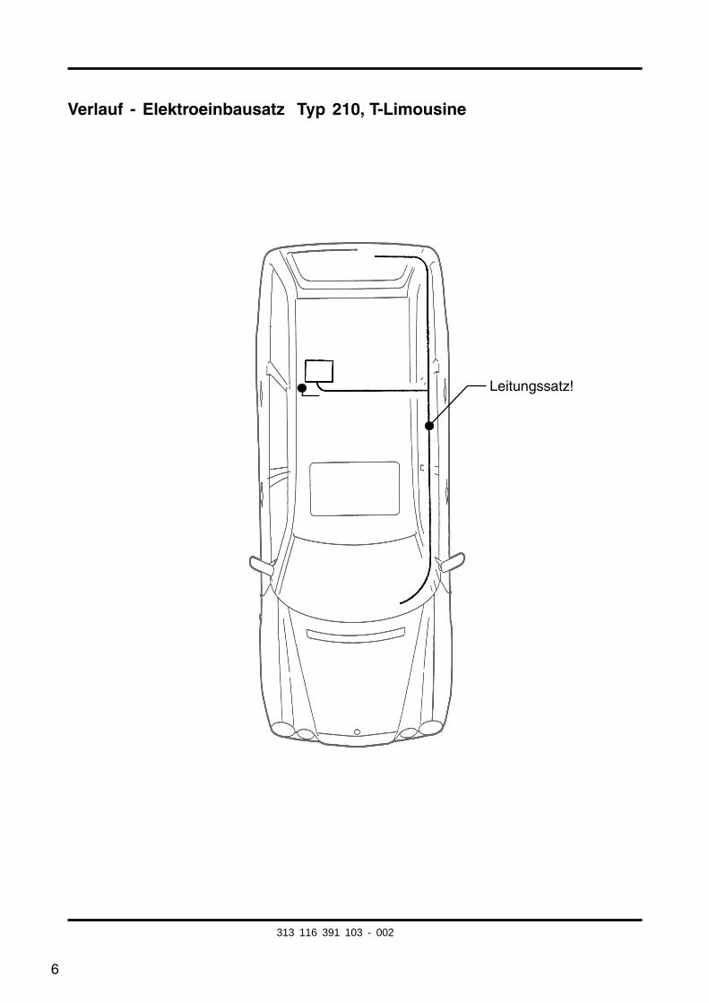
Verlauf - Elektroeinbausatz Typ 210, T-Limousine
Leitungssatz!
313 116 391 103 - 002
7
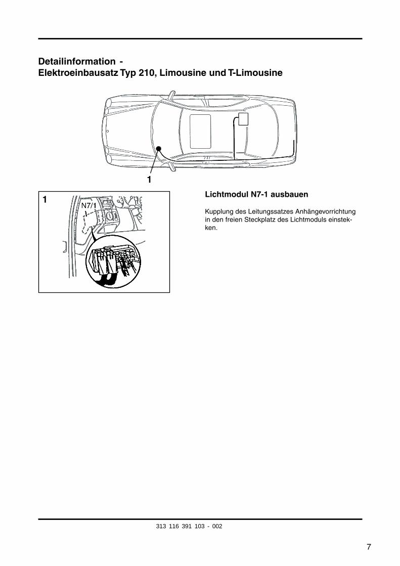
Detailinformation -Elektroeinbausatz Typ 210, Limousine und T-Limousine
Lichtmodul N7-1 ausbauen
Kupplung des Leitungssatzes Anhängevorrichtungin den freien Steckplatz des Lichtmoduls einstek-ken.
1
1
313 116 391 103 - 002
8
Detailinformation -Elektroeinbausatz Typ 210, Limousine und T-Limousine
2
3b
3a
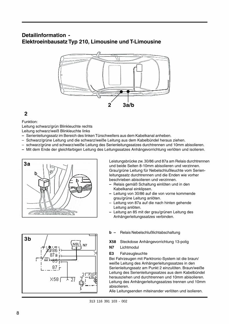
Funktion:Leitung schwarz/grün Blinkleuchte rechtsLeitung schwarz/weiß Blinkleuchte links– Serienleitungssatz im Bereich des linken Türschwellers aus dem Kabelkanal anheben.– Schwarz/grüne Leitung und die schwarz/weiße Leitung aus dem Kabelbündel heraus ziehen.– schwarz/grüne und schwarz/weiße Leitung des Serienleitungssatzes durchtrennen und 10mm abisolieren.– Mit dem Ende der gleichfarbigen Leitung des Leitungssatzes Anhängevorrichtung verlöten und isolieren.
Leistungsbrücke zw. 30/86 und 87a am Relais durchtrennenund beide Seiten 8-10mm abisolieren und verzinnen.Grau/grüne Leitung für Nebelschlußleuchte vom Serien-leitungssatz durchtrennen und die Enden wie vorherbeschrieben abisolieren und verzinnen.– Relais gemäß Schaltung einlöten und in den
Kabelkanal einklipsen.– Leitung von 30/86 auf die von vorne kommende
grau/grüne Leitung anlöten.– Leitung von 87a auf die nach hinten gehende
Leitung anlöten.– Leitung an 85 mit der grau/grünen Leitung des
Anhängerleitungssatzes verbinden.
b – Relais Nebelschlußlichtabschaltung
X58 Steckdose Anhängevorrichtung 13-polig
N7 Lichtmodul
E3 FahzeugleuchteBei Fahrzeugen mit Parktronic-System ist die braun/weiße Leitung des Anhängerleitungssatzes in denSerienleitungssatz am Punkt 2 einzulöten. Braun/weißeLeitung des Serienleitungssatzes aus dem Kabelbündelherausziehen und durchtrennen und 10mm abisolieren.Leitung des Anhängerleitungssatzes trennen und 10mmabisolieren.Alle Leitungsenden miteinander verlöten und isolieren.
2 3a/b
313 116 391 103 - 002
fkirakos
Rechteck
fkirakos
Stempel
9
5b
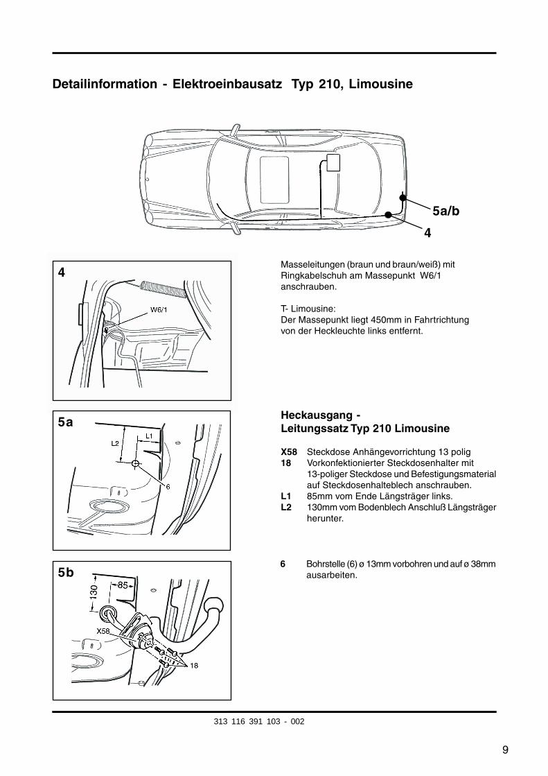
Detailinformation - Elektroeinbausatz Typ 210, Limousine
Masseleitungen (braun und braun/weiß) mitRingkabelschuh am Massepunkt W6/1anschrauben.
T- Limousine:Der Massepunkt liegt 450mm in Fahrtrichtungvon der Heckleuchte links entfernt.
4
5a/b
4
5a
6 Bohrstelle (6) ø 13mm vorbohren und auf ø 38mmausarbeiten.
Heckausgang -Leitungssatz Typ 210 Limousine
X58 Steckdose Anhängevorrichtung 13 polig18 Vorkonfektionierter Steckdosenhalter mit
13-poliger Steckdose und Befestigungsmaterialauf Steckdosenhalteblech anschrauben.
L1 85mm vom Ende Längsträger links.L2 130mm vom Bodenblech Anschluß Längsträger
herunter.
313 116 391 103 - 002
10
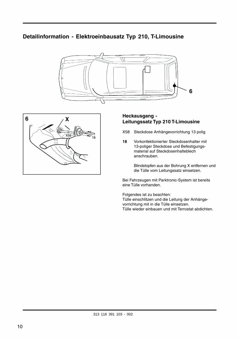
Detailinformation - Elektroeinbausatz Typ 210, T-Limousine
Heckausgang -Leitungssatz Typ 210 T-Limousine
X58 Steckdose Anhängevorrichtung 13 polig
18 Vorkonfektionierter Steckdosenhalter mit13-poliger Steckdose und Befestigungs-material auf Steckdosenhalteblechanschrauben.
Blindstopfen aus der Bohrung X entfernen unddie Tülle vom Leitungssatz einsetzen.
Bei Fahrzeugen mit Parktronic-System ist bereitseine Tülle vorhanden.
Folgendes ist zu beachten:Tülle einschlitzen und die Leitung der Anhänge-vorrichtung mit in die Tülle einsetzen.Tülle wieder einbauen und mit Terrostat abdichten.
6
6 X
313 116 391 103 - 002
11
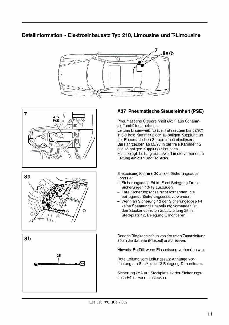
Detailinformation - Elektroeinbausatz Typ 210, Limousine und T-Limousine
A37 Pneumatische Steuereinheit (PSE)
Pneumatische Steuereinheit (A37) aus Schaum-stoffumhüllung nehmen.Leitung braun/weiß (c) (bei Fahrzeugen bis 02/97)in die freie Kammer 2 der 12-poligen Kupplung ander Pneumatischen Steuereinheit einclipsen.Bei Fahrzeugen ab 03/97 in die freie Kammer 15der 18-poligen Kupplung einclipsen.Falls belegt: Leitung braun/weiß in die vorhandeneLeitung einlöten und isolieren.
7 8a/b
Einspeisung Klemme 30 an der SicherungsdoseFond F4:– Sicherungsdose F4 im Fond Belegung für die
Sicherungen 10-18 ausbauen.– Falls Sicherungsdose nicht vorhanden, die
beiliegende Sicherungsdose verwenden.– Wenn an Sicherung 12 der Sicherungsdose F4
keine Spannungseinspeisung vorhanden ist,den Stecker der roten Zusatzleitung 25 inSteckplatz 12, Belegung E montieren.
Danach Ringkabelschuh von der roten Zusatzleitung25 an die Batterie (Pluspol) anschließen.
Hinweis: Entfällt wenn Einspeisung vorhanden war.
Rote Leitung vom Leitungssatz Anhängervor-richtung am Steckplatz 12 Belegung D montieren.
Sicherung 25A auf Steckplatz 12 der Sicherungs-dose F4 im Fond einstecken.
7
8b
8a
313 116 391 103 - 002
12
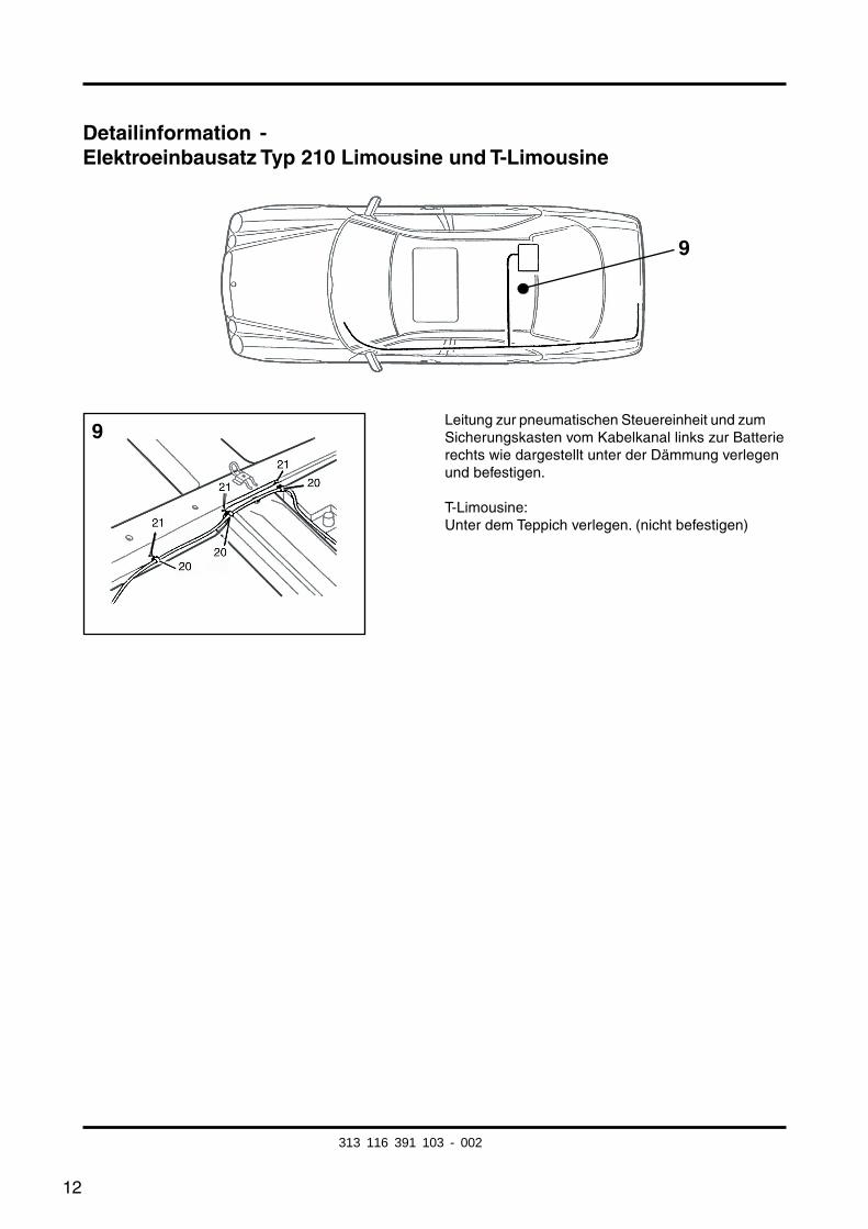
Detailinformation -Elektroeinbausatz Typ 210 Limousine und T-Limousine
Leitung zur pneumatischen Steuereinheit und zumSicherungskasten vom Kabelkanal links zur Batterierechts wie dargestellt unter der Dämmung verlegenund befestigen.
T-Limousine:Unter dem Teppich verlegen. (nicht befestigen)
9
9
313 116 391 103 - 002
13
Änderung Typ 210 ab 3/97:
Erkennungsmerkmal:
– Bei Modellen ab 03/97 ist kein Schlüsselbarth zum Starten des Motors vorhanden.
Bild Nr.: 7:Leitung braun/weiß (c) in die freie Kammer 15 der 18-poligen Kupplung der Pneumati-schen Steuereinheit einclipsen.
Falls belegt:Leitung braun/weiß in die vorhandene Leitungsschlaufe braun/weiß einlöten und isolieren.
( Bei Fahrzeugen bis 02/97 die braun/weiße Leitung in die freie Kammer 2 der 12-poligenKupplung der Pneumatischen Steuereinheit einclipsen.)
313 116 391 103 - 002
14
Zusatzinformation zum Einbau in den Typ A/C 208:
Arbeitsschritte für den Typ 210 Limousine bis auf folgende Änderungenauch für den Typ A/C 208 übernehmen.
Änderungen:
Allgemeine Arbeiten:– Kofferraumverkleidung rechts......................... aus-, und einbauen
Seite 4 Verlauf Leitungssatz:Die Leitungsverlegung der Querverbindung zur PSE und zur Batterie findet an der Vorder-wand des Gepäckraumes statt. Dort sind die zu verlegenden Leitungen den bereits vor-handenen Kabelstrang beizufügen.Hierzu den Einbausatz an der Ausbindung der Leitungen rot 2,5mm2 und braun/weiß0,75mm2 ca. 1.500 mm weiter auftrennen und neu wickeln.
Bei Modellen A/C 208 Heckausgang direkt hinter dem Steckdosenhalter in der Reserve-radmulde ausarbeiten.Hinweis: Der Steckdosenhalter am Querträger der Anhängevorrichtung dient als Schablone.
Bild Nr. 7:Leitung braun/weiß in freie Kammer 15 der 18-poligenKupplung der PneumatischenSteuereinheit einclipsen.Falls belegt: Leitung braun/weiß in die vorhandene Leitungsschlaufe braun/weiß einlötenund isolieren.
Bildserie Nr. 8 :A 208:Einspeisung Klemme 30 an der Sicherungsdose F1 neben der Batterie hinten rechtsim Gepäckraum.
C 208:Rote Leitung zur Einspeisung Klemme 30 mit nach vorne verlegen zur Steckkupplung N7/1.
Der exakte Steckplatz der Leitung ist über die Belegung der Fondssicherungsdose in derAbdeckung zu erfahren.
Fahrzeuge mit Parktronic-System (PTS):Braun/weiße Leitung vom Mikroschalter zur braun/weißen Leitung Parktronic-System imBereich Fondtüre rechts verlegen und verbinden und weiter zur pneumatischen Steuerein-heit verlegen und dort in Kammer 15 aufkontaktieren.Anschließend Verbindungspunkte isolieren.
313 116 391 103 - 002
15
Installation Instructions
Electrical Accessories Set
Westfalia Order No.: 313 116 300 113/123/133
Application: Mercedes-Benz Typ 210, all modelsSaloon and Estate (T model)Mercedes-Benz Typ 208 all models
General Instructions:
Please read these Installation Instructions before starting work.
Drilled holes must be deburred and then coated with zinc-rich paint.
The electrical set may only be installed by expert personnel, with the battery disconnectedand, if possible, with the aid of a device for maintaining the closed-circuit current.
All soldered connections must be insulated with a heat-shrinkable sleeve.
Failure of a direction indicator lamp, on the trailer too, is indicated by an increased flashingfrequency. This means there is no need to actually check the indicators.
Data may be lost when the battery is disconnected!
Please refer to the information provided by the manufacturer.
This wiring harness is equipped with a rear fog light switch-off function.
Important!
Please note the changes starting on page 26 for the Type 210 saloon and estate (T)models as of 3/97.
Refer to page 27 for additional information on how to install the set in the Type C 208.
When a 7-pin adaptor is used, it must be disconnected from the socket after completion ofa journey with the trailer.
GB
313 116 391 103 - 002
fkirakos
Rechteck
fkirakos
Stempel
16
Mercedes-Benz Typ 210, Saloon and Estate (T)
Parts list:
– Mounting instructions
– Line set type 210/208 with ready-made socket holder
– Fixing materials
– Socket housing with microswitch
– Rear fog lamps cutoff relay
– Work instructions
General work:
– Luggage compartment trim, left ..................... removing, installing– Carpet on luggage compartment floor ........... removing, laying– Rear seat backrest and seat cushion ............. removing, installing– Rocker plate trim, rear left / front left .............. removing, installing– Lower trim of B pillar on left ........................... removing, installing– Wiring duct, left ............................................... opening, closing– Lights module ................................................. removing, installing
313 116 391 103 - 002
17
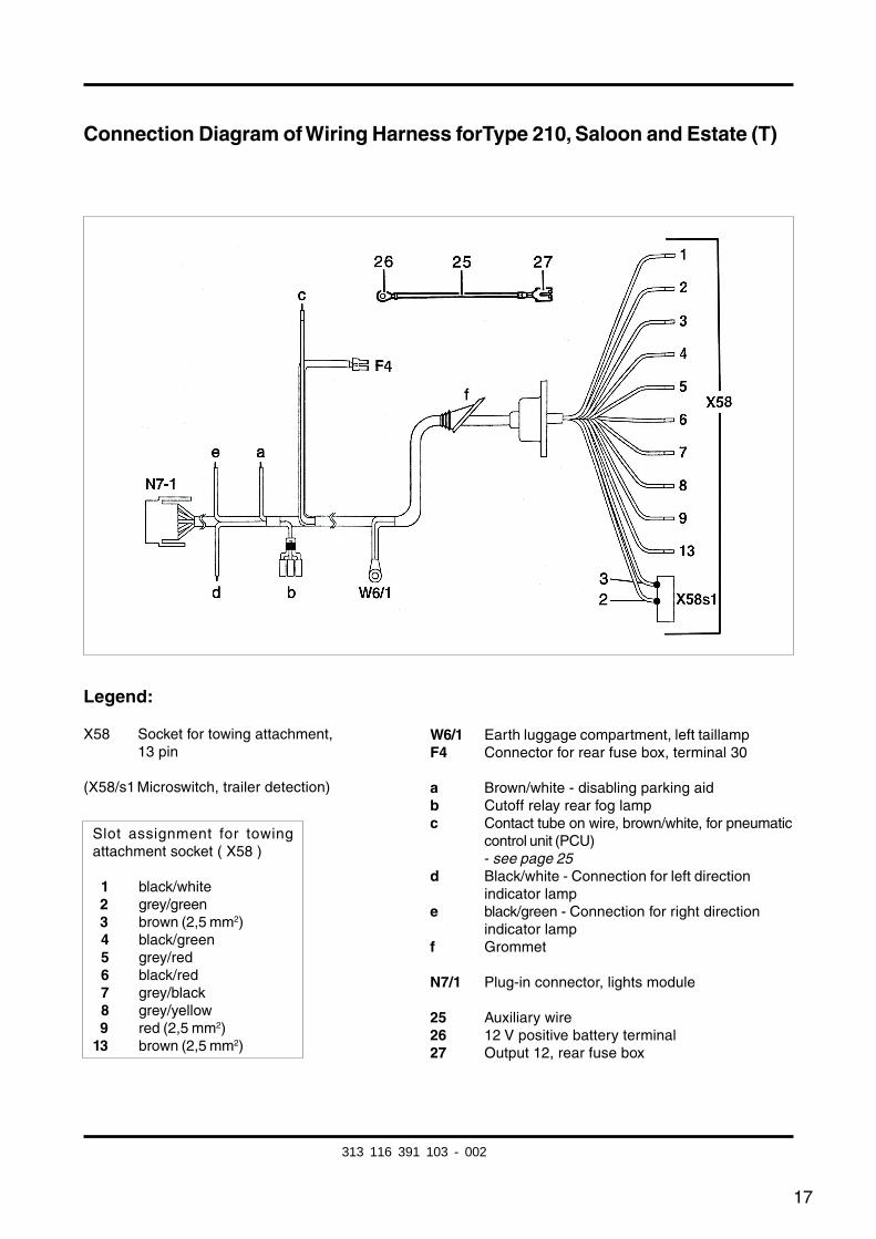
Connection Diagram of Wiring Harness forType 210, Saloon and Estate (T)
Legend:
X58 Socket for towing attachment,13 pin
(X58/s1 Microswitch, trailer detection)
W6/1 Earth luggage compartment, left taillampF4 Connector for rear fuse box, terminal 30
a Brown/white - disabling parking aidb Cutoff relay rear fog lampc Contact tube on wire, brown/white, for pneumatic
control unit (PCU)- see page 25
d Black/white - Connection for left directionindicator lamp
e black/green - Connection for right directionindicator lamp
f Grommet
N7/1 Plug-in connector, lights module
25 Auxiliary wire26 12 V positive battery terminal27 Output 12, rear fuse box
Slot assignment for towingattachment socket ( X58 )
01 black/white02 grey/green03 brown (2,5 mm2)04 black/green05 grey/red06 black/red07 grey/black08 grey/yellow09 red (2,5 mm2)13 brown (2,5 mm2)
313 116 391 103 - 002
18
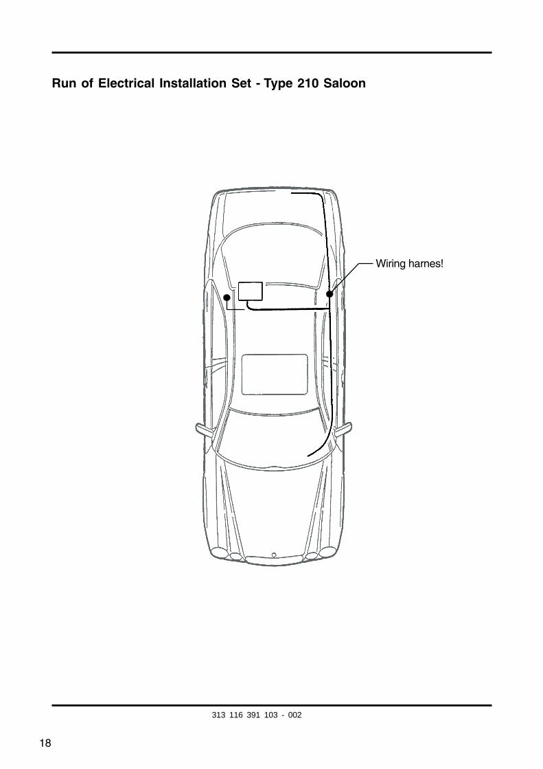
Run of Electrical Installation Set - Type 210 Saloon
Wiring harnes!
313 116 391 103 - 002
19
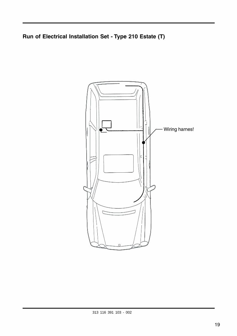
Run of Electrical Installation Set - Type 210 Estate (T)
Wiring harnes!
313 116 391 103 - 002

20
Detailed Information -Electrical Installation Set - Type 210 Saloon and Estate (T)
Remove lights module N7-1.
Insert the coupling of towing attachment wiringharness into the free slot of the lights module.
1
1
313 116 391 103 - 002
21
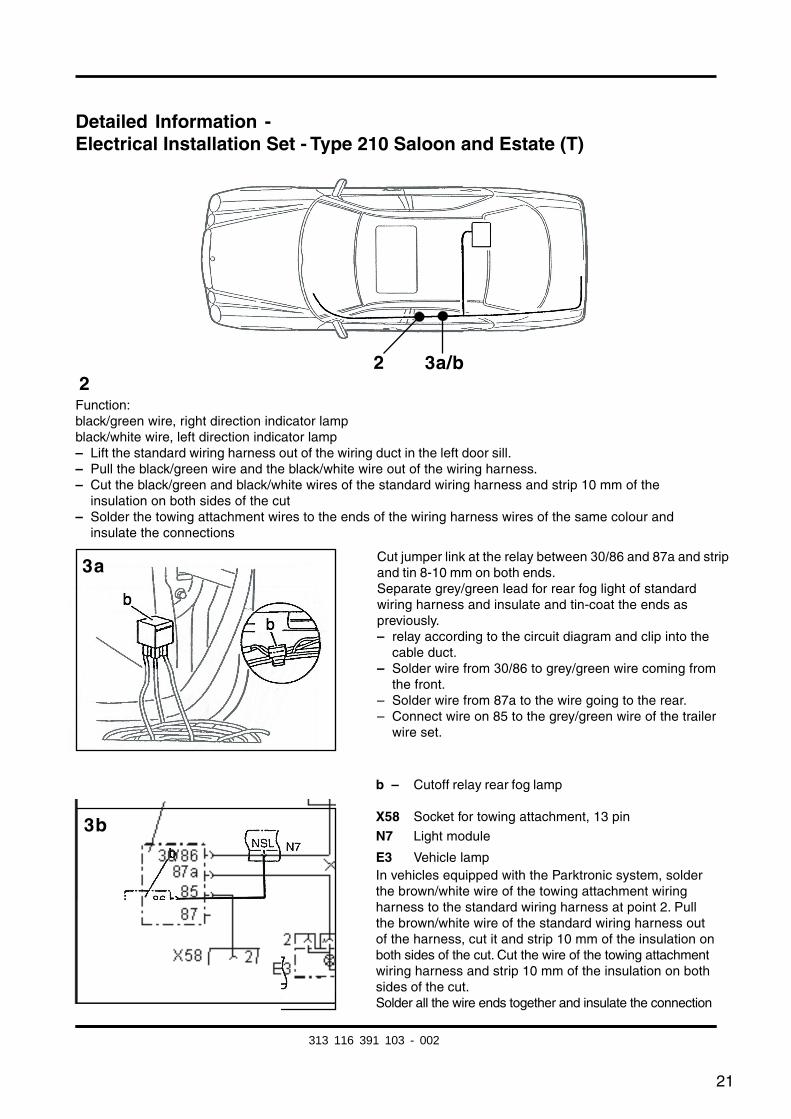
Detailed Information -Electrical Installation Set - Type 210 Saloon and Estate (T)
2
3b
3a
Function:black/green wire, right direction indicator lampblack/white wire, left direction indicator lamp– Lift the standard wiring harness out of the wiring duct in the left door sill.– Pull the black/green wire and the black/white wire out of the wiring harness.– Cut the black/green and black/white wires of the standard wiring harness and strip 10 mm of the
insulation on both sides of the cut– Solder the towing attachment wires to the ends of the wiring harness wires of the same colour and
insulate the connections
Cut jumper link at the relay between 30/86 and 87a and stripand tin 8-10 mm on both ends.Separate grey/green lead for rear fog light of standardwiring harness and insulate and tin-coat the ends aspreviously.– relay according to the circuit diagram and clip into the
cable duct.– Solder wire from 30/86 to grey/green wire coming from
the front.– Solder wire from 87a to the wire going to the rear.– Connect wire on 85 to the grey/green wire of the trailer
wire set.
b – Cutoff relay rear fog lamp
X58 Socket for towing attachment, 13 pin
N7 Light module
E3 Vehicle lampIn vehicles equipped with the Parktronic system, solderthe brown/white wire of the towing attachment wiringharness to the standard wiring harness at point 2. Pullthe brown/white wire of the standard wiring harness outof the harness, cut it and strip 10 mm of the insulation onboth sides of the cut. Cut the wire of the towing attachmentwiring harness and strip 10 mm of the insulation on bothsides of the cut.Solder all the wire ends together and insulate the connection
2 3a/b
313 116 391 103 - 002
fkirakos
Rechteck
fkirakos
Stempel
22
5b
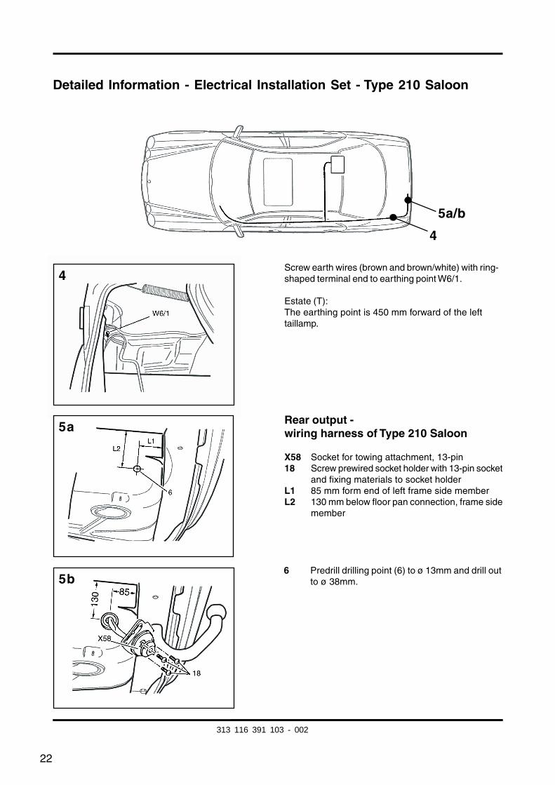
Detailed Information - Electrical Installation Set - Type 210 Saloon
Screw earth wires (brown and brown/white) with ring-shaped terminal end to earthing point W6/1.
Estate (T):The earthing point is 450 mm forward of the lefttaillamp.
4
5a/b
4
5a
6 Predrill drilling point (6) to ø 13mm and drill outto ø 38mm.
Rear output -wiring harness of Type 210 Saloon
X58 Socket for towing attachment, 13-pin18 Screw prewired socket holder with 13-pin socket
and fixing materials to socket holderL1 85 mm form end of left frame side memberL2 130 mm below floor pan connection, frame side
member
313 116 391 103 - 002
23
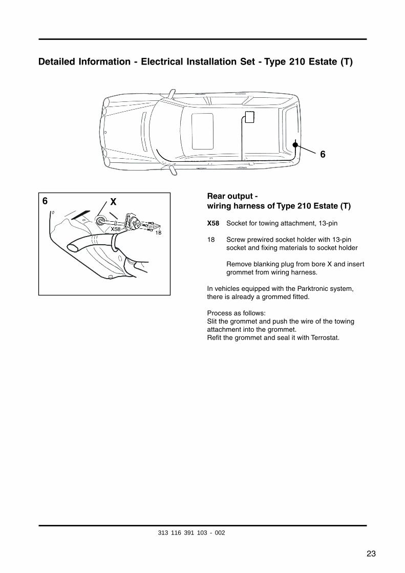
Detailed Information - Electrical Installation Set - Type 210 Estate (T)
Rear output -wiring harness of Type 210 Estate (T)
X58 Socket for towing attachment, 13-pin
18 Screw prewired socket holder with 13-pinsocket and fixing materials to socket holder
Remove blanking plug from bore X and insertgrommet from wiring harness.
In vehicles equipped with the Parktronic system,there is already a grommed fitted.
Process as follows:Slit the grommet and push the wire of the towingattachment into the grommet.Refit the grommet and seal it with Terrostat.
6
6 X
313 116 391 103 - 002
24
Detailed Information -Electrical Installation Set - Type 210 Saloon and Estate (T)
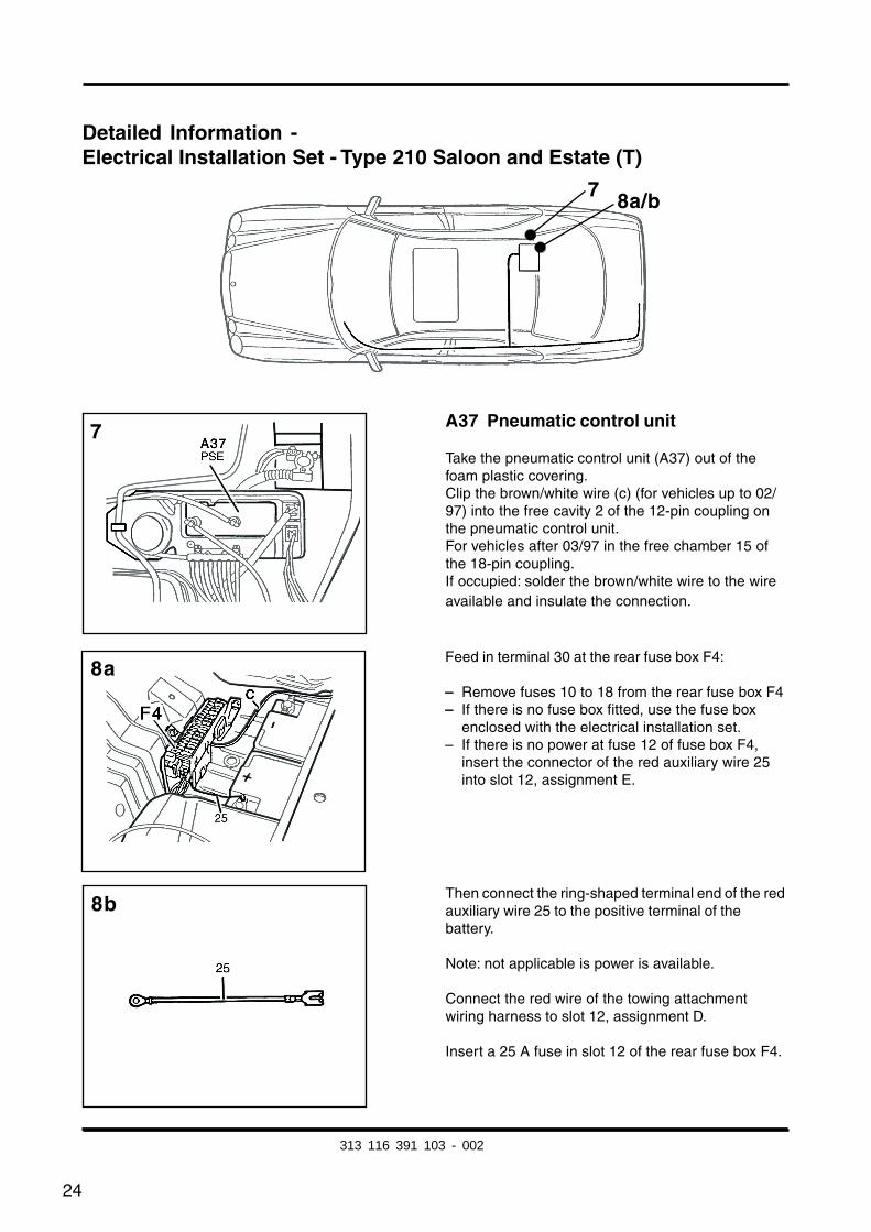
A37 Pneumatic control unit
Take the pneumatic control unit (A37) out of thefoam plastic covering.Clip the brown/white wire (c) (for vehicles up to 02/97) into the free cavity 2 of the 12-pin coupling onthe pneumatic control unit.For vehicles after 03/97 in the free chamber 15 ofthe 18-pin coupling.If occupied: solder the brown/white wire to the wireavailable and insulate the connection.
7 8a/b
Feed in terminal 30 at the rear fuse box F4:
– Remove fuses 10 to 18 from the rear fuse box F4– If there is no fuse box fitted, use the fuse box
enclosed with the electrical installation set.– If there is no power at fuse 12 of fuse box F4,
insert the connector of the red auxiliary wire 25into slot 12, assignment E.
Then connect the ring-shaped terminal end of the redauxiliary wire 25 to the positive terminal of thebattery.
Note: not applicable is power is available.
Connect the red wire of the towing attachmentwiring harness to slot 12, assignment D.
Insert a 25 A fuse in slot 12 of the rear fuse box F4.
7
8b
8a
313 116 391 103 - 002
25
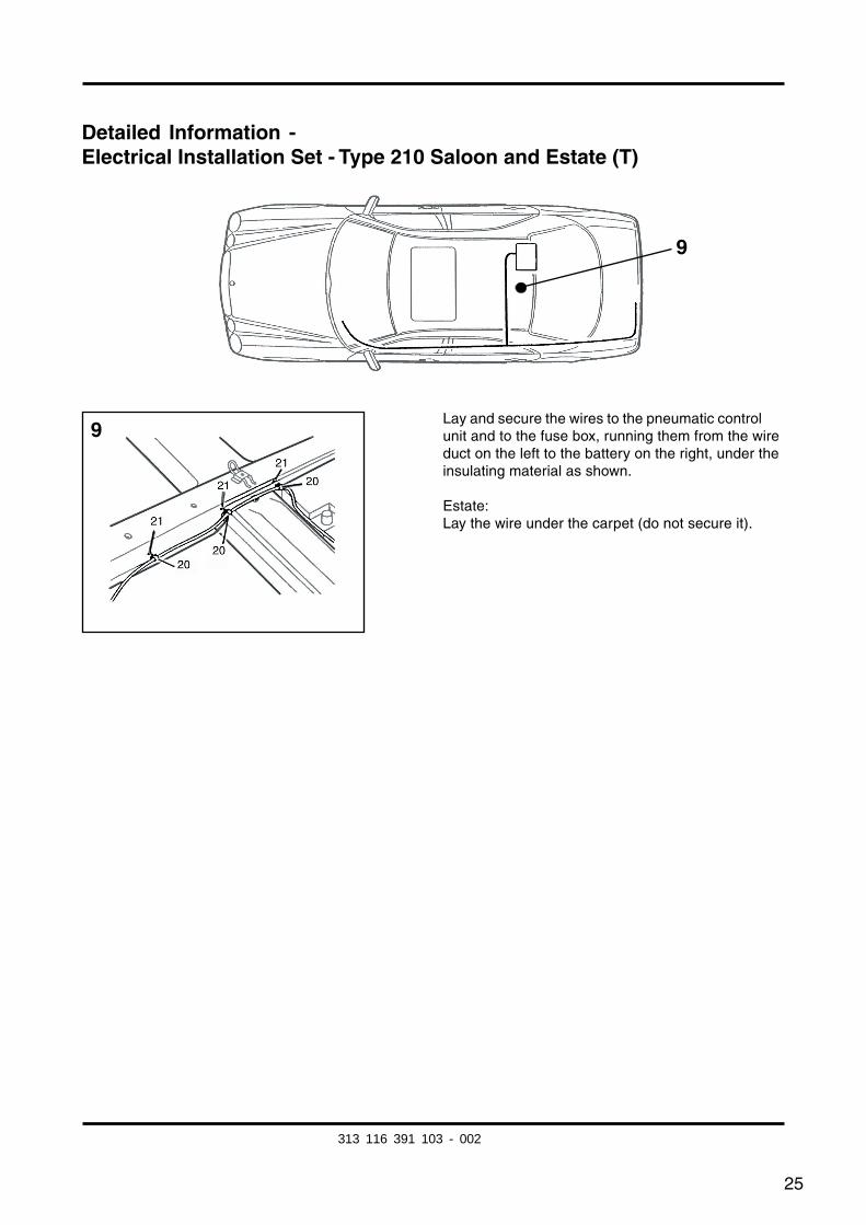
Detailed Information -Electrical Installation Set - Type 210 Saloon and Estate (T)
Lay and secure the wires to the pneumatic controlunit and to the fuse box, running them from the wireduct on the left to the battery on the right, under theinsulating material as shown.
Estate:Lay the wire under the carpet (do not secure it).
9
9
313 116 391 103 - 002
26
Changes to Type 210 as of 3/97:
Identifying feature:
– On models after 03/97 there is no key bit for starting the engine.
Fig.: 7:
Clip the brown/white wire into the free cavity 15 of the 18-pin coupling on the pneumaticcontrol unit.
If occupied:solder the brown/white wire into the existing brown/white wire loop and insulate theconnection.
(For vehicles up to 02/97 clip the brown/white wire into the free chamber 2 of the 12-pincoupling of the pneumatic control unit.)
313 116 391 103 - 002
27
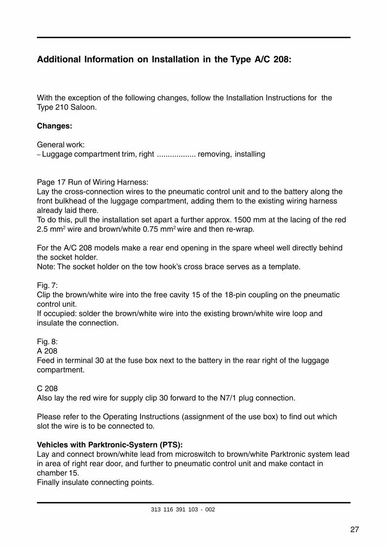
Additional Information on Installation in the Type A/C 208:
With the exception of the following changes, follow the Installation Instructions for theType 210 Saloon.
Changes:
General work:– Luggage compartment trim, right .................. removing, installing
Page 17 Run of Wiring Harness:Lay the cross-connection wires to the pneumatic control unit and to the battery along thefront bulkhead of the luggage compartment, adding them to the existing wiring harnessalready laid there.To do this, pull the installation set apart a further approx. 1500 mm at the lacing of the red2.5 mm2 wire and brown/white 0.75 mm2 wire and then re-wrap.
For the A/C 208 models make a rear end opening in the spare wheel well directly behindthe socket holder.Note: The socket holder on the tow hook’s cross brace serves as a template.
Fig. 7:Clip the brown/white wire into the free cavity 15 of the 18-pin coupling on the pneumaticcontrol unit.If occupied: solder the brown/white wire into the existing brown/white wire loop andinsulate the connection.
Fig. 8:A 208Feed in terminal 30 at the fuse box next to the battery in the rear right of the luggagecompartment.
C 208Also lay the red wire for supply clip 30 forward to the N7/1 plug connection.
Please refer to the Operating Instructions (assignment of the use box) to find out whichslot the wire is to be connected to.
Vehicles with Parktronic-Systern (PTS):Lay and connect brown/white lead from microswitch to brown/white Parktronic system leadin area of right rear door, and further to pneumatic control unit and make contact inchamber 15.Finally insulate connecting points.
313 116 391 103 - 002
28
Instructions de montage
Jeu d´accessoires électriques
Référence Westfalia-Bestell-Nr.: 313 116 300 113/123/133
Domaine d´utilisation: Mercedes-Benz Typ 210 tous les modèlesLimousine et T-LimousineMercedes-Benz Typ 208 tous les modèles
Informations générales:
Avant de commencer les travaux, veuillez lire les instructions de montage.
Il faut ébarber les trous perforés, puis peindre les arêtes à la peinture à base de poudrede zinc.
L’installation du jeu des pièces électriques doit être effectuée uniquement par desspécialistes après avoir débranché la batterie, le plus possible à l’aide d’un appareil demaintien du courant de repos.
Il faut isoler tous les points de brasage avec une gaine qui se rétracte.
La panne d’un clignotant, même sur la remorque, est indiquée par l’augmentation de lafréquence du clignotement; par conséquent, un contrôle supplémentaire du clignotementn’est pas nécessaire.
En débranchant la batterie, les données mises en mémoire risquent d’être perdues.Veuillez tenir compte des informations du fabricant.
Ce jeu de câbles est équipé d’un disjoncteur de feu antibrouillard arrière.
Important !
À partir de la page 39, veuillez observer les modifications pour je type 210 Limousine etLimousine T à partir de 3/97.
Informations supplémentaires pour le montage sur je type Coupé 208 é partir de la page 40.
Si on utilise un adaptateur à 7 pôles, il faut de nouveau enlever celui-ci de la prise decourant quand le remorquage est terminé.
F
313 116 391 103 - 002
fkirakos
Rechteck
fkirakos
Stempel
29
Mercedes-Benz type 210, Limousine et T-Limousine
Nomenclature:
– Instructions de montage
– Jeu de câbles de type 210/208 avec élément intérieur de prise préfabriqué
– Matériel de fixation
– Boîtier de prise de courant avec microcontacteur
– Relais de déconnexion des feux arrière de brouillard
– Instructions de travail
Travaux généraux:
– Habillage du coffre à bagages à gauche ........ Déposer, remonter– Tapis de fond du coffre à bagages ................. Retirer, poser– Dossier de la banquette et coussins .............. Déposer, remonter des sièges– Habillage bas de porte à gauche ................... Déposer, remonter à l’arrière /devant– Habillage inférieur de la colonne B ................ Déposer, remonter à gauche– Canal des câbles, à gauche ........................... Ouvrir, fermer– Module d’éclairage ......................................... Déposer, remonter
313 116 391 103 - 002
30
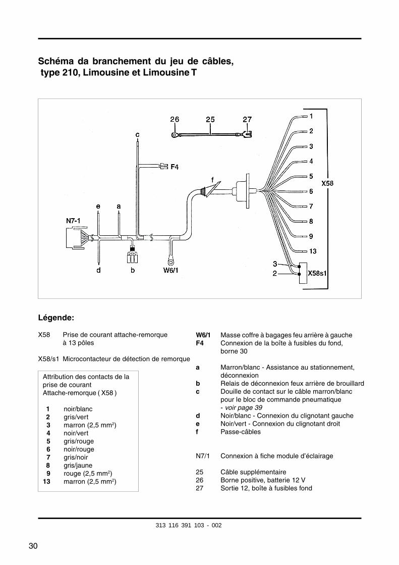
Schéma da branchement du jeu de câbles, type 210, Limousine et Limousine T
Légende:
X58 Prise de courant attache-remorqueà 13 pôles
X58/s1 Microcontacteur de détection de remorque
W6/1 Masse coffre à bagages feu arrière à gaucheF4 Connexion de la boîte à fusibles du fond,
borne 30
a Marron/blanc - Assistance au stationnement,déconnexion
b Relais de déconnexion feux arrière de brouillardc Douille de contact sur le câble marron/blanc
pour le bloc de commande pneumatique- voir page 39
d Noir/blanc - Connexion du clignotant gauchee Noir/vert - Connexion du clignotant droitf Passe-câbles
N7/1 Connexion à fiche module d’éclairage
25 Câble supplémentaire26 Borne positive, batterie 12 V27 Sortie 12, boîte à fusibles fond
Attribution des contacts de laprise de courantAttache-remorque ( X58 )
01 noir/blanc02 gris/vert03 marron (2,5 mm2)04 noir/vert05 gris/rouge06 noir/rouge07 gris/noir08 gris/jaune09 rouge (2,5 mm2)13 marron (2,5 mm2)
313 116 391 103 - 002
31
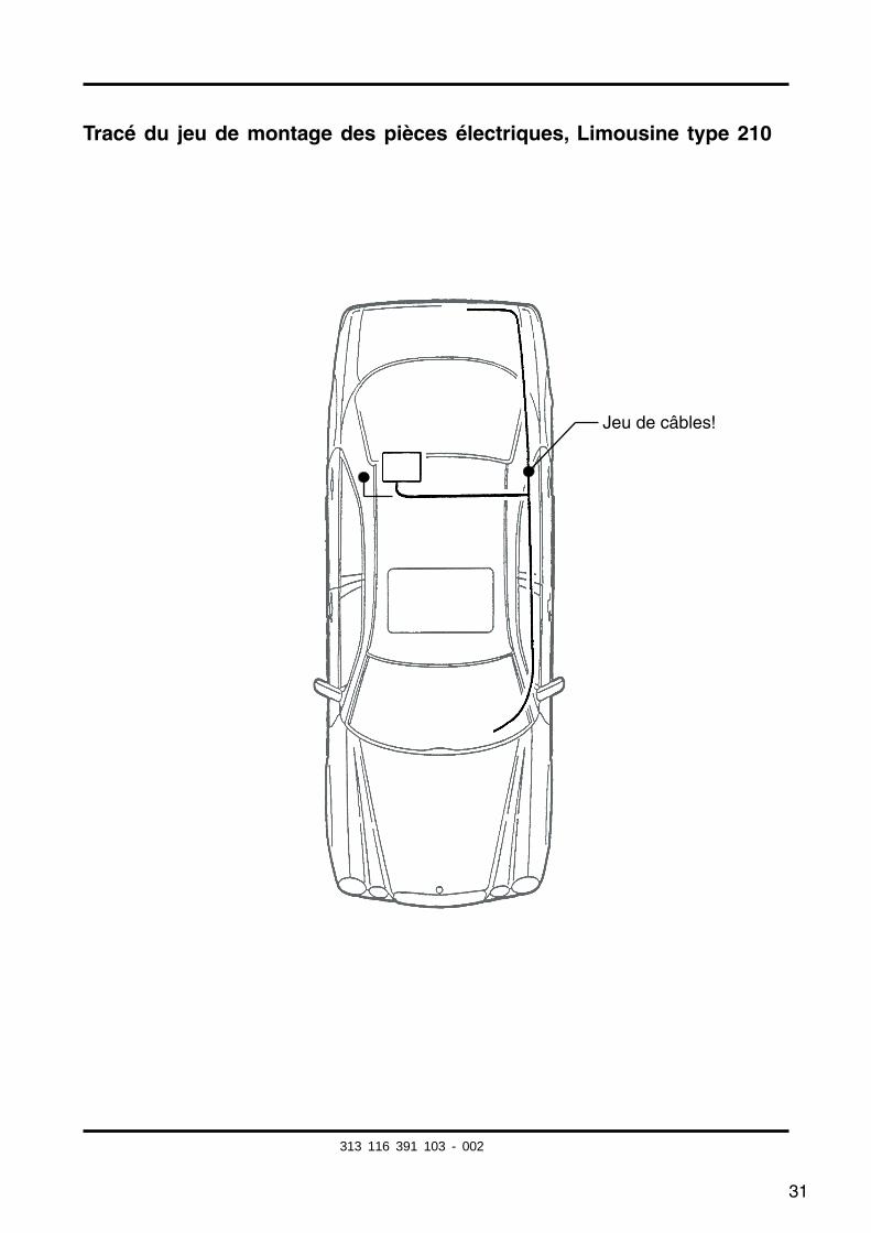
Tracé du jeu de montage des pièces électriques, Limousine type 210
Jeu de câbles!
313 116 391 103 - 002
32
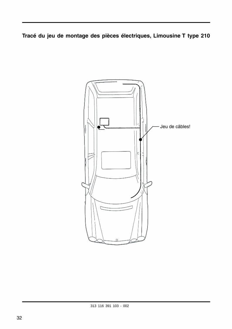
Tracé du jeu de montage des pièces électriques, Limousine T type 210
Jeu de câbles!
313 116 391 103 - 002

33
Informations détaillées -Jeu de montage des pièces électriques, Limousine et Limousine T type 210
Dépose du module d’éclairage N7-1
Enficher le coupleur du jeu de câbles de l’attache-remorque dans la connexion à fiche libre du moduled’éclairage.
1
1
313 116 391 103 - 002
34
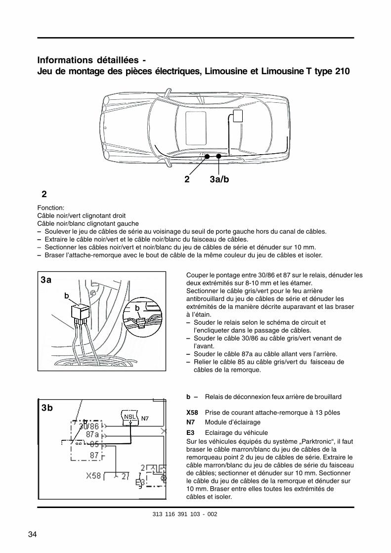
Informations détaillées -Jeu de montage des pièces électriques, Limousine et Limousine T type 210
2
3b
3a
Fonction:Câble noir/vert clignotant droitCâble noir/blanc clignotant gauche– Soulever le jeu de câbles de série au voisinage du seuil de porte gauche hors du canal de câbles.– Extraire le câble noir/vert et le câble noir/blanc du faisceau de câbles.– Sectionner les câbles noir/vert et noir/blanc du jeu de câbles de série et dénuder sur 10 mm.– Braser l’attache-remorque avec le bout de câble de la même couleur du jeu de câbles et isoler.
Couper le pontage entre 30/86 et 87 sur le relais, dénuder lesdeux extrémités sur 8-10 mm et les étamer.Sectionner le câble gris/vert pour le feu arrièreantibrouillard du jeu de câbles de série et dénuder lesextrémités de la manière décrite auparavant et las braserà I’étain.– Souder le relais selon le schéma de circuit et
l’encliqueter dans le passage de câbles.– Souder le câble 30/86 au câble gris/vert venant de l’avant.– Souder le câble 87a au câble allant vers l’arrière.– Relier le câble 85 au câble gris/vert du faisceau de
câbles de la remorque.
b – Relais de déconnexion feux arrière de brouillard
X58 Prise de courant attache-remorque à 13 pôles
N7 Module d’éclairage
E3 Eclairage du véhiculeSur les véhicules équipés du système „Parktronic“, il fautbraser le câble marron/blanc du jeu de câbles de laremorqueau point 2 du jeu de câbles de série. Extraire lecâble marron/blanc du jeu de câbles de série du faisceaude câbles; sectionner et dénuder sur 10 mm. Sectionnerle câble du jeu de câbles de la remorque et dénuder sur10 mm. Braser entre elles toutes les extrémités decâbles et isoler.
2 3a/b
313 116 391 103 - 002
fkirakos
Rechteck
fkirakos
Stempel
35
5b
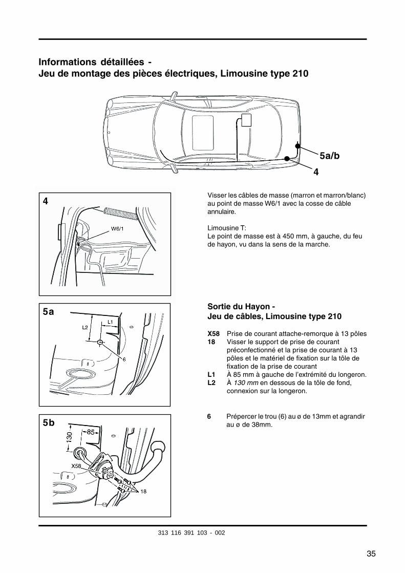
Informations détaillées -Jeu de montage des pièces électriques, Limousine type 210
Visser les câbles de masse (marron et marron/blanc)au point de masse W6/1 avec la cosse de câbleannulaire.
Limousine T:Le point de masse est à 450 mm, à gauche, du feude hayon, vu dans la sens de la marche.
4
5a/b
4
5a
6 Prépercer le trou (6) au ø de 13mm et agrandirau ø de 38mm.
Sortie du Hayon -Jeu de câbles, Limousine type 210
X58 Prise de courant attache-remorque à 13 pôles18 Visser le support de prise de courant
préconfectionné et la prise de courant à 13pôles et le matériel de fixation sur la tôle defixation de la prise de courant
L1 À 85 mm à gauche de l’extrémité du longeron.L2 À 130 mm en dessous de la tôle de fond,
connexion sur la longeron.
313 116 391 103 - 002
36
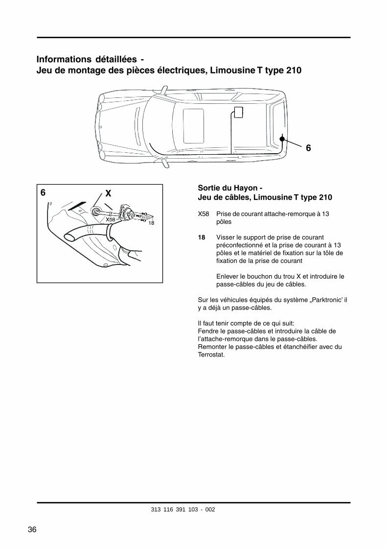
Informations détaillées -Jeu de montage des pièces électriques, Limousine T type 210
Sortie du Hayon -Jeu de câbles, Limousine T type 210
X58 Prise de courant attache-remorque à 13pôles
18 Visser le support de prise de courantpréconfectionné et la prise de courant à 13pôles et le matériel de fixation sur la tôle defixation de la prise de courant
Enlever le bouchon du trou X et introduire lepasse-câbles du jeu de câbles.
Sur les véhicules équipés du système „Parktronic’ ily a déjà un passe-câbles.
Il faut tenir compte de ce qui suit:Fendre le passe-câbles et introduire la câble del’attache-remorque dans le passe-câbles.Remonter le passe-câbles et étanchéifier avec duTerrostat.
6
6 X
313 116 391 103 - 002
37
Informations détaillées -Jeu de montage des pièces électriques, Limousine et Limousine T type 210
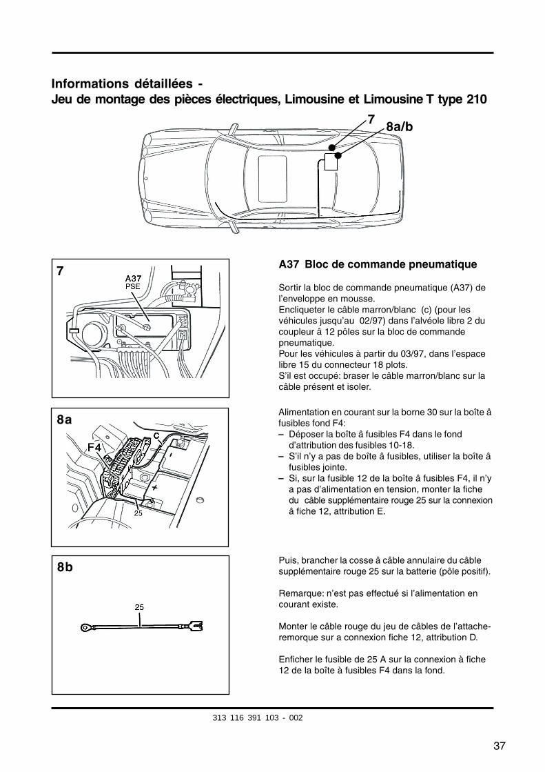
A37 Bloc de commande pneumatique
Sortir la bloc de commande pneumatique (A37) del’enveloppe en mousse.Encliqueter le câble marron/blanc (c) (pour lesvéhicules jusqu’au 02/97) dans l’alvéole libre 2 ducoupleur â 12 pôles sur la bloc de commandepneumatique.Pour les véhicules à partir du 03/97, dans l’espacelibre 15 du connecteur 18 plots.S’il est occupé: braser le câble marron/blanc sur lacâble présent et isoler.
7 8a/b
Alimentation en courant sur la borne 30 sur la boîte âfusibles fond F4:– Déposer la boîte â fusibles F4 dans le fond
d’attribution des fusibles 10-18.– S’il n’y a pas de boîte â fusibles, utiliser la boîte â
fusibles jointe.– Si, sur la fusible 12 de la boîte â fusibles F4, il n’y
a pas d’alimentation en tension, monter la fichedu câble supplémentaire rouge 25 sur la connexionâ fiche 12, attribution E.
Puis, brancher la cosse â câble annulaire du câblesupplémentaire rouge 25 sur la batterie (pôle positif).
Remarque: n’est pas effectué si l’alimentation encourant existe.
Monter le câble rouge du jeu de câbles de l’attache-remorque sur a connexion fiche 12, attribution D.
Enficher le fusible de 25 A sur la connexion à fiche12 de la boîte à fusibles F4 dans la fond.
7
8b
8a
313 116 391 103 - 002
38
Informations détaillées -Jeu de montage des pièces électriques, Limousine et Limousine T type 210
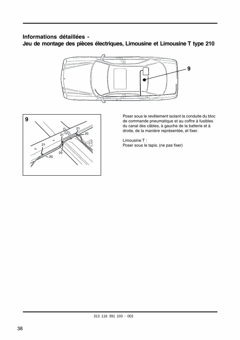
Poser sous le revêtement isolant la conduite du blocde commande pneumatique et au coffre à fusiblesdu canal des câbles, à gauche de la batterie et àdroite, de la manière représentée, et fixer.
Limousine T :Poser sous le tapis. (ne pas fixer)
9
9
313 116 391 103 - 002
39
Modification type 210 à partir de 3/97
Signe distinctif:
– La clé de contact des modèles jusqu’au 03/97 ne possède pas de panneton.
III. N° 7:
Encliqueter le câble marron/blanc dans l’alvéole 15 libre du coupleur à 18 pôles du bloc decommande pneumatique.
S’il est occupé:Braser le câble marron/blanc sur la boucle de câbles présente marron/blanc et isoler.
(Pour les véhicules jusqu’au 02/97, encliqueter le câble marron/blanc dans l’espace libre 2du connecteur 12 plots de l’unité de commande pneumatique.)
313 116 391 103 - 002
40
Information supplémentaire pour le montage sur le Coupé type 208:
Adopter les opérations de la Limousine type 210 à l’exception des modifications suivantesconcernant le Coupé A/C 208.
Modifications:
Travaux généraux:– Habillage du coffre à bagages à droite ......... Déposer et remonter
Page 30 Pose du jeu de câbles:La pose du câble de la liaison transversale au PSE et à la batterie a lieu sur la paroi avantdu coffre à bagages. Là, il faut ajouter au tronçon de câble déjà monté les câbles à poser.À cet effet, sectionner aussi le jeu de montage d’environ 1.500 mm sur la ligature descâbles rouges de 2,5mm2 et marron/blanc de 0,75mm2 et les enrouler de nouveau
Pour les modèles A/C 208, façonner la sortie arrière située sur la cavité de roue desecours, directement derrière la prise de courant.Remarque : Le support de prise de courant sur l’entretoise transversale du dispositifd’attelage fait office de gabarit.
Série d’illustrations N° 7:Encliqueter le câble marron/blanc dans l’alvéole libre 15 du coupleur à 18 pôles du bloc decommande pneumatique.S’il est occupé: braser le câble marron/blanc dans la boucle de câble présente marron/blanc et isoler.
Série d’illustrations N° 8:A 208:Alimentation en courant à la borne 30 sur la boîte à fusibles, à côté de la batterie, derrière‘a droite dans le coffre à bagages.
C 208:Faire cheminer le câble d’alimentation rouge de la borne 30 vers l’avant, jusqu’à la prisede connexion N7/1.
La connexion à fiche exacte du câble doit être déterminée par l’intermédiaire del’attribution dans la boîte à fusibles du fond sur le couvercle.
Véhicules équipés du système Parktronic (PTS):Poser à droite le câble du microcontacteur au câble marron/blanc du système Parktronic àproximité de la porte du fond, relier et poser au bloc de commande pneumatique etcontacter là dans l’alvéole 15.Puis, isoler les points de liaison.
313 116 391 103 - 002
41
Inbouwhandleiding
Elektrisch Toorbehoorpakket
Westfalia bestellnr.: 313 116 300 113/123/133
Toepassingsgebied: Mercedes-Benz Typ 210 alle modellenLimousine en T-LimousineMercedes-Benz Typ 208 alle modellen
Algemene aawijzingen:
Lees a.u.b. deze inbouwhandleiding goed door voordat u met de werkzaamheden begint.
Geboorde gaten moeten eerst afgebraamd en vervolgens met zinkstofverf beschermdwor- den.
Deze elektrische uitrusting mag uitsluitend door vakkundig personeel geïnstalleerdworden nadat eerst de accu-aansluitingen zijn losgenomen, indien mogelijk met gebruikvan ruststroomapparatuur.
Alle soldeerverbindingen dienen d.m.v. een krimpkous te worden geïsoleerd.
Hat uitvallen van een knipperlichtlamp ook aan de aanhangwagen kan aan de hand vaneen verhoogde knipperfrequentie worden vastgesteld; er is dus geen extraknipperlichtcontrole vereist.
Bij het losnemen van een accu-aansluiting kunnen elektronisch opgeslagen gegevensverlo- ren gaan! Volg daarom a.u.b. de instructies van de fabrikant op.
Deze draadboom is voorzien van een uitschakelcontact voor de mistachterlichten.
Belangrijk!
Gelieve rekening te houden met de wijzigingen voor type 21 0 Limousine en T-Lirnousinev.a. 3197, v.a. pag. 52.
Aanvullende informatie t.b.v. inbouw in type Coupö 208 va. pag. 53.
Bij gebruik van een 7-polige adapter moet deze na hat rijden met aanhangwagen weer Liitde contactdoos worden verwijderd.
NL
313 116 391 103 - 002
fkirakos
Rechteck
fkirakos
Stempel
42
Mercedes-Benz typ 210, Limousine en T-Limousine
Stuklijst:
– Montagehandleiding
– Kabelset Type 210/208 met contactdoosinzetstuk
– Bevestigingsmaterialen
– Contactdoos met microschakelaar
– Mistachterlichten uitschakelrelais
– Werkinstructie
Algemene werkzaamheden:
– bekleding links in bagageruimte ..................... uit- en inbouwen– vloertapijt bagageruimte ................................. verwijderen en terugleggen– achtertbankrugleuning en zitting .................... uit- en inbouwen– instapbekleding linksvoor/-achter ................... uit- en inbouwen– bekleding B-stijl linksonder ............................. uit- en inbouwen– linker kabelkanaal........................................... openen en sluiten– verlichtungsmodule ........................................ uit- en inbouwen
313 116 391 103 - 002
43
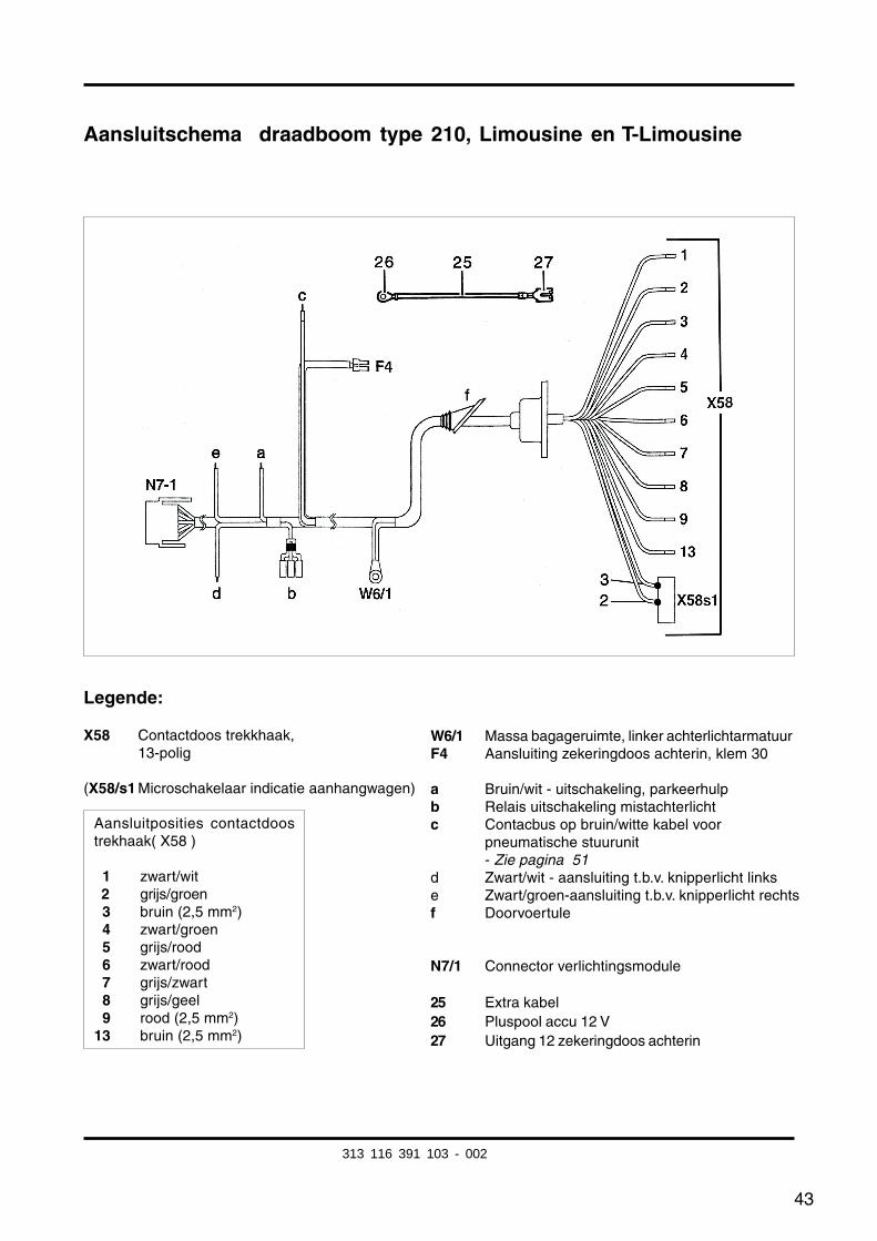
Aansluitschema draadboom type 210, Limousine en T-Limousine
Legende:
X58 Contactdoos trekkhaak,13-polig
(X58/s1 Microschakelaar indicatie aanhangwagen)
W6/1 Massa bagageruimte, linker achterlichtarmatuurF4 Aansluiting zekeringdoos achterin, klem 30
a Bruin/wit - uitschakeling, parkeerhulpb Relais uitschakeling mistachterlichtc Contacbus op bruin/witte kabel voor
pneumatische stuurunit- Zie pagina 51
d Zwart/wit - aansluiting t.b.v. knipperlicht linkse Zwart/groen-aansluiting t.b.v. knipperlicht rechtsf Doorvoertule
N7/1 Connector verlichtingsmodule
25 Extra kabel26 Pluspool accu 12 V27 Uitgang 12 zekeringdoos achterin
Aansluitposities contactdoostrekhaak( X58 )
01 zwart/wit02 grijs/groen03 bruin (2,5 mm2)04 zwart/groen05 grijs/rood06 zwart/rood07 grijs/zwart08 grijs/geel09 rood (2,5 mm2)13 bruin (2,5 mm2)
313 116 391 103 - 002
44
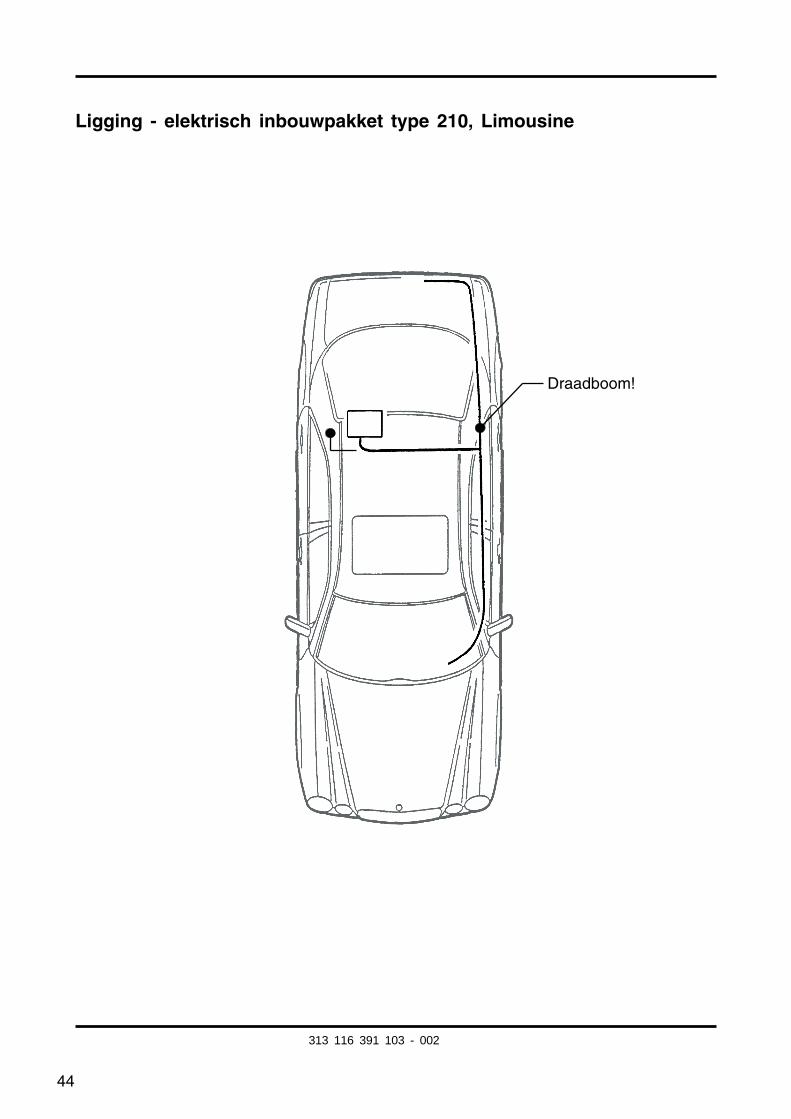
Ligging - elektrisch inbouwpakket type 210, Limousine
Draadboom!
313 116 391 103 - 002
45
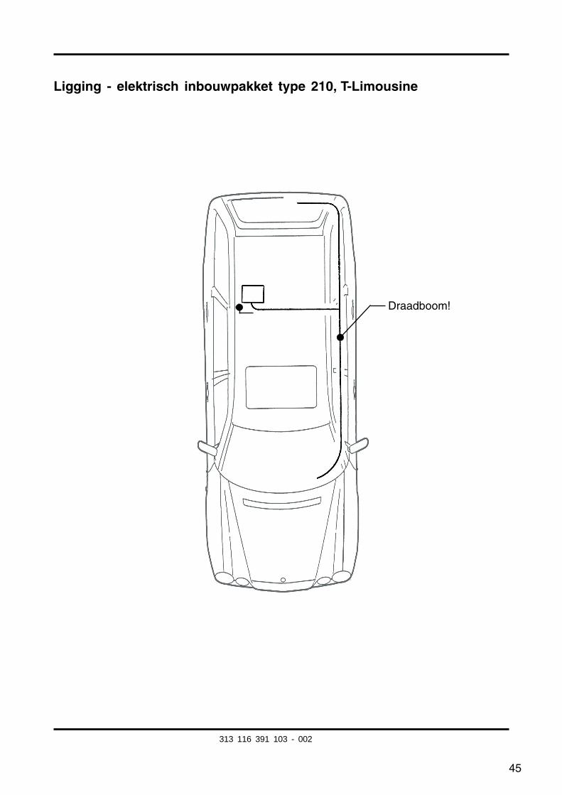
Ligging - elektrisch inbouwpakket type 210, T-Limousine
Draadboom!
313 116 391 103 - 002

46
Gedetaileerde informatie -elektrisch inbouwpakket type 210, Limousine en T-Limousine
De verlichtungsmodule N7-1 uitbouwen
De koppeling van de trekhaak-draaboom op de vrijeaansluitpositie van de verlichtingsmoduleaansluiten.
1
1
313 116 391 103 - 002
47
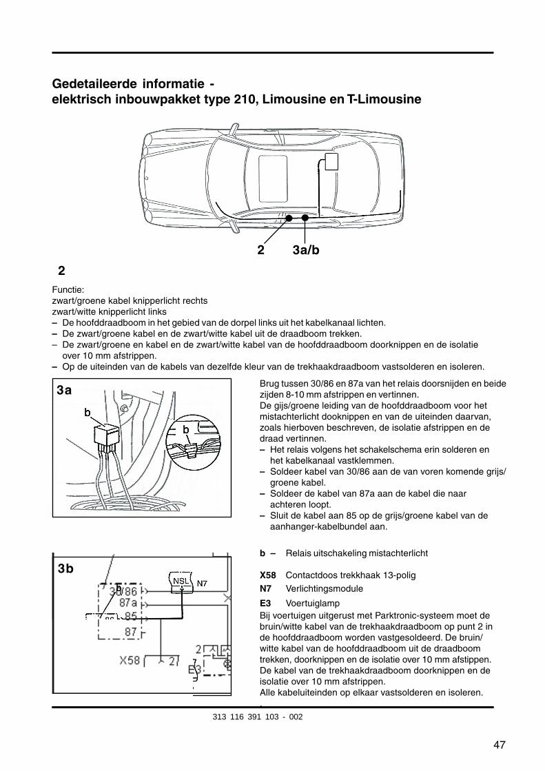
Gedetaileerde informatie -elektrisch inbouwpakket type 210, Limousine en T-Limousine
2
3b
3a
Functie:zwart/groene kabel knipperlicht rechtszwart/witte knipperlicht links– De hoofddraadboom in het gebied van de dorpel links uit het kabelkanaal lichten.– De zwart/groene kabel en de zwart/witte kabel uit de draadboom trekken.– De zwart/groene en kabel en de zwart/witte kabel van de hoofddraadboom doorknippen en de isolatie
over 10 mm afstrippen.– Op de uiteinden van de kabels van dezelfde kleur van de trekhaakdraadboom vastsolderen en isoleren.
Brug tussen 30/86 en 87a van het relais doorsnijden en beidezijden 8-10 mm afstrippen en vertinnen.De gijs/groene leiding van de hoofddraadboom voor hetmistachterlicht dooknippen en van de uiteinden daarvan,zoals hierboven beschreven, de isolatie afstrippen en dedraad vertinnen.– Het relais volgens het schakelschema erin solderen en
het kabelkanaal vastklemmen.– Soldeer kabel van 30/86 aan de van voren komende grijs/
groene kabel.– Soldeer de kabel van 87a aan de kabel die naar
achteren loopt.– Sluit de kabel aan 85 op de grijs/groene kabel van de
aanhanger-kabelbundel aan.
b – Relais uitschakeling mistachterlicht
X58 Contactdoos trekkhaak 13-polig
N7 Verlichtingsmodule
E3 VoertuiglampBij voertuigen uitgerust met Parktronic-systeem moet debruin/witte kabel van de trekhaakdraadboom op punt 2 inde hoofddraadboom worden vastgesoldeerd. De bruin/witte kabel van de hoofddraadboom uit de draadboomtrekken, doorknippen en de isolatie over 10 mm afstippen.De kabel van de trekhaakdraadboom doorknippen en deisolatie over 10 mm afstrippen.Alle kabeluiteinden op elkaar vastsolderen en isoleren..
2 3a/b
313 116 391 103 - 002
fkirakos
Rechteck
fkirakos
Stempel
48
5b
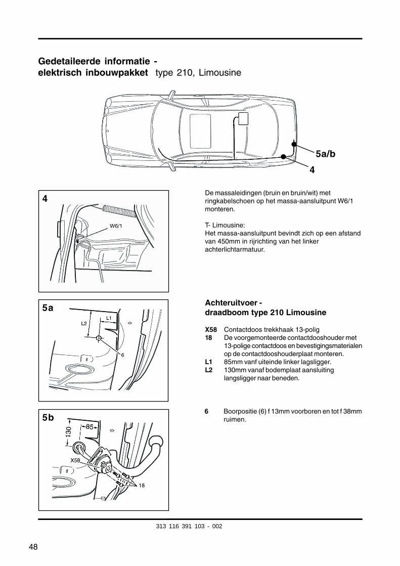
Gedetaileerde informatie -elektrisch inbouwpakket type 210, Limousine
De massaleidingen (bruin en bruin/wit) metringkabelschoen op het massa-aansluitpunt W6/1monteren.
T- Limousine:Het massa-aansluitpunt bevindt zich op een afstandvan 450mm in rijrichting van het linkerachterlichtarmatuur.
4
5a/b
4
5a
6 Boorpositie (6) f 13mm voorboren en tot f 38mmruimen.
Achteruitvoer -draadboom type 210 Limousine
X58 Contactdoos trekkhaak 13-polig18 De voorgemonteerde contactdooshouder met
13-polige contactdoos en bevestigingsmaterialenop de contactdooshouderplaat monteren.
L1 85mm vanf uiteinde linker lagsligger.L2 130mm vanaf bodemplaat aansluiting
langsligger naar beneden.
313 116 391 103 - 002
49
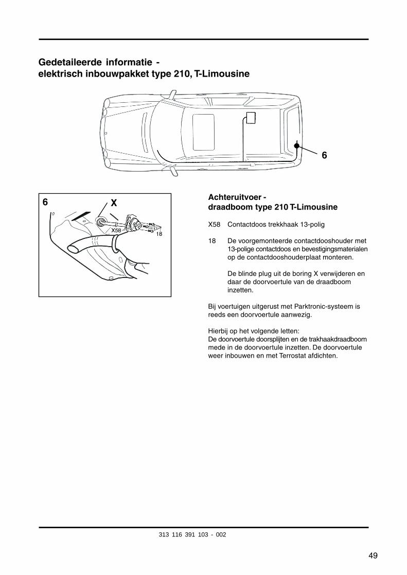
Gedetaileerde informatie -elektrisch inbouwpakket type 210, T-Limousine
Achteruitvoer -draadboom type 210 T-Limousine
X58 Contactdoos trekkhaak 13-polig
18 De voorgemonteerde contactdooshouder met13-polige contactdoos en bevestigingsmaterialenop de contactdooshouderplaat monteren.
De blinde plug uit de boring X verwijderen endaar de doorvoertule van de draadboominzetten.
Bij voertuigen uitgerust met Parktronic-systeem isreeds een doorvoertule aanwezig.
Hierbij op het volgende letten:De doorvoertule doorsplijten en de trakhaakdraadboommede in de doorvoertule inzetten. De doorvoertuleweer inbouwen en met Terrostat afdichten.
6
6 X
313 116 391 103 - 002
50
Gedetaileerde informatie -elektrisch inbouwpakket type 210, Limousine en T-Limousine
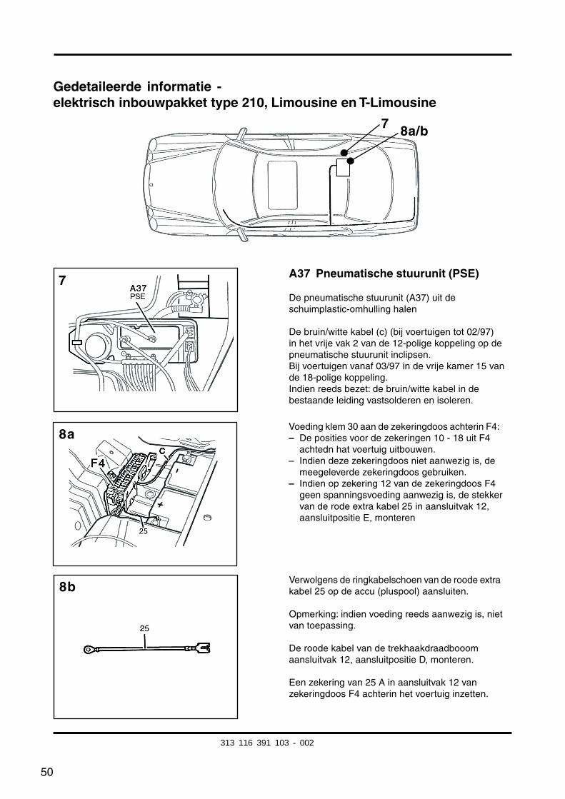
A37 Pneumatische stuurunit (PSE)
De pneumatische stuurunit (A37) uit deschuimplastic-omhulling halen
De bruin/witte kabel (c) (bij voertuigen tot 02/97)in het vrije vak 2 van de 12-polige koppeling op depneumatische stuurunit inclipsen.Bij voertuigen vanaf 03/97 in de vrije kamer 15 vande 18-polige koppeling.Indien reeds bezet: de bruin/witte kabel in debestaande leiding vastsolderen en isoleren.
7 8a/b
Voeding klem 30 aan de zekeringdoos achterin F4:– De posities voor de zekeringen 10 - 18 uit F4
achtedn hat voertuig uitbouwen.– Indien deze zekeringdoos niet aanwezig is, de
meegeleverde zekeringdoos gebruiken.– Indien op zekering 12 van de zekeringdoos F4
geen spanningsvoeding aanwezig is, de stekkervan de rode extra kabel 25 in aansluitvak 12,aansluitpositie E, monteren
Verwolgens de ringkabelschoen van de roode extrakabel 25 op de accu (pluspool) aansluiten.
Opmerking: indien voeding reeds aanwezig is, nietvan toepassing.
De roode kabel van de trekhaakdraadbooomaansluitvak 12, aansluitpositie D, monteren.
Een zekering van 25 A in aansluitvak 12 vanzekeringdoos F4 achterin het voertuig inzetten.
7
8b
8a
313 116 391 103 - 002
51
Gedetaileerde informatie -elektrisch inbouwpakket type 210, Limousine en T-Limousine
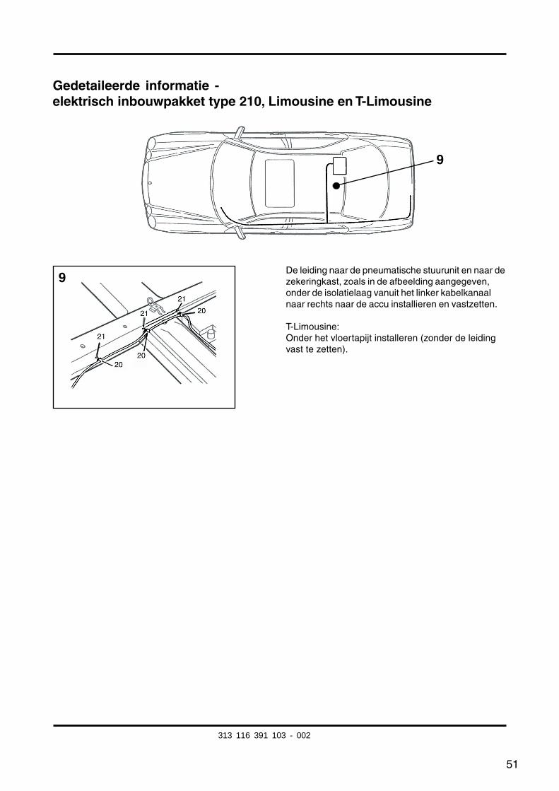
De leiding naar de pneumatische stuurunit en naar dezekeringkast, zoals in de afbeelding aangegeven,onder de isolatielaag vanuit het linker kabelkanaalnaar rechts naar de accu installieren en vastzetten.
T-Limousine:Onder het vloertapijt installeren (zonder de leidingvast te zetten).
9
9
313 116 391 103 - 002
52
Wijziging type 210 v.a. 3/97:
Te herkennen aan:
– Bij modellen vanaf 03/97 is geen contactsleutel voor het starten van de motor aanwezig.
Afb. nr. 7:De bruin/witte leiding in het vrije vak 15 van de 18-polige koppeling van de pneumatischestuurunit inclipsen.
Indien bezet:De bruin/witte kabel in de bestaande de bruin/witte leidingslus vastsolederen en isoleren.
(Bij voertuigen tot 02/97 de bruin/witte kabel in de vrije kamer 2 van de 12-poligekoppeling van de pneumatische controller klemmen.)
313 116 391 103 - 002
53
Aanvullende informatie t.b.v. inbouw in type Coupé 208:
De werkzaamheden voor het type 210 Limousine - echter met uitzondering vanonderstaande veranderingen - ook bij het type Coupé 208 uitvoeren..
Veranderingen:
Algemene werkzaamheden:– Bekleding rechts in bagageruimte ...... uit- en inbouwen
Pag. 43, Ligging draadboom:De dwarsverbindingsleidingen naar de PSE en naar de accu moeten langs de voorstewand van de bagegeruimte worden geïnstalleerd. Daar moeten de te installeren leidingenbij de bestaande hoofddraadboorn worden gevoegd.Hiervoor het inbouwpakket bij de afbinding van de rode 2,5mm2 kabel en de bruin/witte0,75mm2 kabel ca. 1.500 mm verder openen en opnieuw wikkelen
Bij modellen A/C 208: maak een achteruitgang in het reservewielvak, direct achter decontactdooshouder.Aanwijzing: De contactdooshouder aan de dwarsligger van de trekhaak wordt als sjabloongebruikt.
Afb. nr. 7:De bruin/witte leiding in het vrije vak 15 van de 18-polige koppeling van de pneumatischestuurunit inclipsen.Indien bezet: De bruin/witte kabel in de bestaande de bruin/witte leidingslus vastsolederenen isoleren.
Afb.-reeks nr. 8 :A 208:Voeding klem 30 aan de zekeringdoos naast de accu rechtsachter in de bagageruimte.
C 208:Leid de rode kabel voor de voeding van klem 30 ook mee naar voren naar steekkoppelingN7/1.
Voorde preciese aansluitpositie van de leiding, gelieve m.b.t. de bezetting van dezekeringdoos achterin, het deksel van de zekeringdoos te raadplegen.
Voertuigen met Parktronic-systeem (PTS):De bruin/witte leiding van de microschakelaar naar de bruin/witte leiding Parktronic-systeem in het gebied van het rechter achterportier installeren en aansluiten, en verdernaar de pneumatische stuurunit installeren en daar in vak 15 aansluiten.Hierna de verbindingspunten isoleren.
313 116 391 103 - 002
54
Instruzioni di montaggio
Kit elettrico accessori
N. di. ordinazione Westfalia: 313 116 300 113/123/133
Campo d’impiego: Mercedes-Benz Typ 210 tutti i modelliberlina e berlina TMercedes-Benz Typ 208 tutti i modelli
Avvertenze generali:
Prima di iniziare i lavori, leggere le istruzioni per l’uso.
I fori effettuati devono essere sbavati e successivamente trattati con vernice con polvere dizinco.
Il kit elettrico deve essere installato solo da un elettricista, con la batteria scollegata epossibilmente con
l’aiuto di un apparecchio di mantenimento della corrente di riposo.
Tutti i collegamenti brasati devono essere isolati con un tubo flessibile calettato.
L’avaria di un lampeggiatore direzionale, anche del rimorchio, viene segnalatadall’aumento della frequenza di lampeggio. pertanto non è necessario un ulterioredispositivo di controllo per i lampeggiatore direzionali.
Durante lo scollegamento della batteria si possono perdere dati memorizzati!Rispettare le informazioni del produttore.
Il presente kit di cavi è dotato di un dispositivo di disinserimento per i retronebbia.
lmportante!
Fare attenzione alle modifiche per il tipo 210 berlina e berlina T da 3/97 a partire da pagina 65.
Informazioni supplementari per il montaggio nel tipo coupè 208 a partire da pagina 66.
In caso di uso di un adattatore a 7 poli, quest’ultimo deve essere tolto dalla presa altermine della guida con rimorchio.
I
313 116 391 103 - 002
fkirakos
Rechteck
fkirakos
Stempel
55
Mercedes-Benz tipo 210, berlina e berlina T
Elenco dei componenti:
– lstruzioni di montaggio
– Fascio di cavi tipo 210/208 con inserto della presa preconfezionato
– Materiale di fissaggio
– Scatola della presa con microinterruttore
– Scatola della presa con microinterruttore
– Istruzioni di lavoro
Lavori generali:
– Rivestimento sinistro del bagagliaio ........................ smontare, montate– Tappeto sul fondo del bagagliaio ............................. togliere, reinserire– Schienale e sedile posteriori ................................... smontare, montate– Rivestimento entrata sinistra posteriore/anteriore ... smontare, montate– Rivestimento inferiore montante B sinistr ................ smontare, montate– Cunicolo cavi sinistro............................................... aprire, chiudere– Modulo luci .............................................................. smontare, montate
313 116 391 103 - 002
56
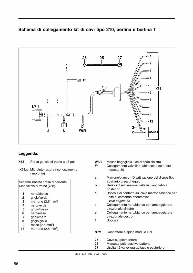
Schema di collegamento kit di cavi tipo 210, berlina e berlina T
Leggenda:
X58 Presa gancio di traino a 13 poli
(X58/s1 Microinterruttore riconoscimentorimorchio)
W6/1 Massa bagagliaio luce di coda sinistraF4 Collegamento valvoliera abitacolo posteriore
morsetto 30
a Marrone/bianco - Disattivazione del dispositivoausiliario di parcheggio
b Relè di disattivazione delle luci antinebbiaposteriori
c Boccola di contatto sul cavo marrone/bianco perunità di comando pneumatica.- vedi pagina 65
d Collegamento nero/bianco per lampeggiatoredirezionale sinistro
e Collegamento nero/bianco per lampeggiatoredirezionale destro
f Boccula
N7/1 Connettore a spina modulo luci
25 Cavo supplementare26 Morsetto polo positivo batteria27 Uscita 12 valvoliera abitacolo posteriore
Schema innesto presa di corrente.Dispositivo di traino (x58)
01 nero/bianco02 grigio/verde03 marrone (2,5 mm2)04 nero/verde05 grigio/rosso06 nero/rosso07 grigio/nero08 grigio/giallo09 rosso (2,5 mm2)13 marrone (2,5 mm2)
313 116 391 103 - 002
57
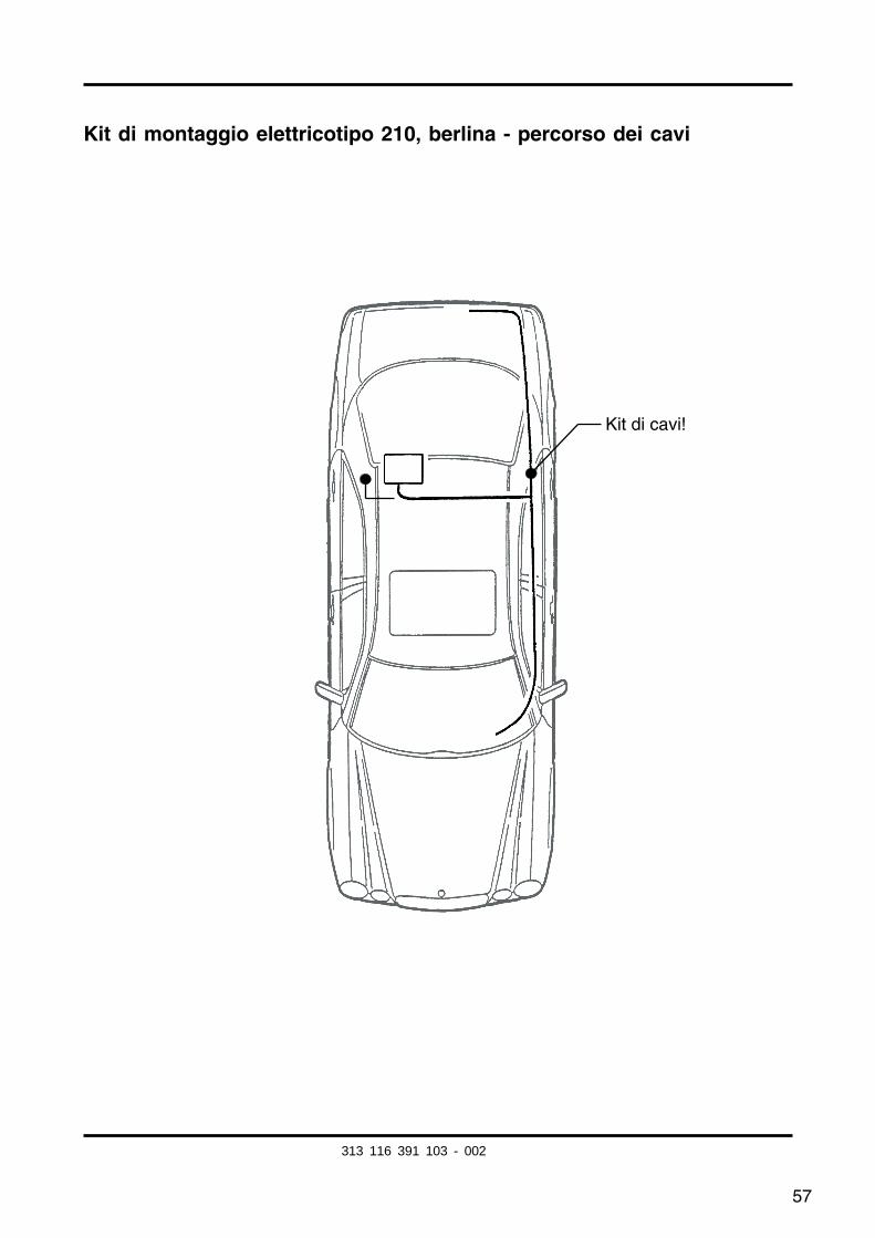
Kit di montaggio elettricotipo 210, berlina - percorso dei cavi
Kit di cavi!
313 116 391 103 - 002
58
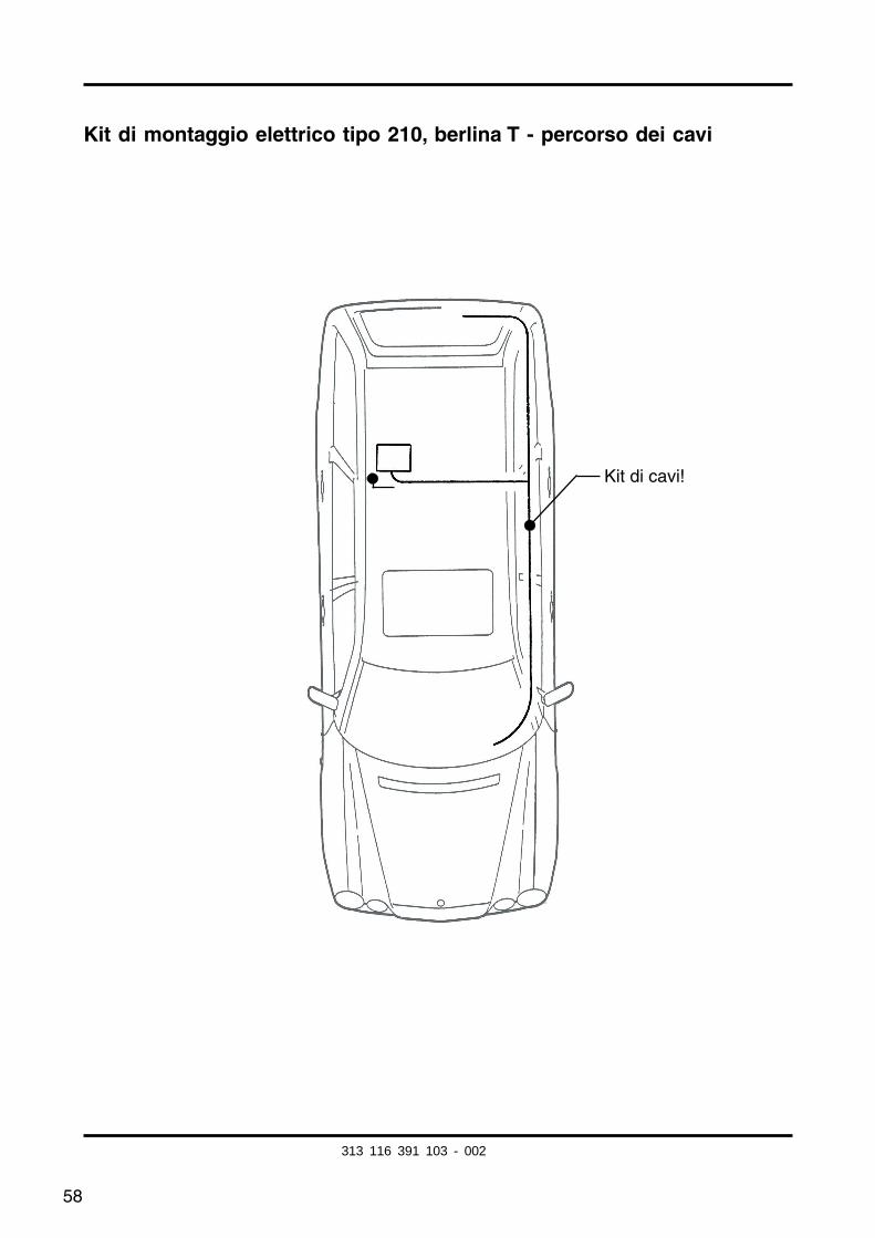
Kit di montaggio elettrico tipo 210, berlina T - percorso dei cavi
Kit di cavi!
313 116 391 103 - 002
59
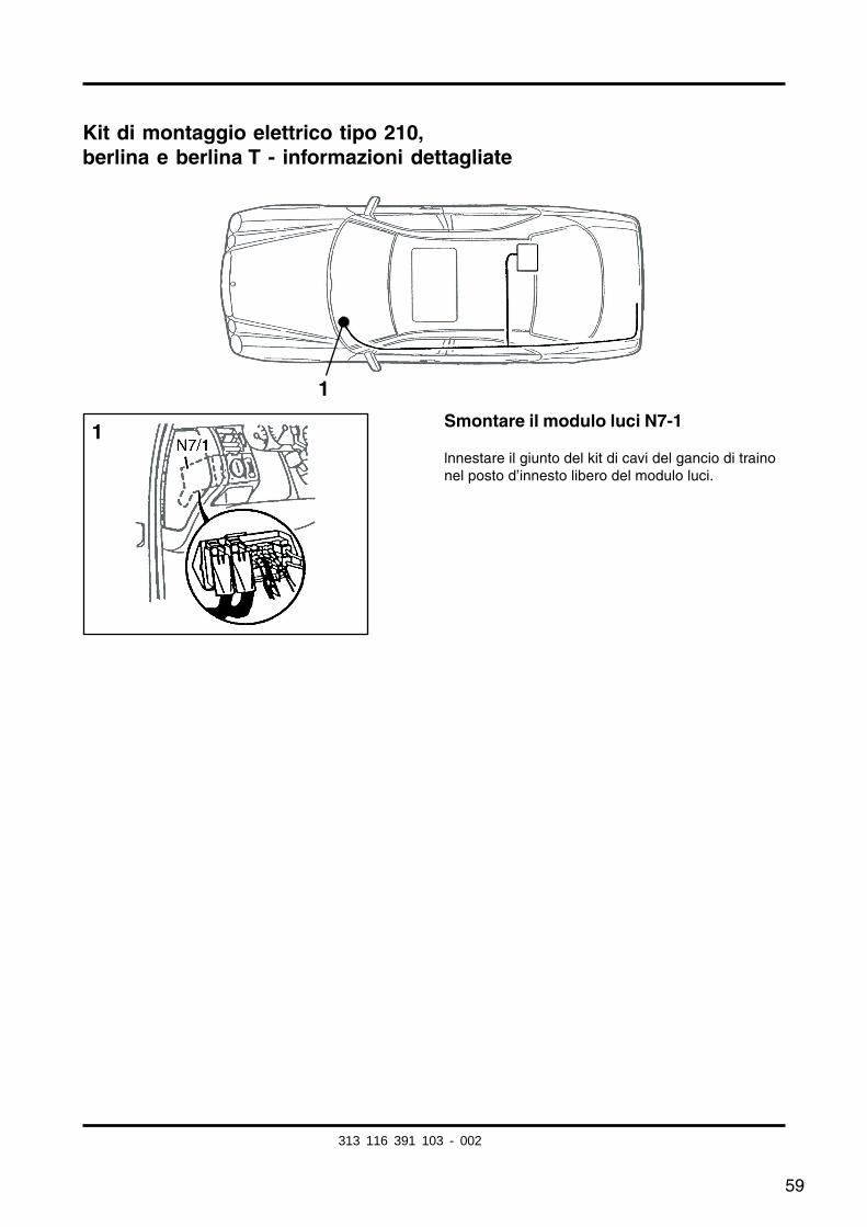
Kit di montaggio elettrico tipo 210,berlina e berlina T - informazioni dettagliate
Smontare il modulo luci N7-1
lnnestare il giunto del kit di cavi del gancio di trainonel posto d’innesto libero del modulo luci.
1
1
313 116 391 103 - 002
60
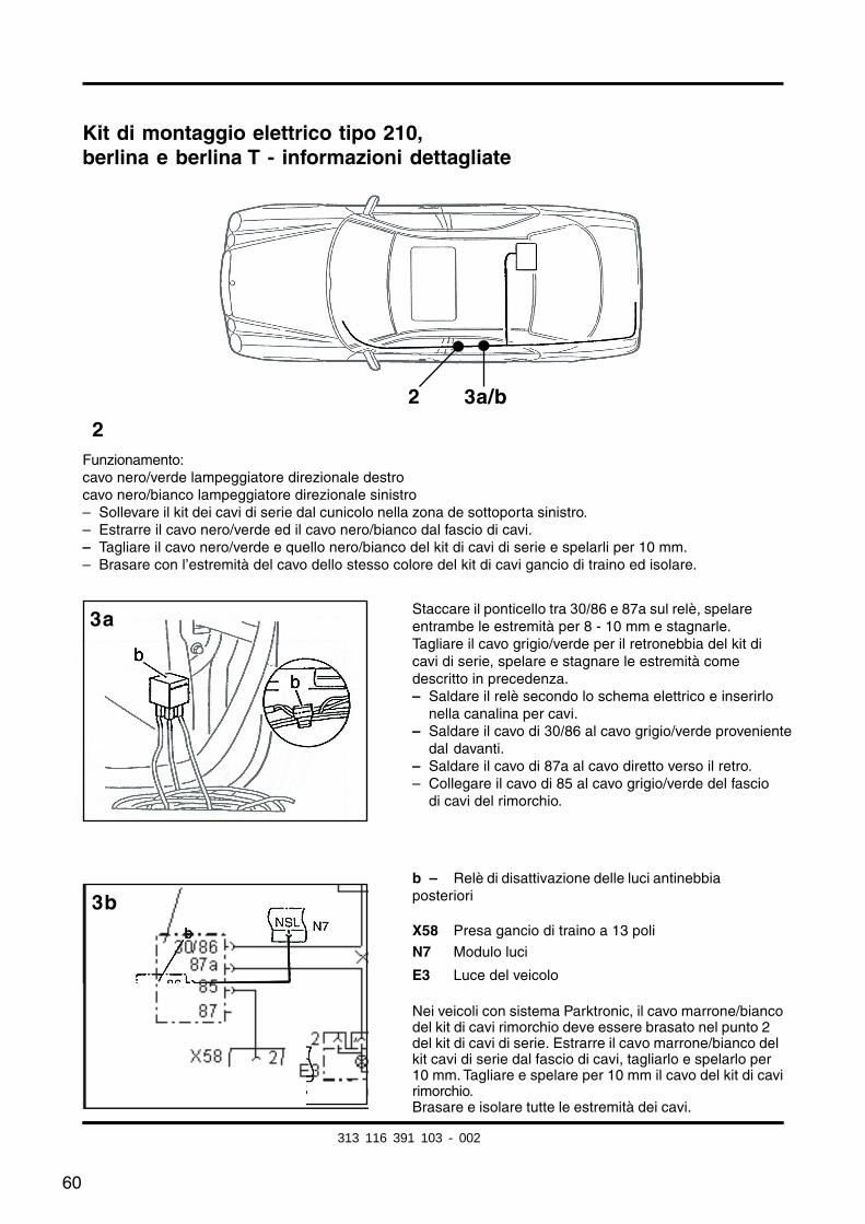
Kit di montaggio elettrico tipo 210,berlina e berlina T - informazioni dettagliate
2
3b
3a
Funzionamento:cavo nero/verde lampeggiatore direzionale destrocavo nero/bianco lampeggiatore direzionale sinistro– Sollevare il kit dei cavi di serie dal cunicolo nella zona de sottoporta sinistro.– Estrarre il cavo nero/verde ed il cavo nero/bianco dal fascio di cavi.– Tagliare il cavo nero/verde e quello nero/bianco del kit di cavi di serie e spelarli per 10 mm.– Brasare con l’estremità del cavo dello stesso colore del kit di cavi gancio di traino ed isolare.
Staccare il ponticello tra 30/86 e 87a sul relè, spelareentrambe le estremità per 8 - 10 mm e stagnarle.Tagliare il cavo grigio/verde per il retronebbia del kit dicavi di serie, spelare e stagnare le estremità comedescritto in precedenza.– Saldare il relè secondo lo schema elettrico e inserirlo
nella canalina per cavi.– Saldare il cavo di 30/86 al cavo grigio/verde proveniente
dal davanti.– Saldare il cavo di 87a al cavo diretto verso il retro.– Collegare il cavo di 85 al cavo grigio/verde del fascio
di cavi del rimorchio.
b – Relè di disattivazione delle luci antinebbiaposteriori
X58 Presa gancio di traino a 13 poli
N7 Modulo luci
E3 Luce del veicolo
Nei veicoli con sistema Parktronic, il cavo marrone/biancodel kit di cavi rimorchio deve essere brasato nel punto 2del kit di cavi di serie. Estrarre il cavo marrone/bianco delkit cavi di serie dal fascio di cavi, tagliarlo e spelarlo per10 mm. Tagliare e spelare per 10 mm il cavo del kit di cavirimorchio.Brasare e isolare tutte le estremità dei cavi.
2 3a/b
313 116 391 103 - 002
fkirakos
Rechteck
fkirakos
Stempel
61
5b
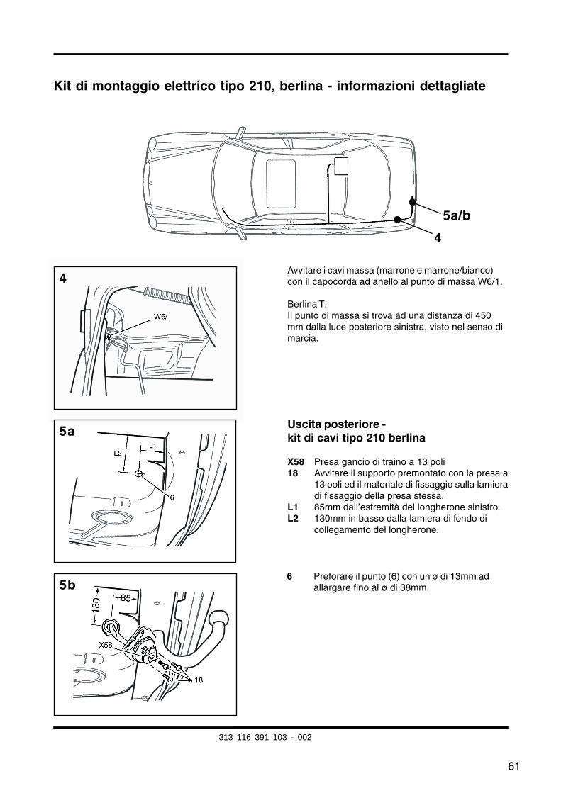
Kit di montaggio elettrico tipo 210, berlina - informazioni dettagliate
Avvitare i cavi massa (marrone e marrone/bianco)con il capocorda ad anello al punto di massa W6/1.
Berlina T:Il punto di massa si trova ad una distanza di 450mm dalla luce posteriore sinistra, visto nel senso dimarcia.
4
5a/b
4
5a
6 Preforare il punto (6) con un ø di 13mm adallargare fino al ø di 38mm.
Uscita posteriore -kit di cavi tipo 210 berlina
X58 Presa gancio di traino a 13 poli18 Avvitare il supporto premontato con la presa a
13 poli ed il materiale di fissaggio sulla lamieradi fissaggio della presa stessa.
L1 85mm dall’estremità del longherone sinistro.L2 130mm in basso dalla lamiera di fondo di
collegamento del longherone.
313 116 391 103 - 002
62
Kit di montaggio elettrico tipo 210, berlina T - informazioni dettagliate
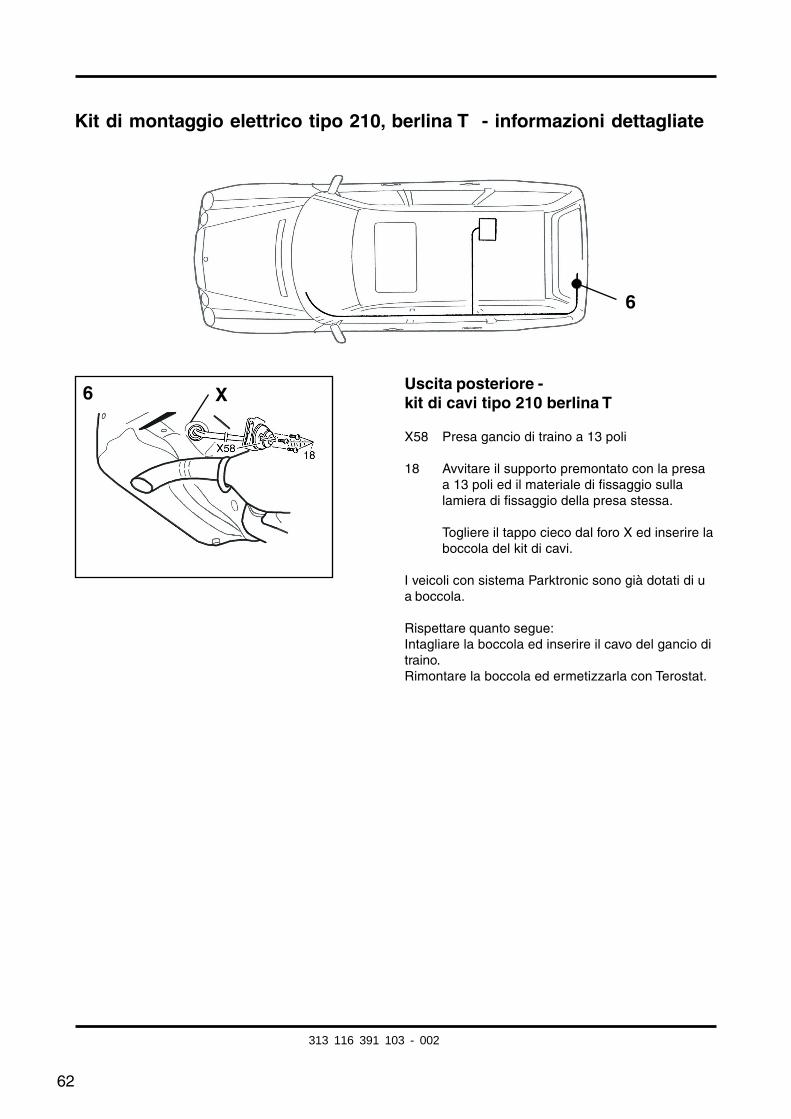
Uscita posteriore -kit di cavi tipo 210 berlina T
X58 Presa gancio di traino a 13 poli
18 Avvitare il supporto premontato con la presaa 13 poli ed il materiale di fissaggio sullalamiera di fissaggio della presa stessa.
Togliere il tappo cieco dal foro X ed inserire laboccola del kit di cavi.
I veicoli con sistema Parktronic sono già dotati di ua boccola.
Rispettare quanto segue:Intagliare la boccola ed inserire il cavo del gancio ditraino.Rimontare la boccola ed ermetizzarla con Terostat.
6
6 X
313 116 391 103 - 002
63
Kit di montaggio elettrico tipo 210,berlina e berlina T - Informazioni dettagliate
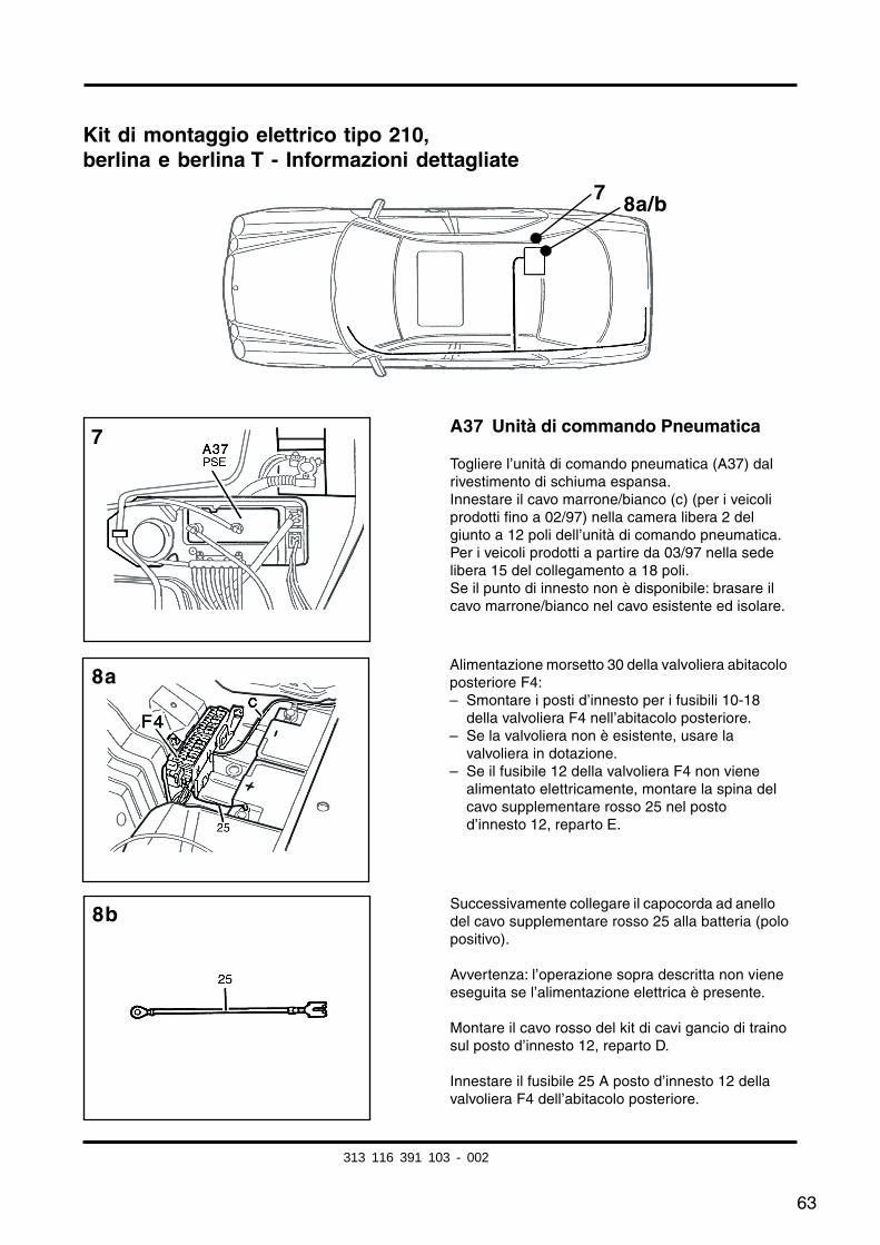
A37 Unità di commando Pneumatica
Togliere l’unità di comando pneumatica (A37) dalrivestimento di schiuma espansa.Innestare il cavo marrone/bianco (c) (per i veicoliprodotti fino a 02/97) nella camera libera 2 delgiunto a 12 poli dell’unità di comando pneumatica.Per i veicoli prodotti a partire da 03/97 nella sedelibera 15 del collegamento a 18 poli.Se il punto di innesto non è disponibile: brasare ilcavo marrone/bianco nel cavo esistente ed isolare.
7 8a/b
Alimentazione morsetto 30 della valvoliera abitacoloposteriore F4:– Smontare i posti d’innesto per i fusibili 10-18
della valvoliera F4 nell’abitacolo posteriore.– Se la valvoliera non è esistente, usare la
valvoliera in dotazione.– Se il fusibile 12 della valvoliera F4 non viene
alimentato elettricamente, montare la spina delcavo supplementare rosso 25 nel postod’innesto 12, reparto E.
Successivamente collegare il capocorda ad anellodel cavo supplementare rosso 25 alla batteria (polopositivo).
Avvertenza: l’operazione sopra descritta non vieneeseguita se l’alimentazione elettrica è presente.
Montare il cavo rosso del kit di cavi gancio di trainosul posto d’innesto 12, reparto D.
Innestare il fusibile 25 A posto d’innesto 12 dellavalvoliera F4 dell’abitacolo posteriore.
7
8b
8a
313 116 391 103 - 002
64
Kit di montaggio elettrico tipo 210,berlina e berlina T - Informazioni dettagliate
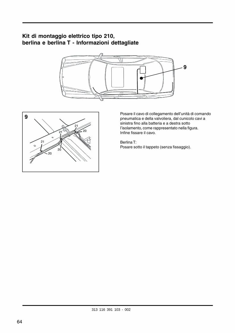
Posare il cavo di collegamento dell’unità di comandopneumatica e della valvoliera, dal cunicolo cavi asinistra fino alla batteria e a destra sottol’isolamento, come rappresentato nella figura.Infine fissare il cavo.
Berlina T:Posare sotto il tappeto (senza fissaggio).
9
9
313 116 391 103 - 002
65
Modifica tipo 210 da 3/97:
Segno di identificazione:
– Sui modelli prodotti a partire da 03/97 non è presente l’ingegno della chiave per l’avviamento del motore.
Figura n. 7:Innestare il cavo marrone/bianco nella camera disponibile 15 del giunto a 18 poli dell’unitádi comando pneumatica.
Se il posto d’innesto non è disponibile:brasare il cavo marrone/bianco nel cavo marrone/bianco esstente ed isolare.
(Per i veicoli fino a 02/97: agganciare il cavo marrone/bianco nella sede libera 2 delcollegamento a 12 poli dell’unità di controllo pneumatica.)
313 116 391 103 - 002
66
Informazioni supplmentari per il montaggio nel tipo coupé 208:
Le operazioni descritte per il tipo210 berlina sono valide anche per il tipo coupé 208, adeccezione delle seguenti modifiche.
Modifiche:
Lavori generali:– Rivestimento destro del bagagliaio ................ smontare, montare
Pagina 56, percorso del kit di cavi:I cavi di collegamento trasversale della PSE e della batteria vengono posati sul pannelloanteriore del bagagliaio. I cavi da posare devono essere aggiunti al fascio di cavi giàesistente.A tal fine aprire di altri 1500 mm circa il kit di montaggio vicino al cavo rosso di 2,5mm2
e al marrone/bianco di 0,75mm2 e riavvolgere.
Per i modelli A/C 208: praticare un foro di uscita posteriore appena dietro il portapresa nell’alloggiamento per la ruota di scorta.Nota: il portapresa sulla traversa del supporto per traino funge da sagoma.
Figura n. 7:Innestare il cavo marrone/bianco nella camera disponibile 15 del giunto a 18 poli dell’unitádi comando pneumatica.Se il posto d’innesto non è disponibile: brasare il cavo marrone/bianco nel cavo marrone/bianco esstente ed isolare.
Serie di figure n.8:A 208:Alimentazione morsetto 30 della valvoliera accanto alla batteria, nella perle posterioredestra del bagagliaio.
C 208:Portare anche il cavo rosso di alimentazione del morsetto 30 in avanti verso ilcollegamento a spina N7/1.
Per determinare l’esatto posto d’innesto del cavo, guardare lo schema di collegamentodella valvoliera dell’abitacolo posteriore nel rivestimento.
Veicoli con sistema Parktronic (PTS):Posare il cavo marrone/bianco dal microinterruttore al cavo marrone/bianco del sistemaParktronic nella zona della porta posteriore destra, collegare, posare ulteriormente finoall’unità di comando pneumatica ed innestare nella camera 15 di quest’ultima.Successivamente isolare tutti i punti di collegamento
313 116 391 103 - 002
67
Instrucciones de montaje
Juego de accesorios eléctrcos
Núm. de pedido Westfalia: 313 116 300 113/123/133
Ambito de utilización: Mercedes-Benz modelo 210, todas las versionessedán y familarMercedes-Benz modelo 208, todas las versiones
Indicaciones de carácter general:
Las las instrucciones da montaje antes de comenzar los trabajos.
Desbarbar los taladros efectuados y aplicarles una capa de pintura de polvo de cinc acontinuación.
La instalación del juego eléctrico debe ser efectuada exclusivamente por personalespecializado y con la batería desembornada, en lo posible con ayuda de un dispositivomantenedor de corriente de reposo.
Todas las uniones soldadas deberán aislarse mediante tubos flexibles contráibles.
EI fallo de una luz intermitente, incluidas las del remolque, se señaliza mediante laelevación de la frecuencia de intermitencia, por lo que resulta innecesario efectuar uncontrol visual adicional de los intermitentes.
Al desconectar la batería pueden perderse datos memorizados.Obsérvense las informaciones del fabbricante.
Este juego de cables va equipado con un sistema de desconexión de las luces antinieblatraseras.
Importante!
Obsérvense las modifinciones para los modelos 210 sedán y familiar desde 3/97 quefiguran a partir de la página 78.
Información adicional par el montaje en el modelo coupé 208 a partir de la página 79.
En caso de utilizar un adaptador de 7 polos deberá retirarse de nuevo de la caja deenchufe un avez finalizado el servicio con remolque.
E
313 116 391 103 - 002
fkirakos
Rechteck
fkirakos
Stempel
68
Mercedes-Benz modelo 210, sedán y familiar
Lista de piezas:
– Instrucciones de montaje
– Juego de cables tipo 210/208 con enchufe preconfeccionado
– Material de fijación
– Carcasa para enchufe con microinterruptor
– Relé de desconexión luz antiniebla trasera
– Instrucciones para el trabajo
Trabajos de carácter general:
– Revestimiento izquierdo del maletero ........................ desmontar y montar– Moqueta del piso del maletero ................................... retirar y colocar– Respaldo y banqueta del asiento trasero ................... desmontar y montar– Revestimiento umbral izquierdo delantero y trasero .. desmontar y montar– Revestimianto inferior montante B izquierdo .............. desmontar y montar– Conducto de cables izquierdo .................................... abrir y cerrar– Módulo de luces ......................................................... desmontar y montar
313 116 391 103 - 002
69
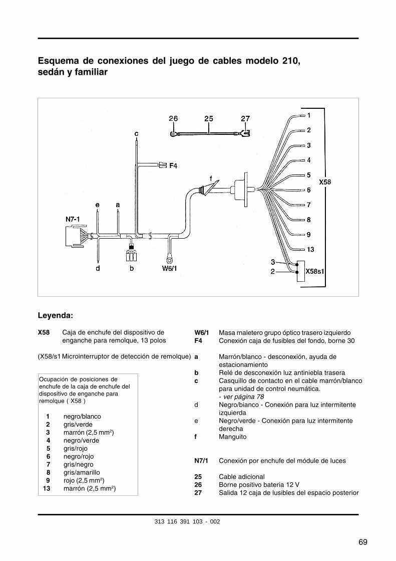
Esquema de conexiones del juego de cables modelo 210,sedán y familiar
Leyenda:
X58 Caja de enchufe del dispositivo deenganche para remolque, 13 polos
(X58/s1 Microinterruptor de detección de remolque)
W6/1 Masa rnaletero grupo óptico trasero izquierdoF4 Conexión caja de fusibles del fondo, borne 30
a Marrón/blanco - desconexión, ayuda deestacionamiento
b Relé de desconexión luz antiniebla traserac Casquillo de contacto en el cable marrón/blanco
para unidad de control neumática.- ver página 78
d Negro/bianco - Conexión para luz intermitenteizquierda
e Negro/verde - Conexión para luz intermitentederecha
f Manguito
N7/1 Conexión por enchufe del módule de luces
25 Cable adicional26 Borne positivo bateria 12 V27 Salida 12 caja de lusibles del espacio posterior
Ocupación de posiciones deenchufe de la caja de enchufe deldispositivo de enganche pararemolque ( X58 )
01 negro/blanco02 gris/verde03 marrón (2,5 mm2)04 negro/verde05 gris/rojo06 negro/rojo07 gris/negro08 gris/amarillo09 rojo (2,5 mm2)13 marrón (2,5 mm2)
313 116 391 103 - 002
70
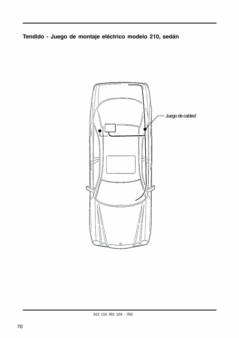
Tendido - Juego de montaje eléctrico modelo 210, sedán
Juego de cables!
313 116 391 103 - 002
71
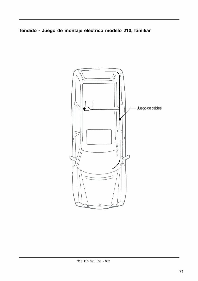
Tendido - Juego de montaje eléctrico modelo 210, familiar
Juego de cables!
313 116 391 103 - 002

72
Información detallada -Juego de montaje eléctrico modelo 210, sedán y familiar
Desmontar el módulo de luces
Calar el acoplamiento del juego de cables deldispositivo de enganche para remolque en laposición enchufable libre del módulo de luces.
1
1
313 116 391 103 - 002
73
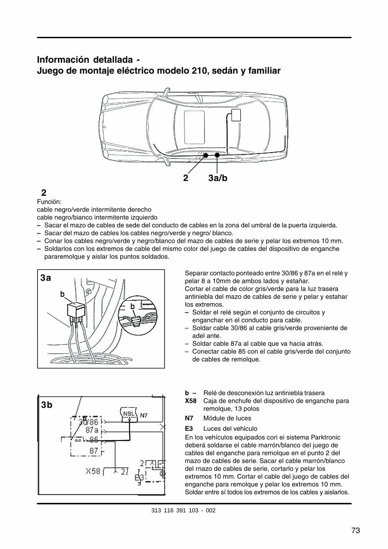
Información detallada -Juego de montaje eléctrico modelo 210, sedán y familiar
2
3b
3a
Función:cable negro/verde intermitente derechocable negro/bianco intermitente izquierdo– Sacar el mazo de cables de sede del conducto de cables en la zona del umbral de la puerta izquierda.– Sacar del mazo de cables los cables negro/verde y negro/ blanco.– Conar los cables negro/verde y negro/blanco del mazo de cables de serie y pelar los extremos 10 mm.– Soldarlos con los extremos de cable del mismo color del juego de cables del dispositivo de enganche
pararemolque y aislar los puntos soldados.
Separar contacto ponteado entre 30/86 y 87a en el relé ypelar 8 a 10mm de ambos lados y estañar.Cortar el cable de color gris/verde para la luz traseraantiniebla del mazo de cables de serie y pelar y estaharlos extremos.– Soldar el relé según el conjunto de circuitos y
enganchar en el conducto para cable.– Soldar cable 30/86 al cable gris/verde proveniente de
adel ante.– Soldar cable 87a al cable que va hacia atrás.– Conectar cable 85 con el cable gris/verde del conjunto
de cables de remolque.
b – Relé de desconexión luz antiniebla traseraX58 Caja de enchufe del dispositivo de enganche para
remolque, 13 polos
N7 Módule de luces
E3 Luces del vehiculoEn los vehículos equipados cori ei sistema Parktronicdeberá soldarse el cable marrón/blanco del juego decables del enganche para remolque en el punto 2 delmazo de cables de serie. Sacar el cable marrón/blancodel rnazo de cables de serie, cortarlo y pelar losextremos 10 mm. Cortar el cable del juego de cables delenganche para remolque y pelar los extremos 10 mm.Soldar entre sí todos los extremos de los cables y aislarlos.
2 3a/b
313 116 391 103 - 002
fkirakos
Rechteck
fkirakos
Stempel
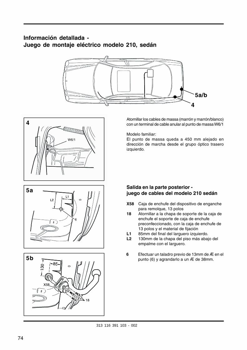
74
5b
Información detallada -Juego de montaje eléctrico modelo 210, sedán
Atornillar los cables de massa (marrón y marrón/blanco)con un terminal de cable anular al punto de massa W6/1
Modelo familiar:El punto de massa queda a 450 mm alejado endirección de marcha desde el grupo óptico traseroizquierdo.
4
5a/b
4
5a
6 Efectuar un taladro previo de 13mm de Æ en elpunto (6) y agrandarlo a un Æ de 38mm.
Salida en la parte posterior -juego de cables del modelo 210 sedán
X58 Caja de enchufe del dispositivo de enganchepara remolque, 13 polos
18 Atornillar a la chapa de soporte de la caja deenchufe el soporte de caja de enchufepreconfeccionado, con la caja de enchufe de13 polos y el material de fijación
L1 85mm del final del larguero izquierdo.L2 130mm de la chapa del piso más abajo del
empalme con el larguero.
313 116 391 103 - 002
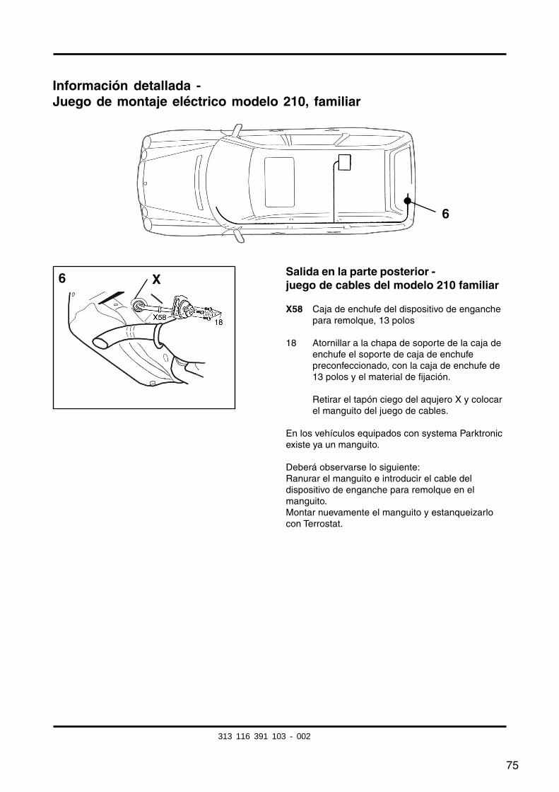
75
Información detallada -Juego de montaje eléctrico modelo 210, familiar
Salida en la parte posterior -juego de cables del modelo 210 familiar
X58 Caja de enchufe del dispositivo de enganchepara remolque, 13 polos
18 Atornillar a la chapa de soporte de la caja deenchufe el soporte de caja de enchufepreconfeccionado, con la caja de enchufe de13 polos y el material de fijación.
Retirar el tapón ciego del aqujero X y colocarel manguito del juego de cables.
En los vehículos equipados con systema Parktronicexiste ya un manguito.
Deberá observarse lo siguiente:Ranurar el manguito e introducir el cable deldispositivo de enganche para remolque en elmanguito.Montar nuevamente el manguito y estanqueizarlocon Terrostat.
6
6 X
313 116 391 103 - 002
76
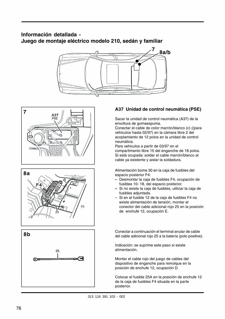
Información detallada -Juego de montaje eléctrico modelo 210, sedán y familiar
A37 Unidad de control neumática (PSE)
Sacar la unidad de control neumática (A37) de laenvoltura de gomaespuma.Conectar el cable de color marrón/blanco (c) ((paravehiculos hasta 02/97) en la cámara libre 2 delacoplamiento de 12 polos en la unidad de controlneumática.Para vehiculos a partir de 03/97 en elcompartimento libre 15 del enganche de 18 polos.Si está ocupada: soldar el cable marrón/blanco alcable ya existente y aislar la soldadura.
7 8a/b
Alimentación bome 30 en la caja de fusibles delespacio posterior F4:– Desmontar la caja de fusibles F4, ocupación de
fusibles 10- 18, del espacio posterior.– Si no existe la caja de fusibles, utilizar la caja de
fusibles adjuntada.– Si en el fusible 12 de la caja de fusibles F4 no
existe alimentación de tensión, montar elconector del cable adicional rojo 25 en la posiciónde enchufe 12, ocupación E.
Conectar a continuación el terminal anular de cabledel cable adicional rojo 25 a la batería (polo positive).
Indicación: se suprime este paso si existealimentación.
Montar el cable rojo del juego de cables deldispositivo de enganche para remolque en laposición de enchufe 12, ocupación D.
Colocar el fusible 25A en la posición de enchufe 12de la caja de fusibles F4 situada en la parteposterior.
7
8b
8a
313 116 391 103 - 002
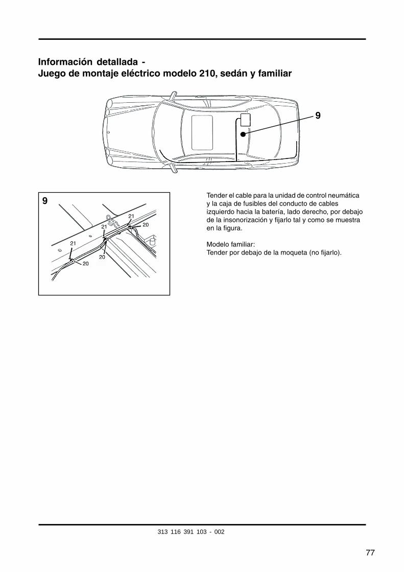
77
Información detallada -Juego de montaje eléctrico modelo 210, sedán y familiar
Tender el cable para la unidad de control neumáticay la caja de fusibles del conducto de cablesizquierdo hacia la batería, lado derecho, por debajode la insonorización y fijarlo tal y como se muestraen la figura.
Modelo familiar:Tender por debajo de la moqueta (no fijarlo).
9
9
313 116 391 103 - 002
78
Modificación modelo 210 a partir de 3/97:
Signo distintivo:
– Los modelos a partir de 03/97 no disponen de paletón para el arranque del motor.
Fig núm. 7:Conectar el cable de color marrón/blanco en la cámara libre 15 del acoplamiento de 18polos de la unidad de control neumática.
Si está ocupada:soldar el cable marrón/blanco en el bucle de cable existente marrón/blanco y aislar lasoldadura.
(Para los modelos hasta 02/97 enganchar el cable marrón /blanco en el compartimentolibre 2 del enganche de 12 polos de la unidad de control neumática.)
313 116 391 103 - 002
79
Información adicional para el montaje en el modelo coupé 208:
Seguir los pasos de trabajo efectuados para el modelo 210 sedán también en el caso delmodelo coupé 208, con excepción de las siguientes modificaciones.
Modificationes:
Trabajos de carácter general:– Revestimiento del maletero, lado derecho ..... desmontar y montar
Página 69, tendido del juego de cables:EI tendido de cables de la unión transversal hacia la PSE y la batería se efectúa en lapared delantera del maletero. En dicho punto se fijarán al mazo de cables ya existente losnuevos cables.Separar para ello el juego de montaje del trenzado de los cablas rojo de 2,5mm2 y marrón/blanco 0,75mm2 aproximadamente 1.500 mm y trenzarlos nuevamente
Para modelos A/C 208 conformar la salida trasera detrás del soporte del enchufe en lacavidad de la rueda de reserva.Nota: El soporte de enchufe en el travesaño del dispositivo de remolque sirve comoplantilla.
Fig. núm. 7:Conectar el cable de color marrón/blanco en la cámara libre 15 del acoplamiento de 18polos de la unidad de control neumática.Si está ocupada: soldar el cable marrón/blanco en el bucle de cable existente marrón/blanco y aislar la soldadura.
Fig. núm. 8 :A 208:Alimentación del borne 30 en la caja de fusibles junto a la batería, parte trasera derechadel maletero.
C 208:Tender el cable rojo de alimentación del borne 30 hacia adelante hasta el enganche deconexión N7/1.
La posición de enchlife exacta del cable se determinará mediante la ocupación en la tapade la caja de fusibles del espacio posterior.
Vehiculos con sistema Parktronic (PTS):Tender el cable marrón/blanco del microinterruptor hacia el cable marrón/blanco delsistema Parktronic en la zona de la puerta trasera derecha, unirlos entre sí y sequir eitendido hasta la unidad de control neumática, conectándolos en la cámara 15 de la misma.Aislar a continuación los puntos soldados.
313 116 391 103 - 002

80
313 116 391 102 24/02