B54-4486 final - KENWOODmanual.kenwood.com/files/B54-4486-00.pdfBB54-4486_final.indd...
32
© B54-4486-00/00 (MV/XV) DDX8639 MONITOR WITH 6 DISC DVD CHANGER RECEIVER INSTALLATION MANUAL 具備 6 片 DVD 換片接收機功能的顯示器 安裝說明書 6 디스크 DVD 체인저 리시버 장착 모니터 설치 설명서
Transcript of B54-4486 final - KENWOODmanual.kenwood.com/files/B54-4486-00.pdfBB54-4486_final.indd...

© B54-4486-00/00 (MV/XV)
DDX8639MONITOR WITH 6 DISC DVD CHANGER RECEIVER
INSTALLATION MANUAL具備 6片 DVD換片接收機功能的顯示器
安裝說明書6 디스크 DVD 체인저 리시버 장착 모니터
설치 설명서
B54-4486_final.indd 1 06.9.14 5:23:20 PM

2 | English
Accessories
1
..........1
2
..........1
3
..........2
4
..........1
5
..........1
6
..........1
7
..........6
8
..........6
B54-4486_final.indd 2B54-4486_final.indd 2 06.9.14 5:18:33 PM06.9.14 5:18:33 PM

English | 3
Installation Procedure1. To prevent a short circuit, remove the key from the
ignition and disconnect the - battery.
2. Make the proper input and output wire connections
for each unit.
3. Connect the speaker wires of the wiring harness.
4. Connect the wiring harness wires in the following
order: ground, battery, ignition.
5. Connect the wiring harness connector to the unit.
6. Install the unit in your car.
7. Reconnect the - battery.
8. Press the reset button.
2WARNING
• If you connect the ignition wire (red) and the
battery wire (yellow) to the car chassis (ground),
you may cause a short circuit, that in turn may start
a fire. Always connect those wires to the power
source running through the fuse box.
• Do not cut out the fuse from the ignition wire (red)
and the battery wire (yellow). The power supply
must be connected to the wires via the fuse.
2CAUTION
• If your car’s ignition does not have an ACC position,
connect the ignition wires to a power source that
can be turned on and off with the ignition key. If
you connect the ignition wire to a power source
with a constant voltage supply, as with battery
wires, the battery may die.
• If the console has a lid, make sure to install the
unit so that the faceplate will not hit the lid when
closing and opening.
• If the fuse blows, first make sure the wires aren’t
touching to cause a short circuit, then replace the
old fuse with one with the same rating.
• Insulate unconnected wires with vinyl tape or other
similar material. To prevent a short circuit, do not
remove the caps on the ends of the unconnected
wires or the terminals.
• Connect the speaker wires correctly to the terminals
to which they correspond. The unit may be
damaged or fail to work if you share the - wires or
ground them to any metal part in the car.
• When only two speakers are being connected to the
system, connect the connectors either to both the
front output terminals or to both the rear output
terminals (do not mix front and rear). For example,
if you connect the + connector of the left speaker
to a front output terminal, do not connect the -
connector to a rear output terminal.
• After the unit is installed, check whether the brake
lamps, blinkers, wipers, etc. on the car are working
properly.
• Mount the unit so that the mounting angle is 30° or
less.
• This unit has the cooling fan (page 6) to decrease the
internal temperature. Do not mount the unit in a
place where the cooling fan of the unit are blocked.
Blocking these openings will inhibit the cooling of
the internal temperature and result in malfunction.
B54-4486_final.indd 3B54-4486_final.indd 3 06.9.14 5:18:34 PM06.9.14 5:18:34 PM
4 | English
Connection
If you connect the ignition wire (red) and the battery wire (yellow) to the car chassis (ground), you may cause a short circuit, that in turn may start a fire. Always connect those wires to the power source running through the fuse box.
Antenna Cord FM/AM antenna input
Connect to the vehicle's parking brake detection switch harness using the supplied relay connector.
To vehicle's reverse lamp harness
To car light control switch
Reveres sensor wire (Purple/White)
For the sake of safety, be sure to connect the parking sensor.
Dimmer control wire (Orange/White)
When using the optional power amplifier, connect to its power control terminal.
To "EXT.AMP.CONT." terminal of the amplifier having the external amp control function.
TV tuner (Optional)
Parking sensor wire (Light Green)
Battery wire (Yellow)
Ground wire (Black) - (To car chassis)
FUSE ( 15A )
Ignition wire (Red)
If no connections are made, do not let the cable come out from the tab.
Steering remote control input (Light Blue/Yellow)
To steering remote
Connect to the terminal that is grounded when either the telephone rings or during conversation.
Depending on what antenna you are using, connect either to the control terminal of the
motor antenna, or to the power terminal for the booster amplifier of the film-type antenna.
If no connections are made, do not let the cable come out from the tab.
Mute wire (Brown)
Motor antenna control wire (Blue)
Power control wire (Blue/White)
External amplifier control wire (Pink/Black)
To connect the Kenwood navigation system, consult your navigation manual.
Ignition key switch
ACC
Car fuse box (Main fuse)
Battery
Car fuse box
B54-4486_final.indd 4B54-4486_final.indd 4 06.9.14 5:18:35 PM06.9.14 5:18:35 PM
English | 5
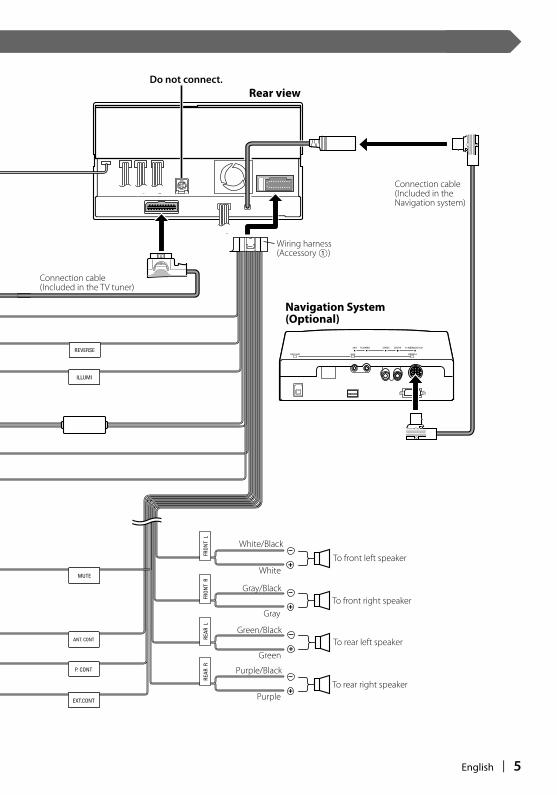
Connection cable (Included in the Navigation system)
Connection cable (Included in the TV tuner)
Wiring harness(Accessory 1)
To front left speaker
Rear view
Navigation System(Optional)
To front right speaker
To rear left speaker
To rear right speaker
White/Black
White
Gray/Black
Gray
Green/Black
Green
Purple
Purple/Black
Do not connect.
B54-4486_final.indd 5B54-4486_final.indd 5 06.9.14 5:18:36 PM06.9.14 5:18:36 PM
6 | English
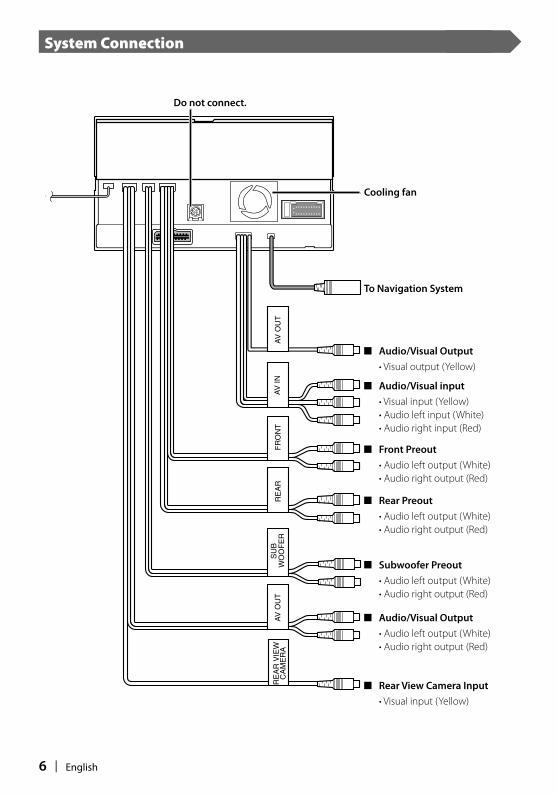
System Connection
■ Front Preout
• Audio left output (White)
• Audio right output (Red)
■ Rear Preout
• Audio left output (White)
• Audio right output (Red)
■ Subwoofer Preout
• Audio left output (White)
• Audio right output (Red)
■ Rear View Camera Input
• Visual input (Yellow)
■ Audio/Visual Output
• Audio left output (White)
• Audio right output (Red)
■ Audio/Visual input
• Visual input (Yellow)
• Audio left input (White)
• Audio right input (Red)
To Navigation System
■ Audio/Visual Output
• Visual output (Yellow)
Do not connect.
Cooling fan
B54-4486_final.indd 6B54-4486_final.indd 6 06.9.14 5:18:37 PM06.9.14 5:18:37 PM

English | 7
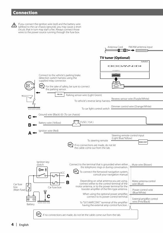
Installing the Escutcheon
Accessory 4
Cut out to meet the shape of the opening in the vehicle.
Cutting line
Accessory 4
Accessory 5
■ For General Motors
1. Cut out accessory 4 to meet the shape of the opening of the center console.
2. Attach accessory 4 to the unit.
■ For Toyota/Scion
1. Cut out accessory 4 as illustrated.
When cutting out accessory 4, make sure it fits the opening of the center console.
2. Fold double-sided adhesive (accessory 5) along the slit and attach it to accessory 4 cut-out against the center rib as illustrated. Use 2 pieces of accessory 5 for 1 accessory 4 cut-out.
3. Attach accessory 4 cut-out to the unit.
B54-4486_final.indd 7B54-4486_final.indd 7 06.9.14 5:18:38 PM06.9.14 5:18:38 PM
8 | English
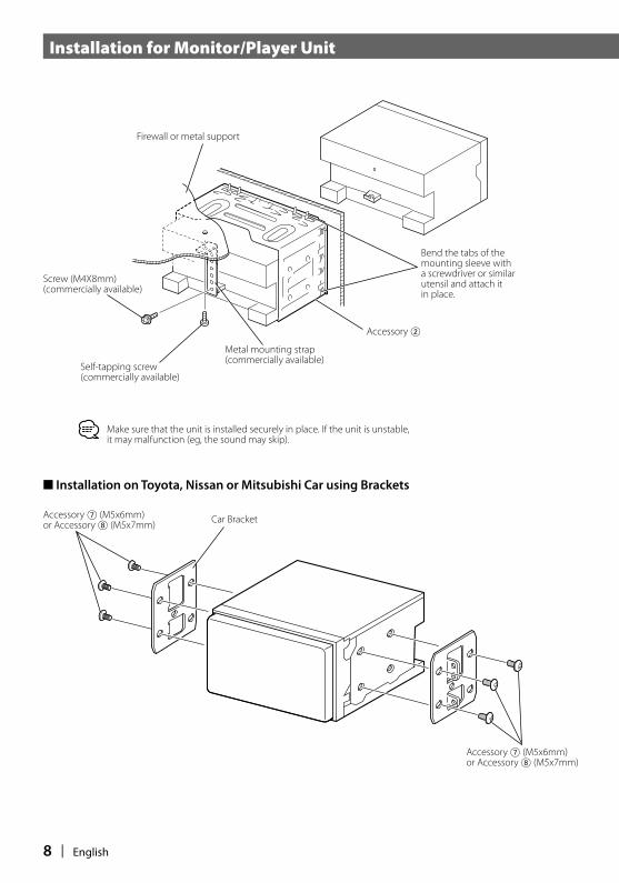
Accessory 2
Bend the tabs of the mounting sleeve with a screwdriver or similar utensil and attach it in place.
Metal mounting strap (commercially available)
Self-tapping screw (commercially available)
Screw (M4X8mm)(commercially available)
Make sure that the unit is installed securely in place. If the unit is unstable, it may malfunction (eg, the sound may skip).
Firewall or metal support
■ Installation on Toyota, Nissan or Mitsubishi Car using Brackets
Car BracketAccessory 7 (M5x6mm) or Accessory 8 (M5x7mm)
Accessory 7 (M5x6mm) or Accessory 8 (M5x7mm)
Installation for Monitor/Player Unit
B54-4486_final.indd 8B54-4486_final.indd 8 06.9.14 5:18:38 PM06.9.14 5:18:38 PM

English | 9
Be sure to eject the disc before installing or removing the unit. For how to eject the disc, see <Ejecting the Disc>.If you install, remove, or wire the unit with a disc loaded, the disc can get stuck in the unit.
■ Ejecting the disc
1. Open the panel
Press the [Panel Open/ Close] key.
2. Eject all the disc that are in the unit
Press the [EJECT] keys whose disc number indicators are lit.
3. Close the panel
Press the [Panel Open/ Close] key.
[Panel Open/ Close]
Never Install/Remove the Unit With a Disc Loaded
B54-4486_final.indd 9B54-4486_final.indd 9 06.9.14 5:18:39 PM06.9.14 5:18:39 PM

10 | English
Removing Monitor/Player Unit
■ Removing the Hard Rubber Frame (Accessory 6)
1. Engage the catch pins on the removal tool (accessory 3) and remove the two locks on the lower level.Lower the frame and pull it forward as shown in the figure.
2. When the lower level is removed, remove the upper two locations.
■ Removing the Unit
1. Remove the Hex-head screw with integral washer (M4 × 8mm) on the back panel.
2. Insert the two removal tools (accessory 3) deeply into the slots on each side, as shown.
3. Lower the removal tool toward the bottom, and pull out the unit halfway while pressing towards the inside.
4. Pull the unit all the way out with your hands, being careful not to drop it.
Be careful to avoid injury from the catch pins on the removal tool.
The frame can be removed from the top side in the same manner.
Removal Tool (Accessory 3)
Lock
Catch
Removal Tool (Accessory 3)
Before starting the work, make sure that no disc is loaded in the unit. See < Never Install/Remove the Unit With a Disc Loaded> (page 9).
B54-4486_final.indd 10B54-4486_final.indd 10 06.9.14 5:18:41 PM06.9.14 5:18:41 PM

B54-4486_final.indd 11B54-4486_final.indd 11 06.9.14 5:18:41 PM06.9.14 5:18:41 PM
12 | 中文(繁體字)
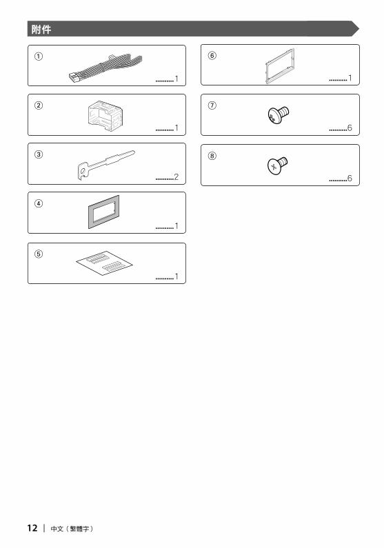
附件
1
..........1
2
..........1
3
..........2
4
..........1
5
..........1
6
..........1
7
..........6
8
..........6
B54-4486_CT r3.indd 12B54-4486_CT r3.indd 12 06.9.13 11:55:41 AM06.9.13 11:55:41 AM
中文(繁體字) | 13
安裝步驟
1. 為了防止發生短路,請拔出點火鑰匙,拆除蓄電池-極的連接。
2. 正確連接各裝置的輸入和輸出連接線。
3. 連接導線束的揚聲器導線。
4. 按照下列順序連接導線束:接地線、蓄電池導線、點火導線。
5. 將本機與導線束連接器連接。
6. 將本機安裝到汽車上。
7. 重新連接蓄電池的-極端子。
8. 按下復位按鈕。
2警告
‧ 如果將點火導線(紅色)和蓄電池導線(黃色)與汽車底盤(接地)連接,將可能造成短路而導致發生火災。請務必將這些導線透過保險絲盒與電源連接。
‧ 不得省略點火導線(紅色)和蓄電池導線(黃色)線路中的保險絲。電源必須透過保險絲與這些導線連接。
2注意
‧ 如果汽車的點火裝置不具備ACC位置,請將點火導線與可以由點火鑰匙接通和切斷的電源連接。如果將點火導線與始終接通的電源、即與蓄電池導線連接,蓄電池將全部消耗而無法使用。
‧ 如果控制台設有蓋板,應在安裝本機時注意避免在打開和關閉面板時與蓋板發生碰撞。
‧ 如果保險絲燒斷,應首先檢查有無發生短路,然後使用相同規格的保險絲更換舊保險絲。
‧ 使用膠帶或者其他絕緣材料對未連接的導線進行絕緣處理。不得取下未連接導線或者端子上的絕緣帽,防止發生短路。
‧ 將揚聲器導線與對應的端子正確連接。如果共用負極導線或與汽車的任何金屬部件連接進行接地處理,可能造成本機的損壞或發生故障。
‧ 如果僅兩個揚聲器與本系統連接,請或者均與前側輸出端子連接、或者均與後側輸出端子連接(不得混合連接在前側和後側)。例如,如果將左側揚聲器的+極端子與前側輸出端子連接,則不得將其-極端子與後側輸出端子連接。
‧ 完成本機安裝後,請檢查汽車的制動燈、方向燈、雨刷等是否工作正常。
‧ 本機的安裝角度不得超過30度。
‧ 本機設有冷卻風扇(第16頁)來降低內部的溫度。不得將本機安裝在該冷卻風扇受到阻礙的位置。阻礙風扇的排風出口將防礙內部溫度的降低而導致發生故障。
B54-4486_CT r3.indd 13B54-4486_CT r3.indd 13 06.9.13 11:55:42 AM06.9.13 11:55:42 AM

14 | 中文(繁體字)
連接方法
如果將點火導線(紅色)和蓄電池導線(黃色)與汽車底盤(接地)連接,將可能造成短路而導致發生火災。請務必將這些導線透過保險絲盒與電源連接。
天線導線 FM/AM天線輸入
使用隨機提供的接續連接器與汽車的停車制動器檢測開關線束連接。
與汽車的倒車燈線束連接
與汽車的照明控制開關連接
倒車傳感器導線(紫色/白色)
為了確保安全,請務必連接停車傳感器。
調光器控制導線(橙色/白色)
當使用選購的功率放大器時,與其功率控制端子連接。
與具備外部放大器控制功能的放大器 "EXT.AMP.CONT." 端子連接。
電視調諧器(選購)
停車傳感器導線(淡綠色)
蓄電池導線(黃色)
接地導線(黑色)-(與汽車底盤連接)
保險絲(15A)
點火導線(紅色)
電纜在不連接時不得露出。
操縱遙控器輸入(淡藍色/黃色)
與操縱遙控器連接
與當電話鈴響或在通話中時靜音的端子連接。
根據你所使用的天線種類,與電動天線的控制端子、或薄膜式天線的提昇
放大器的電源端子連接。
電纜在不連接時不得露出。
靜音導線(褐色)
電動天線控制導線(藍色)
功率控制導線(藍色/白色)
外部放大器控制導線(粉紅色/黑色)
關於與建伍導航系統的連接,請參照導航裝置的使用說明書。
點火鑰匙開關
ACC
汽車保險絲盒(總保險絲)
蓄電池
汽車保險絲盒
B54-4486_CT r3.indd 14B54-4486_CT r3.indd 14 06.9.13 11:55:43 AM06.9.13 11:55:43 AM

中文(繁體字) | 15
連接電纜(隨導航系統提供)
連接電纜(隨電視諧器提供)
導線束(附件1)
與前側左揚聲器連接
後視圖
導航系統(選購)
與前側右揚聲器連接
與後側左揚聲器連接
與後側右揚聲器連接
白色/黑色
白色
灰色/黑色
灰色
綠色/黑色
綠色
紫色
紫色/黑色
無連接。
B54-4486_CT r3.indd 15B54-4486_CT r3.indd 15 06.9.13 11:55:45 AM06.9.13 11:55:45 AM

16 | 中文(繁體字)
系統連接方法
■ 前側前級輸出
‧音頻左聲道輸出(白色)‧音頻右聲道輸出(紅色)
■ 後側前級輸出
‧音頻左聲道輸出(白色)‧音頻右聲道輸出(紅色)
■ 重低音前級輸出
‧音頻左聲道輸出(白色)‧音頻右聲道輸出(紅色)
■ 後視攝影機輸入
‧視頻輸入(黃色)
■ 音頻/視頻輸出
‧音頻左聲道輸出(白色)‧音頻右聲道輸出(紅色)
■ 音頻/視頻輸入
‧視頻輸入(黃色)‧音頻左聲道輸入(白色)‧音頻右聲道輸入(紅色)
與導航系統連接
■ 音頻/視頻輸出
‧視頻輸出(黃色)
無連接。
冷卻風扇
B54-4486_CT r3.indd 16B54-4486_CT r3.indd 16 06.9.13 11:55:46 AM06.9.13 11:55:46 AM
中文(繁體字) | 17
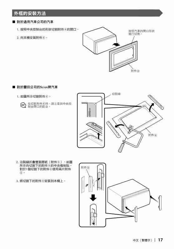
外框的安裝方法
附件4
按照汽車的開口形狀進行切割。
切割線
附件4
附件5
■ 對於通用汽車公司的汽車
1. 按照中央控制台的形狀切割附件4的開口。
2. 向本機安裝附件4。
■ 對於豐田公司的Scion牌汽車
1. 如圖所示切割附件4。
在切割附件4時,請注意與中央控制台開口的配合。
2. 沿裂縫折疊雙面膠紙(附件5),如圖所示向切割下的附件4的中央條粘貼。對於1個切割下的附件4使用兩片附件5。
3. 將切割下的附件4安裝到本機上。
B54-4486_CT r3.indd 17B54-4486_CT r3.indd 17 06.9.13 11:55:46 AM06.9.13 11:55:46 AM

18 | 中文(繁體字)
附件2
使用改錐或其他工具彎曲安裝套的鎖舌,然後進行安裝。
金屬安裝條(市售)
自攻螺絲(市售)
螺絲(M4×8mm)(市售)
請切實固定裝置。若安裝不穩,可能會出故障。(例如可能發生跳音等)。
隔熱板或金屬支撐
■ 使用支架對豐田、日產或三菱公司的汽車安裝
汽車安裝支架附件7(M5×6mm) 或者附件8(M5×7mm)
附件7(M5×6mm) 或者附件8(M5×7mm)
顯示器/播放裝置的安裝方法
B54-4486_CT r3.indd 18B54-4486_CT r3.indd 18 06.9.13 11:55:47 AM06.9.13 11:55:47 AM
中文(繁體字) | 19
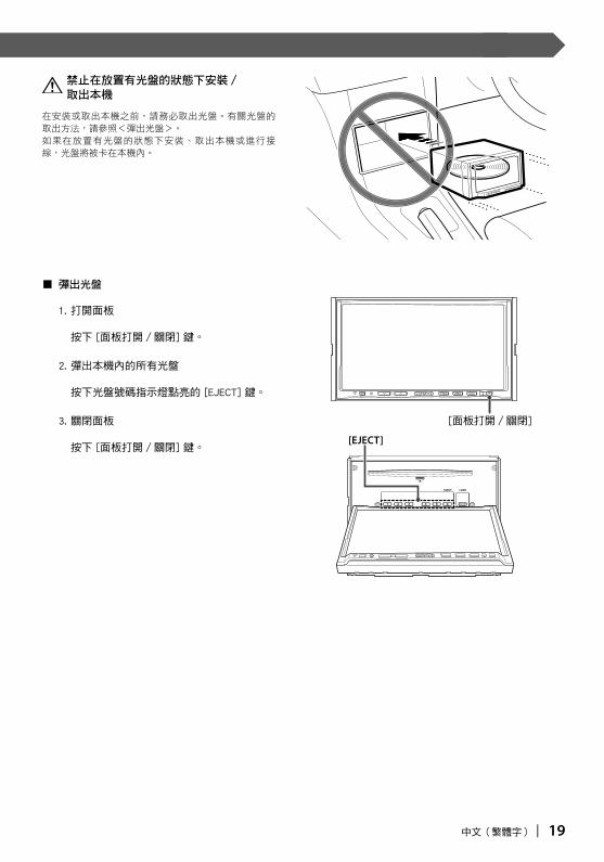
在安裝或取出本機之前,請務必取出光盤。有關光盤的取出方法,請參照<彈出光盤>。如果在放置有光盤的狀態下安裝、取出本機或進行接線,光盤將被卡在本機內。
■ 彈出光盤
1. 打開面板
按下 [面板打開/關閉] 鍵。
2. 彈出本機內的所有光盤
按下光盤號碼指示燈點亮的 [EJECT] 鍵。
3. 關閉面板
按下 [面板打開/關閉] 鍵。
[面板打開/關閉]
禁止在放置有光盤的狀態下安裝/取出本機
B54-4486_CT r3.indd 19B54-4486_CT r3.indd 19 06.9.13 11:55:48 AM06.9.13 11:55:48 AM

20 | 中文(繁體字)
顯示器/播放裝置的拆卸方法
■ 拆卸硬橡膠框(附件6)
1. 使用拆卸工具(附件3)的凸耳,拆除下側的兩處鎖定。按圖示要領下壓框架然後向前拉出。
2. 下側拆除後,拆除上側的兩處鎖定。
■ 本機的拆除方法
1. 卸下背面板上的附墊圈螺絲(M4×8mm)。
2. 如圖所示,將兩個拆卸工具(附件3)深深插入兩側槽內。
3. 將拆卸工具向下移動至底側,然後在壓向內側的同時將本機拉出到中途。
4. 用手將本機全部拉出,注意不要掉落。
請注意不要被拆卸工具的凸耳碰傷。
框架可以按照同樣的方法從上側開始拆除。
拆卸工具(附件3)
鎖定裝置凸耳
拆卸工具(附件3)
在開始作業之前,務必確認本機內不得放置有光盤。請參照< 禁止在放置有光盤的狀態下安裝/取出本機>(第19頁)。
B54-4486_CT r3.indd 20B54-4486_CT r3.indd 20 06.9.13 11:55:49 AM06.9.13 11:55:49 AM

B54-4486_CT r3.indd 21B54-4486_CT r3.indd 21 06.9.13 11:55:50 AM06.9.13 11:55:50 AM

22 | 한글
액세서리
1
..........1
2
..........1
3
..........2
4
..........1
5
..........1
6
..........1
7
..........6
8
..........6
B54-4486_Kor r2.1.indd 22B54-4486_Kor r2.1.indd 22 06.9.13 11:56:46 AM06.9.13 11:56:46 AM
한글 | 23
설치 절차
1. 누전을 방지하기 위해 시동 장치에서 키를 빼고 - 배터리를 분리하십시오.
2. 각 기기의 입력 및 출력 선을 올바르게 연결하십시오.
3. 배선 하네스의 스피커 선을 연결하십시오.
4. 배선 하네스의 선을 다음 순서로 연결하십시오. 접지, 배터리, 점화.
5. 기기의 배선 하네스 커넥터를 연결하십시오.
6. 차에 기기를 설치하십시오.
7. - 배터리를 다시 연결하십시오.
8. 리셋 버튼을 누르십시오.
2경고
ㆍ 점화 선(빨강)과 배터리 선(노랑)을 자동차 섀시(바닥)에 연결하면 누전을 일으켜 화재가 발생할 수 있습니다. 이 선을 항상 휴즈 단자를 통해 공급되는 전원에 연결하십시오.
ㆍ 휴즈를 점화 선(빨강)과 배터리 선(노랑)에서 자르지 마십시오. 전원 공급은 휴즈를 통해 선으로 연결되어야 합니다.
2주의
ㆍ 차량의 시동 장치에 ACC 위치가 없으면 시동 키로 켜고 끌 수 있도록 시동 선을 전원에 연결하십시오. 연속 전원을 공급하는 전원에 시동 선을 연결할 경우 배터리가 방전될 수도 있습니다.
ㆍ 콘솔에 뚜껑이 있는 경우 이 뚜껑을 열고 닫을 때 제품의 전면 플레이트에 손상이 가지 않도록 주의하여 설치하십시오.
ㆍ 휴즈가 끊어진 경우에는 먼저 배선이 누전된 원인을 찾고 나서 동급 휴즈로 교체하십시오.
ㆍ 연결되지 않은 선은 비닐 테이프나 이와 유사한 기타 물질로 절연시키십시오. 누전을 방지하기 위해 연결되지 않은 배선이나 단자의 끝에 씌워져 있는 캡을 제거하지 마십시오.
ㆍ 스피커 선을 해당하는 터미널에 올바르게 연결하십시오. - 선을 공용으로 사용하거나 차의 금속 부분에 닿게 되면 기기가 손상되거나 올바르게 작동하지 않을 수도 있습니다.
ㆍ 시스템에 두 개 스피커만 연결되어 있는 경우에는 커넥터를 두개의 앞쪽 출력 단자나 두 뛰쪽 출력 단자에 연결하십시오(앞쪽과 뒤쪽을 섞지 마십시오). 예를 들어, 왼쪽 스피커의 + 커넥터를 프론트 출력 단자에 연결하는 경우 - 커넥터를 뒤쪽 출력 단자에 연결하지 마십시오.
ㆍ 기기를 설치한 후에는 차량의 브레이크 램프, 방향등, 와이퍼 등이 올바르게 작동하는지 점검하십시오.
ㆍ 기기 설치 시 각도를 30° 이하로 설치하십시오.
ㆍ이 기기는 내부 온도를 낮추기 위해 냉각팬(26 페이지)이 있습니다. 이 기기를 이 기기의 냉각팬이 막힌 곳에 장착하지 마십시오. 이 곳을 막으면 내부 온도 냉각을 막아 제대로 기능을 할 수 없습니다.
B54-4486_Kor r2.1.indd 23B54-4486_Kor r2.1.indd 23 06.9.13 11:56:46 AM06.9.13 11:56:46 AM

24 | 한글
연결
시동 선(빨강)과 배터리 선(노랑)을 차량 섀시(접지)에 연결하는 경우 누전되어 화재가 발생할 수도 있습니다. 이 선을 항상 휴즈 단자를 통해 공급되는 전원에 연결하십시오.
안테나 코드 FM/AM 안테나 입력
제공된 연결 커넥터를 사용하여 자동차의 주차 브레이크 감지 스위치 하니스에 연결하십시오.
차량의 역 램프 하니스에
차량 조명 조정 스위치에
역 센서 선(자주/흰색)
안전을 위해 주차 센서를 반드시 연결하십시오.
디머 조정 선(주황/흰색)
파워 앰프(옵션)를 사용하는 경우에는 전원 조정 단자에 연결하십시오.
외부 앰프 제어 기능이 있는 앰프의 "EXT.AMP.CONT" 단자에.
TV 튜너(옵션)
주차 센서 선(연녹색)
배터리 선(노랑)
접지 선(검정) - (차량 섀시에)
휴즈(15A)
시동 선I(빨강)
연결이 안되면 케이블을 탭에서 나오게 하지 마십시오.
원격 제어 입력 조정(연청/노랑)
원격 조정에
전화가 울리거나 대화중에 접지되는 단자에 연결하십시오.
사용하는 안테나에 따라, 자동차 안테나의 제어 단자나 필름형 안테나의 부스
터 증폭기 전원 단자에 연결하십시오.
연결이 안되면 케이블을 탭에서 나오게 하지 마십시오.
무음 선(갈색)
자동차 안테나 제어선(청색)
전원 제어 선 (청색/흰색)
외부 증폭기 제어 선(분홍/검정)
Kenwood 내비게이션 시스템을 연결하려면 네비게이션 설명서를 참조하십시오.
점화 키 스위치
ACC
자동차휴즈박스 (주 휴즈)
배터리
차량 휴즈 단자
B54-4486_Kor r2.1.indd 24B54-4486_Kor r2.1.indd 24 06.9.13 11:56:47 AM06.9.13 11:56:47 AM
한글 | 25
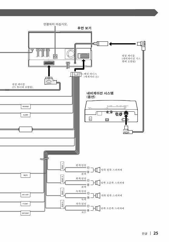
연결 케이블 (내비게이션 시스템에 포함됨)
연결 케이블 (TV 튜너에 포함됨)
배선 하니스(액세서리 1)
앞쪽 왼쪽 스피커에
후면 보기
내비게이션 시스템(옵션)
앞쪽 오른쪽 스피커에
뒤쪽 왼쪽 스피커에
뒤쪽 오른쪽 스피커에
흰색/검정
흰색
회색/검정
회색
녹색/검정
녹색
자주
자주/검정
연결하지 마십시오.
B54-4486_Kor r2.1.indd 25B54-4486_Kor r2.1.indd 25 06.9.13 11:56:48 AM06.9.13 11:56:48 AM

26 | 한글
시스템 연결
■ 앞쪽 프리아웃
ㆍ오디오 왼쪽 출력(흰색)
ㆍ오디오 오른쪽 출력(빨강)
■ 뒤쪽 프리아웃
ㆍ오디오 왼쪽 출력(흰색)
ㆍ오디오 오른쪽 츨력(빨강)
■ 서브우퍼 프리아웃
ㆍ 오디오 왼쪽 출력(흰색)
ㆍ 오디오 오른쪽 출력(빨강)
■ 후면 보기 카메라 입력
ㆍ시각 입력(노랑)
■ 오디오/시각 출력
ㆍ오디오 왼쪽 출력(흰색)
ㆍ오디오 오른쪽 출력(빨강)
■ 오디오/시각 입력
ㆍ시각 입력(노랑)
ㆍ오디오 왼쪽 입력(흰색)
ㆍ오디오 오른쪽 입력(빨강)
내비게이션 시스템에
■ 오디오/시각 출력
ㆍ시각 출력(노랑)
연결하지 마십시오.
냉각 팬
B54-4486_Kor r2.1.indd 26B54-4486_Kor r2.1.indd 26 06.9.13 11:56:48 AM06.9.13 11:56:48 AM
한글 | 27
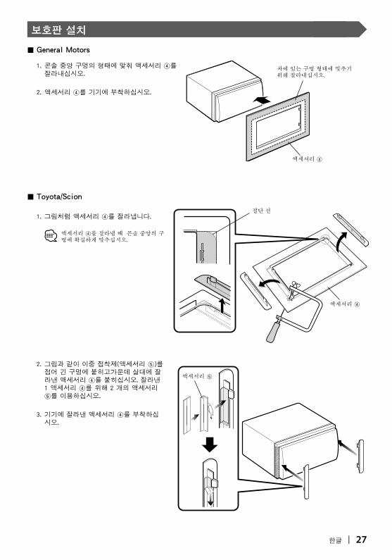
보호판 설치
액세서리 4
차에 있는 구멍 형태에 맞추기 위해 잘라내십시오.
절단 선
액세서리 4
액세서리 5
■ General Motors
1. 콘솔 중앙 구멍의 형태에 맞춰 액세서리 4를 잘라내십시오.
2. 액세서리 4를 기기에 부착하십시오.
■ Toyota/Scion
1. 그림처럼 액세서리 4를 잘라냅니다.
액세서리 4를 잘라낼 때 콘솔 중앙의 구멍에 확실하게 맞추십시오.
2. 그림과 같이 이중 접착제(액세서리 5)를 접어 긴 구멍에 붙히고가운데 살대에 잘라낸 액세서리 4를 붙히십시오. 잘라낸 1 액세서리 4를 위해 2 개의 액세서리 5를 이용하십시오.
3. 기기에 잘라낸 액세서리 4를 부착하십시오.
B54-4486_Kor r2.1.indd 27B54-4486_Kor r2.1.indd 27 06.9.13 11:56:49 AM06.9.13 11:56:49 AM

28 | 한글
액세서리 2
장착 슬리브의 탭을 나사드라이버로 또느 비슷한 기구로 구부려 제 위치에 부착하십시오.
금속 장착 띠 (시중에서 구입 가능)
자가탭핑 나사 (시중에서 구입 가능)
나사(M4×8mm)(시중에서 구입 가능)
기기가 제자리에 안전하게 장착되는지 확인하십시오. 이 기기가 불안정하면 제대로 작동하지 않을 수 있습니다(예, 소리가 넘어갈 수 있습니다).
방화벽 또는 금속 지지대
■ 브래킷으로 Toyota, Nissan 또는 Mitsubishi 승용차에 설치
승용차 브래킷액세서리 7(M5×6mm) 또는 액세서리 8(M5×7mm)
액세서리 7(M5×6mm)또는 액세서리 8(M5×7mm)
모니터/플레이어 기기 설치
B54-4486_Kor r2.1.indd 28B54-4486_Kor r2.1.indd 28 06.9.13 11:56:49 AM06.9.13 11:56:49 AM
한글 | 29
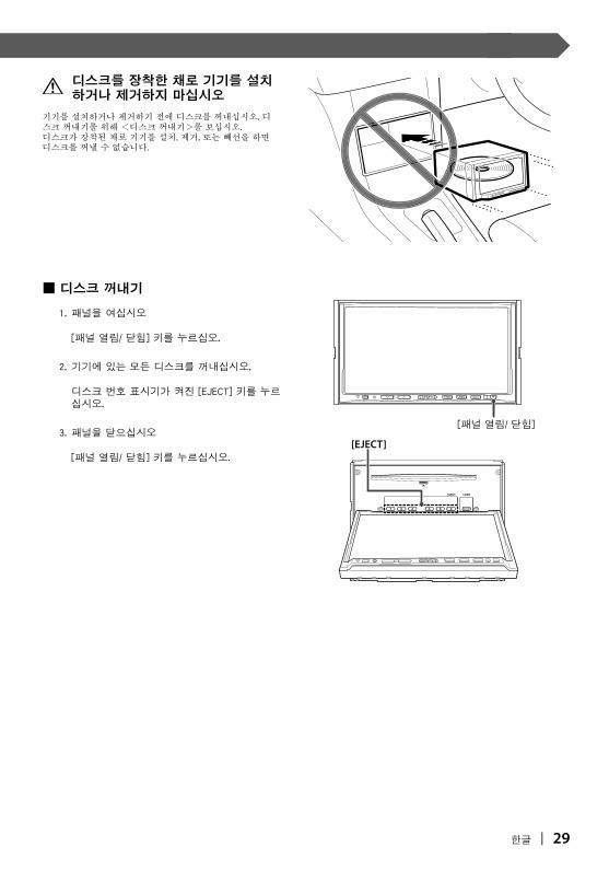
기기를 설치하거나 제거하기 전에 디스크를 꺼내십시오. 디스크 꺼내기를 위해 <디스크 꺼내기>를 보십시오.디스크가 장착된 채로 기기를 설치, 제거, 또는 빼선을 하면 디스크를 꺼낼 수 없습니다.
■ 디스크 꺼내기
1. 패널을 여십시오
[패널 열림/ 닫힘] 키를 누르십오.
2. 기기에 있는 모든 디스크를 꺼내십시오.
디스크 번호 표시기가 켜진 [EJECT] 키를 누르십시오.
3. 패널을 닫으십시오
[패널 열림/ 닫힘] 키를 누르십시오.
[패널 열림/ 닫힘]
디스크를 장착한 채로 기기를 설치하거나 제거하지 마십시오
B54-4486_Kor r2.1.indd 29B54-4486_Kor r2.1.indd 29 06.9.13 11:56:50 AM06.9.13 11:56:50 AM

30 | 한글
모니터/플레이어 기기 제거하기
■ 단단한 고무 프레임 제거하기(액세서리 6)
1. 캐치 핀을 제거 도구에 대고(액세서리 3) 아래쪽에 두개의 락을 제거하십시오.틀을 낮추고 그림에 보인 것처럼 앞으로 당기십시오.
2. 아래쪽이 제거되면 윗쪽 두곳을 제거하십시오.
■ 기기 제거하기
1. 뒷 패널에서 내부 와셔와 함께 있는 6각 나사를(M4×8mm) 제거하십시오.
2. 두개의 제거 도구 (액세서리 3)를 보여진 것처럼 각각의 슬롯에 깊히 삽입하십시오.
3. 제거 도구를 아래쪽으로 낮추고 내부를 앞쪽으로 밀면서 기기를 빼십시오.
4. 떨어뜨리지 않도록 주의하면서 기기를 손으로 끝까지 당기십시오.
제거 도구에 캐치 핀으로부터 부상을 피하도록 주의하십시오.
같은 방식으로 틀을 윗쪽에서 제거할 수 있습니다.
제거 도구(액세서리 3)
잠금장치
캐치
제거 도구(액세서리 3)
시작하기 전에 기기에 디스키가 없는지 확인하십시오. < 디스크가 장착된 채로 설치/제거하지 마십시오> (29 페이지) 참조.
B54-4486_Kor r2.1.indd 30B54-4486_Kor r2.1.indd 30 06.9.13 11:56:51 AM06.9.13 11:56:51 AM

B54-4486_Kor r2.1.indd 31B54-4486_Kor r2.1.indd 31 06.9.13 11:56:52 AM06.9.13 11:56:52 AM

B54-4486_Kor r2.1.indd 32B54-4486_Kor r2.1.indd 32 06.9.13 11:56:52 AM06.9.13 11:56:52 AM