Dynamic Positioning Systems– Usability and Interaction Styles
10
Dynamic Positioning Systems– Usability and Interaction Styles Frøy Birte Bjørneseth University of Strathclyde Rolls-Royce Marine AS [email protected] Mark D. Dunlop University of Strathclyde [email protected] Jann Peter Strand Rolls-Royce Marine AS [email protected] ABSTRACT This paper describes the first steps of a research project directed towards human computer interaction (HCI) within the maritime environment and on maritime equipment. The focus is at this stage mainly on interaction with Dynamic Positioning Systems (DP) and how new interaction styles can be introduced to make the interaction more efficient and less faulty in both standard operations and in safety-critical situations. The initial experiment looks into how a DP operator can operate a DP system by using bi-manual interaction/multi-touch combined with hand-gestures to create a new type of user-experience. The aim for this research is to investigate which gestures feel natural to the DP operator and how/if they can be implemented into a real-life DP system. Categories and Subject Descriptors H.5.2 [Information interfaces and presentation]: User Interfaces – Interaction Styles, Human Factors, Input devices and strategies. General Terms Design, Experimentation, Security, Human Factors Keywords Dynamic Positioning, Maritime Environment, Bi-manual Interaction, Multi-Touch, Gestures, Graphical User Interface, Safety Critical situations 1. INTRODUCTION In the late 1960’s and early 1970’s the demand for petroleum related products increased and the petroleum industry started offshore- drilling in search of larger deposits of oil. With this, a new generation of vessels emerged, which was fitted with equipment adapted to the offshore industry, and also had the ability to provide oil platforms with needed supplies. New requirements appeared with new operations and anchor handling-, supply-, seismic- and cable lying - vessels, amongst others, were designed to support the offshore petroleum industry. When drilling commenced in deep-sea areas, the usage of traditional anchors to maintain position was no longer possible. Vessels were in the beginning, held in the right position manually by manipulating the propulsion system, which included different types of thrusters and propellers. This was a risky operation and vulnerable to human errors. This has lead onto the invention of the first Dynamic Positioning Systems. 2. BACKGROUND AND RELATED WORK 2.1 Dynamic Positioning (DP) To keep the vessel in a fixed position, a system was developed which automatically compensated to natural forces such as waves, wind and current. This is called a Dynamic Positioning system (DP) and its technology has developed from the first simple systems in the 1960’s to today’s advanced systems covering single, double and triple redundancy according to the operation’s safety critical level. A Dynamic Positioning system (DP) can be defined as: -A computer controlled system to automatically maintain a ship’s position and heading by using her own propellers and thrusters. A DP system [4] can be seen as a complete system that includes operator stations, position reference sensors, gyro compasses (detects true north by using an electrically powered fast spinning wheel and friction forces, in order to exploit the rotation of the earth), and a range of different sensors that give feedback to the operator about the ship’s position and the forces that influence the its direction. A vessel has 6 degrees of freedom (DOF) (see figure 1), which enables it to move around three axis, x-, y-, and z-axis. The DP system is only concerned with manipulating three degrees of freedom, surge, sway and yaw. In non- maritime terms these DOFs can be translated to forward/backward- , left/right- and a rotation movement where the vessel can rotate both clockwise and counter clockwise around its own axis. In addition there are the movements that correspond to up/down, rolling from side to side and pitching that happen, for example, when the vessel meets a wave. Figure 1: A vessel’s 6 Degrees of Freedom (DOF) Permission to make digital or hard copies of all or part of this work for personal or classroom use is granted without fee provided that copies are not made or distributed for profit or commercial advantage and that copies bear this notice and the full citation on the first page. To copy otherwise, or republish, to post on servers or to redistribute to lists, requires prior specific permission and/or a fee. NordiCHI 2008: Using Bridges, 18-22 October, Lund, Sweden Copyright 2008 ACM ISBN 978-1-59593-704-9. $5.00
Transcript of Dynamic Positioning Systems– Usability and Interaction Styles
Dynamic Positioning Systems–
Usability and Interaction StylesFrøy Birte Bjørneseth University of Strathclyde Rolls-Royce Marine AS
Mark D. Dunlop University of Strathclyde
Jann Peter Strand Rolls-Royce Marine AS
ABSTRACT
This paper describes the first steps of a research project directed towards human computer interaction (HCI) within the maritime environment and on maritime equipment. The focus is at this stage mainly on interaction with Dynamic Positioning Systems (DP) and how new interaction styles can be introduced to make the interaction more efficient and less faulty in both standard operations and in safety-critical situations. The initial experiment looks into how a DP operator can operate a DP system by using bi-manual interaction/multi-touch combined with hand-gestures to create a new type of user-experience. The aim for this research is to investigate which gestures feel natural to the DP operator and how/if they can be implemented into a real-life DP system.
Categories and Subject Descriptors
H.5.2 [Information interfaces and presentation]: User Interfaces – Interaction Styles, Human Factors, Input devices and strategies.
General Terms
Design, Experimentation, Security, Human Factors
Keywords
Dynamic Positioning, Maritime Environment, Bi-manual Interaction, Multi-Touch, Gestures, Graphical User Interface, Safety Critical situations
1. INTRODUCTION In the late 1960’s and early 1970’s the demand for petroleum related products increased and the petroleum industry started offshore- drilling in search of larger deposits of oil. With this, a new generation of vessels emerged, which was fitted with equipment adapted to the offshore industry, and also had the ability to provide oil platforms with needed supplies. New requirements appeared with new operations and anchor handling-, supply-, seismic- and cable lying - vessels, amongst others, were designed to support the offshore petroleum industry.
When drilling commenced in deep-sea areas, the usage of traditional anchors to maintain position was no longer possible. Vessels were in the beginning, held in the right position manually
by manipulating the propulsion system, which included different types of thrusters and propellers. This was a risky operation and vulnerable to human errors. This has lead onto the invention of the first Dynamic Positioning Systems.
2. BACKGROUND AND RELATED WORK
2.1 Dynamic Positioning (DP) To keep the vessel in a fixed position, a system was developed which automatically compensated to natural forces such as waves, wind and current. This is called a Dynamic Positioning system (DP) and its technology has developed from the first simple systems in the 1960’s to today’s advanced systems covering single, double and triple redundancy according to the operation’s safety critical level.
A Dynamic Positioning system (DP) can be defined as:
-A computer controlled system to automatically maintain a ship’s
position and heading by using her own propellers and thrusters.
A DP system [4] can be seen as a complete system that includes operator stations, position reference sensors, gyro compasses (detects true north by using an electrically powered fast spinning wheel and friction forces, in order to exploit the rotation of the earth), and a range of different sensors that give feedback to the operator about the ship’s position and the forces that influence the its direction.
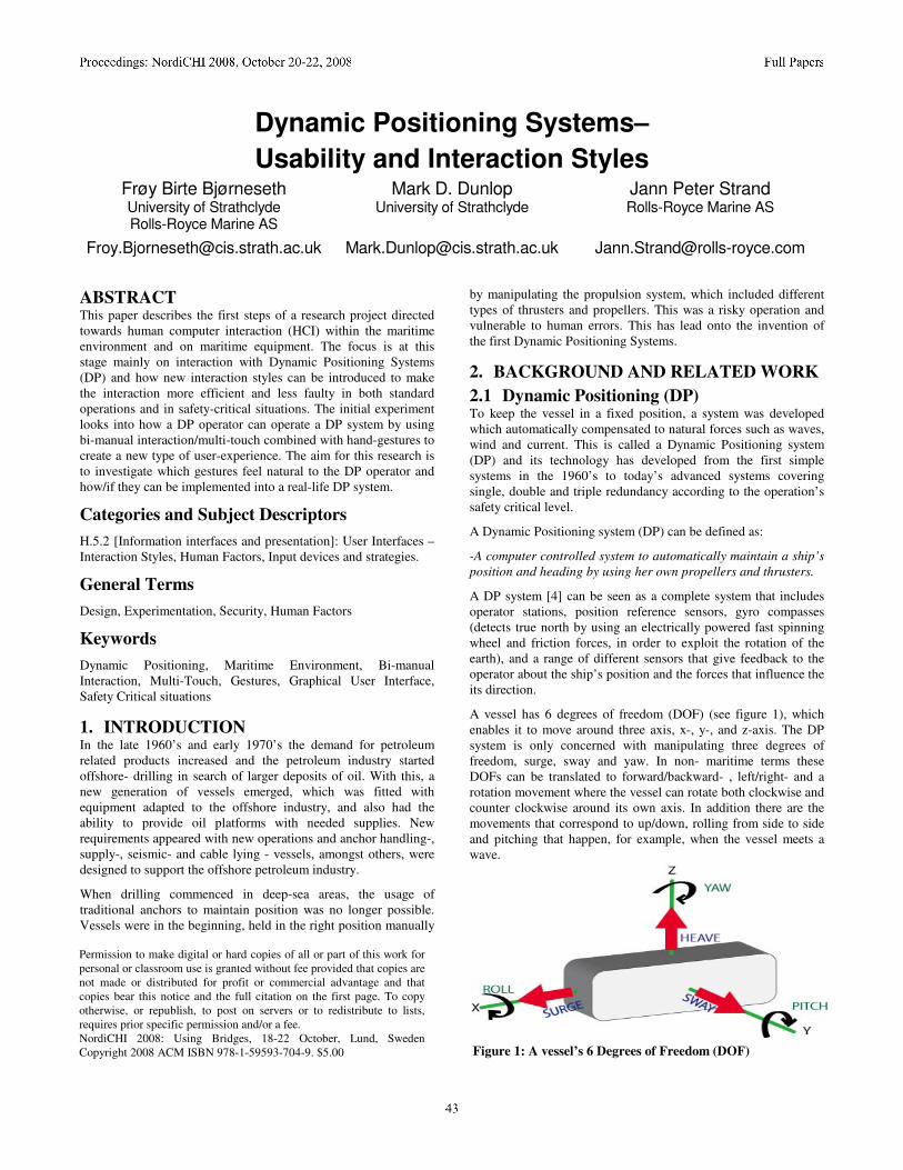
A vessel has 6 degrees of freedom (DOF) (see figure 1), which enables it to move around three axis, x-, y-, and z-axis. The DP system is only concerned with manipulating three degrees of freedom, surge, sway and yaw. In non- maritime terms these DOFs can be translated to forward/backward- , left/right- and a rotation movement where the vessel can rotate both clockwise and counter clockwise around its own axis. In addition there are the movements that correspond to up/down, rolling from side to side and pitching that happen, for example, when the vessel meets a wave.
Figure 1: A vessel’s 6 Degrees of Freedom (DOF)
Permission to make digital or hard copies of all or part of this work for personal or classroom use is granted without fee provided that copies are not made or distributed for profit or commercial advantage and that copies bear this notice and the full citation on the first page. To copy otherwise, or republish, to post on servers or to redistribute to lists, requires prior specific permission and/or a fee. NordiCHI 2008: Using Bridges, 18-22 October, Lund, Sweden Copyright 2008 ACM ISBN 978-1-59593-704-9. $5.00
The three DOF’s available in the DP system enables the operator to manipulate the ship so the DP system can carry out its main task, to maintain position and heading. The DP operator assists the system by inputting setpoint values, which are measured to obtain feedback values from the system. By obtaining the feedback values from the sensors available, the vessel can be manipulated in an accurate manner. The vessel’s position is determined by information received from the position reference system and/or the navigation system. The heading is determined with information gained from one or more gyrocompasses situated in the lower levels of the vessel’s hull.
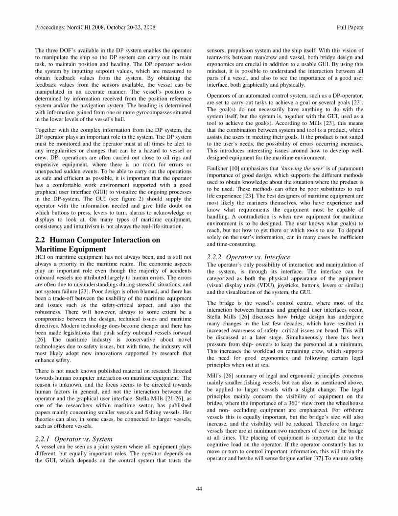
Together with the complex information from the DP system, the DP operator plays an important role in the system. The DP system must be monitored and the operator must at all times be alert to any irregularities or changes that can be a hazard to vessel or crew. DP- operations are often carried out close to oil rigs and expensive equipment, where there is no room for errors or unexpected sudden events. To be able to carry out the operations as safe and efficient as possible, it is important that the operator has a comfortable work environment supported with a good graphical user interface (GUI) to visualize the ongoing processes in the DP-system. The GUI (see figure 2) should supply the operator with the information needed and give little doubt on which buttons to press, levers to turn, alarms to acknowledge or displays to look at. On many types of maritime equipment, consistency and intuitivism is not always the real-life situation.
2.2 Human Computer Interaction on
Maritime Equipment HCI on maritime equipment has not always been, and is still not always a priority in the maritime realm. The economic aspects play an important role even though the majority of accidents onboard vessels are attributed largely to human errors. The errors are often due to misunderstandings during stressful situations, and not system failure [23]. Poor design is often blamed, and there has been a trade-off between the usability of the maritime equipment and issues such as the safety-critical aspect, and also the robustness. There will however, always to some extent be a compromise between the design, technical issues and maritime directives. Modern technology does become cheaper and there has been made legislations that push safety onboard vessels forward [26]. The maritime industry is conservative about novel technologies due to safety issues, but with time, the industry will most likely adopt new innovations supported by research that enhance safety.
There is not much known published material on research directed towards human computer interaction on maritime equipment. The reason is unknown, and the focus seems to be directed towards human factors in general, and not the interaction between the operator and the graphical user interface. Stella Mills [21-26], as one of the researchers within maritime sector, has published papers mainly concerning smaller vessels and fishing vessels. Her theories can also, in some cases, be connected to larger vessels, such as offshore vessels.
2.2.1 Operator vs. System A vessel can be seen as a joint system where all equipment plays different, but equally important roles. The operator depends on the GUI, which depends on the control system that trusts the
sensors, propulsion system and the ship itself. With this vision of teamwork between man/crew and vessel, both bridge design and ergonomics are crucial in addition to a usable GUI. By using this mindset, it is possible to understand the interaction between all parts of a vessel, and also to see the importance of a good user interface, both graphically and physically.
Operators of an automated control system, such as a DP-operator, are set to carry out tasks to achieve a goal or several goals [23]. The goal(s) do not necessarily have anything to do with the system itself, but the system is, together with the GUI, used as a tool to achieve the goal(s). According to Mills [23], this means that the combination between system and tool is a product, which assists the users in meeting their goals. If the product is not suited to the user’s needs, the possibility of errors occurring increases. This introduces interesting issues around how to develop well- designed equipment for the maritime environment.
Faulkner [10] emphasizes that ‘knowing the user’ is of paramount importance of good design, which supports the different methods used to obtain knowledge about the situation where the product is to be used. These methods can often be poor substitutes to real life experience [23]. The best designers of maritime equipment are most likely the mariners themselves, who have experience and know what requirements the equipment must be capable of handling. A contradiction is when new equipment for maritime environment is to be designed. The user knows what goal(s) to reach, but not how to get there or which tools to use. To depend solely on the user’s information, can in many cases be inefficient and time-consuming.
2.2.2 Operator vs. Interface The operator’s only possibility of interaction and manipulation of the system, is through its interface. The interface can be categorized as both the physical appearance of the equipment (visual display units (VDU), joysticks, buttons, levers or similar) and the visualization of the system, the GUI.
The bridge is the vessel’s control centre, where most of the interaction between humans and graphical user interfaces occur. Stella Mills [26] discusses how bridge design has undergone many changes in the last few decades, which have resulted in increased awareness of safety- critical issues on board. This will be discussed at a later stage. Simultaneously there has been pressure from ship- owners to keep the personnel at a minimum. This increases the workload on remaining crew, which supports the need for good ergonomics and following certain legal principles when out at sea.
Mill’s [26] summary of legal and ergonomic principles concerns mainly smaller fishing vessels, but can also, as mentioned above, be applied to larger vessels with a slight change. The legal principles mainly concern the visibility of equipment on the bridge, where the importance of a 360° view from the wheelhouse and non- occluding equipment are emphasized. For offshore vessels this is equally important, but the bridge’s size will also increase, and the visibility will be reduced. Therefore on larger vessels there are at minimum two members of crew on the bridge at all times. The placing of equipment is important due to the cognitive load on the operator. If the operator constantly has to move or turn to control important information, this will strain the operator and he/she will sense fatigue earlier [37].To ensure safety
onboard, it is vital that the operators of the vessel are comfortable and not put under any extra strain.
The ergonomic principles [26] deal with, once again visibility, but also computer related tasks. On larger vessels, such as offshore vessels, it is highly important to the operator, that he/she is presented with only the information needed. Excessive information increases workload, which can lead to the operator making the wrong decisions and again unsafe operation of the vessel. It is therefore important that the information presented to the operator on the different VDU’s, is grouped. Related information should be placed together and information with similar appearance that handles different tasks should be placed apart, to avoid misreading of the information. This principle applies to all equipment to minimize faulty decisions and misunderstandings. Lazet and Schuffel [18] emphasize that with too much visual information, critical information may be lost because of inattention, or simply because the operator is not looking in the right direction. This means that when decisions are to be made by interpretation of displayed information, the presentation of data is highly important. However the most important task when discussing bridge/wheelhouse design is consistency, both concerning software and hardware. Consistency is the keyword that enables humans to recognize patterns and situations that are similar. By recognizing resemblance, the operator can act by using the knowledge the brain already holds.
2.2.2.1 Presenting Information in GUI’s A GUI consists of different components. In a DP system, there will typically be a main overview where a graphical illustration of the vessel is visible. In addition, other relevant information is placed in menus or similar, on each side and top/bottom of the display. The component’s composition is crucial to the overall operator vs. interface experience.
Figure 2. Rolls- Royce (RR) DP GUI
The symbols should be crystal clear with only one purpose and meaning [24] that is not possible to misunderstand. Colors should be consistent, and the same should the composition of the components be. It is considered an advantage if the operator can be presented to a 3D visualization [25], where the designer has assurance that the objects are easy to learn, recognizable and realistic [24].
Colors are often misused. Powerful colors, which is naturally connected with danger or i.e. STOP, such as red, should not be used for other purposes than actions related to the ones mentioned above. In a DP system, it is crucial that the colors support division
between different states on vital parts of the system. The colors red and green also correspond to the lanterns on the vessel, which symbolizes port or starboard, and are often used in maritime GUIs to illustrate left or right. Red and green can therefore be difficult to use due to the dual meaning, and shades of similar colors are often used instead. This is important to take into account when designing GUI’s for maritime equipment, in addition to taking advantage of the operator’s previous knowledge [25] when designing the GUI. This can improve the design and ease the cognitive load on the operator.
A problem the operator can encounter while using modern maritime equipment, is loss of control of the system [24]. This work against the GUI’s purpose and according to Dix, Finlay, Abowd and Beale [8], who mention an example from the Apple Guidelines which refers to user control:
The user, not the computer, initiates and controls all actions.
If the user has lost his/her feeling of control, the operator will experience stress and insecurity, which dangers the operation. Leaving the user in control can be a design challenge. A solution can be to follow Norman’s Stages of Action as Design Aids [29] that suggests a checklist, where visibility, a good conceptual model, good mappings and feedback to the user are assuring steps of design, leading in the right direction.
There are, in addition, other issues concerning bridge design, which is outside the scope of this paper, such as information integration [24, 25] and centralization of equipment.
2.2.3 Interface vs. Safety Critical Situations Safety at sea is of utter importance when operating large vessels close to oilrigs and other offshore installations. Accidents considered small-scaled can cause abortion of operations and cost large sums of money. When accidents become large-scale, life of crew and vessel is at danger. In many cases “human error” is concluded as the fatal cause of the accident, or a factor in a series of unfortunate events. To minimize the frequency of human errors, usable equipment is, as mentioned above, the key issue. Most of the time it is not the user’s fault, poor design is often the sinner [29]. Wendy MacKay [38] emphasizes that the design of safety-critical systems differs from that of other interactive systems: while improving productivity is important, safety remains the overriding concern. Increasing the former at the expense of the latter is simply not acceptable. Every year numerous false alarms [21] sound at rescue centers based in maritime nations, which calls for a lot of resources. In order to find a solution to false alarms, i.e. slips caused by misunderstandings and stress-related issues, the composition of the different types of equipment, where it’s placed on the bridge according to the operator(s) and if the GUI is suitable for its purpose must be investigated. In a safety critical situation a button press- combination can be hard to remember [23]. The human mind gets clouded by fear of an impending accident. Depending on how critical the situation is, our mind starts re- organizing our senses, some are sharpened and others are paralyzed and put on hold. Irrational behavior occurs when something unexpected happens1. On board a vessel, the
1 http://www.betterhealth.vic.gov.au/bhcv2/bhcarticles.nsf/pages/
Trauma_how_our_body_reacts?Open Accessed: 12.08.2008
consequences of such behavior are at a much higher level than on shore. This is why a clear menu structure [27], grouping of equipment related to the same functions and correct usage of colors, amongst others, is of such importance. Under extreme stress, an experienced user mirrors the behavior of a novice or less experienced user. A clear and concise system will bring the operator back in his/her position as an experienced user [31].
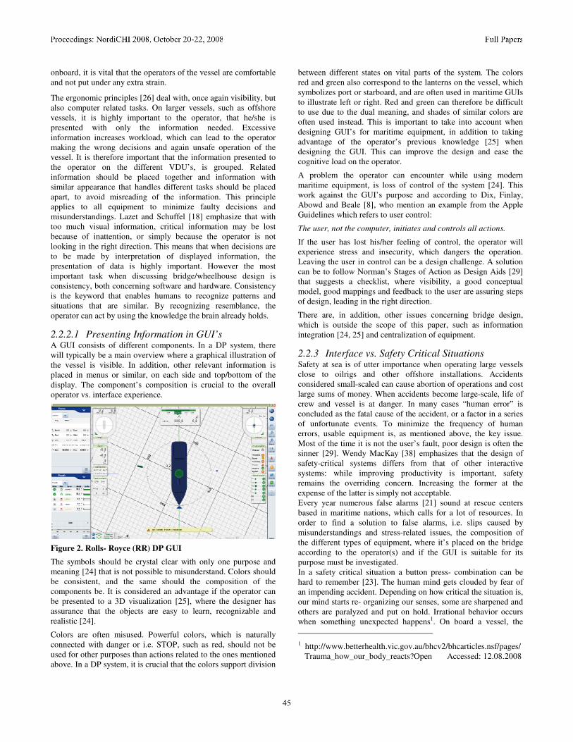
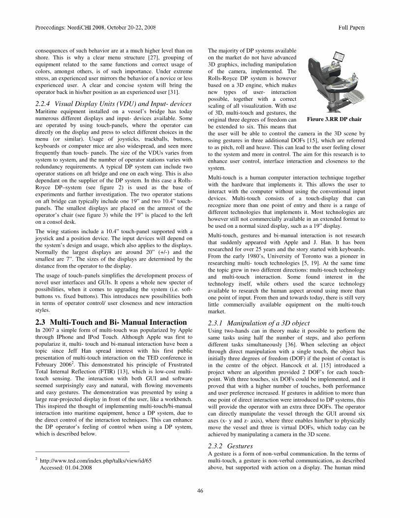
2.2.4 Visual Display Units (VDU) and Input- devices Maritime equipment installed on a vessel’s bridge has today numerous different displays and input- devices available. Some are operated by using touch-panels, where the operator can directly on the display and press to select different choices in the menu (or similar). Usage of joysticks, trackballs, buttons, keyboards or computer mice are also widespread, and seen more frequently than touch- panels. The size of the VDUs varies from system to system, and the number of operator stations varies with redundancy requirements. A typical DP system can include two operator stations on aft bridge and one on each wing. This is also dependant on the supplier of the DP system. In this case a Rolls- Royce DP–system (see figure 2) is used as the base of experiments and further investigation. The two operator stations on aft bridge can typically include one 19” and two 10.4” touch- panels. The smallest displays are placed on the armrest of the operator’s chair (see figure 3) while the 19” is placed to the left on a consol desk.
The wing stations include a 10.4” touch-panel supported with a joystick and a position device. The input devices will depend on the system’s design and usage, which also applies to the displays. Normally the largest displays are around 20” (+/-) and the smallest are 7”. The sizes of the displays are determined by the distance from the operator to the display.
The usage of touch–panels simplifies the development process of novel user interfaces and GUIs. It opens a whole new specter of possibilities, when it comes to upgrading the system (i.e. soft-buttons vs. fixed buttons). This introduces new possibilities both in terms of operator control/ user closeness and new interaction styles.
2.3 Multi-Touch and Bi- Manual Interaction In 2007 a simple form of multi-touch was popularized by Apple through IPhone and IPod Touch. Although Apple was first to popularize it, multi- touch and bi-manual interaction have been a topic since Jeff Han spread interest with his first public presentation of multi-touch interaction on the TED conference in February 20062. This demonstrated his principle of Frustrated Total Internal Reflection (FTIR) [13], which is low-cost multi-touch sensing. The interaction with both GUI and software seemed surprisingly easy and natural, with flowing movements and easy gestures. The demonstration was presented by using a large rear-projected display in front of the user, like a workbench. This inspired the thought of implementing multi-touch/bi-manual interaction into maritime equipment, hence a DP system, due to the direct control of the interaction techniques. This can enhance the DP operator’s feeling of control when using a DP system, which is described below.
2 http://www.ted.com/index.php/talks/view/id/65
Accessed: 01.04.2008
The majority of DP systems available on the market do not have advanced 3D graphics, including manipulation of the camera, implemented. The Rolls-Royce DP system is however based on a 3D engine, which makes new types of user- interaction possible, together with a correct scaling of all visualization. With use of 3D, multi-touch and gestures, the original three degrees of freedom can be extended to six. This means that the user will be able to control the camera in the 3D scene by using gestures in three additional DOFs [15], which are referred to as pitch, roll and heave. This can lead to the user feeling closer to the system and more in control. The aim for this research is to enhance user control, interface interaction and closeness to the system.
Multi-touch is a human computer interaction technique together with the hardware that implements it. This allows the user to interact with the computer without using the conventional input devices. Multi-touch consists of a touch-display that can recognize more than one point of entry and there is a range of different technologies that implements it. Most technologies are however still not commercially available in an extended format to be used on a normal sized display, such as a 19” display.
Multi-touch, gestures and bi-manual interaction is not research that suddenly appeared with Apple and J. Han. It has been researched for over 25 years and the story started with keyboards. From the early 1980’s, University of Toronto was a pioneer in researching multi- touch technologies [5, 19]. At the same time the topic grew in two different directions: multi-touch technology and multi-touch interaction. Some found interest in the technology itself, while others used the scarce technology available to research the human aspect around using more than one point of input. From then and towards today, there is still very little commercially available equipment on the multi-touch market.
2.3.1 Manipulation of a 3D object Using two-hands can in theory make it possible to perform the same tasks using half the number of steps, and also perform different tasks simultaneously [36]. When selecting an object through direct manipulation with a single touch, the object has initially three degrees of freedom (DOF) if the point of contact is in the centre of the object. Hancock et al. [15] introduced a project where an algorithm provided 2 DOF’s for each touch- point. With three touches, six DOFs could be implemented, and it proved that with a higher number of touches, both performance and user preference increased. If gestures in addition to more than one point of direct interaction were introduced to DP systems, this will provide the operator with an extra three DOFs. The operator can directly manipulate the vessel through the GUI around six axes (x- y and z- axis), where three enables him/her to physically move the vessel and three is virtual DOFs, which today can be achieved by manipulating a camera in the 3D scene.
2.3.2 Gestures A gesture is a form of non-verbal communication. In the terms of multi-touch, a gesture is non-verbal communication, as described above, but supported with action on a display. The human mind
Figure 3.RR DP chair

can not remember an unlimited amount of taught movements without training. To be able to take advantage of the knowledge the mind already possesses, signalizing how a certain object is to behave when moving it, should feel easy and natural. The purpose is to ease the user’s workload and to enhance the feeling of control. By using 3D graphics and multi-touch gestures, testing the efficiency and accuracy when using the DP system is possible.
2.3.2.1 Efficiency and Accuracy using Multi – touch
vs. Single touch One of the initial studies of two-handed input was presented by Buxton and Myers [6], where two experiments were carried out. The first experiment concerned positioning and scaling, while the second concerned navigation and selection. They concluded that the users were capable of simultaneously provide continuous data from two hands, without a significant overhead. The experiment also showed that the speed of the tasks performed was strongly correlated to the degree of parallelism employed. The second experiment involved the performance of a compound navigation/selection task. It compared a one-handed versus two-handed method for finding words in a document. The two-handed method outperformed the one-handed technique, which was most commonly used in 1986 when the experiment was conducted, and also is today. This early research supports the results of numerous other research projects [1-3,6,7,9,11,12,14,16,17,23,30,35], which all have come to the conclusion that bi- manual interaction, either using both hands or multiple fingers, is more efficient than using only one hand or a single-touch technique. What appears interesting, is the fact that poor design can make interaction with two hands worse than with one [16]. It is unclear if occlusion and reaching over the tabletop can counteract the benefits of such interaction [11]. This will increase the need of well- designed GUI’s especially in a maritime environment where safety is of utter importance.
Precision and accuracy when operating a large vessel close to an offshore installation, is crucial. If a DP system is to be operated using multi-touch and bimanual interaction, the gestures must be accurate. What should be taken into account is how the vessel is influenced by external forces such as wind, waves and current. These forces can move the vessel vigorously and systems must have a GUI that supports the possibility of the operator being “tossed” around. In DP systems, all actions that move the vessel physically, must be acknowledged by the operator by either pressing a button (not always a physical button) or similar.
2.3.2.2 Gesture styles The common features with gesture related research, is firstly the usage of the index- finger [3, 9, 12, 33] and secondly the thumb. Wu and Balakrishnan [34] developed the Roomplanner, where a set of 10 different gestures were introduced. Four combinations included the index finger and six included a combination of one or both hands, taking advantage of the palm and the side of the hand. Similar techniques are used in SmartSkin [32], where also the index finger on the dominant hand is in focus. In SmartSkin the “pinching-gesture”, well- known from IPhone and IPod Touch, was introduced. In contradiction to how we know “the pinch” today, as a zooming gesture, SmartSkin uses “the pinch” for picking up an object. Two fingers move towards the center of an object and the object is picked up and moved to another location. To drop the object, the opposite movement is used, fingers sliding away from the object’s center. In 2004, Malik and
Laszlo [20] presented their Visual TouchPad where “the pinch” is presented as we know it today, zooming in and out. Fingers (thumb and index finger) slide apart, represents zooming in and the opposite zooming out. Nishino et al. designed an interactive two-handed gesture interface [28], where a range of various gestures were tested. The shapes defined by the gestures were geometrical, in combination with an illustration of sign language and user defined gestures. There was found proof of increased efficiency when using two hands, but in some cases the rate of recognition was found too low and the test objects was also confused by the variety of gestures available.
This returns the initial issue mentioned earlier, which concerns the amount a human mind can remember without mixing it together or filter out what may seem unimportant or irrelevant. If multi-touch and bi-manual interaction were to be implemented on for instance a DP system on an offshore vessel, the gestures must be designed natural and intuitive. In a safety- critical moment with significant strain on the operator, the gestures should be remembered and carried out correctly. With this in mind the first experiment concerning multi-touch and bi-manual interaction on a DP system, was carried out.
Topics concerning symmetric and asymmetrical behavior while operating multi-touch equipment will not be emphasized in this paper.
3. User Study: Mapping hand
movements/gestures that feel natural to use
when operating a touch- screen DP system The purpose of this experiment was to map which gestures a panel of eight experienced users would use when operating a touch-screen DP system. A cardboard prototype was used, where the participants moved a cardboard vessel on a paper surface, illustrating the graphical user interface of the DP system. Normally the main DP operator-display is placed vertically to the left side of the operator. In this case, the prototype display will be placed in a desk-like position in front of the operator, adjusted to suit usage of both hands. The cardboard model was in A3 format and simulated the vessel normally visible in the GUI. The test was conducted in a 2D environment, in contrast to the 3D environment, available in the real- life system. This leads to testing the three main degrees of freedom (DOF); yaw, surge and sway. In addition there was a task concerning the last three DOFs which mapped which gestures were preferred, by manipulating the camera in the 3D scene.
The participants did not hold DP certificates, but had extended knowledge of DP from developing DP systems and maneuvering vessels during Sea Acceptance Trials, where the DP system undergoes fine tuning to be adapted to the vessel’s characteristics. The test lasted for duration of approximately 90 minutes where each participant had about 15 minutes each. The participants was kept separate and carried out the experiment without discussing it with each other. A camera was used to record the movements on the surface of the prototype. Initially the participants informed how well they knew Dynamic Positioning and operating DP systems. This was indicated on a scale from:
Little knowledge – Average knowledge – Good knowledge.
The participants’ age, sex and official title/education was also registered.
User 1 X User 1 X
User 2 X User 2 X
User 3 X (aft) X (fore) User 3 X
User 4 X User 4 X
User 5 X User 5 X
User 6 X User 6 X
User 7 X User 7 X
User 8 X(aft ) X( fore ) User 8 X
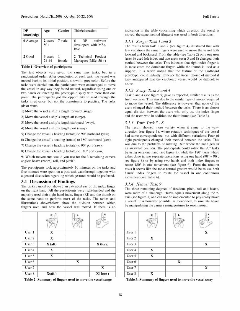
Table 2: Summary of fingers used to move the vessel surge Table 3: Summary of fingers used to move the vessel sway
DP
knowledge
Age Gender Title/education
6 Average
2 users 50+
7 male
6 DP software developers with MSc, BSc
2 Good 6 users 24-44
1 female
2 Technical Product Managers (MSc, 50 +)
Table 1: Overview of participants
The test objects were given the same nine tasks, but in a randomized order. After completion of each task, the vessel was moved back to its initial position, shown in grey color. Before the tasks were carried out, the participants were encouraged to move the vessel in any way they found natural, regardless using one or two hands or touching the prototype display with more than one point. The participants got the opportunity to read through the tasks in advance, but not the opportunity to practice. The tasks given were:
1) Move the vessel a ship’s length forward (surge).
2) Move the vessel a ship’s length aft (surge).
3) Move the vessel a ship’s length starboard (sway).
4) Move the vessel a ship’s length port (sway).
5) Change the vessel’s heading (rotate) to 90° starboard (yaw).
6) Change the vessel’s heading (rotate) to 180° starboard (yaw).
7) Change the vessel’s heading (rotate) to 90° port (yaw).
8) Change the vessel’s heading (rotate) to 180° port (yaw).
9) Which movements would you use for the 3 remaining camera angles: heave (zoom), roll, and pitch?
The participants took approximately 10 minutes on the tasks and five minutes were spent on a post-task walkthrough together with a general discussion regarding which gestures would be preferred.
3.1 Discussion of Findings The tasks carried out showed an extended use of the index finger on the right hand. All the participants were right-handed and the majority used their right hand index finger (RI) and the thumb on the same hand to perform most of the tasks. The tables and illustrations above/below, show the division between which fingers used and how the vessel was moved. If there is no
indication in the table concerning which direction the vessel is moved, the same method (fingers) was used in both directions.
3.1.1 Surge: Task 1 and 2 The results from task 1 and 2 (see figure 4) illustrated that with few variations the same fingers were used to move the vessel both forward and backward. From the table (see Table 2) only one user (user 6) used left index and two users (user 3 and 8) changed their method between the tasks. This indicates that right index finger is in most cases the dominant finger, while the thumb is used as a support. It is worth noting that the texture of the cardboard prototype, could initially influence the users’ choice of method if they anticipated that the cardboard vessel would be difficult to move.
3.1.2 Sway: Task 3 and 4 Task 3 and 4 (see figure 5) gave as expected, similar results as the first two tasks. This was due to the similar type of motion required to move the vessel. The difference is however that none of the users changed their method between the tasks. There is an almost equal division between the users who only use the index finger and the users who in addition use their thumb (see Table 3).
3.1.3 Yaw: Task 5 - 8 The result showed more variety when it came to the yaw- direction (see figure 1), where rotation techniques of the vessel had some correspondence, but with different variations. Four of eight participants changed their method between the tasks. This was due to the problems of rotating 180° where the hand gets in an awkward position. The participants could rotate the 90° tasks by using only one hand (see figure 7), while the 180° tasks where either done in two separate operations using one hand (90° + 90°, see figure 8) or by using two hands and both index fingers to rotate 180° in one movement (see figure 6). From the rotation tasks it seems like the most natural gesture would be to use both hands’ index fingers to rotate the vessel in one continuous movement (see Table 4).
3.1.4 Heave: Task 9 The three remaining degrees of freedom, pitch, roll and heave, were more of a challenge. Heave equals movement along the z-axis (see figure 1) and can not be implemented to physically move a vessel. It is however possible, as mentioned, to simulate heave by manipulating the camera using gestures to zoom in/out.
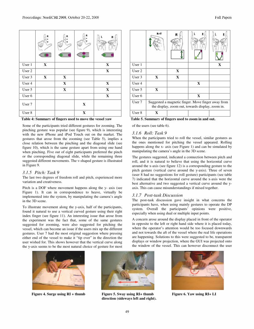
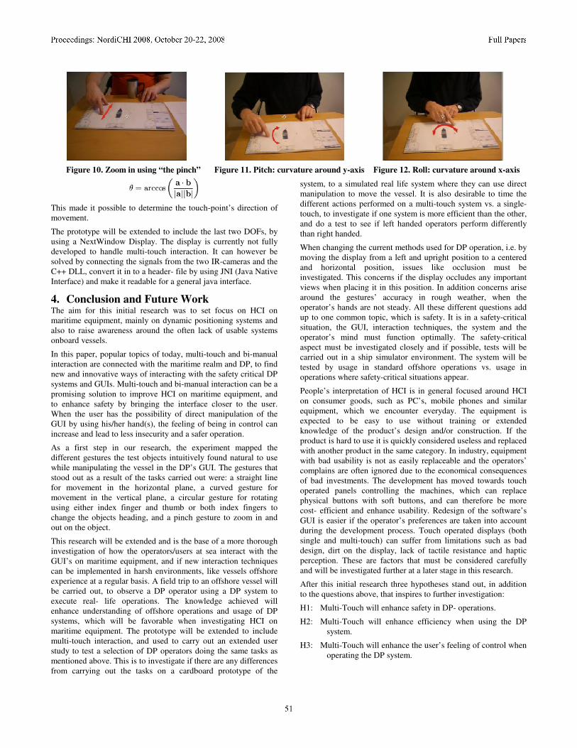
Some of the participants tried different gestures for zooming. The pinching gesture was popular (see figure 9), which is interesting with the new iPhone and iPod Touch out on the market. The gestures that arose from the zooming (see Table 5), implies a close relation between the pinching and the diagonal slide (see figure 10), which is the same gesture apart from using one hand when pinching. Five out of eight participants preferred the pinch or the corresponding diagonal slide, while the remaining three suggested different movements. The v-shaped gesture is illustrated in Figure 9.
3.1.5 Pitch: Task 9 The last two degrees of freedom roll and pitch, experienced more variation and creativeness.
Pitch is a DOF where movement happens along the y- axis (see Figure 1). It can in correspondence to heave, virtually be implemented into the system, by manipulating the camera’s angle in the 3D scene.
To illustrate movement along the y-axis, half of the participants, found it natural to use a vertical curved gesture using their right index finger (see figure 11). An interesting issue that arose from the experiment was the fact that, some of the same gestures suggested for zooming, were also suggested for pitching the vessel, which can become an issue if the users mix up the different gestures. User 7 had the most original suggestion where pressing either end of the vessel to make it “tip over” in the direction the user wished for. This shows however that the vertical curve along the y-axis seems to be the most natural choice of gesture for most
of the users (see table 6).
3.1.6 Roll: Task 9 When the participants tried to roll the vessel, similar gestures as the ones mentioned for pitching the vessel appeared. Rolling happens along the x- axis (see Figure 1) and can be simulated by manipulating the camera’s angle in the 3D scene.
The gestures suggested, indicated a connection between pitch and roll, and it is natural to believe that using the horizontal curve around the x-axis (see figure 12) is a corresponding gesture to the pitch gesture (vertical curve around the y-axis). Three of seven (user 8 had no suggestions for roll gesture) participants (see table 7) indicated that the horizontal curve around the x-axis were the best alternative and two suggested a vertical curve around the y-axis. This can cause misunderstandings if mixed together.
3.1.7 Post-task Discussion The post-task discussion gave insight in what concerns the participants have, when using mainly gestures to operate the DP system. Overall the participants’ opinions were positive, especially when using dual or multiple input points.
A concern arose around the display placed in front of the operator in opposite to the left or right hand side where it is placed today, where the operator’s attention would be too focused downwards and not towards the aft of the vessel where the real life operations are happening. Solutions to this were suggested to be, transparent displays or window projection, where the GUI was projected onto the window of the vessel. This can however disconnect the user
User 1 X X User 1 X
User 2 X User 2 X
User 3 X X User 3 X X
User 4 X X User 4 X
User 5 X X User 5 X
User 6 X User 6 X
User 7 X User 7 Suggested a magnetic finger. Move finger away from
the display, zoom out, towards display, zoom in.
User 8 X User 8 X
Table 4: Summary of fingers used to move the vessel yaw Table 5. Summary of fingers used to zoom in and out.
Figure 4. Surge using RI + thumb Figure 5. Sway using RI+ thumb Figure 6. Yaw using RI+ LI
direction (sideways left and right).

from feeling close to the system and in control. Another important issue was heat that arises from a device on the operator’s lap, response time to get out of the seat in case of an emergency situation onboard and a place to rest the arms while operating the DP system. Further limitations can be the lack of tactile resistance and haptic perception, which will be further investigated as the research proceed.
3.1.8 Conclusion of Experiment After investigating how the eight participants preferred to move the vessel, four typical gestures stood out as a result of the tests.
The right index finger was used for all degrees of freedom, apart from the rotation tasks and zooming where mainly two fingers where used. It is therefore possible to imply that a straight vertical or horizontal gesture is used to move the object in the horizontal plane. A curved gesture seems natural for movement in the vertical plane and a rotating gesture around the center of the object, using thumb + index finger or both index fingers to change the object’s heading. The pinch gesture stood out as the more natural alternative to zooming in and out.
Two of the participants were above 50 years old, but the experiment showed no noticeable difference between the participants above 50 years of age and the remaining six below. The only difference was a clear sign of extended experience within the maritime area for the 50 + participants.
There are also other suggestions and solutions to illustrate the movements, but in this case, these are the ones that seem to feel natural to the participants. An issue for further investigation is to
test how the participants remember the gestures and if they mix the different gestures together.
This experiment will be repeated onboard a vessel in realistic conditions different from the comfort of a lab, to investigate if the participants’ behaviors change from being on shore to being on a ship. This is to get more relevant input from the real users of the system and also to increase the statistical weight of the experiment.
3.1.9 Prototype A prototype implementing gestures using single touch was created and added to the DP system. This made it possible to manipulate the vessel in four of six available degrees of freedom, surge, sway, pitch and roll. The DOFs that needed more than one point/finger touching the screen, such as zoom/heave (see figure 8, 9) and rotate/yaw (see figure 6-8) could not be implemented due to lack of a proper multi-touch display.
By using Java and jME (Java MonkeyEngine, a 3D gaming engine) and a standard touch-display, the touch-point could be tracked and the coordinates inserted into a datastructure. This introduced vectors which were processed and used to calculate the curvature (K). It was now possible to determine what type of
gesture the user was executing (curve or straight line).
In parallel with the calculation of curvature, the angle (Ө) between the vectors’ axes and the speed vector was calculated.
Figure 7. Yaw using RI + thumb Figure 8. Yaw using RI + thumb Figure 9. Zoom in diagonally v-shaped
User 1 X User 1 X
User 2 X User 2 X ( LI)
User 3 X User 3 X X
User 4 X User 4 X
User 5 X User 5 X
User 6 X(RI+
thumb)
User 6 X ( RI
+
thumb)
User 7 X User 7 X
User 8 X User 8 No suggestions
Table 6. Summary of fingers used to pitch the vessel. Table 7. Summary of fingers used to roll the vessel.
This made it possible to determine the touch-point’s direction of movement.
The prototype will be extended to include the last two DOFs, by using a NextWindow Display. The display is currently not fully developed to handle multi-touch interaction. It can however be solved by connecting the signals from the two IR-cameras and the C++ DLL, convert it in to a header- file by using JNI (Java Native Interface) and make it readable for a general java interface.
4. Conclusion and Future Work The aim for this initial research was to set focus on HCI on maritime equipment, mainly on dynamic positioning systems and also to raise awareness around the often lack of usable systems onboard vessels.
In this paper, popular topics of today, multi-touch and bi-manual interaction are connected with the maritime realm and DP, to find new and innovative ways of interacting with the safety critical DP systems and GUIs. Multi-touch and bi-manual interaction can be a promising solution to improve HCI on maritime equipment, and to enhance safety by bringing the interface closer to the user. When the user has the possibility of direct manipulation of the GUI by using his/her hand(s), the feeling of being in control can increase and lead to less insecurity and a safer operation.
As a first step in our research, the experiment mapped the different gestures the test objects intuitively found natural to use while manipulating the vessel in the DP’s GUI. The gestures that stood out as a result of the tasks carried out were: a straight line for movement in the horizontal plane, a curved gesture for movement in the vertical plane, a circular gesture for rotating using either index finger and thumb or both index fingers to change the objects heading, and a pinch gesture to zoom in and out on the object.
This research will be extended and is the base of a more thorough investigation of how the operators/users at sea interact with the GUI’s on maritime equipment, and if new interaction techniques can be implemented in harsh environments, like vessels offshore experience at a regular basis. A field trip to an offshore vessel will be carried out, to observe a DP operator using a DP system to execute real- life operations. The knowledge achieved will enhance understanding of offshore operations and usage of DP systems, which will be favorable when investigating HCI on maritime equipment. The prototype will be extended to include multi-touch interaction, and used to carry out an extended user study to test a selection of DP operators doing the same tasks as mentioned above. This is to investigate if there are any differences from carrying out the tasks on a cardboard prototype of the
system, to a simulated real life system where they can use direct manipulation to move the vessel. It is also desirable to time the different actions performed on a multi-touch system vs. a single- touch, to investigate if one system is more efficient than the other, and do a test to see if left handed operators perform differently than right handed.
When changing the current methods used for DP operation, i.e. by moving the display from a left and upright position to a centered and horizontal position, issues like occlusion must be investigated. This concerns if the display occludes any important views when placing it in this position. In addition concerns arise around the gestures’ accuracy in rough weather, when the operator’s hands are not steady. All these different questions add up to one common topic, which is safety. It is in a safety-critical situation, the GUI, interaction techniques, the system and the operator’s mind must function optimally. The safety-critical aspect must be investigated closely and if possible, tests will be carried out in a ship simulator environment. The system will be tested by usage in standard offshore operations vs. usage in operations where safety-critical situations appear.
People’s interpretation of HCI is in general focused around HCI on consumer goods, such as PC’s, mobile phones and similar equipment, which we encounter everyday. The equipment is expected to be easy to use without training or extended knowledge of the product’s design and/or construction. If the product is hard to use it is quickly considered useless and replaced with another product in the same category. In industry, equipment with bad usability is not as easily replaceable and the operators’ complains are often ignored due to the economical consequences of bad investments. The development has moved towards touch operated panels controlling the machines, which can replace physical buttons with soft buttons, and can therefore be more cost- efficient and enhance usability. Redesign of the software’s GUI is easier if the operator’s preferences are taken into account during the development process. Touch operated displays (both single and multi-touch) can suffer from limitations such as bad design, dirt on the display, lack of tactile resistance and haptic perception. These are factors that must be considered carefully and will be investigated further at a later stage in this research.
After this initial research three hypotheses stand out, in addition to the questions above, that inspires to further investigation:
H1: Multi-Touch will enhance safety in DP- operations.
H2: Multi-Touch will enhance efficiency when using the DP system.
H3: Multi-Touch will enhance the user’s feeling of control when operating the DP system.
Figure 10. Zoom in using “the pinch” Figure 11. Pitch: curvature around y-axis Figure 12. Roll: curvature around x-axis
5. REFERENCES [1] Balakrishnan, R. and Hinckley, K. 1999. The Role of
Kinesthetic Reference Frames in Two-Handed Input Performance. UIST’99. 171 – 178.
[2] Ball, R. et al. 2007. Move to Improve: Promoting Physical Navigation to Increase User Performance with Large Displays. ACM CHI’07 Proceedings. 191 - 200
[3] Benko, H. et al. 2006. Precise Selection Techniques for Multi-Touch Screens. ACM CHI’06 Procs. 1263-1272.
[4] Bray, D. 2003. Dynamic Positioning, 2nd Edition.
[5] Buxton, Bill. 2007. Multi- Touch Systems that I Have Known and Loved. http://www.billbuxton.com/multitouchOverview.html
[6] Buxton, W. and Myers, B. 1986. A Study in Two-Handed Input. ACM CHI Conference on Human Factors in Computing Systems. 321- 326.
[7] Chatty, S. 1994. Extending a Graphical Toolkit for Two-Handed Interaction. ACM UIST’94. 195 -204.
[8] Dix, A., Finlay, J., Abowd, G. and Beale, R. 1997. Human Computer Interaction. 2nd edition. Pearson Education Limited. Prentice Hall International (UK).
[9] Epps. J. et al. 2006. A Study in Hand Shape Use in Tabletop Gesture Interaction. ACM CHI’06 748- 753.
[10] Faulkner, X. 2000. Usability Engineering, Basingstroke: Macmillan Press Ltd.
[11] Forlines, C. et al. 2007. Direct- Touch vs. Mouse Input for Tabletop Displays. ACM CHI 2007 Procs. 647-656.
[12] Gingold, Y. et al. 2006. A Direct Texture Placement and Editing Interface. ACM UIST’06. 23 - 31
[13] Han, Jefferson Y. 2005. Low-Cost Multi-Touch Sensing through Frustrated Total Internal Reflection. UIST’05, October 23-27, 2005, Seattle, Washington USA.
[14] Hancock, M. et al. 2007. Shallow Depth 3D Interaction: Design and Evaluation of One- Two- and Three- Touch Techniques. ACM CHI 2007 Proceedings. 1147 – 1156.
[15] Hancock, M., Carpendale, S., Cockburn, A., 2007. Shallow- Depth 3D Interaction: Design and Evaluation of One-, Two- and Three-Touch Techniques. CHI 2007 Proceedings, Novel Navigation, 1147 – 1156.
[16] Kabbash, P., Buxton, W., Sellen, A. 1994. Two- Handed Input in a Compund Task. CHI’94. ACM Human Factors in Computing Systems. 417 – 423.
[17] Latulipe, C. et al. 2006. symSpline: Symmetric Two-Handed Spline Manipulation. ACM CHI’06 Proceedings. 349 – 358.
[18] Lazet, A. and Schuffel, H. 1977. Some applications of human engineering to wheelhouse design. This Journal, 30(7), 77 -86.
[19] Lee, SK. et al. 1985. A Multi-Touch Three Dimensional Touch- Sensitive Tablet. CHI’85 Proceedings. 21 – 25.
[20] Malik, S. and Laszlo, J. 2004. Visual TouchPad: A Two-Handed Gestural Input Device. ACM ICMI’ 04. 289 – 296.
[21] Mills, S. 1995. To Live or Drown: When Information Systems become Critical. The Computer Journal, Vol. 38. No. 6, 413 – 417.
[22] Mills, S. 1995.Usability Problems of Acoustical Fishing Displays. Displays. 16 (3). 115 – 121.
[23] Mills, S. 2005. Designing Usable Marine Interfaces: Some Issues and Constraints. The Journal of Navigation.58. 67 – 75.2005
[24] Mills, S. 2006.Integrated Marine Electronic Systems – Some User Associated Issues for the Designer. The Journal of Navigation, 59, 423 – 433.
[25] Mills,S. 1998. Integrating information – a task- oriented approach. Interacting with computers 9. 225 - 240.
[26] Mills,S. 2000. Safer Positioning of Electronic Fishing Aids. Cambridge University Press.Journal of Navigation, 53: 355-370.
[27] Murphy, N. 2004. Graphical Interfaces for small places. IEEE Information Professional, April/May, 32-35.
[28] Nishino, H. et al. 1997. Interactive Two- Handed Gesture Interface in 3D Virtual Environments. ACM VRST’97, 1 – 8.
[29] Norman, Donald A. 2002.The Design of Everyday Things. Basic Books.
[30] Owen, R. et al. 2005. When It Gets More Difficult, Use Both Hands-Exploring Bimanual Curve Manipulation. Canadian Human-Computer Communications Society. ACM International Conference Proceeding Series; Vol. 112.Proceedings of Graphics Interface 2005. 17 - 24
[31] Redmill, F. and Rajan, J. 1997. Human Factors in Safety Critical Systems. Oxford: Butterworth Heinemann.
[32] Reikimoto, J. 2002. SmartSkin: An Infrastructure for Freehand Manipulation on Interactive Surfaces. CHI’02. CHI letters, Volume No. 4, Issue No. 1, 113 – 120.
[33] Rubine, D. 1991. Specifying Gestures by Example. Computer Graphics, 25(4), July 1991, 329 – 337.
[34] Wu, M. and Balakrishnan, R. 2003. Multi-Finger and Whole Hand Gestural Interaction Techniques for Multi-User Tabletop Displays. UIST’03. CHI letters, Volume 5, Issue 2, 193 – 202.
[35] Yee, Ka-Ping. 2004. Two- Handed Interaction on a Tablet Display. ACM CHI’04. 1493 - 1496
[36] Zeleznik, R.C.et al. 1997. Two Pointer Input for 3D Interaction. ACM Symposium on Interactive 3D Graphics. 115 – 120.
[37] Galliers, J. et al. 1999. An impact analysis method for safety-critical user interface design. ACM Transactions on Human Computer Interaction (TOCHI), Volume 6, Issue 4. 341 – 369.
[38] MacKay, W.E. 1999. Is Paper Safer? The Role of Paper Flight Strips in Air Traffic Control. ACM TOCHI, 6(4). 311 – 340.