Discussion on Fabrication and Lifting of Floatation Tanks ...
5
Discussion on Fabrication and Lifting of Floatation Tanks of Jacket Sun Ning 1, a Liu Chao 1, b Li Chengbao 1, c Zhuang Hongchang 1, d Chao Yili 1, e Shen Yuji 1, f Wei Qiang 1,g Wang Zengbo 1,h 1 No.492, Lianjiang Road, Qingdao E&T Development Zone, China a [email protected], b [email protected], c [email protected], d [email protected], e [email protected], f [email protected], g [email protected], h [email protected] Keywords: Floatation tanks, Gravity jacket, Fabrication, Lifting, Abstract. Floatation tanks are usually designed in gravity jacket, which can provide enough floatation and make sure the accurate location of jackets during offshore installation of gravity jacket. Floatation tanks have the following characteristic: major diameter, thin thickness and there are large of internal stiffeners inside of floatation tanks to make sure structural strength of floatation tanks. It causes much difficulty to site fabrication and installation because of above characteristic. This paper briefly describes how to fabricate and install of floatation tanks, which will be helpful to fabricate and assembly this type of structures. Introduction Floatation tanks will be designed on the top of gravity jacket, which provide enough floatation during offshore installation of gravity jacket [1].The floatation tanks mentioned in this paper will be fabricated and installed to 27000T weight jacket. The quantity of floatation tanks is 2 and located at the two side of jacket. The detail information of floatation tanks shows in the Table 1. Figure 1 shows the 3D model of jacket and floatation tanks [2]. Table 1 Detail information of Floatation Tanks Name No . Dimension(m) Diameter(mm) Thickness(mm) Single Weight(t) Total Weight(t) Floatation tanks 2 44.8x47.368 7386/6500/6000 30/25/15 1334.8 2669.6 Fabrication of floatation tanks The weight of floatation tanks is 1334.8T which is over the lifting capacity of lifting equipment and facility. So floatation tanks will be separated to two parts named Top segment and Bottom segment for convenience to fabricate and lift tanks. Figure 2 shows the field welding location of floatation tank. Because the structure of two floadtaion tank is same, this paper is only descipe one tank. Fig.1 3D model of Jacket and floatation tanks Fig.2 Filed welding location International Conference on Civil, Transportation and Environment (ICCTE 2016) © 2016. The authors - Published by Atlantis Press 143
Transcript of Discussion on Fabrication and Lifting of Floatation Tanks ...
Discussion on Fabrication and Lifting of Floatation Tanks of Jacket
Sun Ning1, a Liu Chao1, b Li Chengbao1, c Zhuang Hongchang1, d Chao Yili1, e Shen Yuji1, f Wei Qiang1,g Wang Zengbo1,h
1 No.492, Lianjiang Road, Qingdao E&T Development Zone, China a [email protected], b [email protected], c [email protected],
d [email protected], e [email protected], f [email protected],
g [email protected], h [email protected]
Keywords: Floatation tanks, Gravity jacket, Fabrication, Lifting, Abstract. Floatation tanks are usually designed in gravity jacket, which can provide enough floatation and make sure the accurate location of jackets during offshore installation of gravity jacket. Floatation tanks have the following characteristic: major diameter, thin thickness and there are large of internal stiffeners inside of floatation tanks to make sure structural strength of floatation tanks. It causes much difficulty to site fabrication and installation because of above characteristic. This paper briefly describes how to fabricate and install of floatation tanks, which will be helpful to fabricate and assembly this type of structures.
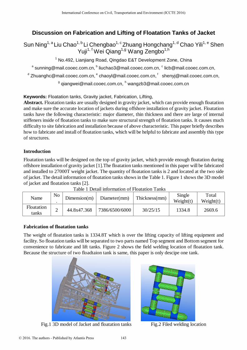
Introduction Floatation tanks will be designed on the top of gravity jacket, which provide enough floatation during offshore installation of gravity jacket [1].The floatation tanks mentioned in this paper will be fabricated and installed to 27000T weight jacket. The quantity of floatation tanks is 2 and located at the two side of jacket. The detail information of floatation tanks shows in the Table 1. Figure 1 shows the 3D model of jacket and floatation tanks [2].
Table 1 Detail information of Floatation Tanks
Name No. Dimension(m) Diameter(mm) Thickness(mm) Single
Weight(t) Total
Weight(t) Floatation
tanks 2 44.8x47.368 7386/6500/6000 30/25/15 1334.8 2669.6
Fabrication of floatation tanks The weight of floatation tanks is 1334.8T which is over the lifting capacity of lifting equipment and facility. So floatation tanks will be separated to two parts named Top segment and Bottom segment for convenience to fabricate and lift tanks. Figure 2 shows the field welding location of floatation tank. Because the structure of two floadtaion tank is same, this paper is only descipe one tank.
Fig.1 3D model of Jacket and floatation tanks Fig.2 Filed welding location
International Conference on Civil, Transportation and Environment (ICCTE 2016)
© 2016. The authors - Published by Atlantis Press 143

Fanrication of tubular with internal stiffeners The diameter of tubulars is 7386mm, 6500mm and 6000mm, which is over the rolling capacity of rolling machine. So this paper considers firstly fabricate half-circle tubular and then weld the two half-circle tubular. The following steps show the detail fabrication sequence of tubular: Step 1 layout of temporary supports and limited strucutre. Step 2 lifting and fastening the rolled half-circle tubular to welding locaion. Step 3 lifting another half-circle tubular to the welding location and make sure the gap between two half-circle tubular is 30mm for installation of internal stiffeners. Step 4 fabrication of internal stiffeners Step 5 installation of internal stiffeners to inside of tubular Step 6 adjustment of location of internal stiffeners to meet the dimension requirement. Step 7 Welding the two half-circle tubular, tubular and stiffeners after dimension check then installation of temporary supports for avoiding distortion. Step 8 splice two fanricated tubulars following the above 7 steps. Step 9 splice spliced tubulars to the max. length 12m Step 10 rotation of spliced tubular to horizontal and splice to length required on drawings. Step 11 cut the end of tubular according to requirement of drawings
Fig.3 Fabrication sequence of tubular
Fabrication of Top and Bottom segments After fabrication of tubular, Top and Bottom segments shall be fabricated. Figure 4 shows the general sequence. After fitting up dimension check shall be carried to meet the requirement of dimension.
144
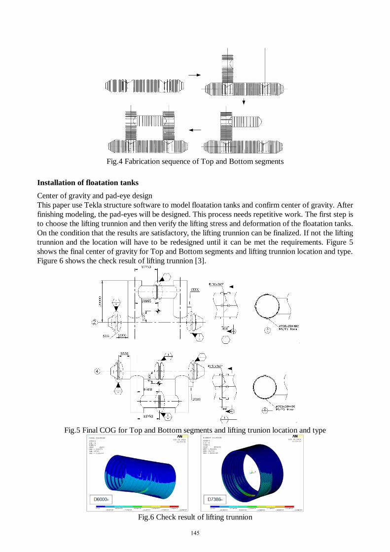
Fig.4 Fabrication sequence of Top and Bottom segments
Installation of floatation tanks Center of gravity and pad-eye design This paper use Tekla structure software to model floatation tanks and confirm center of gravity. After finishing modeling, the pad-eyes will be designed. This process needs repetitive work. The first step is to choose the lifting trunnion and then verify the lifting stress and deformation of the floatation tanks. On the condition that the results are satisfactory, the lifting trunnion can be finalized. If not the lifting trunnion and the location will have to be redesigned until it can be met the requirements. Figure 5 shows the final center of gravity for Top and Bottom segments and lifting trunnion location and type. Figure 6 shows the check result of lifting trunnion [3].
Fig.5 Final COG for Top and Bottom segments and lifting trunion location and type
Fig.6 Check result of lifting trunnion
145
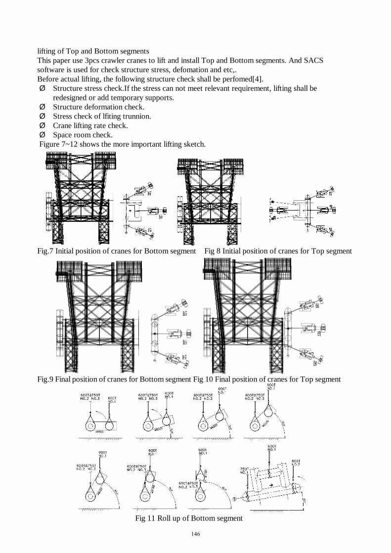
lifting of Top and Bottom segments This paper use 3pcs crawler cranes to lift and install Top and Bottom segments. And SACS software is used for check structure stress, defomation and etc,. Before actual lifting, the following structure check shall be perfomed[4]. Ø Structure stress check.If the stress can not meet relevant requirement, lifting shall be
redesigned or add temporary supports. Ø Structure deformation check. Ø Stress check of lfiting trunnion. Ø Crane lifting rate check. Ø Space room check. Figure 7~12 shows the more important lifting sketch.
Fig.7 Initial position of cranes for Bottom segment Fig 8 Initial position of cranes for Top segment
Fig.9 Final position of cranes for Bottom segment Fig 10 Final position of cranes for Top segment
Fig 11 Roll up of Bottom segment
146
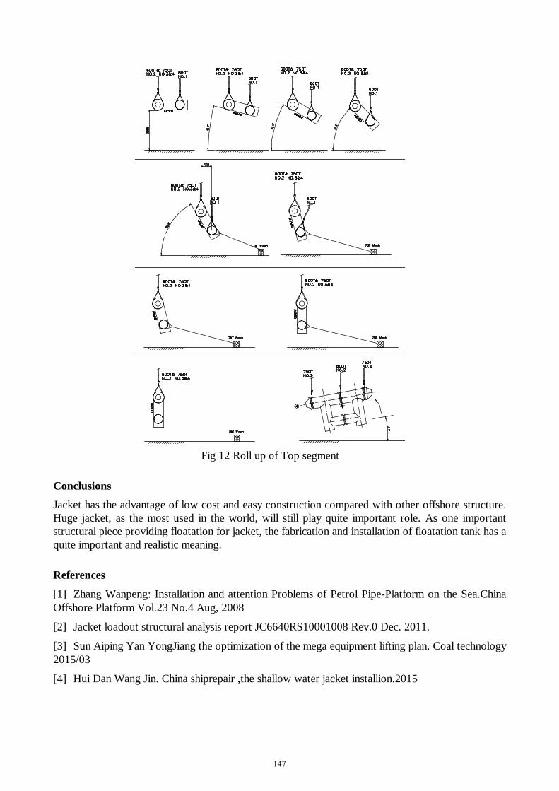
Fig 12 Roll up of Top segment
Conclusions Jacket has the advantage of low cost and easy construction compared with other offshore structure. Huge jacket, as the most used in the world, will still play quite important role. As one important structural piece providing floatation for jacket, the fabrication and installation of floatation tank has a quite important and realistic meaning.
References
[1] Zhang Wanpeng: Installation and attention Problems of Petrol Pipe-Platform on the Sea.China Offshore Platform Vol.23 No.4 Aug, 2008
[2] Jacket loadout structural analysis report JC6640RS10001008 Rev.0 Dec. 2011.
[3] Sun Aiping Yan YongJiang the optimization of the mega equipment lifting plan. Coal technology 2015/03
[4] Hui Dan Wang Jin. China shiprepair ,the shallow water jacket installion.2015
147


![Dossier d'info - Trophées des think tanks 120912 VF[1]...!!!!! !!en!partenariatavec!! 4! Les Trophées des think tanks français 2012 !! Lepalmarès!2012!! En!2012,!4!trophées!ontété!décernés!:!](https://static.fdocuments.fr/doc/165x107/5f24d04a5028573a192773db/dossier-dinfo-trophes-des-think-tanks-120912-vf1-enpartenariatavec.jpg)