CP150-CP200 User Guide -...
44
CP150 ™ /CP200 ™ Commercial Series Two-Way Radio User Guide Manuel de l'utilisateur de la radio bidirectionnelle
Transcript of CP150-CP200 User Guide -...

MOTOROLA, the Stylized M Logo, and Radius are registered in the US Patent & Trademark Office.All other product or service names are the property of their respective owners. © Motorola, Inc. 2002, 2003. All rights reserved. Printed in U.S.A.
MOTOROLA, le logotype au M stylisé et Radius sont enregistrés auprès du Bureau des marques et brevets des États-Unis.Tous les autres noms de produits et de services sont la propriété de leurs titulaires respectifs.© Motorola, Inc. 2002, 2003. Tous droits réservés. Imprimé aux États-Unis.
*6880309N60*6880309N60-A
CP150™/CP200™
Commercial SeriesTwo-Way Radio User Guide
Manuel de l'utilisateurde la radio bidirectionnelle
309N60-A_cvr.qxd 8/19/2003 10:43 AM Page 1

1English
CO
NT
EN
TS
CONTENTS
Computer Software Copyrights . . . . . . . . . . 2
Safety and Warranty . . . . . . . . . . . . . . . . . 3
Improved Audio Features . . . . . . . . . . . . . 16Companding . . . . . . . . . . . . . . . . . . . . 16
Getting Started . . . . . . . . . . . . . . . . . . . . 17
Battery Information . . . . . . . . . . . . . . . . . . 17our Battery . . . . . . . . . . . . . 17. . . . . . . . . . . . . . . . . . . . . . 17ers. . . . . . . . . . . . . . . . . . . 18ger . . . . . . . . . . . . . . . . . . . 18er. . . . . . . . . . . . . . . . . . . . 19rmation . . . . . . . . . . . . . . . 20e Battery . . . . . . . . . . . . . . 20he Battery . . . . . . . . . . . . . 20e Antenna . . . . . . . . . . . . . 21he Antenna . . . . . . . . . . . . 21e Belt Clip . . . . . . . . . . . . . 22he Belt Clip . . . . . . . . . . . . 22dio On or Off . . . . . . . . . . . 23olume . . . . . . . . . . . . . . . . 23dio Channel . . . . . . . . . . . . 23. . . . . . . . . . . . . . . . . . . . . . 24. . . . . . . . . . . . . . . . . . . . . . 24. . . . . . . . . . . . . . . . . . . . . . 24
. . . . . . . . . . . . . . . . . . . . . 25 a VOX Headset . . . . . . . . 25 Disabling VOX . . . . . . . . . 25 Headset Sidetone . . . . . . 25et. . . . . . . . . . . . . . . . . . . . 25eadset with In-Line PTT . . 26
Non-displayTOC.fm Page 1 Monday, November 17, 2003 1:55 PM
Product Safety and RF Exposure Compliance . . . . . . . . . . . . . . . . . . . . . . . . 3
Battery Information . . . . . . . . . . . . . . . . . . . 3Charging Batteries . . . . . . . . . . . . . . . . . 3
Limited Warranty . . . . . . . . . . . . . . . . . . . . . 4
Introduction . . . . . . . . . . . . . . . . . . . . . . . . 9
Conventional Radio Systems . . . . . . . . . . . 9CP150™/CP200™ Radio Features . . . . . . 9
Radio Wide Features . . . . . . . . . . . . . . . 9Signaling Features . . . . . . . . . . . . . . . . . 9
Radio Overview . . . . . . . . . . . . . . . . . . . . 11
Parts of the Radio . . . . . . . . . . . . . . . . . . . 11CP150/CP200 Models . . . . . . . . . . . . . 11On/Off/Volume Knob . . . . . . . . . . . . . . 12Channel Selector Knob . . . . . . . . . . . . 12Push-to-Talk (PTT) Button . . . . . . . . . . 12Microphone . . . . . . . . . . . . . . . . . . . . . 12LED Indicator . . . . . . . . . . . . . . . . . . . . 12Programmable Buttons . . . . . . . . . . . . 13
Indicator Tones . . . . . . . . . . . . . . . . . . . . . 15Audio Indicators for Programmable
Buttons . . . . . . . . . . . . . . . . . . . . . . . . . . 15
Charging YWall Charger. Desktop Charg
Rapid CharSlow Charg
Accessory InfoAttaching thRemoving tAttaching thRemoving tAttaching thRemoving t
Turning the RaAdjusting the VSelecting a RaReceiving . . . Monitoring. . . Transmitting . VOX Operation
ConnectingEnabling or
Enable/DisableVOX HeadsNon-VOX H
En
CO
NT
EN
TS
Repeater or Talkaround Mode . . . . . . . . . 26Setting Tight or Normal Squelch. . . . . . . . 26Setting the Power Level . . . . . . . . . . . . . . 27
Radio Calls . . . . . . . . . . . . . . . . . . . . . . . 29
COMPUTER SOFTWARE COPYRIGHTS
The Motorola products described in this nclude copyrighted Motorola rams stored in semiconductor ther media. Laws in the United er countries preserve for in exclusive rights for
omputer programs including, but the exclusive right to copy or ny form the copyrighted ram. Accordingly, any otorola computer programs
he Motorola products described l may not be copied, reproduced, rse-engineered, or distributed in ithout the express written
Motorola. Furthermore, the otorola products shall not be nt either directly or by toppel, or otherwise, any license yrights, patents or patent f Motorola, except for the normal license to use that arises by w in the sale of a product.
Non-displayTOC.fm Page 2 Monday, November 17, 2003 1:55 PM
2glish
Receiving a Selective Call . . . . . . . . . . . . 29Receiving a Call Alert Page . . . . . . . . . . . 29
Scan . . . . . . . . . . . . . . . . . . . . . . . . . . . . . 31
Talkback . . . . . . . . . . . . . . . . . . . . . . . . . . 31Starting System Scan . . . . . . . . . . . . . . . . 31Stopping System Scan . . . . . . . . . . . . . . . 31Starting Auto Scan . . . . . . . . . . . . . . . . . . 31Stopping Auto Scan . . . . . . . . . . . . . . . . . 31Deleting a Nuisance Channel . . . . . . . . . . 32
Restoring a Channel to the Scan List . 32Prioritizing a Scan List Member . . . . . . . . 33
Accessories . . . . . . . . . . . . . . . . . . . . . . 35
Carry Accessories. . . . . . . . . . . . . . . . . . . 35Chargers . . . . . . . . . . . . . . . . . . . . . . . . . . 35Batteries . . . . . . . . . . . . . . . . . . . . . . . . . . 35Headsets . . . . . . . . . . . . . . . . . . . . . . . . . 36Surveillance Accessories . . . . . . . . . . . . . 36Remote Speaker Microphones . . . . . . . . . 37Ear Microphone Systems . . . . . . . . . . . . . 37Antennas . . . . . . . . . . . . . . . . . . . . . . . . . 38Miscellaneous. . . . . . . . . . . . . . . . . . . . . . 38
manual may icomputer progmemories or oStates and othMotorola certacopyrighted cnot limited to,reproduce in acomputer progcopyrighted Mcontained in tin this manuamodified, reveany manner wpermission ofpurchase of Mdeemed to graimplication, esunder the copapplications onon-exclusiveoperation of la
3English
SA
FE
TY
AN
D
WA
RR
AN
TY
SAFETY AND WARRANTY
PRODUCT SAFETY AND RF EXPOSURE COMPLIANCE
BATTERY INFORMATIONCharging Batteries
This product is powered by a nickel-cadmium (NICd) or lithium-ion (Lilon) rechargeable
the battery before use to capacity and performance. designed specifically to be orola charger. Charging in non-ent may lead to battery
d the battery warranty.
rging a battery attached to a the radio off to ensure a full
uld be at about 77°F (25°C) re), whenever possible.
battery (below 50° F [10°C]) kage of electrolyte and re of the battery. Charging a
ve 95°F [35°C]) results in ge capacity, affecting the the radio. Motorola rapid-rate contain a temperature-
o ensure that batteries are he temperature limits stated
00_SafetyNA.fm Page 3 Monday, November 17, 2003 1:55 PM
ATTENTION!
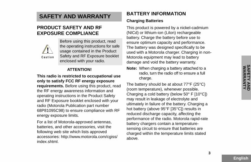
This radio is restricted to occupational use only to satisfy FCC RF energy exposure requirements. Before using this product, read the RF energy awareness information and operating instructions in the Product Safety and RF Exposure booklet enclosed with your radio (Motorola Publication part number 68P81095C98) to ensure compliance with RF energy exposure limits.
For a list of Motorola-approved antennas, batteries, and other accessories, visit the following web site which lists approved accessories: http://www.motorola.com/cgiss/index.shtml.
battery. Charge ensure optimumThe battery wasused with a MotMotorola equipmdamage and voi
Note: When charadio, turncharge.
The battery sho(room temperatuCharging a coldmay result in leaultimately in failuhot battery (aboreduced discharperformance of battery chargerssensing circuit tcharged within tabove.
Before using this product, read the operating instructions for safe usage contained in the Product Safety and RF Exposure booklet enclosed with your radio.
!C a u t i o n

En
SA
FE
TY
AN
D
WA
RR
AN
TY
LIMITED WARRANTY
MOTOROLA COMMUNICATION PRODUCTS
This express limited warranty is extended by MOTOROLA to the original end user purchaser only and is not assignable or transferable to any other party. This is the complete warranty for the Product manufactured by MOTOROLA.
LA assumes no obligations or liability ns or modifications to this warranty de in writing and signed by an officer OLA. Unless made in a separate t between MOTOROLA and the d user purchaser, MOTOROLA does t the installation, maintenance or the Product.
LA cannot be responsible in any way cillary equipment not furnished by LA which is attached to or used in with the Product, or for operation of t with any ancillary equipment, and all ment is expressly excluded from this ecause each system which may use
ct is unique, MOTOROLA disclaims range, coverage, or operation of the a whole under this warranty.
00_SafetyNA.fm Page 4 Monday, November 17, 2003 1:55 PM
4glish
I. WHAT THIS WARRANTY COVERS AND FOR HOW LONG:
MOTOROLA INC. (“MOTOROLA”) warrants the MOTOROLA manufactured Communication Products listed below (“Product”) against defects in material and workmanship under normal use and service for a period of time from the date of purchase as scheduled below:
CP150/CP200 Portable Units Two (2) YearsProduct Accessories One (1) Year
Motorola, at its option, will at no charge either repair the Product (with new or reconditioned parts), replace it (with a new or reconditioned Product), or refund the purchase price of the Product during the warranty period provided it is returned in accordance with the terms of this warranty. Replaced parts or boards are warranted for the balance of the original applicable warranty period. All replaced parts of Product shall become the property of MOTOROLA.
MOTOROfor additiounless maof MOTORagreemenoriginal ennot warranservice of
MOTOROfor any anMOTOROconnectionthe Producsuch equipwarranty. Bthe Produliability forsystem as
5English
SA
FE
TY
AN
D
WA
RR
AN
TY
II. GENERAL PROVISIONS:
This warranty sets forth the full extent of MOTOROLA's responsibilities regarding the Product. Repair, replacement or refund of the purchase price, at MOTOROLA’s option, is the
III. STATE LAW RIGHTS:
SOME STATES DO NOT ALLOW THE EXCLUSION OR LIMITATION OF INCIDENTAL OR CONSEQUENTIAL DAMAGES OR LIMITATION ON HOW LONG AN IMPLIED
ASTS, SO THE ABOVE R EXCLUSIONS MAY NOT
ives specific legal rights, and ther rights which may vary from
T WARRANTY SERVICE:
e proof of purchase (bearing the e and Product item serial number) ive warranty service and, also, the Product item, transportation repaid, to an authorized warranty . Warranty service will be torola through one of its anty service locations. If you first pany which sold you the Product
communication service provider), our obtaining warranty service. ll Motorola at 1-800-927-2744
00_SafetyNA.fm Page 5 Monday, November 17, 2003 1:55 PM
exclusive remedy. THIS WARRANTY IS GIVEN IN LIEU OF ALL OTHER EXPRESS WARRANTIES. IMPLIED WARRANTIES, INCLUDING WITHOUT LIMITATION, IMPLIED WARRANTIES OF MERCHANTABILITY AND FITNESS FOR A PARTICULAR PURPOSE, ARE LIMITED TO THE DURATION OF THIS LIMITED WARRANTY. IN NO EVENT SHALL MOTOROLA BE LIABLE FOR DAMAGES IN EXCESS OF THE PURCHASE PRICE OF THE PRODUCT, FOR ANY LOSS OF USE, LOSS OF TIME, INCONVENIENCE, COMMERCIAL LOSS, LOST PROFITS OR SAVINGS OR OTHER INCIDENTAL, SPECIAL OR CONSEQUENTIAL DAMAGES ARISING OUT OF THE USE OR INABILITY TO USE SUCH PRODUCT, TO THE FULL EXTENT SUCH MAY BE DISCLAIMED BY LAW.
WARRANTY LLIMITATION OAPPLY.
This warranty gthere may be ostate to state.
IV. HOW TO GE
You must providdate of purchasin order to recedeliver or send and insurance pservice locationprovided by Moauthorized warrcontact the com(e.g., dealer or it can facilitate yYou can also caUS/Canada.
En
SA
FE
TY
AN
D
WA
RR
AN
TY
V. WHAT THIS WARRANTY DOES NOT COVER:A Defects or damage resulting from use of the
Product in other than its normal and
H A Product which, due to illegal or unauthorized alteration of the software/firmware in the Product, does not function in accordance with MOTOROLA’s published specifications or the FCC type acceptance
g in effect for the Product at the time oduct was initially distributed from ROLA.
hes or other cosmetic damage to ct surfaces that does not affect the ion of the Product.
l and customary wear and tear.
AND SOFTWARE PROVISIONS:
A will defend, at its own expense, any t against the end user purchaser to
that it is based on a claim that the parts infringe a United States patent, ROLA will pay those costs and inally awarded against the end user in any such suit which are attributable h claim, but such defense and are conditioned on the following:
OTOROLA will be notified promptly in by such purchaser of any notice of laim;
00_SafetyNA.fm Page 6 Monday, November 17, 2003 1:55 PM
6glish
customary manner.
B Defects or damage from misuse, accident, water, or neglect.
C Defects or damage from improper testing, operation, maintenance, installation, alteration, modification, or adjustment.
D Breakage or damage to antennas unless caused directly by defects in material workmanship.
E A Product subjected to unauthorized Product modifications, disassemblies or repairs (including, without limitation, the addition to the Product of non-Motorola supplied equipment) which adversely affect performance of the Product or interfere with Motorola's normal warranty inspection and testing of the Product to verify any warranty claim.
F Product which has had the serial number removed or made illegible.
G Freight costs to the repair depot.
labelinthe PrMOTO
I ScratcProduoperat
J Norma
VI. PATENT
MOTOROLsuit broughthe extent Product orand MOTOdamages fpurchaserto any sucpayments
A that Mwritingsuch c

7English
SA
FE
TY
AN
D
WA
RR
AN
TY
B that MOTOROLA will have sole control of the defense of such suit and all negotiations for its settlement or compromise; and
C should the Product or parts become, or in MOTOROLA’s opinion be likely to become,
respect to infringement of patents by the Product or any parts thereof.
Laws in the United States and other countries preserve for MOTOROLA certain exclusive rights for copyrighted MOTOROLA software such as
e rights to reproduce in copies and opies of such Motorola software. A software may be used in only the which the software was originally nd such software in such Product
replaced, copied, distributed, any way, or used to produce any hereof. No other use including, tation, alteration, modification, n, distribution, or reverse engineering TOROLA software or exercise of
ch MOTOROLA software is permitted. is granted by implication, estoppel or nder MOTOROLA patent rights or
NING LAW:ty is governed by the laws of the ois, USA.
00_SafetyNA.fm Page 7 Monday, November 17, 2003 1:55 PM
the subject of a claim of infringement of a United States patent, that such purchaser will permit MOTOROLA, at its option and expense, either to procure for such purchaser the right to continue using the Product or parts or to replace or modify the same so that it becomes non-infringing or to grant such purchaser a credit for the Product or parts as depreciated and accept its return. The depreciation will be an equal amount per year over the lifetime of the Product or parts as established by MOTOROLA.
MOTOROLA will have no liability with respect to any claim of patent infringement which is based upon the combination of the Product or parts furnished hereunder with software, apparatus or devices not furnished by MOTOROLA, nor will MOTOROLA have any liability for the use of ancillary equipment or software not furnished by MOTOROLA which is attached to or used in connection with the Product. The foregoing states the entire liability of MOTOROLA with
the exclusivdistribute cMOTOROLProduct in embodied amay not bemodified inderivative twithout limireproductioof such MOrights in suNo license otherwise ucopyrights.
VII. GOVERThis WarranState of Illin

En
SA
FE
TY
AN
D
WA
RR
AN
TY
Notes:
00_SafetyNA.fm Page 8 Monday, November 17, 2003 1:55 PM
8glish
9English
INT
RO
DU
CT
ION
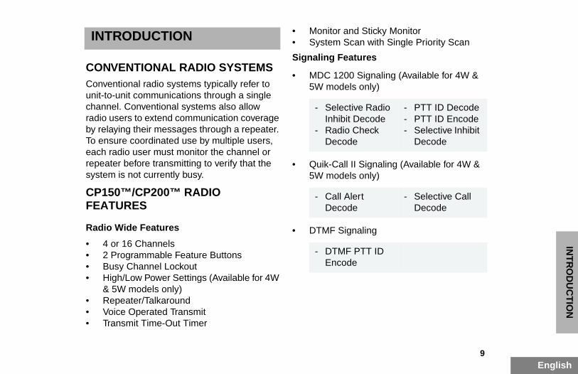
INTRODUCTION
CONVENTIONAL RADIO SYSTEMS
• Monitor and Sticky Monitor• System Scan with Single Priority Scan
Signaling Features
• MDC 1200 Signaling (Available for 4W & dels only)
all II Signaling (Available for 4W & dels only)
ignaling
ective Radio bit Decodeio Check ode
- PTT ID Decode- PTT ID Encode- Selective Inhibit
Decode
l Alert ode
- Selective Call Decode
F PTT ID ode
01_Introduction.fm Page 9 Monday, November 17, 2003 3:49 PM
Conventional radio systems typically refer to unit-to-unit communications through a single channel. Conventional systems also allow radio users to extend communication coverage by relaying their messages through a repeater. To ensure coordinated use by multiple users, each radio user must monitor the channel or repeater before transmitting to verify that the system is not currently busy.
CP150™/CP200™ RADIO FEATURES
Radio Wide Features
• 4 or 16 Channels• 2 Programmable Feature Buttons• Busy Channel Lockout• High/Low Power Settings (Available for 4W
& 5W models only)• Repeater/Talkaround• Voice Operated Transmit• Transmit Time-Out Timer
5W mo
• Quik-C5W mo
• DTMF S
- SelInhi
- RadDec
- CalDec
- DTMEnc

En
INT
RO
DU
CT
ION
Notes:
01_Introduction.fm Page 10 Monday, November 17, 2003 1:56 PM
10glish
11English
RA
DIO
OV
ER
VIE
W
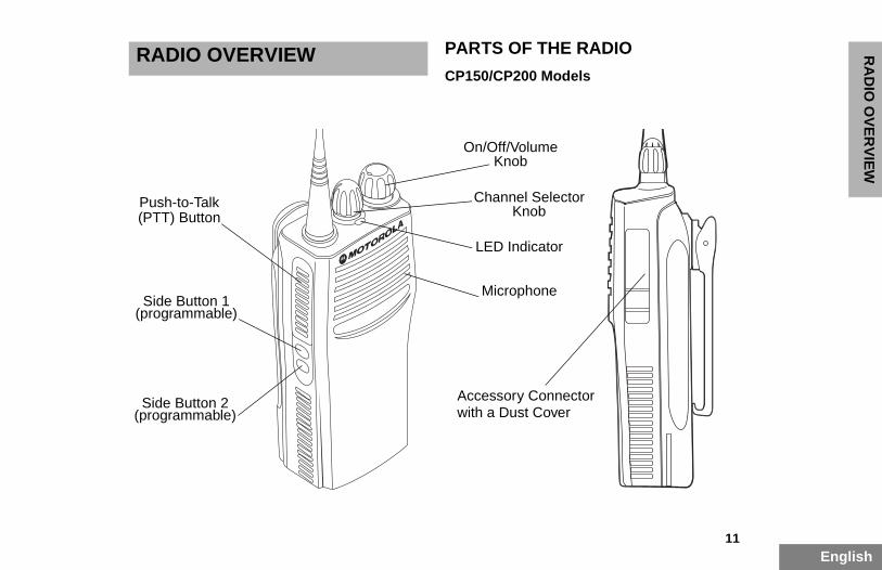
RADIO OVERVIEW PARTS OF THE RADIO
CP150/CP200 Models
Connector Cover
icator
lume
Selectorob
one
02_Overview.fm Page 11 Monday, November 17, 2003 1:56 PM
(programmable)Side Button 1
Push-to-Talk(PTT) Button
(programmable)Side Button 2 Accessory
with a Dust
LED Ind
On/Off/VoKnob
ChannelKn
Microph

En
RA
DIO
OV
ER
VIE
W
On/Off/Volume Knob
Turns the radio on or off, and adjusts the radio’s volume.
Basic Features
LED State/Color Indication
Red Transmitting
Flashing Red Receiving
een Scanning for activity
llow Indicates receiving a Call Alert
all†
llowIndicates receiving a Selective Call
itor/Open Squelch
While monitoring
y
d itting
Low battery level
or 4W and 5W models only.
02_Overview.fm Page 12 Monday, November 17, 2003 1:56 PM
12glish
Channel Selector Knob
Switches the radio to different channels.
Push-to-Talk (PTT) Button
Press and hold down this button to talk (transmit); release it to listen.
Microphone
When sending a message, hold the microphone 1 to 2 inches (2.5 to 5 cm) away from your mouth, and speak clearly into it.
LED Indicator
Indicates power-up, transmit, receive, scan status, Call Alert™, Selective Call, Monitor, and battery status.
Scan
Flashing Gr
Call Alert†
Flashing Ye
Selective C
Flashing Ye
Sticky Mon
Yellow
Low Batter
Flashing Rewhen transm
†Available f

13English
RA
DIO
OV
ER
VIE
W
Battery Charge Status
You can check battery charge status if your dealer has preprogrammed one of the programmable buttons. Hold down the
Some buttons can access up to two features, depending on the type of button press:
• short press — quickly pressing and releas-ing the programmable buttons
s — pressing and holding the able buttons for a period of time 1/2 seconds or programmed ore releasing
n — pressing and holding down mmable buttons while checking aking adjustments
n how your radio has been by your dealer, these functions EITHER through a short press ess, but NOT both.f programmable radio features nding page references appears page 14.e” column, have your dealer write grammable buttons next to the have been programmed to them.
02_Overview.fm Page 13 Monday, November 17, 2003 1:56 PM
preprogrammed Battery Indicator button. The charge status is shown by the color of the radio’s LED indicator.
Programmable Buttons
The two side buttons on your radio can be programmed by your dealer as shortcuts to various radio features.Check with your dealer for a complete list of functions your radio supports.
• long presprogramm(default 1 value) bef
• hold dowthe prograstatus or m
Depending oprogrammedare activatedOR a long prA summary oand correspobeginning onIn the “Featurdown the profeatures that
BatteryLevel
LEDIndicator
Good Green
Sufficient Yellow
Low Flashing Red
Very Low None
En
RA
DIO
OV
ER
VIE
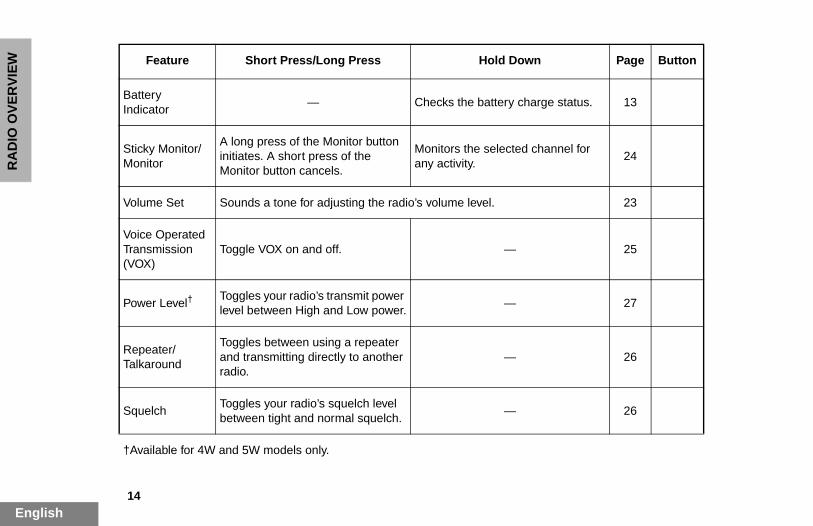
W Feature Short Press/Long Press Hold Down Page Button
Battery— Checks the battery charge status. 13
lected channel for 24
23
— 25
— 27
— 26
— 26
02_Overview.fm Page 14 Monday, November 17, 2003 1:56 PM
14glish
Indicator
Sticky Monitor/Monitor
A long press of the Monitor button initiates. A short press of theMonitor button cancels.
Monitors the seany activity.
Volume Set Sounds a tone for adjusting the radio’s volume level.
Voice Operated Transmission (VOX)
Toggle VOX on and off.
Power Level†Toggles your radio’s transmit power level between High and Low power.
Repeater/Talkaround
Toggles between using a repeater and transmitting directly to another radio.
SquelchToggles your radio’s squelch level between tight and normal squelch.
†Available for 4W and 5W models only.
15English
RA
DIO
OV
ER
VIE
W
ATORS FOR ABLE BUTTONS
able buttons use tones to two modes:
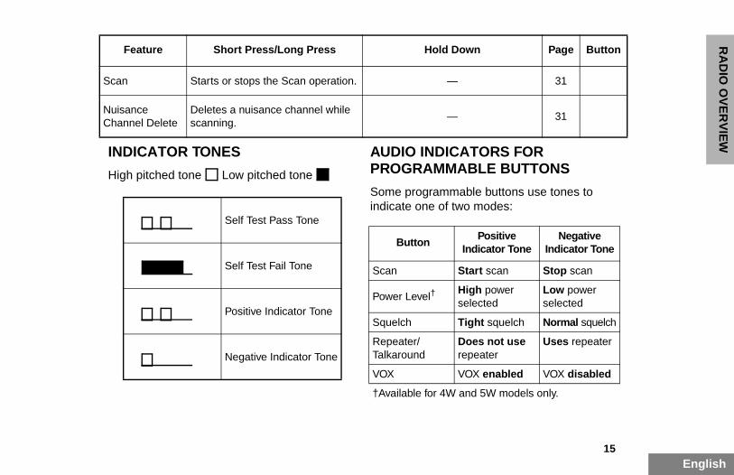
Scan Starts or stops the Scan operation. — 31
31
Feature Short Press/Long Press Hold Down Page Button
Positive Indicator Tone
Negative Indicator Tone
Start scan Stop scan
High power selected
Low power selected
Tight squelch Normal squelch
Does not use repeater
Uses repeater
VOX enabled VOX disabled
and 5W models only.
02_Overview.fm Page 15 Monday, November 17, 2003 1:56 PM
INDICATOR TONES
High pitched tone Low pitched tone
AUDIO INDICPROGRAMM
Some programmindicate one of
Nuisance Channel Delete
Deletes a nuisance channel while scanning.
—
Self Test Pass Tone
Self Test Fail Tone
Positive Indicator Tone
Negative Indicator Tone
Button
Scan
Power Level†
Squelch
Repeater/Talkaround
VOX
†Available for 4W
En
RA
DIO
OV
ER
VIE
W
IMPROVED AUDIO FEATURES
Companding
Companding is a feature that allows further
02_Overview.fm Page 16 Monday, November 17, 2003 1:56 PM
16glish
improvement of voice quality. It compresses your voice at transmission, and expands it when receiving while simultaneously reducing extraneous noise. However, to enjoy this benefit, all transmitting and receiving radios must have this feature activated.
17English
GE
TT
ING
ST
AR
TE
D
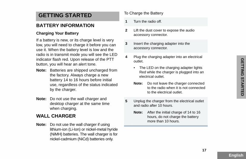
GETTING STARTED
BATTERY INFORMATION
Charging Your Battery
To Charge the Battery
1 Turn the radio off.
2 Lift the dust cover to expose the audio onnector.
harging adapter into the onnector.
arging adapter into an electrical
on the charging adapter lights ile the charger is plugged into an l outlet.
not leave the charger connected the radio when it is not connected the electrical outlet.
charger from the electrical outlet fter 10 hours.
er the initial charge of 14 to 16 urs, do not charge the battery re than 10 hours.
03_GetStarted.fm Page 17 Monday, November 17, 2003 1:56 PM
If a battery is new, or its charge level is very low, you will need to charge it before you can use it. When the battery level is low and the radio is in transmit mode you will see the LED indicator flash red. Upon release of the PTT button, you will hear an alert tone.
Note: Batteries are shipped uncharged from the factory. Always charge a new battery 14 to 16 hours before initial use, regardless of the status indicated by the charger.
Note: Do not use the wall charger and desktop charger at the same time when charging.
WALL CHARGER
Note: Do not use the wall charger if using lithium-ion (Li-Ion) or nickel-metal hyride (NiMH) batteries. The wall charger is for nickel-cadmium (NiCd) batteries only.
accessory c
3 Insert the caccessory c
4 Plug the choutlet.
• The LEDRed whelectrica
Note: Doto to
5 Unplug the and radio a
Note: Afthomo
En
GE
TT
ING
ST
AR
TE
D
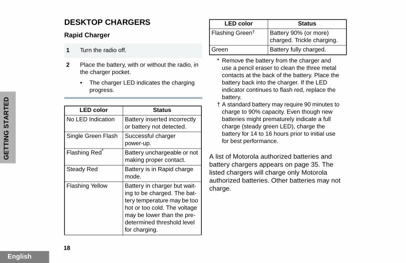
DESKTOP CHARGERS
Rapid Charger
torola authorized batteries and rgers appears on page 35. The ers will charge only Motorola batteries. Other batteries may not
1 Turn the radio off.
Flashing Green† Battery 90% (or more) charged. Trickle charging.
Green Battery fully charged.
the battery from the charger and ncil eraser to clean the three metal at the back of the battery. Place the
back into the charger. If the LED r continues to flash red, replace the
ard battery may require 90 minutes to to 90% capacity. Even though new s might prematurely indicate a full (steady green LED), charge the for 14 to 16 hours prior to initial use performance.
LED color Status
03_GetStarted.fm Page 18 Monday, November 17, 2003 1:56 PM
18glish
A list of Mobattery chalisted chargauthorized charge.
2 Place the battery, with or without the radio, in the charger pocket.
• The charger LED indicates the charging progress.
LED color Status
No LED Indication Battery inserted incorrectly or battery not detected.
Single Green Flash Successful charger power-up.
Flashing Red* Battery unchargeable or not making proper contact.
Steady Red Battery is in Rapid charge mode.
Flashing Yellow Battery in charger but wait-ing to be charged. The bat-tery temperature may be too hot or too cold. The voltage may be lower than the pre-determined threshold level for charging.
* Removeuse a pecontactsbattery indicatobattery.
† A standcharge batteriecharge battery for best
19English
GE
TT
ING
ST
AR
TE
D
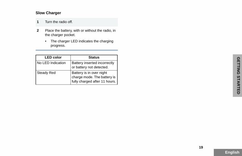
Slow Charger
1 Turn the radio off.
2 Place the battery, with or without the radio, in
03_GetStarted.fm Page 19 Monday, November 17, 2003 1:56 PM
the charger pocket.
• The charger LED indicates the charging progress.
LED color Status
No LED Indication Battery inserted incorrectly or battery not detected.
Steady Red Battery is in over night charge mode. The battery is fully charged after 11 hours.
En
GE
TT
ING
ST
AR
TE
D
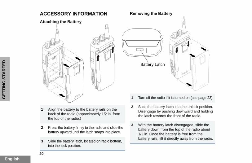
ACCESSORY INFORMATION
Attaching the Battery
Removing the Battery
radio if it is turned on (see page 23).
attery latch into the unlock position. by pushing downward and holding wards the front of the radio.
ttery latch disengaged, slide the n from the top of the radio about
e the battery is free from the s, lift it directly away from the radio.
atch
03_GetStarted.fm Page 20 Monday, November 17, 2003 1:56 PM
20glish
1 Align the battery to the battery rails on the back of the radio (approximately 1/2 in. from the top of the radio.)
2 Press the battery firmly to the radio and slide the battery upward until the latch snaps into place.
3 Slide the battery latch, located on radio bottom, into the lock position.
1 Turn off the
2 Slide the bDisengagethe latch to
3 With the babattery dow1/2 in. Oncbattery rail
Battery L
21English
GE
TT
ING
ST
AR
TE
D
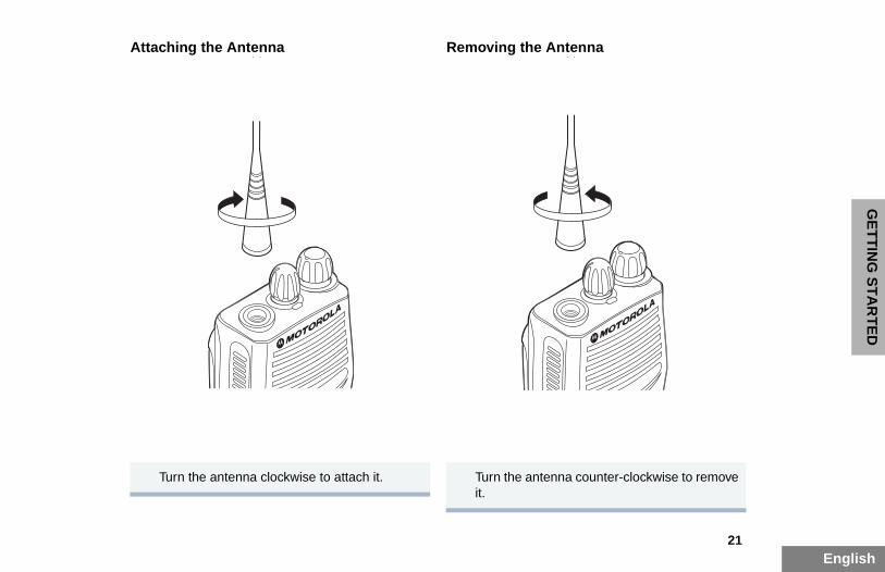
Attaching the Antenna Removing the Antenna
ntenna counter-clockwise to remove
03_GetStarted.fm Page 21 Monday, November 17, 2003 1:56 PM
Turn the antenna clockwise to attach it. Turn the ait.
En
GE
TT
ING
ST
AR
TE
D
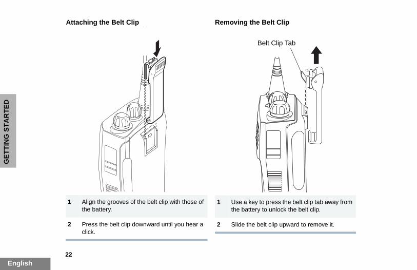
Attaching the Belt Clip Removing the Belt Clip
key to press the belt clip tab away from tery to unlock the belt clip.
e belt clip upward to remove it.
Belt Clip Tab
03_GetStarted.fm Page 22 Monday, November 17, 2003 1:56 PM
22glish
1 Align the grooves of the belt clip with those of the battery.
2 Press the belt clip downward until you hear a click.
1 Use a the bat
2 Slide th

23English
GE
TT
ING
ST
AR
TE
D
TURNING THE RADIO ON OR OFF ADJUSTING THE VOLUME
G A RADIO CHANNEL
ers 4 or 16 channels.
o government regulations, some els may not be programmed. Ask
dealer for more information.
annel, turn the Channel b clockwise or counterclockwise h the desired channel.
1 Hold down the Volume Set button (see page 14); you will hear a continuous tone.
On/Off/Volume Control knob to the volume level.
the Volume Set button.
03_GetStarted.fm Page 23 Monday, November 17, 2003 1:56 PM
SELECTIN
Your radio off
Note: Due tchannyour
To select a chSelector knountil you reac
Turn the On/Off/Volume Control knob clockwise. If power-up is successful, you will hear the Self-Test Pass Tone ( ) and see the LED flash green.
If the radio fails to power up, you will hear the Self Test Fail Tone ( ).
Turn the On/Off/Volume Control knob counter-clockwise until you hear a click.
ON OFF
2 Turn thedesired
3 Release
En
GE
TT
ING
ST
AR
TE
D
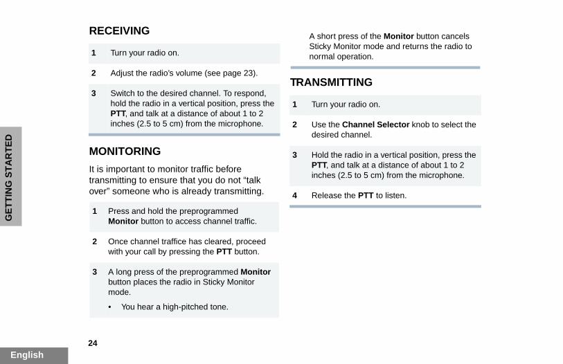
RECEIVING
ITTING
1 Turn your radio on.
A short press of the Monitor button cancels Sticky Monitor mode and returns the radio to normal operation.
ur radio on.
e Channel Selector knob to select the channel.
e radio in a vertical position, press the nd talk at a distance of about 1 to 2 (2.5 to 5 cm) from the microphone.
e the PTT to listen.
03_GetStarted.fm Page 24 Monday, November 17, 2003 1:56 PM
24glish
MONITORING
It is important to monitor traffic before transmitting to ensure that you do not “talk over” someone who is already transmitting.
TRANSM2 Adjust the radio’s volume (see page 23).
3 Switch to the desired channel. To respond, hold the radio in a vertical position, press the PTT, and talk at a distance of about 1 to 2 inches (2.5 to 5 cm) from the microphone.
1 Press and hold the preprogrammed Monitor button to access channel traffic.
2 Once channel traffice has cleared, proceed with your call by pressing the PTT button.
3 A long press of the preprogrammed Monitor button places the radio in Sticky Monitor mode.
• You hear a high-pitched tone.
1 Turn yo
2 Use thdesired
3 Hold thPTT, ainches
4 Releas
25English
GE
TT
ING
ST
AR
TE
D
VOX OPERATION
When hands-free operation is desired, your radio can be activated by voice alone using the VOX feature when you speak through an
You can select channels to enable or disable VOX as preprogrammed by your dealer.
ABLE HEADSET
program your radio so you can through a headset while you
1 Select a channel that has been preprogrammed by your dealer to enable
ssing the PTT button disables X.
annel that has not been med by your dealer to disable
r radio.
VOX accessory to your radio.
io on. During transmit, you will oice through the headset while
03_GetStarted.fm Page 25 Monday, November 17, 2003 1:56 PM
accessory that is connected to your radio.
Connecting a VOX Headset
Enabling or Disabling VOX
To enable or disable VOX operation, press the preprogrammed VOX button (see page 14).
Note: Pressing the PTT button disables VOX.
– or –
ENABLE/DISSIDETONE
Your dealer canhear your voicespeak.
VOX Headset
1 Turn off your radio.
2 Connect the VOX accessory to your radio and turn the radio on.
VOX.
Note: PreVO
2 Select a chpreprogramVOX.
1 Turn off you
2 Connect the
3 Turn the radhear your vyou speak.
En
GE
TT
ING
ST
AR
TE
D
Non-VOX Headset with In-Line PTT
REPEATER OR TALKAROUND MODE
Talkaround Mode enables you to communicate r radio when either:
ater is not operating
io is out of the repeater’s range but mmunicating distance of another
reprogrammed Repeater/ button (see page 14) to toggle peater mode and Talkaround Mode.
TIGHT OR NORMAL H
ture to filter out nuisance (unwanted) background noise. However, uelch could cause calls from remote
be filtered out as well. In this case, lch may be more desirable.
reprogrammed Squelch button 4) to toggle between tight and
elch.
4 To disable the headset sidetone, turn off your radio and turn the radio on again.
03_GetStarted.fm Page 26 Monday, November 17, 2003 1:56 PM
26glish
with anothe
• the repe
– or –
• your radwithin coradio.
Press the pTalkaroundbetween Re
SETTINGSQUELC
Use this feacalls and/or tightening sqlocations to normal sque
Press the p(see page 1normal squ
1 Turn off your radio.
2 Connect the non-VOX accessory to your radio.
3 Press and hold the In-line PTT on your headset.
4 Turn the radio on and release the PTT once the radio has completed start-up. During transmit, you will hear your voice through the headset while you speak.
5 To disable the headset sidetone, turn off your radio and turn the radio on again.
27English
GE
TT
ING
ST
AR
TE
D
SETTING THE POWER LEVEL(Available for 4W and 5W models only)
Each channel in your radio has a predefined transmit power level that can be changed.
03_GetStarted.fm Page 27 Monday, November 17, 2003 1:56 PM
• High power allows you to reach a radio that is farther away.
• Low power conserves the battery’s charge.
Press the preprogrammed Power Level button (see page 14) to toggle between low and high power.

En
GE
TT
ING
ST
AR
TE
D
Notes:
03_GetStarted.fm Page 28 Monday, November 17, 2003 1:56 PM
28glish
29English
RA
DIO
CA
LL
S
RADIO CALLS
RECEIVING A SELECTIVE CALL(Available for 4W and 5W models only)
04_RadioCall.fm Page 29 Monday, November 17, 2003 1:57 PM
When you receive a Selective Call:
• The LED indicator flashes yellow, if pro-grammed by your dealer.
• You hear two high pitched tones.
RECEIVING A CALL ALERT PAGE(Available for 4W and 5W models only)
When you receive a Call Alert page:
• The LED indicator flashes yellow, if pro-grammed by your dealer.
• You hear four high pitched tones.
To acknowledge the page, press and release the PTT button; to cancel the page, press any other key.
1 To acknowledge the call, press and release the PTT button.
2 Press and hold the PTT button to talk; release to listen.

En
RA
DIO
CA
LL
S
Notes:
04_RadioCall.fm Page 30 Monday, November 17, 2003 1:57 PM
30glish
31English
SC
AN
SCAN
Your radio is equipped with the Scan feature, which allows you to monitor multiple channels
Note: The LED scan indicator stops blinking while the radio is in hangtime. If the PTT button is not pressed during the preprogrammed hangtime, the radio returns to scanning channels.
YSTEM SCAN
ogrammed Scan button (see
YSTEM SCAN
ogrammed Scan button.
UTO SCAN
matically starts scanning once uto Scan enabled is selected.
nel that your dealer has for Auto Scan.
UTO SCAN
l that has not been for Auto Scan.
05_Scan.fm Page 31 Monday, November 17, 2003 1:57 PM
for voice activity. The radio will stop on a channel when it detects activity on it.
Your radio automatically switches to a channel within the scan list when it detects activity.
The LED indicator blinks green during a scan operation and stops blinking when the radio switches to a channel.
There are two types of Scan available in your radio:
• System Scan
• Auto Scan
TALKBACK
The Talkback feature allows you to respond to a transmission while scanning. If a transmission is detected on a channel while scanning, the radio will stop on that channel for a default period of time after activity has ceased. This is referred to as “hangtime”. During this hangtime you may respond by pressing the PTT button.
STARTING S
Press the preprpage 14).
STOPPING S
Press the prepr
STARTING A
Auto Scan autoa channel with A
Select the chanpreprogrammed
STOPPING A
Select a channepreprogrammed
En
SC
AN
DELETING A NUISANCE CHANNEL
Note: Your dealer must preprogram a button to Nuisance Delete (see page 14) to access this feature.
Restoring a Channel to the Scan List
1 Power off the radio. Once the radio is powered on again, the deleted nuisance channels are restored to the scan list.
preprogrammed Scan button to stop
preprogrammed Scan button again anning again. The Deleted Nuisance are restored to the scan list.
ifferent channel. Once you return to al channel, the deleted nuisance are restored to the scan list.
05_Scan.fm Page 32 Monday, November 17, 2003 1:57 PM
32glish
If a channel continually generates unwanted calls or noise (a “nuisance” channel), you can temporarily remove it from the scan list:
1 While the radio is on the Nuisance Channel, press the preprogrammed Nuisance Channel Delete button until you hear a tone.
2 Release the Nuisance Channel Delete button. The nuisance channel is deleted.
Note: You cannot temporarily delete the channel that has been prepro-grammed as your designated scan channel, a priority channel, or the last remaining channel in the scan list.
– or –
1 Press thethe scan.
2 Press theto start scChannels
– or –
1 Select a dthe originchannels
33English
SC
AN
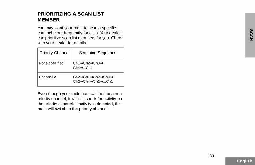
PRIORITIZING A SCAN LIST MEMBER
You may want your radio to scan a specific channel more frequently for calls. Your dealer
05_Scan.fm Page 33 Monday, November 17, 2003 1:57 PM
can prioritize scan list members for you. Check with your dealer for details.
Even though your radio has switched to a non-priority channel, it will still check for activity on the priority channel. If activity is detected, the radio will switch to the priority channel.
Priority Channel Scanning Sequence
None specified Ch1➠ Ch2➠ Ch3➠
Ch4➠ ...Ch1
Channel 2 Ch2➠ Ch1➠ Ch2➠ Ch3➠
Ch2➠ Ch4➠ Ch2➠ ...Ch1

En
SC
AN
Notes:
05_Scan.fm Page 34 Monday, November 17, 2003 1:57 PM
34glish
35English
AC
CE
SS
OR
IES
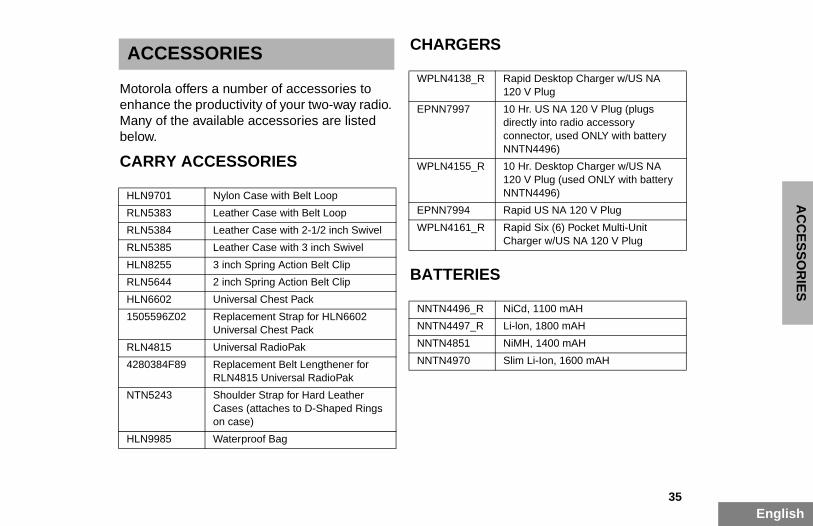
ACCESSORIES
Motorola offers a number of accessories to enhance the productivity of your two-way radio.
CHARGERS
S
WPLN4138_R Rapid Desktop Charger w/US NA 120 V Plug
EPNN7997 10 Hr. US NA 120 V Plug (plugs directly into radio accessory connector, used ONLY with battery NNTN4496)
10 Hr. Desktop Charger w/US NA 120 V Plug (used ONLY with battery NNTN4496)
Rapid US NA 120 V Plug
Rapid Six (6) Pocket Multi-Unit Charger w/US NA 120 V Plug
NiCd, 1100 mAH
Li-lon, 1800 mAH
NiMH, 1400 mAH
Slim Li-Ion, 1600 mAH
06_Accessory.fm Page 35 Monday, December 1, 2003 3:21 PM
Many of the available accessories are listed below.
CARRY ACCESSORIES
BATTERIE
HLN9701 Nylon Case with Belt Loop
RLN5383 Leather Case with Belt Loop
RLN5384 Leather Case with 2-1/2 inch Swivel
RLN5385 Leather Case with 3 inch Swivel
HLN8255 3 inch Spring Action Belt Clip
RLN5644 2 inch Spring Action Belt Clip
HLN6602 Universal Chest Pack
1505596Z02 Replacement Strap for HLN6602 Universal Chest Pack
RLN4815 Universal RadioPak
4280384F89 Replacement Belt Lengthener for RLN4815 Universal RadioPak
NTN5243 Shoulder Strap for Hard Leather Cases (attaches to D-Shaped Rings on case)
HLN9985 Waterproof Bag
WPLN4155_R
EPNN7994
WPLN4161_R
NNTN4496_R
NNTN4497_R
NNTN4851
NNTN4970

En
AC
CE
SS
OR
IES
HEADSETS
ILLANCE ACCESSORIES
RLN5411 Ultra-Lite Breeze Behind the Head Headset
RKN4090 Adapter Cable (for use with headset RMN5015)
RKN4094 In-Line PTT Adapter (for use with headset RMN4051)
Replacement Foam Ear Pad and Windscreen Kit (for use with headsets RMN9013 & RMN4016)
34 Replacement Ear Seals (for use with headsets HMN9021 & HMN9022)
66 Replacement Ear Pad (for use with headset BDN6647)
59 Replacement Wind Screen (for use with headset BDN6647)
Earpiece with Volume Control, 1-Wire (plastic earloop) (Beige)
Earpiece without Volume Control, 1-Wire (plastic earloop) (Beige)
Earpiece without Volume Control, 1-Wire (plastic earloop) (Black)
Earpiece with Microphone & PTT Combined, 2-Wire (Beige)
Earpiece with Microphone & PTT Combined, 2-Wire (Black)
06_Accessory.fm Page 36 Monday, December 1, 2003 3:21 PM
36glish
SURVE
PMMN4001 Ultra-Lite Earset with Mic and PTT
HMN9013 Lightweight Headset w/o In-line PTT
RMN4016 Lightweight Headset with In-line PTT
RLN5238 Lightweight Headset with In-line PTT, NFL Style
HMN9021 Medium Weight Over the Head Dual Muff Headset
HMN9022 Medium Weight Behind the Head Dual Muff Headset
BDN6647 Medium Weight Single Speaker Headset
BDN6648 Heavy Duty Dual Muff Headset with Noise Canceling Microphone
RMN5015 Heavy Duty Dual Muff Racing Headset (requires RKN4090 Headset Adapter Cable)
RMN4051 2-Way Hard Hat Mount, Black, Noise Reduction Rating (22 dB) (requires RKN4094)
RMN4054 Receive-Only Hard Hat Mount Headset w/3.5mm Right Angle Plug
RMN4055 Receive-Only Headband Style Headset w/3.5mm Right Angle Plug
REX4648
7580376E
5080371E
3580371E
HMN9752
HMN9727
RLN4894
HMN9754
RLN4895
37English
AC
CE
SS
OR
IES
PEAKER MICROPHONES
OPHONE SYSTEMS
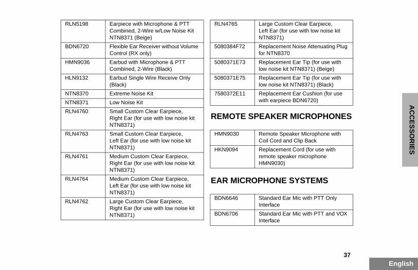
RLN5198 Earpiece with Microphone & PTT Combined, 2-Wire w/Low Noise Kit NTN8371 (Beige)
BDN6720 Flexible Ear Receiver without Volume Control (RX only)
RLN4765 Large Custom Clear Earpiece,Left Ear (for use with low noise kit NTN8371)
5080384F72 Replacement Noise Attenuating Plug for NTN8370
Replacement Ear Tip (for use with low noise kit NTN8371) (Beige)
Replacement Ear Tip (for use with low noise kit NTN8371) (Black)
Replacement Ear Cushion (for use with earpiece BDN6720)
Remote Speaker Microphone with Coil Cord and Clip Back
Replacement Cord (for use with remote speaker microphone HMN9030)
Standard Ear Mic with PTT Only Interface
Standard Ear Mic with PTT and VOX Interface
06_Accessory.fm Page 37 Monday, December 1, 2003 3:21 PM
REMOTE S
EAR MICR
HMN9036 Earbud with Microphone & PTT Combined, 2-Wire (Black)
HLN9132 Earbud Single Wire Receive Only (Black)
NTN8370 Extreme Noise Kit
NTN8371 Low Noise Kit
RLN4760 Small Custom Clear Earpiece,Right Ear (for use with low noise kit NTN8371)
RLN4763 Small Custom Clear Earpiece,Left Ear (for use with low noise kit NTN8371)
RLN4761 Medium Custom Clear Earpiece, Right Ear (for use with low noise kit NTN8371)
RLN4764 Medium Custom Clear Earpiece,Left Ear (for use with low noise kit NTN8371)
RLN4762 Large Custom Clear Earpiece,Right Ear (for use with low noise kit NTN8371)
5080371E73
5080371E75
7580372E11
HMN9030
HKN9094
BDN6646
BDN6706
En
AC
CE
SS
OR
IES
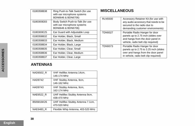
MISCELLANEOUS0180358B38 Ring Push-to-Talk Switch (for use with ear microphone systems BDN6646 & BDN6706)
0180300E83 Body Switch Push-to-Talk (for use with ear microphone systems
RLN5500 Accessory Retainer Kit (for use with any audio accessory that needs to be secured to the radio due to demanding customer environments)
Portable Radio Hanger for door panels up to 2.75 inch (slides over and hangs from the door panel in vehicle, radio belt clip required)
Portable Radio Hanger for door panels up to 2.75 to 3.25 inch (slides over and hangs from the door panel in vehicle, radio belt clip required)
06_Accessory.fm Page 38 Monday, December 1, 2003 3:21 PM
38glish
ANTENNAS
BDN6646 & BDN6706)
0180300E25 Ear Guard with Adjustable Loop
0180358B32 Ear Holder, Black, Small
0180358B33 Ear Holder, Black, Medium
0180358B34 Ear Holder, Black, Large
0180358B35 Ear Holder, Clear, Small
0180358B36 Ear Holder, Clear, Medium
0180358B37 Ear Holder, Clear, Large
NAD6502_R VHF Heliflex Antenna 14cm, 146-174 MHz
HAD9742 VHF Stubby Antenna, 9cm,146-162 MHz
HAD9743 VHF Stubby Antenna, 9cm,162-174 MHz
NAE6522_R UHF Heliflex Stubby Antenna 9cm, 438-470 MHz
8505816K26 UHF Heliflex Stubby Antenna 7.1cm,470-520 MHz
NAE6483_R Flexible Whip Antenna, 403-520 MHz
TDN9327
TDN9373
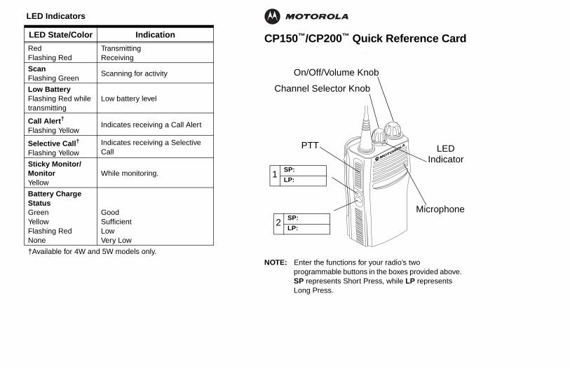
CP150™/CP200™ Quick Reference Card
NOTE: Enter the functions for your radio’s two programmable buttons in the boxes provided above. SP represents Short Press, while LP represents Long Press.
LED Indicators
LED State/Color Indication
RedFlashing Red
TransmittingReceiving
ScanFlashing Green
Scanning for activity
Low BatteryFlashing Red while transmitting
Low battery level
Call Alert†
Flashing YellowIndicates receiving a Call Alert
Selective Call†
Flashing YellowIndicates receiving a Selective Call
Sticky Monitor/MonitorYellow
While monitoring.
Battery Charge StatusGreenYellowFlashing RedNone
GoodSufficientLowVery Low
†Available for 4W and 5W models only.
Microphone
PTT
2SP:
LP:
1SP:
LP:
LEDIndicator
Channel Selector Knob
On/Off/Volume Knob
QR-Card.fm Page 39 Monday, November 17, 2003 1:58 PM
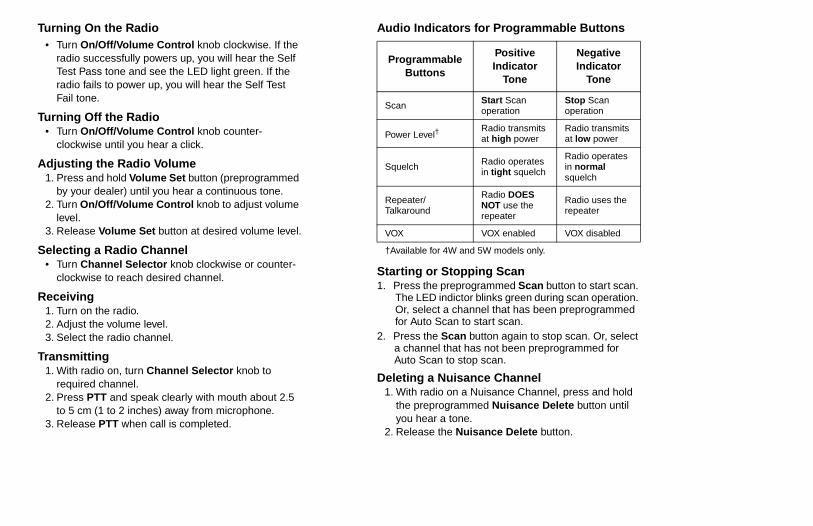
Turning On the Radio• Turn On/Off/Volume Control knob clockwise. If the
radio successfully powers up, you will hear the Self Test Pass tone and see the LED light green. If the radio fails to power up, you will hear the Self Test Fail tone.
Turning Off the Radio• Turn On/Off/Volume Control knob counter-
clockwise until you hear a click.
Audio Indicators for Programmable Buttons
ping Scangrammed Scan button to start scan. r blinks green during scan operation. nnel that has been preprogrammed start scan.
button again to stop scan. Or, select as not been preprogrammed for
op scan.
nce Channel Nuisance Channel, press and hold med Nuisance Delete button until .isance Delete button.
Programmable Buttons
Positive Indicator
Tone
Negative Indicator
Tone
Scan Start Scan operation
Stop Scan operation
Power Level†Radio transmits at high power
Radio transmits at low power
Radio operates in tight squelch
Radio operates in normal squelch
Radio DOES NOT use the repeater
Radio uses the repeater
VOX enabled VOX disabled
d 5W models only.
QR-Card.fm Page 40 Monday, November 17, 2003 1:58 PM
Adjusting the Radio Volume1. Press and hold Volume Set button (preprogrammed
by your dealer) until you hear a continuous tone.2. Turn On/Off/Volume Control knob to adjust volume
level.3. Release Volume Set button at desired volume level.
Selecting a Radio Channel• Turn Channel Selector knob clockwise or counter-
clockwise to reach desired channel.
Receiving1. Turn on the radio.2. Adjust the volume level.3. Select the radio channel.
Transmitting1. With radio on, turn Channel Selector knob to
required channel.2. Press PTT and speak clearly with mouth about 2.5
to 5 cm (1 to 2 inches) away from microphone.3. Release PTT when call is completed.
Starting or Stop1. Press the prepro
The LED indictoOr, select a chafor Auto Scan to
2. Press the Scana channel that hAuto Scan to st
Deleting a Nuisa1. With radio on a
the preprogramyou hear a tone
2. Release the Nu
Squelch
Repeater/Talkaround
VOX
†Available for 4W an

MOTOROLA, the Stylized M Logo, and Radius are registered in the US Patent & Trademark Office.All other product or service names are the property of their respective owners. © Motorola, Inc. 2002, 2003. All rights reserved. Printed in U.S.A.
MOTOROLA, le logotype au M stylisé et Radius sont enregistrés auprès du Bureau des marques et brevets des États-Unis.Tous les autres noms de produits et de services sont la propriété de leurs titulaires respectifs.© Motorola, Inc. 2002, 2003. Tous droits réservés. Imprimé aux États-Unis.
*6880309N60*6880309N60-A
CP150™/CP200™
Commercial SeriesTwo-Way Radio User Guide
Manuel de l'utilisateurde la radio bidirectionnelle
309N60-A_cvr.qxd 8/19/2003 10:43 AM Page 1