CMHC Best Practice Guide—Brick Veneer Steel Stud
99
Building Technology – BVSS CMHC offers a wide range of housing-related information. For details, contact your local CMHC office or call 1-800-668-2642. Cette publication est aussi disponible en français sous le titre : Ossature en acier et placage de brique – LNH 6916 BEST PRACTICE GUIDE BUILDING TECHNOLOGY BRICK VENEER STEEL STUD
Transcript of CMHC Best Practice Guide—Brick Veneer Steel Stud
Building Technology – BVSS
CMHC offers a wide range of housing-related information. For details, contact your local CMHC office or call 1-800-668-2642.
Cette publication est aussi disponible en français sous le titre : Ossature en acier et placage de brique – LNH 6916
BEST PRACTICE GUIDE
BUILDING TECHNOLOGY
BRICKVENEER
STEEL STUD
Building Technology – BVSS
Canadian Cataloguing in Publication Data
Posey, James B.
Brick veneer steel stud
(Best practice guide: building technology)Issued also in French under title: Ossatureen acier et placage de brique.Running title: Building technology – BVSS.Includes bibliographical references.ISBN 0-660-16532-5Cat. no. NH15-132/1996E
1. Exterior walls – Design and Construction.2. Exterior walls – Thermal properties.I. Little, Andrew, 1946- .II. Canada Mortgage and Housing Corporation.III. Title: Building technology – BVSS.IV. Title.V. Series.
TH2235.P67 1996 690’.12 C96-980305-2
© 1996 Canada Mortgage and Housing Corporation
Printed in CanadaProduced by CMHC
Building Technology – BVSS
CMHC STATEMENT
Canada Mortgage and HousingCorporation, the Federal Government’s housing agency, is responsible foradministering the National Housing Act.
This legislation is designed to aid in theimprovement of housing and living conditions in Canada. As a result, thecorporation has interests in all aspects of housing and urban growth anddevelopment.
Under Part IX of this Act, the Governmentof Canada provides funds to CMHC to conduct research into the social,economic, and technical aspects of housing and related fields, and toundertake the publishing and distribution of the results of this research.CMHC therefore has a statutory responsibility to make widely availableinformation that may be useful in the improvement of housing and livingconditions.
This publication is one of the many itemsof information published by CMHC with the assistance of federal funds.
ACKNOWLEDGEMENTS
This guide was prepared for the High RiseInnovation Centre, Canada Mortgage and Housing Corporation by JamesB. Posey, Posey Construction Specifications. Drawings were prepared byAndrew Little, BArch, MRAIC, Andrew Little Architect. The advice andassistance of CMHC Project Managers Jacques Rousseau and SandraMarshall, and of T.W.J. Trestain, PEng, and Dr. M. Hatzinikolas isgratefully acknowledged.
Disclaimer
This guide was prepared by PoseyConstruction Specifications and Andrew Little Architect for CMHC. Theanalysis, interpretations, and recommendations are those of the consultantsand do not necessarily reflect the views of CMHC or those divisions of thecorporation that assisted in preparation and publication.
Care has been taken to review the researchsummarized in this guide, but no attempt has been made to replicate orcheck experimental results or validate computer programs. Neither theauthors nor CMHC warrant or assume any liability for the accuracy orcompleteness of the text, drawings, or accompanying C D - R O M , or theirfitness for any particular purpose. It is the responsibility of the user toapply professional knowledge in the use of the information contained inthese drawings, specifications, and texts, to consult original sources, orwhen appropriate, to consult an architect or engineer.
Building Technology – BVSS
i
1 / INTRODUCTION
Purpose 1-1Background 1-3
Advantages 1-4Limitations 1-4Historical Basis for Design 1-5Evolution and Improvement 1-6Simplifications, Shortcuts, and Oversights 1-6False Alarms? 1-7
Future Design 1-8
2 / BUILDING SCIENCE ISSUES
Exclusion of Exterior Water 2-1Pressure Equalization 2-2
Heat Flow and Thermal Bridging 2-3
Air Leakage, Vapour Diffusion, and Condensation 2-4
Inaccuracy and Variation in Position 2-6Concrete 2-6Structural Steel 2-7Masonry 2-8Field Experience 2-8
3 / CMHC RESEARCH FINDINGS
User Survey and Field Observations 3-1
Laboratory Studies 3-2Tests of Strength and Stiffness of Components and Connections 3-2Tests of Water Permeability of Cracked Masonry Veneer 3-5Small Scale Tests with Temperature, Air Pressure, and Vapour Pressure Differentials 3-5Tests of Brick Ties With Steel Studs 3-7Full Scale Tests with Simulation of Wind and Rain 3-10Summary of McMaster Results 3-11CMHC Research Project Testing of Air Barriers Construction Details 3-12
Conceptual Studies 3-12Structural Requirements for Air Barriers 3-12Finite Element Models 3-15RAIN 3-16EMPTIED 3-16
Other Sources of Information 3-17
table of contents
table of contents Building Technology – BVSS
ii
4 / DESIGN IMPLICATIONS
Face Seal Systems 4-1
Drain Screen Systems 4-1
Rain Screen Systems 4-2
Condensation in Sheathing 4-4Condensation in Brick Veneer 4-6
Displacement at Supports 4-7
Tolerances 4-8Concrete 4-8Steel and Miscellaneous Metal 4-8Masonry 4-8Steel Studs 4-8
The Last Word? 4-9
Application 4-9
5 / QUALITY ASSURANCE
Commissioning 5-1Prototype 5-1Mock-up 5-1Ongoing Inspection 5-2Final Inspection 5-2Compliance Testing 5-2
6 / DETAILS AND SPECIFICATIONS
CAD Drawing Files 6-1
Building Frame 6-1
Thermal and Moisture Protection 6-1
Provision for Movement 6-2
Shelf Angle 6-3
Brick Ties 6-3
Cavity 6-4
Structural Considerations 6-5
Detail 1 - SLAB EDGE 6-5Tolerances 6-5Slab Edge Insulation 6-6Ties 6-6Flashing 6-6Fastening of Stud Track 6-6
Detail 2 - WARM LEDGER AND STUD CONNECTOR 6-8
Shelf Angle 6-8Stud Top Connector 6-8Flashing 6-8
Detail 3 - WINDOW HEAD AND SILL 6-10
Lintel 6-10Window Position 6-10Sill 6-10Stool 6-10
Building Technology – BVSS
iii
Detail 4 - WINDOW AT U/S SLAB 6-12
Detail 5 - WINDOW JAMB 6-14
Detail 6 - LOW PARAPET 6-16Shelf Angle 6-16Insulation 6-16Support 6-16Compartmentation 6-16Flashing 6-16Roofing 6-18
Detail 7 - SLAB EDGE AT FOUNDATION 6-18
Detail 8 - BALCONY AT PATIO DOOR 6-20
Curb 6-20Drips 6-20Perimeter Fastening of Air Barrier 6-20
Detail 9 - CORNER 6-22
Corner Compartments 6-22Fastening at Sides 6-22Alignment 6-22Sealing Dividers 6-22
Detail 10 - CONTROL JOINT 6-24
Detail 11 - COLD SOFFIT 6-26
Detail 12 - EXHAUST VENT 6-28
Detail 13 - CURTAIN WALL JAMB, SILL AND SLAB 6-30
Specifications 6-32Division 4 Masonry 6-32Division 7 Thermal and Moisture Protection 6-32Section 05410 Lateral Load-bearing Steel Stud Framing 6-32Section 09250 Gypsum Board 6-33Coordination of Specification Sections 6-33
Files on CD-ROM 6-34Drawing Files 6-34Specification Files 6-34
REFERENCES
References R-1
APPENDIX: Guide Specification
05410 Lateral Load-bearing Steel Stud Framing A-1
table of contents
CHAPTER 1
INTRODUCTION
Building Technology – BVSS
1-1
Purpose
Recent research has extended availableknowledge of the performance of brick veneer steel stud (or BVSS) walls.The purpose of this guide is to distill the findings of recent research, withemphasis on building science issues and CMHC sponsored research, and toconsolidate this information in an accessible form for building designers.
The guide does not attempt to addressstructural design of BVSS walls per se. Structural aspects are discussedonly because structural decisions have impacts on architectural andbuilding science aspects of wall design that might otherwise beoverlooked. Readers whose primary interest is structural design shouldrefer to the original research reports as well as sources of information ondesign procedures, such as the CSSBI Lightweight Steel Framing DesignManual. This guide places greater emphasis on traditionally architecturalaspects of building science.
The CSSBI Lightweight Steel FramingManual provides the following checklist of building science issues:
• rain screens;
• air spaces in walls free of debris;
• flashing and weep holes;
• insulation;
• protection from condensation and water penetration for exterior sheathingsthat deteriorate in strength and stiffness in the presence of moisture;
• insulation detailing to minimize thermal bridging;
• continuous air barrier systems incorporating well sealed joints;
• vapour retarders that may or may not be integral with the air barrier;
• fire resistance;
• detailing to minimize sound transmission;
• detailing to accommodate building frame movements;
• detailing to accommodate thermal movements of large panels;
• in masonry veneer construction, brick ties with corrosion protection,required stiffness and strength and with adequate connection to the steelstuds.
These issues are addressed in this guide ingreater detail, except for fire resistance and sound transmission. Insulationis dealt with only insofar as it affects durability of the wall, as opposed toenergy consumption.
Chapter 6 provides sample details andmaster specifications to facilitate the application of suggestedimprovements.
The focus is on control of flows ofmoisture, air, and heat. These factors, if not addressed, will compromisedurability and maintenance of satisfactory interior conditions. Where theyinteract with structural design, the guide discusses criteria to consider instructural design, to ensure satisfactory architectural performance.Questions about how much insulation to use for energy conservation or lifecycle cost, fire resistance, acoustic control, and aesthetics are notaddressed.
From the literature, it appears that someaspects of BVSS wall design are controversial, and that problems mayexist for which there are no generally accepted and well-tried solutions.The guide does not pave a single path to good BVSS wall design. Itprovides new tools that designers can use to pave their own paths. Everyproject, with its own environmental loads, structure, and budget, will callfor different design choices, and result in details different from the detailsillustrated. The issues raised, research results, and suggested analyticaltools, however, will all apply to a broad spectrum of designs.
Steel stud exterior walls have receivedcriticism, particularly as backup for masonry veneer. At the same time,their low cost, small footprint, and light weight are attractivecharacteristics.
The most common problems of steel studexterior walls derive from an inability to exclude moisture and therebyprevent corrosion and other deterioration. Rain is the most obvious source.However, air leakage resulting in condensation is a common if less obviouscause. Thermal bridging and localized heat loss often result indiscolouration, or even condensation, on interior surfaces at stud locationsof walls insulated only within the stud space. Structural problems, whenthey occur, typically appear as distress in veneer and finishes. They mayincrease air leakage and rain penetration, or impair appearance, but rarelyaffect safety, except in the long term, when corrosion results.
The design conditions specified by codesseldom occur in service, and never occur during the useful lifetimes ofmany buildings. Subjecting full size samples of wall assemblies to theextremes of their design service conditions is the only way to hasten thediscovery of unexpected design problems. The details in Chapter 6 takeinto account the experience gained from several CMHC sponsored testprograms conducted to simulate extreme service conditions.
Some problems associated with BVSSwalls have nothing to do with the steel stud framing. Brick spalling as aresult of inadequate allowance for creep shortening and deflection of thebuilding frame can happen with any backup wall. If tolerances are notcoordinated to provide enough latitude for unavoidable dimensionalinaccuracies, the builder will be forced to improvise alternative details.Any wall may suffer from condensation damage or rain penetration, if notdesigned to avoid them.
INTRODUCTION Building Technology – BVSS
1-2
Building Technology – BVSS
1-3
Background
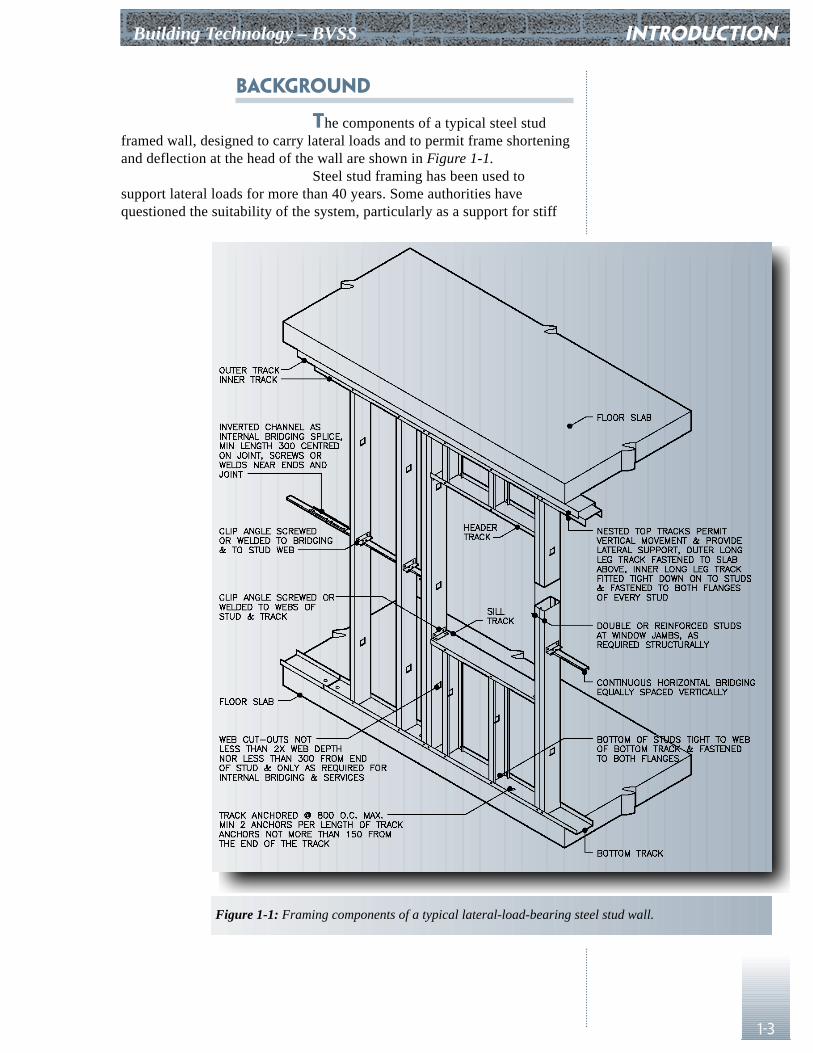
The components of a typical steel studframed wall, designed to carry lateral loads and to permit frame shorteningand deflection at the head of the wall are shown in Figure 1-1.
Steel stud framing has been used tosupport lateral loads for more than 40 years. Some authorities havequestioned the suitability of the system, particularly as a support for stiff
INTRODUCTION
Figure 1-1: Framing components of a typical lateral-load-bearing steel stud wall.
INTRODUCTION Building Technology – BVSS
1-4
exterior cladding. In a recent survey done for CMHC1, respondentsclassified themselves as:
• users with reservations 60% (mostly designers);
• enthusiastic users 20% (mostly contractors);
• non-believers 10%;
• open minded non-users 10%.
While in retrospect it may seem thatextensive use of steel studs preceded extensive analysis and research, steelstuds were originally designed by applying familiar procedures. We shouldbe surprised if 40 years of service and testing failed to reveal room forimprovement.
Some modifications have become commonas a result of published field and laboratory investigations. Otherinnovations have been introduced to save cost by eliminating seeminglyuseless features. Some people are sufficiently alarmed by reports of failureto recommend abandoning the system altogether. In response to growingcriticism, researchers have gone back to look for hidden problems, and toverify the basis of design against performance of full scale assembliessubjected to the extremes of anticipated service conditions. CMHC hasrecently completed a series of studies, involving both investigation ofexisting buildings and laboratory observation under simulated serviceconditions. As part of this program, CMHC issued an advisory documenton brick veneer for high-rise buildings2.
In Chapters 2 and 3 building scienceprinciples, and the modes of failure observed in these studies, arediscussed to illuminate BVSS wall design parameters. We could abandonsteel stud framing instead of examining the problems in detail andcorrecting them; however, we would lose the advantages of low cost, lightweight, and speed that made the system popular in the first place.
AdvantagesSteel stud exterior walls are popular because of their light weight, ease andspeed of construction, low cost, and small footprint. Properly designed andconstructed steel stud exterior walls are as durable and as capable ofsustaining extreme loading as are heavier systems.
In addition to reducing the cost ofmaterials, both in the wall system and in the supporting structure, the lightweight of steel stud systems suggests the possibility of reducedenvironmental impact.
LimitationsIn the past, design procedures used in many instances were simple, andmuch of the detailing was done by rule of thumb, or left to the trades to doduring construction. This casual approach to design has led to many of thedifficulties observed in service. More detailed design attention is requiredfor successful steel stud walls.
Steel stud framing members are of thinmaterial in relation to their overall dimensions. Steel stud framing is
1 Keller, in CMHC Seminar on Brick Veneer Wall Systems.2 Drysdale and Suter, Exterior Wall Construction in High Rise Buildings.
Building Technology – BVSS
1-5
inexpensive (hence likely to be perceived as not worthy of a lot of designeffort), and yet it is at least as complicated to design on an analytical basisas structural steel framing. In the past, most connections and membersother than the typical stud were not designed from first principles. Cutouts,point loads, and the possibility of localized damage were often neglected.A properly designed steel stud wall will not suffer from the resultingdifficulties, although the amount of forethought per kilogram of materialused may be greater than for other systems.
Because they are thin, it is important toensure that steel stud framing and its connections do not corrode. Parentmaterial thickness is not as important as galvanizing thickness forprotection from loss of structural integrity due to corrosion. In heavystructural steel, corrosion can often be allowed for by a modest increase inthickness. A loss of 0.25 mm (0.01 in.) of material is only 5% of theoriginal thickness of 5 mm (0.2 in.) member. It would be 25% of thethickness of a 0.91 mm (20 ga.) sheet steel member. Steel stud wallsystems have little capacity for storing moisture for future evaporation, incontrast to the heavy masonry walls of the past. For these reasons, airleakage, component temperatures, and resulting condensation need carefulconsideration.
Historical Basis for DesignDuring preparation of working drawings, design has typically consisted ofselecting a stud depth from a manufacturer’s table of maximum spans forvarious combinations of depth, thickness, load, and allowable deflection.In the 1986 CMHC survey, responding designers reported that theyregarded deflection criteria of anywhere from L/240 to L/720 as beingappropriate (55% opted for L/360, only 7% for L/720, and 10% felt thatless than L/360 was adequate). Details received relatively little attention.Detailing was based on accepted reference standards or de facto standardtrade practices, not on analysis. Specifications provided additionaldirection, but rarely differed from one project to another, despite differentdesign parameters. Like the details on the drawings, they were based onaccepted standards. The tables provided by manufacturers were derived inaccordance with CSA S136; however, they were often based on uniformloads and simple bending. Some tables ignored secondary effects like webcrippling, localized loads from ties or fasteners, lateral displacement atconnections, and localized effects around web openings. Many tables alsoassumed bracing adequate to prevent rotation along the entire length ofeach member.
Designers gave no detailed considerationto the probability of wet service conditions. Although some form ofgalvanizing was almost always called for, the degree of protection providedoften did not receive the attention it deserves.
Detailers rarely considered the possibilitythat floors and columns might vary from the exact positions indicated onthe drawings, or the effects of such variations on wall framing,connections, and appearance of cladding. The builder was left to make adhoc modifications of the details when the actual position of the structuredid not allow for acceptable positioning of visible cladding surfaces, eventhough the structure met the tolerances of the applicable codes andspecifications.
INTRODUCTION
INTRODUCTION Building Technology – BVSS
1-6
Evolution and ImprovementSome failures have been widely publicized and most designers who haveused steel studs extensively probably know of other, less well known cases.Practices accepted at one time have gradually been modified as a result.
Welded truss studs have been eliminated,cost alone being sufficient cause. In addition, there were failures particularto the type.
A deflection limit of L/720 is more oftenaccepted as necessary where studs support masonry veneer, and hasrecently become a standard requirement.
Use of double track at the wall headprevents unintended axial loading, where a single track with studs cut shortwas considered adequate at one time. It allows connection of both flangesof the stud to prevent twisting. In some markets, connectors are availableto attach the web of each stud directly to the structure, providing a stifferconnection in addition to torsional restraint and relief from axial load.
Many designers recognize that bracingneeds to be connected to the studs to be effective, and that gypsum interiorand exterior cladding is not always reliable for preventing rotation, letalone for composite action. When metal bridging is used for bracing,manufacturers now recommended fastening it to the studs.
Some building designers now delegatedetailed design of load bearing stud systems and conception of details toengineers who specialize in cold formed steel design. Often, this task ispart of the contractor’s work. Much of the decision making (sometimesincluding the thickness of studs) was always left to the contractor, but nowthe delegation is formalized, and the degree of care expected made moreexplicit.
Instances have occurred of extensivemoisture damage to metal stud framing and gypsum board in metal studframed exterior walls. Not all of the possible causes have been recognized,but most designers now provide what they consider to be a rain screenwall, and improved windows make leakage from window sills into the wallcavity less likely.
Thermal bridging is recognized as aproblem, both for energy economy, and as an appearance problem in someinstances, with dust marking at each stud location.
Simplifications, Shortcuts, and OversightsStructural design of metal stud exterior walls is often an orphan. Duringthe preparation of working drawings the structural engineer, the party mostlikely to have been trained for the task, regards this element as outside thescope of structural work and fees. Thus, the design of the system is left tothe architect. Because it is uncommon for the architect to have personnelqualified in the structural design of sheet steel, reference to the studmanufacturer’s load tables usually determines the size and thickness of thestuds. The architect may have recourse to the advice of a manufacturer’srepresentative, if good representation is available.
Some designers assume that sheathing onboth sides of the studs is adequate lateral bracing, having observed thatgypsum sheathing is stiff, if not strong, and that loads on bracing aregenerally low. Metal bridging, when specified, may still be omitted bybuilders who are unaccustomed to its use in some regions.
Building Technology – BVSS
1-7
Modifications of the accepted system aresometimes made that are hard to explain on the assumption of goodintentions and diligence. Interior studs, of 0.53 mm (26 ga.) or lightermaterial, with depth as indicated on the drawings, have been used despitethe thickness called for by manufacturer’s load tables or specified.Inappropriate fasteners, such as interior drywall screws, are used to securetrack at head and sill. Spacing of fasteners used to attach track to structure,and sheathing to studs, is often much wider than the accepted writtenstandards or specifications require. Studs may even be held in place onlyby friction, until attachment of the sheathing and interior finish, connectingthe studs to the track. Denting or kinking of members is often ignored,although it reduces capacity.
Common construction deficiencies includestuds fastened to the track only on the interior (accessible) side, or not atall; studs cut to a standard length, too short for some locations because ofvariation in actual jobsite dimensions; and bridging channels omitted. Ifprovided, bridging is not always fastened together or overlapped at ends, orfastened to the studs.
False Alarms?Encon Insurance Managers published a Loss Control Bulletin for architectsand engineers insured by Simcoe and Erie with the headline, “Aninvestigator of brick veneer/steel stud failures explains why he thinks thesystem should be avoided.”3 It cited three main reasons to avoid thesystem:
• vulnerability to structural failure from moisture;
• cracking of brick veneer under design wind loading;
• inadequacy of commercial wall ties.
Only the first of these three problems isone to which steel stud backup is particularly susceptible; the second andthird are common to other masonry veneer systems. As an example, thebulletin goes on to cite the failure of steel stud walls in a 12-storyapartment building in Dartmouth, N.S. in 1977 listing the followingproblems observed in that case:
• windows leaked water into the wall;
• brick veneer projected beyond the toe of the shelf angle because ofalignment problems;
• shelf angles improperly installed and rusted;
• no soft joints below shelves, veneer bulging and cracking;
• inadequate, missing, and rusted ties;
• cavity bridged by mortar droppings, weep holes blocked;
• missing and improper flashings;
• extensive water damage of gypsum sheathing;
• rusted studs and track;
• wet insulation in stud space, sagging;
• extensive air leakage, evidence of condensation;
• interior foil backing of gypsum drywall damaged by rainwater.
INTRODUCTION
3 Cowie, The Failure of Steel Studs.

INTRODUCTION Building Technology – BVSS
1-8
Many of these defects are found inbuildings with backup materials other than steel stud; only three are uniqueto steel stud construction. It is not necessary to abandon steel stud backupto solve this problem! It is clear, however, that there are issues to beaddressed:
• control ingress of moisture into the wall, whether rain or condensation;
• materials that are not damaged or rendered dysfunctional by water, forthose parts of the wall that cannot be kept dry;
• masonry veneer alignment, support, and protection from unintended stress(in common with all masonry veneer support systems).
This first Loss Control Bulletin did notpass without comment. Another bulletin, The Success of Steel Studs,followed shortly,4 and was a succinct rebuttal of the first. It includes asummary of recent CMHC research and list of recommendations based onrain screen control of water penetration and air leakage control with aninterior air barrier.
Future Design
The issues raised by the first Enconbulletin have been illuminated by recent research, and are addressed in thesections that follow. The details and specifications provided in Chapter 6show incremental improvements on current practice that should result inbetter performance. The second Encon bulletin provides a starting point fordevelopment of alternative details using an interior air barrier. Much of theinformation provided here will be helpful to readers who wish to pursuethis approach, although the details included here use an air barrier on thecold side of the studs. The details in this guide have yet to be built andtried in service to see if they work as well as it seems they should, but theydo retain the proven features of past successful designs while adding newfeatures where the research suggests that they will improve performance.To quote The Success of Steel Stud/Brick Veneer Walls,
“The information is at hand to properly design and buildBVSS wall systems. Designers can choose BVSS withconfidence that they are providing building owners with aneconomical, well researched, robust, modern buildingtechnology.”
We need more research about tolerances.Little is known about tolerances possible in building construction, let alonewhat tolerances are economically optimal. A good discussion of the issue,and limited information about observed inaccuracies, is available inCBD 171. The design of the details in Chapter 6 assumes that thetolerances specified in applicable current standards can be achieved,although experience might suggest that they are sometimes not met bycurrent construction practice.
Choosing the person who will do thedetailed structural design is the most important decision the architect mustmake. Traditional architectural and structural fees do not allow muchlatitude for increased design effort, nor are all structural designers
4 Trestain, The Success of Steel Studs.
Building Technology – BVSS
1-9
conversant with light gauge steel design. Master specifications often callfor the builder to retain a specialist to do detailed wall framing design andprepare shop drawings. If the low bidder overlooks this requirement, theresult is a cost for which no one has allowed, and the design may suffer asa result.
There are advantages to having the builderdo the detailed design. An engineer who is well versed and who hasspecialized in light gauge steel design can do the work more effectively, atlower cost. Relieving the architect, or the structural consultant, of this costmakes steel stud more competitive with materials that require less designeffort. On the other hand, completion of design before bidding would allowbetter coordination, more economical design, and tighter bidding. This isparticularly true if the masonry veneer, ties, and stud framing are designedas an interactive structural system, since control of some of these elementsis lost when the project is bid. A designer working for the steel stud sub-contractor cannot control the selection of some important elements, ties inparticular. Ideally, the engineer doing the design prior to bidding would bea specialist structural sub-consultant, but the added fees are a strongdisincentive, unless paid over and above the usual architectural fee.
INTRODUCTION
Building Technology – BVSS chapter 2building
science issues
2-1
Exclusion of Exterior Water
Water can pass through a wall by missingthe exterior surface completely and flying through a hole (as through anopen window), by running down the surface until a passage that leadsdownhill through the wall is found, and by soaking into pores and fissurestoo small for surface tension to allow gravity flow. The addition of adifference in air pressure substantially increases the amount of waterpassing through a wall by these means. If the wall is monolithic, then evenwithout an air pressure difference any of these three means of entry willsooner or later let water pass to the interior if water is available on theoutside for long enough. With very thick walls able tosoak up a large volume of water it may take a while.Thick walls are unusual, however; so many walls arebuilt with a cavity separating the interior face fromthe exterior face of the wall. Holes in the outer wallare mostly not aligned with holes in the inner wall(excepting open windows), and water that passesthrough the exterior face by gravity or by air pressureagainst saturated pores and fissures tends to run downthe back surface of the exterior face, where it can beintercepted and drained outside by flashings and weepholes. This reduces the amount of water that findsdownward running paths leading to the interior, orthat comes into contact with porous materials in thebackup wall, and the amount of water eventuallyreaching the interior is also reduced. If nothing isdone about the effects of air pressure differences, awall with such a cavity has been aptly called a drainscreen wall.1 In more usual parlance it is a two-stageor cavity wall, but these terms encompass a broaderset of possibilities. A wall designed to exclude waterentirely at the exterior surface is a face seal wall.
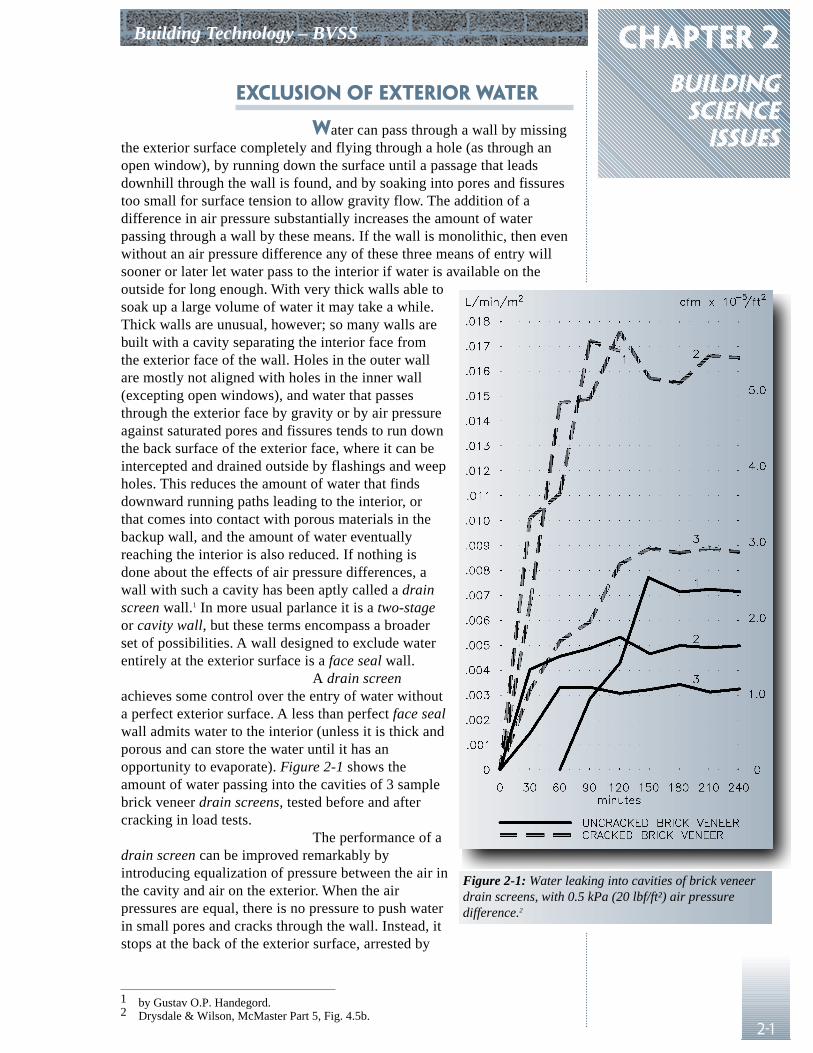
A drain screenachieves some control over the entry of water withouta perfect exterior surface. A less than perfect face sealwall admits water to the interior (unless it is thick andporous and can store the water until it has anopportunity to evaporate). Figure 2-1 shows theamount of water passing into the cavities of 3 samplebrick veneer drain screens, tested before and aftercracking in load tests.
The performance of adrain screen can be improved remarkably byintroducing equalization of pressure between the air inthe cavity and air on the exterior. When the airpressures are equal, there is no pressure to push waterin small pores and cracks through the wall. Instead, itstops at the back of the exterior surface, arrested by
1 by Gustav O.P. Handegord.2 Drysdale & Wilson, McMaster Part 5, Fig. 4.5b.
Figure 2-1: Water leaking into cavities of brick veneerdrain screens, with 0.5 kPa (20 lbf/ft²) air pressuredifference.2
BUILDING SCIENCE ISSUES Building Technology – BVSS
2-2
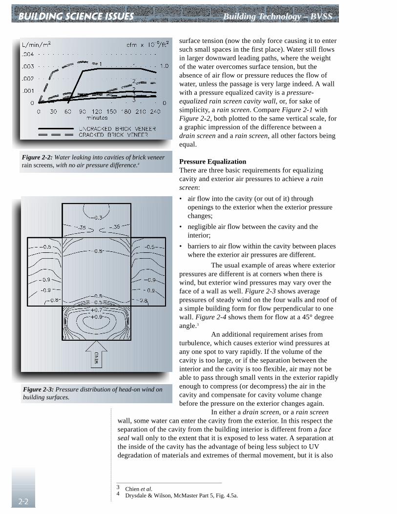
surface tension (now the only force causing it to entersuch small spaces in the first place). Water still flowsin larger downward leading paths, where the weightof the water overcomes surface tension, but theabsence of air flow or pressure reduces the flow ofwater, unless the passage is very large indeed. A wallwith a pressure equalized cavity is a pressure-equalized rain screen cavity wall, or, for sake ofsimplicity, a rain screen. Compare Figure 2-1 withFigure 2-2, both plotted to the same vertical scale, fora graphic impression of the difference between adrain screen and a rain screen, all other factors beingequal.
Pressure EqualizationThere are three basic requirements for equalizingcavity and exterior air pressures to achieve a rainscreen:
• air flow into the cavity (or out of it) throughopenings to the exterior when the exterior pressurechanges;
• negligible air flow between the cavity and theinterior;
• barriers to air flow within the cavity between placeswhere the exterior air pressures are different.
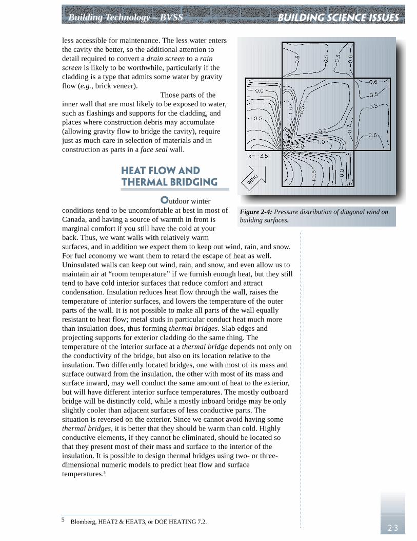
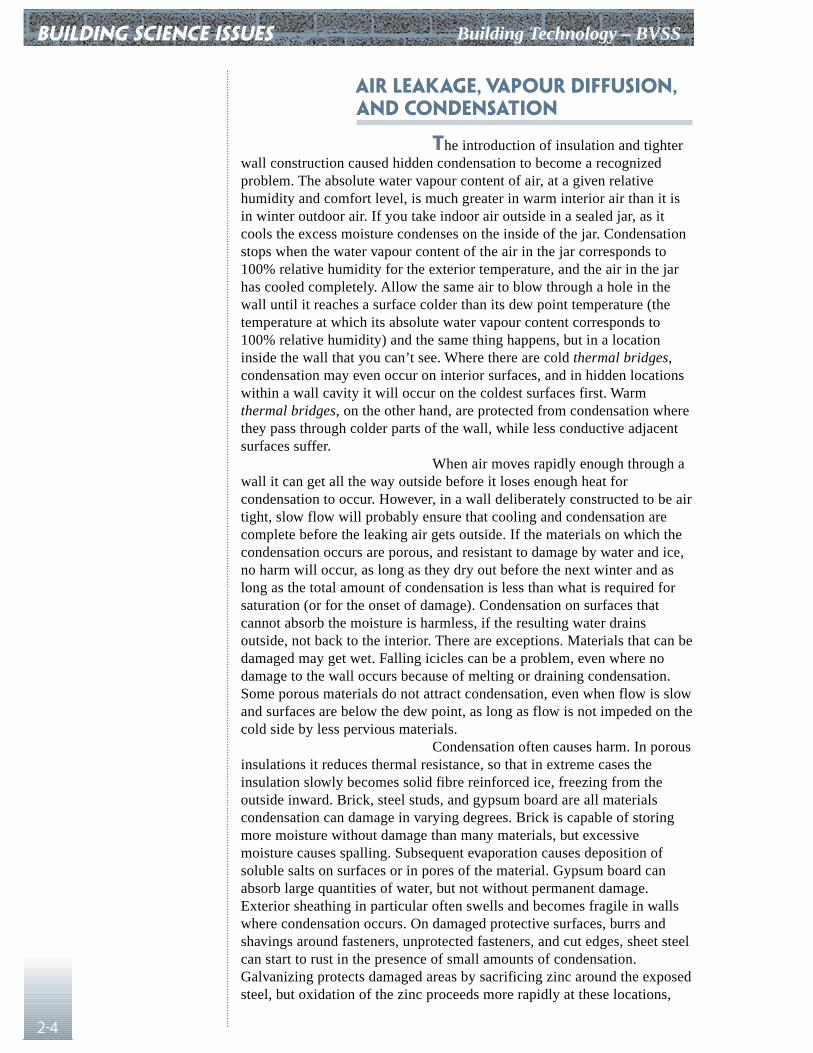
The usual example of areas where exteriorpressures are different is at corners when there iswind, but exterior wind pressures may vary over theface of a wall as well. Figure 2-3 shows averagepressures of steady wind on the four walls and roof ofa simple building form for flow perpendicular to onewall. Figure 2-4 shows them for flow at a 45° degreeangle.3
An additional requirement arises fromturbulence, which causes exterior wind pressures atany one spot to vary rapidly. If the volume of thecavity is too large, or if the separation between theinterior and the cavity is too flexible, air may not beable to pass through small vents in the exterior rapidlyenough to compress (or decompress) the air in thecavity and compensate for cavity volume changebefore the pressure on the exterior changes again.
In either a drain screen, or a rain screenwall, some water can enter the cavity from the exterior. In this respect theseparation of the cavity from the building interior is different from a faceseal wall only to the extent that it is exposed to less water. A separation atthe inside of the cavity has the advantage of being less subject to UVdegradation of materials and extremes of thermal movement, but it is also
Figure 2-2: Water leaking into cavities of brick veneerrain screens, with no air pressure difference.4
3 Chien et al.4 Drysdale & Wilson, McMaster Part 5, Fig. 4.5a.
Figure 2-3: Pressure distribution of head-on wind onbuilding surfaces.
Building Technology – BVSS
2-3
less accessible for maintenance. The less water entersthe cavity the better, so the additional attention todetail required to convert a drain screen to a rainscreen is likely to be worthwhile, particularly if thecladding is a type that admits some water by gravityflow (e.g., brick veneer).
Those parts of theinner wall that are most likely to be exposed to water,such as flashings and supports for the cladding, andplaces where construction debris may accumulate(allowing gravity flow to bridge the cavity), requirejust as much care in selection of materials and inconstruction as parts in a face seal wall.
Heat Flow and Thermal Bridging
Outdoor winterconditions tend to be uncomfortable at best in most ofCanada, and having a source of warmth in front ismarginal comfort if you still have the cold at yourback. Thus, we want walls with relatively warmsurfaces, and in addition we expect them to keep out wind, rain, and snow.For fuel economy we want them to retard the escape of heat as well.Uninsulated walls can keep out wind, rain, and snow, and even allow us tomaintain air at “room temperature” if we furnish enough heat, but they stilltend to have cold interior surfaces that reduce comfort and attractcondensation. Insulation reduces heat flow through the wall, raises thetemperature of interior surfaces, and lowers the temperature of the outerparts of the wall. It is not possible to make all parts of the wall equallyresistant to heat flow; metal studs in particular conduct heat much morethan insulation does, thus forming thermal bridges. Slab edges andprojecting supports for exterior cladding do the same thing. Thetemperature of the interior surface at a thermal bridge depends not only onthe conductivity of the bridge, but also on its location relative to theinsulation. Two differently located bridges, one with most of its mass andsurface outward from the insulation, the other with most of its mass andsurface inward, may well conduct the same amount of heat to the exterior,but will have different interior surface temperatures. The mostly outboardbridge will be distinctly cold, while a mostly inboard bridge may be onlyslightly cooler than adjacent surfaces of less conductive parts. Thesituation is reversed on the exterior. Since we cannot avoid having somethermal bridges, it is better that they should be warm than cold. Highlyconductive elements, if they cannot be eliminated, should be located sothat they present most of their mass and surface to the interior of theinsulation. It is possible to design thermal bridges using two- or three-dimensional numeric models to predict heat flow and surfacetemperatures.5
building science issues
5 Blomberg, HEAT2 & HEAT3, or DOE HEATING 7.2.
Figure 2-4: Pressure distribution of diagonal wind onbuilding surfaces.
BUILDING SCIENCE ISSUES Building Technology – BVSS
2-4
Air Leakage, Vapour Diffusion,and Condensation
The introduction of insulation and tighterwall construction caused hidden condensation to become a recognizedproblem. The absolute water vapour content of air, at a given relativehumidity and comfort level, is much greater in warm interior air than it isin winter outdoor air. If you take indoor air outside in a sealed jar, as itcools the excess moisture condenses on the inside of the jar. Condensationstops when the water vapour content of the air in the jar corresponds to100% relative humidity for the exterior temperature, and the air in the jarhas cooled completely. Allow the same air to blow through a hole in thewall until it reaches a surface colder than its dew point temperature (thetemperature at which its absolute water vapour content corresponds to100% relative humidity) and the same thing happens, but in a locationinside the wall that you can’t see. Where there are cold thermal bridges,condensation may even occur on interior surfaces, and in hidden locationswithin a wall cavity it will occur on the coldest surfaces first. Warmthermal bridges, on the other hand, are protected from condensation wherethey pass through colder parts of the wall, while less conductive adjacentsurfaces suffer.
When air moves rapidly enough through awall it can get all the way outside before it loses enough heat forcondensation to occur. However, in a wall deliberately constructed to be airtight, slow flow will probably ensure that cooling and condensation arecomplete before the leaking air gets outside. If the materials on which thecondensation occurs are porous, and resistant to damage by water and ice,no harm will occur, as long as they dry out before the next winter and aslong as the total amount of condensation is less than what is required forsaturation (or for the onset of damage). Condensation on surfaces thatcannot absorb the moisture is harmless, if the resulting water drainsoutside, not back to the interior. There are exceptions. Materials that can bedamaged may get wet. Falling icicles can be a problem, even where nodamage to the wall occurs because of melting or draining condensation.Some porous materials do not attract condensation, even when flow is slowand surfaces are below the dew point, as long as flow is not impeded on thecold side by less pervious materials.
Condensation often causes harm. In porousinsulations it reduces thermal resistance, so that in extreme cases theinsulation slowly becomes solid fibre reinforced ice, freezing from theoutside inward. Brick, steel studs, and gypsum board are all materialscondensation can damage in varying degrees. Brick is capable of storingmore moisture without damage than many materials, but excessivemoisture causes spalling. Subsequent evaporation causes deposition ofsoluble salts on surfaces or in pores of the material. Gypsum board canabsorb large quantities of water, but not without permanent damage.Exterior sheathing in particular often swells and becomes fragile in wallswhere condensation occurs. On damaged protective surfaces, burrs andshavings around fasteners, unprotected fasteners, and cut edges, sheet steelcan start to rust in the presence of small amounts of condensation.Galvanizing protects damaged areas by sacrificing zinc around the exposedsteel, but oxidation of the zinc proceeds more rapidly at these locations,
Building Technology – BVSS
2-5
and the protective action of galvanizing lasts only as long as there is stillzinc available. Although the relationship is difficult to quantify, thicknessof galvanizing and time duration of wetting combine to determine servicelife where corrosion occurs.
When condensation was first perceived asa problem, vapour diffusion through materials, driven by the difference inthe partial pressure of water vapour between interior and exterior, wasinitially identified as the culprit. This explanation, while very appealing,explains only a small portion of observed condensation. Vapour diffusiondoes occur, and causes condensation, but air leakage generally causes farmore and can better explain the observed amounts of condensation. Evenwalls constructed with care by people who are well aware of thepossibilities and strongly motivated to eliminate air leakage, are notsufficiently air tight that vapour diffusion can cause more condensationthan air leakage.6
Various levels of airtightness have beenrecommended. NRC has recommended 0.15 (0.03), 0.10 (0.02), and0.05 (0.01) L/s/m² (CFM/ft²) at 75 Pa (1.6 lbf/ft²) pressure difference, forlow, average, and high humidity occupancies.7 Many building sheathingand cladding materials are capable of meeting these requirements, ifcarefully fitted.8 However, measurements of actual buildings have producedrates varying from 0.5 (0.1) to 3.0 (0.6) L/s/m² (0.6 CFM/ft²) at the samepressure.9 Constant leakage of 1.0 L/s/m² (0.2 CFM/ft²) of air starting outat 22°C (72°F) and 30% relative humidity would carry 42 L/m² (1.1 USGals/ft²) of water into a wall over a three-month period. Such an amount isunlikely to accumulate since the pressure difference is usually less than75 Pa (1.6 lbf/ft²), pressure is not constant, and drying can occur duringwarmer weather. Still, it has been estimated that stack effect pressure forone story acting on a leakage area of 0.01% could result in accumulationand subsequent evaporation of 3 kg/m² (0.65 lbs/ft²) of moisture (a 3 mm(0.125 in.) layer of water) over a winter season, based on hourly weatherdata for Montreal.10
When wall materials are susceptible todamage from condensation, there are two ways to protect them: limit airleakage and vapour diffusion, or keep the materials above the dew point.Some materials can store moisture up to a point, without damage. In suchcases a third option is to limit accumulated condensation to the amount thatcan safely be stored and reliably evaporated under summer conditions. Toprevent any condensation whatever by limiting air leakage is very difficultin the lab, let alone on a construction site. The practical answer, for steelframing at least, is to keep the material warm. For gypsum board, somecondensation may be tolerable, perhaps as much as 5 or 10% by weightaccumulated over a full winter, a very small amount compared to themoisture that small amounts of air leakage can carry. A buildable airbarrier, capable of resisting the sum of all the air pressures applied to it,and tight enough to ensure proper cavity pressure equalization in a rainscreen, is difficult enough to build. Nevertheless, it will not be tight
building science issues
6 Drysdale and Kluge, McMaster Part 3.7 Building Science Insight ’86.8 Bumbaru et al, Air Permeance of Building Materials, and Brown and Poirier, Testing of
Air Barrier Systems for Wood Frame Walls.9 Shaw and Tamara, “Studies on Exterior Wall Air Tightness and Air Infiltration of Tall
Buildings.”10 TROW Inc. Criteria for The Air Leakage characteristics of Building Envelopes.
BUILDING SCIENCE ISSUES Building Technology – BVSS
2-6
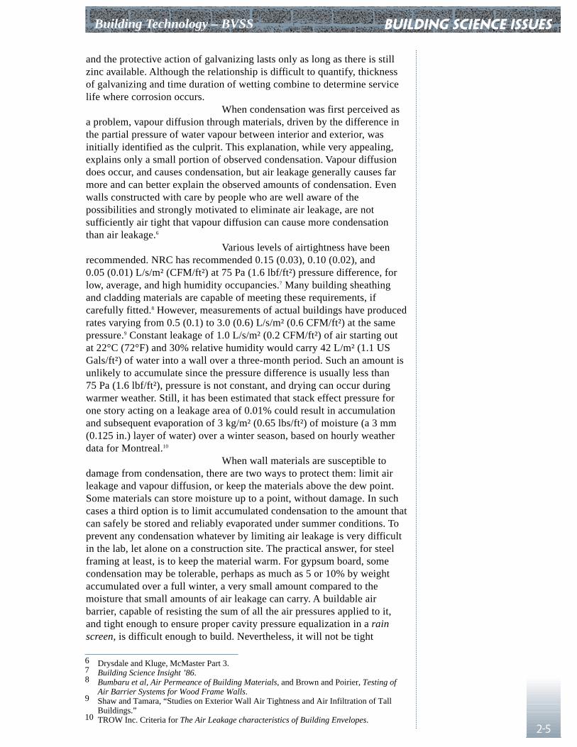
enough to prevent condensation on the back of exteriorgypsum board exposed to an uninsulated cavity behindveneer, or on steel studs that bridge the full thickness ofthe insulation. Figure 2-5 shows temperatures, and dewpoints for different interior humidities, at the backsurface of the gypsum sheathing in steel stud wallsinsulated in various ways. The peak in the centre of thegraph shows the effect of the metal stud as a warmthermal bridge; condensation is less likely on the studthan on the sheathing between studs, with the studsprotected by outboard insulation. Danger of condensationin the stud space is absent in only one instance, wherethere is 75 mm (3 in.) of cavity insulation and noinsulation in the stud space. With the stud spaceinsulated, 25 mm (1 in.) of cavity insulation suffices toprevent condensation on the studs, but not the sheathing,under the conditions tested.
Inaccuracy and Variation in Position
A last consideration that sometimes leadsto unexpected difficulties in service is the coordination ofdimensions and tolerances between components of thebuilding. For example, reasonable efforts to placeconcrete members in the intended location result invariations that are visually unacceptable when reflectedin finished exterior wall surfaces. Unless properlydesigned, taking permissible variations into account,steel stud wall framing and connections to the exterior
cladding may end up bridging the gap in ways that compromise theirserviceability. Details should still work when the components are at theirpermitted extremes of departure from intended position.
The whole question is more difficultbecause of the way the building industry generally treats tolerances.Statistical methods are rarely used, and little information is available aboutthe variances to be found in dimensions of actual buildings. Canadianstandards for concrete, steel, and masonry construction all refer totolerances, but only the concrete standard uses statistical concepts.
ConcreteCSA A23.1-94 governs tolerances for concrete construction. In anappendix it briefly discusses tolerances in relation to probability andprobability density distributions. It suggests that the Normal distributionprobably describes the distribution of errors in concrete dimensions inmost cases, and that tolerances should be specified as the intendeddimension plus or minus an amount sufficient to encompass a 90%confidence interval (an amount that would result in a 10% reject rate, onaverage, with the expected variance). In order to specify tolerances in stepsof equal difficulty of achievement, the following preferred ranges are
11 Drysdale and Suter, Exterior Wall Construction in High Rise Buildings.
Figure 2-5: Temperature at interior surface ofexterior sheathing, for exterior temperature of -20°C (-4°F), & interior temperature of 20°C (68°F),at horizontal distances of 0 to 300 mm (12 in.) fromstud centerline.11
A No insulation in stud space; 75 mm in cavityB Stud space insulated; 25 mm in cavity; 1.22 mm studC Like B, 0.91 mm studD Stud space insulated; no insulation in cavityE Stud space insulated; 25 mm rigid fiberglass on
interior face of studs
Building Technology – BVSS
2-7
suggested: ±3 (±0.12 in.), ±5 (±0.2 in.), ±8 (±0.3 in.), ±12 (±0.47 in.),±20 (±0.8 in.), ±30 (±1.2 in.), and ±50 mm (±2 in.).
A23.1 specifies the following tolerancesfor alignment of members with intended locations:
Dimension, m (ft.) Tolerance, mm (in.)0 - 2.4 (0 - 8) ±5 (0.2)2.4 - 4.8 (8 - 16) ±8 (0.3)4.8 - 9.6 (16 - 32) ±12 (0.47)9.6 - 14.4 (32 - 48) ±20 (0.8)14.4 - 19.2 (48 - 64) ±30 (1.2)19.2 - 57.6 (64 - 190) ±50 (2.0)above 57.6 (190) as specified
For thickness of columns and walls, andfor floor to floor offsets the tolerances are:
Dimension, m (ft.) Tolerance, mm (in.)0 - 0.3 (0 - 1) ±8 (0.3)0.3 - 1.0 (1 - 3.3) ±12 (0.47)1.0 - & up (3.3 & up) ±20 (0.8)
Vertical surfaces and arrises must be plumbto 1:400, up to ±40 mm (±1.6 in.) maximum. Sloped surfaces mustconform to slope within the same limits.
Ordinary floors are required to be level, inany 3 m (10 ft.), to within ±12 mm (±0.47 in.), but ±8 (±0.3 in.), ±5(±0. 2 in.), or ±3 mm (±0.12 in.) can be specified optionally. This is onetolerance that has been studied extensively. The cost of construction risesrapidly as improvements on ±12 mm (±0.47 in.) are introduced.
Structural SteelCAN/CSA S16.1-M89, Limit States Design of Steel Structures, definestolerances for steel building structures. Exterior columns must be plumb towithin 1:1000, to a cumulative total of up to -25 (-1 in.) or +50 mm(+2 in.) in the first 20 stories, with an additional allowance of 2 mm(0.08 in.) per story up to a maximum of -50 (-2 in.) or +75 mm (+3 in.) fortaller structures. Horizontal members are aligned in plan to within 1:1000,except that ±3 mm (±0.12 in.) is always acceptable, no matter how shortthe member, and ±6 mm (±0.24 in.) is the maximum in any case.Horizontal members are at the correct elevation, if within ±10 mm(±0.4 in.), and must slope no more than 1:500. When connections areadjustable, members must be level to within 1:1000. Abutting ends arerequired to align within ±3 mm (±0.12 in.), or, if adjustable, within±2 mm (±0.08 in.).
building science issues
BUILDING SCIENCE ISSUES Building Technology – BVSS
2-8
MasonryCSA A371-94 Masonry Construction for Buildings restricts errors inposition. It requires masonry construction to meet the following tolerances,unless otherwise specified. Previous editions of this standard suggestedtolerances, but they were not mandatory.
Vertical Alignment:±20 mm (±0.8 in.) in surface of wall±13 mm (±0.5 in.) in alignment of head joints
Lateral Alignment:±13 mm (±0.5 in.) vertical members
Level Alignment:±13 mm (±0.5 in.) for bed joints and exposed tops of walls±25 mm (±1 in.) not exposed±13 mm (±0.5 in.) top of wall used as a bearing surface±20 mm (±0.8 in.) top of wall, not bearing
Cross-sectional Dimensions:+13 mm (±0.5 in.), -6 mm (-0.24 in.)
Joint thickness:±3 mm (±0.12 in.) for 10 mm (0.4 in.) nominal head and bed joints6 - 20 mm (0.24 - 0.8 in.) for bed joint of starting course
Relative Alignment:±6 mm (±0.24 in.) over 3000 mm (120 in.) change in positionrelative to reference plane
Field ExperienceAre tolerances specified in applicable codes and specifications actuallyachieved in the field? Experience suggests that they are exceeded relativelyfrequently.12 The specified tolerances are difficult enough to deal with; onecase has been observed where the actual wall cavity dimension varied from0 (0 in.) to 75 mm (3 in.), as opposed to 50 mm (2 in.) shown on thedrawings.13
Keller reported cavities as much as 17 mm(0.7 in.) smaller and 20 mm (0.8 in.) larger than the dimension detailed.The range from smallest to largest cavity dimension on a single buildingaveraged 19 mm (0.75 in.). The range was never less than 10 mm (0.4 in.)(seen on two buildings), and on the worst building it was 37 mm (1.5 in.).14
12 Experience includes cases of tolerance for floor flatness exceeded by a factor of 10, anda column (in the worst case out of 100 measured) out of plumb by 75 mm (3 in.) in 2440 mm (100 in.).
13 J. Vlooswyk, Building Envelope Engineering.14 Keller, H., Field Investigation of Brick Veneer/Steel Stud Wall Systems.
chapter 3cmhc
researchfindings
3-1
User Survey and Field Observations1
In 1986 Keller examined eight buildings infour cities from St. John’s to Calgary, and sent out a questionnaire topeople he expected were involved in BVSS construction. One hundred andeleven architects and engineers, 23 masonry contractors, 16 sheet steelframing contractors, and 21 building officials responded; 76% had someexperience with BVSS. Most were from southern Ontario or Quebec.Collectively, he estimated that the response involved experience of somesort with over 1000 buildings, 66% of them four stories or less in height,52% framed in steel, and 44% in reinforced concrete.
The architect usually designed the steelstud framing (65% of cases) mainly relying on manufacturer’s literature forguidance, and to a lesser extent on CSA standards, the NBC, CMHCreports, and similar sources. Engineers acting as prime consultant (28%)relied on the same sources. Only 8% of all designers relied on the opinionof a structural engineer.
Shop drawings were required: never(33%); seldom (28%); sometimes (16%); often (7%); and, in some cases,always (16%). Framing was mechanically fastened more often than welded(74% vs. 6%). 95% were fabricated on site. A sliding top connection wasprovided 68% of the time. Explosive actuated fasteners were used forattachment to the structure 70% of the time. Stud spaces were more ofteninsulated than not (64%). If rigid insulation was used, it was usually, butnot always on the outside of the framing. The vapour barrier was almostalways on the inside face of the framing (89%) and consisted ofpolyethylene film (84%).
Most of the designers had encounteredproblems in the field, most commonly air infiltration; 83% felt that notenough information was available, and that design fees do not allow forproper design. Contractors felt that construction documents provided toolittle guidance, and that responsibility for design, especially of details andconnections, was left to them too often. BVSS systems had been in use inthe areas sampled for an average of about eight years.
In the field study that followed the survey,Keller made a general visual examination of the veneer, did thermographicsurveys, and made visual inspections of the stud space and the cavitybehind the veneer through openings made from the interior.2 Visualexamination and thermographic survey from the exterior revealed nothingthat might not have been seen in any masonry veneer building. Where therewere problems with the framing, ties, or with air leakage, these methodsdid not reveal the locations.
Building Technology – BVSS
1 Keller, Brick Veneer/Steel Stud Wall Design and Construction Practices in Canada: Results of a 1986 Survey, and Keller, Trestain, and Maurenbrecher, The Durability of Steel Components in Brick Veneer/Steel Stud Wall Systems.
2 Keller, Field Investigation of Brick Veneer/Steel Stud Wall Systems.
CMHC RESEARCH FINDINGS Building Technology – BVSS
3-2
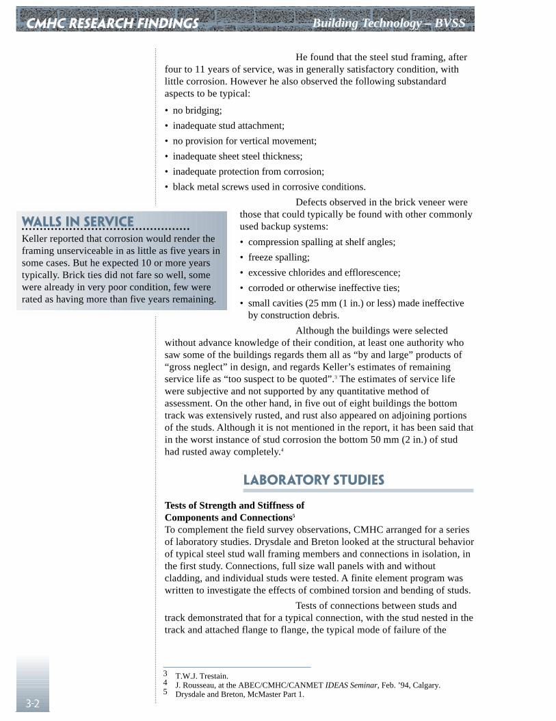
He found that the steel stud framing, afterfour to 11 years of service, was in generally satisfactory condition, withlittle corrosion. However he also observed the following substandardaspects to be typical:
• no bridging;
• inadequate stud attachment;
• no provision for vertical movement;
• inadequate sheet steel thickness;
• inadequate protection from corrosion;
• black metal screws used in corrosive conditions.
Defects observed in the brick veneer werethose that could typically be found with other commonlyused backup systems:
• compression spalling at shelf angles;
• freeze spalling;
• excessive chlorides and efflorescence;
• corroded or otherwise ineffective ties;
• small cavities (25 mm (1 in.) or less) made ineffectiveby construction debris.
Although the buildings were selectedwithout advance knowledge of their condition, at least one authority whosaw some of the buildings regards them all as “by and large” products of“gross neglect” in design, and regards Keller’s estimates of remainingservice life as “too suspect to be quoted”.3 The estimates of service lifewere subjective and not supported by any quantitative method ofassessment. On the other hand, in five out of eight buildings the bottomtrack was extensively rusted, and rust also appeared on adjoining portionsof the studs. Although it is not mentioned in the report, it has been said thatin the worst instance of stud corrosion the bottom 50 mm (2 in.) of studhad rusted away completely.4
Laboratory Studies
Tests of Strength and Stiffness of Components and Connections5
To complement the field survey observations, CMHC arranged for a seriesof laboratory studies. Drysdale and Breton looked at the structural behaviorof typical steel stud wall framing members and connections in isolation, inthe first study. Connections, full size wall panels with and withoutcladding, and individual studs were tested. A finite element program waswritten to investigate the effects of combined torsion and bending of studs.
Tests of connections between studs andtrack demonstrated that for a typical connection, with the stud nested in thetrack and attached flange to flange, the typical mode of failure of the
Walls in serviceKeller reported that corrosion would render theframing unserviceable in as little as five years insome cases. But he expected 10 or more yearstypically. Brick ties did not fare so well, somewere already in very poor condition, few wererated as having more than five years remaining.
3 T.W.J. Trestain.4 J. Rousseau, at the ABEC/CMHC/CANMET IDEAS Seminar, Feb. ’94, Calgary.5 Drysdale and Breton, McMaster Part 1.

Building Technology – BVSS
3-3
connection is crippling of the stud web. Experimental loads were safely inexcess of the safe loads determined by current design procedures. Thedeformations resulting in failure were typically confined to the ends ofstuds, within a distance along the length less than the stud depth.
Most significant for design of other partsof a wall, connections of this type exhibited displacements before failurethat were relatively large, compared to the displacement at mid-span of astud designed for L/720 deflection. The rate of displacement variedconsiderably with the method of connecting the flanges, and how muchgap there was between the stud end and the web of the track.
In addition to screws through the flanges,several other arrangements were tested:
• box track (stud blocked to prevent twisting, but not fastened);
• nested track (stud flanges screwed to inner track withminimum gap at end, 12 mm (0.5 in.) between thewebs of the two tracks, outer track not fastened toinner);
• clip angle, securing the stud web directly to thesupport, with slotted fastener holes to accommodate12 mm (0.5 in.) of movement;
• flexible clip, secured to stud web, and to the support,also allowing 12 mm (0.5 in.) of movement.
Connections thatattached the web of the stud directly to the supportwith a sliding clip angle, or a flexible clip, tended to bevery stiff, allowing relatively little displacement beforefailure. They also tended to fail suddenly by shearingfasteners or pulling them out of the support. Loads atfailure were safely in excess of design loads for theseconnections as well.
CMHC RESEARCH FINDINGS
Recommendations• Verify that the design accounts for secondary
torsional effects and web crippling.6
• Use metal bridging, spaced at 1220 mm (48 in.)maximum centres. For heavier studs, usethrough-the-cutout bridging fastened to studswith clip angles.7
• Make bridging continuous, and provide periodicanchorage.
• If ties are attached to stud flanges, take resultingreduction in stud capacity into account. Do notlocate ties where there are web cutouts.
• If cutouts are located where there is no bridging,allow for resulting reduction in stud capacity.Best location for unbraced cutouts is between300 (12 in.) and 400 mm (16 in.) from eitherend of stud.
• Consider the effect of displacement at supportson cladding and finish materials, in addition toevaluating ultimate capacity of the stud tostructure connection.
• When cladding is used to provide bracing,specifically design the cladding and method offastening for the purpose, and use more durablematerial than gypsum board.8
6 If design tables are used, verify that these effects were considered.7 Notched channel bridging, fastened to both faces of the studs, was also tested.
Other research reportedly indicates that flat strap bridging can be as effective.Unbraced specimens performed poorly compared to those with any type of bridging.
8 If steel bridging is attached to studs, interior gypsum board may reliably prevent translation of the bridging in the plane of the wall.
CMHC RESEARCH FINDINGS Building Technology – BVSS
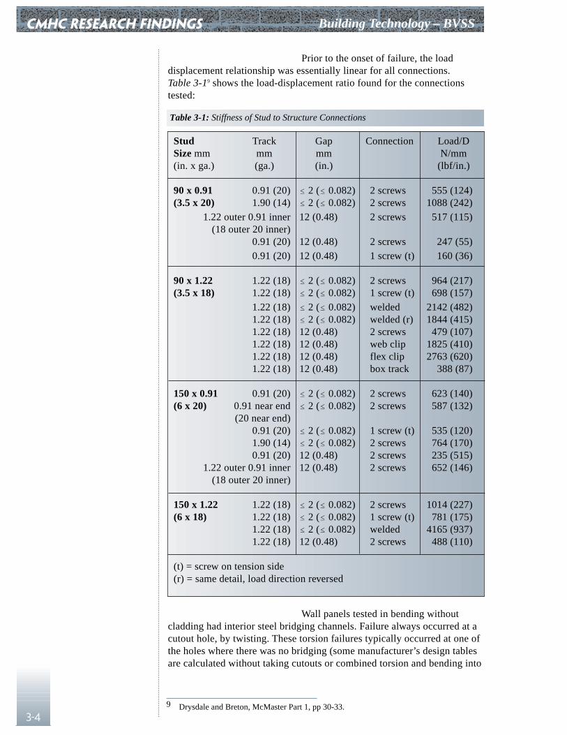
3-4
Prior to the onset of failure, the loaddisplacement relationship was essentially linear for all connections.Table 3-19 shows the load-displacement ratio found for the connectionstested:
Wall panels tested in bending withoutcladding had interior steel bridging channels. Failure always occurred at acutout hole, by twisting. These torsion failures typically occurred at one ofthe holes where there was no bridging (some manufacturer’s design tablesare calculated without taking cutouts or combined torsion and bending into
Stud Track Gap Connection Load/DSize mm mm mm N/mm(in. x ga.) (ga.) (in.) (lbf/in.)
90 x 0.91 0.91 (20) � 2 (� 0.082) 2 screws 555 (124)(3.5 x 20) 1.90 (14) � 2 (� 0.082) 2 screws 1088 (242)
1.22 outer 0.91 inner 12 (0.48) 2 screws 517 (115)(18 outer 20 inner)
0.91 (20) 12 (0.48) 2 screws 247 (55)0.91 (20) 12 (0.48) 1 screw (t) 160 (36)
90 x 1.22 1.22 (18) � 2 (� 0.082) 2 screws 964 (217)(3.5 x 18) 1.22 (18) � 2 (� 0.082) 1 screw (t) 698 (157)
1.22 (18) � 2 (� 0.082) welded 2142 (482)1.22 (18) � 2 (� 0.082) welded (r) 1844 (415)1.22 (18) 12 (0.48) 2 screws 479 (107)1.22 (18) 12 (0.48) web clip 1825 (410)1.22 (18) 12 (0.48) flex clip 2763 (620)1.22 (18) 12 (0.48) box track 388 (87)
150 x 0.91 0.91 (20) � 2 (� 0.082) 2 screws 623 (140)(6 x 20) 0.91 near end � 2 (� 0.082) 2 screws 587 (132)
(20 near end)0.91 (20) � 2 (� 0.082) 1 screw (t) 535 (120)1.90 (14) � 2 (� 0.082) 2 screws 764 (170)0.91 (20) 12 (0.48) 2 screws 235 (515)
1.22 outer 0.91 inner 12 (0.48) 2 screws 652 (146)(18 outer 20 inner)
150 x 1.22 1.22 (18) � 2 (� 0.082) 2 screws 1014 (227)(6 x 18) 1.22 (18) � 2 (� 0.082) 1 screw (t) 781 (175)
1.22 (18) � 2 (� 0.082) welded 4165 (937)1.22 (18) 12 (0.48) 2 screws 488 (110)
(t) = screw on tension side (r) = same detail, load direction reversed
9 Drysdale and Breton, McMaster Part 1, pp 30-33.
Table 3-1: Stiffness of Stud to Structure Connections
Building Technology – BVSS
3-5
account). The studs used were commercially available studs with cutouts atabout 650 mm (26 in.) centres. Spans were tested with one row of metalbridging at mid-span in some cases, and with 2 rows of bridging. Theultimate load was strongly influenced by the attachment of the bridging tothe studs. Clip angles fastened with screws were most effective with4 screws, 2 into the bridging channel, and 2 into the stud web. Welded clipangles were equally effective. The ultimate moments in bending weretypically less than allowable moments calculated using simple beam theoryand the section modulus of the perforated section (at a cutout). Wallsbraced with cladding were also tested. Conditions included drywall withstandard fastener spacing and reduced spacing, and wetted gypsumsheathing. The ratio of actual maximum moment sustained before failure toyield moment predicted by simple bending theory from the perforatedsection properties ranged from 0.57 to 1.03 over the full range of testconditions. It ranged from 0.81 to 0.98 for unclad specimens with metalbracing.10
The report also explores theoretical modelsfor combined bending and torsion, and for combined action of brick veneerwith steel stud backup.
Tests of Water Permeability of Cracked Masonry Veneer11
A preliminary series of leakage tests with small masonry specimensevaluated the effect of cracking isolated from other variables. The resultswere scattered and in any event, not very useful in predicting wallperformance. They did indicate a degree of self-healing. The rate ofleakage through cracked masonry decreases with time, with constantpressure.
Small Scale Tests with Temperature, Air Pressure,and Vapour Pressure Differentials12
Five BVSS wall specimens were tested. The air pressures used wereintended not to test the structural adequacy of the walls (since the sampleswere only 830 (33 in.) x 1240 mm (50 in.)), but to provide typical drivingforces for air leakage and rain penetration. They found that seeminglysmall construction flaws can result in service problems in some designs,but that other designs were relatively defect tolerant.
Walls tested include the following:
Wall 1
• taped and painted 12.7 mm (0.5 in.) gypsum board;
• 0.15 mm (6 mil) polyethylene vapour barrier;
• 92 mm (3.7 in.) studs and track of 0.91 mm (20 ga.) steel (studs at 406 mm(16 in.) centres);
• RSI 2.1 (R12) glass fibre batt in stud space;
• 12.7 mm (0.5 in.) exterior gypsum sheathing;
• 25 mm (1 in.) vented cavity;
CMHC RESEARCH FINDINGS
10 Drysdale and Breton, McMaster Part 1, Tables 4.3, 4.5, & 4.6.11 Drysdale, Kluge and Roscoe, McMaster Part 2.12 Drysdale and Klauge, McMaster Part 3.
CMHC RESEARCH FINDINGS Building Technology – BVSS
3-6
• brick ties;
• brick veneer.
Wall 2
• unfinished 12.7 mm (0.5 in.) gypsum board;
• 0.15 mm (6 mil) polyethylene vapour barrier;
• 92 mm (3.7 in.) studs and track of 0.91 mm (0.04 in.) steel (studs at406 mm (16 in.) centres);
• RSI 2.1 (R12) glass fibre batt in stud space;
• RSI 0.88 (R5), 25 mm (1 in.) polystyrene sheathing;
• 25 mm (1 in.) vented cavity;
• brick ties;
• brick veneer.
Wall 3
• taped and painted 12.7 mm (0.5 in.) gypsum board;
• 25 mm (1 in.) steel hat channels;
• 0.15 mm (6 mil) polyethylene vapour barrier;
• 12.7 mm (0.5 in.) gypsum sheathing, joints caulked;
• back to back 1.21 mm (0.05 in.) thickness steel studs;
• RSI 2.2 (R12.5) glass fibre insulation;
• 38 mm (1.5 in.) polystyrene caps on stud flanges (rebated 13 mm (0.5 in.)deep to fit over studs and retain fiberglass insulation);
• 50 mm (2 in.) cavity (from face of studs);
• brick ties;
• brick veneer.Corrosion of drywall screws occured in
tests with no exterior insulation after relatively short exposures. Thediscussion observed that conventional drywall screws have a black oiledfinish without corrosion resistant plating. During installation, themagnetized bit of the screw gun magnetizes the screws, so that fineparticles cut from the stud as the screw is driven remain on the screw. Withthe cuttings, the minimally protected screw, and burrs from the stud atpoint of penetration, there is considerable scope for corrosion in moistconditions.
The second wall, with 25 mm (1 in.) ofexterior polystyrene insulation, was tested with a deliberate imperfectionequivalent to a 0.3 mm (0.01 in.) x 12 mm (0.48 in.) crack for every squaremeter. Interior relative humidity was 35 - 40% with 21°C (70°F) interiortemperature and -17°C (1°F) exterior temperature. A pressure difference of75 Pa (1.6 lbf/ft²) resulted in leakage of 0.011 L/s/m² (0.002 CFM/ft²).After 13 days there was no sign of any moisture having accumulatedanywhere in the wall. Under more severe conditions with 50 - 55% interior relative humidity, condensation occurred on the insidesurface of the polystyrene insulation, but not on any of the steelcomponents.
Building Technology – BVSS
3-7
Drysdale and Kluge observed that:
• even small openings in the air barrier can allowsignificant air leakage;
• the intended air barrier is not necessarily the onlyelement in the wall that resists air flow;
• unpainted gypsum board is not airtight, but two coatsof latex paint are enough to serve as a vapour barrier;
• even with great care taken in the lab, unexpected airleaks occur; they should be anticipated onconstruction sites and means of detection and repairshould be provided;
• an outboard air barrier may also function as a vapourbarrier, and trap condensation in between two vapourbarriers;
• air leakage paths around insulation can short circuitthe insulation and reduce its effectiveness;
• the steel framing of BVSS walls can be kept above thedew point temperature only by insulation in thecavity;
• the effects of studs as thermal bridges extend50 (2 in.) to 100 mm (4 in.) to either side of the stud;
• large steel fasteners used to fasten rigid insulationfrom the exterior “affect the local thermal profile byless than 5%”;13
• any air leakage, however small, can causecondensation somewhere within the wall; even leakage as low as0.03 L/s/m² (0.006 CFM/ft²) results in significant accumulations;
• moisture accumulation due to vapour diffusion is so small it cannot bemeasured;
• unplated screws, burrs, and chips will quickly begin to rust if they arebelow the dew point temperature.
They concluded that air barriers should beincluded in all wall designs, but that they should not be assumed to beperfect. It should be taken for granted that condensation will occursomewhere; the important question is where will it occur, and will it causeany damage? If it will occur in the stud space or on the framing, haveadequately moisture resistant materials been used? Air barriers should, ifpossible, be located where they can be inspected and repaired. Unintendedair or vapour barriers should be avoided, to prevent accumulation ofcondensation or other moisture that cannot escape.
Tests of Brick Ties With Steel Studs14
This study tested 12 commonly used types of masonry tie with steel studsin various configurations to determine both stiffness and ultimate loadcarrying capacity in both tension and compression. Many ties were found
CMHC RESEARCH FINDINGS
Recommendations• Keep studs above the dew point temperature of
the interior air, since small amounts of airleakage are difficult to prevent, yet can transportenough moisture to cause significant corrosion.
• Polystyrene sheathing significantly reduces thepotential for condensation in an insulated studspace, but does not eliminate it. Condensation iseliminated on the framing, but may still occuron the back and in the joints of the sheathing.
• The best way to avoid condensation is toeliminate all insulation from the stud space andinsulate only the cavity. From theory, with adesign temperature of minus 30°C (-20°F) andinterior relative humidity of 30%, 76 mm (3 in.)of Type 4 polystyrene with no insulation in thestud space is required to eliminate allcondensation. If there is insulation in the studspace, condensation is eliminated on theframing, but not on the back of the exteriorsheathing. It may damage gypsum sheathing,lead to wetting and sagging of the stud spaceinsulation, and increase the frequency and timeof wetness of the bottom track.
13 The actual temperature difference was not reported.McMaster Part 3, page 151.
14 Drysdale and Wilson, McMaster Part 4.
CMHC RESEARCH FINDINGS Building Technology – BVSS
3-8
wanting, particularly at the extremes of adjustment. Point loads applied byties to studs were also found to be capable of compromising theperformance of the studs, in some cases. The object of the tests was to findties meeting the following criteria:
• strength and stiffness adequate for structural requirements;
• robustness and durability to survive job site conditions;
• tolerance for, or limitations on, adjustment and misalignment as needed toensure structural performance;
• adequate corrosion protection, including attachments;
• compatibility with sheathing, air barrier, insulation and other adjoiningmaterial and installation procedures;
• cost and convenience of use, including ease of inspection.
A wide range of previous work wasreviewed at the outset, including research, industry technicalrecommendations, and standards. Except for the corrugated strip tie, theties selected appeared to have some merit.
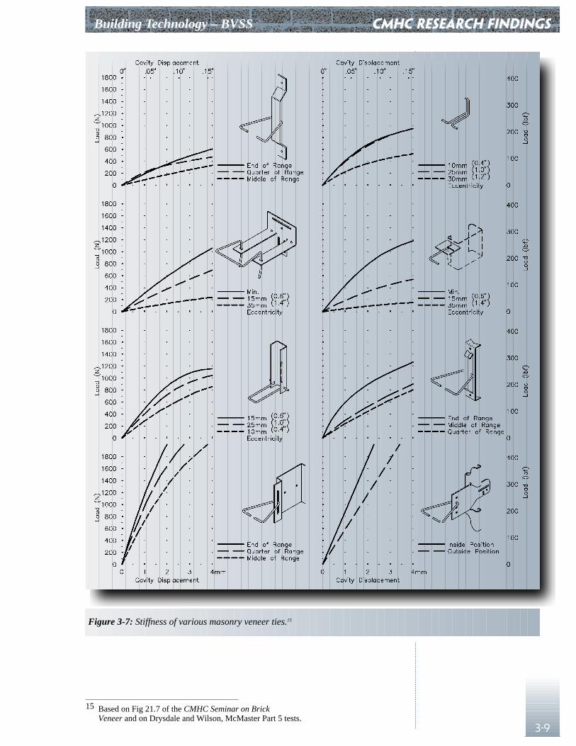
A displacement of 4 mm (0.16 in.) betweenthe centerline of the stud and the back of the veneer was used as a limitstate criterion. Ties were attached to 0.91 mm (20 ga.) studs, 1.22 mm(18 ga.) studs, and rigid supports. The effect of positioning ties at differentlocations on the stud flange was also investigated. Most of the tests weredone with 0.91 mm (20 ga.) studs, and ties attached either to the web, or15 mm (0.6 in.) from the web on the flange, depending on type of tie.Sheathing was gypsum board, for types of tie normally attached throughthe sheathing. Tension tests were done on several types of screw fastenersused for tie to flange connections. Adjustable ties were tested at differentpositions, including the least favorable.
Ties that permit adjustment ranged widelyin the effect various positions had on tie capacity and stiffness; in the worstcase the load at 1.2 mm (0.05 in.) displacement was 10.5% of that whichthe same tie could carry in the most favorable position. Loads required toproduce 1.2 mm (0.05 in.) displacement varied from 53 (12 lbf) to 1277N(290 lbf).
Ties that attach to the flange of the studwere very sensitive to their position on the flange relative to the web, andto crushing of the gypsum sheathing where they were bearing on it. Tiesthat adjust by sliding a wire into a hole were very weak at the extremeposition. Ties that attach with screws loaded in tension when tie load isnegative were found to pry against the screws, and to be susceptible tofatigue with repeated load reversal.
The best ties were those that attach directlyto the web of the stud, using fasteners loaded in shear.
Building Technology – BVSS
3-9
CMHC RESEARCH FINDINGS
Figure 3-7: Stiffness of various masonry veneer ties.15
15 Based on Fig 21.7 of the CMHC Seminar on BrickVeneer and on Drysdale and Wilson, McMaster Part 5 tests.
CMHC RESEARCH FINDINGS Building Technology – BVSS
3-10
Full Scale Tests with Simulation of Wind and Rain16
Drysdale and Wilson tested five, full scale (2.75 (9 ft.) x5.2 m (17 ft.)) brick veneer wall specimens, using a newtest apparatus capable of simulating wind and rainsimultaneously. Four of the specimens were BVSS. Theylooked at structural performance under varying loads,and at rain penetration performance of walls includingboth drain screens and rain screens. They observed thateven carefully constructed drain screens are likely toexperience excessive rain penetration under commonlyoccurring conditions, and that cracking of brick veneeroccurs at loads somewhat more than the design loadbased on an L/720 deflection criterion for the studs. Insummarizing they made the following “Good PracticeRecommendations,” in addition to several moretraditional recommendations:
• provide a 50 mm (2 in.) minimum clear air space in thecavity;
• divide the cavity into compartments; keep cutout holesin studs away from mid-height;17
• fasten bridging to studs with clip angles and four screwsat each connection;18
• splice and fasten joints in bridging;
• screw studs to legs of track on both sides;
• provide at least double studs at openings;
• use ties with minimal free play and flexibility;
• place line of action of tie force as close to stud web aspossible.
The steel stud walls tested had 25 mm(1 in.) cavities and all but one used the interior drywall asthe air barrier (one wall had a peel and stick membraneapplied to exterior sheathing). There was no insulation.Various ties were used, selected for average performancefrom a previous test program. All walls provided forvertical movement of the supporting structure, typicallywith a nested top track. One wall was unusual. It hadstuds placed back to back at twice the usual spacing, andhung from the top with provision for vertical deflectionat the bottom. Except for this wall, all walls hadmechanically fastened lateral bracing and studs spaced at406 mm (16 in.) centres.
Full Scale test findings• Cavity pressurization reduces rain penetration
into the cavity substantially, but cavitycompartmentation is necessary to achieve it. Avented cavity is not enough.
• Conventional weep holes and spacings aresufficient for cavity pressurization, if the cavityis compartmented.
• Most water penetration through brick veneeroccurs in the head joints. They should be filledwhen the masonry is laid.
• Unsealed joints at the top of the veneer can leadto very large volumes of rain penetration;unprotected vents at the top of the wall alsoallow substantial penetration.
• Cracked veneer has little impact on rainpenetration, if the cavity is pressurized.
• Veneer ties are not loaded uniformly; very largeforces occur at the top ties prior to cracking,and at ties adjacent to cracks after cracking.
• The critical load condition for veneer and forties occurs when the load is being carried by theveneer, i.e. when the cavity is not pressurized,and before veneer cracking.
• Prior to cracking, the stiffness of the veneerprevents the studs from bending; the studs donot carry a uniformly distributed load.
• The air pressure required to cause cracking isdetermined more by the strength of the masonryalone than any other factor.
• Tight packing of the top joint provides a topsupport condition for the veneer (even sealantwill provide restraint) which transfers part ofthe reaction at the top from the studs to the shelfangle.19
• Supporting the end studs of the backup wallalong their length introduces two way bendingbehavior in the veneer, that reducesdisplacement of the wall and reduces secondarycracking.20
16 Drysdale and Wilson, McMaster Part 5.17 This is good advice in view of the location of maximum bending moment, but
not practical for a 2400 mm (95 in.) high wall with one row of internal bridging. It is acceptable to include cutouts at mid height when the effect has been taken into account in the manufacturer’s load tables.
18 There is nothing wrong with bridging on the faces of the studs; but the studs still have to be restrained from rotating in unison. Drysdale was unable to do this reliably in the McMaster Part 1 test setup.
19 This may change the load at first crack and the pattern of cracking of the veneer.20 In practice, this effect varies with aspect ratio, a constant during the tests.
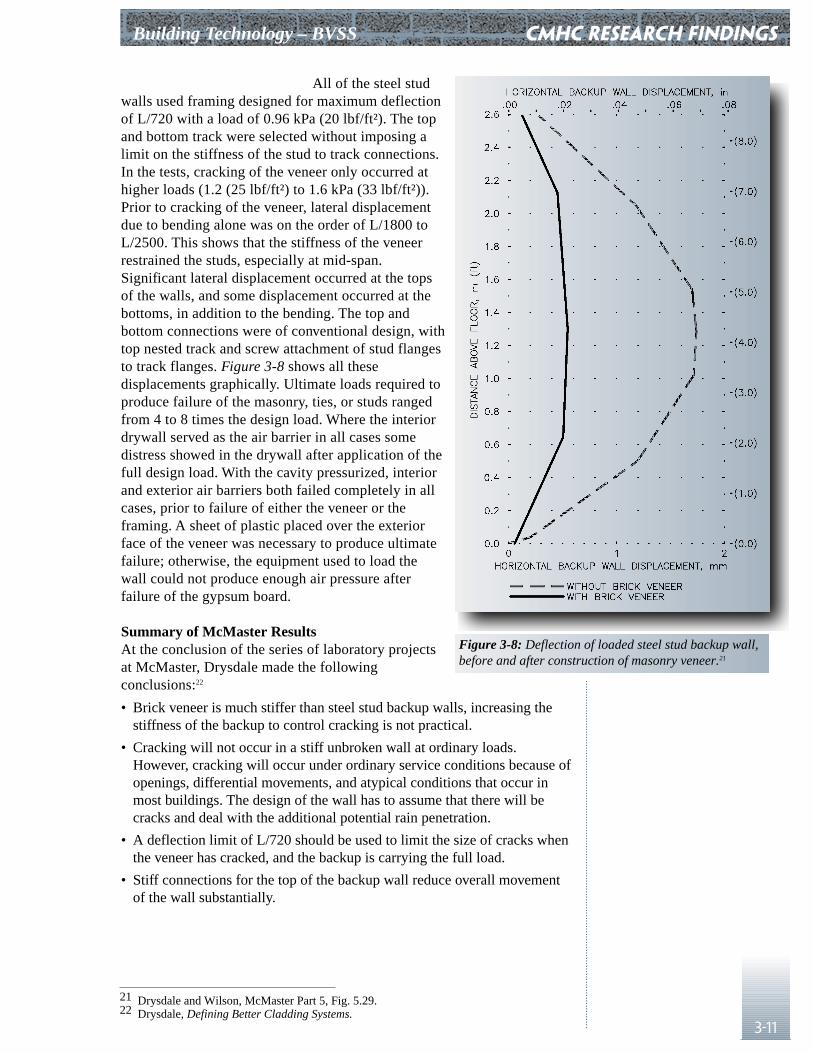
Building Technology – BVSS
3-11
All of the steel studwalls used framing designed for maximum deflectionof L/720 with a load of 0.96 kPa (20 lbf/ft²). The topand bottom track were selected without imposing alimit on the stiffness of the stud to track connections.In the tests, cracking of the veneer only occurred athigher loads (1.2 (25 lbf/ft²) to 1.6 kPa (33 lbf/ft²)).Prior to cracking of the veneer, lateral displacementdue to bending alone was on the order of L/1800 toL/2500. This shows that the stiffness of the veneerrestrained the studs, especially at mid-span.Significant lateral displacement occurred at the topsof the walls, and some displacement occurred at thebottoms, in addition to the bending. The top andbottom connections were of conventional design, withtop nested track and screw attachment of stud flangesto track flanges. Figure 3-8 shows all thesedisplacements graphically. Ultimate loads required toproduce failure of the masonry, ties, or studs rangedfrom 4 to 8 times the design load. Where the interiordrywall served as the air barrier in all cases somedistress showed in the drywall after application of thefull design load. With the cavity pressurized, interiorand exterior air barriers both failed completely in allcases, prior to failure of either the veneer or theframing. A sheet of plastic placed over the exteriorface of the veneer was necessary to produce ultimatefailure; otherwise, the equipment used to load thewall could not produce enough air pressure afterfailure of the gypsum board.
Summary of McMaster ResultsAt the conclusion of the series of laboratory projectsat McMaster, Drysdale made the followingconclusions:22
• Brick veneer is much stiffer than steel stud backup walls, increasing thestiffness of the backup to control cracking is not practical.
• Cracking will not occur in a stiff unbroken wall at ordinary loads.However, cracking will occur under ordinary service conditions because ofopenings, differential movements, and atypical conditions that occur inmost buildings. The design of the wall has to assume that there will becracks and deal with the additional potential rain penetration.
• A deflection limit of L/720 should be used to limit the size of cracks whenthe veneer has cracked, and the backup is carrying the full load.
• Stiff connections for the top of the backup wall reduce overall movementof the wall substantially.
CMHC RESEARCH FINDINGS
Figure 3-8: Deflection of loaded steel stud backup wall,before and after construction of masonry veneer.21
21 Drysdale and Wilson, McMaster Part 5, Fig. 5.29.22 Drysdale, Defining Better Cladding Systems.
CMHC RESEARCH FINDINGS Building Technology – BVSS
3-12
• Walls with large openings crack at much lower loads. Independent supportfor large windows and doors should be considered. Thin strips of veneeradjoining openings are susceptible to cracking.
• Double studs at openings have little effect on cracking load, but do limitsubsequent deflection. If large openings do not have independent supportsit may be necessary to double several studs in addition to thoseimmediately adjacent to the opening.
• A soft joint at the top can significantly restrain the veneer, and effectivelyincrease its vertical span, reducing cracking loads.
• A wall works better structurally when most of the pressure difference actson the backup, rather than the face of the wall.
• Before cracking, the top tie transfers approximately half of the load fromthe veneer to the backup. After cracking, a tie near mid-height may carrythe same load.
• More flexible ties can result in higher cracking loads and lower maximumtie forces. To avoid undue movement and distress in sealants and adjoiningwork, a load of 450 N (100 lbf) should result in a 2 mm (0.08 in.)maximum movement, including mechanical play and backup distortion.
• Condensation of moisture from air moving through walls is a seriousconcern.
CMHC Research Project Testing of Air Barriers Construction Details23
This and a succeeding report detail the results of testing several methods ofusing the interior finish as the air barrier, as well as a method ofcontrolling air leakage with a vapour permeable exterior air barrier. Thedetails apply primarily to wood frame construction, but might be helpful todevelop a design with an insulated stud space and interior air barrier.
Conceptual Studies
Structural Requirements for Air Barriers24
An earlier study of the air permeance of various cladding and sheathingmaterials found gypsum board to be virtually airtight. However, tests tofailure indicated that with conventional fastening, it would not be strongenough for some design wind loads. A conventionally fastened gypsumboard air barrier failed at 1.6 kPa (33 lbf/ft²), after having sustained a gustload of 1.8 kPa (38 lbf/ft²) which pulled screw heads partly through theboard.25 This raised the question of what load an air barrier must support.McDonald used the NBC as a framework for determining design loads.
His findings include some that arenot obvious:
• Building materials, including air barriers, do not have to be located on theexterior skin of the building to be subjected to exterior wind pressures.
• Air barriers should be designed for summation of exterior and interiorwind pressures including gusting, and pressures due to stack effect andmechanical pressurization.
23 Quirouette, CMHC Research Project Testing of Air Barriers Construction Details.24 McDonald, Structural Requirements for Air Barriers.25 Brown and Poirier, Testing of Air Barrier Systems for Wood Frame Walls.
Building Technology – BVSS
3-13
• Creep, fatigue, and ultimate loads need separate consideration indetermining if an air barrier is strong enough.
• Materials that are relatively airtight, although not as tight as the air barrier,can be subjected to significant loads.
Static strength of the air barrier needs to becompared to loads resulting from extreme wind (including gust effects),restraint of thermal expansion and contraction, stack effect, andmechanical pressurization.
Fatigue strength of the air barrier needs tobe compared to loads resulting from commonly occurring winds, andrestraint of thermal expansion and contraction.
Creep strength of the air barrier needs tobe compared to loads resulting from stack effect, mechanicalpressurization, and restraint of thermal expansion and contraction.
For BVSS walls designed as rain screens,McDonald offers these comments and recommendations:
• Air barriers should be capable of transmitting total air pressure loads(wind + stack + mechanical) to the steel stud framing.
• Fastening of air barrier material or its substrate to steel studs bymechanical fasteners must hold air barrier to the studs when loads areoutward, as well as inward.
• Rigid insulation can also be subjected to significant transient air pressureloads due to gusting. Air impermeable insulation and its fastening systemshould be structurally capable of resisting the gust portion of wind loads.
For gypsum board and gypsum-boardsupported air barriers, McDonald concludes that the standard screwspacing for gypsum board (300 mm (12 in.) at the perimeter and 400 mm(16 in.) for the interior) is inadequate in most cases. Not all structuraldesigners will agree with McDonald’s method of quantifying design loads.However, he does offer a framework within which they could determinetheir own loadings for a particular site and wall design. McDonald basedhis recommended fastener spacings on a q1/10 of 0.65 kPa (15 lbf/ft²),which he chose as adequate for all but the most severe wind zones inCanada. This approach has been criticized as being too conservative. Sitespecific loads would result in wider fastener spacings in almost all cases.At the same time his estimate of the bending strength of gypsum boardmay be too high, by a factor of as much as two.26 Other structural designersmight arrive at different recommendations, particularly for areas wherewind loads are lower, but similar reasoning would apply, even if theresulting numbers were different. For a limit states design resistance factorof 0.5, given the unknown variability of screw pullout from average, andfor general use anywhere in Canada, McDonald recommends thefollowing, as shown in Table 3-2.
CMHC RESEARCH FINDINGS
26 T.W.J. Trestain.
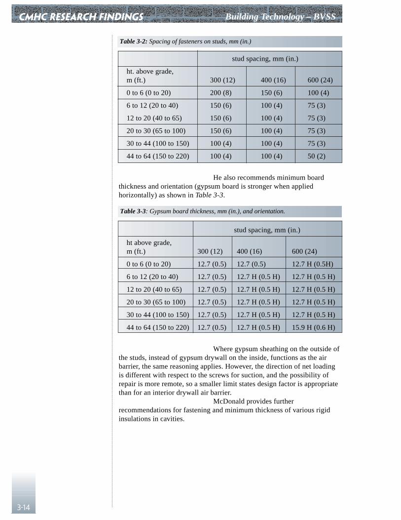
CMHC RESEARCH FINDINGS Building Technology – BVSS
3-14
stud spacing, mm (in.)
ht. above grade,m (ft.) 300 (12) 400 (16) 600 (24)
0 to 6 (0 to 20) 200 (8) 150 (6) 100 (4)
6 to 12 (20 to 40) 150 (6) 100 (4) 75 (3)
12 to 20 (40 to 65) 150 (6) 100 (4) 75 (3)
20 to 30 (65 to 100) 150 (6) 100 (4) 75 (3)
30 to 44 (100 to 150) 100 (4) 100 (4) 75 (3)
44 to 64 (150 to 220) 100 (4) 100 (4) 50 (2)
He also recommends minimum boardthickness and orientation (gypsum board is stronger when appliedhorizontally) as shown in Table 3-3.
stud spacing, mm (in.)
ht above grade,m (ft.) 300 (12) 400 (16) 600 (24)
0 to 6 (0 to 20) 12.7 (0.5) 12.7 (0.5) 12.7 H (0.5H)
6 to 12 (20 to 40) 12.7 (0.5) 12.7 H (0.5 H) 12.7 H (0.5 H)
12 to 20 (40 to 65) 12.7 (0.5) 12.7 H (0.5 H) 12.7 H (0.5 H)
20 to 30 (65 to 100) 12.7 (0.5) 12.7 H (0.5 H) 12.7 H (0.5 H)
30 to 44 (100 to 150) 12.7 (0.5) 12.7 H (0.5 H) 12.7 H (0.5 H)
44 to 64 (150 to 220) 12.7 (0.5) 12.7 H (0.5 H) 15.9 H (0.6 H)
Where gypsum sheathing on the outside ofthe studs, instead of gypsum drywall on the inside, functions as the airbarrier, the same reasoning applies. However, the direction of net loadingis different with respect to the screws for suction, and the possibility ofrepair is more remote, so a smaller limit states design factor is appropriatethan for an interior drywall air barrier.
McDonald provides furtherrecommendations for fastening and minimum thickness of various rigidinsulations in cavities.
Table 3-2: Spacing of fasteners on studs, mm (in.)
Table 3-3: Gypsum board thickness, mm (in.), and orientation.
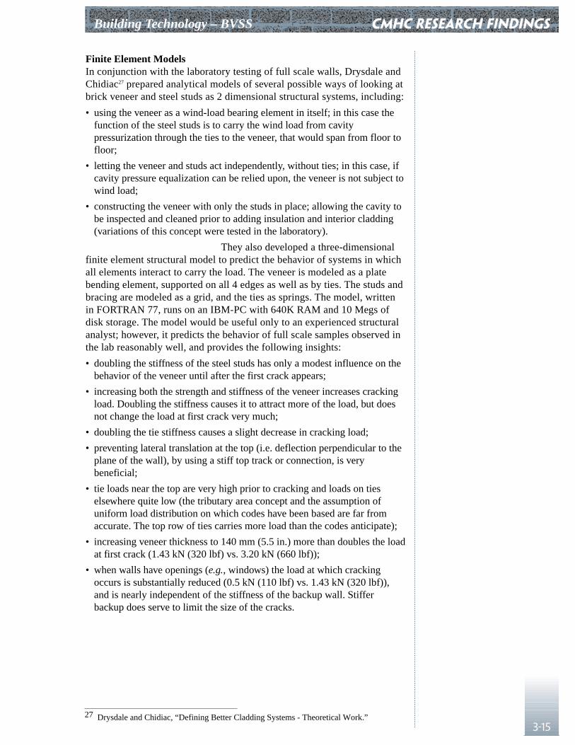
Building Technology – BVSS
3-15
Finite Element ModelsIn conjunction with the laboratory testing of full scale walls, Drysdale andChidiac27 prepared analytical models of several possible ways of looking atbrick veneer and steel studs as 2 dimensional structural systems, including:
• using the veneer as a wind-load bearing element in itself; in this case thefunction of the steel studs is to carry the wind load from cavitypressurization through the ties to the veneer, that would span from floor tofloor;
• letting the veneer and studs act independently, without ties; in this case, ifcavity pressure equalization can be relied upon, the veneer is not subject towind load;
• constructing the veneer with only the studs in place; allowing the cavity tobe inspected and cleaned prior to adding insulation and interior cladding(variations of this concept were tested in the laboratory).
They also developed a three-dimensionalfinite element structural model to predict the behavior of systems in whichall elements interact to carry the load. The veneer is modeled as a platebending element, supported on all 4 edges as well as by ties. The studs andbracing are modeled as a grid, and the ties as springs. The model, writtenin FORTRAN 77, runs on an IBM-PC with 640K RAM and 10 Megs ofdisk storage. The model would be useful only to an experienced structuralanalyst; however, it predicts the behavior of full scale samples observed inthe lab reasonably well, and provides the following insights:
• doubling the stiffness of the steel studs has only a modest influence on thebehavior of the veneer until after the first crack appears;
• increasing both the strength and stiffness of the veneer increases crackingload. Doubling the stiffness causes it to attract more of the load, but doesnot change the load at first crack very much;
• doubling the tie stiffness causes a slight decrease in cracking load;
• preventing lateral translation at the top (i.e. deflection perpendicular to theplane of the wall), by using a stiff top track or connection, is verybeneficial;
• tie loads near the top are very high prior to cracking and loads on tieselsewhere quite low (the tributary area concept and the assumption ofuniform load distribution on which codes have been based are far fromaccurate. The top row of ties carries more load than the codes anticipate);
• increasing veneer thickness to 140 mm (5.5 in.) more than doubles the loadat first crack (1.43 kN (320 lbf) vs. 3.20 kN (660 lbf));
• when walls have openings (e.g., windows) the load at which crackingoccurs is substantially reduced (0.5 kN (110 lbf) vs. 1.43 kN (320 lbf)),and is nearly independent of the stiffness of the backup wall. Stifferbackup does serve to limit the size of the cracks.
CMHC RESEARCH FINDINGS
27 Drysdale and Chidiac, “Defining Better Cladding Systems - Theoretical Work.”
RAIN28
RAIN is an IBM PC compatible computer program that grew out ofresearch investigating the pressure equalization of wall cavities underchanging pressure conditions in both a test chamber and a wind tunnel. Theprogram is based on the gas laws, and takes cavity depth and area (hencecompartment volume), backup wall flexibility and leakage, and claddingflexibility and vent area all into account as inputs. When these variablesare specified by the user, the program calculates the cavity pressure as afunction of time assuming a sawtooth function to describe the exteriorpressure. The program then presents the percentage of load carried by thecladding, the percentage carried by the backup, and the cavity pressure ona graph. It tabulates exterior pressure, cavity pressure, cladding load, airbarrier load, cavity volume, flow through the vents, and flow through theair barrier for a time period from 0 to 1.5 seconds (3 sawtooth cycles) in0.05 second intervals. RAIN was validated with the results of the workconducted in the test chamber. Its predictions agree reasonably well withmeasured cavity pressures in the exterior rain screen wall of one tallbuilding.29 The sawtooth frequency chosen simulates typical rates of loadand gust amplitude measured with pressure taps on actual buildings. Theprogram comes with excellent documentation and is easy to understandand operate.
By adjusting the inputs and examining theresults, the user quickly gets an appreciation for how sensitive theequalization of the cavity pressure is to different variables. If the cavityfails to track exterior pressure well, should one reduce the cavity volume,or increase the exterior vent area? If the air barrier leaks twice as much asexpected, what happens to the load on the cladding? These are questionsthat, without this program, are almost imponderable given ordinary designoffice resources. They are easy to explore with RAIN, permittingidentification of the best design options, and the construction defects mostlikely to cause problems. For instance, RAIN shows a performancedifference between open fibrous and closed cell insulation materials ofequivalent RSI (R value). Since air can move freely in and out of fibrousinsulation, its volume becomes part of the cavity volume, potentiallyreducing cavity pressure equalization.
Better tools may become available, astesting underway at CMHC and NRC/IRC proceeds. Meanwhile, thisprogram is easy to apply to the design of walls intended to function as rainscreens. It will provide improved quantification of important variables,such as the effect of compartment volume.
EMPTIED30
To establish a criterion for air leakage that was both buildable andadequate, CMHC and TROW developed EMPTIED, an IBM-PCcompatible computer program, to calculate condensation accumulated in awall over the course of several seasons. The program uses hourly BIN datafor each month to determine temperatures of selected surfaces inside the
CMHC RESEARCH FINDINGS Building Technology – BVSS
3-16
28 Morrison Hershfield, Rainscreen Concept Applied to Cladding Systems on Wood Frame Walls.
29 Place Air Canada, Montreal.30 TROW Inc. Criteria for The Air Leakage Characteristics of Building Envelopes.
Building Technology – BVSS
3-17
wall. It allows the user to specify a BIN data file (from files provided formajor Canadian cities), interior conditions of temperature and humidity(which the user can specify for each month), the thermal properties of thewall, a leakage area, and the maximum amounts of moisture that two user-specified condensation planes in the wall can store.
EMPTIED bases its calculations on theory,and makes several simplifying assumptions that may limit accuracy. It isbetter for comparing two different designs, or climates, than for predictingabsolute amounts of condensation. It assumes that the driving pressure forair leaking into the wall is the stack effect for a single floor heightdetermined hourly BIN by hourly BIN from the exterior temperature. Italso assumes that the path through the wall is sufficiently long that airreaches moisture equilibrium before exiting. For each month, the programcalculates amounts of condensation, evaporation, and moisture stored atthe two selected surfaces, and thereby determines how much must eitherdrain out or remain in the wall as water or ice not absorbed in materials.
The program always starts Year 1 withperfectly dry materials, so the effects of building with wet material cannotbe examined. Consecutive years can be run to see if surplus moisture islikely to carry over from year to year. Version 2.0 allows superimpositionof a constant pressure on stack effect, which is otherwise the only forcecausing air to pass into the wall, with flow governed by the leakage area ofthe tightest layer. Convective flow into and out of the wall on the same sideis not included. The program should be applied with these assumptions inmind. Nevertheless, it provides an interesting means of exploring thepotential influence of different designs on potential for accumulatedcondensation in a wall.
Other Sources of Information
The references listed at the end of thisguide include more sources of detailed information than have been alreadymentioned. The Canadian Building Digests, issued periodically for manyyears by the Division of Building Research (now the IRC) of NRC are abasic source of building technology information in Canada. IRC’s BuildingPractice Notes are also helpful. A good basic textbook for buildingtechnologists is Walls Windows & Roofs for the Canadian Climate.31 Amore advanced text, that will be of greater interest to engineers, or toarchitects who have kept up their mathematics, is Building Science for aCold Climate.32
CMHC RESEARCH FINDINGS
31 Latta.32 Hutcheon & Handegord.
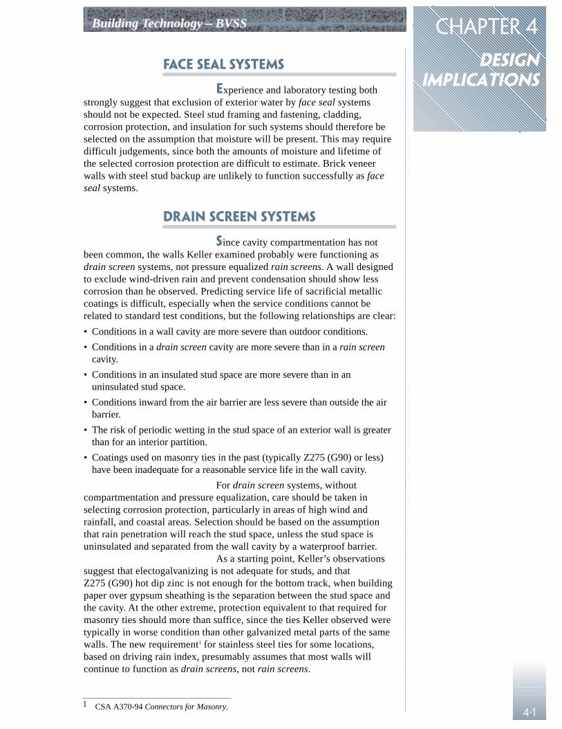
CHAPTER 4
designimplications
Building Technology – BVSS
4-1
Face Seal Systems
Experience and laboratory testing bothstrongly suggest that exclusion of exterior water by face seal systemsshould not be expected. Steel stud framing and fastening, cladding,corrosion protection, and insulation for such systems should therefore beselected on the assumption that moisture will be present. This may requiredifficult judgements, since both the amounts of moisture and lifetime ofthe selected corrosion protection are difficult to estimate. Brick veneerwalls with steel stud backup are unlikely to function successfully as faceseal systems.
Drain Screen Systems
Since cavity compartmentation has notbeen common, the walls Keller examined probably were functioning asdrain screen systems, not pressure equalized rain screens. A wall designedto exclude wind-driven rain and prevent condensation should show lesscorrosion than he observed. Predicting service life of sacrificial metalliccoatings is difficult, especially when the service conditions cannot berelated to standard test conditions, but the following relationships are clear:
• Conditions in a wall cavity are more severe than outdoor conditions.
• Conditions in a drain screen cavity are more severe than in a rain screencavity.
• Conditions in an insulated stud space are more severe than in anuninsulated stud space.
• Conditions inward from the air barrier are less severe than outside the airbarrier.
• The risk of periodic wetting in the stud space of an exterior wall is greaterthan for an interior partition.
• Coatings used on masonry ties in the past (typically Z275 (G90) or less)have been inadequate for a reasonable service life in the wall cavity.
For drain screen systems, withoutcompartmentation and pressure equalization, care should be taken inselecting corrosion protection, particularly in areas of high wind andrainfall, and coastal areas. Selection should be based on the assumptionthat rain penetration will reach the stud space, unless the stud space isuninsulated and separated from the wall cavity by a waterproof barrier.
As a starting point, Keller’s observationssuggest that electogalvanizing is not adequate for studs, and thatZ275 (G90) hot dip zinc is not enough for the bottom track, when buildingpaper over gypsum sheathing is the separation between the stud space andthe cavity. At the other extreme, protection equivalent to that required formasonry ties should more than suffice, since the ties Keller observed weretypically in worse condition than other galvanized metal parts of the samewalls. The new requirement1 for stainless steel ties for some locations,based on driving rain index, presumably assumes that most walls willcontinue to function as drain screens, not rain screens.
1 CSA A370-94 Connectors for Masonry.
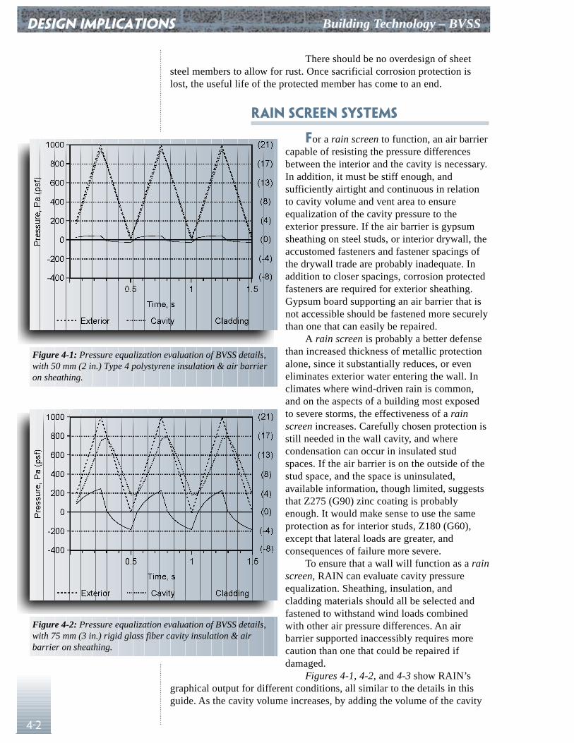
There should be no overdesign of sheetsteel members to allow for rust. Once sacrificial corrosion protection islost, the useful life of the protected member has come to an end.
Rain Screen Systems
For a rain screen to function, an air barriercapable of resisting the pressure differencesbetween the interior and the cavity is necessary.In addition, it must be stiff enough, andsufficiently airtight and continuous in relationto cavity volume and vent area to ensureequalization of the cavity pressure to theexterior pressure. If the air barrier is gypsumsheathing on steel studs, or interior drywall, theaccustomed fasteners and fastener spacings ofthe drywall trade are probably inadequate. Inaddition to closer spacings, corrosion protectedfasteners are required for exterior sheathing.Gypsum board supporting an air barrier that isnot accessible should be fastened more securelythan one that can easily be repaired.
A rain screen is probably a better defensethan increased thickness of metallic protectionalone, since it substantially reduces, or eveneliminates exterior water entering the wall. Inclimates where wind-driven rain is common,and on the aspects of a building most exposedto severe storms, the effectiveness of a rainscreen increases. Carefully chosen protection isstill needed in the wall cavity, and wherecondensation can occur in insulated studspaces. If the air barrier is on the outside of thestud space, and the space is uninsulated,available information, though limited, suggeststhat Z275 (G90) zinc coating is probablyenough. It would make sense to use the sameprotection as for interior studs, Z180 (G60),except that lateral loads are greater, andconsequences of failure more severe.
To ensure that a wall will function as a rainscreen, RAIN can evaluate cavity pressureequalization. Sheathing, insulation, andcladding materials should all be selected andfastened to withstand wind loads combinedwith other air pressure differences. An airbarrier supported inaccessibly requires morecaution than one that could be repaired ifdamaged.
Figures 4-1, 4-2, and 4-3 show RAIN’sgraphical output for different conditions, all similar to the details in thisguide. As the cavity volume increases, by adding the volume of the cavity
DESIGN IMPLICATIONS Building Technology – BVSS
4-2
Figure 4-1: Pressure equalization evaluation of BVSS details,with 50 mm (2 in.) Type 4 polystyrene insulation & air barrieron sheathing.
Figure 4-2: Pressure equalization evaluation of BVSS details,with 75 mm (3 in.) rigid glass fiber cavity insulation & airbarrier on sheathing.
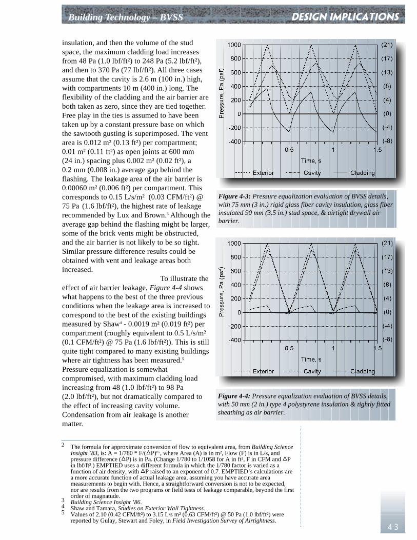
Building Technology – BVSS
4-3
insulation, and then the volume of the studspace, the maximum cladding load increasesfrom 48 Pa (1.0 lbf/ft²) to 248 Pa (5.2 lbf/ft²),and then to 370 Pa (77 lbf/ft²). All three casesassume that the cavity is 2.6 m (100 in.) high,with compartments 10 m (400 in.) long. Theflexibility of the cladding and the air barrier areboth taken as zero, since they are tied together.Free play in the ties is assumed to have beentaken up by a constant pressure base on whichthe sawtooth gusting is superimposed. The ventarea is 0.012 m² (0.13 ft²) per compartment;0.01 m² (0.11 ft²) as open joints at 600 mm(24 in.) spacing plus 0.002 m² (0.02 ft²), a0.2 mm (0.008 in.) average gap behind theflashing. The leakage area of the air barrier is0.00060 m² (0.006 ft²) per compartment. Thiscorresponds to 0.15 L/s/m² (0.03 CFM/ft²) @75 Pa (1.6 lbf/ft²), the highest rate of leakagerecommended by Lux and Brown.3 Although theaverage gap behind the flashing might be larger,some of the brick vents might be obstructed,and the air barrier is not likely to be so tight.Similar pressure difference results could beobtained with vent and leakage areas bothincreased.
To illustrate theeffect of air barrier leakage, Figure 4-4 showswhat happens to the best of the three previousconditions when the leakage area is increased tocorrespond to the best of the existing buildingsmeasured by Shaw4 - 0.0019 m² (0.019 ft²) percompartment (roughly equivalent to 0.5 L/s/m²(0.1 CFM/ft²) @ 75 Pa (1.6 lbf/ft²)). This is stillquite tight compared to many existing buildingswhere air tightness has been measured.5
Pressure equalization is somewhatcompromised, with maximum cladding loadincreasing from 48 (1.0 lbf/ft²) to 98 Pa(2.0 lbf/ft²), but not dramatically compared tothe effect of increasing cavity volume.Condensation from air leakage is anothermatter.
DESIGN IMPLICATIONS
2 The formula for approximate conversion of flow to equivalent area, from Building ScienceInsight ’83, is: A = 1/780 * F/(�P)0.5, where Area (A) is in m², Flow (F) is in L/s, andpressure difference (�P) is in Pa. (Change 1/780 to 1/1058 for A in ft², F in CFM and �Pin lbf/ft².) EMPTIED uses a different formula in which the 1/780 factor is varied as afunction of air density, with �P raised to an exponent of 0.7. EMPTIED’s calculations area more accurate function of actual leakage area, assuming you have accurate areameasurements to begin with. Hence, a straightforward conversion is not to be expected,nor are results from the two programs or field tests of leakage comparable, beyond the firstorder of magnatude.
3 Building Science Insight ’86.4 Shaw and Tamara, Studies on Exterior Wall Tightness.5 Values of 2.10 (0.42 CFM/ft²) to 3.15 L/s m² (0.63 CFM/ft²) @ 50 Pa (1.0 lbf/ft²) were
reported by Gulay, Stewart and Foley, in Field Investigation Survey of Airtightness.
Figure 4-3: Pressure equalization evaluation of BVSS details,with 75 mm (3 in.) rigid glass fiber cavity insulation, glass fiberinsulated 90 mm (3.5 in.) stud space, & airtight drywall airbarrier.
Figure 4-4: Pressure equalization evaluation of BVSS details,with 50 mm (2 in.) type 4 polystyrene insulation & tightly fittedsheathing as air barrier.
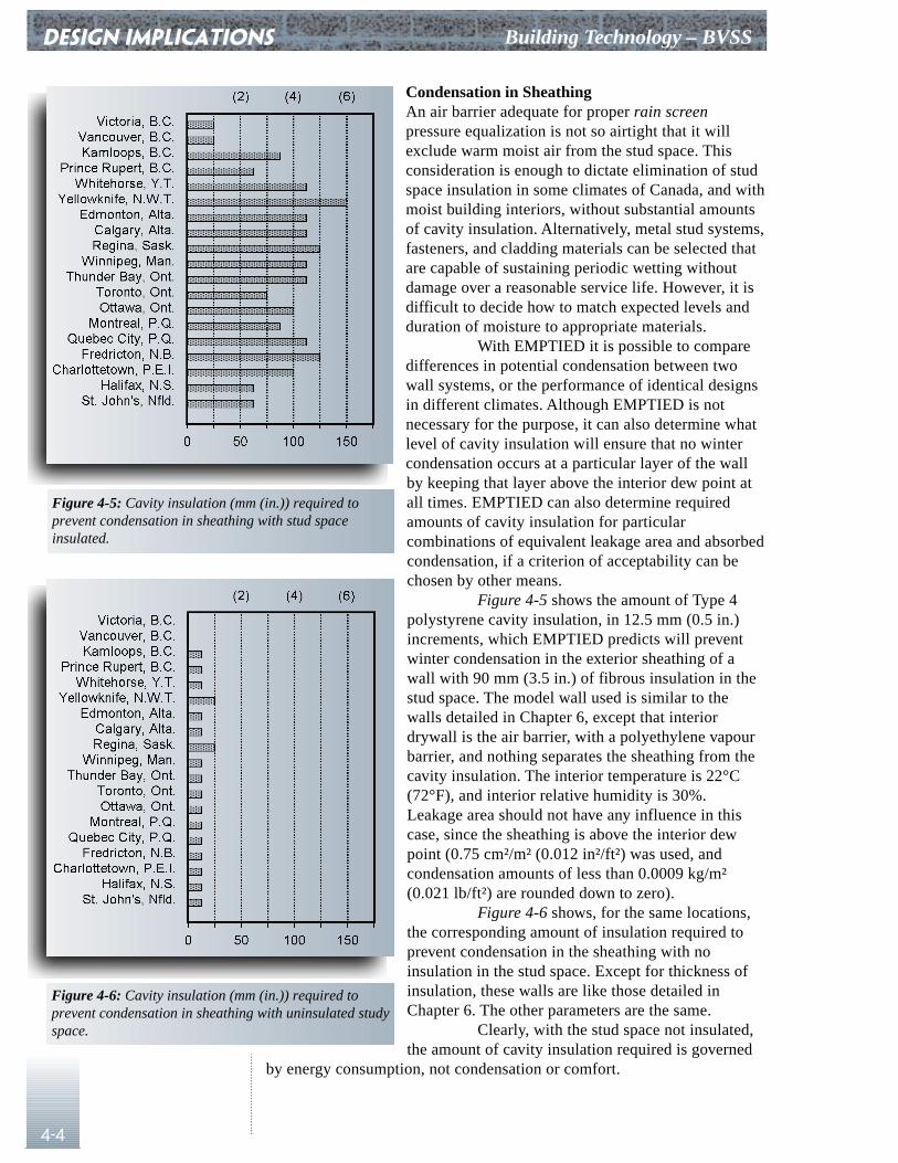
DESIGN IMPLICATIONS Building Technology – BVSS
4-4
Condensation in SheathingAn air barrier adequate for proper rain screenpressure equalization is not so airtight that it willexclude warm moist air from the stud space. Thisconsideration is enough to dictate elimination of studspace insulation in some climates of Canada, and withmoist building interiors, without substantial amountsof cavity insulation. Alternatively, metal stud systems,fasteners, and cladding materials can be selected thatare capable of sustaining periodic wetting withoutdamage over a reasonable service life. However, it isdifficult to decide how to match expected levels andduration of moisture to appropriate materials.
With EMPTIED it is possible to comparedifferences in potential condensation between twowall systems, or the performance of identical designsin different climates. Although EMPTIED is notnecessary for the purpose, it can also determine whatlevel of cavity insulation will ensure that no wintercondensation occurs at a particular layer of the wallby keeping that layer above the interior dew point atall times. EMPTIED can also determine requiredamounts of cavity insulation for particularcombinations of equivalent leakage area and absorbedcondensation, if a criterion of acceptability can bechosen by other means.
Figure 4-5 shows the amount of Type 4polystyrene cavity insulation, in 12.5 mm (0.5 in.)increments, which EMPTIED predicts will preventwinter condensation in the exterior sheathing of awall with 90 mm (3.5 in.) of fibrous insulation in thestud space. The model wall used is similar to thewalls detailed in Chapter 6, except that interiordrywall is the air barrier, with a polyethylene vapourbarrier, and nothing separates the sheathing from thecavity insulation. The interior temperature is 22°C(72°F), and interior relative humidity is 30%.Leakage area should not have any influence in thiscase, since the sheathing is above the interior dewpoint (0.75 cm²/m² (0.012 in²/ft²) was used, andcondensation amounts of less than 0.0009 kg/m²(0.021 lb/ft²) are rounded down to zero).
Figure 4-6 shows, for the same locations,the corresponding amount of insulation required toprevent condensation in the sheathing with noinsulation in the stud space. Except for thickness ofinsulation, these walls are like those detailed inChapter 6. The other parameters are the same.
Clearly, with the stud space not insulated,the amount of cavity insulation required is governed
by energy consumption, not condensation or comfort.
Figure 4-5: Cavity insulation (mm (in.)) required toprevent condensation in sheathing with stud spaceinsulated.
Figure 4-6: Cavity insulation (mm (in.)) required toprevent condensation in sheathing with uninsulated studyspace.
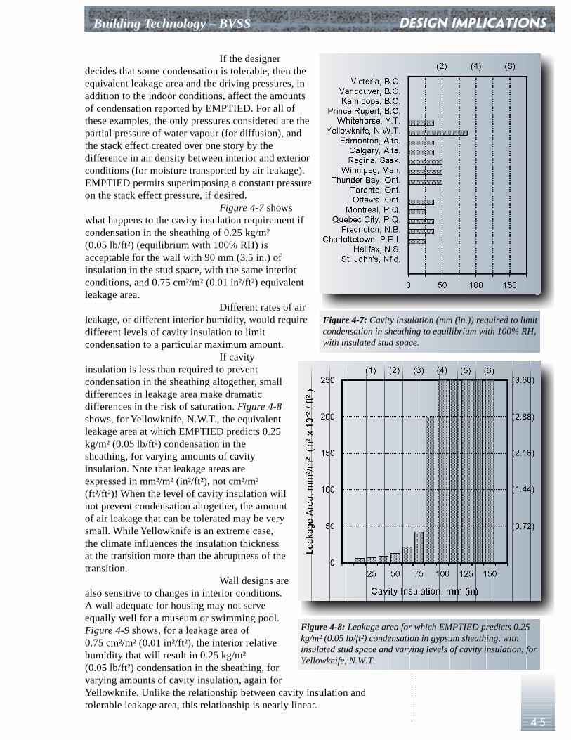
Building Technology – BVSS
4-5
If the designerdecides that some condensation is tolerable, then theequivalent leakage area and the driving pressures, inaddition to the indoor conditions, affect the amountsof condensation reported by EMPTIED. For all ofthese examples, the only pressures considered are thepartial pressure of water vapour (for diffusion), andthe stack effect created over one story by thedifference in air density between interior and exteriorconditions (for moisture transported by air leakage).EMPTIED permits superimposing a constant pressureon the stack effect pressure, if desired.
Figure 4-7 showswhat happens to the cavity insulation requirement ifcondensation in the sheathing of 0.25 kg/m²(0.05 lb/ft²) (equilibrium with 100% RH) isacceptable for the wall with 90 mm (3.5 in.) ofinsulation in the stud space, with the same interiorconditions, and 0.75 cm²/m² (0.01 in²/ft²) equivalentleakage area.
Different rates of airleakage, or different interior humidity, would requiredifferent levels of cavity insulation to limitcondensation to a particular maximum amount.
If cavityinsulation is less than required to preventcondensation in the sheathing altogether, smalldifferences in leakage area make dramaticdifferences in the risk of saturation. Figure 4-8shows, for Yellowknife, N.W.T., the equivalentleakage area at which EMPTIED predicts 0.25kg/m² (0.05 lb/ft²) condensation in thesheathing, for varying amounts of cavityinsulation. Note that leakage areas areexpressed in mm²/m² (in²/ft²), not cm²/m²(ft²/ft²)! When the level of cavity insulation willnot prevent condensation altogether, the amountof air leakage that can be tolerated may be verysmall. While Yellowknife is an extreme case,the climate influences the insulation thicknessat the transition more than the abruptness of thetransition.
Wall designs arealso sensitive to changes in interior conditions.A wall adequate for housing may not serveequally well for a museum or swimming pool.Figure 4-9 shows, for a leakage area of0.75 cm²/m² (0.01 in²/ft²), the interior relativehumidity that will result in 0.25 kg/m²(0.05 lb/ft²) condensation in the sheathing, forvarying amounts of cavity insulation, again forYellowknife. Unlike the relationship between cavity insulation andtolerable leakage area, this relationship is nearly linear.
DESIGN IMPLICATIONS
Figure 4-7: Cavity insulation (mm (in.)) required to limitcondensation in sheathing to equilibrium with 100% RH,with insulated stud space.
Figure 4-8: Leakage area for which EMPTIED predicts 0.25kg/m² (0.05 lb/ft²) condensation in gypsum sheathing, withinsulated stud space and varying levels of cavity insulation, forYellowknife, N.W.T.
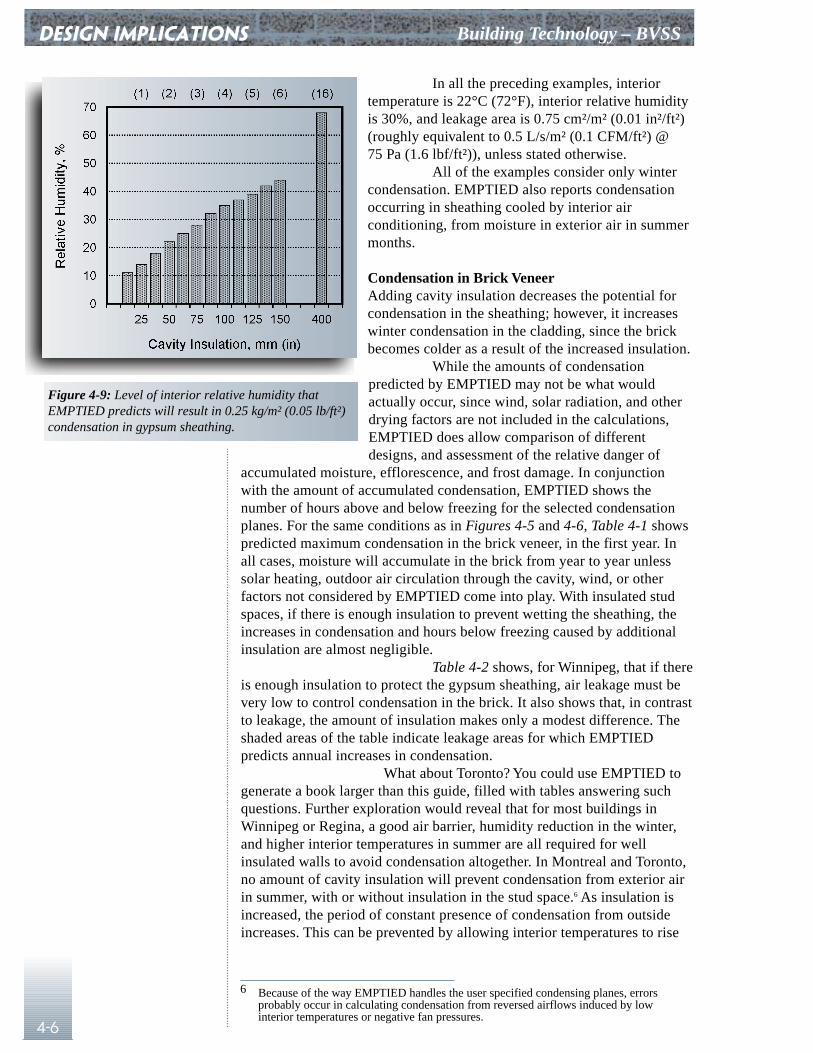
DESIGN IMPLICATIONS Building Technology – BVSS
4-6
In all the preceding examples, interiortemperature is 22°C (72°F), interior relative humidityis 30%, and leakage area is 0.75 cm²/m² (0.01 in²/ft²)(roughly equivalent to 0.5 L/s/m² (0.1 CFM/ft²) @75 Pa (1.6 lbf/ft²)), unless stated otherwise.
All of the examples consider only wintercondensation. EMPTIED also reports condensationoccurring in sheathing cooled by interior airconditioning, from moisture in exterior air in summermonths.
Condensation in Brick VeneerAdding cavity insulation decreases the potential forcondensation in the sheathing; however, it increaseswinter condensation in the cladding, since the brickbecomes colder as a result of the increased insulation.
While the amounts of condensationpredicted by EMPTIED may not be what wouldactually occur, since wind, solar radiation, and otherdrying factors are not included in the calculations,EMPTIED does allow comparison of differentdesigns, and assessment of the relative danger of
accumulated moisture, efflorescence, and frost damage. In conjunctionwith the amount of accumulated condensation, EMPTIED shows thenumber of hours above and below freezing for the selected condensationplanes. For the same conditions as in Figures 4-5 and 4-6, Table 4-1 showspredicted maximum condensation in the brick veneer, in the first year. Inall cases, moisture will accumulate in the brick from year to year unlesssolar heating, outdoor air circulation through the cavity, wind, or otherfactors not considered by EMPTIED come into play. With insulated studspaces, if there is enough insulation to prevent wetting the sheathing, theincreases in condensation and hours below freezing caused by additionalinsulation are almost negligible.
Table 4-2 shows, for Winnipeg, that if thereis enough insulation to protect the gypsum sheathing, air leakage must bevery low to control condensation in the brick. It also shows that, in contrastto leakage, the amount of insulation makes only a modest difference. Theshaded areas of the table indicate leakage areas for which EMPTIEDpredicts annual increases in condensation.
What about Toronto? You could use EMPTIED togenerate a book larger than this guide, filled with tables answering suchquestions. Further exploration would reveal that for most buildings inWinnipeg or Regina, a good air barrier, humidity reduction in the winter,and higher interior temperatures in summer are all required for wellinsulated walls to avoid condensation altogether. In Montreal and Toronto,no amount of cavity insulation will prevent condensation from exterior airin summer, with or without insulation in the stud space.6 As insulation isincreased, the period of constant presence of condensation from outsideincreases. This can be prevented by allowing interior temperatures to rise
6 Because of the way EMPTIED handles the user specified condensing planes, errors probably occur in calculating condensation from reversed airflows induced by low interior temperatures or negative fan pressures.
Figure 4-9: Level of interior relative humidity thatEMPTIED predicts will result in 0.25 kg/m² (0.05 lb/ft²)condensation in gypsum sheathing.
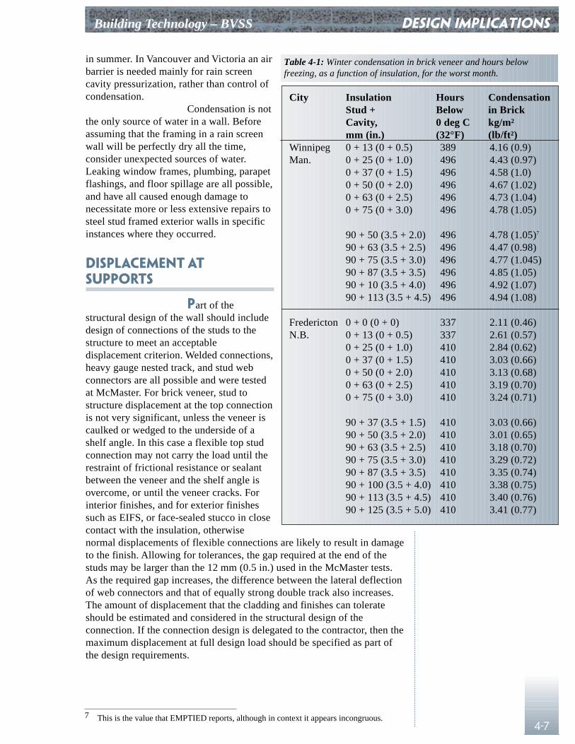
Building Technology – BVSS
4-7
in summer. In Vancouver and Victoria an airbarrier is needed mainly for rain screencavity pressurization, rather than control ofcondensation.
Condensation is notthe only source of water in a wall. Beforeassuming that the framing in a rain screenwall will be perfectly dry all the time,consider unexpected sources of water.Leaking window frames, plumbing, parapetflashings, and floor spillage are all possible,and have all caused enough damage tonecessitate more or less extensive repairs tosteel stud framed exterior walls in specificinstances where they occurred.
Displacement atSupports
Part of thestructural design of the wall should includedesign of connections of the studs to thestructure to meet an acceptabledisplacement criterion. Welded connections,heavy gauge nested track, and stud webconnectors are all possible and were testedat McMaster. For brick veneer, stud tostructure displacement at the top connectionis not very significant, unless the veneer iscaulked or wedged to the underside of ashelf angle. In this case a flexible top studconnection may not carry the load until therestraint of frictional resistance or sealantbetween the veneer and the shelf angle isovercome, or until the veneer cracks. Forinterior finishes, and for exterior finishessuch as EIFS, or face-sealed stucco in closecontact with the insulation, otherwisenormal displacements of flexible connections are likely to result in damageto the finish. Allowing for tolerances, the gap required at the end of thestuds may be larger than the 12 mm (0.5 in.) used in the McMaster tests.As the required gap increases, the difference between the lateral deflectionof web connectors and that of equally strong double track also increases.The amount of displacement that the cladding and finishes can tolerateshould be estimated and considered in the structural design of theconnection. If the connection design is delegated to the contractor, then themaximum displacement at full design load should be specified as part ofthe design requirements.
DESIGN IMPLICATIONS
City Insulation Hours CondensationStud + Below in BrickCavity, 0 deg C kg/m²mm (in.) (32°F) (lb/ft²)
Winnipeg 0 + 13 (0 + 0.5) 389 4.16 (0.9)Man. 0 + 25 (0 + 1.0) 496 4.43 (0.97)
0 + 37 (0 + 1.5) 496 4.58 (1.0)0 + 50 (0 + 2.0) 496 4.67 (1.02)0 + 63 (0 + 2.5) 496 4.73 (1.04)0 + 75 (0 + 3.0) 496 4.78 (1.05)
90 + 50 (3.5 + 2.0) 496 4.78 (1.05)7
90 + 63 (3.5 + 2.5) 496 4.47 (0.98)90 + 75 (3.5 + 3.0) 496 4.77 (1.045)90 + 87 (3.5 + 3.5) 496 4.85 (1.05)90 + 10 (3.5 + 4.0) 496 4.92 (1.07)90 + 113 (3.5 + 4.5) 496 4.94 (1.08)
Fredericton 0 + 0 (0 + 0) 337 2.11 (0.46)N.B. 0 + 13 (0 + 0.5) 337 2.61 (0.57)
0 + 25 (0 + 1.0) 410 2.84 (0.62)0 + 37 (0 + 1.5) 410 3.03 (0.66)0 + 50 (0 + 2.0) 410 3.13 (0.68)0 + 63 (0 + 2.5) 410 3.19 (0.70)0 + 75 (0 + 3.0) 410 3.24 (0.71)
90 + 37 (3.5 + 1.5) 410 3.03 (0.66)90 + 50 (3.5 + 2.0) 410 3.01 (0.65)90 + 63 (3.5 + 2.5) 410 3.18 (0.70)90 + 75 (3.5 + 3.0) 410 3.29 (0.72)90 + 87 (3.5 + 3.5) 410 3.35 (0.74)90 + 100 (3.5 + 4.0) 410 3.38 (0.75)90 + 113 (3.5 + 4.5) 410 3.40 (0.76)90 + 125 (3.5 + 5.0) 410 3.41 (0.77)
7 This is the value that EMPTIED reports, although in context it appears incongruous.
Table 4-1: Winter condensation in brick veneer and hours belowfreezing, as a function of insulation, for the worst month.
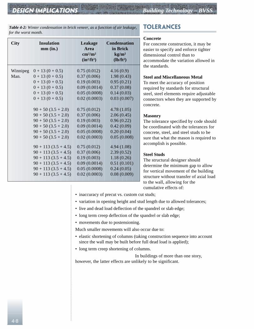
DESIGN IMPLICATIONS Building Technology – BVSS
4-8
Tolerances
ConcreteFor concrete construction, it may beeasier to specify and enforce tighterdimensional control than toaccommodate the variation allowed inthe standards.
Steel and Miscellaneous MetalTo meet the accuracy of positionrequired by standards for structuralsteel, steel elements require adjustableconnectors when they are supported byconcrete.
MasonryThe tolerance specified by code shouldbe coordinated with the tolerances forconcrete, steel, and steel studs to besure that what the mason is required toaccomplish is possible.
Steel StudsThe structural designer shoulddetermine the minimum gap to allowfor vertical movement of the buildingstructure without transfer of axial loadto the wall, allowing for thecumulative effects of:
• inaccuracy of precut vs. custom cut studs;
• variation in opening height and stud length due to allowed tolerances;
• live and dead load deflection of the spandrel or slab edge;
• long term creep deflection of the spandrel or slab edge;
• movements due to postensioning.
Much smaller movements will also occur due to:
• elastic shortening of columns (taking construction sequence into accountsince the wall may be built before full dead load is applied);
• long term creep shortening of columns.
In buildings of more than one story,however, the latter effects are unlikely to be significant.
City Insulation Leakage Condensationmm (in.) Area in Brick
cm²/m² kg/m²(in²/ft²) (lb/ft²)
Winnipeg 0 + 13 (0 + 0.5) 0.75 (0.012) 4.16 (0.9)Man. 0 + 13 (0 + 0.5) 0.37 (0.006) 1.98 (0.43)
0 + 13 (0 + 0.5) 0.19 (0.003) 0.95 (0.21)0 + 13 (0 + 0.5) 0.09 (0.0014) 0.37 (0.08)0 + 13 (0 + 0.5) 0.05 (0.0008) 0.14 (0.03)0 + 13 (0 + 0.5) 0.02 (0.0003) 0.03 (0.007)
90 + 50 (3.5 + 2.0) 0.75 (0.012) 4.78 (1.05)90 + 50 (3.5 + 2.0) 0.37 (0.006) 2.06 (0.45)90 + 50 (3.5 + 2.0) 0.19 (0.003) 0.96 (0.22)90 + 50 (3.5 + 2.0) 0.09 (0.0014) 0.42 (0.09)90 + 50 (3.5 + 2.0) 0.05 (0.0008) 0.20 (0.04)90 + 50 (3.5 + 2.0) 0.02 (0.0003) 0.05 (0.008)
90 + 113 (3.5 + 4.5) 0.75 (0.012) 4.94 (1.08)90 + 113 (3.5 + 4.5) 0.37 (0.006) 2.39 (0.52)90 + 113 (3.5 + 4.5) 0.19 (0.003) 1.18 (0.26)90 + 113 (3.5 + 4.5) 0.09 (0.0014) 0.51 (0.101)90 + 113 (3.5 + 4.5) 0.05 (0.0008) 0.24 (0.05)90 + 113 (3.5 + 4.5) 0.02 (0.0003) 0.08 (0.009)
Table 4-2: Winter condensation in brick veneer, as a function of air leakage,for the worst month.
Building Technology – BVSS
4-9
The Last Word?
Research at CMHC and elsewhere isongoing. The final say on design implications of knowledge gained fromresearch and from observation of performance of existing buildings willnever be heard. There is always room for more information.
Current prospects include research onwetting patterns on buildings during wind-driven rain, suggested byobservations published in the 1970s by NRC.8 Better understanding ofwhere wind-driven rain strikes buildings may make it possible to fine tuneefforts to keep rain out of various parts of the enclosure, depending onlocation. Some parts of walls may not need to be rain screens because theynever get wet. Other parts may require more attention than they get today,because of the extent of their exposure.
Investigation of design and performance ofrain screens is also ongoing. While changes of exterior pressure with timehave been considered here, the frequency with which such changes occurcould be considered in more detail, and spatial variation of exteriorpressure over the building surface could be taken into account. Futurelaboratory tests, wind measurements, and pressure measurements incavities of buildings in service will give a clearer picture of the extent towhich cavity pressure equalization can be achieved in practice, and of thecompartment sizes required on various parts of a building. A betterknowledge of the spatial and temporal distribution of transient pressuresmay reveal a need for smaller compartments than would be selected basedon time-averaged pressure distributions.
Tolerances, both usual and economicallypossible, are another area in which more knowledge would be helpful.
Application
Chapter 6 presents details and discussionshowing how these design implications can be applied to design a wall fora particular set of environmental and structural circumstances.
DESIGN IMPLICATIONS
8 Robinson and Baker, Wind-Driven Rain and Buildings.
CHAPTER 5
qualityassurance
5-1
Commissioning
Detailing and specifying a carefullydesigned wall is not enough to ensure that it will perform as expected whenbuilt. Measurement of material thicknesses, zinc coating weights, brick andmortar properties, and visual inspection for missing parts or improperassembly procedures are all reasonably well understood aspects of qualityassurance. Standards for the materials establish test procedures foracceptance or rejection of suspect parts or materials, and shop drawings orcontract documents show how to assemble them. There are no widelyaccepted procedures for verification of air leakage performance of anassembled wall, yet this factor is critical to satisfactory performance anddurability. All the following precautions should be considered as means ofensuring expected performance.
PrototypeTesting a prototype of the wall for air leakage at the pressure used tospecify acceptable performance will ensure that unrealistic goals are notbuilt into a contract. The test pressure should be 50 (1.0 lbf/ft²) or 75 Pa(1.6 lbf/ft²), depending on available equipment, and on how acceptableleakage will be specified. Fifty Pascals (1.0 lbf/ft²) is the referencepressure used for evaluation of R2000 homes, so fan door equipment isavailable designed for use at this pressure. While 75 Pa (1.6 lbf/ft²) may bedifficult to maintain, it has the advantage of being the reference pressurefor requirements proposed for the 1995 edition of the NBC. The ability ofthe prototype to withstand design wind loads without distress should alsobe tested if possible without substantial added expense. People who haveused steel stud construction for plenums know that unexpected problemscan arise when the fans are turned on and the full design load is applied.Wall builders may have to wait many years to discover their errors, unlessa prototype is tested. Construction difficulties may appear that were notevident on the drawings or in specifications. They can be corrected withoutundue expense at this stage. The inspector for the construction phaseshould be involved in the test, to take advantage of experience building andtesting the prototype during the construction phase. If a prototype is testedbefore working drawings are completed and put out to bid, the designercan be assured that the design is capable of being constructed andperforming as anticipated, and bidders for the project need not fear havingto meet an impossible performance requirement. Prior experience buildingand testing projects with essentially the same design, if it is available, maybe better than testing a prototype.
Mock-upOnce a builder is selected, a jobsite mock-up provides opportunity for thecontractor to evaluate adequacy of chosen construction methods, and trainpersonnel to be able to meet the performance requirement. If there are noprototype tests or prior experience with the same design, the mock-up canserve the purpose of verifying the design, but any required adjustmentsmay be expensive at this stage, if they involve changes to the contract.Extensive failures to meet performance requirements can be avoided if theworkers and supervisors who will be responsible for the rest of the projectbuild the mock-up, observed by the design personnel who participated in
Building Technology – BVSS
QUALITY ASSURANCE Building Technology – BVSS
5-2
testing the prototype. Building the mock-up permits fine tuning ofconstruction procedures. Testing it allows the contractor to verify that therequired performance is possible.
Ongoing InspectionPeriodic inspection of ongoing work will catch any drift away from thetested construction procedures and materials, and deal with anyunanticipated special conditions. Accuracy of location of studs and shelfangles, attachment and connections, and provisions for movement shouldbe checked periodically before the drywaller can conceal errors oromissions, and before the mason discovers inaccuracies the hard way.
Final InspectionA qualitative check of all completed work is necessary to verify that nosignificant air leaks have been overlooked. Smoke generators, smokepencils, acoustics, thermography, or a combination can locate significantproblems that random selection of areas for quantitative testing might miss.Experienced inspection personnel will have a good feel for what worksbest. Detection, not measurement, of unusual air leakage is the object. Themethods used are only as important as their effectiveness at pinpointingleaks of a different order of magnitude from the required overallperformance.
Compliance TestingFull testing to measure air leakage performance of randomly selected areasis the most reliable way to verify compliance. The tested areas should berepresentative, not selected on the basis of expectations about particularareas. Ideally, enough samples should be tested to allow statisticalevaluation of the variance. The contractor should not have the opportunityto police an area specifically designated for testing. Neither should thedesigner take the liberty of testing a suspect area. Unusually leaky areasshould be found by qualitative testing and corrected before this final phase.If the floors of the building are not subdivided into rooms, then test awhole floor.
A procedure for this last test, which servesto verify that the contractor has matched the air leakage performance of theprototype, is suggested by Gulay et al.1
In an apartment building with identicalplans on successive floors, a single apartment can be tested by using onefan to pressurize (or depressurize) the test suite, with measured air flow,while using additional fans and pressure sensors to maintain matchingpressures in the adjoining suites, left, right, above, and below, and in thehallway. If there are no unknown paths leading to other parts of thebuilding, the flow required to maintain test suite pressure is the flowthrough the exterior wall. Before the test is done all ducted supply andexhaust vents are sealed. Depending on how the performance criterion isspecified, it may be necessary to seal the windows, taking care not to sealthe juncture between the window frame and the wall, if leakage at thatlocation is regarded as part of the wall leakage. While the test suite andadjacent spaces are equalized, use of a smoke pencil will detect possiblepaths to non-equalized spaces, so that they can be sealed.
1 Gulay, Stewart and Foley, Field Investigation Survey of Airtightness.
CHAPTER 6
details andspecifications
6-1
Cad drawing files
The details presented here are included asCAD drawing files on the accompanying CD-ROM.
The wall shown was conceived as a rainscreen. The details are intended to illustrate responses to the issuesdiscussed in Chapters 2, 3, and 4. The particular design parameters arearbitrary. An actual building design would differ in response to some otherunique set of conditions, since different buildings have different interiorenvironments, exterior environments, and structural frames, all of whichaffect the BVSS design.
Building Frame
The building frame is reinforced concrete.Around the perimeter of the building the distance between columns isabout 2.4 m (8 ft.). The floor to underside of slab height is 2440 mm (8 ft.),and the soffit of the structural slab forms the finished ceiling adjacent tothe exterior wall. The structural designer says that the total verticalmovement to be accommodated by the wall framing is 5 mm (0.2 in.), atmid-span. The floors are not post-tensioned, so no access is required to theedges of the structural slabs. This set of conditions falls near the lowerlimit of vertical movement that steel stud wall connections might need toaccommodate. The alternative slab edge in Detail 2 would allow for 15 mm(0.6 in.) of vertical slab edge deflection, permitting wider column spacing.
Thermal and Moisture Protection
At the building location, 75 mm (3 in.) ofcavity insulation is required to avoid condensation on the sheathing of anuninsulated stud space. Exterior temperatures of -30°C (-20°F) are possiblebut not frequent. This is more than enough insulation to provide thermalcomfort, but energy conservation might require more. Interior relativehumidity is expected to be 30% or less, with normal interior temperature of22°C (72°F). A peel and stick (modified asphalt and polyethylene)membrane serves as air barrier, vapour barrier, and cavity flashing. Withthis air barrier on the outside, low air leakage is expected. Sealing thebarrier around the brick ties will be important to ensure this. The successof this approach needs to be confirmed by building and testing a prototypebefore extensive use of the details. Reducing the cavity volume ensurescavity pressure equalization, compared to an airtight drywall approach.Use of extruded polystyrene foam insulation further limits the cavityvolume.
Drywall sheathing supports the air barriermembrane. Normal fastening of the sheathing will not be enough to ensureattachment for the life of the building. If a major windstorm dislodges thesheathing, it is more serious than with an interior air barrier, since accessfor repair would require dismantling the wall. Hence, plated fasteners at100 mm (4 in.) o.c. secure the sheathing along each stud, to ensure that theair barrier remains in place under design wind + stack + fan loading.
Building Technology – BVSS
DETAILS AND SPECIFICATIONS Building Technology – BVSS
6-2
Because the insulation is a closed cellfoam, it is fastened more securely than usual, to ensure that changes in airpressure in the cavity do not create temporary pressures behind theinsulation capable of dislodging it. Air pervious insulation would notrequire as much fastening, but would require other adjustments to thedesign, because of increased cavity volume. In any case, fastening must becapable of pulling the insulation into uniform contact with the insulatedsurface to minimize gaps between the insulation and the air barrier.
Proprietary plastic washers on the brickties hold the rigid insulation against the sheathing so that it spans from tieto tie. In a milder climate, with thinner insulation, the brick ties might betoo far apart for this to work. Mechanical fasteners into the sheathing,tested to ensure they would not cause leaks in the air barrier, would be analternative.
There will rarely be any potential forcondensation on the back of the exterior sheathing. Hence, Z275 (G90)zinc coating is enough for sheet steel components, other than masonry ties,and steel fasteners are zinc plated. There is no polyethylene behind theinterior drywall, and no special effort to seal the interior drywall. The airbarrier also serves as vapour barrier. If windows or plumbing leak, or ifthere is water on the floor, water that finds its way into the stud space willhave an opportunity to evaporate. The bottom track might be made of moreheavily galvanized material, to allow for moisture collecting there. Theusual variable gap is left undisturbed at the bottom of the interior drywall,and joints are taped only as required for decorative and fire resistivepurposes. Interior drywall is omitted where partitions intersect the exteriorwall, and in service spaces, except when required for fire-resistance. Theinterior drywall is fastened with screws at standard spacing.
Provision for Movement
There is less provision for movement thanis usually required. The 10 mm (0.4 in.) clear joint beneath the shelf anglewill provide for 5 mm (0.2 in.) of combined column creep shortening andslab deflection, corresponding to perimeter column spacing and floor tofloor dimensions of about 2.5 m (100 in.), plus 1.5 mm (0.06 in.) of brickexpansion with aging, and 3.5 mm (0.138 in.) for good measure. Allowingfor the full 5 mm (0.2 in.) in every case takes into account the possibilitythat one floor might carry the full live load while adjoining floors remainunloaded. In order to use sealant instead of flashing, a joint of 20 mm(0.8 in.) or more would be required between the shelf angle and the top ofbrick, depending on the compression the selected sealant couldaccommodate.
The 5 mm (0.2 in.) minimum gap betweenthe top edge of the drywall and the soffit, and also between the leg of theouter track and the highest screw heads where the studs are secured to theinner track, allows for movement of the structural frame. The air barriermanufacturer has advised that the membrane can span such a gap andaccommodate the expected movement.
If studs are pre-cut to length toaccommodate indicated tolerances in the slab position, then in addition to structural movement, a gap from end of stud to slab of up to
Building Technology – BVSS
6-3
45 mm (1.8 in.) would be required. This does not include a tolerance forcutting the studs. The nested track arrangement shown cannotaccommodate so large a gap, unless the outer track is quite heavy. Too light a track would allow excessive inward movement under full wind load. Hence, the studs will be pre-cut to the most extreme length, requiringmany studs to be cut shorter as they are installed.
The open joint between the top of theveneer and the underside of the shelf angle, behind flashing, providesadditional cavity ventilation sheltered from water on the surface, andavoids restraining lateral deflection of the veneer. There are no open headjoints for ventilation, since lab tests have demonstrated that they allowwater to enter the cavity, even with pressure equalization, under conditionsof wind driven rain. Water entering the joints during rain is a greater threatthan failure of water vapour to leave by the same route under dryingconditions.
Shelf Angle
The shelf angle is aligned with thenominal slab soffit elevation, allowing ceiling-high windows withoutlintels or brickwork between the window head and the shelf angle. Theshelf could be inverted to avoid difficulties with the flashings atconnections, and, if required, to permit access to postensioninganchorages.
The attachment shown for the shelf angleallows location accurate enough to avoid unsightly undulations in themasonry, while accommodating all slab edge positions permitted by thetolerances. The shelf angle tolerance is the usual tolerance specified foradjustable steel framing members. This location also provides thermalseparation from the slab edge. Detail 2 shows a shimmed and grouted shelfangle without thermal separation.
The face of the exterior sheathing isnominally in line with the slab edge, to allow a bit of extra room foradjustment in cases where the slab edge is at the inward extreme position.When the slab is fully retracted, the bottom track projects somewhat, butthe minimum fastener to slab edge distance is still available for drilledconcrete screws.
At corners the shelf angle is mitred andwelded. Shelf angle joints are located at control joint/compartmentlocations near corners, and at intervals along the wall, to minimize fieldwelding. For humid, rainy, or coastal locations, where it might benecessary to galvanize the shelf angle, bolted connections should be usedin place of welded connections.
Brick Ties
The brick ties are attached to the sides ofthe studs, with fasteners acting in shear (stronger than fasteners acting intension). The ties will not cause local bending of the stud flanges, andtwisting of studs is minimized. Where the ties penetrate the sheathing, theair barrier is patched with pieces of peel-and-stick membrane. The ties aregalvanized after fabrication, because there will be more moisture in the
details and specifications
DETAILS AND SPECIFICATIONS Building Technology – BVSS
6-4
cavity than in the stud space. For coastal climates, they would be stainlesssteel. The ties provide maximum stiffness over a range of adjustment, andtransfer load directly to the web of the stud. The ties are spaced inaccordance with CAN3-A3711, but designed so that the top row of ties willcarry 50% of the wind load for one floor, to ensure that they will not beoverloaded before the veneer cracks.2 Additional ties at openings and edgesare kept 200 mm (8 in.) away from the edge of the veneer. Extra studs areprovided at these locations, to support the added ties.
Cavity
Since the cladding is brick veneer, thenominal cavity width is 50 mm (2 in.), and some exterior water will getinto the cavity by gravity, despite the rain screen. To minimize thispossibility, vents into the cavity are located only at the shelf angle; thejoint below the shelf angle is sheltered by the flashing above. In Drysdale’stests, vents located above the bottom of the cavity admitted substantialamounts of water.3 Alternatively, the joint could be caulked, in which caseopen joints or vents might be added to encourage ventilation, but theseopenings would have to be sheltered. A stiffer top connection for the studsmight be necessary as well since the sealant would accommodate lesslateral movement. Either way, water running down the exterior face willnot have much opportunity to enter the top of the cavity by gravity flow.Where it enters the vents at the shelf angle, it will meet flashing that has tobe fully sealed in any event.
To avoid a cavity plugged with fallenmortar and debris, the bottom of the cavity could be filled for the first fewcourses with free-draining gravel. This method is one of severalrecommended by Drysdale and Suter4, and has been in use in some casesfor several years without evident adverse effects. Several other methodscommonly specified in the past are less satisfactory. Pulling a board upthrough the cavity might work if ties were installed progressively, and ifthe cavity was always the same size, but this is not the case. Pulling ropesout of the vents suffers from a timing difficulty; if they are pulled out whenthe mortar is plastic, subsequent plugging of the holes is possible. When astory of brickwork is completed, the mortar at the bottom has set and therope is trapped. Another method that is reported to work well is leaving outevery third brick in the first course, until after all mortar has been cleanedout through the resulting openings. This permits inspection of the cavityjust prior to closure of the openings.
At corners, and at 10 m (33 ft.) intervals(coinciding with every other brick expansion joint) vertical baffles areinstalled to limit cavity volume and ensure pressure equalization ismaintained. RAIN was used to evaluate the spacing. Larger or morefrequent brick vents would be required, perhaps along with morecompartments, if fibrous insulation were used, since its volume is mostlyair, or if an airtight drywall approach had been taken that would add the
1 CAN3-A371, Masonry Construction for Buildings.2 Under CAN/CSA S304 Masonry Design for Buildings, every tie is required to be able to
carry a load equal to 40% of the tributary load on an area equal to wall height x stud spacing. Making the top row of ties stronger is an option for the building structural designer to consider as part of a detailed stiffness analysis.
3 Drysdale and Wilson, McMaster, Part 5.4 Drysdale and Suter, Exterior Wall Construction in High Rise Buildings.
Building Technology – BVSS
6-5
volume of the stud space to the cavity. The shelf angles act as horizontalbaffles. The shelf angle at the roof line and the double baffles at cornerscreate smaller compartments at points where exterior pressures varysubstantially over short distances, and where wind-driven rain impingeswith greater intensity, compared to the rest of the facade.
Structural Considerations
Welded connections are worthconsidering, if welders experienced in sheet steel welding and the properequipment are both available.
The minimum stud thickness specified willbe 1.22 mm (18 ga.), or that selected from the manufacturer’s table for theL/720 deflection criterion, if thicker. The thicknesses and attachments ofall of the components will receive the detailed attention of a structuralengineer at the shop drawing stage. Where there are no openings, theveneer will crack at about the design wind load. If this happens, crackwidth and additional ingress of water into the cavity will be acceptableprovided the rain screen pressure equalization is effective. The engineerresponsible for the shop drawings will design and detail the headconnection and additional reinforcement at openings, but is not likely touse a heavier stud than the minimum specified.
SI Units Imperial Units Detail 1 - SLAB EDGE
Most of the features of this detail havebeen mentioned already. Notes describing parts that are repeated in otherdetails generally appear only here, and are not repeated in the other details.
TolerancesThe detail can be built, without compromising function, when thecomponents are located within the ranges indicated. All components areshown in their nominal position. In specific instances, the face of studmight be 22.7 mm (0.9 in.) inward from the grid, with the edge of slab afurther 2.3 mm (0.09 in.) inward, or projecting 47.7 mm (1.9 in.) outwardfrom the face of stud. The air space, shown as 54 mm (2.1 in.), mightactually be anywhere from 39 mm (1.5 in.) to 69 mm (2.7 in.). Theseextremes are consistent with the tolerances specified in the applicablestandards, except that the concrete structure has been given more latitude,based on experience and the reject rate implied in the Appendix to CSAA23.1. The shelf angles should be carefully adjusted and secured beforethe metal stud framing is installed, so that the toe of the shelf angle canserve as a reference for the location of the framing. An assortment of wiretie sizes accommodates the full range of cavity dimensions. Installing thestud framing by measuring from the slab edge, rather than the toe of theadjusted shelf angle, would make it impossible to maintain both areasonable air space and a visually flat exterior wall surface.
details and specifications
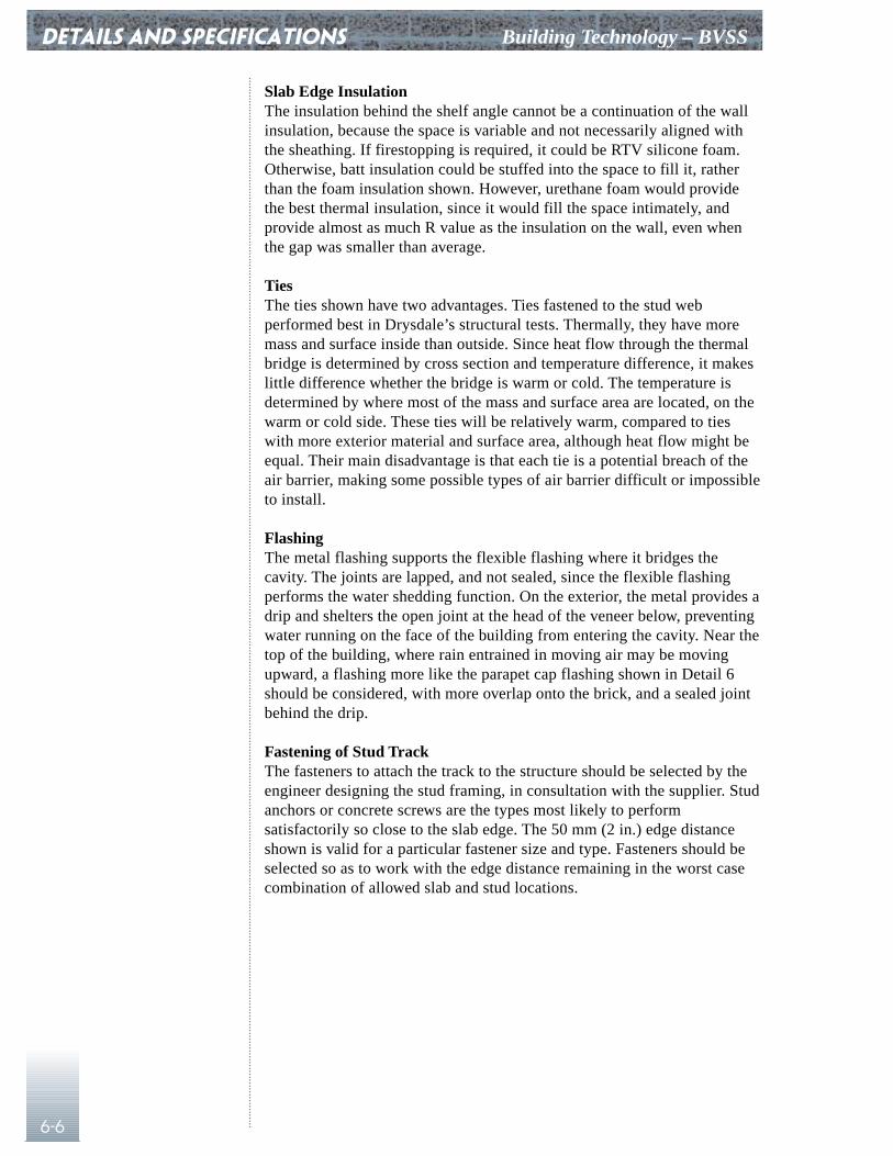
DETAILS AND SPECIFICATIONS Building Technology – BVSS
6-6
Slab Edge InsulationThe insulation behind the shelf angle cannot be a continuation of the wallinsulation, because the space is variable and not necessarily aligned withthe sheathing. If firestopping is required, it could be RTV silicone foam.Otherwise, batt insulation could be stuffed into the space to fill it, ratherthan the foam insulation shown. However, urethane foam would providethe best thermal insulation, since it would fill the space intimately, andprovide almost as much R value as the insulation on the wall, even whenthe gap was smaller than average.
TiesThe ties shown have two advantages. Ties fastened to the stud webperformed best in Drysdale’s structural tests. Thermally, they have moremass and surface inside than outside. Since heat flow through the thermalbridge is determined by cross section and temperature difference, it makeslittle difference whether the bridge is warm or cold. The temperature isdetermined by where most of the mass and surface area are located, on thewarm or cold side. These ties will be relatively warm, compared to tieswith more exterior material and surface area, although heat flow might beequal. Their main disadvantage is that each tie is a potential breach of theair barrier, making some possible types of air barrier difficult or impossibleto install.
FlashingThe metal flashing supports the flexible flashing where it bridges thecavity. The joints are lapped, and not sealed, since the flexible flashingperforms the water shedding function. On the exterior, the metal provides adrip and shelters the open joint at the head of the veneer below, preventingwater running on the face of the building from entering the cavity. Near thetop of the building, where rain entrained in moving air may be movingupward, a flashing more like the parapet cap flashing shown in Detail 6should be considered, with more overlap onto the brick, and a sealed jointbehind the drip.
Fastening of Stud TrackThe fasteners to attach the track to the structure should be selected by theengineer designing the stud framing, in consultation with the supplier. Studanchors or concrete screws are the types most likely to performsatisfactorily so close to the slab edge. The 50 mm (2 in.) edge distanceshown is valid for a particular fastener size and type. Fasteners should beselected so as to work with the edge distance remaining in the worst casecombination of allowed slab and stud locations.
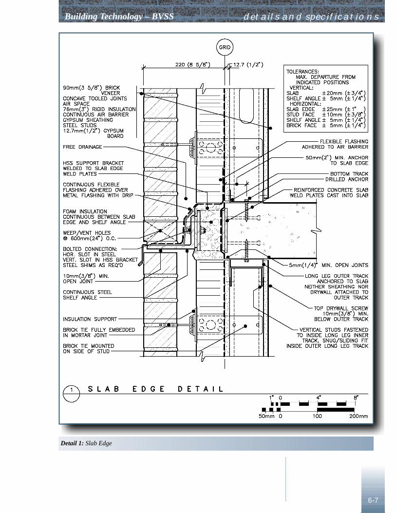
Building Technology – BVSS
6-7
details and specifications
Detail 1: Slab Edge
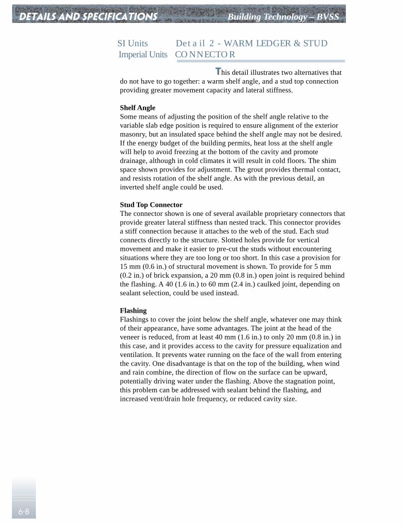
DETAILS AND SPECIFICATIONS Building Technology – BVSS
6-8
SI Units Detail 2 - WARM LEDGER & STUD Imperial Units CONNECTOR
This detail illustrates two alternatives thatdo not have to go together: a warm shelf angle, and a stud top connectionproviding greater movement capacity and lateral stiffness.
Shelf AngleSome means of adjusting the position of the shelf angle relative to thevariable slab edge position is required to ensure alignment of the exteriormasonry, but an insulated space behind the shelf angle may not be desired.If the energy budget of the building permits, heat loss at the shelf anglewill help to avoid freezing at the bottom of the cavity and promotedrainage, although in cold climates it will result in cold floors. The shimspace shown provides for adjustment. The grout provides thermal contact,and resists rotation of the shelf angle. As with the previous detail, aninverted shelf angle could be used.
Stud Top ConnectorThe connector shown is one of several available proprietary connectors thatprovide greater lateral stiffness than nested track. This connector providesa stiff connection because it attaches to the web of the stud. Each studconnects directly to the structure. Slotted holes provide for verticalmovement and make it easier to pre-cut the studs without encounteringsituations where they are too long or too short. In this case a provision for15 mm (0.6 in.) of structural movement is shown. To provide for 5 mm(0.2 in.) of brick expansion, a 20 mm (0.8 in.) open joint is required behindthe flashing. A 40 (1.6 in.) to 60 mm (2.4 in.) caulked joint, depending onsealant selection, could be used instead.
FlashingFlashings to cover the joint below the shelf angle, whatever one may thinkof their appearance, have some advantages. The joint at the head of theveneer is reduced, from at least 40 mm (1.6 in.) to only 20 mm (0.8 in.) inthis case, and it provides access to the cavity for pressure equalization andventilation. It prevents water running on the face of the wall from enteringthe cavity. One disadvantage is that on the top of the building, when windand rain combine, the direction of flow on the surface can be upward,potentially driving water under the flashing. Above the stagnation point,this problem can be addressed with sealant behind the flashing, andincreased vent/drain hole frequency, or reduced cavity size.
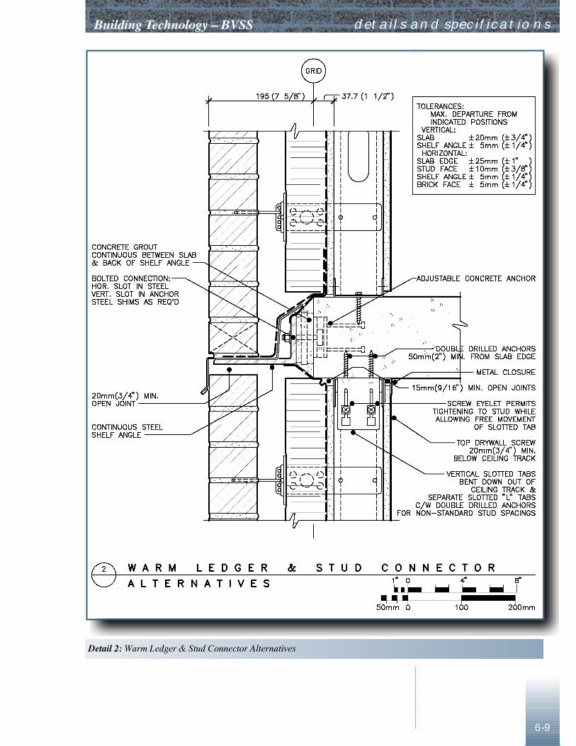
������������ � ���������
6-9
details and specifications
���������������������� ������������������������
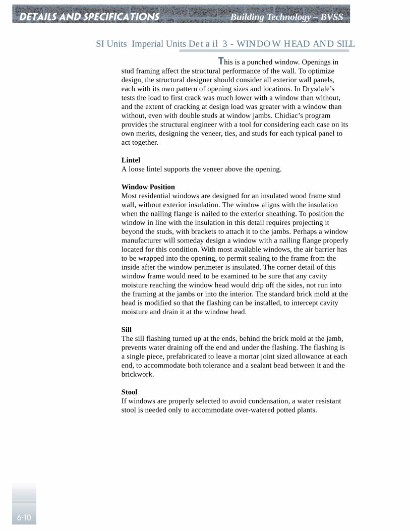
DETAILS AND SPECIFICATIONS Building Technology – BVSS
6-10
SI Units Imperial Units Detail 3 - WINDOW HEAD AND SILL
This is a punched window. Openings instud framing affect the structural performance of the wall. To optimizedesign, the structural designer should consider all exterior wall panels,each with its own pattern of opening sizes and locations. In Drysdale’stests the load to first crack was much lower with a window than without,and the extent of cracking at design load was greater with a window thanwithout, even with double studs at window jambs. Chidiac’s programprovides the structural engineer with a tool for considering each case on itsown merits, designing the veneer, ties, and studs for each typical panel toact together.
LintelA loose lintel supports the veneer above the opening.
Window PositionMost residential windows are designed for an insulated wood frame studwall, without exterior insulation. The window aligns with the insulationwhen the nailing flange is nailed to the exterior sheathing. To position thewindow in line with the insulation in this detail requires projecting itbeyond the studs, with brackets to attach it to the jambs. Perhaps a windowmanufacturer will someday design a window with a nailing flange properlylocated for this condition. With most available windows, the air barrier hasto be wrapped into the opening, to permit sealing to the frame from theinside after the window perimeter is insulated. The corner detail of thiswindow frame would need to be examined to be sure that any cavitymoisture reaching the window head would drip off the sides, not run intothe framing at the jambs or into the interior. The standard brick mold at thehead is modified so that the flashing can be installed, to intercept cavitymoisture and drain it at the window head.
SillThe sill flashing turned up at the ends, behind the brick mold at the jamb,prevents water draining off the end and under the flashing. The flashing isa single piece, prefabricated to leave a mortar joint sized allowance at eachend, to accommodate both tolerance and a sealant bead between it and thebrickwork.
StoolIf windows are properly selected to avoid condensation, a water resistantstool is needed only to accommodate over-watered potted plants.
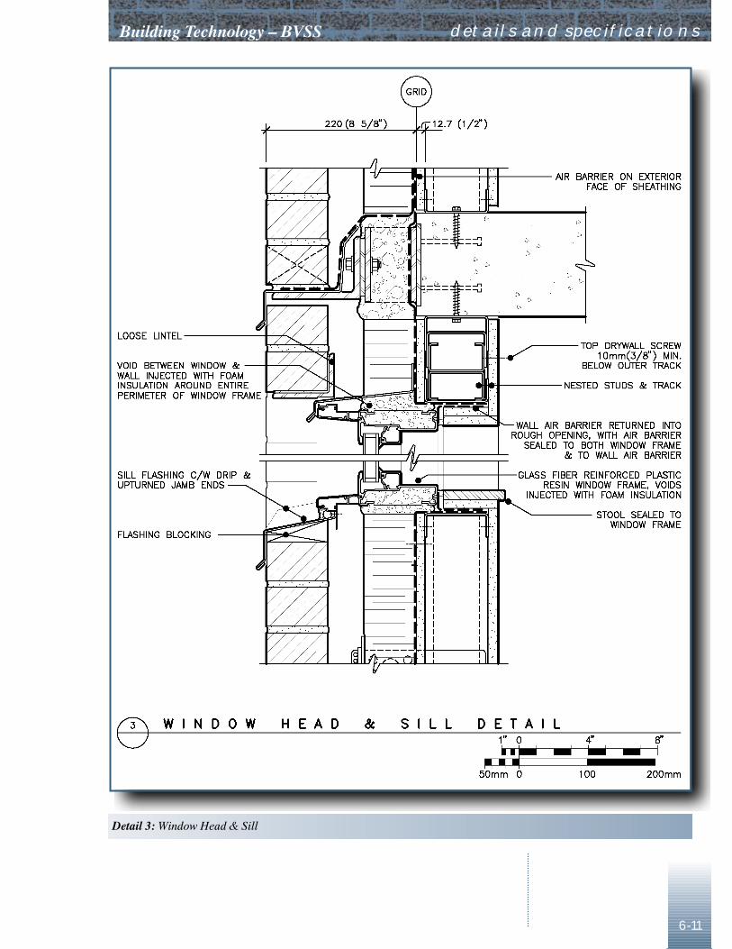
������������ � ���������
6-11
details and specifications
����������������������
DETAILS AND SPECIFICATIONS Building Technology – BVSS
6-12
SI Units Imperial Units Detail 4 - WINDOW AT U/S SLAB
This is still a punched window, but placedas close to the ceiling as possible. A strip window would require structuralsupports spanning from column to column below the sill, or hot rolledmembers cantilevered from the floor slab, with different provisions forstructural movement and window attachment, and an additional shelf anglein line with the sill for any panels of brick between windows.
The window is attached to the wall, but thedrywall at the window head is attached to the slab. Therefore, joints arerequired in line with both jambs, extending to underside of slab, and at thewindow head, between the window frame and the drywall, to provide formovement of the ceiling and drywall attached to it relative to the wall andwindow frame.
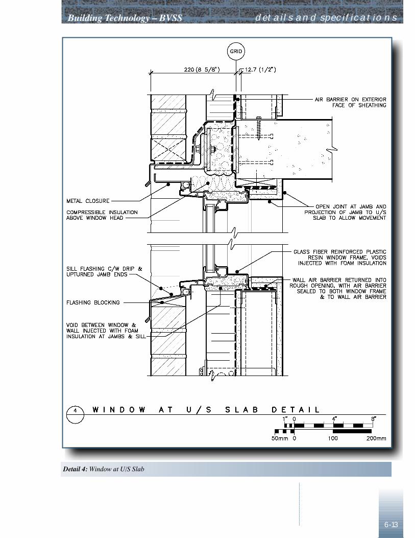
������������ � ���������
6-13
details and specifications
��������������������� ��
DETAILS AND SPECIFICATIONS Building Technology – BVSS
6-14
SI Units Imperial Units Detail 5 - WINDOW JAMB
The window is supported by metalbrackets attached to the window jamb, and to doubled studs at the jamb ofthe opening. (Structural design might dictate something other than doublestuds.) The window is installed after the air barrier has been wrapped intothe opening. Connection to the window is made with additional strips of airbarrier applied from the interior, over the support brackets.
An additional stud and ties support the edge of the veneerat both sides of the opening, 200 mm (8 in.) away from the opening. Airleakage at ties is prevented by using Band-Aids of air barrier materialsealed to each tie, to the air barrier, and to each other above and belowthe tie.
Bridging in the stud space is mechanicallyattached, or welded, to the studs.
Foam insulation around the window couldbe replaced with batt insulation stuffed into the space between the windowframe and the cavity insulation; however, the higher thermal conductivityof fibrous insulation might result in glass edge temperatures lower than theinterior dew point.
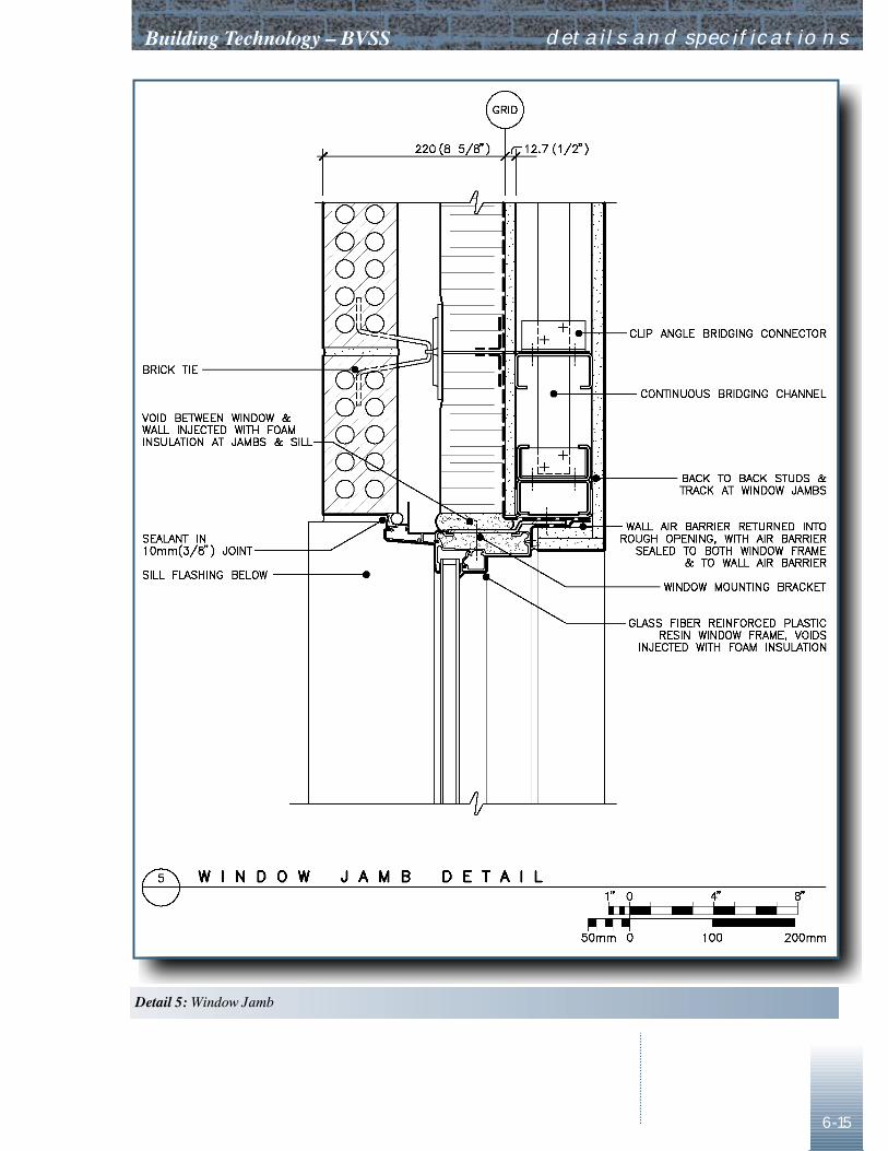
������������ � ���������
6-15
details and specifications
�������������������
DETAILS AND SPECIFICATIONS Building Technology – BVSS
6-16
SI Units Imperial Units Detail 6 - LOW PARAPET
Shelf AngleThere is a shelf angle at the roof line for two reasons. If there were no shelfangle, the brick veneer would be attached to both the top of the stud walland to the parapet. These two elements deflect differently in response toboth wind and snow loadings. The top of stud connection is where lateraldeflection in response to wind is normally at its maximum. If the shelfangle is omitted, a detailed structural analysis would be needed to be sureexcessive cracking of the veneer would not occur. The shelf angle alsoseparates the cavity into two regions with different thermal and moistureregimes. In the parapet the cavity is unheated, and does not receivecondensed moisture from air leakage. In the wall cavity there is some heatloss from the wall, as well as air leakage. If the two cavities are connected,a convection current in the air space is likely to transport moisture into theparapet, and concentrate condensation there.
InsulationWith insulated parapets, where the insulation goes up and over the parapet,designers assume that the structure of the parapet will be warm as a resultof the insulation. A two-dimensional heat flow analysis will probably showthat this is not true, unless the parapet is very low or made of veryconductive material. In this case, the edge of the roof slab will still be cold,because the plate supporting the parapet acts as a thermal bridge, but notcolder than it would be with a conventional hollow framed insulatedparapet. An alternative connection might be devised to provide a thermalbreak if slab temperature remains a concern.
SupportThe bent plate support shown for the parapet is robust enough to surviveimpacts from gravel buggies, and to allow swing stage outriggers to rest ontop. A hollow parapet framed in steel stud cannot withstand these forces, oreven wind loads, unless structurally supported along the top by steel orconcrete supports attached to the roof slab. This narrow parapet requiresless flashing material, and can be positioned to accommodate the toleranceallowed for the location of the slab edge, in addition to being selfsupporting.
CompartmentationLike the wall cavities, the parapet cavity needs to be compartmented,particularly at corners, to ensure pressure equalization and reduce rainpenetration. The same compartment spacing used in the wall should extendthrough the parapet cavity.
FlashingThe top of the parapet is sloped to prevent puddles on top. Waterproofbituminous flashings underneath make caulking of joints in the metalneither necessary nor desirable. Metal flashings should be fabricated insections short enough that fastening is only required in the S-lock joints atthe ends, without clips in the hem that are often difficult to install, andomitted as a result. Caulking between the back of the flashing and the faceof the wall will prevent entry of wind-driven rain, usually traveling upward
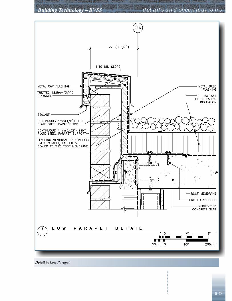
������������ � ���������
6-17
details and specifications
�������� ����������
DETAILS AND SPECIFICATIONS Building Technology – BVSS
6-18
at the top of a building. The sealant will tear at the joints in the flashingunless it is discontinuous at each joint, or debonded from the flashing foran interval.
RoofingEach roofing type will require different detailing. This roof is hot-meltrubberized asphalt, inverted, and reinforced with EPDM sheet embedded inthe membrane over the joint with the parapet support and over joints in theparapet support.
SI Units Detail 7 - SLAB EDGE ATImperial Units FOUNDATION
This detail provides continuity ofinsulation between the wall and the foundation wall. If the grade is sloping,coordinate steps in the shelf angle with brick expansion joint/cavitycompartment locations. A metal closure at sides of steps can close thecavity. In some geographic localities, corbels or thick foundations are oftenused to support brickwork at grade. Except for the resulting thermalbridge, this is a perfectly acceptable alternative that may avoid an unusualrecess at grade, and allow a sloping grade to be followed more evenly bythe bottom of the brickwork. The difference between tolerances possible inconcrete and those required in brickwork needs to be considered in thiscase, to ensure that steps and corbels are aligned with the brick coursing.Thick bed joints or awkwardly cut brick or both will result if normalconcrete tolerances are applied.
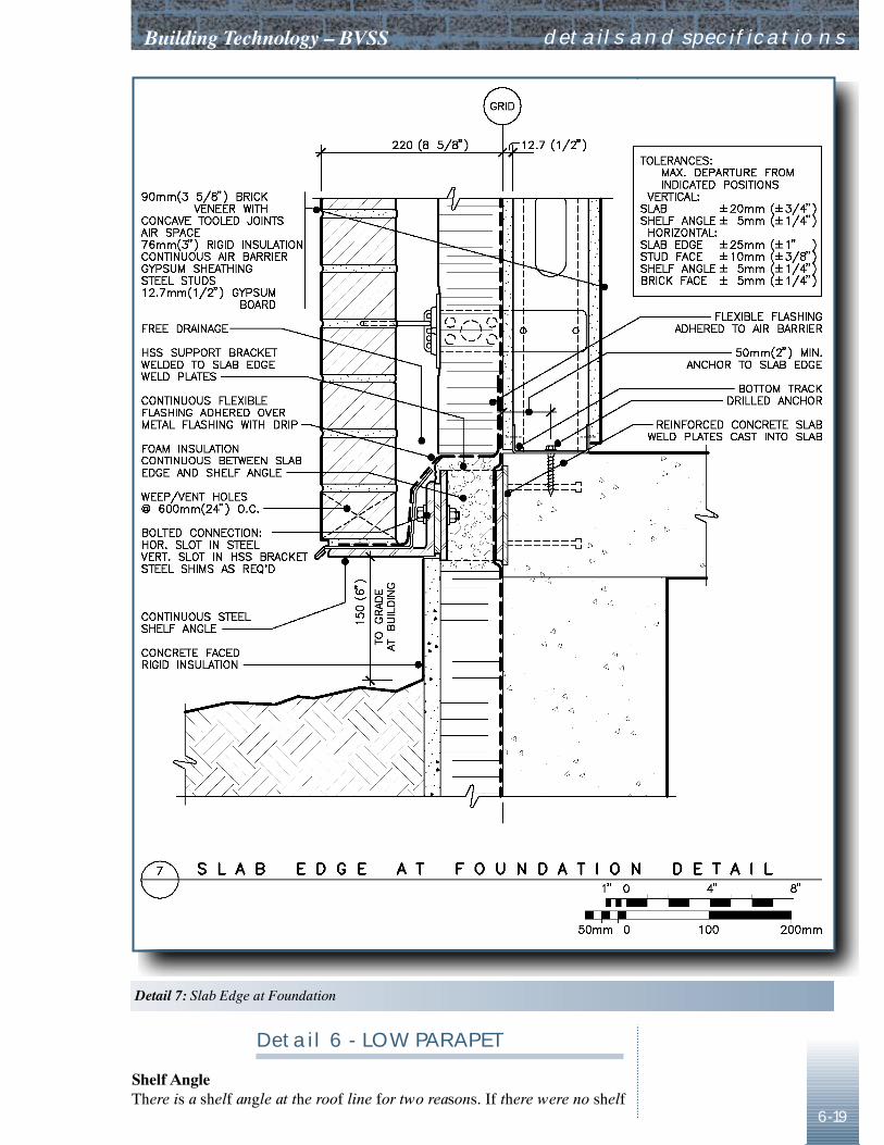
������������ � ���������
6-19
details and specifications
Detail 6 - LOW PARAPET
������������������������ ����� ������������ ��������������������������������������� �
�������� ������������� ������
DETAILS AND SPECIFICATIONS Building Technology – BVSS
6-20
SI Units Detail 8 - BALCONY ATImperial Units PATIO DOOR
This detail shows how to eliminate someof the problems that often occur with the common cantilevered balcony,without radical change. An ideal balcony would avoid the cantilevered slabaltogether. For some owners this is a requirement. This would eliminate thethermal bridge of the slab itself. A space between the two slabs wouldallow continuous insulation. Elimination of the perimeter radiation wouldallow elimination of the curb at the threshold, permitting wheelchair accessand making pedestrian access much more convenient.
CurbThe curb extends for the full width of the cantilevered slab, and supportswaterproofing as well as the patio door. Because of the large size of thedoor, it is better to provide different cladding above and below the opening,rather than having a punched opening in the brickwork. Perimeter hotwater radiation is kept simple by running it past the door on the inside ofthe curb, eliminating either additional risers, or the need for a drop ceilingon the floor below, with an offset in the piping. With door and wallsdesigned for high thermal efficiency, it might be possible to eliminate theperimeter radiation altogether.
Instead of the concrete curb shown, thecurb could be built of metal stud, with the top channel designed as a beamto carry lateral loads across the width of the opening. Metal stud framing isunlikely to be adequate unless specifically designed for the loadstransferred from the door to the curb.
DripsA drip is needed not only at the edge of the balcony, but also near the wallline, since concrete balconies often leak through cracks, with watersometimes running along the underside of the slab, adhered by surfacetension, and then into the wall.
Perimeter Fastening of Air BarrierFree edges of the waterproofing/air barrier should be mechanicallyfastened through metal battens. In this case they would be described in thespecifications for the air barrier.
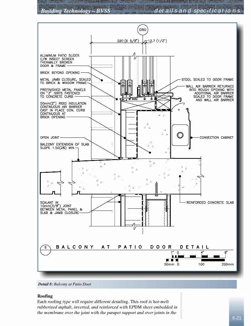
������������ � ���������
6-21
������������������������ ��� !����������������� ��������������������"�� �!�����#�������� $���%����$����������������������&'������������������������������%������(�������������������!����������%���(����������
details and specifications
�������� �������������������
DETAILS AND SPECIFICATIONS Building Technology – BVSS
6-22
SI Units Imperial Units Detail 9 - CORNER
Corner CompartmentsWind loads on cavity dividers are greatest at corners, because the mostsevere gradients in pressure occur at corners. By using two dividers similarto the those used in mid-wall, the load is divided and the corner appearssymmetrical. The barriers shown are 400 mm (16 in.) from the corner.They could be up to 600 mm (24 in.) away from the corner, particularly ifthe building is large. The brickwork at the corner is supported by its ownshelf angle, mitred and welded at the corner, with a joint, if required,located at one of the vertical expansion joints.
Fastening at Sides The studs, bracing, and inner top track of the wall framing are all fastenedto the column. This provides redundancy, protects the interior finish frombeing crushed or cracked, and protects the air barrier from movementbetween adjoining substrata. The connection of the inner top track to thecolumn will also prevent racking in the plane of the wall framing.
AlignmentThe column will not always be in line with the sheathing. A 30 mm(1.2 in.) misalignment is possible within tolerance. In most cases there willbe a step and joint in the insulation as a result, and the compartmentdividers will have to be trimmed to suit the dimensions of each case.
Sealing DividersNo de facto standard based on satisfactory experience has yet evolved for sealing compartment dividers. At the wall surface an added strip ofpeel-and-stick membrane does the job well. The same material can be usedto seal the ends to the shelf angles; remember to leave room for movement.The slotted foam joint backer shown would be custom made from billets ofpolyethylene foam. Alternatives that have been suggested are to providetwo caulked joints, so the edge of the divider is visible at the wall surface,or to fasten the divider mechanically to the edge of the brickwork on oneside of the joint, with sealant or a gasket to seal the divider to the brick.Each suggestion has potential difficulties, such as misalignment with thewall face, rusty edges, or unwanted restraint of the brickwork. However thedivider is sealed, it needs to be reasonably airtight although not perhaps asair tight as the air barrier. Just projecting it into the joint with a gapbetween the divider and the back of the joint sealant would allow air to doan end run between compartments and defeat the purpose of the divider.
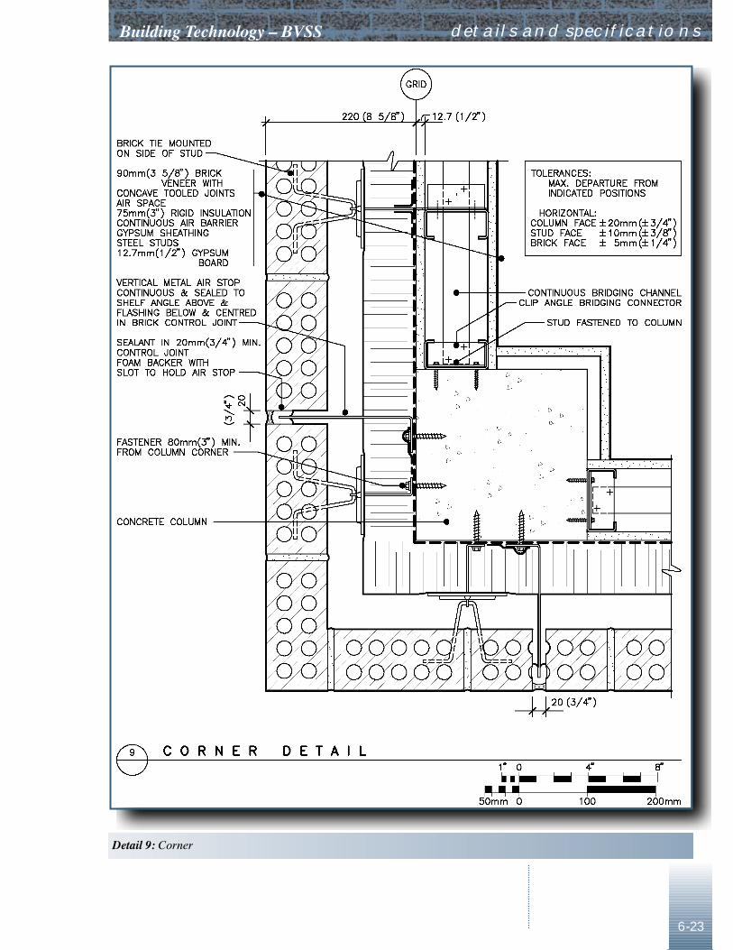
������������ � ���������
6-23
details and specifications
�������� )�����

DETAILS AND SPECIFICATIONS Building Technology – BVSS
6-24
SI Units Imperial Units Detail 10 - CONTROL JOINT
Here the compartment barrier fastens tothe stud framing, rather than to the concrete frame. An additional stud isrequired at this location for attachment. To provide redundancy, andprevent differential lateral deflection, the stud framing should always befastened to the structure at abutments like this column. If the barrier ismechanically attached to the brick, rather than as in this detail, thestructural effect on the veneer should be considered.
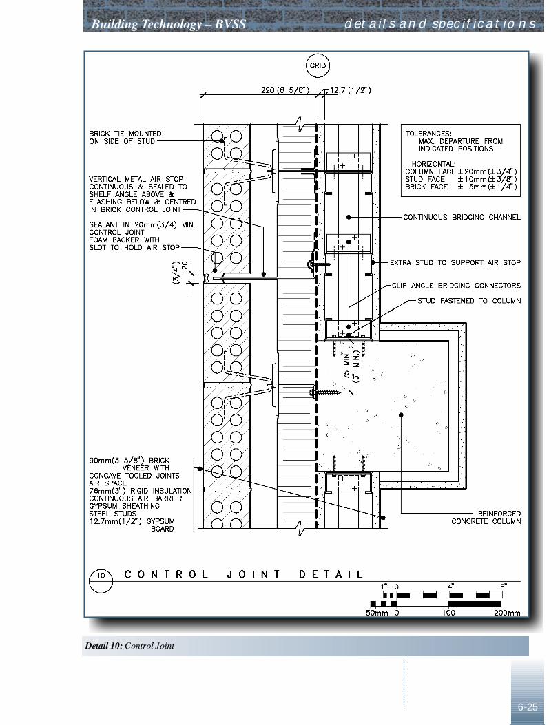
������������ � ���������
6-25
details and specifications
��������� )���� �����
DETAILS AND SPECIFICATIONS Building Technology – BVSS
6-26
SI Units Imperial Units Detail 11 - COLD SOFFIT
Warm soffits are difficult to build so thatthey are airtight. They make expensive places to put water piping in dangerof freezing. Except when there is no option, the insulation of a soffitshould be attached directly to the underside of the floor structure.
The large volume of the soffit, added to thewall cavity volume below, would be likely to prevent pressure equalizationof the cavity in the recessed wall. In this case, the dimensions of the recessprovide shelter and eliminate the need for a rain screen in the recess.Otherwise, a horizontal compartment barrier is required between the wallcavity and the soffit cavity.
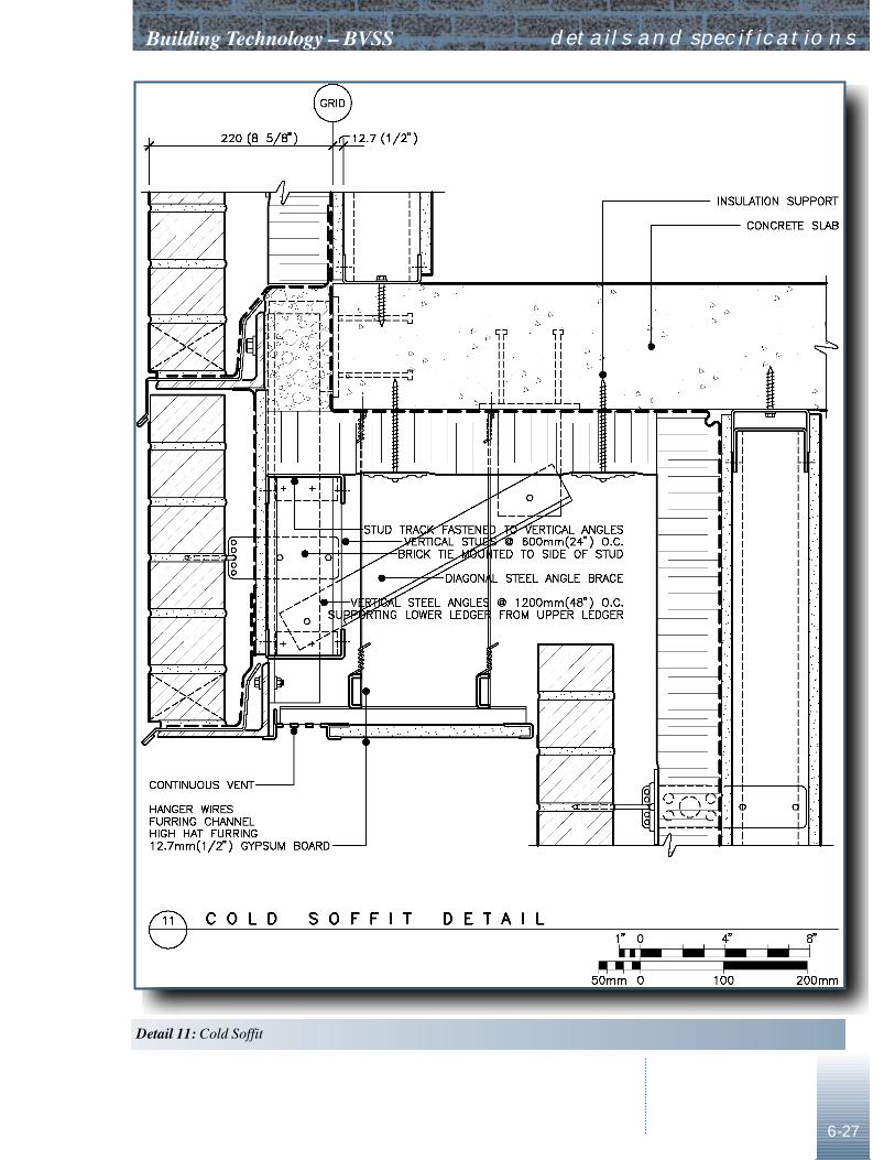
������������ � ���������
6-27
details and specifications
��������� ����������
DETAILS AND SPECIFICATIONS Building Technology – BVSS
6-28
SI Units Imperial Units Detail 12 - EXHAUST VENT
This detail should be avoided in manycases, especially in colder climates. Unless the building is horizontallycompartmented on the interior to prevent cumulative stack effect, air willexhaust on upper floors whether the fan is working or not. Centralizedexhaust with heat recovery may be a more effective solution.
This detail illustrates two useful features.The box built into the veneer provides a shelter for the vent. If the ductextends to the face of the wall, with a conventional flanged hood anddamper, then water running down the face of the wall commonly runsbehind the flange and along the top of the duct. The box also provides foradjusting alignment of the duct with the brick coursing, and the adjustablebackplate can serve as a round to rectangular adapter. The flange on theduct provides for continuity of the air barrier.
The damper location is not ideal. Somecondensation will occur in the uninsulated portion of the duct as well as onthe back of the damper, but a damper at the line of the insulation would notbe accessible for service, and a damper inside the building would make itdifficult to decide where to put a vapour barrier for the duct insulation,since the duct could be either cold or warm, depending on operation of thefan.
If the duct alignment interferes with a stud,provide a structurally framed opening.
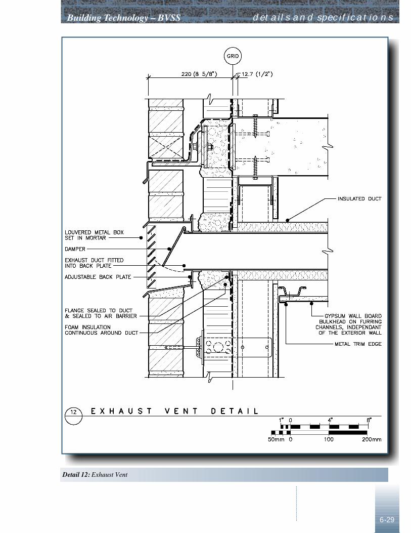
������������ � ���������
6-29
details and specifications
��������� �� ������
DETAILS AND SPECIFICATIONS Building Technology – BVSS
6-30
SI Units Detail 13 - CURTAIN WALL JAMB,Imperial Units SILL AND SLAB
The curtain wall continues past the edge ofthe slab, with an insulated backpan for the spandrel. Glass edge andspandrel pan cavities are another area where RAIN can help to evaluatepressure equalization. In many cases, for pressure equalization to occur,larger than usual vents and stiffer backpans are required.
Aluminum framing discontinuous at thefloor slabs could be located further inward, possibly with the back of thethroat in line with the air barrier. In any case, the mass of the frame needsto be kept warm, and it should be possible to remove the pressure plate andcap adjoining the brickwork without cutting sealant.
If construction sequence is a concern, amore complicated detail would allow the aluminum framing to be installedafter the brickwork, whereas this detail requires it to be installed first:provide a sheet metal angle, like a compartment seal, 25 mm (1 in.) or sofrom the side of the curtainwall, and seal the air barrier to it. Insulate thisangle, instead of the side of the aluminum framing. After installation of thebrick, install a second metal angle, formed with an S-lock pocket filledwith sealant and slid onto the edge of the first angle, and seal it to the backof the glazing rebate to complete the air barrier connection.
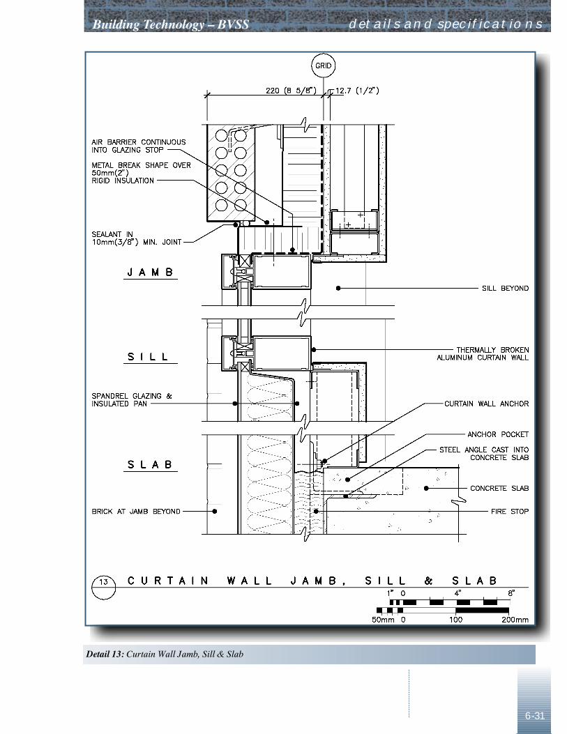
������������ � ���������
6-31
details and specifications
��������� ��� ���� ���� ������������� �
DETAILS AND SPECIFICATIONS Building Technology – BVSS
6-32
Specifications
Division 4 MasonryMasonry veneer for use with steel studs is no different from masonryveneer for other back-up systems, with the possible exception of tieselection. If the design of the steel framing is to be done by the contractor,pick ties that are known to be stiff and to interact appropriately with theframing, since the designer needs to take the ties into account but has noinfluence on their selection. CSA S304.1-94 requires each tie to bedesigned to carry 40% of the tributary load on a vertical strip of masonryone stud spacing in width, and so that deflection under a 0.45 kN (100 lbf)load does not exceed 1.0 mm (0.04 in.), unless a detailed stiffness analysisis done of the composite structure comprising the framing, ties, and veneer.The ties least likely to cause problems in service attach directly to the webof the stud, rather than to the flange or through the sheathing. They alsohave substantial interior mass and surface, and are nearly equally stiff at allpossible adjustments. Consideration should be given to strengthening thetop row of ties, however, since actual loads, based on the McMaster testsand theoretical models, can be about 50% of the tributary load.5 If the wallis designed in detail, and documented in the working drawings andspecifications, then the designer of the stud framing should design thebrickwork and ties as well.
Choice of brick and mortar for veneer aredealt with in the CMHC Best Practice Guide for Brick Veneer, ConcreteMasonry Backup6. The NMS provides appropriate master specifications.7
Division 7 Thermal and Moisture ProtectionCSC’s TEK•AID8 on air barriers provides background information andguide specifications for air barriers. The mock-up requirements, andperformance requirements for the air barrier should be correlated with theair flows that the designer expects to be tolerable, and specified. Specificmaterials and methods of application can be specified in conjunction withperformance requirements, provided that reports are available to showbidders that a prototype has been tested successfully.
Section 05410 Lateral Load-bearing Steel Stud FramingA guide specification for this section is included, both in the Appendix andon CD-ROM.
The specification can be applied moregenerally than the details. It should be useful for any building whereengineering of the steel studs is delegated to the contractor, with designand details to be delineated on shop drawings. In conjunction with theguide and the SPEC NOTES it should be self-explanatory.
5 Drysdale, Defining Better Cladding Systems.6 Hallsall and Otto + Bryden, Best Practice Guide, Building Envelope Design, Masonry
Veneer/Concrete Block Construction.7 National Master Specification, Division 4.8 CSC TEK•AID Reference 07195 - Air barriers.
Building Technology – BVSS
6-33
Section 09250 Gypsum BoardIf either interior gypsum board, or exterior gypsum sheathing supports theair barrier, it is likely that specific requirements for fastening and directionof span of the board will need to be added to most master specifications.Otherwise, specifications like the NMS should suffice.
Coordination of Specification SectionsThe sections specifying cash allowances, testing, concrete, masonry, metalfabrications, air barrier, insulation, metal flashing, and gypsum board in aproject specification are all affected by the design of the steel stud exteriorwalls.
• Describe testing and inspection required for steel studs, and provide for thecost.
• Describe testing procedures for detecting air leaks, and provide for thecost.
• Coordinate tolerances specified for masonry, concrete, and steel to ensurethat inaccuracies within the tolerances specified will never make the detailsimpossible to build, even at the extremes.
• Specify adequate fastening of insulation to avoid wind gust displacement,corrosion, and damage to the air barrier.
• Ensure that the air barrier will accommodate the ties and supports used forcladding, that it will function as flashing where required, andaccommodate movement at joints. If movement is large, butyl rubbersheets might be needed to supplement a modified bituminous air barrier,for instance.
• Specify fasteners, fastener spacing, and board orientation required forinterior drywall and gypsum sheathing.
details and specifications

DETAILS AND SPECIFICATIONS Building Technology – BVSS
6-34
Files on CD-ROM
Drawing FilesThe details included in the guide are also included in the CD-ROM as AutoCAD 9
release 10 DWG files, and as DXF files. All are provided in SI (Metric)versions at 1:5 scale with layers offering a choice of English or Frenchnotes and titles. There are also both DXF and DWG versions for users whoprefer dimensions in inches and feet, at 3"=1’0 scale. Refer to README.TXTCD-ROM for further information.
Specification FilesThe guide specification, Section 05410, is included in the CD-ROM in WP5 formatconforming to the CSC 10 Electronic Style Guide, and in several other formats,one of which should be capable of being used with almost any PC-compatibleword processor. It is provided in both English and French, in SI (Mteric) units,CSC Page Format, and refers to applicable Canadian standards, Refer toREADME.TXT on CD-ROM for further information.
9 © Autodesk.10 Construction Specifications Canada.
REFERENCES
R-1
Blomberg, Thomas. HEAT2, A Heat Transfer PC-Program. Lund, Sweden:The Department of Building Physics, Lund University, April 1991.
–––. HEAT2 (v2.53). Lund: The Department of Building Physics, LundUniversity, August 1995.
–––. HEAT3, A PC-Program for Heat Transfer in Three Dimensions. Lund:Group for Computational Building Physics, Lund University, November1995.
Brown, W.C. and Poirier, G.F. Testing of Air Barrier Systems for WoodFrame Walls (Report No. CR5505.1). Ottawa: NRC Institute for Researchin Construction (IRC), June 3, 1988.
Bumbaru, D., Jutras, R., and Patenaude, A. Air Permeance of BuildingMaterials, Summary Report (AIR-INS Inc). Ottawa: CMHC, June 17,1988.
The Canadian Sheet Steel Building Institute. Lightweight Steel FramingManual (CSSBI 50M-91). Cambridge: CSSBI, August 1988.
–––. Lightweight Steel Framing Design Manual (CSSBI 51M-91).Cambridge: CSSBI, July 1991.
–––. Guide Specification for Wind Bearing Steel Studs (CSSBI S5-90).Cambridge: CSSBI, December 1990.
Canadian Standards Association. Masonry Design for Buildings (LimitStates Design) (CAN/CSA-S304-94). Rexdale, CSA, 1994.
–––. Connectors for Masonry (CSA A370-94). Rexdale, CSA, 1994.
–––. Masonry Construction for Buildings (CSA A371-94). Rexdale, CSA,1994.
Chien, N., Feng, Y., Wang, H, and Siao, T. Wind-Tunnel Studies of PressureDistribution on Elementary Building Forms. Iowa City: The Iowa Instituteof Hydraulic Research, State University of Iowa, 1951.
Cowie, J.W. The Failure of Steel Studs (ENCON Loss Control Bulletin#89). Ottawa: ENCON Insurance Managers, September 1990.
Construction Specifications Canada. TEK•AID Reference 07195 - AirBarriers. Toronto: CSC, March 1990.
Drysdale, Robert G. Defining Better Cladding Systems - Theoretical Work.Ottawa: CMHC, July 1991.
–––, and Breton, N. Strength and Stiffness Characteristics of Steel StudBackup Walls Designed to Support Brick Veneer (McMaster University testprogram on BV/SS wall systems, Part 1). Ottawa: CMHC, March 1989.
–––, Kluge, A., and Roscoe, Peter. A Report on Water LeakageCharacteristics of Bricks and Brick Assemblages (McMaster Universitytest program on BV/SS wall systems, Part 2). Ottawa: CMHC, May 1990.
–––, and Kluge, A. Performance of Brick Veneer/Steel Stud Wall SystemsSubject to Temperature, Air Pressure and Vapour Pressure Differentials(McMaster University test program on BV/SS wall systems, Part 3).Ottawa: CMHC, May 1990.
–––, and Wilson, Michael J. Behaviour of Brick Veneer/Steel Stud TieSystems (McMaster University test program on BV/SS wall systems,Part 4). Ottawa: CMHC, March 1989.
Building Technology – BVSS
REFERENCES Building Technology – BVSS
R-2
–––, and Wilson, Michael J. Tests of Full Scale Brick Veneer/Steel StudWalls to Determine Strength and Rain Penetration Characteristics(McMaster University test program on BV/SS wall systems, Part 5).Ottawa: CMHC, July 1990.
–––, and Chidiac, S.E. “Defining Better Cladding Systems - TheoreticalWork”, Seminar on Brick Veneer Wall Systems. Ottawa: CMHC, 1989.
–––, and Suter, G.T. Exterior Wall Construction in High-Rise Buildings,Brick Veneer on Concrete Masonry or Steel Stud Wall Systems(ISBN 0-660-13759-3, DSS NH15-20/1991E). Ottawa: CMHC, 1991.
Ganguli, U., and Dalgliesh W.A. “Wind Pressures on Open Rain ScreenWalls: Place Air Canada.” ASCE Journal of Structural Engineering, Vol.114, No. 3, March, 1988. (Reprint available as IRC Paper No. 1525,NRCC 28859).
Garden, G.K., Control of Air Leakage is Important (CBD 72). Ottawa:NRC Division of Building Research (DBR), 1965.
Gulay, B.W., Stewart, C.D., Foley, G.J. Field Investigation Survey ofAirtightness, Air Movement and Indoor Air Quality in High Rise Buildings,Summary Report (Wardrop Engineering). Ottawa: CMHC, July 1993.
Halsall, R., and Otto + Bryden Architects. Best Practice Guide, BuildingEnvelope Design, Masonry Veneer/Concrete Block Construction. Ottawa:CMHC, (unpublished, work in progress).
Handegord, G.O., The Need for Improved Air Tightness in Buildings(Building Research Note 151). Ottawa: NRC DBR, 1979
Hansen, A.T., Moisture Problems in Houses (CBD 231). Ottawa: NRCDBR, 1984.
Hatzinikolas, M.A., Lee, R., and Warwaruk, J. Factors Affecting thePerformance of Metal Stud Walls used as a Backup System to MasonryVeneer. Edmonton: Prairie Masonry Research Institute, December 1987.
–––, Elwi, A.E..; and Warwaruk, J. Connecting Cavity Walls. Edmonton:Prairie Masonry Research Institute, 1991.
Hutcheon N.B. Humidity in Canadian Buildings (CBD 1). Ottawa: NRCDBR, 1960, revised 1968.
–––. Requirements for Exterior Walls (CBD 48). Ottawa NRC DBR, 1963.
–––, and Handegord, G.O. Building Science for a Cold Climate(ISBN 0-471-79763-4). Toronto: John Wiley & Sons, 1983
Keller, H. Brick Veneer/Steel Stud Wall Design and Construction Practicesin Canada: Results of a 1986 Survey. Ottawa: CMHC, 1986.
Keller, H. Field Investigation of Brick Veneer/Steel Stud Wall Systems(Suter Keller Inc). Ottawa: CMHC, 1989.
–––, Trestain T.W.J., and Maurenbrecher A.H.P.; “The Durability of SteelComponents in Brick Veneer/Steel Stud Wall Systems.” Proceedings of theSixth Conference on Building Science and Technology. Waterloo:University of Waterloo and CSCE, 1992.
Latta, J.K. Inaccuracies in Construction (CBD 171). Ottawa: NRC DBR,1975.
–––. Vapour Barriers What are They? How are they Effective? (CBD 175).Ottawa NRC DBR, 1976.
Building Technology – BVSS
R-3
REFERENCES
–––. Walls Windows and Roofs for the Canadian Climate (NRC DBRSpecial Technical Publication No. 1, NRCC 13487). Ottawa NRC DBR,1973.
McDonald, D. Structural Requirements for Air Barriers (MorrisonHershfield Report No. 30133.OR1). Ottawa: CMHC, August 13, 1991.
Morrison Hershfield Limited. A Study of the Rainscreen Concept appliedto Cladding Systems on Wood Frame Walls. Ottawa: CMHC, August 3,1990.
Oak Ridge National Laboratory, DOE. Heating 7.2 (PSR-199). Oak Ridge,TN: Radiation Shielding Information Center, Oak Ridge NationalLaboratory, February 1993.
Public Works Canada. National Master Specification. Toronto:Construction Specifications Canada, and Spencerville: Royal ArchitecturalInstitute of Canada, updated periodically.
Quirouette, R.L. The Difference Between a Vapour Barrier and an AirBarrier (Building Practice Note No. 54). Ottawa: NRC DBR, 1985.
–––. CMHC Research Project Testing of Air Barriers Construction Details(Morrison Hershfield Report No. 30132.OR/2). Ottawa: CMHC, Aug. 26,1991.
–––. CMHC Research Project Testing of Air Barriers Construction DetailsII (Morrison Hershfield Report No. 32173.03/1). Ottawa: CMHC, Mar. 31,1993.
–––, Ganguli, U., Lux, M.E., Brown, W.C., and Perreault, J.C. “An AirBarrier for the Building Envelope” Building Science Insight ’86 (NRCDBR Proceedings No. 13, NRCC 29943, ISSN 0835-653X). Ottawa: NRCDBR, January 1989.
Reginato, R., and Handegord, G. A Procedure for Estimating the MoisturePerformance of Building Envelopes. Brampton: TROW, ca. 1990.
Robinson, G., and Baker M.C. Wind-Driven Rain and Buildings (TechnicalPaper No. 445, NRCC 14792). Ottawa: NRC DBR, 1975.
Rousseau, J., Keller H., Drysdale R., and Suter, G. Seminar on BrickVeneer Wall Systems. Ottawa: CMHC/CCRB/ABEC/MBEC/OBEC, June1989.
–––, Rousseau, M.Z., Quirouette, R.L., and Handegord, G.O. “Humidity,Condenstation, and Ventilation in Houses” Building Science Insight ’83(NRC DBR Proceedings No. 7, NRCC 23293). Ottawa: NRC DBR, May1984.
Shaw, C.Y., and Tamara, G.T. “Studies on Exterior Wall Air Tightness andAir Infiltration of Tall Buildings” ASHRAE Transactions, Vol. 82, Part I,1976.
Trestain, T.W.J. The Success of Steel Studs (ENCON Loss Control Bulletin#90). Ottawa: ENCON Insurance Managers, June 1991.
TROW Inc. Criteria for The Air Leakage Characteristics of BuildingEnvelopes (Project No. B-03499-A). Ottawa: CMHC, December 1989.
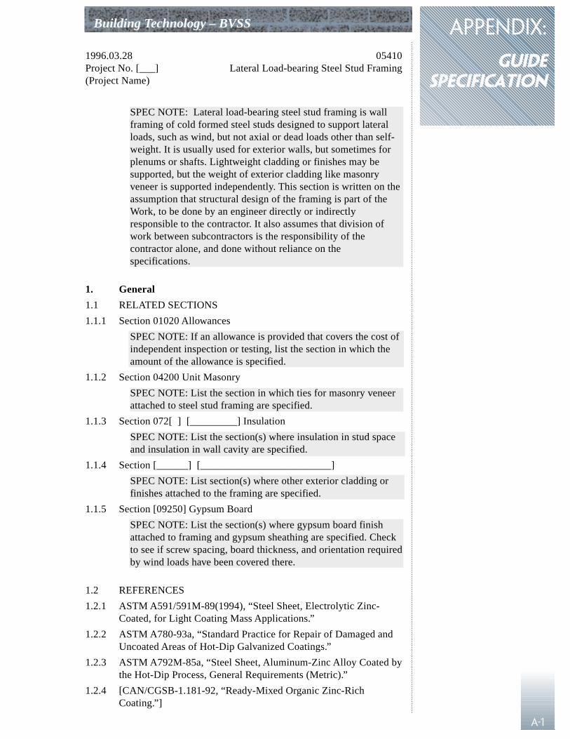
APPENDIX:
gUIDESPECIFICATION
A-1
Building Technology – BVSS
1996.03.28 05410Project No. [___] Lateral Load-bearing Steel Stud Framing(Project Name)
SPEC NOTE: Lateral load-bearing steel stud framing is wallframing of cold formed steel studs designed to support lateralloads, such as wind, but not axial or dead loads other than self-weight. It is usually used for exterior walls, but sometimes forplenums or shafts. Lightweight cladding or finishes may besupported, but the weight of exterior cladding like masonryveneer is supported independently. This section is written on theassumption that structural design of the framing is part of theWork, to be done by an engineer directly or indirectlyresponsible to the contractor. It also assumes that division ofwork between subcontractors is the responsibility of thecontractor alone, and done without reliance on thespecifications.
1. General
1.1 RELATED SECTIONS
1.1.1 Section 01020 Allowances
SPEC NOTE: If an allowance is provided that covers the cost ofindependent inspection or testing, list the section in which theamount of the allowance is specified.
1.1.2 Section 04200 Unit Masonry
SPEC NOTE: List the section in which ties for masonry veneerattached to steel stud framing are specified.
1.1.3 Section 072[ ] [_________] Insulation
SPEC NOTE: List the section(s) where insulation in stud spaceand insulation in wall cavity are specified.
1.1.4 Section [______] [_________________________]
SPEC NOTE: List section(s) where other exterior cladding orfinishes attached to the framing are specified.
1.1.5 Section [09250] Gypsum Board
SPEC NOTE: List the section(s) where gypsum board finishattached to framing and gypsum sheathing are specified. Checkto see if screw spacing, board thickness, and orientation requiredby wind loads have been covered there.
1.2 REFERENCES
1.2.1 ASTM A591/591M-89(1994), “Steel Sheet, Electrolytic Zinc-Coated, for Light Coating Mass Applications.”
1.2.2 ASTM A780-93a, “Standard Practice for Repair of Damaged andUncoated Areas of Hot-Dip Galvanized Coatings.”
1.2.3 ASTM A792M-85a, “Steel Sheet, Aluminum-Zinc Alloy Coated bythe Hot-Dip Process, General Requirements (Metric).”
1.2.4 [CAN/CGSB-1.181-92, “Ready-Mixed Organic Zinc-RichCoating.”]
appendix: guide specification Building Technology – BVSS
A-2
1.2.5 CAN/CGSB-7.1-M86, “Cold Formed Steel Framing Components.”
1.2.6 [CSA W59-M1989, “Welded Steel Construction (Metal ArcWelding).”]
1.2.7 [CSA W47.1-92, “Certification of Companies for Fusion Weldingof Steel Structures.”]
1.2.8 CAN/CSA-S136-94, “Cold Formed Steel Structural Members.”
1.2.9 [CAN/ULC-S101-M89, “Standard Methods of Fire EnduranceTests of Building Construction and Materials.”]
1.2.10 [ANSI/AWS D1.3-89, “Structural Welding Code - Sheet Steel.”]
SPEC NOTE: List standards used as references elsewhere in thissection by designation, date or edition, and title.
1.3 QUALITY ASSURANCE
1.3.1 Employ a professional engineer registered in the place of the workto design metal stud systems; to prepare, seal, and sign all shopdrawings; and to perform field reviews.
1.3.2 [Do welding in accordance with [CSA S136 and CSA W59] [for0.70 mm and thicker material] [and][/or] [ANSI/AWS D1.3]].
SPEC NOTE: Under S136, most welds involving materials lessthan 0.70 mm are considered to have negligible structural value.D1.3 covers welding of thinner material. Review the standardsbefore deciding to use welded connections.
1.3.3 [Companies engaged in welding: certified by the CanadianWelding Bureau to CSA W47.1, with welding procedures approvedand welders qualified for the base material types and thicknessesthat are to be welded.]
SPEC NOTE: Welding of steel studs requires experience andproper equipment. Verify that both are available in the localityof the project. Welded areas exposed to moisture are susceptibleto rusting, unless properly prepared and touched-up with zinc-rich coating. Preparation sufficient to permit good metal-to-metal contact between the particles of zinc in the paintand the steel is necessary for effective protection. Corrosionprotection of welds and availability of qualified welders may bedisadvantages, but welded connections have the advantage ofbeing much stronger and less flexible than mechanicalconnections.
1.4 DESIGN CRITERIA
1.4.1 Calculate structural properties in accordance with CAN/CSA-S136, limit states design principles using factored loadsand resistances.
1.4.2 Calculate loads and load factors in accordance with the [NationalBuilding Code] [_______________________].
1.4.3 Determine resistances and resistance factors in accordance with the[National Building Code] [_______________________] andCSA-S136.
Building Technology – BVSS
A-3
APPENDIX: GUIDE SPECIFICATION
1.4.4 Conform to the requirements of fire rated assemblies [indicated][which have been tested in accordance with CAN/ULC-S101-Mand provide a fire resistance rating of [____________]].
1.4.5 Select studs which will deflect under specified lateral loads notmore than [L/240] [L/360] for wall studs supporting [metalcladding] [stucco] and [L/720] [_____] for wall studs supportingmasonry veneer cladding. Limit free play and movement inconnections perpendicular to the plane of the framing to [0.5] [1][__] mm relative to the building structure.
SPEC NOTE: More needs to be considered than stiffness of thestuds. The deflection experienced by the cladding depends notonly on bending of the studs, but also on take-up of free playand lateral displacement in connections under load. Localizeddeformations can also contribute where the cladding isconnected to the studs. CSA S304.1 requires that thecombination of all these effects be less than L/600, if thestiffness (EI) of the backup wall is less than 2.5 times that ofuncracked veneer. This requirement is deemed to be met if thedeflection of the framing is not more than L/720, and if half ofthe free play in the ties plus the deflection resulting from a loadof 0.45 kN does not exceed 1.0 mm. These deflections will noteliminate cracking, but rain screen design of the wall shouldlimit resulting water penetration to acceptable levels. Designattention and money will be better expended on reinforcementaround openings and detailing, rather than on selection of stifferstuds. Where comprehensive structural investigation of theinteraction between wall framing, connections, ties, openingsizes and locations, and masonry veneer is done, otherdeflection limits may be appropriate. Other claddings, whileable to accommodate more bending than masonry veneer, maybe less able to accommodate displacement at connections,depending on details. Brick veneer tends to be supported at thebottom by the shelf angle, and to rotate without distress whenthe top connection is flexible. Regardless of cladding, L/360 isthe least restrictive limit allowable if there is gypsum boardcladding or interior finish.
1.4.6 Space wall studs at [300] [400] [_____] mm maximum intervals[in back to back pairs].
SPEC NOTE: If stud spacing required is less than 300 mm,placing studs back to back may be more efficient structurallyand may permit elimination of bracing. Specify stud spacingrequired to support cladding and finishes.
1.4.7 Stud depth is shown on the drawings. Adjust stud materialthickness, stud spacing, or both as required by design criteria. Usegreater or lesser stud depths only if approved by the [Engineer][Consultant].
1.4.8 Design metal stud systems and attachments to accommodate thefull range of tolerances permitted in adjoining materials.
SPEC NOTE: Coordinate tolerances specified for adjoiningmaterials with details on drawings to be sure the details areworkable over the full range of possible positions of eachelement. Specify tighter tolerances if needed.
1.4.9 Design stud end connections to accommodate structuraldeflections, frame shortening, and vertical tolerances permitted instructure such that studs are not loaded axially. [Provide for[____] mm differential in floor to head height for all effectscombined.]
SPEC NOTE: Consult the designer of the building structure todetermine possible structural movement during and afterconstruction, and add an additional amount for tolerancedepending on tolerances allowed in the structure. If studs are tobe pre-cut, consider how accurately this can be done. Lessallowance may be required for tolerance than the sum of theallowable extremes, since the probability of 2 or more worstcases occurring at the same place is low.
1.4.10 Take into account local loadings due to anchorage of cladding andinterior wall mounted fixtures where shown.
1.4.11 Design bridging to prevent member rotation and membertranslation perpendicular to the minor axis for lateral load bearingstuds. Provide for secondary stress effects due to torsion betweenlines of bridging. [Sheathing may be used to help restrain memberrotation and translation perpendicular to the minor axis for windbearing studs] [Do not rely on cladding, sheathing, or insulationfor lateral bracing]. Provide metal bridging at [1500 mmo.c.][1220 mm o.c. for brick veneer] maximum. Use closer spacingif required by structural design.
SPEC NOTE: Allow use of gypsum sheathing as bracing only indry conditions. Standard fastening may not be adequate ifgypsum sheathing is used as bracing; coordinate fasteningrequirements in Section [09250] to ensure that cyclic loadingwill not render the sheathing ineffective as bracing.
1.5 SUBMITTALS
1.5.1 Make submittals in accordance with [Section [01340] [01300]][Division 1].
SPEC NOTE: Refer to Section 01340 for Federal Governmentprojects. Otherwise, refer to Section 01300 or to Division 1, oromit this paragraph.
1.5.2 Submit shop drawings indicating design loads, member sizes andspacings, materials, thicknesses exclusive of coatings, sectionproperties, coating specifications, connection and bridging details,types, sizes, and spacing of fasteners [or welds], and tolerances.Indicate locations, dimensions, openings, tolerances, andrequirements for coordination of adjoining work.
1.5.3 [Show nominal weld leg sizes for materials less than 3 mm thick.For such welds the throats shall not be less than the thickness ofthe thinnest connected part.]
appendix: guide specification Building Technology – BVSS
A-4
Building Technology – BVSS
A-5
APPENDIX: GUIDE SPECIFICATION
1.5.4 Show coordination with [masonry connectors] [exterior cladding],and other attachments including windows, door frames, louvres,woodwork, plumbing fixtures, and electrical fixtures and panels.
SPEC NOTE: This is an onerous task. The size and complexityof the job should be considered, and this requirement simplifiedaccordingly. The more times a particular detail will be repeated,the more important it is to work it out carefully in advance. But,for smaller projects, shop drawings should be considerablysimplified.
1.5.5 Submit two (2) certified copies of mill reports covering chemicaland mechanical properties, and coating designation of steel used inthe work.
1.5.6 Submit product data for mechanical fasteners, indicating sizes,load capacities, and type of corrosion protection.
1.5.7 Submit samples of all framing components and fasteners ifrequested.
1.5.8 Do not construct work until review of submittals [other than fieldreview reports] is completed.
1.5.9 Submit two (2) copies of field review reports.
2. Products
2.1 MATERIALS
2.1.1 Steel sheet: to CAN/CSA-S136, with [electrolytic Zinc] [hot-dipZinc (galvanized)] [Aluminum-Zinc] metallic coating.
SPEC NOTE: For federal projects, the NMS contains additionalrequirements which are otherwise adequately covered by S136.
2.1.2 Electrolytic Zinc coating: to ASTM A591/591M, Class [__] [C]
SPEC NOTE: Class A coating has no minimum thickness, ClassB requires 24 g/m² of Zinc, Class C requires 48 g/m² of Zinc.None are suitable for exterior exposure. Class C isrecommended for interior framing. Use hot-dip galvanizedframing for exterior walls.
2.1.3 Hot-dip Zinc (galvanized) coating: to ASTM A653M, designation[________] [ZF75] [Z180] [Z275] [Z350].
SPEC NOTE: Common coating weight designations underA653M are listed above in order of increasing thickness; checkwith manufacturers for available coatings. ZF75 is used forinterior framing. Z180 is often used for exterior walls, but notrecommended unless air barrier is outside, with no insulation instud space. Z275 (the metric equivalent of G90) is the currentmost commonly available material. Additional possibledesignations are listed below. Coatings thicker than Z350 aredifficult to fabricate into cold-formed framing. As zinc thicknessand yield strength increase, larger minimum bend radii arerequired. Coatings thicker than Z275 are not available in lessthan 20-tonne coils.
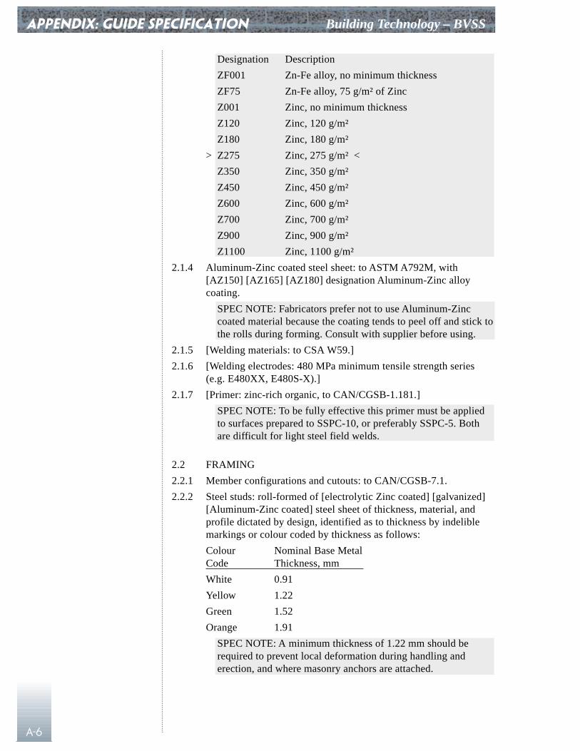
appendix: guide specification Building Technology – BVSS
A-6
Designation Description
ZF001 Zn-Fe alloy, no minimum thickness
ZF75 Zn-Fe alloy, 75 g/m² of Zinc
Z001 Zinc, no minimum thickness
Z120 Zinc, 120 g/m²
Z180 Zinc, 180 g/m²
> Z275 Zinc, 275 g/m² <
Z350 Zinc, 350 g/m²
Z450 Zinc, 450 g/m²
Z600 Zinc, 600 g/m²
Z700 Zinc, 700 g/m²
Z900 Zinc, 900 g/m²
Z1100 Zinc, 1100 g/m²
2.1.4 Aluminum-Zinc coated steel sheet: to ASTM A792M, with[AZ150] [AZ165] [AZ180] designation Aluminum-Zinc alloycoating.
SPEC NOTE: Fabricators prefer not to use Aluminum-Zinccoated material because the coating tends to peel off and stick tothe rolls during forming. Consult with supplier before using.
2.1.5 [Welding materials: to CSA W59.]
2.1.6 [Welding electrodes: 480 MPa minimum tensile strength series(e.g. E480XX, E480S-X).]
2.1.7 [Primer: zinc-rich organic, to CAN/CGSB-1.181.]
SPEC NOTE: To be fully effective this primer must be appliedto surfaces prepared to SSPC-10, or preferably SSPC-5. Bothare difficult for light steel field welds.
2.2 FRAMING
2.2.1 Member configurations and cutouts: to CAN/CGSB-7.1.
2.2.2 Steel studs: roll-formed of [electrolytic Zinc coated] [galvanized][Aluminum-Zinc coated] steel sheet of thickness, material, andprofile dictated by design, identified as to thickness by indeliblemarkings or colour coded by thickness as follows:
Colour Nominal Base MetalCode Thickness, mm
White 0.91
Yellow 1.22
Green 1.52
Orange 1.91
SPEC NOTE: A minimum thickness of 1.22 mm should berequired to prevent local deformation during handling anderection, and where masonry anchors are attached.
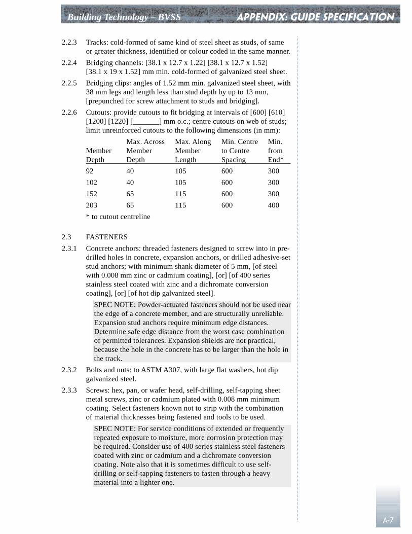
Building Technology – BVSS
A-7
APPENDIX: GUIDE SPECIFICATION
2.2.3 Tracks: cold-formed of same kind of steel sheet as studs, of sameor greater thickness, identified or colour coded in the same manner.
2.2.4 Bridging channels: [38.1 x 12.7 x 1.22] [38.1 x 12.7 x 1.52][38.1 x 19 x 1.52] mm min. cold-formed of galvanized steel sheet.
2.2.5 Bridging clips: angles of 1.52 mm min. galvanized steel sheet, with38 mm legs and length less than stud depth by up to 13 mm,[prepunched for screw attachment to studs and bridging].
2.2.6 Cutouts: provide cutouts to fit bridging at intervals of [600] [610][1200] [1220] [_______] mm o.c.; centre cutouts on web of studs;limit unreinforced cutouts to the following dimensions (in mm):
Max. Across Max. Along Min. Centre Min.Member Member Member to Centre from Depth Depth Length Spacing End*
92 40 105 600 300
102 40 105 600 300
152 65 115 600 300
203 65 115 600 400
* to cutout centreline
2.3 FASTENERS
2.3.1 Concrete anchors: threaded fasteners designed to screw into in pre-drilled holes in concrete, expansion anchors, or drilled adhesive-setstud anchors; with minimum shank diameter of 5 mm, [of steelwith 0.008 mm zinc or cadmium coating], [or] [of 400 seriesstainless steel coated with zinc and a dichromate conversioncoating], [or] [of hot dip galvanized steel].
SPEC NOTE: Powder-actuated fasteners should not be used nearthe edge of a concrete member, and are structurally unreliable.Expansion stud anchors require minimum edge distances.Determine safe edge distance from the worst case combinationof permitted tolerances. Expansion shields are not practical,because the hole in the concrete has to be larger than the hole inthe track.
2.3.2 Bolts and nuts: to ASTM A307, with large flat washers, hot dipgalvanized steel.
2.3.3 Screws: hex, pan, or wafer head, self-drilling, self-tapping sheetmetal screws, zinc or cadmium plated with 0.008 mm minimumcoating. Select fasteners known not to strip with the combinationof material thicknesses being fastened and tools to be used.
SPEC NOTE: For service conditions of extended or frequentlyrepeated exposure to moisture, more corrosion protection maybe required. Consider use of 400 series stainless steel fastenerscoated with zinc or cadmium and a dichromate conversioncoating. Note also that it is sometimes difficult to use self-drilling or self-tapping fasteners to fasten through a heavymaterial into a lighter one.
appendix: guide specification Building Technology – BVSS
A-8
3. Execution
3.1 WORKMANSHIP
3.1.1 [Fabricate and erect metal stud systems in accordance withreviewed shop drawings.] Where conditions other than minordimensional changes are encountered which are not covered by theshop drawings, obtain direction from the engineer responsible forsteel stud design.
SPEC NOTE: For non-federal specifications the first sentencecan be omitted if it serves only to repeat requirements containedin the front end.
3.1.2 Cut members using saw or shears.
3.2 Erection
3.2.1 Construct framing piece by piece (stick-built), or by fabricatinginto panels either on or off site.
3.2.2 Erect framing true and plumb within specified tolerances. Takeactual built dimensions of previously constructed work intoaccount and accommodate them by adjusting position of framing.Make all field measurements necessary to ensure fit of allmembers.
3.2.3 Provide temporary bracing, if required for framing to sustain loadsapplied during erection and subsequent construction.
3.2.4 Anchor tracks securely to structure at [______] [800 mm] o.c.maximum. Place one additional anchor within [150][100] mm ofeach end of each piece of track, and additionally as required bystructural design.
SPEC NOTE: In some cases 800 mm is too far apart. Determineanchor size and spacing from the load carried by each anchor inrelation to anchor capacity and the maximum acceptabledeflection of track between anchors.
3.2.5 Erect studs plumb and in alignment, and attach both flanges to legsof top and bottom tracks with one screw, No. 8 minimum diameter,at each connection (4 per stud). Do not splice studs.
3.2.6 Reinforce cutouts which occur within 300 mm of the end of a stud.[Align stud cutouts horizontally.] Do not allow additional cutoutsto be made in the field, except as approved by the engineerresponsible for preparation of shop drawings.
SPEC NOTE: Stud cutouts near end connections cansubstantially reduce the load carrying capacity of the wholestud. If studs are only available with cutouts near the ends,reinforcements should be designed and appear on the shopdrawings. Cutouts need to be aligned both for through-the-cutout bridging and for service installations.
3.2.7 [Use nested inner and outer track for attachment to overheadstructures.] [Use flexible stud clips to attach studs to overheadstructures.] [Use sliding stud clips to attach studs to overheadstructures.] Leave a minimum gap of [12 mm] [______] to
Building Technology – BVSS
A-9
APPENDIX: GUIDE SPECIFICATION
accommodate structural movement. Design end connections formaximum take-up of play plus lateral deflection under full designload of [_____][1.0] mm at bottom connection and [______] mmat top connection.
3.2.8 [Install additional studs at not more than 50 mm from abuttingwalls, openings, terminations against other materials, and on eachside at corners.]
SPEC NOTE: This requirement is common in currentspecifications and appropriate for interior walls where noengineering is done. It is not necessary if these conditions areconsidered by the engineer responsible for the design.
3.2.9 Frame all openings in stud walls, except openings less than[100 mm] in any dimension, and provide framing at points ofattachment of wall mounted fixtures to adequately carry loads byusing additional framing members and bracing as requiredstructurally.
SPEC NOTE: Review sizes of openings to ensure that loads onwindows, doors, and other closures are adequately supported.The shop drawings should show additional support for wideropenings (usually 3 stud or more spacings). For large openingsadditional steel stud framing may not be practical. In such casesdetail separate support systems (hot rolled steel framing, forinstance) in the contract documents.
3.2.10 Brace steel studs with [horizontal bridging channels through studcutouts] [flat strap bridging] at maximum vertical centres of[1500 mm] [1220 mm for brick veneer]. [Fasten horizontalbridging channels to each stud with bridging clips using four (4)No. 8 min. diameter screws [or by welding].
SPEC NOTE: Include an isometric detail of this connection inthe contract documents. Both the strength and stiffness of steelstud framing depend on this connection.
3.2.11 Install bridging in longest practical lengths. Where splices arerequired, make them more than one stud space long, with each endfastened at a stud, [or reinforce splices with inverted channelbridging pieces 300 mm long, centred on the joint, and fastened atends (4 screws or welds, 1 at each end of reinforcement, 1 at end ofeach spliced piece)].
3.2.12 Coordinate erection of studs with installation of service lines.
3.2.13 Use screws long enough to penetrate beyond joined materials bymore than three (3) exposed threads. Use wafer-head fasteners [orwelds] where panel products will be installed against theattachment.
3.2.14 Use screws with drilling and holding capabilities recommended bythe manufacturer for the materials being fastened. Select differentscrews if initial selection fails to drill effectively, or tends to stripout.
3.2.15 Repair damaged zinc coating [and all welds] using zinc-rich primerin accordance with ASTM A780.
appendix: guide specification Building Technology – BVSS
A-10
3.3 ERECTION TOLERANCES
3.3.1 Plumb: 1/500 of member length maximum.
3.3.2 Straightness (camber and sweep): 1/1000 of member length,maximum. Replace members with local buckling or bends.
3.3.3 Spacing: not more than 3 mm from design spacing, non-cumulative.
3.3.4 Location: within 10 mm of indicated alignment, and within 5 mmwhere alignment of structure permits.
3.3.5 Gap between end of stud and web of track (when connected):4 mm maximum.
3.3.6 Alignment of adjoining or abutting members in the same plane,where supporting continuous cladding or sheathing: 1 mmmaximum.
SPEC NOTE: These tolerances have been in masterspecifications for several years. They may be unrealistically andneedlessly restrictive.
3.4 FIELD QUALITY CONTROL
3.4.1 The engineer responsible for design of the metal stud system, andpreparation of the shop drawings, shall review the work in progressat the site regularly during construction and submit field reports tothe [Engineer] [Consultant] for each visit.
3.4.2 [These field reviews shall include review of mill test reports,welded connections, member sizes and material thickness, coatingthickness, screwed connections, erection tolerances, and all fieldcutting, including cutting and patching for other trades.]
SPEC NOTE: Use this paragraph for projects where independentinspection is deemed unwarranted.
3.4.3 Additional inspection and testing of materials and workmanshipshall be carried out by an independent inspection agency appointedby the [Consultant] [Engineer]. It will include:
1. checking that mill test reports are properly correlated tomaterials;
2. sampling fabrication and erection procedures for generalconformity to shop drawing and contract requirements;
3. [checking that welding conforms to shop drawings,specification, and specified standards;]
4. checking fabricated shapes and profiles of members;5. [checking samples of joint preparation and fit-up of welded
connections;]6. [visual inspection of all welded connections;]7. sample checking of [screwed and bolted joints, and]
anchorages to structure;8. sample checking that tolerances are not exceeded during fit-up
or erection;9. general inspection of field cutting and fitting to accommodate
other parts of the work; and
Building Technology – BVSS
A-11
APPENDIX: GUIDE SPECIFICATION
10. submission of reports to the [Consultant] [Engineer], theengineer responsible for preparation of the shop drawings, andthe Contractor, covering the work inspected and details of anydeficiencies discovered.
SPEC NOTE: Check for the following requirements usuallycovered in the general conditions or general requirements:Contractor must provide access and cooperate with inspection;inspection does not relieve him of responsibility, nor can he relyon timely discovery and reporting; defective materials andworkmanship can be ordered removed, even if contractor has todestroy and rebuild other work as a result; and contractor paysfor additional inspection or testing deemed necessary to revealfull extent of discovered defects.
3.4.4 The cost of field reviews is included in the contract price. The costof inspection is included in [the cash allowance for testing][____________________].
End of Section