B70.ITRON_08
42
JiTRON Compact micro- processor controllers B 70.2040 Operating Instructions 07.05/00357918 Type 702042 Type 702044 Type 702041 Type 702043 Type 702040
Transcript of B70.ITRON_08

JiT
RO
NC
omp
act
mic
ro-
pro
cess
or c
ontr
olle
rs
B 7
0.20
40O
per
atin
gIn
stru
ctio
ns07
.05/
0035
7918
Typ
e 70
2042
Typ
e 70
2044
Typ
e 70
2041
Typ
e 70
2043
Typ
e 70
2040
Ple
ase
read
the
se O
per
atin
g In
stru
ctio
ns c
aref
ully
bef
ore
star
ting
up t
he in
stru
men
t. K
eep
thes
e op
erat
ing
inst
ruct
ions
in a
pla
ce w
hich
is a
t al
l tim
es a
cces
sib
le t
o al
l use
rs.
Ple
ase
assi
st u
s to
imp
rove
the
se o
per
atin
g in
stru
ctio
ns w
here
nec
essa
ry. Y
our
sugg
estio
ns w
ill b
em
ost
wel
com
e.
Pho
ne
in G
erm
any
(066
1) 6
003-
727
from
ab
road
(+49
) 661
600
3-0
Fax
in G
erm
any
(066
1) 6
003-
508
abro
ad(+
49) 6
61 6
003-
607
All
nece
ssar
y se
ttin
gs a
re d
escr
ibed
in t
hese
op
erat
ing
inst
ruct
ions
. How
ever
, if a
ny d
iffic
ul-
ties
shou
ld s
till a
rise
dur
ing
star
t-up
, yo
u ar
e as
ked
not
to
carr
y ou
t an
y un
auth
oriz
ed m
a-ni
pul
atio
ns o
n th
e un
it. Y
ou c
ould
end
ange
r yo
u rig
hts
und
er t
he i
nstr
umen
t w
arra
nty!
Ple
ase
cont
act
the
near
est
sub
sid
iary
or
the
mai
n fa
ctor
y in
suc
h a
case
.
EW
hen
retu
rnin
g ch
assi
s, a
ssem
blie
s or
com
pon
ents
, the
reg
ulat
ions
of E
N 1
00 0
15 “
Pro
tec-
tion
of e
lect
rost
atic
ally
sen
sitiv
e co
mp
onen
ts”
mus
t b
e ob
serv
ed.
Use
onl
y th
e ap
pro
pria
teE
SD
pac
kagi
ng fo
r tr
ansp
ort.
Ple
ase
note
that
we
cann
ot a
ccep
t any
liab
ility
for
dam
age
caus
ed b
y E
SD
(ele
ctro
stat
ic d
is-
char
ge).
ContentsC
ont
ents
1 Id
enti
fyin
g t
he in
stru
men
t ve
rsio
n .
. . .
. . .
. . .
. . .
. . .
. . .
. . .
. . .
. . .
. . .
. . .
. . .
. . .
. . .
42
Inst
alla
tio
n . .
. . .
. . .
. . .
. . .
. . .
. . .
. . .
. . .
. . .
. . .
. . .
. . .
. . .
. . .
. . .
. . .
. . .
. . .
. . .
. . .
.6
3 E
lect
rica
l co
nnec
tio
n . .
. . .
. . .
. . .
. . .
. . .
. . .
. . .
. . .
. . .
. . .
. . .
. . .
. . .
. . .
. . .
. . .
. . .
.7
4 O
per
atio
n .
. . .
. . .
. . .
. . .
. . .
. . .
. . .
. . .
. . .
. . .
. . .
. . .
. . .
. . .
. . .
. . .
. . .
. . .
. . .
. . .
.12
4.1
Dis
pla
ys a
nd k
eys
. . .
. . .
. . .
. . .
. . .
. . .
. . .
. . .
. . .
. . .
. . .
. . .
. . .
. . .
. . .
. . .
. . .
.12
4.2
Prin
cip
le o
f op
erat
ion
. . .
. . .
. . .
. . .
. . .
. . .
. . .
. . .
. . .
. . .
. . .
. . .
. . .
. . .
. . .
. . .
. .13
4.3
Op
erat
ion
of t
he t
imer
func
tion
. . .
. . .
. . .
. . .
. . .
. . .
. . .
. . .
. . .
. . .
. . .
. . .
. . .
. . .
155
Func
tio
ns .
. . .
. . .
. . .
. . .
. . .
. . .
. . .
. . .
. . .
. . .
. . .
. . .
. . .
. . .
. . .
. . .
. . .
. . .
. . .
. . .
. .16
5.1
Pro
cess
val
ue in
put
. .
. . .
. . .
. . .
. . .
. . .
. . .
. . .
. . .
. . .
. . .
. . .
. . .
. . .
. . .
. . .
. . .
.17
5.2
Logi
c in
put
. .
. . .
. . .
. . .
. . .
. . .
. . .
. . .
. . .
. . .
. . .
. . .
. . .
. . .
. . .
. . .
. . .
. . .
. . .
. .18
5.3
Con
trol
ler
. . .
. . .
. . .
. . .
. . .
. . .
. . .
. . .
. . .
. . .
. . .
. . .
. . .
. . .
. . .
. . .
. . .
. . .
. . .
. .19
5.4
Lim
it co
mp
arat
or (a
larm
con
tact
) . .
. . .
. . .
. . .
. . .
. . .
. . .
. . .
. . .
. . .
. . .
. . .
. . .
. . .
215.
5 R
amp
func
tion
. . .
. . .
. . .
. . .
. . .
. . .
. . .
. . .
. . .
. . .
. . .
. . .
. . .
. . .
. . .
. . .
. . .
. . .
.22
5.6
Sel
f-op
timiz
atio
n .
. . .
. . .
. . .
. . .
. . .
. . .
. . .
. . .
. . .
. . .
. . .
. . .
. . .
. . .
. . .
. . .
. . .
.23
5.7
Leve
l inh
ibit
via
cod
e . .
. . .
. . .
. . .
. . .
. . .
. . .
. . .
. . .
. . .
. . .
. . .
. . .
. . .
. . .
. . .
. . .
245.
8 Ti
mer
func
tion
(ext
ra c
ode)
. .
. . .
. . .
. . .
. . .
. . .
. . .
. . .
. . .
. . .
. . .
. . .
. . .
. . .
. . .
.25
6 C
onf
igur
atio
n an
d p
aram
eter
tab
les
. . .
. . .
. . .
. . .
. . .
. . .
. . .
. . .
. . .
. . .
. . .
. . .
. . .
.31
7 A
larm
mes
sag
es .
. . .
. . .
. . .
. . .
. . .
. . .
. . .
. . .
. . .
. . .
. . .
. . .
. . .
. . .
. . .
. . .
. . .
. . .
. .3
78
Tec
hnic
al d
ata
. . .
. . .
. . .
. . .
. . .
. . .
. . .
. . .
. . .
. . .
. . .
. . .
. . .
. . .
. . .
. . .
. . .
. . .
. . .
.39

1 Identifying the instrument version 4
1 Id
enti
fyin
g t
he in
stru
men
t ve
rsio
n
1. s
ingl
e-se
tpoi
nt c
ontr
olle
r w
ith li
mit
com
par
ator
, see
fac
tory
set
tings
und
er c
onfig
urat
ion
and
par
amet
er le
vel
2. s
ee c
usto
mer
’s o
rder
ing
text
or
sett
ings
und
er c
onfig
urat
ion
and
par
amet
er le
vel
(1)
(2)
(3)
(4)
(5)
(6)
7020
../
..–
...
–..
.–
../
...
,...
(1)
Bas
ic t
ype
(bez
el in
mm
)40
=48
x24
, 41
= 4
8x
48,
42 =
48
x96
(por
trai
t), 4
3 =
96
x48
(lan
dsc
ape)
, 44
= 9
6x
96
(2)
Bas
ic t
ype
exte
nsio
n88
=99
=co
ntro
ller
typ
e co
nfig
urab
le1
cont
rolle
r ty
pe
conf
igur
ed t
o cu
stom
er s
pec
ifica
tion2
(3)
Inp
uts
888
=99
9 =
inp
uts
conf
igur
able
1
inp
uts
conf
igur
ed t
o cu
stom
er s
pec
ifica
tion2
(4)
Out
put
s00
0 =
Sta
ndar
dTy
pe
7020
40/4
1Ty
pe
7020
42/4
3/44
Out
put
1re
lay
(n.o
. mak
e)re
lay
(n.o
. mak
e)
Out
put
2lo
gic
0/5
V, o
ptio
nally
conf
igur
able
als
logi
c in
put
logi
c 0/
5V
Out
put
3(n
ot a
vaila
ble
)re
lay
(n.o
. mak
e)
Op
tio
nsTy
pe
7020
40/4
1Ty
pe
7020
42/4
3/44
113
=O
utp
ut 2
(out
put
s 1+
3 as
for
Sta
ndar
d)
logi
c 0/
12V,
op
tiona
llyco
nfig
urab
le a
ls lo
gic
inp
utlo
gic
0/12
V
101
=O
utp
ut 2
(out
put
1 a
s fo
r S
tand
ard
)re
lay
(n.o
. mak
e)(lo
gic
inp
ut is
alw
ays
avai
lab
le)
not
pos
sib
le
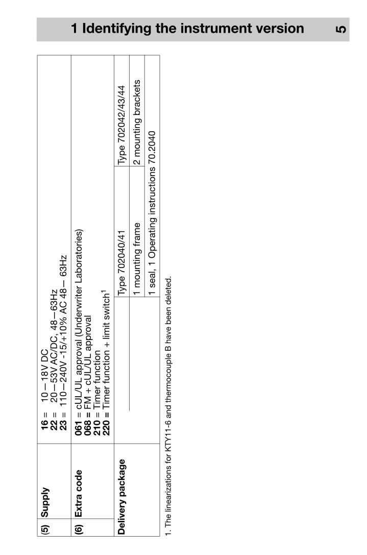
1 Identifying the instrument version 5
1. T
he li
near
izat
ions
for
KTY
11-6
and
the
rmoc
oup
le B
hav
e b
een
del
eted
.
(5)
Sup
ply
16 =
22 =
23 =
10—
18V
DC
20—
53V
AC
/DC
, 48
—63
Hz
110
—24
0V -
15/+
10%
AC
48—
63H
z
(6)
Ext
ra c
od
e06
1 =
068
= 2
10 =
220
=
cUL/
UL
app
rova
l (U
nder
writ
er L
abor
ator
ies)
FM +
cU
L/U
L ap
pro
val
Tim
er fu
nctio
nTi
mer
func
tion
+ li
mit
switc
h1
Del
iver
y p
acka
ge
Typ
e 70
2040
/41
Typ
e 70
2042
/43/
44
1 m
ount
ing
fram
e2
mou
ntin
g b
rack
ets
1 se
al, 1
Op
erat
ing
inst
ruct
ions
70.
2040

2 Installation 6
2 In
stal
lati
on
Typ
e (b
ezel
)P
anel
cut
-out
(WxH
) in
mm
Ed
ge-
to-e
dg
e-m
oun
ting
(min
imum
sp
acin
gs o
f pan
el c
ut-o
uts)
hori
zont
alve
rtic
al70
2040
(48
mm
x 2
4mm
)45
+0.
6 x
22.2
+0.
3>
8m
m>
8m
m70
2041
(48
mm
x 4
8m
m)
45+
0.6
x 45
+0.
6 >
8m
m>
8m
m70
2042
(48
mm
x 9
6m
m)
45+
0.6
x 92
+0.
8>
10
mm
> 1
0m
m70
2043
(96
mm
x 4
8m
m)
92+
0.8
x 45
+0.
6>
10
mm
> 1
0m
m70
2044
(96
mm
x 9
6m
m)
92+
0.8
x 92
+0.
8>
10
mm
> 1
0m
m
1. P
ush
on s
eal
2. In
sert
inst
rum
ent
3. P
ush
on m
ount
ing
bra
cket
s4.
Tig
hten
scr
ews
Inst
alla
tion
7020
42as
702
044.

3 Electrical connection 7
3 E
lect
rica
l co
nnec
tio
n
Inst
alla
tio
n no
tes
-Th
e ch
oice
of c
able
, the
inst
alla
tion,
the
fusi
ng a
nd th
e el
ectr
ical
con
nect
ion
mus
t con
form
to
the
req
uire
men
ts o
f VD
E 0
100
“Reg
ulat
ions
on
the
Inst
alla
tion
of P
ower
Circ
uits
with
nom
inal
volta
ges
bel
ow 1
000
V”,
or
the
app
rop
riate
loca
l reg
ulat
ions
.
-Th
e el
ectr
ical
con
nect
ion
mus
t on
ly b
e ca
rrie
d o
ut b
y q
ualif
ied
per
sonn
el.
-If
cont
act
with
live
par
ts is
pos
sib
le w
hen
wor
king
on
the
inst
rum
ent,
it m
ust
be
isol
ated
on
bot
h p
oles
from
the
sup
ply
.
-A
cur
rent
lim
iting
res
isto
r in
terr
upts
the
sup
ply
circ
uit
in t
he e
vent
of a
sho
rt-c
ircui
t. T
he lo
ad
circ
uit m
ust b
e fu
sed
for
the
max
imum
rela
y cu
rren
t in
ord
er to
pre
vent
wel
din
g of
the
outp
ut
rela
y co
ntac
ts in
the
eve
nt o
f an
exte
rnal
sho
rt-c
ircui
t.
-E
lect
rom
agne
tic c
omp
atib
ility
con
form
s to
the
sta
ndar
ds
and
reg
ulat
ions
list
ed u
nder
Tech
nica
l Dat
a.
-R
un in
put
, out
put
and
sup
ply
line
s se
par
atel
y an
d n
ot p
aral
lel t
o ea
ch o
ther
.
-D
o no
t co
nnec
t an
y ad
diti
onal
load
s to
the
sup
ply
ter
min
als
of t
he in
stru
men
t.
-Th
e in
stru
men
t is
not
sui
tab
le fo
r in
stal
latio
n in
haz
ard
ous
area
s.
-A
par
t fr
om fa
ulty
inst
alla
tion,
the
re is
a p
ossi
bili
ty o
f int
erfe
renc
e or
dam
age
to c
ontr
olle
d
pro
cess
es d
ue t
o in
corr
ect
sett
ings
on
the
cont
rolle
r (s
etp
oint
, dat
a of
par
amet
er a
nd
3 Electrical connection 8
conf
igur
atio
n le
vels
, int
erna
l ad
just
men
ts).
Saf
ety
dev
ices
ind
epen
den
t of
the
con
trol
ler,
such
as
over
pre
ssur
e va
lves
or
tem
per
atur
e lim
iters
/mon
itors
, sho
uld
alw
ays
be
pro
vid
ed a
nd s
houl
d b
e ca
pab
le o
f ad
just
men
t on
ly b
y sp
ecia
list
per
sonn
el.
Ple
ase
refe
r to
the
ap
pro
pria
te s
afet
y re
gula
tions
in t
his
conn
ectio
n. S
ince
aut
o-tu
ning
(sel
f-op
timiz
atio
n) c
anno
t b
e ex
pec
ted
to
hand
le a
ll p
ossi
ble
con
trol
loop
s, t
here
is a
the
oret
ical
p
ossi
bili
ty o
f uns
tab
le p
aram
eter
set
tings
. The
res
ultin
g p
roce
ss v
alue
sho
uld
the
refo
re b
e m
onito
red
for
its s
tab
ility
.
-A
ll in
put
and
out
put
line
s th
at a
re n
ot c
onne
cted
to
the
sup
ply
net
wor
k m
ust
be
laid
out
as
shie
lded
and
twis
ted
cab
les
(do
not r
un th
em in
the
vici
nity
of p
ower
cab
les
or c
omp
onen
ts).
The
shie
ldin
g m
ust
be
grou
nded
to
the
eart
h p
oten
tial o
n th
e in
stru
men
t si
de.
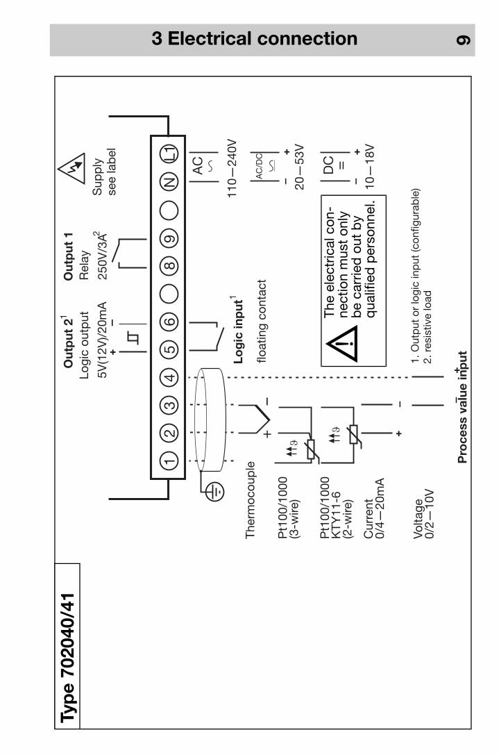
3 Electrical connection 9
20—
53V
10—
18V
AC
/DC
DC
AC
110—
240V
5V(1
2V)/
20m
A
1. O
utp
ut o
r lo
gic
inp
ut (c
onfig
urab
le)
2. r
esis
tive
load
Out
put
1
250V
/3A
Log
ic in
put
Pro
cess
val
ue in
put
+
+ +
– –
+
–+
–
–
NL1
98
65
43
21
Cur
rent
0/4—
20m
A
Pt1
00/1
000
KTY
11-6
(2-w
ire)
Pt1
00/1
000
(3-w
ire)
Ther
moc
oup
le
Volta
ge0/
2—10
V
Out
put
21
2
Logi
c ou
tput
Rel
ay
+–
=
float
ing
cont
act
Sup
ply
see
lab
el
1
VTh
e el
ectr
ical
con
-ne
ctio
n m
ust
only
b
e ca
rrie
d o
ut b
y q
ualif
ied
per
sonn
el.
Typ
e 70
2040
/41

3 Electrical connection 10
20—
53V
AC
/DC
AC
110—
240V
12
Log
ic in
put
Pro
cess
val
ue in
put
+–
-
+
+–
NL1
98
54
32
1
Cur
rent
0/4—
20 m
A
Pt1
00/1
000
KTY
11-6
(2-w
ire)
Pt1
00/1
000
(3-w
ire)
Ther
moc
oup
le
Volta
ge0/
0.2—
1 V
Out
put
s
Rel
ay 2
50 V
/3 A
+–
7
Sup
ply
see
lab
el
10—
18V
DC
+–
=V
The
elec
tric
al c
onne
ctio
n m
ust
only
be
carr
ied
out
b
y q
ualif
ied
per
sonn
el.
Typ
e 70
2040
/41
wit
h2
rela
y o
utp
uts
(op
tio
n)

3 Electrical connection 11
20—
53V
AC
110—
240V
Out
put
2
5V(1
2V)/
20m
A
Cur
rent
0/4—
20m
A
Pt1
00/1
000
KTY
11-6
(2-w
ire)
Pt1
00/1
000
(3-w
ire)
Ther
moc
oup
le
Volta
ge0/
2—10
V
Out
put
3O
utp
ut 1
250V
/3A
250V
/3A
Log
ic in
put
Pro
cess
val
ue in
put+
+–
+
–
+–
–
13N
L112
109
76
54
32
1
float
ing
cont
act
22
Logi
c ou
tput
Rel
ayR
elay
2. r
esis
tive
load
+–
AC
/DC
10—
18V
DC
+–
=
Sup
ply
see
lab
el
Typ
e 70
2042
/43/
44
VTh
e el
ectr
ical
con
nect
ion
mus
t on
ly b
e ca
rrie
d o
ut b
y q
ualif
ied
p
erso
nnel
.
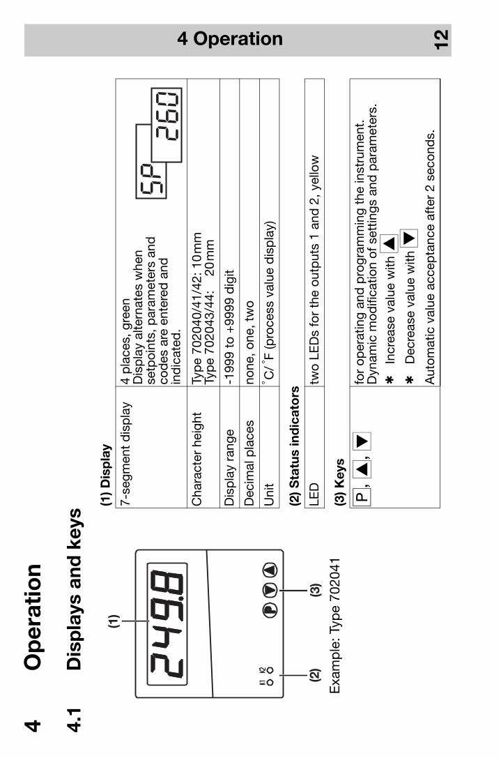
4 Operation 12
4 O
per
atio
n
4.1
Dis
pla
ys a
nd k
eys
(1) D
isp
lay
7-se
gmen
t d
isp
lay
4 p
lace
s, g
reen
Dis
pla
y al
tern
ates
whe
nse
tpoi
nts,
par
amet
ers
and
co
des
are
ent
ered
and
ind
icat
ed.
Cha
ract
er h
eigh
tTy
pe
7020
40/4
1/42
: 10
mm
Typ
e 70
2043
/44:
20
mm
Dis
pla
y ra
nge
-199
9 to
+99
99 d
igit
Dec
imal
pla
ces
none
, one
, tw
o
Uni
t° C
/ °F
(pro
cess
val
ue d
isp
lay)
(2) S
tatu
s in
dic
ato
rs
LED
two
LED
s fo
r th
e ou
tput
s 1
and
2, y
ello
w
(3) K
eys
q, i
, dfo
r op
erat
ing
and
pro
gram
min
g th
e in
stru
men
t.D
ynam
ic m
odifi
catio
n of
set
tings
and
par
amet
ers.
hIn
crea
se v
alue
with
ih
Dec
reas
e va
lue
with
dA
utom
atic
val
ue a
ccep
tanc
e af
ter
2 se
cond
s.
Exa
mp
le: T
ype
7020
41

4 Operation 13
4.2
Pri
ncip
le o
f o
per
atio
nN
orm
al d
isp
lay
The
dis
pla
y sh
ows
the
pro
cess
val
ue.
Op
erat
ing
leve
lTh
e se
tpoi
nt SP is
inp
ut h
ere.
On
activ
e se
tpoi
nt s
witc
hing
via
the
logi
c in
put
, SP1 o
r SP2 a
p-
pea
rs in
the
dis
pla
y. W
hen
the
ram
p fu
nctio
n is
act
ive,
the
ram
p s
etp
oint
SPr
is d
isp
laye
d. W
ithac
tivat
ed t
imer
func
tion,
the
tim
er v
alue
ti
or t
he t
imer
sta
rt v
alue
ti0
is s
how
n.Th
e se
tpoi
nt is
alte
red
dyn
amic
ally
usi
ng t
he i
and
d k
eys.
The
set
ting
will
be
acce
pte
d a
uto-
mat
ical
ly a
fter
ap
pro
x. 2
sec
.
Par
amet
er le
vel
The
setp
oint
s, th
e lim
it va
lue
of th
e lim
it co
mp
arat
or, t
he c
ontr
olle
r p
aram
eter
s an
d th
e ra
mp
slo
-p
e ar
e p
rogr
amm
ed h
ere.
Co
nfig
urat
ion
leve
lTh
e b
asic
func
tions
of t
he c
ontr
olle
r ar
e se
t he
re.
In o
rder
to
mak
e th
e se
ttin
gs,
it is
nec
essa
ry t
o c
hang
e to
the
co
nfig
urat
ion
leve
l A
via
the
par
amet
er y:0 (p
aram
eter
leve
l).T
imer
leve
lTh
e cu
rren
t tim
er v
alue
(on
ly w
hen
the
timer
has
bee
n st
arte
d)
and
the
tim
er s
tart
val
ue a
re a
l-te
red
her
e. T
he p
aram
eter
s at
thi
s le
vel a
re m
arke
d w
ith a
n un
der
scor
e in
the
dis
pla
y.
Tim
e-o
utIf
no o
per
atio
n oc
curs
, the
con
trol
ler
retu
rns
auto
mat
ical
ly to
nor
mal
dis
pla
y af
ter
app
rox.
30
sec
(exc
eptio
n: w
ith t
imer
fun
ctio
ns s
tart
ing
via
pow
er O
N,
the
timer
val
ue is
dis
pla
yed
). If
the
timer
valu
e is
dis
pla
yed
at
the
oper
atin
g le
vel,
time-
out
is n
ot a
ctiv
e.
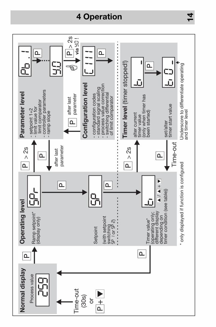
4 Operation 14
Pro
cess
val
ue
Par
amet
er le
vel
Co
nfig
urat
ion
leve
l
Tim
er le
vel(
timer
sto
pp
ed!)
C111
Pb:1
259
- se
tpoi
nt 1
+2
- lim
it va
lue
for
limit
com
par
ator
- co
ntro
ller
par
amet
ers
- ra
mp
slo
pe
Set
poi
nt
(with
set
poi
ntsw
itchi
ngor
)SP1SP2
alte
r cu
rren
ttim
er v
alue
(onl
y w
hen
timer
has
bee
n st
arte
d)
set/
alte
rtim
er s
tart
val
ue
* on
ly d
isp
laye
d if
func
tion
is c
onfig
ured
Ram
p s
etp
oint
*(d
isp
lay
only
)
Tim
er v
alue
*(o
per
atin
g on
ly;
diff
eren
t d
isp
lay
dep
end
ing
ontim
er c
ond
ition
(see
tab
le))
SP
SPr
ti
ti
ti0
- co
nfig
urat
ion
cod
es-
stan
dar
d s
igna
l sca
ling
- p
roce
ss v
alue
cor
rect
ion
- sw
itchi
ng d
iffer
entia
lof
lim
it co
mp
arat
or
Q
> 2
s
qd
+
No
rmal
dis
pla
yO
per
atin
g le
vel
> 2
s
> 2
s
afte
r la
stp
aram
eter
viay.0
!Ti
me-
out
(30s
)
Tim
e-ou
t
or
afte
r la
stp
aram
eter
ii
d/
+
Y.0 A
Und
ersc
ore
to d
iffer
entia
te o
per
atin
gan
d t
imer
leve
l

4 Operation 15
4.3
Op
erat
ion
of
the
tim
er f
unct
ion
The
timer
can
be
oper
ated
with
the
key
s (s
tart
, sto
p, c
ance
l, ac
know
led
ge) i
f the
tim
er a
t op
era-
ting
leve
l is
ind
icat
ed.
Tim
e-ou
t is
not
act
ive
here
. If
the
logi
c in
put
is
conf
igur
ed a
ccor
din
gly,
then
a k
ey, s
uch
as t
he i
key
, can
be
used
. In
this
cas
e, t
he t
imer
can
als
o b
e op
erat
ed e
ven
ifth
e tim
er v
alue
doe
s no
t ap
pea
r in
the
dis
pla
y.
Po
ssib
le d
isp
laye
d p
aram
eter
s fo
r ti
mer
fun
ctio
n at
op
erat
ing
leve
l
Dis
pla
yS
tate
/Act
ion
Dis
pla
yS
tate
/Act
ion
Tim
er n
ot r
unni
ngh
Sta
rt w
ith i
Tim
er h
as s
top
ped
hC
ontin
ue w
ith i
hC
ance
l with
i +
d
Tim
er h
as b
een
star
ted
but
th
e to
lera
nce
limit
has
not
yet
bee
n re
ache
dh
Can
cel w
ith i
+ d
Tim
er h
as r
un d
own
hA
ckno
wle
dge
with
any
key
(tim
er s
tart
val
ue ti0
is
ind
icat
ed)
With
tim
e-d
elay
ed c
ontr
ol
(C12
0=3)
, ack
now
led
ge
with
i +
d
Tim
er r
unni
ng;
ti
is d
isp
laye
dh
Sto
p w
ith i
hC
ance
l with
i +
dW
hen
the
tim
er h
as b
een
star
ted
, the
dec
imal
po
int
in t
he d
isp
lay
for
the
tim
er v
alue
will
blin
k!

5 Functions 16
5 Fu
ncti
ons
We
reco
mm
end
the
follo
win
g p
roce
dur
e:
1.no
t fo
r Ty
pe
7020
40/4
1 w
ith 2
rel
ay o
utp
uts
(op
tion)
hFa
mili
ariz
e yo
urse
lf w
ith t
he c
ontr
olle
r fu
nctio
ns
hE
nter
the
con
figur
atio
n co
des
and
the
par
amet
er v
alue
s in
the
tab
les
pro
vid
ed fo
r th
is p
ur-
pos
e in
Cha
pte
r 6.
Writ
e d
own
the
app
rop
riate
val
ues
(),
or m
ark
sele
ctio
n w
ith a
cro
ss
().
The
par
amet
ers
and
the
con
figur
atio
n co
des
are
list
ed in
the
ord
er o
f the
irap
pea
ranc
e. P
aram
eter
s w
hich
are
not
rel
evan
t ar
e m
aske
d o
ut (s
ee t
able
bel
ow).
hE
nter
the
con
figur
atio
n co
de
and
par
amet
ers
on t
he in
stru
men
t
Co
nfig
urat
ion
Mas
king
out
the
par
amet
ers
for
Par
amet
erS
ingl
e-se
tpoi
nt c
ontr
olle
rD
oub
le-s
etp
oint
con
trol
ler
Pb:2, Cy2, db, HyS.2
Dou
ble
-set
poi
nt c
ontr
olle
rLi
mit
com
p. f
or T
ype
7020
40/4
1Lo
gic
inp
ut fo
r Ty
pe
7020
40/4
11C114, HySt, AL
C117
Lim
it co
mp
arat
or n
o fu
nctio
nLi
mit
com
par
ator
HySt, AL
Lim
it co
mp
arat
or a
ctiv
ated
Logi
c in
put
for
Typ
e70
2040
/411
C117
Res
ista
nce
ther
mom
eter
, the
rmoc
oup
leS
tand
ard
sig
nal s
calin
gSCL, SCH
Ram
p fu
nctio
n of
fR
amp
func
tion
rASd, SPr
Set
poi
nt s
witc
hing
not
act
ivat
edS
etp
oint
s at
the
par
amet
er le
vel
SP1, SP2
Tim
er fu
nctio
n: n
o fu
nctio
nTi
mer
func
tion
ti
, C121, C122, C123
Typ
e 70
2040
/41
Out
put
3C118
X

5 Functions 17
5.1
Pro
cess
val
ue in
put
Sym
bo
lN
ote
s
C111
Tran
sduc
er/p
rob
e (p
roce
ss v
alue
inp
ut)
vp
age
31
C112
Uni
t o
f p
roce
ss v
alue
(°C
/°F)
/dec
imal
pla
ces
of
dis
pla
y v
pag
e31
SCL
Sta
rt/e
nd v
alue
of
valu
e ra
nge
for
stan
dar
d s
igna
ls
vp
age
35E
xam
ple
: 0—
20 m
A→
20—
200
°C: SCL =
20
/ SCH
= 2
00
SCH
OFFS
Pro
cess
val
ue c
orr
ecti
on
v
pag
e35
Usi
ng t
he p
roce
ss v
alue
cor
rect
ion,
a m
easu
red
val
ue c
an b
e co
rrec
ted
by
a p
rogr
amm
able
am
ount
up
war
ds
or d
ownw
ard
s (o
ffset
).Le
ad c
omp
ensa
tion
can
be
imp
lem
ente
d in
sof
twar
e fo
r 2-
wire
circ
uit
thro
ugh
pro
cess
val
ue
corr
ectio
n.
Exa
mp
les:
Mea
sure
d v
alue
O
ffse
t D
isp
laye
d v
alue
29
4.7
+ 0
.3
295.
0 29
5.3
- 0
.3
295.
0
dF
Filt
er t
ime
con
stan
t (d
amp
ing)
to
adap
t th
e d
igita
l inp
ut fi
lter
(0se
c =
filte
r of
f) v
pag
e36
if dF h
igh:
-
high
dam
pin
g of
inte
rfer
ence
sig
nals
- sl
ow r
eact
ion
of t
he p
roce
ss v
alue
dis
pla
y to
cha
nges
in t
he p
roce
ss v
alue
- lo
w c
ut-o
ff fr
eque
ncy
(2nd
ord
er lo
w-p
ass
filte
r)
5 Functions 18
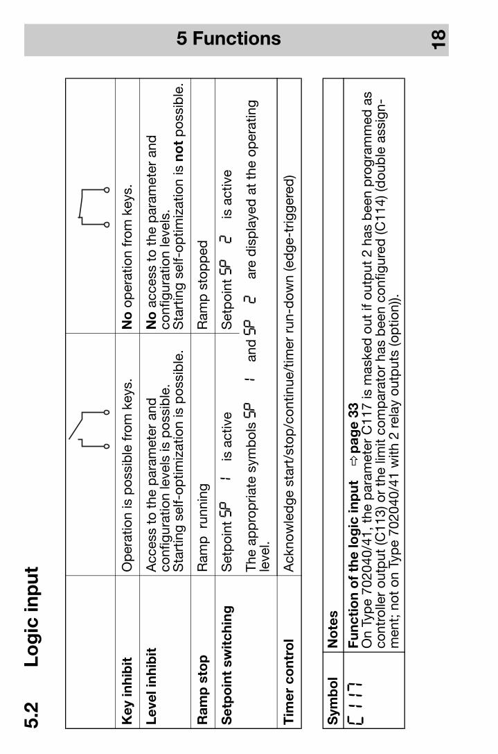
5.2
Log
ic in
put
Key
inhi
bit
O
per
atio
n is
pos
sib
le fr
om k
eys.
N
o o
per
atio
n fr
om k
eys.
Leve
l inh
ibit
Acc
ess
to t
he p
aram
eter
and
conf
igur
atio
n le
vels
is p
ossi
ble
.S
tart
ing
self-
optim
izat
ion
is p
ossi
ble
.
No
acc
ess
to t
he p
aram
eter
and
conf
igur
atio
n le
vels
.S
tart
ing
self-
optim
izat
ion
is n
ot
pos
sib
le.
Ram
p s
top
Ram
p r
unni
ngR
amp
sto
pp
ed
Set
po
int
swit
chin
gS
etp
oint
SP1
is a
ctiv
eS
etp
oint
SP2
is a
ctiv
e
The
app
rop
riate
sym
bol
s SP1
and
SP2
are
dis
pla
yed
at
the
oper
atin
g le
vel.
Tim
er c
ont
rol
Ack
now
led
ge s
tart
/sto
p/c
ontin
ue/t
imer
run
-dow
n (e
dge
-trig
gere
d)
Sym
bo
lN
ote
s
C117
Func
tio
n o
f th
e lo
gic
inp
ut
vp
age
33O
n Ty
pe
7020
40/4
1, t
he p
aram
eter
C11
7 is
mas
ked
out
if o
utp
ut 2
has
bee
n p
rogr
amm
ed a
s co
ntro
ller
outp
ut (C
113)
or
the
limit
com
par
ator
has
bee
n co
nfig
ured
(C11
4) (d
oub
le a
ssig
n-m
ent;
not
on
Typ
e 70
2040
/41
with
2 r
elay
out
put
s (o
ptio
n)).

5 Functions 19
5.3
Co
ntro
ller
Co
ntro
ller
stru
ctur
eTh
e co
ntro
ller
stru
ctur
e is
def
ined
via
the
par
amet
ers Pb, dt a
nd rt.
Exa
mp
le: S
ettin
g fo
r P
I con
trol
ler →
Pb.1
=12
0, dt=
0se
c, rt=
350
sec
Sym
bo
lN
ote
s
C113
Co
ntro
ller
typ
e an
d a
ssig
nmen
t o
f th
e co
ntro
ller
out
put
s to
the
phy
sica
lo
utp
uts
1+2
v
pag
e32
C116
Out
put
s in
fau
lt c
ond
itio
n v
pag
e33
The
switc
hing
sta
tes
of t
he o
utp
uts
are
def
ined
her
e in
the
eve
nt o
f ove
r/un
der
rang
e, p
rob
e b
reak
/sho
rt c
ircui
t or
dis
pla
y ov
erflo
w.
vC
hap
ter
7
C118
Ass
ignm
ent
of
the
out
put
s v
pag
e33
Onl
y fo
r Ty
pe
7020
42/4
3/44
; ove
rwrit
es t
he a
ssig
nmen
t of
C113
(con
trol
ler
typ
e as
C113
)
Pb:1
Pro
po
rtio
nal b
and
1 (c
ontr
olle
r ou
tput
1)
vp
age
36P
rop
ort
iona
l ban
d 2
(con
trol
ler
outp
ut 2
)In
fluen
ces
the
P a
ctio
n of
the
con
trol
ler.
If Pb
=0,
the
con
trol
ler
stru
ctur
e is
not
effe
ctiv
e.Pb:2
dt
Der
ivat
ive
tim
e v
pag
e36
Influ
ence
s th
e D
act
ion
of t
he c
ontr
olle
r. If dt=
0, t
he c
ontr
olle
r ha
s no
D a
ctio
n.
rt
Res
et t
ime
v
pag
e36
Influ
ence
s th
e I a
ctio
n of
the
con
trol
ler.
If rt=
0, t
he c
ontr
olle
r ha
s no
I ac
tion.
Cy1
Cyc
le t
ime
1 (c
ontr
olle
r ou
tput
1)
vp
age
36C
ycle
tim
e 2
(con
trol
ler
outp
ut 2
)Th
e cy
cle
time
has
to b
e se
lect
ed s
o th
at t
he e
nerg
y su
pp
ly t
o th
e p
roce
ss is
virt
ually
cont
inuo
us, w
hile
not
sub
ject
ing
the
switc
hing
ele
men
ts t
o ex
cess
ive
wea
r. Cy2
5 Functions 20
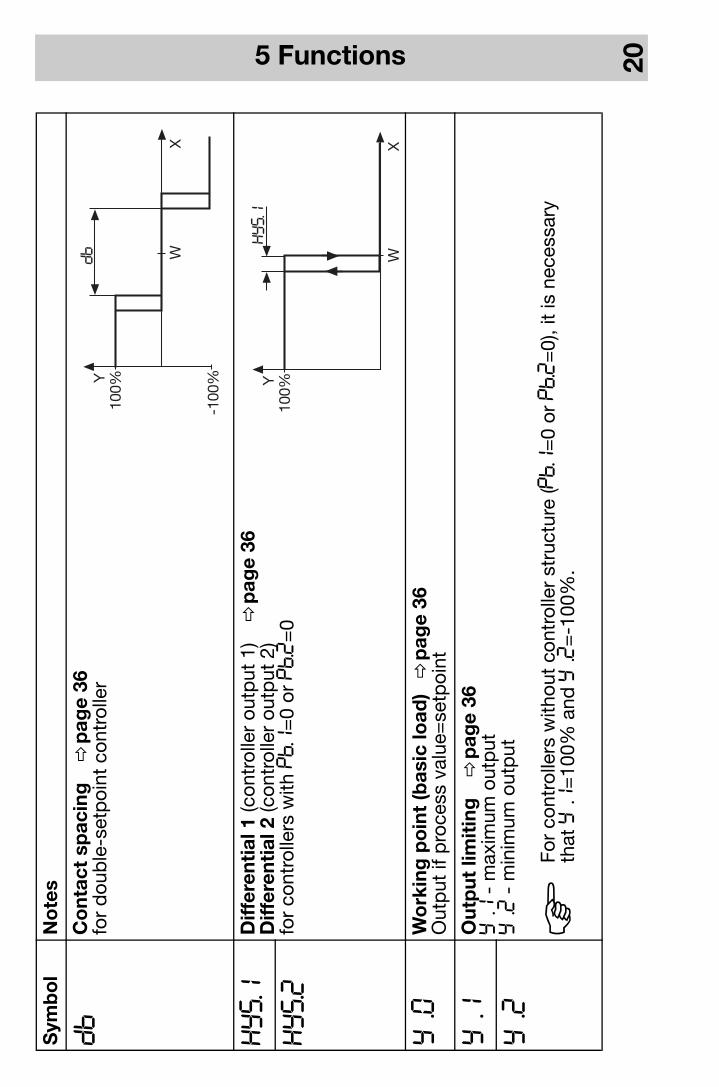
db
Co
ntac
t sp
acin
g
vp
age
36fo
r d
oub
le-s
etp
oint
con
trol
ler
HYS.1
Diff
eren
tial
1 (c
ontr
olle
r ou
tput
1)
vp
age
36D
iffer
enti
al 2
(con
trol
ler
outp
ut 2
)fo
r co
ntro
llers
with
Pb.1
=0
or Pb.2
=0
HYS.2
Y:0
Wo
rkin
g p
oin
t (b
asic
load
) v
pag
e36
Out
put
if p
roce
ss v
alue
=se
tpoi
nt
Y:1
Out
put
lim
itin
g
vp
age
36y:1
- m
axim
um o
utp
uty:2
- m
inim
um o
utp
utY:2
Sym
bo
lN
ote
s
HFo
r co
ntro
llers
with
out
cont
rolle
r st
ruct
ure
(Pb.1
=0
or Pb.2
=0)
, it
is n
eces
sary
that
y:1
=10
0% a
nd y:2
=-1
00%
.
5 Functions 21
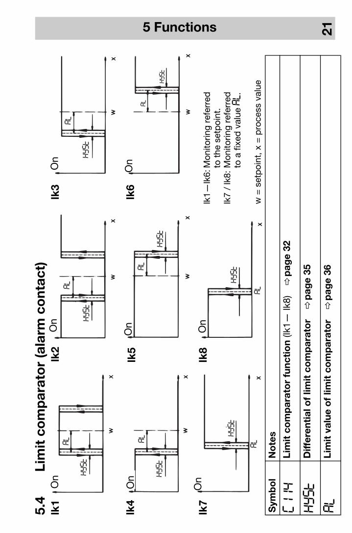
5.4
Lim
it c
om
par
ato
r (a
larm
co
ntac
t)
Sym
bo
lN
ote
s
C114
Lim
it c
om
par
ato
r fu
ncti
on
(lk1—
lk8)
v
pag
e32
Hyst
Diff
eren
tial
of
limit
co
mp
arat
or
v
pag
e35
AL
Lim
it v
alue
of
limit
co
mp
arat
or
v
pag
e36
lk2
lk3
lk4
lk5
lk6
lk7
lk8
lk1
lk1—
lk6:
Mon
itorin
g re
ferr
edto
the
set
poi
nt.
lk7
/ lk
8:M
onito
ring
refe
rred
to a
fixe
d v
alue
AL.
w =
set
poi
nt, x
= p
roce
ss v
alue
On
On
On
On
On
On
On
On
5 Functions 22
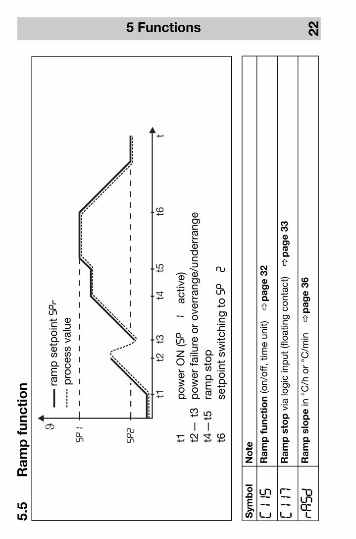
5.5
Ram
p f
unct
ion
Sym
bo
lN
ote
C115
Ram
p f
unct
ion
(on/
off,
time
unit)
v
pag
e32
C117
Ram
p s
top
via
logi
c in
put
(flo
atin
g co
ntac
t) v
pag
e33
rAsd
Ram
p s
lop
e in
°C
/h o
r °C
/min
v
pag
e36
t1
SP1
SP2
t2t3
t4t5
t6t
t1p
ower
ON
(SP1
activ
e)t2
— t
3p
ower
failu
re o
r ov
erra
nge/
und
erra
nge
t4—
t5ra
mp
sto
pt6
setp
oint
sw
itchi
ng t
o SP2
ram
p s
etp
oint
SPr
pro
cess
val
ue
5 Functions 23
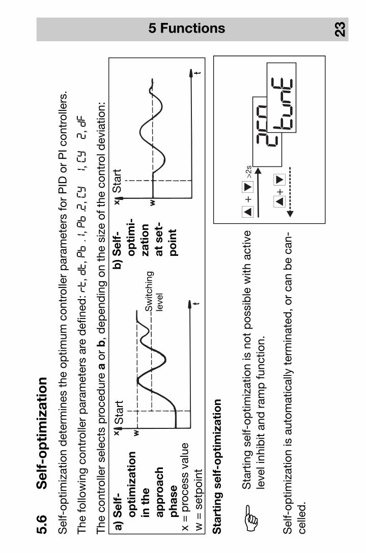
5.6
Sel
f-o
pti
miz
atio
nS
elf-
optim
izat
ion
det
erm
ines
the
op
timum
con
trol
ler
par
amet
ers
for
PID
or
PI c
ontr
olle
rs.
The
follo
win
g co
ntro
ller
par
amet
ers
are
def
ined
: rt, dt, Pb:1, Pb:2, Cy1, Cy2, dF
The
cont
rolle
r se
lect
s p
roce
dur
e a
or b
, dep
end
ing
on t
he s
ize
of t
he c
ontr
ol d
evia
tion:
Sta
rtin
g s
elf-
op
tim
izat
ion
Sel
f-op
timiz
atio
n is
aut
omat
ical
ly t
erm
inat
ed, o
r ca
n b
e ca
n-ce
lled
.
HS
tart
ing
self-
optim
izat
ion
is n
ot p
ossi
ble
with
act
ive
leve
l inh
ibit
and
ram
p fu
nctio
n.
a) S
elf-
op
tim
izat
ion
in t
heap
pro
ach
pha
se
b) S
elf-
op
tim
i-za
tio
nat
set
-p
oin
t
Sta
rtS
tart
x =
pro
cess
val
uew
= s
etp
oint
Sw
itchi
ngle
vel
260tunE
i+d
>2s
i+d
5 Functions 24
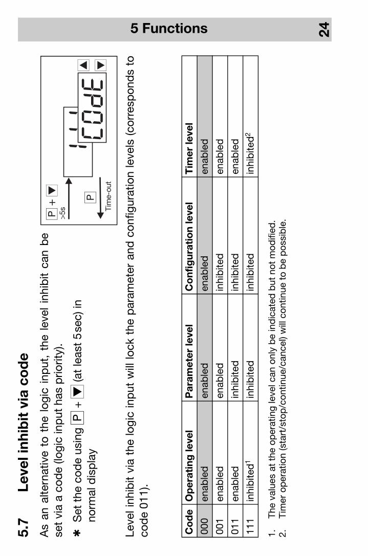
5.7
Leve
l inh
ibit
via
co
de
As
an a
ltern
ativ
e to
the
log
ic i
nput
, th
e le
vel
inhi
bit
can
be
set
via
a co
de
(logi
c in
put
has
prio
rity)
.
hS
et t
he c
ode
usin
g q
+ d
(at
leas
t 5
sec)
inno
rmal
dis
pla
y
Leve
l inh
ibit
via
the
logi
c in
put
will
lock
the
par
amet
er a
nd c
onfig
urat
ion
leve
ls (
corr
esp
ond
s to
cod
e 01
1).
1.
The
valu
es a
t th
e op
erat
ing
leve
l can
onl
y b
e in
dic
ated
but
not
mod
ified
.2.
Tim
er o
per
atio
n (s
tart
/sto
p/c
ontin
ue/c
ance
l) w
ill c
ontin
ue t
o b
e p
ossi
ble
.
Co
de
Op
erat
ing
leve
lP
aram
eter
leve
lC
onf
igur
atio
n le
vel
Tim
er le
vel
000
enab
led
enab
led
enab
led
enab
led
001
enab
led
enab
led
inhi
bite
den
able
d
011
enab
led
inhi
bite
din
hib
ited
enab
led
111
inhi
bite
d1
inhi
bite
din
hib
ited
inhi
bite
d2
5 Functions 25
5.8
Tim
er f
unct
ion
(ext
ra c
od
e)U
sing
the
tim
er f
unct
ion,
the
con
trol
act
ion
can
be
influ
ence
d b
y m
eans
of
the
adju
stab
le t
ime
ti0
. Aft
er t
he t
imer
has
bee
n st
arte
d b
y p
ower
ON
, by
pre
ssin
g th
e ke
y, o
r vi
a th
e lo
gic
inp
ut,
the
timer
sta
rt v
alue
ti0
is c
ount
ed d
own
to 0
, ei
ther
inst
antly
or
afte
r th
e p
roce
ss v
alue
has
gone
ab
ove
or b
elow
a p
rogr
amm
able
tol
eran
ce l
imit.
Whe
n th
e tim
er h
as r
un d
own,
sev
eral
even
ts a
re t
rigge
red
, suc
h as
con
trol
sw
itch-
off
(out
put
0%
) and
set
poi
nt s
witc
hing
. Fur
ther
mo-
re, i
t is
pos
sib
le t
o im
ple
men
t tim
er s
igna
lling
via
an
outp
ut. w
- se
tpoi
ntx
- p
roce
ss v
alue
SP
- p
rogr
amm
ed s
etp
oint
ti0
- tim
er s
tart
val
ue--
---
- tim
er s
igna
lling
(he
re: C
122=
1)i
- in
crem
ent
key
Exa
mp
le:
5 Functions 26
No
tes
on
the
tim
er f
unct
ion
in c
onj
unct
ion
wit
h th
e ra
mp
fun
ctio
n
-G
ener
ally
, the
set
poi
nts
can
also
be
app
roac
hed
usi
ng t
he r
amp
func
tion.
-S
top
pin
g th
e tim
er d
oes
not
influ
ence
the
ram
p fu
nctio
n.
-If
cont
rol i
s ac
tive
afte
r th
e tim
er h
as r
un d
own,
the
cur
rent
set
poi
nt is
ap
pro
ache
d w
ith t
he
ram
p. C
ance
llatio
n of
the
tim
er is
follo
wed
by
a se
tpoi
nt s
tep
with
out
ram
p.
-Fo
r tim
er fu
nctio
ns w
ith a
tol
eran
ce li
mit,
onl
y th
e se
tpoi
nt (=
ram
p e
nd v
alue
) is
mon
itore
d.
No
te o
n se
tpo
int
swit
chin
g v
ia t
he lo
gic
inp
ut
-S
etp
oint
sw
itchi
ng v
ia t
he lo
gic
inp
ut is
gen
eral
ly p
ossi
ble
. An
exce
ptio
n he
re is
the
tim
er
func
tion
“Tim
e-d
epen
den
t set
poi
nt s
witc
hing
”. In
this
cas
e, c
onfig
ured
set
poi
nt s
witc
hing
via
th
e lo
gic
inp
ut w
ill n
ot b
e ac
tive.
No
te o
n th
e d
isp
lay
stat
us in
the
eve
nt o
f a
po
wer
fai
lure
-Th
e st
ate
of t
he d
isp
lay
bef
ore
the
pow
er fa
ilure
will
be
rest
ored
, exc
ept
for
even
ts t
hat
are
rela
ted
to
the
timer
(sta
rt, c
ance
l, co
ntin
ue, s
top
). Th
en t
he t
imer
val
ue w
ill b
e sh
own
in t
he
dis
pla
y.
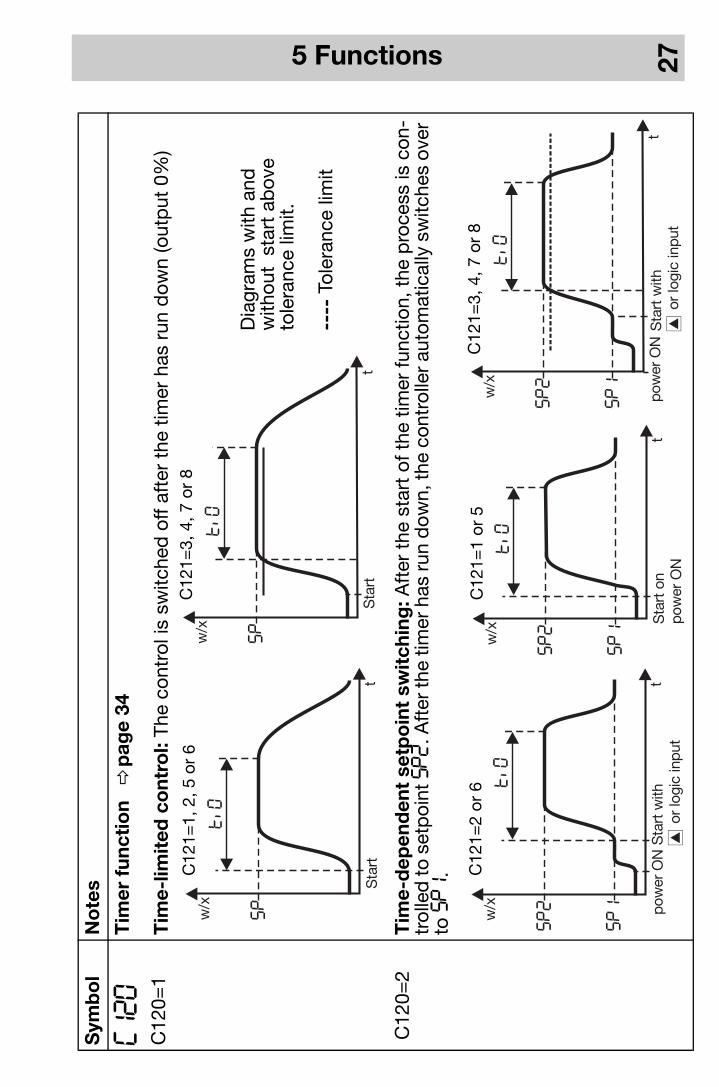
5 Functions 27
Sym
bo
lN
ote
s
C120
C12
0=1
Tim
er f
unct
ion
v
pag
e34
Tim
e-lim
ited
co
ntro
l: Th
e co
ntro
l is
switc
hed
off
afte
r th
e tim
er h
as r
un d
own
(out
put
0%)
C12
0=2
Tim
e-d
epen
den
t se
tpo
int
swit
chin
g: A
fter
the
sta
rt o
f the
tim
er fu
nctio
n, t
he p
roce
ss is
con
-tr
olle
d to
set
poi
nt SP2
. Aft
er th
e tim
er h
as ru
n d
own,
the
cont
rolle
r aut
omat
ical
ly s
witc
hes
over
to
SP1
.
C12
1=3,
4, 7
or
8C
121=
1, 2
, 5 o
r 6
Dia
gram
s w
ith a
ndw
ithou
t s
tart
ab
ove
tole
ranc
e lim
it.
----
Tol
eran
ce li
mit
C12
1=2
or 6
C12
1=1
or 5
C12
1=3,
4, 7
or
8

5 Functions 28
C120
C12
0=3
Tim
e-d
elay
ed c
ont
rol:
The
cont
rol a
ctio
n st
arts
aft
er t
he t
imer
has
run
dow
n.
C12
0=4
Tim
er: A
fter
the
sta
rt o
f the
tim
er fu
nctio
n, ti0
is c
ount
ed d
own
to 0
. The
con
trol
act
ion
is
ind
epen
den
t of
the
tim
er. H
ere,
too
, the
tim
er r
un-d
own
can
be
sign
alle
d v
ia a
n ou
tput
.
Sym
bo
lN
ote
s
HA
fter
the
tim
er h
as r
un d
own
(End
), th
ei
+ d
key
s ar
e us
ed fo
r ac
know
led
ge-
men
t.S
et ti0
> 0
s
C12
1=1,
2, 5
or
6
C12
1=1,
2, 5
or
6
C12
2=1
Tim
er s
igna
lling
C12
2=3
5 Functions 29
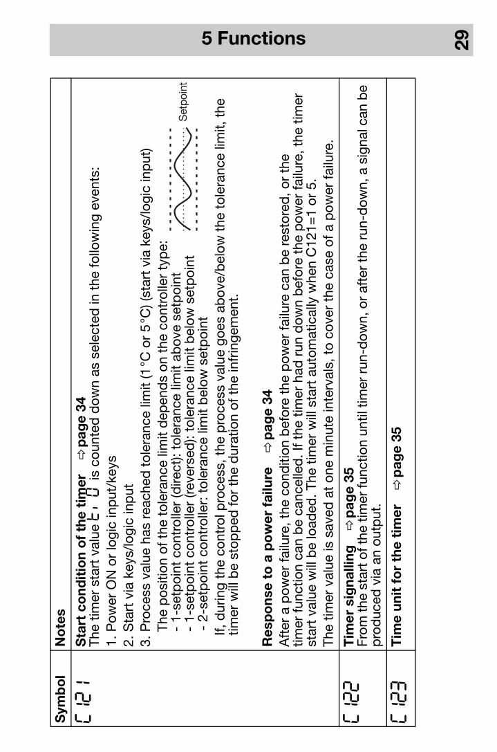
C121
Sta
rt c
ond
itio
n o
f th
e ti
mer
v
pag
e34
The
timer
sta
rt v
alue
ti0
is c
ount
ed d
own
as s
elec
ted
in t
he fo
llow
ing
even
ts:
1. P
ower
ON
or
logi
c in
put
/key
s2.
Sta
rt v
ia k
eys/
logi
c in
put
3. P
roce
ss v
alue
has
rea
ched
tol
eran
ce li
mit
(1°C
or
5°C
) (st
art
via
keys
/logi
c in
put
)
The
pos
ition
of t
he t
oler
ance
lim
it d
epen
ds
on t
he c
ontr
olle
r ty
pe:
-
1-s
etp
oint
con
trol
ler
(dire
ct):
tole
ranc
e lim
it ab
ove
setp
oint
-
1-s
etp
oint
con
trol
ler
(reve
rsed
): to
lera
nce
limit
bel
ow s
etp
oint
-
2-s
etp
oint
con
trol
ler:
tol
eran
ce li
mit
bel
ow s
etp
oint
If,
dur
ing
the
cont
rol p
roce
ss, t
he p
roce
ss v
alue
goe
s ab
ove/
bel
ow t
he t
oler
ance
lim
it, t
he
timer
will
be
stop
ped
for
the
dur
atio
n of
the
infr
inge
men
t.
Res
po
nse
to a
po
wer
fai
lure
v
pag
e34
Aft
er a
pow
er fa
ilure
, the
con
diti
on b
efor
e th
e p
ower
failu
re c
an b
e re
stor
ed, o
r th
etim
er fu
nctio
n ca
n b
e ca
ncel
led
. If t
he t
imer
had
run
dow
n b
efor
e th
e p
ower
failu
re, t
he t
imer
st
art
valu
e w
ill b
e lo
aded
. The
tim
er w
ill s
tart
aut
omat
ical
ly w
hen
C12
1=1
or 5
.Th
e tim
er v
alue
is s
aved
at
one
min
ute
inte
rval
s, t
o co
ver
the
case
of a
pow
er fa
ilure
.
C122
Tim
er s
igna
lling
v
pag
e35
From
the
star
t of t
he ti
mer
func
tion
until
tim
er r
un-d
own,
or
afte
r th
e ru
n-d
own,
a s
igna
l can
be
pro
duc
ed v
ia a
n ou
tput
.
C123
Tim
e un
it f
or
the
tim
er
vp
age
35
Sym
bo
lN
ote
s

5 Functions 30
Pro
gra
mm
ing
exa
mp
le
Aft
er t
he s
tart
via
the
logi
c in
put
or
from
the
key
s, t
he p
roce
ss h
as t
o b
e co
ntro
lled
for
30
min
-ut
es t
o a
setp
oint
of 8
0°C
. The
con
trol
act
ion
is t
o b
e ca
ncel
led
in t
he e
vent
of a
pow
er fa
ilure
.
Con
figur
atio
n:
-C
111
— C
116:
Con
trol
ler
pro
gram
min
g
-C
117=
5: L
ogic
inp
ut =
tim
er c
ontr
ol
-C
120=
1: T
imer
func
tion
= t
ime-
limite
d c
ontr
ol
-C
121=
6: S
tart
con
diti
on fo
r tim
er =
via
logi
c in
put
/key
s -
canc
ella
tion
on p
ower
failu
re
-C
122=
0: T
imer
sig
nalli
ng =
no
func
tion
-C
123=
1: T
ime
unit
(tim
er) =
mm
.ss
Op
erat
ion:
hE
nter
the
set
poi
nt SP (8
0°C
)
hP
ress
the
q k
ey u
ntil
ti0
is in
dic
ated
hC
hang
e ov
er to
the
timer
leve
l usi
ng q
(at l
east
2se
c)
hE
nter
the
tim
er s
tart
val
ue ti0
_ (3
0.00
)
hR
etur
n to
the
op
erat
ing
leve
l (tim
er v
alue
) with
q
hS
tart
the
con
trol
act
ion
via
the
logi
c in
put
or
with
i
6 Configuration and parameter tables 31
6 C
onf
igur
atio
n an
d p
aram
eter
tab
les
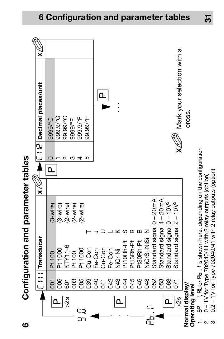
C111
Tran
sdu
cer
X
001
Pt
100
(3-w
ire)
006
Pt
1000
(3-w
ire)
601
KTY
11-6
(2-w
ire)
003
Pt
100
(2-w
ire)
005
Pt
1000
(2-w
ire)
039
Cu-
Con
T
040
Fe-C
on
J04
1C
u-C
on
U04
2Fe
-Con
L
043
NiC
r-N
i K
044
Pt1
0Rh-
Pt
S04
5P
t13R
h-P
t R
046
Pt3
0Rh-
Pt
B04
8N
iCrS
i-N
iSi
N05
2S
tand
ard
sig
nal 0
–20
mA
053
Sta
ndar
d s
igna
l 4–
20m
A06
3S
tand
ard
sig
nal 0
–10
V2
071
Sta
ndar
d s
igna
l 2–
10V
3
C112
Dec
imal
pla
ces/
unit
X
099
99/°
C1
999.
9/°C
299
.99/
°C3
9999
/°F
499
9.9/
°F5
99.9
9/°F
q
q
q
Pb:1
1 >2
s
q. . .
y:0
q >2
s
X
Mar
k yo
ur s
elec
tion
with
a
c
ross
.
1. SP1
, AL o
r Pb:1
is s
how
n he
re, d
epen
din
g on
the
con
figur
atio
n2.
0–
1V
for
Typ
e 70
2040
/41
with
2 r
elay
out
put
s (o
ptio
n)3.
0.2
–1
V fo
r Ty
pe
7020
40/4
1 w
ith 2
rel
ay o
utp
uts
(op
tion)
No
rmal
dis
pla
y/O
per
atin
g le
vel
. . .
6 Configuration and parameter tables 32
1. A
pro
gram
med
lim
it co
mp
arat
or (L
K) h
as p
riorit
yov
er t
he t
imer
sig
nalli
ng.
Furt
her
sett
ings
for
the
outp
uts
with
Typ
e 70
2042
/43/
44, s
ee C
118.
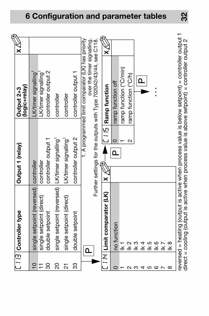
C113
Co
ntro
ller
typ
eO
utp
ut 1
(rel
ay)
Out
put
2+
3 (lo
gic
+re
lay)
X
10si
ngle
set
poi
nt (r
ever
sed
)co
ntro
ller
LK/t
imer
sig
nalli
ng1
11si
ngle
set
poi
nt (d
irect
)co
ntro
ller
LK/t
imer
sig
nalli
ng1
30d
oub
le s
etp
oint
cont
rolle
r ou
tput
1co
ntro
ller
outp
ut 2
20si
ngle
set
poi
nt (r
ever
sed
)LK
/tim
er s
igna
lling
1co
ntro
ller
21si
ngle
set
poi
nt (d
irect
)LK
/tim
er s
igna
lling
1co
ntro
ller
33d
oub
le s
etp
oint
cont
rolle
r ou
tput
2co
ntro
ller
outp
ut 1
q
C114
Lim
it c
om
par
ato
r (L
K)
X
0no
func
tion
1lk
12
lk 2
3lk
34
lk 4
5lk
56
lk 6
7lk
78
lk 8
C115
Ram
p f
unc
tio
nX
0ra
mp
func
tion
off
1ra
mp
func
tion
(°C
/min
)2
ram
p fu
nctio
n (°
C/h
)
q
q
reve
rsed
= h
eatin
g (o
utp
ut is
act
ive
whe
n p
roce
ss v
alue
is b
elow
set
poi
nt) =
con
trol
ler
outp
ut 1
dire
ct =
coo
ling
(out
put
is a
ctiv
e w
hen
pro
cess
val
ue is
ab
ove
setp
oint
) = c
ontr
olle
r ou
tput
2
. . .
6 Configuration and parameter tables 33
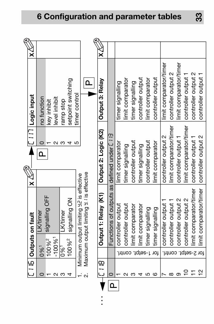
C116
Out
put
s o
n f
ault
X
00
%1
LK/t
imer
si
gnal
ling
OFF
110
0%
2
2-1
00%
1 3
0%
1 LK
/tim
ersi
gnal
ling
ON
410
0%
2
C117
Log
ic in
put
X
0no
func
tion
1ke
y in
hib
it2
leve
l inh
ibit
3ra
mp
sto
p4
setp
oint
sw
itchi
ng5
timer
con
trol
qC118
Out
put
1: R
elay
(K1)
Out
put
2: L
og
ic (K
2)O
utp
ut 3
: Rel
ayX
0Fu
nctio
ns o
f out
put
s as
def
ined
und
er C113
1
for 1-setpt. contrl.
cont
rolle
r ou
tput
limit
com
par
ator
timer
sig
nalli
ng2
cont
rolle
r ou
tput
timer
sig
nalli
nglim
it co
mp
arat
or3
limit
com
par
ator
cont
rolle
r ou
tput
timer
sig
nalli
ng4
limit
com
par
ator
timer
sig
nalli
ngco
ntro
ller
outp
ut5
timer
sig
nalli
ngco
ntro
ller
outp
utlim
it co
mp
arat
or6
timer
sig
nalli
nglim
it co
mp
arat
orco
ntro
ller
outp
ut
7
for 2-setpt. contrl.
cont
rolle
r ou
tput
1co
ntro
ller
outp
ut 2
limit
com
par
ator
/tim
er8
cont
rolle
r ou
tput
1lim
it co
mp
arat
or/t
imer
cont
rolle
r ou
tput
29
cont
rolle
r ou
tput
2co
ntro
ller
outp
ut 1
limit
com
par
ator
/tim
er10
cont
rolle
r ou
tput
2lim
it co
mp
arat
or/t
imer
cont
rolle
r ou
tput
111
limit
com
par
ator
/tim
erco
ntro
ller
outp
ut 1
cont
rolle
r ou
tput
212
limit
com
par
ator
/tim
erco
ntro
ller
outp
ut 2
cont
rolle
r ou
tput
1
q
q
1.M
inim
um o
utp
ut li
miti
ng y.2
is e
ffec
tive
2.
Max
imum
out
put
lim
iting
y.1
is e
ffec
tive
. . .
6 Configuration and parameter tables 34
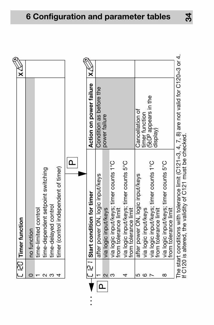
C120
Tim
er f
unc
tio
nX
0no
func
tion
1tim
e-lim
ited
con
trol
2tim
e-d
epen
den
t se
tpoi
nt s
witc
hing
3tim
e-d
elay
ed c
ontr
ol4
timer
(con
trol
ind
epen
den
t of
tim
er)
C121
Sta
rt c
ond
itio
n fo
r ti
mer
Act
ion
on
po
wer
fai
lure
X1
afte
r p
ower
ON
, log
ic in
put
/key
sC
ond
ition
as
bef
ore
the
pow
er fa
ilure
2vi
a lo
gic
inp
ut/k
eys
3vi
a lo
gic
inp
ut/k
eys;
tim
er c
ount
s 1°
C
from
tol
eran
ce li
mit
4vi
a lo
gic
inp
ut/k
eys;
tim
er c
ount
s 5°
C
from
tol
eran
ce li
mit
5af
ter
pow
er O
N, l
ogic
inp
ut/k
eys
Can
cella
tion
oftim
er fu
nctio
n ( StOP a
pp
ears
in t
hed
isp
lay)
6vi
a lo
gic
inp
ut/k
eys
7vi
a lo
gic
inp
ut/k
eys;
tim
er c
ount
s 1°
Cfr
om t
oler
ance
lim
it8
via
logi
c in
put
/key
s; t
imer
cou
nts
5°C
from
tol
eran
ce li
mit
q
q
The
star
t co
nditi
ons
with
tol
eran
ce li
mit
(C12
1=3,
4, 7
, 8) a
re n
ot v
alid
for
C12
0=3
or 4
.If
C12
0 is
alte
red
, the
val
idity
of C
121
mus
t b
e ch
ecke
d.
. . .
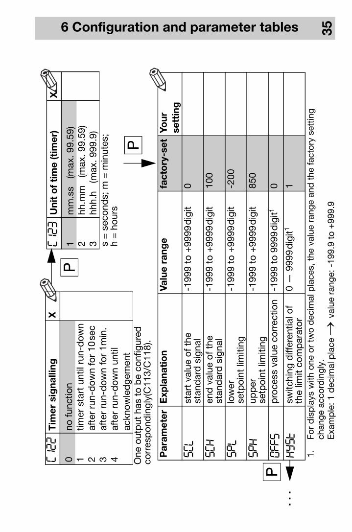
6 Configuration and parameter tables 35
Par
amet
erE
xpla
nati
on
Valu
e ra
nge
fact
ory
-set
Your
sett
ing
SCL
star
t va
lue
of t
hest
and
ard
sig
nal
-199
9to
+99
99d
igit
0
sCH
end
val
ue o
f the
stan
dar
d s
igna
l-1
999
to+
9999
dig
it10
0
SPL
low
erse
tpoi
nt li
miti
ng-1
999
to+
9999
dig
it-2
00
SPH
upp
erse
tpoi
nt li
miti
ng-1
999
to+
9999
dig
it85
0
OFFS
pro
cess
val
ue c
orre
ctio
n-1
999
to99
99d
igit1
0
HySt
switc
hing
diff
eren
tial o
f th
e lim
it co
mp
arat
or0
—99
99d
igit1
1
1.Fo
r d
isp
lays
with
one
or
two
dec
imal
pla
ces,
the
val
ue r
ange
and
the
fact
ory
sett
ing
chan
ge a
ccor
din
gly.
Exa
mp
le: 1
dec
imal
pla
ce →
valu
e ra
nge:
-19
9.9
to +
999.
9
q
C122
Tim
er s
igna
lling
X
0no
func
tion
1tim
er s
tart
unt
il ru
n-d
own
2af
ter r
un-d
own
for 1
0se
c 3
afte
r ru
n-d
own
for
1min
.4
afte
r ru
n-d
own
until
ackn
owle
dge
men
t
qC123
Uni
t o
f ti
me
(tim
er)
X
1m
m.s
s (
max
. 99.
59)
2hh
.mm
(m
ax. 9
9.59
)3
hhh.
h (
max
. 999
.9)
s =
sec
ond
s; m
= m
inut
es;
h =
hou
rs
q
. . .
One
out
put
has
to
be
conf
igur
edco
rres
pon
din
gly(
C11
3/C
118)
.

6 Configuration and parameter tables 36
1.For
dis
pla
ys w
ith o
ne o
r tw
o d
ecim
al p
lace
s, t
he v
alue
ran
ge a
nd t
he fa
ctor
y se
ttin
gch
ange
acc
ord
ingl
y.
Par
amet
erE
xpla
nati
on
Valu
e ra
nge
fact
ory
-se
tYo
ur
sett
ing
sP 1
setp
oint
1S
PL
—S
PH
0
sP 2
setp
oint
2S
PL
—S
PH
0
AL
limit
valu
e of
limit
com
par
ator
-199
9to
+99
99d
igit
0
Pb:1
pro
por
tiona
l ban
d 1
0—
9999
dig
it1 0
Pb:2
pro
por
tiona
l ban
d 2
0—
9999
dig
it10
dt
der
ivat
ive
time
0—
9999
sec
80se
c
rt
rese
t tim
e0
—99
99se
c35
0se
c
Cy 1
cycl
e tim
e 1
1.0
—99
9.9
sec
20.0
sec
Cy 2
cycl
e tim
e 2
1.0
—99
9.9
sec
20.0
sec
db
cont
act
spac
ing
0—
1000
dig
it1 0
HYS.1
diff
eren
tial 1
0—
9999
dig
it1 1
HYS.2
diff
eren
tial 2
0—
9999
dig
it1
1
Y:0
wor
king
poi
nt-1
00to
100
%
0%
Y:1
max
imum
out
put
0—
100
%10
0%
Y:2
min
imum
out
put
-100
to+
100
%-1
00%
dF
filte
r tim
e co
nsta
nt0.
0—
100.
0se
c0.
6se
c
rAsd
ram
p s
lop
e0
—99
9 °C
/h (°
C/m
in)1
0
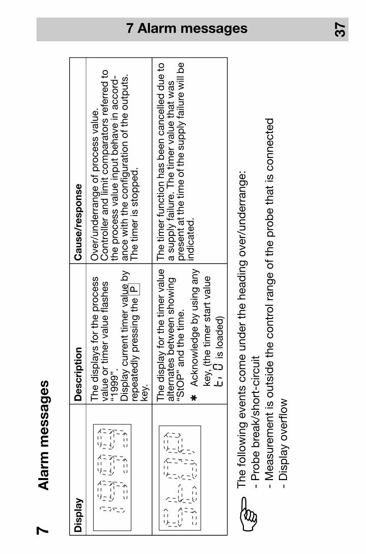
7 Alarm messages 37
7 A
larm
mes
sag
es
Dis
pla
yD
escr
ipti
on
Cau
se/r
esp
ons
e
The
dis
pla
ys fo
r th
e p
roce
ss
valu
e or
tim
er v
alue
flas
hes
“199
9”.
Dis
pla
y cu
rren
t tim
er v
alue
by
rep
eate
dly
pre
ssin
g th
e q
ke
y.
Ove
r/un
der
rang
e of
pro
cess
val
ue.
Con
trol
ler
and
lim
it co
mp
arat
ors
refe
rred
to
the
pro
cess
val
ue in
put
beh
ave
in a
ccor
d-
ance
with
the
con
figur
atio
n of
the
out
put
s.Th
e tim
er is
sto
pp
ed.
The
dis
pla
y fo
r th
e tim
er v
alue
al
tern
ates
bet
wee
n sh
owin
g “S
tOP
” an
d t
he t
ime.
hA
ckno
wle
dge
by
usin
g an
y ke
y, (t
he t
imer
sta
rt v
alue
ti0
is lo
aded
)
The
timer
func
tion
has
bee
n ca
ncel
led
due
to
a su
pp
ly fa
ilure
. The
tim
er v
alue
tha
t w
asp
rese
nt a
t the
tim
e of
the
sup
ply
failu
re w
ill b
e in
dic
ated
.
HTh
e fo
llow
ing
even
ts c
ome
und
er t
he h
ead
ing
over
/und
erra
nge:
- P
rob
e b
reak
/sho
rt-c
ircui
t-
Mea
sure
men
t is
out
sid
e th
e co
ntro
l ran
ge o
f the
pro
be
that
is c
onne
cted
- D
isp
lay
over
flow
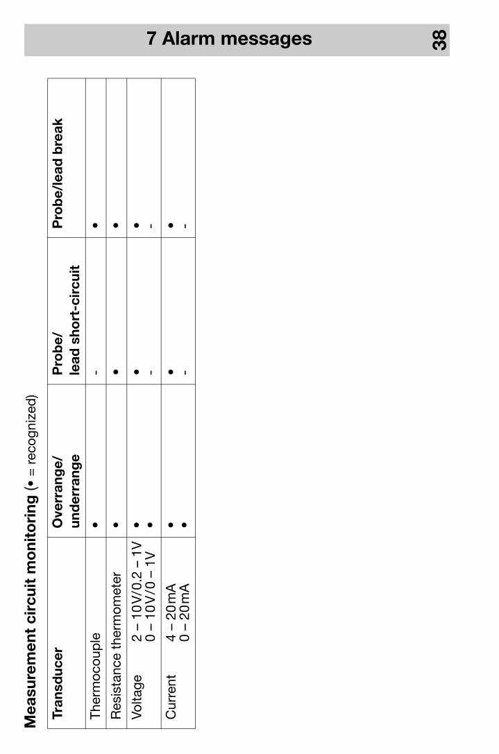
7 Alarm messages 38
Mea
sure
men
t ci
rcui
t m
oni
tori
ng (•
= r
ecog
nize
d)
Tran
sduc
erO
verr
ang
e/un
der
rang
eP
rob
e/le
ad s
hort
-cir
cuit
Pro
be/
lead
bre
ak
Ther
moc
oup
le•
-•
Res
ista
nce
ther
mom
eter
••
•
Volta
ge
2 –
10V
/0.2
– 1
V0
– 10
V/0
– 1
V• •
• -• -
Cur
rent
4 –
20m
A0
– 20
mA
• •• -
• -

8 Technical data 39
8 Te
chni
cal d
ata
Inp
ut f
or
ther
mo
coup
le
1. A
ccur
acy
is a
ssur
ed w
ithin
the
ran
ge 3
00—
1820
°C
Inp
ut f
or
stan
dar
d s
igna
ls
2.0—
1V, R
E>
10M
Ω fo
r Ty
pe
7020
40/4
1 w
ith 2
rel
ays
3.0.
2—1V
, RE>
10M
Ω fo
r Ty
pe
7020
40/4
1 w
ith 2
rel
ays
Des
igna
tio
nR
ang
e
Fe-C
onL
Fe-C
onJ
EN
60
584
Cu-
Con
UC
u-C
onT
EN
60
584
NiC
r-N
iK
EN
60
584
NiC
rSi-
NiS
iN
EN
60
584
Pt1
0Rh-
Pt
SE
N 6
058
4P
t13R
h-P
tR
EN
60
584
Pt3
0Rh-
Pt6
Rh
BE
N 6
058
4
-200
to+
900
°C-2
00to
+12
00°C
-200
to+
600
°C-2
00to
+40
0°C
-200
to+
1372
°C-2
00to
+13
00°C
0—
1768
°C0
—17
68°C
0—
1820
°C1
Mea
sure
men
t ac
cura
cy:
≤0.4
% /
100
pp
m/°
CC
old
junc
tion:
P
t100
inte
rnal
Des
igna
tio
nR
ang
e
Volta
ge0
—10
V, R
E >
100
kΩ2
2—
10V,
RE >
100
kΩ3
RE
- in
put
res
ista
nce
Cur
rent
4—
20m
A, v
olta
ge d
rop
≤ 1
,5V
0—
20m
A, v
olta
ge d
rop
≤ 1
,5V
Mea
sure
men
t ac
cura
cy: ≤
0.1%
/ 1
00p
pm
/°C
Inp
ut f
or
resi
stan
ce t
herm
om
eter
Out
put
sR
elay
:n.
o.(m
ake)
con
tact
; 3A
at 2
50V
AC
resi
stiv
e lo
ad;
150,
000
oper
atio
ns a
t rat
ed lo
adLo
gic
0/5
V:C
urre
nt li
miti
ng: 2
0m
A; R
load
≥25
0Ω
Logi
c 0/
12V:
Cur
rent
lim
iting
: 20
mA
; Rlo
ad≥
600
Ω
Sup
ply
110
—24
0V
AC
-15/
+10
% 4
8—
63H
z, o
r20
—53
VA
C/D
C 4
8—
63H
z, o
r10
—18
VD
C (C
onne
ct to
SE
LV o
r P
ELV
)
Des
igna
tio
nR
ang
e
Pt1
00 E
N 6
075
1-2
00to
+85
0°C
Pt1
000
EN
60
751
-200
to+
850
°C
KTY
11-6
-50
to+
150
°C
Mea
sure
men
t ac
cura
cy:
Pt1
00/1
000:
≤0.1
% /
50
pp
m/°
CK
TY11
-6:
≤1.0
% /
50
pp
m/°
C
Sen
sor
lead
resi
stan
ce:
20
Ω m
ax. p
er le
adM
eas.
cur
rent
: 25
0µA

8 Technical data 40
Co
ntro
ller
Acc
ura
cy o
f ti
mer
: 0.7
% /
10
pp
m/°
C
Test
vo
ltag
es (t
ype
test
)to
EN
61
010,
Par
t 1,
Mar
ch 1
994,
over
volta
ge c
ateg
ory
II, p
ollu
tion
deg
ree
2,
for
Typ
e 70
2040
/41
over
volta
ge c
ateg
ory
III, p
ollu
tion
deg
ree
2,
for
Typ
e 70
2042
/43/
44
Po
wer
co
nsum
pti
on:
5VA
max
.
Ele
ctri
cal c
onn
ecti
on
at t
he r
ear
via
plu
g-in
scr
ew t
erm
inal
s,co
nduc
tor
cros
s-se
ctio
n ≤
2.5
mm
2 (1
.3m
m2
with
Typ
e 70
2040
/41)
sol
id w
ire o
r 1.
5m
m2
(1.0
mm
2 fo
r Ty
pe
7020
40/4
1) s
tran
ded
wire
with
fe
rrul
es
Ele
ctro
mag
neti
c co
mp
atib
ility
EN
61
326
Imm
unity
to
inte
rfer
ence
: Cla
ss B
Inte
rfer
ence
em
issi
on: i
ndus
tria
l req
uire
men
ts
Con
trol
ler
typ
e1-
setp
t. c
ontr
olle
r w
ithlim
it co
mp
arat
or, 2
-set
pt.
con
trol
ler
Con
trol
ler
stru
ctur
eP
/PD
/PI/
PID
A/D
con
vert
erre
solu
tion
>15
bit
Sam
plin
g tim
e21
0m
sec
(250
mse
c w
ith t
imer
func
tion)
Dat
a b
acku
p: E
EP
RO
MH
ous
ing
typ
ep
last
ic h
ousi
ng fo
r p
anel
mou
ntin
gto
DIN
437
00C
lean
ing
the
fro
nt
pan
elus
e w
arm
or h
ot w
ater
(ad
d m
ildly
aci
dic
, neu
tral
or
mild
ly a
lkal
ine
det
erge
nts,
if n
eces
sary
). D
o no
t us
e an
y ab
rasi
ve c
lean
ing
agen
ts o
r hi
gh-
pre
ssur
e cl
eane
rs. L
imite
d re
sist
ance
to o
rgan
ic
solv
ents
(e. g
. sp
irits
, ben
zol,
etc.
).
Ho
usin
g m
oun
ting
in p
anel
to
DIN
43
834
Am
bie
nt a
nd s
tora
ge
tem
per
atur
e0
to55
°C/
-40
to +
70°C
Clim
atic
co
ndit
ions
≤ 75
% r
el. h
umid
ity, n
o co
nden
satio
n
Op
erat
ing
po
siti
on:
any
Wei
ght
(ap
pro
x.)
75g
(702
040)
160
g (7
0204
3)95
g (7
0204
1)20
0g
(702
044)
145
g (7
0204
2)P
rote
ctio
n IP
66 (f
ront
) to
EN
60
529
IP20
(rea
r)S
afet
y re
gul
atio
n: t
o E
N 6
101
0

JUM
O G
mb
H &
Co
. KG
Str
eet
adre
ss:
Mol
tkes
traß
e 13
- 3
136
039
Fuld
a, G
erm
any
Del
iver
y ad
dre
ss:
Mac
kenr
odts
traß
e 14
3603
9 Fu
lda,
Ger
man
yP
osta
l ad
dre
ss:
3603
5 Fu
lda,
Ger
man
yP
hone
:+
49 6
61 6
003-
0Fa
x:+
49 6
61 6
003-
607
e-m
ail:
mai
l@ju
mo.
net
Inte
rnet
:w
ww
.jum
o.ne
t
JUM
O In
stru
men
t C
o. L
td.
JUM
O H
ouse
Tem
ple
Ban
k, R
iver
way
Har
low
, Ess
ex C
M20
2TT
, UK
Pho
ne:
+44
127
9 63
5533
Fax:
+44
127
9 63
5262
e-m
ail:
sale
s@ju
mo.
co.u
kIn
tern
et:
ww
w.ju
mo.
co.u
k
JUM
O P
RO
CE
SS
CO
NT
RO
L IN
C.
885
Fox
Cha
se, S
uite
103
Coa
tesv
ille
PA 1
9320
, US
AP
hone
: 61
0-38
0-80
021-
800-
554-
JUM
OFa
x:61
0-38
0-80
09e-
mai
l:in
fo@
Jum
oUS
A.c
omIn
tern
et:
ww
w.J
umoU
SA
.com