AVR unitrol6080.pdf
4
Improve network stability by refurbishing existing generator exciters ! UNITROL ® Stand-alone Power System Stabilizer
-
Upload
ramakrishna -
Category
Documents
-
view
220 -
download
0
Transcript of AVR unitrol6080.pdf
7/28/2019 AVR unitrol6080.pdf
http://slidepdf.com/reader/full/avr-unitrol6080pdf 1/4
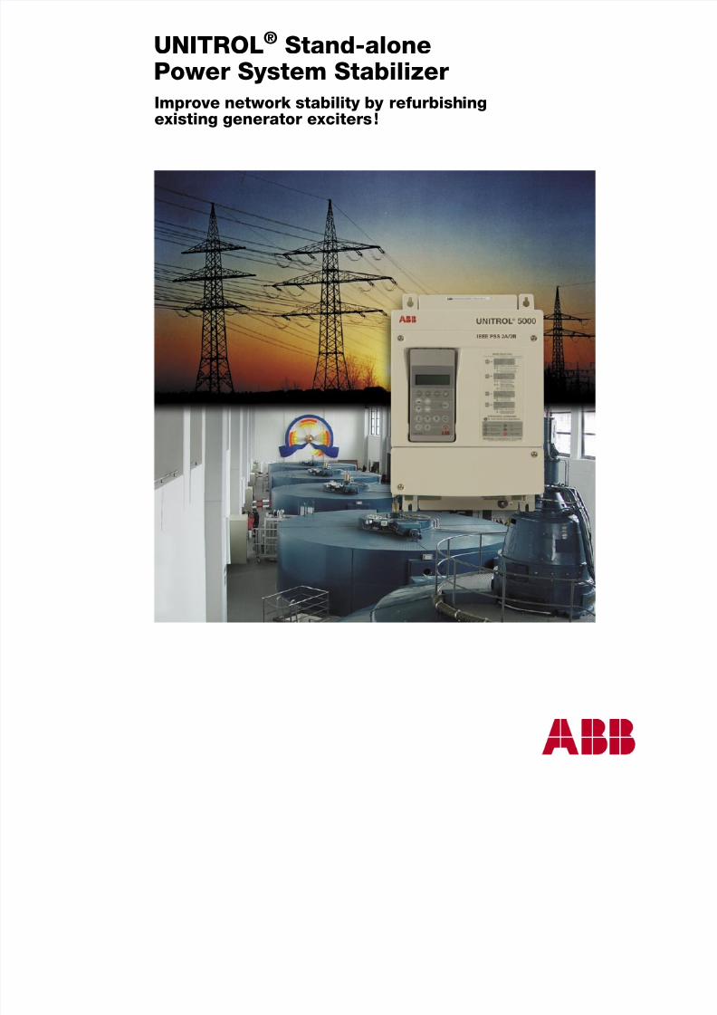
Improve network stability by refurbishingexisting generator exciters !
UNITROL® Stand-alonePower System Stabilizer
7/28/2019 AVR unitrol6080.pdf
http://slidepdf.com/reader/full/avr-unitrol6080pdf 2/4
2 ABB
Purpose and types of power system stabilizers
Causes and types of power oscillations
Network faults or network operation close to the sta-bility limits cause active power oscillations betweengenerators and the network. These electromechanical
oscillations of the rotor can be reduced by controlledinuence of the excitation current. Usually a distinctionis made between:
• Local oscillations between a generator and othergenerators in a power station. Typical oscillation fre-quency: 0.8 to 2.0 Hz
• Oscillations between neighboring power sta-
tions, typical oscillation frequency: 1.0 to 2.0 Hz
• Oscillations between network areas, each com-prising several generators. Typical oscillation fre-quency: 0.2 to 0.8 Hz
• Global oscillations, characterized by collective in-phase oscillations of all generators within a networkarea. Typical oscillation frequency: below 0.2 Hz.
The purpose of the power system stabilizer (PSS) is tomeasure these power oscillations and derive from thesea signal, which inuences the set point of the voltageregulator.
Increased reactive power consumption and
improved network stability
Nowadays, new excitation systems for medium-power
and high-power generators are almost always supplied with an integrated PSS. For existing power stations, where a complete replacement of the excitation systemsis not planned, there are good reasons to equip theexisting voltage regulators with PSS.
• Increasingly, network operators demand that thepower producers make an active contribution to net- work stability
• In many cases, this can increase the working range of the generator, especially in terms of reactive powerconsumption capacity
The ABB stand-alone PSS was specially developed forthese applications. This stabilizer is suitable for supple-menting not only ABB Automatic Voltage Regulators(AVR) / Static Excitation Systems (SES), but also those of the other manufacturers.
In the past, a wide range of different types of powersystem stabilizers was in use. Recently, there is anincreasing demand for types described below.
IEEE 2A/2B power system stabilizer
For most applications, a power system stabilizer, whichuses the algorithm in accordance with IEEE Standard421.5 PSS 2A/2B, is suitable. The electrical power Pe
and the rotor angular speed variation∆ω
are calculatedfrom the measured values for generator voltage andcurrent. In stationary operation, deviations in the electri-cal power are used to generate the optimum stabilizingsignal in terms of amplitude and phase relationship by means of a lead/lag lter. Without special measures, aPSS also reacts to changes in the turbine power. Thisundesired effect is suppressed by using the rotor angularspeed as an additional variable (determination of accel-eration power).
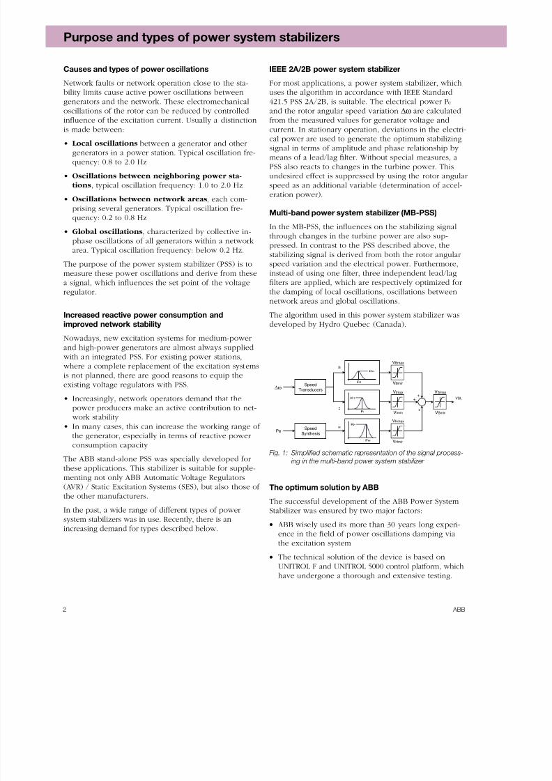
Multi-band power system stabilizer (MB-PSS)
In the MB-PSS, the inuences on the stabilizing signalthrough changes in the turbine power are also sup-pressed. In contrast to the PSS described above, thestabilizing signal is derived from both the rotor angularspeed variation and the electrical power. Furthermore,instead of using one lter, three independent lead/laglters are applied, which are respectively optimized forthe damping of local oscillations, oscillations betweennetwork areas and global oscillations.
The algorithm used in this power system stabilizer wasdeveloped by Hydro Quebec (Canada).
VBmax
VBmin
VImax
VImin
VHmax
VHmin
VSmax
VSmin
VSL
KB
FB
KI
FI
KH
FH
+
+
+
Speed
Transducers
Speed
Synthesis
B
I
H
Pe
∆ω
Fig. 1: Simplified schematic representation of the signal process-
ing in the multi-band power system stabilizer
The optimum solution by ABB
The successful development of the ABB Power SystemStabilizer was ensured by two major factors:
• ABB wisely used its more than 30 years long experi-ence in the eld of power oscillations damping viathe excitation system
• The technical solution of the device is based onUNITROL F and UNITROL 5000 control platform, which
have undergone a thorough and extensive testing.
7/28/2019 AVR unitrol6080.pdf
http://slidepdf.com/reader/full/avr-unitrol6080pdf 3/4
3 ABB
Simple integration into existing excitation systems
IG
UG
UG
IG
IE
out
CT
PT
UE
PSS
3
UNITROL PSS
UNS 4882
AVR
SES
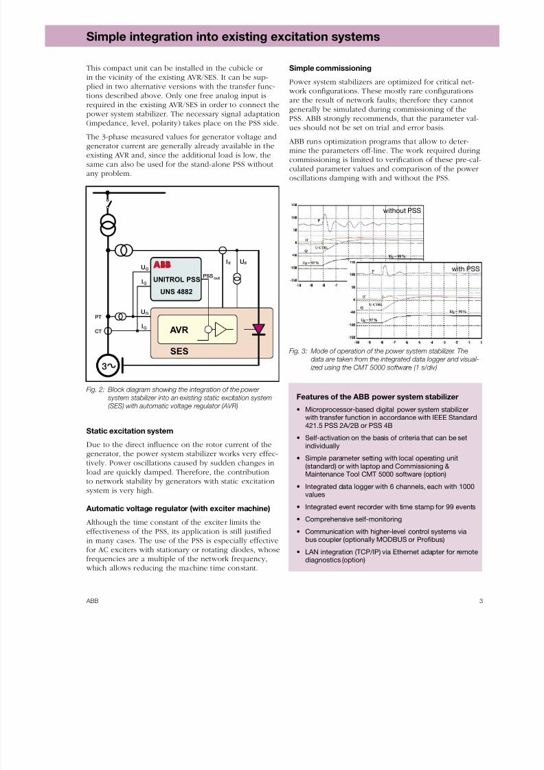
This compact unit can be installed in the cubicle orin the vicinity of the existing AVR/SES. It can be sup-plied in two alternative versions with the transfer func-tions described above. Only one free analog input isrequired in the existing AVR/SES in order to connect the
power system stabilizer. The necessary signal adaptation(impedance, level, polarity) takes place on the PSS side.
The 3-phase measured values for generator voltage andgenerator current are generally already available in theexisting AVR and, since the additional load is low, thesame can also be used for the stand-alone PSS withoutany problem.
Simple commissioning
Power system stabilizers are optimized for critical net- work congurations. These mostly rare congurationsare the result of network faults; therefore they cannot
generally be simulated during commissioning of thePSS. ABB strongly recommends, that the parameter val-ues should not be set on trial and error basis.
ABB runs optimization programs that allow to deter-mine the parameters off-line. The work required duringcommissioning is limited to verication of these pre-cal-culated parameter values and comparison of the poweroscillations damping with and without the PSS.
Fig. 2: Block diagram showing the integration of the power
system stabilizer into an existing static excitation system
(SES) with automatic voltage regulator (AVR)
Static excitation system
Due to the direct inuence on the rotor current of the
generator, the power system stabilizer works very effec-tively. Power oscillations caused by sudden changes inload are quickly damped. Therefore, the contributionto network stability by generators with static excitationsystem is very high.
Automatic voltage regulator (with exciter machine)
Although the time constant of the exciter limits theeffectiveness of the PSS, its application is still justiedin many cases. The use of the PSS is especially effectivefor AC exciters with stationary or rotating diodes, whosefrequencies are a multiple of the network frequency,
which allows reducing the machine time constant.
Fig. 3: Mode of operation of the power system stabilizer. The
data are taken from the integrated data logger and visual-
ized using the CMT 5000 software (1 s/div)
Features of the ABB power system stabilizer
• Microprocessor-based digital power system stabilizerwith transfer function in accordance with IEEE Standard421.5 PSS 2A/2B or PSS 4B
• Self-activation on the basis of criteria that can be setindividually
• Simple parameter setting with local operating unit(standard) or with laptop and Commissioning & Maintenance Tool CMT 5000 software (option)
• Integrated data logger with 6 channels, each with 1000values
• Integrated event recorder with time stamp for 99 events
• Comprehensive self-monitoring
• Communication with higher-level control systems viabus coupler (optionally MODBUS or Probus)
• LAN integration (TCP/IP) via Ethernet adapter for remotediagnostics (option)
without PSS
with PSS
7/28/2019 AVR unitrol6080.pdf
http://slidepdf.com/reader/full/avr-unitrol6080pdf 4/4
ABB Switzerland Ltd
Static Excitation Systems, Voltage Regulators
and Synchronizing Equipment
CH-5300 Turgi / Switzerland
Telephone: +41 58 589 24 86
Fax: +41 58 589 23 33
E-mail: [email protected]
Internet: www.abb.com/unitrol 3 B
H T 4 9 0 3 9 5 R 0 1 0 1
© C
o p y r i g h t 2 0 0 3 - 2 0 0 5 A B B .
A l l r i g h t s r e s e r v e d .
S p e c i f c a t i o n s s u b j e c t t o c h a n g e w i t h o u t n o t i c e .
4 2 0
195
R = 262
170
143
4 0 0
225
UNITROL
273
S I O
M U B
C O B
for screws M6
SPA
Panel
Signal terminalsTerminals
Technical data
Voltage supply
Supply voltage Us
24 V DC
Permissible voltage range 21.6 to 24.4 V
Current consumption 0.5 A
Power supply unit for other supply voltage Option
Inputs / outputs
Generator voltage input (3-phase)
Nominal voltage ( phase to phase) 100 to 110 to 120 V AC
Permissible voltage range: 0 to 1.5 p.u. 0 to 180 V AC
Nominal frequency 16 2 / 3 , 50, 60 Hz
Frequency range 10 to 120 Hz
Generator current input (3-phase)
Nominal current 1 A AC
/ 5 A AC
Permissible current range: 0 to 2.5 p.u. 2.5 / 12.5 A AC
Nominal frequency 16 2 / 3 , 50, 60 Hz
Frequency range 10 to 120 Hz Accuracy < 0.5 %
Analog input voltages
Nominal input voltage range Un
–10 to +10 V DC
Continuous permissible 1.5 × Un
Input resistance 220 kOhm
Nominal input current range In
–20 to +20 mA DC
Continuous permissible 1.5 × In
Digital inputs
Nominal input voltage 24 V DC
Input voltage range 20.5 to 28 V DC
Input voltage logical „0“ < 10 V DC
Input voltage logical „1“ > 18 V DC
Input current by 20.5 V 6 mA DC
±10 %
Analog output
Output voltage range ± 10 V
Output current ≤ 4 mA
Measuring transducer with galvanic separation Option
Relay output
Switching voltage AC/DC ≤ 250 V
Inrush current ≤ 16 A
Continuous current≤
2 A
Current-limited +24 V output
Nominal input voltage Us
24 V DC
Input voltage range 20.5 to 28 V DC
Output voltage Us
– 1 V
Maximum continuous current +24 V Out ≤ 40 mA
Environmental conditions
Permissible ambient temperature
Compliance with technical data 0 to + 55 °C
Operable 0 to + 70 °C
Storage temperature - 25 to + 85 °C
Mechanical stability
Vibration test according to IEC 60255-21-1
Response test, Class 2 2 to 150 Hz, a=2 gEndurance test, Class 2 2 to 150 Hz, a=2 gEarthquake test 2 to 35 Hz according to
IEC 60255-21-3, Class 2and IEEE Std. 344-1987 2 g in each axis
IEEE Standard 344-1987 5 g in each axis
Protection class
According to DIN 40050 IP 20
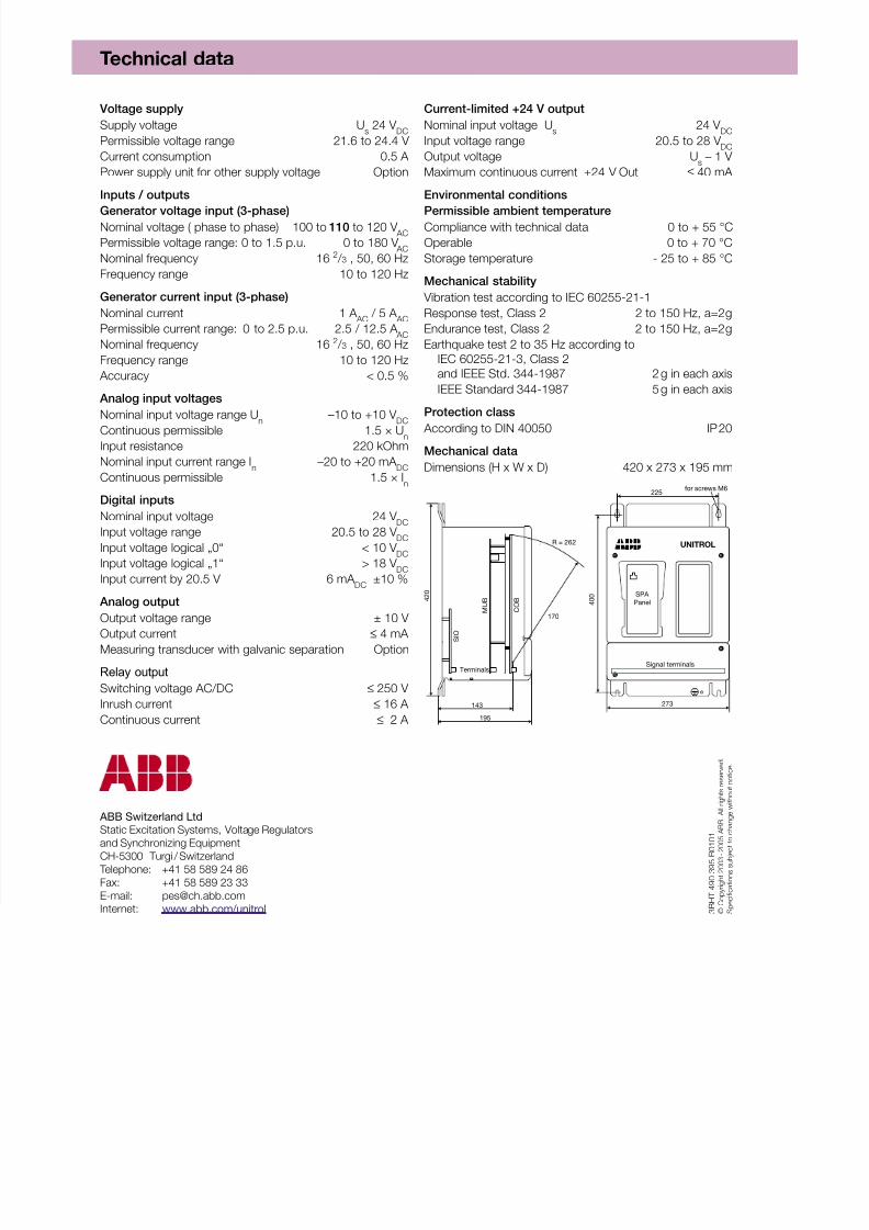
Mechanical data
Dimensions (H x W x D) 420 x 273 x 195 mm