A 3d geoscience information system framework - TU Freibergapelm/pub/3dgis-apel.pdf · comme par...
101
Institut National Polytechnique de Lorraine Ecole Supérieure de Géologie Ecole Doctorale RPPE A 3d geoscience information system framework THÈSE pour l´obtention du Doctorat de l´Institut National Polytechnique de Lorraine (Spécialité Géosciences) par Marcus Apel 4 octobre 2004
Transcript of A 3d geoscience information system framework - TU Freibergapelm/pub/3dgis-apel.pdf · comme par...
Institut National Polytechnique de Lorraine
Ecole Supérieure de Géologie Ecole Doctorale RPPE
A 3d geoscience information system framework
THÈSE
pour l´obtention du
Doctorat de l´Institut National Polytechnique de Lorraine
(Spécialité Géosciences)
par
Marcus Apel
4 octobre 2004
CONTENTS
1. Introduction . . . . . . . . . . . . . . . . . . . . . . . . . . . . . . 11.1 Research field ”3D Geoscience Information Systems” . . . . . . . 11.2 New aspects of 3d GIS functionality . . . . . . . . . . . . . . . . 21.3 Outline of this thesis . . . . . . . . . . . . . . . . . . . . . . . . 4
2. Requirements for a 3d geoscience information system . . . . . . . . . 52.1 Concepts and requirements for the data model . . . . . . . . . . . 52.2 Requirements for the geomodeling component . . . . . . . . . . . 102.3 Requirements for data exchange and data storage . . . . . . . . . 112.4 The role of queries in a 3d GIS . . . . . . . . . . . . . . . . . . . 13
3. Data modeling . . . . . . . . . . . . . . . . . . . . . . . . . . . . . 163.1 Introduction . . . . . . . . . . . . . . . . . . . . . . . . . . . . . 16
3.1.1 Representation of space . . . . . . . . . . . . . . . . . . 163.1.2 Object representation . . . . . . . . . . . . . . . . . . . . 19
3.1.2.1 Boundary representation (BRep) . . . . . . . . 193.1.2.2 Cellular models and generalized maps (GMaps) 243.1.2.3 Object representations in cellular volumes . . . 273.1.2.4 Polynomial geoobject representations . . . . . . 27
3.1.3 Regular 3d grid representation (Voxet) . . . . . . . . . . . 283.2 Synthesis of a new spatial-geological data model for 3d GIS . . . 29
3.2.1 Comparison of existing spatial geoobject representations . 293.2.2 The feasible solution: a Gocad- and GML-conform spa-
tial geological data model . . . . . . . . . . . . . . . . . 313.2.2.1 Spatial elements of the structural geomodel . . . 323.2.2.2 ObservationPoint data model . . . . . . . . . . 36
4. Spatial and non-spatial queries on geoobjects . . . . . . . . . . . . . 394.1 Classification and formalization of spatial query functions . . . . 394.2 Topological queries . . . . . . . . . . . . . . . . . . . . . . . . . 43

Contents iii
4.2.1 Theory of topological queries . . . . . . . . . . . . . . . 434.2.2 A concept of topological queries in 3d . . . . . . . . . . . 46
4.2.2.1 Queries based on the tessellation . . . . . . . . 464.2.2.2 Queries using explicit macro topology . . . . . 464.2.2.3 Queries using implicit macro topology . . . . . 484.2.2.4 Topological queries using volume models . . . 50
4.3 Geometrical queries . . . . . . . . . . . . . . . . . . . . . . . . . 514.3.1 Distance buffer queries . . . . . . . . . . . . . . . . . . . 524.3.2 Geometrical property queries . . . . . . . . . . . . . . . . 524.3.3 Orientation queries . . . . . . . . . . . . . . . . . . . . . 534.3.4 Relative location queries . . . . . . . . . . . . . . . . . . 55
4.4 Queries based on geological and numerical properties . . . . . . . 564.5 Geological queries using regular grid geomodels . . . . . . . . . 604.6 Combining a set of geomodels . . . . . . . . . . . . . . . . . . . 614.7 Query application - examples . . . . . . . . . . . . . . . . . . . . 62
4.7.1 Geomodel subset selecting . . . . . . . . . . . . . . . . . 624.7.2 Spatial and geological consistency checks . . . . . . . . . 62
4.8 Implementation features . . . . . . . . . . . . . . . . . . . . . . 64
5. Data management for 3d GIS - design and implementation . . . . . . 675.1 Introduction . . . . . . . . . . . . . . . . . . . . . . . . . . . . . 67
5.1.1 Summary of existing approaches to spatial geodata man-agement . . . . . . . . . . . . . . . . . . . . . . . . . . . 67
5.1.2 Spatial data in document centric object oriented databases - XML . . . . . . . . . . . . . . . . . . . . . . . . 68
5.2 A new concept of a generic XML/component-based 3d GIS . . . . 725.2.1 XQuery extension . . . . . . . . . . . . . . . . . . . . . 735.2.2 Design of the new data management system . . . . . . . . 755.2.3 XApp - applications to compute the result of XQuery re-
quests . . . . . . . . . . . . . . . . . . . . . . . . . . . . 795.3 Discussion . . . . . . . . . . . . . . . . . . . . . . . . . . . . . . 80
6. Conclusions . . . . . . . . . . . . . . . . . . . . . . . . . . . . . . 836.1 Critical reflections . . . . . . . . . . . . . . . . . . . . . . . . . . 846.2 Outlook . . . . . . . . . . . . . . . . . . . . . . . . . . . . . . . 86
Contents iv
Abstract
Two-dimensional geographical information systems are extensively used in thegeosciences to create and analyse maps. However, these systems are unable torepresent the Earth’s subsurface in three spatial dimensions. The objective of thisthesis is to overcome this deficiency and to provide a general framework for a 3dgeoscience information system (GIS) and to contribute to the public discussionabout the development of an infrastructure for geological observation data, 3d ge-omodels, and geoservices.Following the objective, the requirements for a 3d GIS are analysed. Accordingto the requirements, new geologically sensible query functionality for geometri-cal, topological and geological properties has been developed and the integrationof 3d geological modeling and data management system components in a genericframework has been accomplished. The 3d geoscience information system frame-work presented here is characterized by the following features:
• Storage of geological observation data and geomodels in a XML-databaseserver. According to a new data model, geological observation data can bereferenced by a set of geomodels.
• Functionality for querying observation data and 3d geomodels based ontheir 3d geometrical, topological, material, and geological properties weredeveloped and implemented as plug-in for a 3d geomodeling user applica-tion.
• For database queries, the standard XML query language has been extendedwith 3d spatial operators. The spatial database query operations are com-puted using a XML application server which has been developed for thisspecific purpose. This technology allows sophisticated 3d spatial and geo-logical database queries.
Using the developed methods, queries can be answered like:”Select all sand-stone horizons which are intersected by the faults A,B.”. This request contains atopological and a geological material parameter. The combination of queries withother GIS methods, like visual and statistical analysis, allows geoscientific inves-tigations in a novel 3d GIS environment.More generally, a 3d GIS enables geologists to read and understand a 3d digitalgeomodel analogously as they read a conventional 2d geological map.

Contents v
Resume
Les systemes d’information geographiques bidimensionnels sont tres utilisesdans domaine des Sciences de la Terre pour la creation et l’exploitation de cartes.Cependant, les GIS 2D ne permettent pas la representation tridimensionnelle dusous-sol geologique. Le but de cette these est de combler cette lacune et de creerles fondements pour un systeme d’information geographique 3D ainsi que deprendre part au debat publique sur le developpement d’infrastructures pour lesdonnees geologiques primaires, modeles geologiques 3D, et geoservices.Dans cette perspective, les exigences d’un systeme d’information geographique3D seront analysees. En reponsea ces exigences, des possibilites d’interrogationde proprietes geometriques, topologiques et geologiques ontete developpeeset une integration orientee composant des logiciels de geomodelisation et dessystemes de gestion des banques de donnees aete creee. Le cadre du systemed’information geographique presente ici est caracterise par leselements suivants:
• Enregistrement de donnees geologiques primaires et des geomodeles dansdes banques de donnees XML- compatibles. Sur la base d’un nouveaumodele de donnees, les donnees geologiques peuventetre referencees pardes geomodeles.
• Des fonctionnalites d’interrogation geometrique tridimensionnelle, topologiqueet geologique portant sur les geomodeles 3D et les donnees primaires ontete developpees et implementees.
• Le langage XML standard d’interrogation ”XQuery” pour interroger lesbases de donnees aete complete par l’ajout d’operateurs spatiaux. Lesoperations d’interrogation spatiale 3D sont calculees au moyen d’un serveurd’applications specialement developpe. Ce nouveau type de technologiepermet des interrogations spatiales et geologiques complexes sur les ban-ques de donnees.
Gracea ces methodes, des reponses aux interrogations 3D peuventetre apportees,comme par exemple:”s electionner tous les horizons de gres qui sont affectes parles failles A,B”. La combinaison d’interrogations avec d’autres methodes SIG,comme par exemple, les analyses visuelles ou statistiques, permettent des travauxgeologiques dans un nouveau cadre SIG. Dans un sens plus general, un SIG 3Dpermet aux geologues, de la meme facon que pour des cartes geologiques 2Dconventionnelles, de comprendre des modeles geologiques 3D.
Contents vi
Zusammenfassung
Zwei-dimensionale geowissenschaftliche Informationssysteme (2d GIS) werdenin den Geowissenschaften intensiv fur die Erstellung und Auswertung von Kartengenutzt. Jedoch vermogen es 2d GIS nicht, den geologischen Untergrund in dreiraumlichen Dimensionen (3d) darzustellen. Das Ziel dieser Dissertation ist es,diesen Mangel aufzuheben und den Rahmen fur ein 3d geowissenschaftlichesInformationssystem zu schaffen sowie zuroffentlichen Diskussionuber die En-twicklung einer Infrastruktur fur geologische Aufschlussdaten, 3d Geomodelle,und Geodienste beizutragen.Der Zielstellung folgend, werden zunachst die Anforderungen an ein 3d GISanalysiert. Entsprechend den Anforderungen wurden geologisch sensitiveAbfragemoglichkeiten an geometrischen, topologischen und geologischenEigenschaften entwickelt und die komponenten-orientierte Integration von3d Geomodellierungs-Software und Datenbank-Managementsystem geschaffen.Das vorgestellte geowissenschaftliche Informationssystems-Framework ist durchdie folgenden Merkmale charakterisiert:
• Speicherung von geologischen Aufschlussdaten und Geomodellen in XML-fahigen Datenbanken. Entsprechend einem neu entwickelten Datenmodellkonnen geologische Daten von Geomodellen referenziert werden.
• 3d geometrische, topologische und geologische Abfragefunktionalitaten anGeomodellen und Aufschlussdaten wurden entwickelt und als Plug-in fureine 3d Geomodellierungs-Software implementiert.
• Fur Datenbank-Abfragen wurde die XML Standard-AbfragespracheXQuery um raumliche Operatoren erweitert. 3d raumliche Abfrageopera-tionen werden mit Hilfe eines speziell entwickelten Applikations-Serversberechnet. Diese neuartige Technologie erlaubt komplexe 3d raumlicheund geologische Datenbankabfragen.
Mit den entwickelten Methoden konnen 3d Abfragen beantwortet werden,wie zum Beispiel: ”Selektiere alle Sandstein-Schichten die von den StorungenA,B geschnitten werden.”. Die Kombination von Abfragen mit anderen GIS-Methoden, wie beispielsweise visueller und statistischer Analyse, erlaubtgeowissenschaftliches Arbeiten in einer neuartigen 3d GIS-Umgebung. Imallgemeineren Sinn ermoglicht ein 3d GIS Geowissenschaftlern digitale 3dGeomodelle analog zu konventionellen 2d geologischen Karten zu verstehen.

Contents vii
Acknowledgements
This research project has been funded by the Robert-Bosch-Foundation, theDeutsche Forschungsgemeinschaft, and the Association Scientifique pour laGeologie et ses Applications. Thanks to all who contributed financially and madethis thesis possible.
During this research project, many scientists and colleagues shared their thoughtswith me, and inspired and motivated me. Especially I wish to mention here Prof.Dr. Gerald van den Boogaart, Dr. Guillaume Caumon, Dr. Olivier Grosse, Dr.Eric de Kemp, Dr. Uwe Kroner, Dr. Bruno Levy, Thomas Jerome, and Dr. SophieViseur. I am grateful to the whole Gocad Research Group in Nancy who sharedtheir knowledge of geomodeling with me and provided a pleasant atmosphere.Not just cooperating scientists but also staff is essential to cope with daily tasksand bureaucracy. Thus I wish to thank Madame Cugurno, Frau Klocke and FrauSchmiedgen for their reliable, thoughtful work.
Particularly I owe thanks to Tobias Frank for his very constructive collabo-ration. He helped significantly to realize my ideas concerning the XML-basedgeodata management. I hope that our collaboration and friendship will persist,and wish him all the best for his thesis project with the Gocad Research Group.
The manuscript of this thesis owes many improvements to the remarks of itsproof-readers. I wish to thank Dr. Jens Richter, Prof. Dr. Jean-Laurent Malletand Prof. Dr. Helmut Schaeben for their efforts and valuable time.
Prof. Dr. Jean-Laurent Mallet leads the Gocad Research Group, and withhis ideas and generous support he opened a treasure of resources for me. Withouthim, Gocad and thereby one fundamental basis of this work would not exist. Ithank him very much for the supervision of this thesis and the great chance tospend one year with his research group.
Finally, I wish to give special thanks to Prof. Dr. Helmut Schaeben. Hehas provided the initial idea for this research project, and as supervisor he has in-spired me to accomplish far more than I ever expected. Without his influence, thisthesis and my graduate school experience would have unfolded quite differently.I am, and will remain, appreciative of his generosity and support.

1. INTRODUCTION
1.1 Research field ”3D Geoscience Information Systems”
Geosciences investigate the Earth which is a spatially three-dimensional (3d) ob-ject and evolves through time. Two-dimensional (2d) maps have been the ma-jor means of communication between geoscientists ever since the origin of geo-sciences. The introduction of geographical information systems into the geo-sciences facilitated the creation and the interpretation of 2d maps by techniquesof information technology. In geology, 2d geoscience information systems (ab-breviated ”GIS” in this thesis) consisting of an user application environment anda database management system (DBMS) are extensively used to create, manage,query, and analyze georeferenced maps [7]. GIS provide a means to generateabstract models of real world geological situations based on data. FollowingBonham-Carter [7], there are five core activities of current 2d GIS that can beapplied in geoscience applications:
1. Data managementis done in a database according to a spatially referenceddata model. Data of heterogeneous source, type, and confidence are to becompiled and stored. Geoservices allow to share information between geo-scientists.
2. Data visualization: GIS facilitate the creation of 2d data views, map models,and the visual inspection of spatial patterns.
3. Combinedspatial and nonspatial queryingis possible because links be-tween spatial features and associated nonspatial feature attributes in a rela-tional database are maintained.
4. Data analysisis achieved through combining different map layers and ex-amining them simultaneously to discover their relationships.
5. Prediction supports decision making based on multiple factors of spatialinformation. Knowledge-driven and data driven methods using Bayesian
1. Introduction 2
models have been used to predict mineral potentials [7].
During the last decades a steep increase of acquired digital geoscience datacould be observed. This is mostly due to the usage of efficient new methods.Examples are geophysical methods like ground penetrating radar and 3d seismicsurveys, remote sensing, geochemical methods like micro-probing, age determi-nation methods like fission track analysis, and digital field mapping techniques[11]. Continuing developments suggest that this trend will in future rather in-crease than stagnate. The issue to manage, process and interpret these data resultsin the usage of GIS in the geosciences.In GIS, geological objects are commonly represented as map objects in two spa-tial dimensions. While real geological objects are essentially referenced in 3-dimensional space, a 2d map represents a cross-section through a 3d geologicalspace. ”Spatial” extensions of common 2d GIS are at present not applicable for3d geological applications as they are not capable of representing 3d spatial ge-ological relationships and properties with 3d spatial variation. 2d GIS representthe altitude valuesz of geoobjects as a continuous function of the geographicalcoordinates:z= f(x,y). That way they cannot model 3d geological objects whichhave multiplez-values for a singlex,y-value. On the other hand, 3d geomodelingsoftware provides data models and functionality to represent geological situationsin 3 spatial dimensions as geomodels.Geomodeling systems are widely applied in the petroleum and mining explorationindustry, geological surveys, and academic science departments. Gocad v.2 ([34],Earth Decision Sciences, Houston/TX) is one of the most evolved geomodel-ing environments available. Based on the unique discrete smooth interpolationmethod [34], Gocad allows to build sophisticated structural models honouringheterogeneous input data. It facilitates 3d geomodeling in a unified, geoobject-oriented way and also provides advanced 3d visualization, material property mod-eling. Thus Gocad can be seen as a core 3d GIS user application.
1.2 New aspects of 3d GIS functionality
The increase of digital geodata and the possibility to create regional 3d geomodelsresults in new, specific needs for geodata management, and extended possibili-ties for geodata query and analysis. However, both fields are underdeveloped inexisting 3d geomodeling environments. This becomes obvious especially whencomparing geomodeling software with evolved 2d GIS.

1. Introduction 3
Geodata management. Current 2d GIS provide specific solutions for data man-agement of 2d raster and vector data in relational databases. Recent developmentsfocus on interoperability and the usage of standards. The OpenGIS Consortium(www.opengis.org) of GIS vendors and institutions is developing standards forgeodata exchange, like the GML data model [22]. This can be a starting point forinteroperability between 2d GIS databases and 3d geomodeling software.On the other hand, no appropriate solution for unified storage and query of ge-ological observation data and 3d geomodels exist to date. The available sys-tems including Gocad, Petrel (Schlumberger IS, Houston/TX), and EarthVision(Dynamic Graphics, Alameda/CA) offer solely file-based storage of geomodels.Past attempts to develop database-supported 3d GIS resulted in systems dedicatedto a specific database system with non-standard interfaces. It is likely that the”GeoToolKit” 3d GIS [10], which is based on an object-database and CORBA, isnot being used in practice due to these insufficiencies.While 2d GIS applications are commonly coupled with database servers for stor-age, available 3d geomodeling software products still use a file-based data storage.This has several drawbacks, for example:
• the access to large datasets is difficult because no query functionality exists,
• no consistent multi-user access exists, and
• the data safety is low compared with database management systems(DBMS).
In order to improve these deficiencies, a change from a file-based data storage toa networked database server is required. From these arguments the necessity todevelop a new data management system for 3d GIS data can be deduced.
Demand for new query facilities. Geomodeling software like allows to build andvisualize 3d geomodels of geological situations including their structures and ma-terial properties. In addition, the software Gocad comprises extensive capabilitiesfor geodata analysis based on multivariate statistics and geostatistics.However, the existing functions are not appropriate for sensible geological andspatial queries. Geometrical and attribute queries belong to the core functional-ity of 2d GIS. One primary concern of this thesis is to develop query methodsbased on geological, geometrical and topological properties and relationships in3d space which is impossible in 2d GIS. The investigation of 3d models of largeand complex geological situations using queries may lead to new insights and may
1. Introduction 4
allow the systematic search of exploration targets.Due to their complexity and high level of user interaction, statistical data anal-ysis should not be considered as part of the query language. Instead, it may beused separately within a geomodeling application as an expert user component ofa GIS.
1.3 Outline of this thesis
The objective of this thesis is to overcome the existing shortcomings related to thedata management and geologically sensible query functions in 3d geomodelingsystems, and to provide a general framework for a 3d geoscientific informationsystem. This work shall also be a contribution to the public discussion aboutthe development of an infrastructure for geodata, geomodels, and geoservices.Several research fields of a 3d GIS are examined: data model, query functionality,and data management. Accordingly, this thesis is subdivided as follows:
1. Analysis of the user requirements with respect to the data model, geomod-eling functionalities, and data management (chapter 2).
2. Design of a data model based on the user requirements and under consider-ation of geomodeling software constraints (chapter 3.2).
3. Design of GIS-specific user application functionality; especially for spatialand geological queries (chapter 4). These can be used with an existing 3dgeomodeling software in a plug-in technique.
4. Design of a geodata management system incorporating a database serverand development of spatial database query functionalities (chapter 5).
Each chapter will have a separate introduction. The developed concepts are sup-ported by a prototypical implementation and by testing the system componentsusing available data. Within this work the creation of a complete 3d GIS systemwith hundreds of user commands comparable to a mature 2d GIS is impossible.Therefore, the core functionality will be designed and implemented in a generic,standards-oriented and extensible framework.

2. REQUIREMENTS FOR A 3D GEOSCIENCEINFORMATION SYSTEM
2.1 Concepts and requirements for the data model
The geological knowledge generally accumulates starting from data available asmeasurements and observations. Measurements and observations are interpretedand set in context to comprise information. Geological concepts, human thoughtand intuition often extend this information by ideas. For a geoscience informationsystem it is crucial to represent knowledge in an appropriately approximated andcomprehensive way. A data model is formally defined as a set of fundamentalconceptual objects and mathematical and logical rules that govern their behaviour.The careful choice of the conceptual objects and their relationships is the key toan intelligible and complete computer representation of geological knowledge.The following paragraphs describe the requirements for a geological 3d GIS datamodel.
Related works. Several data models exist to represent geological field observa-tions and map data in relational data bases, the most advanced and complete ofwhich are the NADM [40] and the NATMAP [12] data models. These models arenot designed to represent geological objects including their spatial relationshipsin three spatial dimensions, but are focused on geological observations and 2dmaps. The NADM includes a data model for geological concepts. This can beused as a basis for a data model for geological observations.Different from those approaches, the OpenGIS consortium (www.opengis.org)created a data model for the representation of geographical data using angeoobject-centric view.
From observations to models. A data model for geological data need to accountfor both observed data and modeled data. Observed data are only available ata finite set of points in 3d space. Observational data captured by geologists in

2. Requirements for a 3d geoscience information system 6
the field are commonly stored in a field book and include qualitative descriptionsof the petrographic composition, indicators of stratigraphic facies and age likefossils, fabric and structural descriptions and measurements, drawings, images,and meta-data of sampling locations. Often, samples are being examined in alaboratory and age data and quantitative geochemical and petrophysical data areobtained.Spatial models are derived by spatial interpolation of data observed at points andcan represent geological situations in 3d space. To create a digital geologicalmodel using the object-oriented approach, the subsurface space has to be dis-cretized into homogeneous regions based on a chosen parameter. Examples forcommonly used parameters are the petrographic composition, the stratigraphicage, or tectonic structures. The choice of the parameters and the classificationinto subsets is done by a geologist according to the geomodeling project motiva-tion. This may lead to different models which are created by inversion from asingle data set, but with a different parameterization.
Geoobject. In computer science, the standard method to model the propertiesand behaviour of conceptual entities is the object-oriented approach. Geoob-jects are mappings of spatial entities of the Earth subsurface to abstract computerobjects. Commonly, geoobjects are inferred in an iterative and scale dependentway from observational data: evidence is collected and hypotheses are formulatedwhich are either supported or refused by further evidence. In that context, geoob-jects are evolving and mutable abstractions which aid in the analytical process ofgeological interpretation by means of a GIS.By definition, an object consists of a set of variables and methods which defineits properties and behaviour, respectively. A geoobject is characterized by one ormore parameters which are constant or vary within an interval at each of its spatialpoints. These parameters constitute the geoobject definition criteria.A geoobject is composed of a name, a spatial description including geometry andtopology, and a thematic description including geological or numerical proper-ties. Numerical properties are scalar or vector variables which may be defined forevery point in space in a discrete way, or globally. Geological properties can bedefined for a geoobject and may include alphanumeric descriptions, for examplethe lithological or structural classification of a geoobject.A different geospatial data model has been developed by the geographic informa-tion system community. The OpenGIS data model [22] uses meta-data to qualifyspatial features. No inherent distinction between observed facts and concepts is

2. Requirements for a 3d geoscience information system 7
made. Thereby it intends to represent the real world in a static way, while mod-els are merely treated as meta-data. In geology, this approach is problematic asthe geoobjects are commonly not static but change according to the geologists’knowledge based on observations and concepts.In geology, models can be inferred from observations via a description based onconcepts, as depicted in figure 2.1. Here, observation points are associated withproperty descriptions containing any geological data, knowledge, and assumptionsderived from the observation points. Property descriptions are based on concep-tual geological models, like stratigraphy or structural evolution. Also based ongeological concepts, a set of geoobjects can be defined. Geoobjects representnamed geological entities of the Earth crust with spatial and thematic property de-scriptions. These are in turn associated with the observation points. A geological3d GIS needs to represent all components of knowledge related to geoobjects andobservations.The value of the parameter which leads to the subdivision of the subsurface intoa set of geoobjects is not accurately known at any point in space. For example,the probability p that the lithology is homogeneous within a fixed spatial regionis always p<1. This is due to the fact that often models are based on sparse inputdata and a vague geological concept. Moreover, a problem of GIS systems repre-senting geoobjects by their boundaries is that they cannot account for fuzzy spatialtransition zones between geoobjects. A promising approach to quantify uncertain-ties is a continuous geoobject representation with 3d grids. Here, a membershipfunction property can be assigned to the cells. This membership function can, forexample, be computed by multi probability field simulation [28].
Geomodel. A geomodel is an abstract digital representation of a part of the Earthsubsurface. Two main discrete approaches exist to partition the space into a setof mutually exclusive and collectively exhaustive volumes: geoobject-based mod-els and regular grid models. In practice, a complete geomodel comprises botha unique structural model representing the topology and geometry of the subsur-face geoobjects (figure 2.2 shows an example), and a property model providing amechanism to model the material properties of each geoobject.For discrete spatial property modeling, regular grids are commonly used. Thismethod allows to integrate all available information into one model. Using a mem-bership function, it is possible to model the spatial extension of geoobjects. Majordrawbacks are the non-existence of explicit topology and topological conceptslike boundary, which, for example, allows the concise representation of faults.

2. Requirements for a 3d geoscience information system 8
ConceptModelSpatialModel
ObservationPoint
GeoObject
GeoModel
PropertyDescription
Fig. 2.1: UML diagram of the top-level conceptual data model. Geoobjects are in-ferred from observations by concepts. Edges denote association, diamonds denoteaggregation.
The combination of structural and property geomodels incorporating all avail-able information related to its constituting geoobjects, is also called ”shared Earthmodel” [20].In general, it can be stated that representing geoobjects solely by their boundariesis sufficient if the structural geological situation is of primary interest, or if avail-able material property data are too sparse to build a property model. This is oftenthe case for regional geological mapping campaigns, and during the initial state oflocal geomodeling projects. This work is mainly concerned with the developmentof GIS-functionalities for geoobject-based models.
Topology. A space can be abstracted as a set of points. Topology adds a struc-ture to these points by defining neighbourhood in a qualitive way: each point inthe space knows which points are in its neighbourhood. Geometry and topologyrelate to each other like absolute and relative location. In chapter 3.1.1 a formalintroduction to topology is given. Using a topological model the geological spacecan be partitioned into subsets representing geoobjects. Geoscientific queries areoften topological, and it chapter 3.1.1 of this thesis will show how it is possibleto answer them efficiently by focusing on the topology of the space, and not itsgeometry. For query purposes in a GIS, the macro topology is of particular in-terest as it describes relationships between the geological objects of a geomodel.A topological model can be helpful to check the consistency of the spatial modelwith geological concepts, to explore the spatial geoobject relationships, or to se-

2. Requirements for a 3d geoscience information system 9
Fig. 2.2: Example of a boundary representation geomodel showing the Erzge-birge region/ Germany. This large-scale crustal model is based on geological andgeophysical data and has been created using Gocad software. To examine suchregional models, spatial and geological query functionality is required.
lect subsets of a set of objects using specific topological criteria.Topology is implicitly contained in the geometric description of a geomodel, butit can also be stored explicitly. If stored explicitly, fast combinatorial algorithmscan be used instead of computational geometry. The separate representation ofthe geometry and the topology of geoobjects provides the foundation for efficienttopological query functions which are based on algorithms with linear complexity.
Geometry. The geometry defines the absolute spatial reference of geomodel ob-jects in a coordinate reference system in 3-dimensional euclidean metric space.Since we have to map spatially continuous geological situations to a computerrepresentation, the geometry has to be approximated with finite numbers. For itsrelative computational simplicity and common usage in the geosciences a localcartesian coordinate reference system is preferred.
Geological properties. The semantic description and other non-spatial propertiesof geomodel objects and their composite elements constitute the geological prop-erties. The set of properties depends on the project purpose. The core geological
2. Requirements for a 3d geoscience information system 10
properties which can be associated with a spatial model include:
1. Material composition. This can be described, for example, by chemicalconstituents or a classified rock type name. The composition may changeas a function of geological time.
2. Time of genetic events, and genesis processes. The time interval of genesismay also be described by a classified stratigraphic name.
3. Structures, strain, strain rate, stress field, temperature. For metamorphicrocks these properties are commonly represented by a function in the stress-temperature-time domain.
4. Physical parameters derived from direct measurements, and geophysicalmodels.
In common GIS, properties of simple data types are stored in a relational attributedatabase. In a 3d geological GIS, properties of different data type need to be de-fined for the micro- and macro topological elements such as nodes or surfaces. Forgeological objects, a wide range of simple data types (for example floating pointnumbers, strings, binary images) and complex data types (for example a semi-structured sample point description, functions) need to be stored as properties.
2.2 Requirements for the geomodeling component
A geoscience information system essentially needs a full-featured geomodelingfront-end. For such, the following features are required in particular:
1. a data model for geomodels which allows to represent the topology, geom-etry and material properties of geoobjects
2. functionality to build sophisticated structural models which honour hetero-geneous input data
3. possibility to update a geomodel by re-interpolation, if new input data needto be honoured
4. 3d visualization
5. property modeling functionality including advanced geostatistical methods

2. Requirements for a 3d geoscience information system 11
These requirements are met by currently available systems. One of the mostwidely used and evolved 3d geomodeling applications is Gocad (Earth DecisionSciences, Houston/TX). Gocad facilitates 3d geomodeling in a unified, geoobject-oriented way. Its geomodeling capabilities are largely based on the unique discretesmooth interpolation method [34]. A large set of application objects for geomod-eling is available: point sets, lines, surfaces, topological boundary models, andirregular and regular grids. Gocad can be seen as a core 3d GIS user application.
2.3 Requirements for data exchange and data storage
Storage and exchange of geospatial data between databases and different front-ends like 3d geomodelers, GIS or internet browsers require a format which is ca-pable to represent instances of geomodels and geological observations. By the useof standardized data models and formats a minimum loss of information duringdata transfer and minimum interface development efforts can be ensured.
Data exchange using XML. XML is a mark-up language for documents con-taining structured information. Structured information contain both content (text,graphics, equations, etc.) and an indication of the semantics of that content. Amark-up language is a mechanism to identify structures in a document. The XMLspecification defines a standard way to add markup to documents.During the last years, XML [49] was adopted as the standard mark-up languagefor data interchange by the ISO, the W3C (www.w3.org), and the OpenGIS con-sortium (www.opengis.org). Based on XML, the data definition language XMLSchema, the comprehensive query language XQuery, and mature tools like parsersand DBMS for the storage of XML documents evolved. An XML Schema isa valid XML document which uses object oriented features in order to definedata models for XML-formatted document exchange and database storage. Thesefeatures include inheritance from existing data types by restriction or extension,complex data types, referencing, and name spaces. The ”OpenGIS Consortium”of GIS companies and user groups created specifications for geographical dataexchange and a XML Schema named ”Geographical Mark-up Language” [22].During discussions with potential users of a 3d GIS it became clear that the numer-ous requirements could be realized only with a XML based system. Argumentsfor geodata management based on XML are:
• suitable for both highly structured data like matrices, and semi-structured
2. Requirements for a 3d geoscience information system 12
data like a textual observation description
• possibility to define object-oriented data models
• long-term usability is provided as the documents can be stored in human-readable self-describing text format
• vendor neutral, platform independent, ISO standardized format; XML stan-dards are free available and widely used
• straightforward creation and maintenance of XML schemas. These can eas-ily be adapted or extended for specific, customized applications
• usable by different geoscience front-ends:
– authoring applications like geomodelers, GIS, field mapping software
– viewing applications like internet browser using X3D format
– storage applications like XML-capable DBMS, file system
• available mature libraries provide programming interfaces for fast applica-tion development
• comprehensive, extensible query language ”XQuery” [48] is available
A disadvantage is the need for relatively large storage capacities, which are how-ever not a limiting factor. For example, very large XML databases are success-fully being used for mission-critical business and logistics projects by numerouscompanies and agencies [18]. As a future alternative for highly structured datathe recently planned binary XML variant by the World Wide Web consortium(www.w3.org) should be considered. This format is especially applicable for datawith large storage needs, like high-resolution images and 3d grids.
Data storage and data serving. Specific spatial databaseinterfaces exist forsome 2d GIS like ArcGIS. These are however not appropriate for 3d geoobjects,because the data model is very different and the representation of 3d hierarchicaltopological models is not supported. Also, semi-structural geological data likeobservation point descriptions and complex geomodels with hierarchical topol-ogy are difficult and time-consuming to map to relational structures. Moreover,

2. Requirements for a 3d geoscience information system 13
the object-oriented character of the data gets lost when geoobjects and observa-tions are distributed over a large set of tables. This can be avoided when XML-supporting databases are used. The 3d GIS proposed in this thesis should have aDBMS-based data management with the following features:
1. client-server architecture, where geomodeling applications act as clients ofa database server
2. consistent multi-user access via IP network
3. support for XML and XML Schema
4. XML query language for data access, including geometrical and topologicaloperators
5. high data safety
The coupling of a professional 3d geomodeling software and a DBMS can providea 3d geoscience information system offering comprehensive spatial and geologicalquery capabilities.
2.4 The role of queries in a 3d GIS
Peculiarities. Querying geographically referenced geoscience data (geodata) isan essential aspect of a GIS. If one considers non-spatial properties of geodata,several generic data mining tools apply to geodata analysis:
• descriptive statistics, infering multivariate statistics,
• linked map and graph displays, and other visualization tools ,
• association rules detection, sequence discovery,
• predictions using neural networks and memory based reasoning.
These tools are available in several data mining and statistical analysis softwarepackages. However, due to special characteristics of geoinformation, generic non-spatial queries often provide not satisfying results, while queries for spatial prop-erties and relationships are of high interest in geosciences. Particular features ofgeological information which need to be accounted for by a GIS include:

2. Requirements for a 3d geoscience information system 14
• Data are referenced in 3d euclidean space. Complex spatial relationshipsoccur.
• Data are referenced in a geological time scale. For the sake of simplicity,geological time can be treated as a scalar property of observation data andgeomodel objects. A time-dependent representation of geodata would resultin a spatio-temporal GIS.
• Spatial objects can be defined using different classification parameters, forexample composition, stratigraphic age, or structure.
• Complex spatial-temporal-property data interactions occur.
• Data uncertainty is often spatially structured; standard statistical methodsare thus seldom helpful. Non-stationarity may occur.
A 3d GIS should provide a means to pose both spatial and geological propertyqueries. Such functionality need to be available both within the geomodeling userfront-end and at the DBMS. If required, specialized non-spatial data mining andstatistical softwares may be integrated with the GIS in an open, component basedenvironment.The queries important for geological purposes are based on the topology, geome-try, and non-spatial properties of geomodel objects. Spatial and non-spatial queryoperators can be combined with logic expressions to define a comprehensive querylanguage. Applications of such a query language are to select sub-sets, to applyspatial functions, to check the consistency of the geological model, or to obtainproperty information.
Geological consistency checks. If one creates a geomodel, it may not be spa-tially or geologically sound due to insufficient, inaccurate or imprecise input data,inaccurate geological concepts, or inappropriate geomodeling methods. Also ifwe add new data to a model, a geomodel may become inconsistent. Such in-consistencies can be detected by checks which make use of a combination of thetopological, geometrical, and semantical properties of geoobjects.For example, if the result of the query:”Select all fault surfaces of Permian agewhich intersect Cretaceous horizons.”is not an empty set, then either i) the age ofat least one object is wrong, ii) the geometry of at least one object is wrong, or iii)the geological interpretation of at least one object is wrong (for example, the faultas such is a misinterpretation).
2. Requirements for a 3d geoscience information system 15
Selection. Selection is particularly required to constrain mining exploration tar-gets or environmental damages. Such queries are set-theoretic selections whichmay contain spatial parameters. The query with thenon-spatial condition ”Selectall cells of a set of geoobjects with a geochemical anomaly A.”gives a set of cellsas result. This set of cells comprises a new spatial region. Selection queries mayuse geometrical, topological, and geological properties of geoobjects. When thesource of an ore deposit, or endangered regions nearby a waste dump are of inter-est,spatial conditionsneed to be added to the query parameters. For example, thequery”Select all fault surfaces which are closer than distance d to the geochemi-cal anomaly A.”can give clues about the ore source of a deposit, or ground watercontamination from a waste dump which is situated above a fault aquifer. Selec-tion queries can also be used to detect geological or spatial relationships betweengeoobjects.To illustrate possible spatial queries in a GIS, here are some further examples:
• ”Select the set of fault surfaces with given mean normal direction AND agiven geochemical anomaly within a certain distance.”This query may beused for exploration sensitivity studies for hydrothermal ore deposits.
• ”Select the set of geoobjects with a certain permeability AND which havegiven faults as their boundaries.”This type of query can aid in the under-standing of fluid movements.
• ”Select the sets of geoobjects which occur in a given stratigraphic succes-sion.” This can be used to detect stratigraphic patterns.
Property queries. Queries for properties do not select any geoobjects, but returnproperty values of these. Properties can be stored in the database and queried theredirectly, like a query”Return the stratigraphic age value of geoobject A.”, or canbe computed within an application from other properties. An example for sucha property is the euclidean distance between two points, which can be computedfrom the geometry. Such queries need to be answered by user applications and arenot directly required for database requests.
3. DATA MODELING
Special features of geological data are their 3d spatial reference. How can spatialdata like geoobjects be stored in computers? Geoobjects cannot be representedin a computer directly, as the amount of data required would be infinite. Instead,real world geoobjects have to be approximated and abstracted. The way of rep-resenting geoobjects is a very important aspect of a GIS and essentially influ-ences the geomodeling functionality and the query possibilities. The approachesto model geoobjects can be grouped intogeoobject-oriented representationsandregular grid representations(also namedfield- or raster representations). Whendiscussing spatial data models, the following parameters have to be optimized:
• accurate and precise representation of real geoobjects including their geo-logical semantics
• computational efficiency and numerical robustness
• representation of geometry and topology
In the following sections the spatial and geological data representations whichare being used in current geomodeling systems and geological databases will beinvestigated for their application in a geoscience information system. Then a datamodel will be chosen for observational data and geomodels, and formulated usingthe standardized Unified Modeling Language (UML, [44]), and XML.
3.1 Introduction
3.1.1 Representation of space
Point set topology. Geological matter can abstractly be regarded as sets ofpoints on which set-theoretic operators can act and functions and relations maybe defined. Topology is the mathematical study of properties of objects which arepreserved through deformations, twistings, and stretchings. Point set topology,

3. Data modeling 17
also called set-theoretic topology or general topology, is the study of the neigh-bourhood properties of sets. Sets can thereby be endowed with structure.The definitions in this section are taken from Goldberg and Bishop [6] andMunkres [35]. Formally, a topology on a point setX is a subsetT⊆2X thatsatisfies the following conditions:
• the empty set andX are inT,
• T is closed under arbitrary unions, and
• T is closed under finite intersections.
A topological spaceis a setX with a topologyT on X. The sets in a topology onX are calledopen sets, and their complements inX are calledclosed sets. Theinterior A of a setA⊆X is the union of all open sets contained inA. TheclosureA of a setA⊆X is the intersection of all closed sets containingA. Theboundaryofa setA is δA = A - A.Two spaces arehomeomorphicif they can be deformed into each other by a con-tinuous, invertible mapping.Manifoldsare defined to be sets such that the neigh-bourhoods at all of their points are homeomorphic to a disk.In geomodeling, surfaces play an important role as they concisely allow to definethe spatial extent of geoobjects and structures. In a point set theoretical notion,surfaces are compact and connected spaces with the following property: Eachpoint of a surface has a neighbourhood homeomorphic to either the planeR2, orthe half-planeH2. Points of the first type are called interior points, and those of thesecond type are called boundary points. The set of all boundary points constitutesthe boundary of the surface. It consists of one or more boundary components,each of which is homeomorphic to a circle. If the surface has no boundary, it iscalled a closed surface.
Algebraic topology. Algebraic topology is the study of algebraic objects at-tached to topological spaces. Combinatorial topology is a special branch of al-gebraic topology that uses combinatorial methods. The explicit representation oftopology in a computer data structure is possible by combinatorial topology meth-ods which decompose a complexn-manifold object into a set of elementary cells.In 3d geomodeling two main approaches can be distinguished to represent thespatial extension of geoobjects:
• cellular models, and

3. Data modeling 18
• boundary representation models.
Cell complexes. An (open) n-cell is a topological space homeomorphic to anopen ballEn of Rn. ForR3 are important cells:
• a 0-cell, called ”vertex”, is an isolated point
• a 1-cell, called ”edge”, is a simply connected curve without ending points
• a 2-cell, called ”face”, is a simply connected open surface without border
• a 3-cell, called ”volume”, is a simply connected solid without (closed) bor-der surface.
A cell complex is a setK of cells inRn satisfying two conditions:
• Every face of a cell is a cell inK)
• If P andP’ are cells, then their intersection is a common face of both.
The body|K| of a complexK is the union of all cells. Geomodels based on cellcomplexes will be discussed in the context of GMaps in section 3.1.2.2.
Simplicial complexes. A simplex is an elementary geometric building block in agiven dimension: a 0-simplex is a point (node), a 1-simplex is a line segment, anda 2-simplex is a triangle. Abstract simplexes contain no geometric information.A simplicial complex is as a cell complex whose cells are all simplices. Whena subsetP of Rn is the body of a simplicial complexK, thenK is said to be atriangulation ofP. A closed surface is a simplicial complex partitioning the plane.Having constructed a simplicial complex, we can divide it into topological and ge-ometric components. The former will be an abstract simplicial complex, a purelycombinatorial object, easily stored and manipulated in a computer system. Thelatter defines the embedding of the vertices of the complex into the geometricspace where the complex is realized.
Geometric space. A metric space has an associated metric which enables us tomeasure distances between points in that space. Thereby, topological neighbour-hoods are implicitly defined. The geometry defines the absolute spatial referenceof geomodel objects in a coordinate reference system in 3-dimensional Euclideanmetric spaceR3. The geometry and topology of a space are fundamentally related,as they are both properties of the same space. Geometric modifications can alterthe implicit topology.

3. Data modeling 19
3.1.2 Object representation
In geomodeling, the object representation can be considered as a mapping of realworld geometrical objects to abstract computer geometrical objects. Object repre-sentation tries to model geoobjects as objects which fill an empty geometric space.This can be realized using discrete representations or polynomial functions.Using object oriented data modeling techniques, geoobjects can be hierarchicallycomposed of discrete topological elements of different dimensionality: nodes,edges, faces, and volumes. Geometrical and other property information can beassociated with topological elements. Besides properties, the objects have a set ofmethods which define their behaviour. The group of objects with the same set ofvariables and methods is called a class.While geoobjects intend to model a set of spatial geological matter as completeas possible, computer representations require abstraction from nature. For effi-ciency reasons, it is common practice to model geoobjects by their boundaries,and model the material properties only in volumes of high interest by the meansof 3d grids, like reservoirs and ore bodies.
Discrete geoobject representation The method of discrete representation ofgeoobjects has been investigated by many authors, namely J.L. Mallet [34]. Thissection gives an overview of the approaches, focusing on the features which areimportant with respect to a 3d GIS data model.Discrete object representation is based on regular or irregular tessellations tomodel the spatial extent of geoobjects using surface partitions or volume par-titions. The space between nodes is piecewise interpolated with linear or lowgrade polynomial splines. Appropriate data structures which allow to define afull topology for geoobjects inR3 are the boundary representation (BRep) andgeneralized maps (GMaps). Both approaches model the topology of a geomodelindependent from its geometric embedding.
3.1.2.1 Boundary representation (BRep)
The BRep approach models the spatial extent of geoobjects by a discretizationof their boundary. Abstractly, a BRep is an acyclic directed graph which corre-sponds to a combinatorial map. Every node in the graph stands for an elementof the BRep. The term element refers to the simplices vertex, edge, triangle, orhigher dimensional boundary faces. A triangulated BRep is a type of a BRep,where the boundary faces are comprised by a set of triangulated surfaces. In this
3. Data modeling 20
thesis,macro topologyrefers to the BRep, whilemicro topologyrefers to the in-ternal topology of the simplicial complexes.A triangulated radial edge Weiler representation [46] as a version of the BRepis implemented in the Gocad v.2 geomodeling software. It has been extensivelyused, and proved to be applicable as a kernel for a geomodeling software. TheWeiler model [46] is based on the algebraic topological connection of maps calledradial-edge edge structure which allows to represent non-manifold topology.Using this technique, the geological space can be partitioned into regions. Forexample, the space can be partitioned into volume regions using a stratigraphi-cal or lithological classification as criterion. Figure 3.1 illustrates the mechanismby which the radial-edge structure represents non-manifold topological structures.There is a non-manifold condition occurring along the contact between the hori-zon surface and the fault surface. The radial-edge structure stores the adjacencyinformation of faces about this edge. One can loop radially about the edges andextract the list of adjacent faces.
Separation of geometry and topology. The radial edge representation imple-mented in Gocad maintains a hierarchy of topological elements. Each level ofthe hierarchy corresponds to various stages of the discretization process as onemoves from a geomodel down to a mesh with its associated numerical properties.The abstraction hierarchy is comprised by the following five models:
1. discrete model (geometry model)
2. discrete topological model. It is composed of
(a) volume decomposition model
(b) face decomposition model
(c) edge, border decomposition model
(d) mesh discretization model
The main purposes for this hierarchy is to provide constraints and inheritance forinteractive modeling, and to keep it consistent during the modeling process. Inpractice, the constraints are commonly given by the input data, and their struc-tural and stratigraphic interpretation.The discrete model and the topological mesh discretization description represent,

3. Data modeling 21
respectively, the conceptually highest and lowest levels in the hierarchy. Follow-ing Mallet [34], thediscrete model
Mn(Ω,N,φ,C)
consists of a triplet composed of the topological graph defined on a set of nodesG(Ω,N), the functionsφ which define the geometry and numerical properties, andthe set of constraintsC to be honoured. There are many properties to be associatedwith the discrete model. Such properties include constraints, and scalar and vec-tor numerical material properties including the geometrical location vector. Forexample, numerical properties can be stored with topological elements like modelregions, or the mesh vertices. By separating the topology and geometry in thedata model, one can change the geometry of a model by manipulating the vertexcoordinates without changing the topology of the model.
A
B
C
D
Fig. 3.1: BRep model hierarchy: A) volume decomposition, B) surface decompo-sition, C) border loop subdivision; a non-manifold condition occurs on the horizon- fault contact line, D) triangulation
Topological elements. In the BRep model the topology is represented by the useof topological elements in the adjacency relationship information, rather than by

3. Data modeling 22
Shell LoopUse EdgeUse VertexUseBSurfModel Region FaceUse
LoopFace Edge Vertex
Fig. 3.2: Radial edge topological elements.
Face
Edge
Pair of matefaceuses
Pair of mateedgeuses
Pair of radialedgeuses
Fig. 3.3: The radial-edge database uses the list of edge-uses, ordered radiallyabout an edge to manage the manifold and non-manifold features.
the topological elements themselves. The basic topological elements are the ver-tex, edge, loop, face, shell, region, and model (see figure 3.2). For the elementsvertex, edge, loop, and face there is a distinction between the existence of the el-ement and instances of the use of the element. This allows multiple topologicalelements to share the same geometry using pointers. For example, each side ofthe face is uniquely represented by a faceuse, that means every face is referencedby exactly two faceuses. The introduction of the various use structures greatlysimplifies most of the algorithms that modify and query the topological represen-tation. Because of its importance for the development of a 3d GIS based on theGocad data model, a description of the radial edge topological entities after Weiler[46] is given here :

3. Data modeling 23
• A modelis a single three-dimensional topological modeling space, consist-ing of one or more distinct (though perhaps adjacent) regions of space. Amodel is not strictly a topological element as such, but acts as a repositoryfor all topological elements contained in a geometric model. The modeledspace is completely partitioned into a collection of regions forming a 3Dmanifold.
• A region is a volume of space. There is always at least one in a model.Only one region in a model may have infinite extent (”universe region”); allothers have a finite extent, and when more than one region exists in a model,all regions have a boundary.
• A shell is an oriented boundary surface of a region. A single region mayhave more than one shell, as in the case of a solid object with a void con-tained within it. A shell may consist of a connected set of faces which forma closed volume or may be an open set of adjacent faces, a wireframe, or acombination of these, or even a single point.
• A faceis a bounded portion of a shell. It is orientable, though not oriented,as two region boundaries (shells) may use different sides of the same face.Thus only the use of a face by a shell is oriented. Strictly speaking, a faceconsists of the piece of surface it covers, but does not include its boundaries.A faceuse is one of the two uses (sides) of a face. Faceuses, the use of a faceby a shell, are oriented with respect to the face geometry (figure 3.3).
• A loop is a connected boundary of a single face. A face may have one ormore loops, for example a polygon would require one loop and a face with ahole in it would require two loops. Loops normally consist of an alternatingsequence of edges and vertices in an open circuit, but may consist of onlya single vertex. Loops are also orientable but not oriented, as they bound aface which may be used by up to two different shells. Thus, it is the use ofa loop that is oriented.A loopuse is one of the uses of a loop associated with one of the two usesof a face. It is oriented with respect to the associated faceuse.
• An edgeis a portion of a loop boundary between two vertices. Topologi-cally, an edge is a boundary curve segment which may serve as part of aloop boundary for one or more faces which meet at that edge. Every edge

3. Data modeling 24
is bounded by a vertex at each end (possible the same one). An edge is ori-entable, though not oriented; it is the use of an edge which is oriented.An edgeuse is an oriented boundary curve segment on a loop-use of afaceuse and represents the use of an edge by that loopuse, or in case of awireframe edge, by endpoint vertices (”radial nodes”). Orientation is spec-ified with respect to edge geometry. There may be many uses of a singleedge in a model, but there will always be an even number of edge-uses(since each use by a face produces two edgeuses, one for each face side.
• A vertexis a topologically unique point in space. Single vertices may alsoserve as boundaries of faces and as complete shell boundaries.A vertexuse is a structure representing the adjacency use of a vertex by anedge as an edge point, by a loop in the case of a single vertex loop, or by ashell in the case of a single vertex shell.
• The tessellationdefines the discrete cellular partition of the boundary sur-faces of BRep model into simplices. This comprises the final level in thetopological hierarchy. Because of its relatively easy handling in computersthe tessellation of surfaces is commonly realized by triangulation (see figure3.1).
3.1.2.2 Cellular models and generalized maps (GMaps)
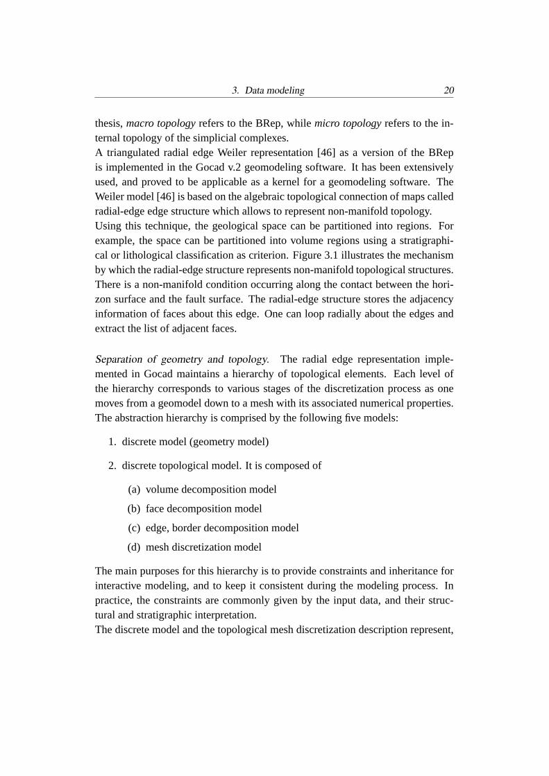
In his study of the combinatorial structure of cellular partitions Lienhardt [32]defined a combinatorial structure called generalized maps (GMap). This mathe-matical approach defines a class of representations named cellular models sinceeach kind of cell (vertice, edge, polygon, polyhedra, ...) plays an equivalent rolewithin the model. Cellular models may be thought of as a generalization of aBRep. Each element is recursively defined as a discretization of its border intoelements of lower dimension.The following definition is taken from Levy et al.[30]: ”The definition of G-Mapsis based on the incidence graph, which describes in a n-dimensional cellular modelall the possible paths that can be taken to go from a n-cell to a connected 0-cell,with arcs connecting only k-cells to (k-1)-cells, n>k>0 (figure 3.4). Consideringsuch a graph, it is possible to define relationships between two paths. For instance,in figure 3.4, two paths can be taken to go from face F1 to vertex V1, namely (F1;E1; V1) and (F1; E2; V1); as those two paths are identical but for the edges (1-cells), they are said to be 1-adjacent.
3. Data modeling 25
Fig. 3.4: Example 2-GMap (A) with its incidence graph (B)[30]
The properties of these relationships are mathematically well-defined and allow,together with the paths themselves, to describe completely the object. As a con-sequence, a n-dimensional object can be represented using a unique element typecalled dart, each dart standing for a path in its incidence graph. The adjacencyrelations between the paths are directly translated in terms of relations betweendarts. Thus, a k-adjacency between two paths is represented by a k-link betweenthe corresponding darts 1.” An example 2-G-Map is shown in figure 3.5.G-Maps allow to generically define polygonal curves, triangulated or polygonalsurfaces, tetrahedral or polyhedral volumes, or even arbitrary hypervolumes. Levy[31] proposed the cellular sub-partition of the geomodel space into ”macro-cells”representing volume geoobjects (figure 3.6). In this concept, a higher level GMapcalled ”frame” defines the explicit relations between objects of the same dimen-sion. The frame of a surface is composed of two oriented faces which are gluedby α2 involutions. A cellular volume model can be created by assembling adja-cent frames at a common border byα2 involutions. That way, a geomodel canbe created by a cellular partition where each 3-cell represents a volume region.Hierarchical GMaps allow to represent space subdivisions by connected orientedsurface which is in a way comparable to the radial edge data structure.The geometry and other properties can be represented separately with eachn-cell.This can be achieved by associating a discrete model with a GMap. A prototypeGMap software library has been implemented (”TopoLab” research project, [30])and proved to be applicable for geomodeling.

3. Data modeling 26
Fig. 3.5: Example 2-GMap with darts symbolized by bullet-headed segments,dotted lines stand for 0-functions, arcs of a circle correspond to 1-involutions,2-links are represented by double lines [30].
Fig. 3.6: A sub-partitioned GMap surface (left), and a GMap model build fromsub-partitioned surfaces (right) [30].
3. Data modeling 27
3.1.2.3 Object representations in cellular volumes
The object representations in cellular volumes can be considered a hybrid of objectrepresentation and field representation. Here a geoobject is modeled as a spatialregion which is filled with a regular or irregular tessellation composed of3-cells.Thus properties can be modeled in a discrete way within the whole geoobjectvolume. Two different approaches can be distinguished:
1. 3d tessellations with explicit topology.In Gocad, so calledSolid objectsare composed of connected tetrahedra resembling 3-simplicial complexes.That way a volume region which represents a geoobject and is bounded bytriangulated surfaces can be completely filled. The embedding and microtopology of the nodes is explicit defined in the data structure. Also, numer-ical properties are carried by vertices.Solid models can be associated with a BRep surface model in order toprovide such information. In Gocad, this approach is currently being imple-mented in so-calledSolidFrame models [29].Usinghierarchical GMaptopology the geomodel objects can be representedas macro cells which are decomposed by irregular 3-cells. That way, a full3d topological and property model can be created by a cellular volume par-tition.
2. Regular 3d grids with implicit topology.In Gocad,SGrids are curvilineargrids with parallelepipedic cells.SGrids can be deformed and cut in orderto fill the volume region of a geoobject defined by its boundary surfaces.Numerical properties can be carried by the cell nodes or the cell center. As adrawback, forSGrids no topological model comparable to BRep models orhierarchical GMaps exists. This makes it impossible to represent completegeological situations.SGrid models are being built only at a small scale,like for hydrocarbon reservoirs. Moreover, their creation is relatively time-consuming.
3.1.2.4 Polynomial geoobject representations
In the past years, Non-Uniform Rational B-Splines (NURBS) have evolved as anessential tool for a semi-analytical representation of geometrical entities encoun-tered in 3d CAD applications. However, splines and polynomial methods failto represent very irregular complex shapes which are required for geological ob-jects [9], and moreover polynomial functions of higher order are mathematically

3. Data modeling 28
very difficult to manipulate and have high computational demands. Therefore,such representations may only play a supporting role in geomodel building usingsparse data [26].
3.1.3 Regular 3d grid representation (Voxet)
A 3d grid defines a continuous space which is decomposed into 3-cells. The cellsare adjacent, connected, and addressable by an index. Parallelepipedic or curvi-linear grids are commonly used to represent properties in continuous 3d space.Properties can be assigned to the cells or grid nodes, and interpolated at any pointin the grid space. For example, a propertygeoobject.namecan be defined for agrid, which allows to represent identifiable geological units with a spatial extent.That way geoobjects can be represented as a set of cells filling the interior of thatgeoobject (figure 3.7). The spatial resolution depends on the cell size of the grid.The geoobject representation using grids is often limited to a particular kind ofdiscretization and connectivity.Field representations implemented using regular tessellations provide an implicitgeometry and topology which can be used for fast set theoretic spatial query com-putations.
Fig. 3.7: Field representation of 5 geoobject regions filling a Gocad Voxet. 2sections are shown. (data courtesy Mira Geoscience Ltd.)
3. Data modeling 29
3.2 Synthesis of a new spatial-geological data model for 3d GIS
3.2.1 Comparison of existing spatial geoobject representations
In the following section the different geoobject representations are discussed inrespect of their applicability for a 3d geoscience information system.Discrete object models feature a high flexibility to represent arbitrary shapes atarbitrary resolution, and allow the separation of the geometric embedding andcombinatorial macro- and micro topology. General drawbacks are the relativelyhigh roughness and high storage needs. However, in geomodeling a very preciserepresentation is hardly required. In Gocad both the roughness can be minimizedand input data be approximated in an appropriate way using the discrete smoothinterpolation method [34]. Such geomodels can represent the spatial extent ofnatural geoobjects. While for geological investigations, 3d mapping and visual-ization the modeling of volume geoobjects as surface-bounded regions or macrocells is sufficient, quantitative property modeling generally requires a volume dis-cretization into 3-cells.
Triangulated BRep. The triangulated radial edge boundary representation hasproved to be a stable and efficient data structure used for the Gocad geomodelingsoftware. Geological situations with very sophisticated geometry can be modeledwith consistent topology in a fast and user-friendly way. The radial-edge BRepmodels have the advantage that they encode the full topological structure of an ob-ject as well as the geometric information. The representation contains full topol-ogy information so that the relationships between vertices, edges, loops, faces andshells are available. The representation of macro- and micro topology in the tri-angulated BRep model allows for comprehensive query functionality. Drawbacksof the BRep approach are:
1. Eleven data types corresponding to the topological entities and numerousoperators are required
2. From a theoretical point of view, it has no concise algebraic foundation ascompared to GMaps. 3d geoobjects are represented as the interior volumeregion of their boundary surfaces and thus are rather ”emulated” instead ofrepresented directly.
3. No discrete 3d volume property modeling is possible. In practice the cel-lular partition corresponding to the BRep surface model is not appropriate

3. Data modeling 30
to comply with the needs of specific applications such as geostatistics. It isnecessary to partition these volume regions into smaller 3-cells in order tomodel spatial property variations inside a geoobject. To achieve this, BRepmodel regions representing geoobjects can be filled with grids (in Gocad:SGrids) or a tetrahedra tessellation (in Gocad:Solids). This method iscommonly used for property modeling in Gocad.
GMaps. GMaps allow to represent geological objects themselves as 3-cells in-stead of their 2-dimensional boundaries. Major advantages are the genericity andsimplicity to representn-dimensional objects using just one data type and opera-tor, and the possibility to represent the micro- and macro topology of geomodelsin one consistent data structure with an algebraic foundation. These facts providethe basis for a concise implementation of GMaps as a geomodeling software ker-nel. A prototype GMap-based implementation has been developed by the Gocadresearch consortium, which is however not mature to be used as component for a3d GIS.With respect to 3d topological query functionality, hierarchical GMap models canprovide an elegant way to implement a query language based on the concept ofinvolution. Similarly to the BRep, a comprehensive set of queries based on themicro- and macro topological model can be compiled.
Volume representation. In the tessellated volume object representation spatialqueries have to be computed using the geometric and explicit topological prop-erties. Such models are useful for fast queries on discrete properties. Regularcurvilinear grids or volume tessellations which are constrained by a boundaryrepresentation are widely used in practice for discrete property modeling of singlegeoobjects like hydrocarbon reservoirs or ore bodies.The disadvantage of the grid approach is that the explicit macro topological BRepmodel exists independent from the grid objects, which fill BRep model regionsrepresenting geoobjects. On the other hand, the use of curvilinear grids makes itpossible to model numerical properties of a geoobject in a fast and discrete way.Tetrahedra-tessellated solids integrated with a BRep surface model, like theSolidFrame approach [29], can provide a means to maintain both the spatialextent of geoobjects and their discrete properties in one model.A promising solution to represent topology, geometry, and properties in a unifiedway is the development of hierarchical GMap models [31] whose macro cells aredecomposed into discrete 3-cells. GMap based volume models are very qualified
3. Data modeling 31
for a 3d GIS, as the combination of the topological features of GMaps withdiscrete volume property modeling leads to a unified geomodel on which a richset of spatial and property queries can act.However, in practice such full geomodels are often not accessible because suffi-cient property data is available only in a very limited region, like a targeted orebody or hydrocarbon reservoir, and not throughout the whole geomodel space.This can lead to a mixed representation, where some well-sampled target regionsare decomposed using 3-cells for property modeling, and other regions are justrepresented by their dividing walls.
3d grid regular representation. The grid representation allows fast property com-putations and topological queries. As the topology between the regular 3-cellsis implicitly given, queries for neighbourhoods are straightforward. On the otherhand, no macro topological model is defined and queries on the topological neigh-bourhoods and connectivity of geoobjects have to be computed from the elemen-tary topology of the cells. Another drawback is that the spatial resolution is limitedby the cell size, which results in very large storage costs for good approximationsof distict features like faults.
3.2.2 The feasible solution: a Gocad- and GML-conform spatial geologicaldata model
A geoscience information system framework should be based on a comprehen-sive data model for geological observational data and geomodels following therequirements given in chapter 2. These include primarily:
1. representation of all 3d geomodels and observational data which are relatedto one geological situation (see figure 2.1) in one project. Data includeparticularly the 3d geometry, topology, and textual and numerical geologicalproperties.
2. conformable with the GML [22] specification for geospatial data exchangeusing XML format
3. compatible with 3d geomodeling software
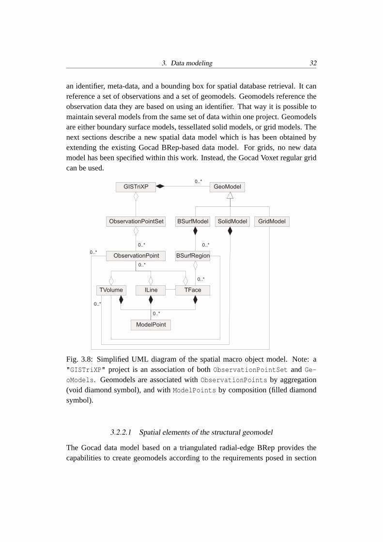
In order to fulfil these criteria, a new data model has been synthesized by addingthe concept of observation points to the BRep-based data model of Gocad. Thedesign of the data model is depicted in figure 3.8. A project essentially contains
3. Data modeling 32
an identifier, meta-data, and a bounding box for spatial database retrieval. It canreference a set of observations and a set of geomodels. Geomodels reference theobservation data they are based on using an identifier. That way it is possible tomaintain several models from the same set of data within one project. Geomodelsare either boundary surface models, tessellated solid models, or grid models. Thenext sections describe a new spatial data model which is has been obtained byextending the existing Gocad BRep-based data model. For grids, no new datamodel has been specified within this work. Instead, the Gocad Voxet regular gridcan be used.
0..*
0..*
0..*
0..*
0..*
0..*
0..*
0..*
GISTriXP
ObservationPoint
BSurfModel
GeoModel
TFaceILine
ModelPoint
TVolume
BSurfRegion
SolidModel GridModelObservationPointSet
Fig. 3.8: Simplified UML diagram of the spatial macro object model. Note: a"GISTriXP" project is an association of bothObservationPointSet andGe-oModels. Geomodels are associated withObservationPoints by aggregation(void diamond symbol), and withModelPoints by composition (filled diamondsymbol).
3.2.2.1 Spatial elements of the structural geomodel
The Gocad data model based on a triangulated radial-edge BRep provides thecapabilities to create geomodels according to the requirements posed in section
3. Data modeling 33
2. Although the BRep model is in some respects inferior to hierarchical GMapmodels, the data models are comparable and convertible [14]. Thus a similar setof micro- and macro topological and geometrical queries is possible. Because ofGocad’s common usage and sophisticated geomodeling functionality this thesisaims to design and implement a GIS which will integrate with the released Gocadversion and be compatible with its data model. The resulting spatial data modelused here has the following substantial characteristics:
• topology and discretization. Geomodels are decomposed by a hierarchicalexplicit topological model (triangulated radial edge ”Weiler” BRep, [46]).Depending on their dimensionality, geoobjects can be represented as sur-faces or surface-bounded volume regions. This approach is implemented inthe Gocad geomodeling software.
• differentiation betweenModelPoints andObservationPoints. Model-
Point vertices are members of the geoobjects and represent points whichare introduced during the geomodeling process in order to achieve modelswith smoothly interpolated geometry and numerical properties.Observa-
tionPoints contain the actual input data.
• object orientation. Geoobjects encapsulate both a spatial and a geologicproperty description. The topological geoobject data model is compatiblewith the data model of the Gocad geomodeling software:
1. Lines are used to represent a set of polylines, whoseModelPoints
andObservationPoints are connected by segments. ALine is a setof topologically isolatedILines.
2. Surfaces is a set of topologically closed triangulated surfaces calledTFaces. In the spatial data model, surfaces are used to represent 3dgeological boundaries like fault surfaces, stratigraphic boundaries, orother discontinuities.
3. BSurfModel (corresponding toModel3d in Gocad) is used to sub-divide the geomodel space into topological closed volume regionsbounded by a set of orientedTFaces. BSurfModel is an implemen-tation of the triangulated radial edge BRep model [46]. In addition,BSurfModel provides the possibility to group regions to layers orfault blocks. For example, a region can belong to both a fault blockand a stratigraphic horizon. The BRep model macro elements cancarry properties including geological semantic.

3. Data modeling 34
4. TSolids represent a set ofTVolumes. TVolumes are tetrahedric 3-cellcomplexes which can be used to fill the volume regions ofBSurf-
Model objects.
The root element is a projectGISTriXP (The name was chosen to reflect”GIS”, ”Tri” for 3d, ”X” for XML, and ”P” for project). The children Ob-
servationPointSet andGeoModel contain observed and modeled data, respec-tively. GeoModels can be subdivided into irregular tessellated surface models(BSurfModel), solid models (SolidModel), and regularGridModels as shown infigure 3.8. The irregular tessellated models may contain also isolated collectionsof isolated objects:PointSets, PLines, andTSurfs. These collections are notdepicted in figure 3.8.The Gocad objects have been extended by a new object namedMetaGeoObject,which is an aggregation of faces or regions. This allows to group topological el-ements which conceptually belong together, like for example a set of conjugatefaults, or a set of layers which belong to one stratigraphic group.The child nodeObservationPointSet represents the set of input data points.These are referenced by the model objects by an ID and can be shared by mul-tiple geomodels. TheObservationPoints can act as constraints for the modelbuilding process. AnObservationPoint contains all data collected from one ge-ological observation point.BSurfModels andSolidModels contain pointers toObservationPoints. That way it is always possible to distinguish and query theobserved data points which a model is based on.Besides theObservationPoint references, theBSurfModels andSolidModelscontain a set ofModelPoints which represent supporting nodes. These are gen-erated by applications to build smooth triangulations with a good approximationof input data. Opposite to theObservationPoint, they are not referenced but amember of the models.
Interoperability. For many geoscientific projects in research and resource explo-ration it is essential that different software components like databases, geomodel-ers, and GIS can exchange their data without losses. This can be achieved by theuse of ISO-standards conform data models.The data model presented in section 3.2.2.1 is largely equivalent to the Gocaddata model, and the object classes representing cell complexes have correspond-ing elements in the X3D [47] specification and the GML 3.0 ([22]) specification(see table 3.1). This allows the conversion between these formats and maintaining

3. Data modeling 35
the geoobject topology and geometry. For example, the triangulated surface classTFace in Gocad corresponds to the GML elementFace and the X3D elementIn-dexedFaceSet. A major advantage of the Gocad spatial data model compared tothe GML, X3D and GeoToolKit [4] data models is the macro topological model.The extended data model has been created in UML notation [44]. The UMLmodels were transferred to valid XML Schemas for 3d geomodels and geologicalobservation data. Derived by extension from GML and therefore compatible arethe following XML elements: abstractObject type, simple types including IDand IDREF, geometry types includingSolid, triangulatedSurface, Curve, Mul-tiPoint, AbstractTopology, meta-data types, and simple property types. Themajor differences are the representation of sets of 3d geomodels with 3d topol-ogy instead of unique geographic features, and the distinction of contained modelpoints and referenced observation points.
Gocad v.2 GML v.3 X3D v.1
0d - point Atom Node PointSet1d - line ILine Edge IndexedLineSet2d - surface TFace Face IndexedFaceSet3d - volume TSolid - -3d - macro volume Model3d - -
Tab. 3.1: Table of equivalent classes of topological model objects of the Gocad, X3D, andGML data model.
Non-spatial elements of the data model. In order to develop geological queryfunctionality, geoobjects comprise besides spatial data also non-spatial propertieswhich can be defined for the entire geoobject using functions. These primarily in-clude the geoobject definition criteria and describe the semantic of the geoobjectrepresented by BRep-model elements. For example, a geoobject representing astratigraphic bed can have constant propertiesAge, Genesis, Lithology; a faultmay have constant propertiesType, Orientation of slip and fault plane, andTimeInterval of activity. Also spatially non-constant functional properties canbe defined for geoobjects. For example, for a model volume region a propertystressScan be defined and a functionS→ f(depth) can be assigned to it. Thus, astress value exists for every point in the model volume region.

3. Data modeling 36
Properties can also be defined in a discrete way. In the Gocad geomodeling soft-ware, the vertices of tessellated geoobjects contain a vector with numerical prop-erties including the location vector. For each property, a set of constraints can bedefined. In the data model provided here, these vertices correspond toModel-
Points andObservationPoints in figure 3.8. WhileModelPoints can carryinterpolated numerical scalar and vectorial values, the referencedObservation-
Points may possess comprehensive geological information.
3.2.2.2 ObservationPoint data model
GeoRelationship
+
+
+
+
From
To
Parent
Child
:
:
:
:
Lithology
+
+
+
+
+
Fabric
Texture
Composition
RockName
Color
:
:
:
:
:
GeoProcess
+ Type :
PropertyDescription
Event
+ Age :
Age
Genesis
GeoObjectPart
ChronoStratUnit
TectonicUnit
BioStratUnit
LithodemicUnit
TimePoint
TimeInterval
StructuralRel
TemporalRel
IntrusiveRel
StratigraphicRel
SpatialRel
RockClassificationTimeScale
PhysicalProperty
ImageDescription
Structure
+
+
Type
Measure
:
:
TextDescription
ObservationPoint
+
+
ID
Geometry
:
:
GeoObject
+ ID :
MetaData
+
+
Autor
Date
:
:
DataQuality
+
+
Certainty
Completeness
NamedInterval
Petrology
+ MetamGrade
Fossil
ChemicalDesc
Fig. 3.9: Simplified UML representation of the ObservationPoint data model. Thetop-level elements are shown in blue. Only top-level associations and attributesare depicted.
3. Data modeling 37
The heterogeneous, semi-structured descriptive and quantitative observationaldata associated with one sampling location are stored asObservationPoint ob-ject. Drillhole samples can be modeled as sets ofObservationPoints locatedalong a line.For this work, the NADM 43a [40] conceptual geological data model is adaptedas the basis for the observation data model. The NADM 43a is the currently mostcomplete, standardized conceptual data model for geological data. The concep-tual data model has been transferred to a logical data model in UML and XMLSchema language. Figure 3.9 shows an UML representation of theObservation-
Point data model. All properties of complex data types are encapsulated in objectclasses. AnObservationPoint has a geometry attribute and is associated withthe following classes:
1. Properties cover any type of description and measurements related to theobservation point.ImageDescription, TextDescription, andMetaData allow to describegeneral properties of an outcrop like weathering, situation, and metadataincluding author and sampling date. TheAge property includes age deter-mination method and error. Two specializations ofAge exist: TimePointandTimeInterval. TimeInterval which can be of typeNamedInterval.Lithology describes the material properties of a sample and is in associa-tion with other properties includingAge, PhysicalProperty, Structure,Petrology, MetamorphicGrade, andFossil.Structures may be of type contact, fracture, fault, fold, bedding, lineation,foliation, and may have an orientation vector property.Structures can beassociated with stress and strain physical properties, and may be aggregatedin aCompoundStructure.
2. GeoProcesses include descriptions of diagenesis, alteration, intrusion, vol-canism, deformation, crystallization, deposition, erosion, and metasoma-tism. Events are temporally limited occurrences ofGeoProcesses. Thesummary ofEvents describes theGenesis of an ObservationPoint orGeoObject.
3. For anObservationPoint, theGeoObject class describes its membershipof an identifiable volumetric part named ”unit” of the Earth based on prop-erties. Commonly composition, geological age, structures and tectonics, orphysical properties are used to define geoobjects.

3. Data modeling 38
4. Relationships between geoobjects. A geoobject can have a role propertywhich defines its relationships relative to neighbour geoobjects, for exam-ple ”this geoobject was thrust over geoobject B, C”, ”this geoobject offormationα is stratigraphically included in geoobject B of groupβ” . Bi-nary relationships can be generically described by a ”From-To” property ora ”Parent-Child” property. That way also topological relationships can bestored together with their geological semantics.
TheObservationPoint UML model has been converted to valid XML Schemadocuments. The elements can be extended, restricted or substituted to fulfill therequirements of special user groups and tasks. The provided model can almostbe seen as a metamodel because several parts can be customized for differentpurposes.

4. SPATIAL AND NON-SPATIAL QUERIES ON GEOOBJECTS
An essential functionality of GIS is the capability to select and investigate geodataby the means of query. While the aspects of relational database queries, 2d spatialand geological queries have been extensively studied in the context of 2d GIS (see,for example, [7], [33]), very few workers consider 3d spatial queries, namely M.Breunig [9]. In addition to examining spatial queries in a topological 3d model,this chapter will emphasize queries which are of particular interest to geologyincluding 3d directional queries, and queries with combined geological and spatialparameters. According to the query parameters, query functions on geoobjects canbe grouped into four classes:
• topological queries
• geometrical queries, including buffer queries and direction-based queries
• queries based on geological properties of geoobjects, including semanticalqueries
• queries based on discrete numerical properties
In the following sections a theory for spatial geological query functionality is de-veloped. In order to prove the concepts, an implementation has been realized asplug-in software library for Gocad and as a query language for XML data man-agement.
4.1 Classification and formalization of spatial query functions
In order to develop generic spatial GIS functions, a query language containingall elements to formulate a spatial query in euclidean spaceR3 as mathematicalset-theoretic expression is required. For this work the concept of generic databasequeries [37] has been adopted to examine spatial queries on discrete 3d geomodelobjects. The example figure 4.1 represents a set of geological observation pointsP with propertyrocktypegranite, limestone and one spatial geoobject regionR

4. Spatial and non-spatial queries on geoobjects 40
⊂ R3. The following queries illustrate the different groups of spatial propertiesthat can be distinguished by a query:
Fig. 4.1: Querying the spatial relationships of observation points. A granite bodyis symbolized in grey, the surrounding region is limestone. The query results areshown in color: granite observation points are red, limestone points are green.
1. Select the set of pointsQ1(P) ⊂ P with rock type”granite” . This queryis independent of the spatial location of the points. This type of query isa pure set-theoretic, non-spatial database query, and formal languages likeSQL (for relational databases) and XQuery (for XML databases) exist toexpress them.
2. Select the set of pointsQ2(P)⊂ P in the topological interior R. This queryis independent of any homeomorphism and it is thustopology-invariant.Such queries can only be answered using a standard DBMS if topologicalrelationships are explicitly defined in the data model. This would be thecase with queries on spatial regions or faces in a BRep or GMap Model.
3. Select the set of pointsQ3(P) = p0, ..., pn|n> 1 ⊂ P that are on a straightline. This group ofsimilarity-invariant queries preserves the angles and
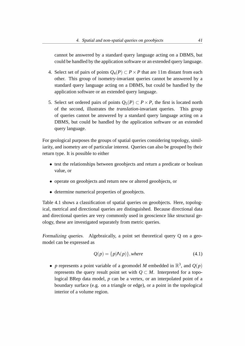
4. Spatial and non-spatial queries on geoobjects 41
cannot be answered by a standard query language acting on a DBMS, butcould be handled by the application software or an extended query language.
4. Select set of pairs of pointsQ4(P) ⊂ P×P that are 11m distant from eachother. This group of isometry-invariant queries cannot be answered by astandard query language acting on a DBMS, but could be handled by theapplication software or an extended query language.
5. Select set ordered pairs of pointsQ5(P) ⊂ P×P, the first is located northof the second, illustrates thetranslation-invariant queries. This groupof queries cannot be answered by a standard query language acting on aDBMS, but could be handled by the application software or an extendedquery language.
For geological purposes the groups of spatial queries considering topology, simil-iarity, and isometry are of particular interest. Queries can also be grouped by theirreturn type. It is possible to either
• test the relationships between geoobjects and return a predicate or booleanvalue, or
• operate on geoobjects and return new or altered geoobjects, or
• determine numerical properties of geoobjects.
Table 4.1 shows a classification of spatial queries on geoobjects. Here, topolog-ical, metrical and directional queries are distinguished. Because directional dataand directional queries are very commonly used in geoscience like structural ge-ology, these are investigated separately from metric queries.
Formalizing queries. Algebraically, a point set theoretical query Q on a geo-model can be expressed as
Q(p) = p|Λ(p),where (4.1)
• p represents a point variable of a geomodelM embedded inR3, andQ(p)represents the query result point set withQ⊂ M. Interpreted for a topo-logical BRep data model,p can be a vertex, or an interpolated point of aboundary surface (e.g. on a triangle or edge), or a point in the topologicalinterior of a volume region.

4. Spatial and non-spatial queries on geoobjects 42
Topologicalqueries
Metrical queries Directionalqueries
Relationshipsreturning booleanvalues or geoob-jects
disjoint, equal,intersect, covers,covered, inside,neighbourhood(disjoint withcommon border),connected (byother objects)
in spatial buffer in directionbuffer, relativesituation
Operatorsreturn-ing new or alteredgeoobjects
union, difference,intersection,complement
translate, re-interpolate, addcell, delete cell,...
rotate
Propertiesreturn-ing real values
number of inter-sections, numberof neighbours,number of bor-ders, genus,
unary: length,surface, volume,curvature;binary:distance, dis-placement
binary: angle
Tab. 4.1: Table showing a classification of spatial queries on geoobjects.
• Λ(p) represents a combination of terms with quantifiers onp (∃ and∀),functions, boolean operators (∧, ∨ and¬), and predicates.
• a term contains a relation (<,≤,=,≥,>,6=), or functions.
For example,”Select the set of pointsP within a buffer of 10m of the faultsurfaceF” can be written as:
Q(p) = p|∃ f ∈ F ∧d(p, f ) < 10m
A geomodelM can define a point set topology on the subsurface space, and ageoobject corresponds to the closureRof a point setR⊂M. For answering querieswhich are focused on geoobjects instead of abstract point sets, equation 4.1 canbe written asQ(R) = R|Λ(R).
”Select the geoobjectsR of a geomodel M with a volume v>100m3” can nowbe be formulated as:
Q(R) = R|v(R) > 100m3

4. Spatial and non-spatial queries on geoobjects 43
It is possible to combine multiple spatial and also non-spatial query termslogically using set theoretic operators:”Select the geoobjectsR which are at leastpartly within a buffer of 30m of fault surface S AND have a volume v>100m3”can be formulated as:
Q(R) = R|v(R) > 100m3∧∃a∈ R∧∃ f ∈ F ∧d(a, f ) < 30m (4.2)
4.2 Topological queries
4.2.1 Theory of topological queries
Combinatorial topological structures such as BRep-models and GMaps are beingused to build discrete topological geomodels. The set of geoobjects comprisinga geomodel can be abstracted as topological point sets and examined usingpointset theoretic queries. Topological queries are set operations based on topologi-cal relations of these sets such as intersection, difference, union, and topologicalproperties such as connectivity and homeomorphism. Three types of topologicalqueries can be distinguished:
• Object queries: ”Which geoobjects have a certain relationship with a givenobject?”
• Relationship queries: ”Which topological relation exists between givengeoobjects?”
• Topological property queries: ”Select all geoobjects with given topologicalproperties.”
Topological queries on a set of geoobjects can be solved by examining the topo-logical relationships of the set of binary combinations of geoobjects. As shown byEgenhofer and Franzosa [16], point set topological relations based on the notionsof interior R and boundaryδR can be equated with general set operators. Binarypoint set topological relationships can be classified by the 3x3 intersection matrixdeveloped by Egenhofer [16, 17]. This formal and complete model is based onthe overlapping properties of the interior (R1,R
2), the complement (R−1 , R−2 ), and
the boundary (δR1,δR2) of two topological regionsR1,R2.
Rel(R1,R2) =
δR1∩δR2 δR1∩R2 δR1∩R−2R1∩δR2 R1∩R2 R1∩R−2R−1 ∩δR2 R−1 ∩R2 R−1 ∩R−2
(4.3)
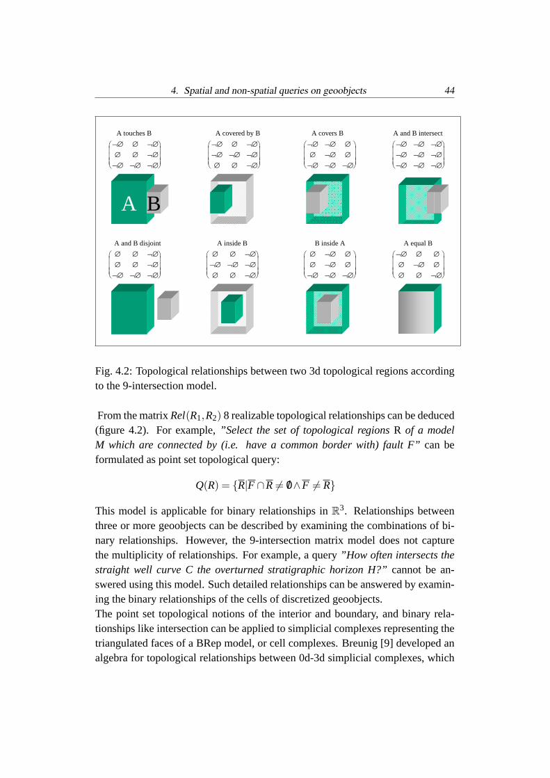
4. Spatial and non-spatial queries on geoobjects 44
A touches B A covered by B A covers B A and B intersect
A B
A and B disjoint A inside B B inside A A equal B
¬∅¬∅¬∅¬∅∅∅¬∅∅∅
¬∅∅∅¬∅¬∅¬∅¬∅∅∅
¬∅¬∅¬∅∅¬∅∅∅¬∅∅
¬∅∅∅∅¬∅∅∅∅¬∅
¬∅¬∅¬∅¬∅∅∅¬∅∅¬∅
¬∅∅∅¬∅¬∅¬∅¬∅∅¬∅
¬∅¬∅¬∅∅¬∅∅∅¬∅¬∅
¬∅¬∅¬∅¬∅¬∅¬∅¬∅¬∅¬∅
Fig. 4.2: Topological relationships between two 3d topological regions accordingto the 9-intersection model.
From the matrixRel(R1,R2) 8 realizable topological relationships can be deduced(figure 4.2). For example,”Select the set of topological regionsR of a modelM which are connected by (i.e. have a common border with) fault F”can beformulated as point set topological query:
Q(R) = R|F ∩R 6= /0∧F 6= R
This model is applicable for binary relationships inR3. Relationships betweenthree or more geoobjects can be described by examining the combinations of bi-nary relationships. However, the 9-intersection matrix model does not capturethe multiplicity of relationships. For example, a query”How often intersects thestraight well curve C the overturned stratigraphic horizon H?”cannot be an-swered using this model. Such detailed relationships can be answered by examin-ing the binary relationships of the cells of discretized geoobjects.The point set topological notions of the interior and boundary, and binary rela-tionships like intersection can be applied to simplicial complexes representing thetriangulated faces of a BRep model, or cell complexes. Breunig [9] developed analgebra for topological relationships between 0d-3d simplicial complexes, which

4. Spatial and non-spatial queries on geoobjects 45
can be generalized for cell complexes. LetR1 andR2 be two discrete geoobjectsrepresenting two topological regions, it is possible to define the set of possiblebinary topological relationships if the following sufficient conditions are true:
1. If all cells ofR1 aredisjoint with all cells ofR2 ⇒ R1∩R2 = /0
2. If all cells ofR1 andR2 are by pairsequal⇒ R1≡ R2
3. If a boundary cell ofR1 touchesa boundary cell ofR2 from the outside andif all other cells ofR1 are disjoint to all other cells ofR2 (neighbourhood)R1∩R2 6= /0
4. If a cell ofR1 intersectsa cell ofR2 ⇒ R1∩R2 6= /0
5. If a boundary cell ofR2 touchesa boundary cell ofR1 from the inside andif all other cells ofR2 are insideR1 (R1 coversR2) ⇒ R1⊃ R2
6. If a boundary cell ofR2 touchesa boundary cell ofR1 from the outside andif all other cells ofR1 are insideR2 (R1 covered byR2) ⇒ R1⊂ R2
7. If all cells ofR1 areinside the boundary cells ofR2 ⇒ R1 ∈ R2
8. If all cells ofR1 areoutsidethe boundary cells ofR2 ⇒ R2 ∈ R1
Since this can give different answers for the simplices of an object (e.g. someoverlap and some are contained) a superior topological relationships has to bedetermined: overlap> covers, covered-By, meet> contain, inside [9].The return value of a topological query can be either a selected set of geoobjectsor the type of the topological relationship of a given set of geoobjects. The resultset of a relationship query can be deduced from an object query, for example thequery”Is region R1 a neighbour of region R2?” is true if R1 is contained in theresult set of query”Select the neighbour regions of R2” .Topological propertiesare spatial properties which are invariant under topologicaltransformations, like the genus. The genus can informally be regarded as thenumber of holes in a surface. The related Euler-Poincare characteristic allows tocheck the topological validity of a model with manifold topology. It states that
V−E +FL− IFL = 2(S−G),
where V... number of vertices, E... number of edges, FL... number of face loops,IFL... number of inner face loops, S... number of shells, G... Genus. However,

4. Spatial and non-spatial queries on geoobjects 46
this formula is not valid in non-two manifold topologies encountered in a radialedge BRep. Besides the invariants, the combinatorial topological properties likenumber of boundary loops or faces of a volume region may be used to characterizegeomodels.
4.2.2 A concept of topological queries in 3d
4.2.2.1 Queries based on the tessellation
In general, queries on the tessellation of a geomodel, also named ”micro topol-ogy”, are not directly required for geological purposes. However, as stated in thelast section, topological queries concerning the implicit topological relationshipsbetween geoobjects can be answered using the tessellation and the geometry. Forexample, in order to investigate the relationships between a set of surfacesS, theintersection of the surfaces has to be computed. This can be achieved by testingfor each combination of the surfaces their sets of triangles for intersection. Thisgives a boolean result for each pair of surfaces.In order to avoid unnecessary computations, the intersection is computed in threesteps. First the oriented minimum bounding boxes of the surfaces are tested forintersection using the method of separating axes [23, 15]. If the bounding boxesintersect, the search can be refined by computing the octrees of the tessellated sur-faces (depicted in figure 4.3) and finally testing the intersection of closely locatedtriangles. The Gocad software provides an implementation of an octree-enhancedintersection test.For queries whose return value are altered spatial objects, the intersection linesand the re-triangulation of the tessellation have to be computed. Examples forsuch queries are the join, difference or intersection of a set of triangulated sur-faces or volumes. The problem of surface and volume cutting and re-triangulationhas been studied by previous workers (for example Euler [19]). This functionalityis available in the Gocad software.
4.2.2.2 Queries using explicit macro topology
If a geomodel maintains explicit adjacency relationships between topological en-tities, then queries on the topology can be performed using the combinatorialdatabase without geometrical computations. The query algorithms have a com-plexity O(n) which is linear proportional to the number of topological elementsinvolved. Thus, even with very large models rapid query responses are possible.

4. Spatial and non-spatial queries on geoobjects 47
Fig. 4.3: A Gocad BRep model where two fault surfaces are intersecting, twoare disjoint, two are touching, and all three are touching the terrain surface. Therelationship computation between the triangles is accelerated by the octrees.
Explicit adjacency relationships can be defined for all topological elements us-ing topological spatial data models like BRep or GMap. According to the queryuse cases (section 2.4), queries on topological geoobject relationships are of par-ticularly high interest in a GIS. These are aimed at sub-selecting, checking, andanalysing the set of geoobjects which constitute the geomodel.
BRep model. Queries on topological relationships can efficiently be answeredusing a topologically manifold triangulated radial edge BRep geomodel. Both theincidence and adjacency relationships of the topological elements can be used toanswer queries for connectivity, decomposition, neighbourhood, and orientation.In theory, thirty six element adjacency relationships are possible in a non-twomanifold BRep with respect to six basic topological elements (vertex, edge, loop,face, shell and region). For geological query purposes, only the relationshipsbetween macro elements with a geological meaning, like region, shell and face,are required. Based on the following three BRep-model topological elements,query functionality has been developed in this thesis and implemented in a Gocadplug-in:
• Loops (also named BFrameElements in Gocad) in a BRep model usuallyrepresent the touching line of three or more face-bounded volume geoob-

4. Spatial and non-spatial queries on geoobjects 48
jects called regions. Loops are associated by pointers with topologicallymeeting faces. This allows to answer queries for the faces meeting at a loopefficiently by iterating through the pointer list.Topological properties of loops may also be of interest. For example, if aregion is bound by one face withG closed loops, it can be deduced thatGtouching relationships with at mostG neighbouring regions occur. Here,Gcorresponds to the genus of the face.
• The set of faceuses can be queried for their loops, mates, and closedness.Faces without loops constitute closed volumes with one neighbour region.The neighbour regions can be determined from faceuse mates.
• The set of regions can be queried for their boundary faces.
A connectivityquery like ”Are two faults A, B connected by other faults?”caneasily be answered in a BRep model provided by the Gocad data model, becauseincidence and adjacency information is stored in double-linked lists which can besearched by iteration. A query function for connectivity which takes two regionsor faces as argument and returns a boolean value has been implemented in thiswork.In a BRep model, the incidence and adjacency relationships between the topolog-ical elements are representable by a hierarchical graph. This could be used forvisualization and inspection of the topology of a model.
4.2.2.3 Queries using implicit macro topology
Point set-theoretic spatial queries are applicable for explicit or implicit topologi-cal relationships. Implicit topological relationships are defined by the geometricalmodel but not by the topological model. Thus, they have to be computed from thegeometrical model to answer queries. For example, if two surface objects inter-sect each other, computational geometry algorithms can determine the intersectionand thus the topological relationship between these surfaces. Such queries have ahigher computational complexity than queries using geomodels with a topologicaldatabase. In cases where the geometrical model has gaps or other errors which areinconsistent with the explicit topological model, the comparison of the topologycomputed from the geometry and the explicit topology can provide a means todetect such errors.General point set topological queries can be translated to combinatorial topologyqueries acting on discrete geomodel objects as shown in table 4.2.

4. Spatial and non-spatial queries on geoobjects 49
A method to detect topological relationships from the geometry are intersectiontests for a set of topological elements. These can be of a different geometricaldimension. For example, the number of intersection points of a line and a sur-face can be determined. In general, the result can be either a selected set ofintersecting/non-intersecting objects, or a boolean answer if the given surfacesintersect each other, or how many intersections occur. The answers generated byintersection tests provide the basis for further investigations on topological prop-erties of multiple objects, like connectivity.
point set topological elementWeiler model elementboundary shell (in Gocad: BFrame)interior regionclosure region + shell
Tab. 4.2: Translation between point set topological elements and Weiler model elements.
Intersection and union. The first step of a topological query between geoobjectsis to compute their intersection. Starting from the intersection test, it is also pos-sible to compute the difference and union of geoobjects.Geoobjects to be tested for intersection can be both simplicial complexes like tri-angulated surfaces without macro topology, and a set of geomodels with internalmacro topology. For example, such a request can be”Compute the intersection ofregion A, B, where A, B belong to different geomodels.”. For large sets of geoob-jects it is worthwhile to compute the intersection of bounding boxes first. Thefollowing algorithm iterates through adjacent topological elements in their inci-dence order. When the bounding boxes of two faces overlap, the intersection canbe computed from the intersection of the triangles of the faces:
if bounding boxes of region A, B overlap
for each face in region A
if bounding box of face A overlaps bound box of region B
for each face in region B
if bounding boxes of face A and face B overlap
compute intersection of face A, face B
For different geomodels, the spatial operators have to respect and maintain thegeological semantics of the geoobjects. This will be shown by the following ex-ample. The union of different geomodels is of interest if within an area several

4. Spatial and non-spatial queries on geoobjects 50
models exist. Geological surveys often create models with low resolution at re-gional 3d mapping scale, and versioned detailed models at a local, project orientedscale. Their intention is to unify these models in order to show the regional ge-ological setting of the detailed models. For this purpose, the geoobjects to beunified have to represent the same geological semantic, like parts of an identicalfault or horizon. The following method to unify geomodels has been implementedin a Gocad wizard:
1. input: two at least partly intersecting BRep geomodels: regional modelRand detailed modelD with bounding boxes
2. cutting the modelRwith modelD
3. deleting all objects which belong toR and are located within the boundingboxD
4. binary relationships between semantically identical geoobjects of modelsRandD are created. The geoobjects are merged by adding the parts derivedfrom modelD to the parts derived from modelR. Alternatively, a new uniongeoobject may be created.
5. post-processing and re-interpolation is required in order to remove gaps be-tween the two models. This can be done by creating surface patches orconstraining unwanted internal borders at the former bounding box cuttingsurface, and re-interpolating the surfaces.
This results in a smooth union of surfaces from two models. However, only identi-cal geoobjects can be merged. If both models are generalized to the same level andcontain the same set of geoobjects, this will result in a consistent model. Other-wise, if for example the detailed model is less generalized and thus contains moregeological boundaries, these abundant surfaces are not contained in the resultingtopological BRep model.
4.2.2.4 Topological queries using volume models
Implicit topology - grids. In 2d GIS, operations on 2d spatial neighbourhoodscalled filters are commonly used to, for example, smooth data, enhance edges ordirectional features such as lineaments, characterize textures, or derive shape in-formation such as slope [7]. Spatial filter techniques can also be used in 3d grids.Regular parallelepipedic 3d grids like the GocadVoxet objects have an implicitly

4. Spatial and non-spatial queries on geoobjects 51
defined neighbourhood relationship between the sets of cells. All grid nodes ex-cept nodes at the boundary have six neighbour grid nodes. Likewise, a cell sharesits boundary with six neighbours. This relationship is being used by many imageprocessing tools. For example, 3d seismic image processing algorithms can detectpatterns based on the neighbourhood relationship of cells with similar impedance[27, 3]. Due to the many specific usages and the limited time-frame of this thesis,3d image processing tools have not been examined.
Explicit topology - tessellations. Volume tessellation geomodels like the GocadSolidModel can contain an explicit macro-topology represented by the recentlydevelopedSolidFrame, and micro-topology comprised by the tetrahedric tessel-lation. TheSolidFrame is a radial edge BRep-model created from a 2d-cellularpartition of the boundaries of 3d volume regions. That implies that it is easy tonavigate through the topological elements and pose topological queries. Possiblequery functionality is thus similar to the BRep-model examined in section 4.2.2.2.In addition, the tetrahedric volumes filling theSolidFrame regions possess an ex-plicit topology between their nodes. However, for geological queries these arenot useful as the relationships between tessellation nodes which do not representgeological objects has no geological meaning.
4.3 Geometrical queries
Geometrical queries are the most used in 2d GIS, and similar functionality canbe made available in a 3d GIS. The geometry of any point of a geoobject canbe defined by a location vector triplet [x,y,z] in a Euclidean coordinate system.Based on their geometrical properties, either subsets of geoobjects (buffer queriesand relative location queries) or real numbers (property queries) can be obtainedas result of queries. Geometrical geoobject queries can be classified as follows:
1. Distance buffer queries, for example:”Select all geoobjects which are situ-ated within a certain distance of a given geoobject.”, or:”Select all points of a geoobject which are within a given distance of a givengeoobject.”
2. Property queries. These return a geometrical property like length of a bor-der, highest point of a surface, area of a surface, volume of a closed surfaceor model volume region, or curvature.

4. Spatial and non-spatial queries on geoobjects 52
3. Orientation queries can, for example, select the set of faults with a givenorientation.
4. Relative location queries, for example:”Select all geoobjects above, below,between, north, east, south, or west of given geoobjects.”
4.3.1 Distance buffer queries
Given a geometrical objectO and a constant distanced as parameter, the set ofgeoobjects or the points of geoobjects which are within a given distance bufferbcan be determined by computing the distance between the vertices of the objects.This buffer is equivalent to the sum of point buffers of the vertices ofO. Threedifferent cases of Euclidean distance buffer queries have been implemented inGocad within this work:
1. ”Select the geoobjects which are completely within the buffer.”Here, allvertices of the queried geoobject have to fall within the buffer.
2. ”Select the geoobjects which are at least partly within the buffer.”returnsall geoobjects, where at least one of the vertices is within the buffer.
3. ”Select all the points of a geoobject which are within the buffer.”computesa list of vertices which are within the buffer. This query can either return thelist of vertices as points set, or visually highlight the parts of the geoobjectwhich are within the buffer as shown in figure 4.4. This is realized by com-puting a boolean value telling whether a vertex is within the buffer. Thisvalue is used for interpolating the color opacity valueα for each triangle.
4.3.2 Geometrical property queries
For the characterization of geological structures often geometrical properties areused. From a 3d geometrical geomodel, the following important properties can beobtained:
• from one geoobject (unary):length, surface, volume, curvature of onegeoobject. These functions are available in Gocad. To characterize thegeometry of a geoobject, like a sediment basin, the ratios of the lengths ofaxes of the minimum oriented bounding boxes can be used. For example,a query ”Select all stratigraphic geoobjects where the ratios of longest axis

4. Spatial and non-spatial queries on geoobjects 53
Fig. 4.4: Highlighting the fault parts located within a distance buffer of anotherfault. The faults are part of the Erzgebirge model [1].
to the other two axes are larger than 5.” will select the set of horizons withhighly cuspate geometry.
• from two geoobjects (binary):minimum and maximum distance betweentwo geoobjects; displacement of the two fault intersection lines of a faultedgeoobject. These properties can be computed using standard vector algebraoperations.
4.3.3 Orientation queries
Orientation queries form a subgroup of geometrical queries which are similiarityinvariant. These can be subdivided in two groups:
• Buffer queries, for example:”Select all geoobjects whose orientation iswithin a given directional tolerance.”
• Angle and orientation queries which return an orientation or angle. Anexample query is:”Compute the angle between the mean normals of twointersecting surfaces”

4. Spatial and non-spatial queries on geoobjects 54
Orientation buffer queries can be useful to select objects with a relatively largegeometric extension in one dimension for lines (for example the intersection lineof a fault surface with a topographic surface), or in two dimensions for surfaces.In geology, such linear and planar geometries are commonly created by sedimen-tation as bedding planes, or during rigid deformation as fault planes. Given anorientationD (for example one direction vectorv, or an azimuth angleϕ and a dipangleδ) and a tolerance angleα, a useful direction query is:”Select all geoobjectswhose mean extension lies within the directional toleranceα of D.” This allowsto select faults with a certain direction as shown in figure 4.6. To determine themean extension with spatial dimensionn of a given discrete model objectM, twomethods are proposed:
1. For a triangulated surface: Compute the mean of the normals of the set oftriangles of a surface. As a mean vector, the sum of triangle plane normalsis used (figure 4.5). A measure for the variability of the triangle orien-tations is helpful, as orientation queries for strongly curved surfaces, likefolded faults, may be not appropriate. An option is to use the minimumratio between the mean normal vector length and the sum vector length asadditional query parameter.
2. For lineaments: Compute the linear regression of the coordinate triples ofthe vertices of a line. For example, a set of observation points at the in-tersection line of a fault with the topographic surface can be used for thiscomputation.
Having computed the mean extension, one can test whether a line or surface nor-mal falls within the direction interval. This method can also be used to selectobservation points with orientation measurements by a query with direction pa-rameter. The proposed methods have been implemented in a Gocad plug-in andsuccessfully tested.Other orientation queries can be derived from these methods. For example, theintersection angles between two fault planes, or a plane and a line, or two linescan be computed from the normal means.
Other query methods for orientation data In addition to orientation bufferqueries, a tool has been developed for stereographic projection (Schmidt net) oforientation data, which allows the analysis and visualization of structural geologydata. This includes pole, great circle, contour or rose plotting of points with
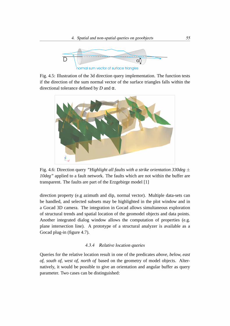
4. Spatial and non-spatial queries on geoobjects 55
D
normal sum vector of surface triangles
Fig. 4.5: Illustration of the 3d direction query implementation. The function testsif the direction of the sum normal vector of the surface triangles falls within thedirectional tolerance defined byD andα.
Fig. 4.6: Direction query”Highlight all faults with a strike orientation 330deg±10deg” applied to a fault network. The faults which are not within the buffer aretransparent. The faults are part of the Erzgebirge model [1]
direction property (e.g azimuth and dip, normal vector). Multiple data-sets canbe handled, and selected subsets may be highlighted in the plot window and ina Gocad 3D camera. The integration in Gocad allows simultaneous explorationof structural trends and spatial location of the geomodel objects and data points.Another integrated dialog window allows the computation of properties (e.g.plane intersection line). A prototype of a structural analyzer is available as aGocad plug-in (figure 4.7).
4.3.4 Relative location queries
Queries for the relative location result in one of the predicatesabove, below, eastof, south of, west of, north ofbased on the geometry of model objects. Alter-natively, it would be possible to give an orientation and angular buffer as queryparameter. Two cases can be distinguished:

4. Spatial and non-spatial queries on geoobjects 56
Fig. 4.7: Example of structural analyzer integrated with Gocad.
1. ”Select the geoobjects which completely have a relative location P togeoobject A.”That implicates that all vertices of the queried geoobject needto have a relative locationP with respect toA.
2. ”Select the geoobjects which are at least partly have a relative location Pwith respect to geoobject A.”That implicates that at least one vertex of thequeried geoobject needs to have a relative locationP with respect toA.
4.4 Queries based on geological and numerical properties
Property queries are based on the non-spatial properties associated with a geoob-ject. Besides spatial queries, these can provide an important aid to select subsets,reclassify or analyze 3d geomodels. In common 2d GIS like ArcGIS [2], non-spatial properties are stored in a relational database. Here, a SQL-based querylanguage is used for the selection of objects according to their properties, like thegeological age or the type of rock, for example.With the object-oriented topological data model used in this work, properties can

4. Spatial and non-spatial queries on geoobjects 57
Fig. 4.8: Simple example of a legend in Gocad. It allows to visually query 3dgeoobjects by geological properties.
be declared as variables of topological elements building a geomodel. These canbe queried within the Gocad geomodeling software and at the database. Apartfrom a query language, also graphical methods exist to select geoobjects based ontheir properties. Such map legends can also be used for a 3d geomodeling applica-tion and have been implemented as simple prototype in Gocad, where geoobjectscan be selected in a legend list by their age or rock type (figure 4.8).
Geoobjects. All non-spatial geological data of a geoobject declared in the datamodel in section 3.2.2, like stratigraphic age interval, fault type, and meta-dataare properties of a whole geoobject. This facilitated the development of Gocadfunctions to select geoobjects based on these properties. Query terms may becombined using boolean expressions.
Observation and model points. The discrete cells of geoobjects can carry prop-erties:
• at the vertices of triangulated surfaces or tetrahedric volume models (in Go-cad:SolidModel). In the data model provided in section 3.2.2, vertices canbe either ofModelPoint or ObservationPoint type.
• at then-cells of a GMap model. As shown by Levy et al. [30], the GMapapproach allows to associate properties to alln-dimensional cells of a GMapmodel. This can provide the basis for property modeling and query meth-ods within a sound combinatorial topological model. This work, however,examines query functionality on BRep models as described in section 3.2.2.
Properties of vertices can be queried by picking them visually, or by query func-tions. For numerical properties, query functions can be formulated in Gocad with

4. Spatial and non-spatial queries on geoobjects 58
the help of an comprehensive script language. From the query result, a subset ofvertices can be defined as a region and be treated separately. However, in Go-cad no distinction is made between model points and observation points. Here,extended vertices named ”Atoms” store the geometrical, numerical property, andconstraint information. Commonly, input data points are defined as control nodesand thus act as constraints for geometrical and property interpolation. They donot contain geological information.Geomodeling software users often build geomodels based on input data points.These correspond toObservationPoints presented in section 3.2.2.2. For usersit would be advantageous if they could access all available information associatedwith the input data points directly from the geomodeling software. Two benefitscan be delineated:
1. Distinction is made between interpolatedModelPoints andObservation-Points as input data. Thereby it is possible to state on which information ageomodel is based on.
2. All information stored with anObservationPoint becomes available dur-ing the geomodeling process and during the interpretation.
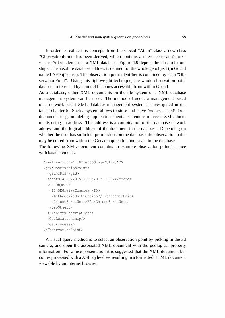
4. Spatial and non-spatial queries on geoobjects 59
In order to realize this concept, from the Gocad ”Atom” class a new class”ObservationPoint” has been derived, which contains a reference to anObser-
vationPoint element in a XML database. Figure 4.9 depicts the class relation-ships. The absolute database address is defined for the whole geoobject (in Gocadnamed ”GObj” class). The observation point identifier is contained by each ”Ob-servationPoint”. Using this lightweight technique, the whole observation pointdatabase referenced by a model becomes accessible from within Gocad.As a database, either XML documents on the file system or a XML databasemanagement system can be used. The method of geodata management basedon a network-based XML database management system is investigated in de-tail in chapter 5. Such a system allows to store and serveObservationPoint-documents to geomodeling application clients. Clients can access XML docu-ments using an address. This address is a combination of the database networkaddress and the logical address of the document in the database. Depending onwhether the user has sufficient permissions on the database, the observation pointmay be edited from within the Gocad application and saved in the database.The following XML document contains an example observation point instancewith basic elements:
<?xml version="1.0" encoding="UTF-8"?>
<gtx:ObservationPoint>
<gid>ID12</gid>
<coord>4589220.5 5639520.2 390.2</coord>
<GeoObject>
<ID>OEGneissComplex</ID>
<LithodemicUnit>Gneiss</LithodemicUnit>
<ChronoStratUnit>PC</ChronoStratUnit>
</GeoObject>
<PropertyDescription/>
<GeoRelationship/>
<GeoProcess/>
</ObservationPoint>
A visual query method is to select an observation point by picking in the 3dcamera, and open the associated XML document with the geological propertyinformation. For a nice presentation it is suggested that the XML document be-comes processed with a XSL style-sheet resulting in a formatted HTML documentviewable by an internet browser.

4. Spatial and non-spatial queries on geoobjects 60
Atom
ObservationPoint
+ IDREF : int
MyGObj
+ DataBase : string
GObj
Fig. 4.9: Simplified UML class diagram of the Gocad implementation of classOb-
servationPoint. In Gocad,GObj is the base class of modeler objects includingsurfaces, lines, points sets.
4.5 Geological queries using regular grid geomodels
Grid models provide the possibility of fast property queries and computations.Property queries may be supported by geometric and topological parameters. Forinstance, such queries are applicable in predictive mineral exploration sensitivitystudies.The query”Select all sets of connected grid cells with a certain electrical resis-tivity value. The sets should have a certain minimum number of elements.”is acombined topological and property query. In Gocad, non-spatial property queriesare possible to formulate using a functional script language. Spatial queries canbe computed on the grid cells, and the return value is assigned as a property to thecells. That way spatial queries can be transferred to property queries as demon-strated in figure??.
Geoobjects in grid models. A different concept for querying geoobjects must beused for grid models than for BRep models. Here, the property values are notassigned to an identifiable geoobject but are defined as a discrete property for awhole geological volume. Such a property may be the assignment of a cell toa certain geoobject. In Gocad it is possible to transfer the membership propertyfrom BRep model region to a grid model based on the location of the cells. Usingthis geoobject membership property, the geometry of geoobjects is defined in thegrid model and can be used in property queries.Geophysical data can be integrated into a geomodel. It is common practice to
4. Spatial and non-spatial queries on geoobjects 61
derive the geometry of geological structures from 2d or 3d seismic models. Also,it is possible to compute 3d models for the gravity, electric and magnetic potentialfields from measurements. Functionality for inverse and forward modeling ofgeophysical potential fields is available as plug-in for the Gocad geomodelingsoftware [8, 13]. This provides a novel approach for studying the relationshipbetween geological and geophysical models, and thereby validate the models witheach other.
4.6 Combining a set of geomodels
In 2d GIS, the combination (also named overlay) of several map layers based onthe geometrical co-location is a common procedure for the analysis of raster andvector maps. Transferred to a 3d GIS, this means to combine the topological, ge-ometrical, and property information of a set of geomodels. This task seems to behardly required if a geomodel - per definition - tries to respect all data available re-lated to a set of geoobjects [34]. On the other hand, multiple geomodels from oneinput data set are commonly created by stochastic simulations, or to test structuralgeological scenarios using as set of different structural models. However, hereeach model is built based on the same data set and independently valid accord-ing to the modeling criteria. For example, an intersection of two BRep-modelsrepresenting a structural situation differently is not useful, as the resulting modelis likely to be geologically and topologically inconsistent, and the geological se-mantic of resulting regions is not clearly defined. This arises from the fact thatin a geoobject-oriented model the regions are coincident with geoobjects, and theidentity of the geoobjects becomes undetermined.If geomodels with different properties exist or if different topological subdivi-sion should be compared, it is suggested to combine these models using a high-resolution regular grid. That way, grid models and tessellated cellular models canbe combined with the advantage that all property information can be examined inone model, and multivariate relationships can be detected. The problem of geoob-ject identity can be solved by assigning a membership function to the cells. InGocad, this information can be transferred from a BRep model to the grid model.The disadvantage is that the topological information of a BRep model cannot betransferred to the grid. Due to this fact, a maximum of information can be modeledby maintaining both a grid model and a structural topological geomodel.

4. Spatial and non-spatial queries on geoobjects 62
4.7 Query application - examples
4.7.1 Geomodel subset selecting
A common spatial data mining task is to select subsets of the database using con-ditioned queries. For a geological 3d GIS, topological query conditions are ofparticular interest because many geological relationships are coincident with topo-logical relationships, and can be discovered by topological queries. For this typeof query both the topological and the semantic information of the geoobjects areused to formulate queries on a set of geoobjects:
• ”Select all model volume regions which are neighbours to region R.”Theresult set contains all regions whose topological border at least partiallyoverlaps with the border of region R (figure 4.10).
• ”Select all model volume regions which are bound only by region R.”Forexample, this query can be used to select stratigraphic lenses which arebound by region R.
• ”Select all fault surfaces which intersect fault surface F.”The result setcontains all faults whose interior partially overlaps with fault F.
• The query ”Select the neighbouring regions of the selected loops” can helpto discover geological relationships. If, for example, the occurrence of askarn ore deposit is highly probable at the intersection of an hydrothermaldike and the lower boundary of a limestone horizon, it is possible to posethe inverse query and select the edges where hydrothermal dike boundaryfaces and lower boundary faces of limestone horizons meet.
• ”Select all surfaces with free edges.”In combination with relative geologi-cal age data this can be used to detect false fault geometries.
• ”Select all wells which intersect a certain horizon.”
4.7.2 Spatial and geological consistency checks
Topological integrity checks. Point set topological consistency checks can beused to check the integrity of a geomodel. By definition, in a single geomodeleach point must belong to the interior of one geoobject. An exception are fuzzyrepresentations, here the cumulative membership function must be equal to 1. Thefollowing statements illustrate the usage of this topological separation constraint:

4. Spatial and non-spatial queries on geoobjects 63
Fig. 4.10: Topological query to a volume model: ”Select all neighbour regionsof regionR (red color).” Because the topology is explicitly defined, queries forneighbourhood relationships and connectivities can easily be answered.
• If a point belongs to multiple geoobjects then an inconsistency occurs, likecrossing of strata. In cellular models including BRep models however, thiscannot happen if each spatial region is coincident with one geoobject. Ingrids, this problem can be avoided by defining geoobjects based on a mem-bership function, which may allow fuzziness.
• There exists only one universe region. Any other point must be contained ina geoobject of the geomodel. Otherwise there are holes in the model. In aBRep model this implies that each region should coincide with a geoobject.
Topological queries also allow to check the validity of a topological model againstthe geometrical model. In the case of a radial-edge BRep model this implies thattwo regions may only meet at their shared boundary faces, two faces at their sharedloops, and two loops at their shared vertices.
Spatial-geological consistency checks. Especially relative geological age andgenesis data can be combined with topological data to formulate constraints. Such
4. Spatial and non-spatial queries on geoobjects 64
a constraint is used in Gocad when building BRep model objects from a set of sur-faces. Here, geological information is used to correctly name stratigraphic layerregions after their top surface, unless the top boundary is of intrusive origin. Thefollowing list contains a list of examples of spatial-geological integrity checks:
1. age and intersection relationships
• Older faults may not intersect younger stratigraphic horizons.
• Younger faults may not be juxtaposed by older faults.
2. age, feature type and superposition relationships
• According to the law of superposition [41], in general older strati-graphic layers may not exist below younger stratigraphic layers (ex-ceptions: normal or thrust fault, overturned fold).
4.8 Implementation features
The query functionality presented in the previous sections has been implementedprototypically in a Gocad plug-in. Table 4.3 lists the developed spatial query func-tions. The plug-in has been programmed platform-independent in C++ and usesthe Qt widget library (Trolltech AS, Oslo) and Gocad.The user dialog shown in figure 4.11 provides an interface for comfortable, inter-active formulation of complex queries on Gocad objects. They can be combinedwith queries for geological information using set theoretic operators. By com-parison, the current version of the most widely used 2d GIS, ArcGIS version 8.3,allows spatial and geological attribute queries only successively to be posed forgeographical features.

4. Spatial and non-spatial queries on geoobjects 65
Fig. 4.11: Dialog for query functions in Gocad. First a target geoobject or regionis selected, then different queries can be combined and applied. In the examplemodel, a target objectlimestoneBis queried if it is connected withsandstoneAbyfaultA. An output window tracks the selected query terms and results.

4. Spatial and non-spatial queries on geoobjects 66
Query function Return Type Description
disjoint, equal, neighbour-hood, intersect, inside(GeoObject A)
List<GeoObject> returns a list of GeoObjects witha given topological relationshipwith the argument GeoObject
neighbourhood, inside (Re-gion A)
List<Region> returns a list of BRep-model re-gions with a given topologicalrelationship with the argumentregion
connected (Region A, RegionB, Boundary C)
boolean test if two BRep-model regionsare connected by a given bound-ary (fault-)surface
intersected (Boundary B) List<Layer> returns a list of BRep-model lay-ers which are intersected by agiven boundary (fault-)surface
buffer (bufferType, distance,GeoObject)
List<GeoObject> returns the GeoObjects locatedwithin the buffer of the argumentGeoObject. The first argumentallows to choose if the objectsmay intersect or need to be com-pletely within the buffer.
distance (distanceType,GeoObject, GeoObject)
float returns the distance between twoGeoObjects. The first argumentallows to choose euclidean min-imum or maximum distance
relativeSituation(GeoObject,direction)
List<GeoObject> returns a list of GeoObjects lo-cated in the given direction ofthe argument GeoObject
orientationBuffer(direction,angle, curv)
List<GeoObject> returns a list of GeoObjects witha mean extension in the given di-rection and buffer angle. ”curv”is a coefficient for filtering roughand curvilinear GeoObjects.
Tab. 4.3: List of spatial query functions developed and implemented as a Gocad plug-in.

5. DATA MANAGEMENT FOR 3D GIS - DESIGN ANDIMPLEMENTATION
5.1 Introduction
For 3d geomodeling projects a large amount of geodata needs to be stored andserved to multiple users during a long period of time. Commonly, geologicaldatabases are maintained for decades. Therefore, for 3d GIS projects it is essentialto have an efficient and reliable data management.After a review of existing methods for spatial geodata management, a novelmethod for 3d geodata storage and query is presented in this chapter. As pointedout in section 2.3, from the current perspective XML-based data managementcan provide an efficient means for long-term availability of geodata. Two specificrequirements must be honoured by the database server:
1. to store observation point data and geomodels as valid XML documentsaccording to the data model defined by XML Schemas, and
2. to provide geological and spatial query functionality from user applicationslike Gocad against the database.
5.1.1 Summary of existing approaches to spatial geodata management
2d spatial data in relational and object-relational databases. Several object-relational database systems offer support for primitive 2d spatial data types.Examples of such systems are Oracle and PostgreSQL [38]. These databases canstore geometrical primitives in relational tables. This technique is also used incommon geoinformation systems like ArcGIS. Here, the ArcSDE spatial databaseengine acts as an interface between the application software components and re-lational database systems. 2d GIS objects have a relatively flat data structurecompared to topological 3d geoobjects. For 2d geometrical objects the mappingto relational structures can be efficient.Guting [24] developed an georelational algebra based on 2d-spatial geometric
5. Data management for 3d GIS - design and implementation 68
object types. This approach can enable geometrical and topological query supportby the implementation language of the database system [24]. Recent spatialdatabases, like Oracle 9i Spatial, provide support for 2d spatial queries.
3d spatial data in object oriented databases. The concept of a georelational al-gebra [24] was extended by Breunig [9] to support 3d geometrical objects. Thisalgebra acts on so-called extended simplicial complexes (abbreviated: ”e-com”).It does not consider high-level topological data types like BRep models. However,the storage and query of such models is important for geological modeling. Theextension of the e-com algebra by the support of high-level topological modelscould provide a sufficient algebra for 3d spatial query processing.During the ”GeoStore” project [10] the storage of 3d geoobjects in an object-oriented database has been examined. Although it allows the persistence of com-plete geoobjects, this approach is not used in the geomodeling community. Thismight be due to the fact that users are forced to use an uncommon, proprietarydatabase system.
File based geomodel storage. Currently, geomodeling software packages includ-ing Gocad solely offer file based storage of geomodels. For example, in Gocadtwo ways of file based data storage are implemented:
1. import and export of selected objects as ASCII-files
2. import and export of all objects of a Gocad session as binary project file
The two Gocad formats allow to store the geometrical, topological, property andgraphical appearance information of all application objects including point sets,polylines, triangulated surfaces, Weiler-models, wells, and grids. For Gocad andcomparable geomodeling systems, no efficient geomodel storage approach usinga database management system with standard interfaces is available.
5.1.2 Spatial data in document centric object oriented data bases - XML
Geodata management based on XML is a solution meeting the requirementsstated in chapter 2.3. Functionality for the storage of both data-centric geomodelsand document-centric geological descriptions can be implemented using a nativeXML database server. A native XML database is a database that has a XMLdocument as its fundamental unit of logical storage and defines a logical datamodel for a XML document. It stores and retrieves documents according to that

5. Data management for 3d GIS - design and implementation 69
model. The logical model can be defined using the XML Schema language. TheXML Schema documents can be used to validate the integrity of data. Currently,the ”Tamino” native XML database by Software AG is the only mature productwhich is in use for large-scale industry projects. Besides Tamino, several XMLdatabase development projects exist, for example ”Xindice” by the Apache group(www.apache.org). Key advantages compared to relational database systems are:
• Native XML databases are most suitable for the storage of document-centric XML data. This relates back to their respective data structures: thetree/node hierarchy versus open, tabular data entities. When working withdocuments, as opposed to pieces of data, queries typically will result inlarger amounts of data being requested. XML-aware content indices canprovide a faster data retrieval mechanism when a large amount of documentdata is requested. The parsing of large XML data constructs is faster thanthe equivalent processing required when retrieving and then assemblingthis information from a relational data source [18].
• Support of query technologies designed specifically for the XML represen-tation format. This opens the door to sophisticated query statements thatwould not be possible with many of the XML-enabled relational databaseplatforms [18].
• Native XML databases can be positioned alongside relational repositoriesas cache and pre-validator [18].
XML and relational databases. Native XML databases are designed to accom-modate and manage a XML document structure independently from its content.Being able to differentiate the actual data from markup, including processing in-structions and entity references, is beyond the ability of typical relational databaseplatforms [18]. For data-centric XML documents, however, relational databasesthat have been extended with XML support are still the way to go [18]. It shouldbe noted that data-centric XML support is provided by all major database systems,including Oracle 9i, IBM DB2, and Microsoft SQL Server. These systems can useXML as exchange format and map XML documents internally to relational struc-tures for storage. However, Oracle and Microsoft are currently developing a newgeneration of databases which support XML as a native data type.
Queries. For querying a XML database, the comprehensive query languageXQuery can be used. XQuery is a functional language where each query is an
5. Data management for 3d GIS - design and implementation 70
expression. XQuery expressions fall into six broad types:
1. path expressions: XQuery supports path expressions that are a superset ofthose currently being proposed for the next version of XPath, a graph-basedXML search language. The example query:
/gtx:GISTriXP[@ID="project1"]
/gtx:GeoModel[@ID="model1"]
//gtx:observationPointRef
selects all observationPointRef elements which are contained in”model1” of ”project1”.
2. Element constructors: In some instances, it is necessary for a query to createor generate new elements. Such elements can be embedded directly into aquery in an expression called an element constructor.
3. A FLWR expression is a query construct composed of FOR, LET, WHERE,and a RETURN clauses. A FOR clause is an iteration construct that bindsa variable to a sequence of values returned by a query (typically a pathexpression). A LET clause similarly binds variables to values. A WHEREclause contains one or more predicates that are used on the nodes returnedby preceding LET or FOR clauses. The RETURN clause generates theoutput of the FLWR expression.
4. A conditional expression evaluates a test expression and then returns one oftwo result expressions. If the value of the test expression is true, the valueof the first result expression is returned; otherwise, the value of the secondresult expression is returned.
5. Quantified expressions: XQuery has constructs that are equivalent to quan-tifiers used in logic. The SOME clause is an existential quantifier used fortesting to see if a series of values contains at least one node that satisfies apredicate. The EVERY clause is a universal quantifier used to test to see ifall nodes in a series of values satisfy a predicate.
6. Expressions involving user defined functions: Besides providing a core li-brary of functions similar to those in XPath, XQuery also allows user de-fined functions to be used to extend the core function library.

5. Data management for 3d GIS - design and implementation 71
The most comprehensive XQuery language (www.w3.org/TR/xquery) implemen-tation currently exists for the Tamino database. XQuery has become an ISO andW3C standard in 2003. Using the XML Schema spatial data model defined in thisthesis, spatial queries which are based on explicitly defined topology and geome-try can be answered with the Tamino XQuery implementation.
• Queries based on the bounding box geometry of the geoobjects includethe following: inclusion, exclusion, and intersection. The bounding boxis stored as pre-computed element of geoobjects. For example, the set ofobservation point referencesobsof aBSurfModel which are located withina cuboid bounding box can be queried using a FLWR-expression:
FOR $obs IN
/gtx:GISTriXP[@ID="project1"]/gtx:GeoModel[@ID="model1"]
//gtx:observationPointRef
WHERE $obs/gml:coord/X>23000 AND $obs/gml:coord/X<63000
AND $obs/gml:coord/Y>37000 AND $obs/gml:coord/Y<223000
AND $obs/gml:coord/Z>-1000 AND $obs/gml:coord/Z<1000
RETURN $obs;
• Queries based on explicitly defined topological relationships of a BRep-geomodel can be computed. The set of neighbour regionsreg of a BSurf-
Model regionRcan be obtained by the quantified FLWR-expression:
FOR $reg IN
/gtx:GISTriXP[@ID="project1"]/gtx:GeoModel[@ID="model1"]
//gtx:modelRegion
WHERE SOME $bface IN $reg//gtx:bface SATISFIES
$reg//$bface = R//$bface
RETURN $reg;
However, for requests requiring more demanding computational geometry algo-rithms a standard database query language like XQuery is not sufficient. Com-monly required algorithms, like coordinate transformations and graph-based topo-logical queries, have a linear computational complexity of O(n). For geometricalalgorithms in 3d space, as for minimum distance computation between two trian-gulated surfaces, a computational complexity of O(n3) with a n>>1000 can occur.Such algorithms are not part of general database query languages. The ”X” in the

5. Data management for 3d GIS - design and implementation 72
”XQuery” stands for eXtensible, which suggest the possibility to add new func-tionality to the language which could process spatial computationally demandingqueries.
5.2 A new concept of a generic XML/component-based 3d GIS
The combination of all data management, geomodeling and query componentsconstitutes a 3d geoscience information system (figure 5.1). To prove the con-cept of a XML-based 3d GIS, a prototype system based on the following corecomponents and concepts has been developed and will be discussed in the nextsections:
• The data model defined using XML Schema language covers geomodelsand observation points as described in section 3.2.2. This data model deter-mines the common interface for the GIS software components. In order tofacilitate spatial database queries an extension for the XQuery language hasto be defined and implemented.
• Persistent data storage is realized using a XML database server. The na-tive XML database system Tamino provides the currently most comprehen-sive XML query language implementation based on the XQuery specifica-tion [48], and is available free of charge to developers and non-commercialusers. Therefore, Tamino has been chosen for this implementation. How-ever, other XQuery-supporting XML database servers can also be used.
• For spatial query processing, a middle-ware component between thedatabase and the user application is required. This can be an applicationserver which computes demanding 3d spatial XQuery requests.
• For communication between the GIS components XML documents are ex-changed using the HTTP protocol and the internet protocol (IP).
• XML database input and retrieval is possible from a set of XML-enabledclients, for example the geomodeling application Gocad.For geological observation data input, a method which generates HTMLforms automatically from XML Schemes has been developed. These formsare able to save the input data as valid XML documents. That way theobservation point data can be stored consistently in the XML database.

5. Data management for 3d GIS - design and implementation 73
spatialXQuery request
HTTP/IP
XML Data
XQuery request
HTTP/IP
XML Data
XQuery request
HTTP/IP
XML Data
3d XMLApplication Server
user applications• geomodeling
(geometry, topology, properties)• visualization• querying, analysis, prediction
XML databaseserver
• observations• geomodels
computing applications
mobile XML fielddata capturing
Fig. 5.1: Design of the 3d GIS framework. Queries can be posed from user appli-cations like Gocad. Standard XQuery requests can be sent directly to the database,while spatial XQuery requests are processed by an application server. The applica-tion server obtains the data of a project from the database and sends the computedresult set to the user application.
5.2.1 XQuery extension
A database containing sets ofBSurfModels, SolidModels, or separate surfacesand lines, often has no topology defined between these geoobjects. In that case,point set-theoretic spatial queries can be formulated and answered using topo-logical relationships computed from the geometry. The binary relationships dis-joint, equal, neighbourhood, intersect, outside, inside defined in section 4.2.1 needto be formulated in XQuery language and computed. Also, the altering topo-logical queries union, intersection, and difference, geometrical queries involvingdistance, volume, surface, buffer, relative situation, orientation, and geometricaltransformations may be performed using a spatially extended XQuery language.Table 5.1 shows the spatial XQuery functions which have been defined in an ex-tension XML schema document.
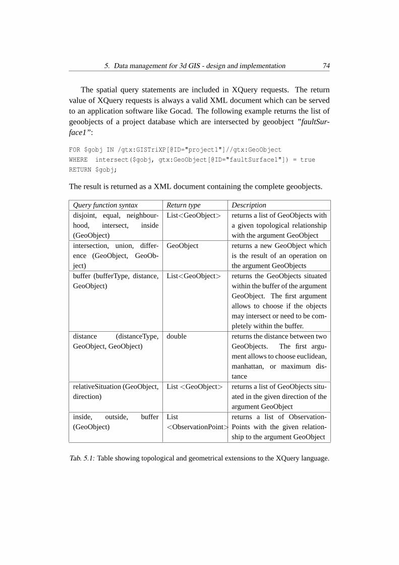
5. Data management for 3d GIS - design and implementation 74
The spatial query statements are included in XQuery requests. The returnvalue of XQuery requests is always a valid XML document which can be servedto an application software like Gocad. The following example returns the list ofgeoobjects of a project database which are intersected by geoobject”faultSur-face1”:
FOR $gobj IN /gtx:GISTriXP[@ID="project1"]//gtx:GeoObject
WHERE intersect($gobj, gtx:GeoObject[@ID="faultSurface1"]) = true
RETURN $gobj;
The result is returned as a XML document containing the complete geoobjects.
Query function syntax Return type Description
disjoint, equal, neighbour-hood, intersect, inside(GeoObject)
List<GeoObject> returns a list of GeoObjects witha given topological relationshipwith the argument GeoObject
intersection, union, differ-ence (GeoObject, GeoOb-ject)
GeoObject returns a new GeoObject whichis the result of an operation onthe argument GeoObjects
buffer (bufferType, distance,GeoObject)
List<GeoObject> returns the GeoObjects situatedwithin the buffer of the argumentGeoObject. The first argumentallows to choose if the objectsmay intersect or need to be com-pletely within the buffer.
distance (distanceType,GeoObject, GeoObject)
double returns the distance between twoGeoObjects. The first argu-ment allows to choose euclidean,manhattan, or maximum dis-tance
relativeSituation (GeoObject,direction)
List <GeoObject> returns a list of GeoObjects situ-ated in the given direction of theargument GeoObject
inside, outside, buffer(GeoObject)
List<ObservationPoint>
returns a list of Observation-Points with the given relation-ship to the argument GeoObject
Tab. 5.1: Table showing topological and geometrical extensions to the XQuery language.
5. Data management for 3d GIS - design and implementation 75
5.2.2 Design of the new data management system
Component-oriented query computation A new approach for computations ofhigh complexity on spatial geodata in XML format is required. This cannot berealized using a standard database query language. Instead, queries should beanswered with the support of an application server because of the following argu-ments:
• Spatial query requests with high computational demands have to be com-puted. The required algorithms have a complexity≥O(n) and cannot beformulated efficiently by the means of a query language.
• Data base management systems offer API’s (Application Programming In-terfaces) to improve the functionality of the query language and the func-tionality of the database server. For example, using the Tamino XTensionAPI in order to enhance the XQuery functionality would be a possible so-lution. This allows to develop computational algorithms in a performantCOM-enabling programming language. However, the development of aGIS adapted to a proprietary database programming interface would makethe system dependent on one proprietary database management system.
• Following the data independence paradigm, in information systems the ap-plication logic is commonly separated from the database server. This canbe achieved by the means of an application server. The application servercommunicates with user-application clients, and manages the data retrievalfrom the database and the computation of requests. Such an architecturecan be used to provide a flexible three-tier GIS environment (figure 5.1).
• Several application servers are currently in use, for example IBM Web-Sphere [39] and Oracle AS [45]. They are designed for e-business and cancope with>10 requests/second, which is far more than required for servinga 3d GIS community with less than 1000 users.On the other hand, their interfaces support applications written in inter-preted languages and scripts, like Java, .Net, and PHP. These languagesare not optimized for efficient processing. However, efficient processingis required for efficient spatial numerical and algebraic computations ofhigh complexity>O(n) and a typical data volume of>>1MB. A high-performant application server with a C++ API is suggested.
5. Data management for 3d GIS - design and implementation 76
• A component-based information system with standardized exchange proto-cols and formats can be used in a distributed computing environment. Forexample, spatial computing applications can run on a remote computer andact as clients for an application server [21]. This method frees processing re-sources for the application server and the database server. Such a distributedsystem allows an efficient geodata management if high computational de-mands exist.
• For high performance data access the application server should offer adatabase driver API for custom database driver development. This willallow to use the application server with different XML database systems.
Implementation features. The design of the data management and query pro-cessing suggested in this thesis has the following characteristics (see figure 5.1):
• An application server, named ”XAppS”, is located between user applicationclients like Gocad and a XML database. It offers programming interfacesfor both computing applications named ”XApp” and database drivers.
• XML database support. Currently, only the XML Server Tamino by Soft-ware AG is supported. However, the prototypical application server imple-mentation [21] offers a ATL/COM-based driver programming interface tointegrate further database management systems. The interface abstracts thefunctionality for:
1. Initiating and terminating a database connection session.
2. Requesting, storing and updating XML data.
3. Transactions including commit and rollback.
• XAppare fast software components which compute query results. The in-tegration of distributed applications is possible but not supported by theprototypical version [21].
• A Gocad plug-in has been developed as a client-side interface which allows
1. to formulate and send extended XQuery requests to the applicationserver (standard XQuery requests can be posed directly to the databaseserver),
5. Data management for 3d GIS - design and implementation 77
2. to receive responses from the application server or from the databaseserver,
3. and to generate native Gocad application objects from the XML rep-resentation.
• For data transfer with user application clients and databases, the applicationserver uses XML documents via HTTP. That way, the database and com-puting applications may run on other machines than the application server.
• Not every request of the Gocad client to the database is served by the ap-plication server. Only requests which are formulated using extended spatialXQuery operators (see table 5.1) are computed by aXApp called by theapplication server.
• due to its generic design theXAppSis not limited to 3d spatial computa-tions but can be used to solve any computationally demanding requests, ifappropriate computing applications are provided.
Architecture of the application server. The design of the internal architectureand the prototype implementation of theXAppShas been realized by T. Frank[21]. TheXAppSconsists of software components which interact using ATL/COMinterfaces [21]. This allows to use a generic software design including templates.All components of theXAppSwere programmed in C++. Figure 5.2 shows themain components of the new application server (after [21]):
• Request Server: TheXAppSis receiving requests from clients and returnsthe results to them.
• Parser: The Xerces C++ parser is used to convert XML elements into C++objects.
• Manager: TheXAppSconfiguration is stored in a XML file. The Manageruses this file to extract the server settings used at server startup.
• Server Engine: The Server Engine integrates the single components to theXAppSapplication. It includes the logic for both the standalone and thesystem service version of theXAppS. Both versions are realized within oneexecutable.

5. Data management for 3d GIS - design and implementation 78
• Application Dispatcher: The Application Dispatcher loads the appropriateXAppand dispatches the client request to this application.
• XAppAPI: application programming interface for the communication withXAppcomputing applications
Fig. 5.2: Design of the XML application server (from [21])
How are XQuery requests processed? Spatial XQuery request can be sent to theapplication server by an application software like Gocad. Gocad has a client-sideinterface which features a query user dialog, and functionality to wrap a XQueryin a XML request document. Besides the XQuery, the request includes the logicaldatabase address and the name of the processingXApp. The name of the requiredXApp is obtained by parsing the XQuery request and searching for spatial queryfunctions.This request is interpreted by the application server, and required geomodel data

5. Data management for 3d GIS - design and implementation 79
are thereupon obtained from the database. The application server calls then aspecified application, which computes the result set. The result will subsequentlybe sent to the requesting application. Figure 5.3 shows an example user dialog,which allows to retrieve Gocad-objects in XML format from a database server.Alternatively, if no spatial query operator is contained in the request, the XQuerymay also be sent directly to the XML database server. Also, XML documentscontaining Gocad objects may be stored and retrieved using the file system.The Gocad client-interface has been implemented in C++ and is platform-independent.
Fig. 5.3: Query dialog in Gocad: a database and driver is specified, and a XQueryis formulated. The parameters are wrapped in a XML request document and sentto theXAppSvia HTTP. The result is returned as XML document to Gocad, andsubsequently converted into Gocad objects. In this example, the line of a surfaceintersection is returned.
5.2.3 XApp - applications to compute the result of XQuery requests
XAppapplications are called by the application server using a request documentin XML format containing data and - if required - function parameters for query

5. Data management for 3d GIS - design and implementation 80
processing.Many queries based on implicit topology can be answered using geometrical in-tersection tests. Two example spatial query operators from table 5.1 were cho-sen as exampleXAppapplication: intersect(GeoObject, GeoObject) and intersec-tion(GeoObject, GeoObject), which return a boolean result or a new geoobject,respectively. The implementation has been realized in C++ in cooperation with T.Frank [21].
Algorithms. To compute the results of 3d geometrical and topological XQueryrequests, several algorithms are available. Computing algorithms for queries on3d simplicial complexes have been extensively studied by Breunig [9]. Algo-rithms for queries on macro-topological geomodels and directional queries havebeen discussed in sections 4.2.2 and 4.3.3. TheXAppapplications can call APIfunctions implemented in user application software. In particular, algorithms im-plemented in Gocad have been used for the development of test applications.
Example: XApp.intersection. The example query”Select the intersection linesof all surfaces of a project which withfaultSurface1.” can be formalized in XQuerylanguage
FOR $gobj IN /gtx:GISTriXP[@ID="project1"]//gtx:GeoObject
WHERE $gobj = intersection($gobj, gtx:GeoObject[@ID="faultSurface1"])
RETURN $gobj;
and answered using the applicationXApp.intersection. This application tests thegeoobjects for intersection and returns the intersection polylines. The applica-tion dispatcher (figure 5.2) launches theXApp.intersection. It contains a functionServeRequest()which covers the core application logic (figure 5.4). First, thisfunction retrieves the required data from the database. TheIntersect()algorithmthen tests whether the geoobjects intersect. For this example, an external Gocadfunction for intersection test is called. This Gocad function is based on a recursiveoctree computation and octree traversal for common cells.
5.3 Discussion
The data management is a core component of the 3d GIS framework presented inthis work. The approach provided here fulfills the requirements stated in section2.3. Major steps and contributions are:

5. Data management for 3d GIS - design and implementation 81
Fig. 5.4: UML diagram of the example computing application XApp.Intersection(from [21]).
1. Design and implementation of an example XML database according to the3d spatial XML schema data model described in section 3.2.2.
2. Extension of the XQuery language with a set of spatial query operators for3d geoobjects. This was necessary because computationally demanding,complex spatial queries cannot be solved by the means of a standard querylanguage like SQL or XQuery.
3. Development of a concept to answer non-spatial and simple spatial requestsdirectly using XQuery, and computationally demanding spatial queries us-ing a middle-ware between the user application and the DBMS. In this ex-ample implementation, such spatial queries are posted from a Gocad ap-plication, and computed by fast C++ applications called by an applicationserver.
Besides the capability to handle spatial XML data, a main advantage of the devel-oped system is its genericity. This can be characterized by the following facts:
• It allows to integrate further databases capable of storing XML-documents.This follows from the application server driver API [21].

5. Data management for 3d GIS - design and implementation 82
• It allows not mere database selection queries, but the use ofXAppas toolsfor other computationally demanding data manipulations is possible, likefast data transformations, or down-sampling of tessellations for web-servingof geomodels.
• Due to the generic programming interfaces it is possible to integrate furtherdatabases in the information system, and to enable the usage within an het-erogeneous environment of GIS tools. Any geospatial application front-endcan be used together with the application server if appropriate computingapplications, data converters and client interfaces exist, for example:
– 2d GIS. Recent releases of large 2d GIS vendors support GML as dataexchange format, which eases the integration of such systems.
– web front-ends for observation data input, including mobile devices.For example, a HTML-based form prototype has been created whichallows to automatically save the form data as valid XML documentsaccording to the observation point schema. This facilitates the efficientand consistent observation data storage by field geologists.
– web front-ends for display of geomodels or raw data in XML format,including X3D for 3d visualization
The application server has been designed to compute set based requests on geospa-tial data stored in XML databases. The query result set is efficiently computeddirectly from the geoobjects in the XML database. The storage of an orientedbounding box (OBB) tree [23] with 3d geoobjects along with the usage of themethod of separating axes [23] for intersection tests may enhance the XML queryprocessing speed significantly. A conceptually similar approach is used by com-mon relational spatial database systems for 2D GIS-applications like the Oracle9 Spatial database. They rely on precomputed spatial indexes such as R-Trees tocompute fast search results.The performance of spatial XML query depends primarily on the database serverand can be optimized by the usage of indexes and efficient query formulation. Us-ing Tamino version 3.2, for indexed highly structured data, like triangulated sur-faces, the processing speed is 75-85% compared to common relational databaseservers [43]. For document-centric, semi-structured data like observation pointdescriptions the processing speed of native XML-databases is higher than theirrelational counterparts [18].

6. CONCLUSIONS
Summary of achievements. In this work, new technologies for a 3d geoscienceinformation system were developed. These result in a XML-based 3d GIS frame-work, which overcomes existing deficiencies in the current geomodeling softwareenvironment. Similar to common 2d GIS, the 3d GIS framework is not a single-component application. Instead it is a system integrating several software com-ponents based on a novel data model incorporating geomodels and geologicalobservation data. The main achievements are twofold:
1. For a GIS, querying is an essential part of data analysis. In this work, 3dspatial and geological query functions have been analysed and designedsystematically and subsequently implemented as a Gocad Plug-in. For ex-ample, functions for the selection of geoobjects of a 3d geomodel by theirtopological, geometrical, and geological properties have been made avail-able.
2. In order to improve the data management for geomodeling applications,a new concept which involves a XML database management system andwhich offers spatial query possibilities is suggested. A data model has beencreated in XML Schema language for geomodels and for geological ob-servation points. This allows to store observations and geomodels as validXML documents in a XML database. Data can be retrieved by Gocad orother applications via the internet by non-spatial or 3d spatial XQuery re-quests. For that purpose XQuery has been extended to include spatial op-erators. Spatial queries which are computationally demanding can be pro-cessed by a fast application server, which has been developed by T.Frank[21].
This 3d GIS framework is designed to support the data management and dataanalysis of large-scale 3d geological projects which usually incorporate large setsof spatial geological observations and 3d geomodels. The data management isdesigned to store and retrieve spatial sampling data, knowledge, concepts, and

6. Conclusions 84
models in an open, extensible, object-oriented, standard-conform way as XMLdocuments.The Gocad plug-in has been implemented in ANSI C++ [42], and relies solely onthe Gocad and Qt software libraries. Gocad is distributed by Earth Decision Sci-ences, Houston (http://www.gocad.com), and Qt is distributed by Trolltech SA,Oslo (http://www.trolltech.com). Both components are available for common op-erating systems including Microsoft Windows and Linux. The only platform-dependent component of the GIS framework is the Microsoft COM-based applica-tion server, while user applications and databases can run on any internet-enabledoperating system.
6.1 Critical reflections
As the title word ”framework” suggests, this is not a complete 3d GIS environmentcomparable to well-established, full-featured 2d GIS. This relates mainly to thefollowing points:
1. The XML Schema data model is limited to geological observation pointsand BRep geomodels. Additional data types, especially wells, need to behandled for many projects. For wells, no common industry standard existsto date. Thus custom solutions are needed.No XML storage is provided for grid models. It is suggested to add this infuture using the planned binary XML standard. Alternatively, the storage ofgrid data as binary large object (BLOB) in Gocad format is possible usingXML.
2. The spatial query functionality developed in this work is not intended tobe complete. Due to the many and very complex data types and the hugeamount of theoretically possible operations involved this is unrealistic andis often also not useful to implement. Instead, geological, geometrical, andtopological queries have been theoretically investigated, and a set of spatialand geological property queries which are considered useful for geologicalinvestigations has been implemented.
3. In contrast to 2d geographical data processing, geological data analysis andmodeling of complex geological scenarios is often a difficult task due to themany parameters involved, different geological concepts, and sparse data.In a sense, a geomodel can be considered as a highly probable assumption

6. Conclusions 85
of a geological situation based on observation data and geological concepts.Using geostatistical methods, Gocad also allows to model the spatial andproperty uncertainties associated with a geomodel. This model is, how-ever, a static one, and does not contain information about its geologicalgenesis in terms of its spatial and property changes through time. Many im-portant geological issues however are related to the genetic processes andrelationships and the structural and compositional evolution of a geologicalsituation. Such queries need to be handled by a spatio-temporal geoscienceinformation system which captures the evolution of geoobjects and theirrelationships in geological history.
4. The creation of large databases of geological observations and of complex,regional geomodels composed of a large number of geoobjects requires stillenormous efforts. Similarly, large 2d GIS projects including database cre-ation commonly need several years to be completed. For real-world use ofthe functionality developed here resulting in new geoscientific knowledge,a large database is required. For small models it is often appropriate to usesimply visual analysis and come to the same result as by a sophisticatedquery. For this work such a large database was not available. Instead, thefunctionalities implemented were tested separately using relatively smalldata sets.
The core user application, the Gocad geomodeling software, is a mature applica-tion but nevertheless continuously under development in terms of its functional-ity, and in the long-term probably also in terms of its data model. Therefore, theGIS framework needs to keep track with Gocad in order to be usable. The othercomponents, namely the XML database server, are also actively developed. Nev-ertheless the chances for a long usability of the GIS framework are high for to thefollowing reasons:
1. The data model and interfaces in this work are based on XML. The supersetof XML named SGML is an ISO standard since 1985, and XML itself,XQuery, and XML Schema are as well ISO standards. Due to their commonusage in the world wide web they are actively developed. This impliesthat this is not short-lived language but a mature, well-supported, long-termsolution for storing data as self-describing documents.
2. The triangulated radial-edge BRep topological data model used in Gocadand for XML storage is as well a stable, well studied data model. Other

6. Conclusions 86
approaches, like hierarchical GMaps [14] and the recently developed GMLstandard [22] for geographical data exchange, are convertible to this datamodel.Due to the usage of XML, the observation point and BRep-model data mod-els can easily be adapted to custom needs. This is facilitated by the object-oriented nature of the XML Schema language which is used for the datamodel definition: elements can be derived by extension or restriction, andnew elements can be created.The application server, as spatial database query processing component, hasbeen developed in a generic way. That means that it is possible to use it withother databases and user front-ends which are able to process XML. It canbe extended in functionality by developing new computing applications ina plug-in fashion.
6.2 Outlook
The following developments are suggested to extend the implementation of thesystem, or to make it more user-friendly:
• Completion of the implementation of the set ofXApp for 3d spatial XMLdatabase queries using the application server.
• Implementation of features for user-friendly formulation of complex, com-bined queries. This could be achieved by an interactive graph, where thenodes represent basic query operators. Similar approaches have been usedfor fourth generation programming languages, like the OpenDX data ex-plorer [36].
• Integrating artificial intelligence functionality. Probabilistic neural net-works have successfully been used for mineral potential mapping in 2dGIS [25]. Applying this methodology in to 3d geomodels may result, forexample, in intelligent prediction of 3d regions with high mineral potential.
• An interesting aspect is the usage of the application server within a spatio-temporal GIS. Because of the lack of common database management sys-tems to efficiently represent temporal information related to geoobjects, likegeometrical, topological, or non-spatial property changes, the applicationserver could be the way to add custom logic to the GIS.

BIBLIOGRAPHY
[1] Apel, M. 1999: 3D-Modellierung desostlichen Saxothuringikums. Unpubl.diploma thesis, TU Bergakademie Freiberg.
[2] ArcGIS user manual 2003, E.S.R.I., Redlands/CA.
[3] Bakker, P.: 2002: Image structure analysis for seismic interpretation. Ph.D.thesis, Delft University of Technology, ASCI Dissertation Series 78, Delft.
[4] Balovnev, O., Breunig, M., Cremers, A.B. 1997: From GeoStore toGeoToolKit: The second step. Proc. of the 5th International Symposium onSpatial Databases, Berlin, Germany, Lecture Notes in Computer Science, Vol.1262, Springer, p. 223-237.
[5] Bartl, S. 2003: XML Schemas fur geologische Daten und dreidimensionaleGocad-Modelldaten. Unpubl. diploma thesis, Technische Universitat Freiberg,46 p.
[6] Bishop, R. and Goldberg, S. 1980: Tensor Analysis on Manifolds. Dover,New York.
[7] Bonham-Carter, G.F. 2000: Geographic Information Systems for Geoscien-tists: Modeling with GIS. Pergamon Press, Oxford. 398p.
[8] Bosch, M., McGaughey, J. 2001: Joint inversion of gravity and magnetic dataunder lithological constraints. The Leading Edge 20, SEG, p. 877-881.
[9] Breunig, M. 1996: Integration of Spatial Information for Geo-InformationSystems. LNES No. 61, Springer Verlag. 171 p.
[10] Breunig, M. 2001: On the way to component-based 3D/4D GeoinformationSystems. LNES No. 94, Springer Verlag. 179 p.
[11] Brodaric, B. 1997: Field Data Capture and Manipulation Using GSC Field-log v3. US Geological Survey Open-File Report 97-269
BIBLIOGRAPHY 88
[12] Broome, J., Brodaric, B., Viljoen, D., Baril, D. 1993: The NATMAP DigitalGeoscience Data-Management System. Computers and Geosciences, vol. 19,no. 10, p. 1501-1516.
[13] Brottka, K. 2003: 3D Modellierung und Inversion in der Gravimetrie. Un-publ. diploma thesis, TU Bergakademie Freiberg.
[14] Conreaux, S., Levy, B., Mallet, J.-L. 1998: A cellular topological modelbased on generalized maps: The gocad approach. Gocad Meeting 1998 Pro-ceedings, Nancy, 17p.
[15] Eberly, D. 2001: Intersection of Convex Objects: The Method of SeparatingAxes. Documentation and C++ source code, http://www.magic-software.com.See attachment 1 (CD-ROM).
[16] Egenhofer, M., Franzosa R. 1991: Point-set topological spatial relations.International Journal of Geographical Information Systems, vol. 5, p. 161-174.
[17] Egenhofer, M. 1993: A model for detailed binary topological relationships.Geomatica vol. 47, Canadian Institute of Geomatics, p. 261-273.
[18] Erl, T.: Service-Oriented Architecture: A Field Guide to Integrating XMLand Web Services. Prentice-Hall.
[19] Euler, N. 1999: Modelisation volumique de reservoirs petroliers: construc-tions et mise a jour. PhD thesis, Institut National Polytechnique de Lorraine,Nancy.
[20] Fanchi J.R. 2002: Shared Earth Modeling: Methodologies for IntegratedReservoir Simulations. Gulf Professional Publishing.
[21] Frank, T. 2003: Design and Implementation of a 3d XML application server.Unpubl. M.Sc. Thesis, University Freiberg, 97 p.
[22] OpenGIS Geography Markup Language (GML) Implementation Specifica-tion v.3 2003, http://www.opengis.org. See attachment 1 (CD-ROM).
[23] Gottschalk, S., Lin, M.C., Manocha D. 1996: OBB tree: A hierarchicalstructure for rapid interference detection. Proceedings of ACM Siggraph’96.24 p.
BIBLIOGRAPHY 89
[24] Guting, R.H.: Geo-Relational Algebra: A Model and Query Language forGeometric Database Systems. In: Schmidt J.W. et al. (Eds.): Advances inDatabase Technology. Proc. of the Int. Conf. on Extending Database Technol-ogy, Venice, 1988, 506-527.
[25] Harris, D.P., Pan, G. 2000: Information Synthesis for Mineral Exploration,Oxford University Press.
[26] Kemp, E. de 2000: 3-D Integration and Visualization of Structural FieldData: Tools For Regional Subsurface Mapping. PhD Thesis, Universite duQuebec.
[27] Keskes, N. 1994: Image analysis techniques applied to 2D and 3D seismicdata. Proc. SPIE Vol. 2301, p. 111-116
[28] Labat, L., Shtuka, A. , Mallet, J.-L., Coureaud, B. 2002: Facies SimulationUsing Membership Functions and Multi P-Field. ECMOR VIII. Meeting Proc.,Freiberg, 8 p.
[29] Lepage, F. 2002: Triangle and tetrahedral meshes for geological models.Terra Nostra Vol. 4., IAMG Conference 2002 Berlin, p. 105-110.
[30] Levy, B., G. Caumon, G., Conreaux, S. 2000: TopoLab: A generic imple-mentation of G-Maps.
[31] Levy, B. 1999: Topologie Algorithmique: Combinatoire et Plongement.PhD thesis, INPL, Nancy.
[32] Lienhardt, P. 1994: N-Dimensional Generalized Combinatorial Maps andCellular Quasi-Manifolds. Journal on Computational Geometry and Applica-tions, volume 4, p. 275-324
[33] Malczewski, J. 1999: GIS and Multicriteria Decision Analysis. J. WileySons.
[34] Mallet J.-L. 2002: Geomodeling. Oxford University Press Monograph.
[35] Munkres, J. R. 1975: Topology: A First Course. Prentice-Hall, EnglewoodCliffs, NJ.
[36] Thompson, D., Braun, J., Ford R. 2003: OpenDX Paths to Visualization.Visualization and Imagery Solutions, Missoula, MT.
BIBLIOGRAPHY 90
[37] Paredaens, J., Van den Bussche, J., Van Gucht, D. 1994: Towards a theoryof spatial database queries. Extended abstract, Proc. 13th Symp. on Princ. ofDatabase Systems, Minneapolis, p. 279-288.
[38] Rigaux, P., Voisard, A., Scholl, M.O. 2002: Spatial Databases: With Appli-cation to GIS. Morgan Kaufmann.
[39] Sadtler, C. et al. 2003: IBM WebSphere Application Server - Express V5.0Handbook. IBM Redbooks.
[40] Soller, D.R., Berg, T.M. 1999: The National Geologic Map Database - AProgress Report; USGS Open File Report 99-386.
[41] Steno, N. 1669: De solido intra solidum naturaliter contento dissertationisprodromus. Florence.
[42] Stroustrup, B. 1987: The C++ Programming Language. Addison-Wesley ,Reading, MA.
[43] Tamino XML Server 3.1 White Paper 2003. Software AG,http://www.softwareag.com/tamino. See attachment 1 (CD-ROM).
[44] Unified Modeling Language (UML) Specification v.1.3 2003,http://www.omg.org. See attachment 1 (CD-ROM).
[45] Vandivier, S., Cox, K. 2002: Oracle9i Application Server Portal Handbook.Osborne ORACLE Press Series, Berkeley.
[46] Weiler, K. 1988: The radial edge structure: a topological representation fornon-manifold geometric boundary modeling. Geometric Modeling for CADApplications, Elsevier Science Publish., p. 3-36.
[47] eXtensible 3D Specification 2003, http://www.web3d.org. See attachment 1(CD-ROM).
[48] XQuery 1.0: An XML Query Language, W3C Working Draft,http://www.w3.org/TR/xquery. See attachment 1 (CD-ROM).
[49] Extensible Markup Language (XML) 1.0. W3C Recommendation 6/2000,http://www.w3.org. See attachment 1 (CD-ROM).
[50] XML Schema Specification, http://www.w3.org. See attachment 1 (CD-ROM).

LIST OF FIGURES
2.1 UML diagram of the top-level conceptual data model. Geoobjectsare inferred from observations by concepts. Edges denote associ-ation, diamonds denote aggregation. . . . . . . . . . . . . . . . . 8
2.2 Example of a boundary representation geomodel showing theErzgebirge region/ Germany. This large-scale crustal model isbased on geological and geophysical data and has been createdusing Gocad software. To examine such regional models, spatialand geological query functionality is required. . . . . . . . . . . . 9
3.1 BRep model hierarchy: A) volume decomposition, B) surface de-composition, C) border loop subdivision; a non-manifold condi-tion occurs on the horizon - fault contact line, D) triangulation . . 21
3.2 Radial edge topological elements. . . . . . . . . . . . . . . . . . 223.3 The radial-edge database uses the list of edge-uses, ordered ra-
dially about an edge to manage the manifold and non-manifoldfeatures. . . . . . . . . . . . . . . . . . . . . . . . . . . . . . . . 22
3.4 Example 2-GMap (A) with its incidence graph (B)[30] . . . . . . 253.5 Example 2-GMap with darts symbolized by bullet-headed seg-
ments, dotted lines stand for 0-functions, arcs of a circle corre-spond to 1-involutions, 2-links are represented by double lines [30]. 26
3.6 A sub-partitioned GMap surface (left), and a GMap model buildfrom sub-partitioned surfaces (right) [30]. . . . . . . . . . . . . . 26
3.7 Field representation of 5 geoobject regions filling a Gocad Voxet.2 sections are shown. (data courtesy Mira Geoscience Ltd.) . . . . 28
3.8 Simplified UML diagram of the spatial macro object model. Note:a "GISTriXP" project is an association of bothObservation-PointSet andGeoModels. Geomodels are associated withOb-servationPoints by aggregation (void diamond symbol), andwith ModelPoints by composition (filled diamond symbol). . . . 32
List of Figures 92
3.9 Simplified UML representation of the ObservationPoint datamodel. The top-level elements are shown in blue. Only top-levelassociations and attributes are depicted. . . . . . . . . . . . . . . 36
4.1 Querying the spatial relationships of observation points. A granitebody is symbolized in grey, the surrounding region is limestone.The query results are shown in color: granite observation pointsare red, limestone points are green. . . . . . . . . . . . . . . . . . 40
4.2 Topological relationships between two 3d topological regions ac-cording to the 9-intersection model. . . . . . . . . . . . . . . . . 44
4.3 A Gocad BRep model where two fault surfaces are intersecting,two are disjoint, two are touching, and all three are touching theterrain surface. The relationship computation between the trian-gles is accelerated by the octrees. . . . . . . . . . . . . . . . . . . 47
4.4 Highlighting the fault parts located within a distance buffer of an-other fault. The faults are part of the Erzgebirge model [1]. . . . . 53
4.5 Illustration of the 3d direction query implementation. The func-tion tests if the direction of the sum normal vector of the surfacetriangles falls within the directional tolerance defined byD andα. 55
4.6 Direction query”Highlight all faults with a strike orientation330deg± 10deg” applied to a fault network. The faults whichare not within the buffer are transparent. The faults are part of theErzgebirge model [1] . . . . . . . . . . . . . . . . . . . . . . . . 55
4.7 Example of structural analyzer integrated with Gocad. . . . . . . . 564.8 Simple example of a legend in Gocad. It allows to visually query
3d geoobjects by geological properties. . . . . . . . . . . . . . . . 574.9 Simplified UML class diagram of the Gocad implementation of
classObservationPoint. In Gocad,GObj is the base class ofmodeler objects including surfaces, lines, points sets. . . . . . . . 60
4.10 Topological query to a volume model: ”Select all neighbour re-gions of regionR (red color).” Because the topology is explicitlydefined, queries for neighbourhood relationships and connectivi-ties can easily be answered. . . . . . . . . . . . . . . . . . . . . . 63
List of Figures 93
4.11 Dialog for query functions in Gocad. First a target geoobject orregion is selected, then different queries can be combined and ap-plied. In the example model, a target objectlimestoneBis queriedif it is connected withsandstoneAby faultA. An output windowtracks the selected query terms and results. . . . . . . . . . . . . . 65
5.1 Design of the 3d GIS framework. Queries can be posed fromuser applications like Gocad. Standard XQuery requests can besent directly to the database, while spatial XQuery requests areprocessed by an application server. The application server obtainsthe data of a project from the database and sends the computedresult set to the user application. . . . . . . . . . . . . . . . . . . 73
5.2 Design of the XML application server (from [21]) . . . . . . . . . 785.3 Query dialog in Gocad: a database and driver is specified, and a
XQuery is formulated. The parameters are wrapped in a XMLrequest document and sent to theXAppSvia HTTP. The result isreturned as XML document to Gocad, and subsequently convertedinto Gocad objects. In this example, the line of a surface intersec-tion is returned. . . . . . . . . . . . . . . . . . . . . . . . . . . . 79
5.4 UML diagram of the example computing application XApp.Intersection(from [21]). . . . . . . . . . . . . . . . . . . . . . . . . . . . . . 81

LIST OF TABLES
3.1 Table of equivalent classes of topological model objects of theGocad, X3D, and GML data model. . . . . . . . . . . . . . . . . 35
4.1 Table showing a classification of spatial queries on geoobjects. . . 424.2 Translation between point set topological elements and Weiler
model elements. . . . . . . . . . . . . . . . . . . . . . . . . . . . 494.3 List of spatial query functions developed and implemented as a
Gocad plug-in. . . . . . . . . . . . . . . . . . . . . . . . . . . . 66
5.1 Table showing topological and geometrical extensions to theXQuery language. . . . . . . . . . . . . . . . . . . . . . . . . . . 74