WHITE-RODGERS - Emerson seau), faites inspecter celui-ci par un électricien, un entre-preneur...
8
Printed in U.S.A. PART NO. 37-4701C Replaces 37-4701B 0023 WHITE-RODGERS DIVISION EMERSON ELECTRIC CO. 9797 REAVIS RD., ST. LOUIS, MO. 63123 (314) 577-1300, FAX (314) 577-1517 9999 HWY. 48, MARKHAM, ONT. L3P 3J3 (905) 475-4653, FAX (905) 475-4625 TYPE 24A01 / 24A05 “SLIMLINE” LEVEL-TEMP SILENT OPERATOR (Normally Open) INSTALLATION INSTRUCTIONS Operator: Save these instructions for future use! FAILURE TO READ AND FOLLOW ALL INSTRUCTIONS CAREFULLY BEFORE INSTALLING OR OPERATING THIS CONTROL COULD CAUSE PERSONAL INJURY AND/OR PROPERTY DAMAGE. A.C. A.C. MOTOR INDUCTIVE TYPE INPUT THERMOSTAT RESISTIVE NUMBER VOLTAGE /FREQUENCY CURRENT NON-INDUCTIVE 24A01G-3 240VAC, 60 Hz 0.2A 25A, 6000W, 240V 12A, 240V 72A, 240V 24A01Z-10 347VAC, 60 Hz 0.2A 17A, 5900W, 347V 24A01Z-11 600VAC, 60 Hz 0.2A 12A, 7200W, 600V 24A05A-1 120VAC, 60 Hz 0.2A 25A, 3000W, 120V 16A, 120V 96A, 120V 24A05E-1 208VAC, 60 Hz 0.2A 25A, 5200W, 208V 12A, 208V 72A, 208V 24A05Z-1 277VAC, 60 Hz 0.2A 22A, 6000W, 277V FULL LOAD LOCKED ROTOR DESCRIPTION These “Level-Temp” controls have been designed to operate with a White-Rodgers low-voltage electric heat thermostat to provide a system for controlling electric warm air heaters and electric radiant heating devices such as duct heaters, wall heaters, baseboards, floor and ceiling cable heaters. When required, two or more Level-Temp Silent Opera- tors can be operated by one two-wire low voltage thermo- stat. The operator has been carefully adjusted. No attempt should be made to adjust it after it leaves the factory. If in doubt about whether your wiring is millivolt, line, or low voltage, have it inspected by a qualified heating and air conditioning contractor, electrician, or someone famil- iar with basic electricity and wiring. Do not exceed the specification ratings. All wiring must conform to local and national electrical codes and ordinances. This control is a precision instrument, and should be handled carefully. Rough handling or distorting compo- nents could cause the control to malfunction. Do not use on circuits exceeding specified voltages. Higher voltages will damage control and could cause shock or fire hazard. To prevent electrical shock and/or equipment damage, disconnect electric power to system, at main fuse or circuit breaker box, until installation is complete. CAUTION WARNING PRECAUTIONS SPECIFICATIONS ELECTRICAL DATA Switch Action: Single-Pole, Single-Throw, normally open Thermal: Average time delay – 45 seconds Ambient Temp.: -20° to 140°F (-24° to 60°C) Room Thermostat: Set adjustable heat anticipator at 0.2 Amps. For fixed anticipation thermostats, use 0.15 to 0.25 Amp. heater. WHITE-RODGERS Mounting: 1/2" conduit hub or mounting tabs with several break-offs for 2, 3 or 4 hole mounting
Transcript of WHITE-RODGERS - Emerson seau), faites inspecter celui-ci par un électricien, un entre-preneur...

Printed in U.S.A.
PART NO. 37-4701CReplaces 37-4701B
0023
WHITE-RODGERS DIVISIONEMERSON ELECTRIC CO.9797 REAVIS RD., ST. LOUIS, MO. 63123(314) 577-1300, FAX (314) 577-1517
9999 HWY. 48, MARKHAM, ONT. L3P 3J3(905) 475-4653, FAX (905) 475-4625
TYPE 24A01 / 24A05“SLIMLINE” LEVEL-TEMP
SILENT OPERATOR(Normally Open)
INSTALLATION INSTRUCTIONS
Operator: Save these instructions for future use!
FAILURE TO READ AND FOLLOW ALL INSTRUCTIONS CAREFULLY BEFOREINSTALLING OR OPERATING THIS CONTROL COULD CAUSE PERSONALINJURY AND/OR PROPERTY DAMAGE.
A.C. A.C. MOTOR INDUCTIVETYPE INPUT THERMOSTAT RESISTIVE
NUMBER VOLTAGE /FREQUENCY CURRENT NON-INDUCTIVE
24A01G-3 240VAC, 60 Hz 0.2A 25A, 6000W, 240V 12A, 240V 72A, 240V24A01Z-10 347VAC, 60 Hz 0.2A 17A, 5900W, 347V24A01Z-11 600VAC, 60 Hz 0.2A 12A, 7200W, 600V24A05A-1 120VAC, 60 Hz 0.2A 25A, 3000W, 120V 16A, 120V 96A, 120V24A05E-1 208VAC, 60 Hz 0.2A 25A, 5200W, 208V 12A, 208V 72A, 208V24A05Z-1 277VAC, 60 Hz 0.2A 22A, 6000W, 277V
FULL LOAD LOCKED ROTOR
DESCRIPTIONThese “Level-Temp” controls have been designed tooperate with a White-Rodgers low-voltage electric heatthermostat to provide a system for controlling electricwarm air heaters and electric radiant heating devicessuch as duct heaters, wall heaters, baseboards, floor andceiling cable heaters.When required, two or more Level-Temp Silent Opera-tors can be operated by one two-wire low voltage thermo-stat.The operator has been carefully adjusted. No attemptshould be made to adjust it after it leaves the factory.
If in doubt about whether your wiring is millivolt, line, orlow voltage, have it inspected by a qualified heating andair conditioning contractor, electrician, or someone famil-iar with basic electricity and wiring.Do not exceed the specification ratings.All wiring must conform to local and national electricalcodes and ordinances.This control is a precision instrument, and should behandled carefully. Rough handling or distorting compo-nents could cause the control to malfunction.
Do not use on circuits exceeding specifiedvoltages. Higher voltages will damage controland could cause shock or fire hazard.
To prevent electrical shock and/or equipmentdamage, disconnect electric power to system, atmain fuse or circuit breaker box, until installationis complete.
CAUTION
WARNING
PRECAUTIONS
SPECIFICATIONSELECTRICAL DATASwitch Action: Single-Pole, Single-Throw, normally openThermal: Average time delay – 45 secondsAmbient Temp.: -20° to 140°F (-24° to 60°C)
Room Thermostat:Set adjustable heat anticipator at 0.2 Amps. For fixedanticipation thermostats, use 0.15 to 0.25 Amp. heater.
WHITE-RODGERS
Mounting: 1/2" conduit hub or mounting tabs with several break-offs for 2, 3 or 4 hole mounting

2
Basic Silent Operator components are a line-to-low volt-age transformer, a low voltage bimetal heater, an ambi-ent compensating bimetal, and a normally open SPSTline voltage snap-action switch.In operation, a circuit is completed through the bimetalheater as the low voltage room thermostat closes itscontacts. In approximately 45 seconds, the warpingaction of the heater closes the line voltage snap-switch toenergize the heating load. When the thermostat opens itscontacts, the bimetal heater cools for approximately 45seconds before the line voltage switch opens to de-energize the heating load.
OPERATION
WHITE
WIRINGLine Voltage
Line Voltage Field
Low VoltageTRANSFORMER
YELLOW
BLACK
BLUE
HEATINGLOAD
BIMETAL HEATER
AMBIENTCOMPENSATINGBIMETAL
LINE VOLTAGESNAP SWITCH(NORMALLY OPEN)
RED
LINE
MAKE L2 “HOT”ON 120V MODELS
Fig. 3. Diagram of “LEVEL TEMP” Wiring
RED WHITE
LOWVOLTAGE
THERMOSTAT
BLACKBLUE
LOAD LINEYELLOW
L1
L2
HEATINGELEMENTS
TYPE 24A01LEVEL TEMPLINE
WIRING ENCLOSURE THERM.
Fig. 1. Internal wiring of Type 24A01/05
INSTALLATIONThe “Level-Temp” can be mounted in any position with-out affecting the performance.1. Mounting with the 1/2" male conduit hub:
Relay may be mounted to any standard junction boxor wiring compartment. See drawings under WIRINGDIAGRAMS for a variety of possible mountings.Depending on the position of the relay on the junctionbox or wiring compartment it may be necessary toremove the break-off mounting tabs.
2. Mounting with the universal mounting tabs:a. Relay can be mounted to various metal enclo-
sures, ducts, or mounting plates. The universalmounting tab has several break-offs for 2, 3 or 4mounting holes.
b. Location of the mounting holes may be simplifiedby holding the control against the mounting sur-face and marking the proper position for drilling theholes (No. 8 size screws are recommended).
7/16"
15/16"
1 3/8"
15/32"
9/16"
2 1/2"
2 11/16"
2 13/32" 9/16"
3 11/32"
4 1/8"
1 9/16"
1 "
3 7/16"
BREAK-OFF TABS 1/2" STD. CONDUIT HUB
Fig. 2. Dimensions of Type 24A01/05 Level Temp
Fig.4. Electric Duct Heaters
WIRINGAll wiring should be done in accordance with local and national electrical codes and ordinances.
3
WIRING CONT.
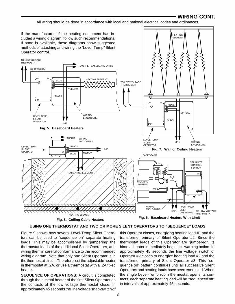
If the manufacturer of the heating equipment has in-cluded a wiring diagram, follow such recommendations.If none is available, these diagrams show suggestedmethods of attaching and wiring the “Level-Temp” SilentOperator control.
All wiring should be done in accordance with local and national electrical codes and ordinances.
Fig. 5. Baseboard Heaters
Fig. 8. Ceiling Cable Heaters
USING ONE THERMOSTAT AND TWO OR MORE SILENT OPERATORS TO “SEQUENCE” LOADS
Figure 9 shows how several Level-Temp Silent Opera-tors can be used to “sequence on” separate heatingloads. This may be accomplished by “jumpering” thethermostat leads of the additional Silent Operators, andwiring them in careful conformance to the recommendedwiring diagram. Note that only one Silent Operator is inthe thermostat circuit. Therefore, set the adjustable heaterin thermostat at .2A, or use a thermostat with a .2A fixedheater.SEQUENCE OF OPERATIONS: A circuit is completedthrough the bimetal heater of the first Silent Operator asthe contacts of the low voltage thermostat close. Inapproximately 45 seconds the line voltage snap-switch of
this Operator closes, energizing heating load #1 and thetransformer primary of Silent Operator #2. Since thethermostat leads of this Operator are “jumpered”, itsbimetal heater immediately begins its warping action. Inapproximately 45 seconds the line voltage switch ofOperator #2 closes to energize heating load #2 and thetransformer primary of Silent Operator #3. This “se-quence on” pattern continues until all successive SilentOperators and heating loads have been energized. Whenthe single Level-Temp room thermostat opens its con-tacts, each separate heating load will be “sequenced off”in intervals of approximately 45 seconds.
TO LOW VOLTAGETHERMOSTAT
BASEBOARD
TO OTHER BASEBOARD UNITS
HEATING ELEMENT
WIRINGENCLOSURE
LEVEL TEMP.SILENTOPERATOR
LINE
TO LOW VOLTAGETHERMOSTAT
HEATING ELEMENT
LEVEL TEMP.SILENTOPERATOR
WIRINGENCLOSURE
LINE
Fig. 7. Wall or Ceiling Heaters
WIRINGENCLOSURE
LINE
LEVEL TEMP.SILENTOPERATOR
Fig. 6. Baseboard Heaters With Limit
TO LOW VOLTAGETHERMOSTAT
SEPARATECONTROLSECTION
HEATINGELEMENT
LINE
THERM. WIRINGENCLOSURE
LEVEL TEMP.SILENTOPERATOR
TO HEATING ELEMENT
HEATING ELEMENT
BASEBOARD
BLUE
BLACK
YELLOW
BLUE
BLACK
YELLOW
BLUE
BLACK
YELLOW
4
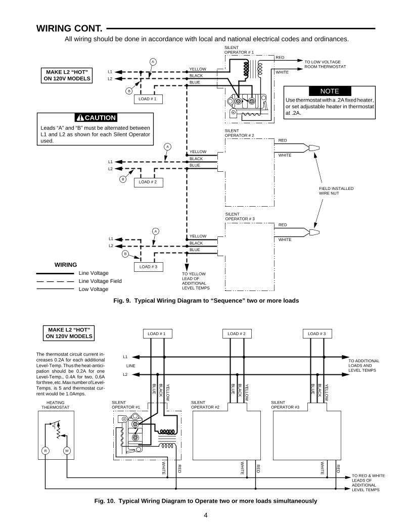
WIRING CONT.All wiring should be done in accordance with local and national electrical codes and ordinances.
MAKE L2 “HOT”ON 120V MODELS
Fig. 9. Typical Wiring Diagram to “Sequence” two or more loads
A
B
A
B
A
B
WIRINGLine Voltage
Line Voltage Field
Low Voltage
L1
L2
LOAD # 1
BLACK
BLUE
YELLOW
BLACK
BLUE
YELLOW
BLACK
BLUE
YELLOW
SILENTOPERATOR # 1
RED
WHITE
RED
WHITE
RED
WHITE
TO LOW VOLTAGEROOM THERMOSTAT
NOTEUse thermostat with a .2A fixed heater,or set adjustable heater in thermostatat .2A.
LOAD # 2
SILENTOPERATOR # 2
L1
L2
FIELD INSTALLEDWIRE NUT
LOAD # 3
SILENTOPERATOR # 3
L1
L2
TO YELLOWLEAD OFADDITIONALLEVEL TEMPS
Leads “A” and “B” must be alternated betweenL1 and L2 as shown for each Silent Operatorused.
CAUTION
WR
Fig. 10. Typical Wiring Diagram to Operate two or more loads simultaneously
The thermostat circuit current in-creases 0.2A for each additionalLevel-Temp. Thus the heat-antici-pation should be 0.2A for oneLevel-Temp., 0.4A for two, 0.6Afor three, etc. Max number of Level-Temps. is 5 and thermostat cur-rent would be 1.0Amps.
LOAD # 1 LOAD # 3LOAD # 2
L1
L2
LINE
SILENTOPERATOR #1
SILENTOPERATOR #3
SILENTOPERATOR #2
BLU
E
BLA
CK
YE
LLOW
BLU
E
BLA
CK
YE
LLOW
BLU
E
BLA
CK
YE
LLOW
TO ADDITIONALLOADS ANDLEVEL TEMPS
TO RED & WHITELEADS OFADDITIONALLEVEL TEMPS
RE
D
WH
ITE
RE
D
WH
ITE
RE
D
WH
ITE
HEATINGTHERMOSTAT
MAKE L2 “HOT”ON 120V MODELS
Imprimé aux États-Unis
PIÈCE NO 37-4701CRemplace 37-4701B
0023
WHITE-RODGERS DIVISIONEMERSON ELECTRIC CO.9797 REAVIS RD., ST. LOUIS, MO. 63123(314) 577-1300, Télécopieur (314) 577-15179999 HWY. 48, MARKHAM, ONT. L3P 3J3(905) 475-4653, Télécopieur (905) 475-4625
C.A. MOTEUR C.A. INDUCTIFNO DE TENSION ABSORBÉE / COURANT DU RÉSISTIFTYPE FRÉQUENCE THERMOSTAT NON-INDUCTIF
24A01G-3 240 V C.A., 60 Hz 0,2 A 25 A, 6000 W, 240 V 12 A, 240 V 72 A, 240 V24A01Z-10 347 V C.A., 60 Hz 0,2 A 17 A, 5900 W, 347 V24A01Z-11 600 V C.A., 60 Hz 0,2 A 12 A, 7200 W, 600 V24A05A-1 120 V C.A., 60 Hz 0,2 A 25 A, 3000 W, 120 V 16 A, 120 V 96 A, 120 V24A05E-1 208 V C.A., 60 Hz 0,2 A 25 A, 5200 W, 208 V 12 A, 208 V 72 A, 208 V24A05Z-1 277 V C.A., 60 Hz 0,2 A 22 A, 6000 W, 277 V
PLEINE CHARGE ROTOR BLOQUÉ
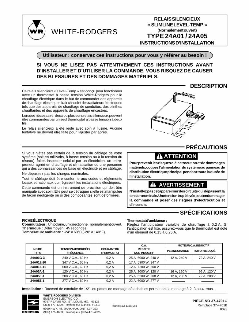
DESCRIPTIONCe relais silencieux « Level-Temp » est conçu pour fonctionneravec un thermostat à basse tension White-Rodgers pour lechauffage électrique dans le but de commander des appareilsde chauffage électriques à air chaud et des radiateurs électriquestels que des appareils de chauffage de conduites, des plintheschauffantes et des appareils de chauffage encastrés.Lorsque nécessaire, deux ou plusieurs relais silencieux peuventêtre commandés par un seul thermostat à basse tension à deuxfils.Le relais silencieux a été réglé avec soin à l’usine. Aucunetentative ne devrait être faite pour l’ajuster par après.
SPÉCIFICATIONS
PRÉCAUTIONS
ATTENTION
AVERTISSEMENT
Pour prévenir les risques d’électrocution et de dommagesmatériels, coupez l’alimentation du système au panneau dedistribution électrique principal pendant toute la durée del’installation.
N’installez pas cet appareil sur des circuits qui dépassent latension nominale. Une tension trop élevée peut endommagerla commande et poser des risques d’électrocution etd’incendie.
Si vous n’êtes pas certain de la tension du câblage de votresystème (soit en millivolts, à basse tension ou à la tension duréseau), faites inspecter celui-ci par un électricien, un entre-preneur agréé en chauffage et climatisation ou une personnequi a des connaissances de base en électricité et en câblage.Ne dépassez pas les charges nominales.Tout le câblage doit être conforme aux codes et règlementslocaux et nationaux qui régissent les installations électriques.Cette commande est un instrument de précision qui doit êtremanipulé avec soin. Elle peut se détraquer si elle est manipuléede façon négligente ou si des composantes sont déformées.
SI VOUS NE LISEZ PAS ATTENTIVEMENT CES INSTRUCTIONS AVANTD’INSTALLER ET D’UTILISER LA COMMANDE, VOUS RISQUEZ DE CAUSERDES BLESSURES ET DES DOMMAGES MATÉRIELS.
Utilisateur : conservez ces instructions pour vous y référer au besoin !
RELAIS SILENCIEUX« SLIMLINE LEVEL-TEMP »
(Normalement ouvert)
TYPE 24A01 / 24A05INSTRUCTIONS D’INSTALLATION
Thermostat d’ambiance :Réglez l’anticipateur variable de chauffage à 0,2 A. Sil’anticipation est fixe, assurez-vous que le thermostat est dotéd’un élément de 0,15 à 0,25 A.
FICHE ÉLECTRIQUECommutateur : Unipolaire, unidirectionnel, normalement ouvert.Thermique : Délai moyen : 45 secondes.Température ambiante : -24° à 60°C (-20° à 140°F).
Installation : Raccord de conduite de 1/2" ou pattes de montage détachables permettant le montage à 2, 3 ou 4 trous.
WHITE-RODGERS

2
L2
L1
ÉLÉMENTS DECHAUFFAGE
RÉSEAU
INSTALLATION
CÂBLAGETout le câblage doit être conforme aux codes et règlements locaux et nationaux qui régissent les installations électriques.
Les composantes de base du relais silencieux sont untransformateur tension de réseau à basse tension, un élémentchauffant à basse tension, un bilame compensateur à tempéra-ture ambiante et un commutateur unipolaire unidirectionnel àdéclic, normalement ouvert et à la tension du réseau.Lorsque les contacts du thermostat d’ambiance sont fermés, uncircuit est fermé qui passe par l’élément chauffant du bilame.Après environ 45 secondes, l’élément chauffant ferme lecommutateur à déclic à la tension du réseau et met ainsi soustension la charge de chauffage.Lorsque les contacts du thermostat sont ouverts, l’élémentchauffant refroidit pendant environ 45 secondes, puis lecommutateur à la tension du réseau est ouvert, ce qui met horstension la charge de chauffage.
CHARGE DECHAUFFAGE
FONCTIONNEMENTCÂBLAGE
Tension du réseauChamp à la tension du réseauBasse tension
RÉSEAU
TRANSFORMATEUR
JAUNE
NOIR
BLEU
BLANC
ROUGE
COMMUTATEUR À DÉCLICÀ LA TENSION DU RÉSEAU(NORMALEMENT OUVERT)
BILAME COMPENSATEURÀ TEMPÉRATURE AMBIANTE
ÉLÉMENT CHAUFFANTDU BILAME
Fig. 1. Câblage interne de la commande de type 24A01/05
La commande « Level-Temp » peut être installée dans n’importequelle position, sans que cela n’en affecte la performance.1. Installation à l’aide du raccord de conduite mâle de 1/2" :
Le relais peut être installé dans une boîte de raccordementstandard ou sur un panneau de câblage. Voir les exemplesd’installation dans la section CÂBLAGE. Selon la position durelais dans la boîte de raccordement, il est possible que vousayez à détacher les pattes de montage détachables.
2. Installation à l’aide des pattes de montage :a. Le relais peut être installé sur un carter en métal, une
conduite d’aération ou une plaque de montage. Lespattes de montage peuvent être détachées pour permettrel’installation à 2, 3 ou 4 trous.
b. Pour faciliter le forage des trous de montage, placez lacommande contre la surface où elle sera installée etreportez-y la position des trous. Nous vous recomman-dons d’utiliser des vis no 8 pour installer la commande.
7/16"
15/16"
1 3/8"
15/32"
9/16"
2 1/2"
2 11/16"
2 13/32" 9/16"
3 11/32"
4 1/8"
1 9/16"
1 "
3 7/16"
Fig. 2. Dimensions de la commande « Level-Temp »de type 24A01/05
PATTES DÉTACHABLES RACCORD DE CONDUITE STD DE 1/2"
Fig. 3. Schéma de câblage de la commande« LEVEL-TEMP »
ROUGE
BLEU
JAUNE
MODÈLES DE 120V :METTRE L2
SOUS TENSION
RÉSEAUCHARGETHERMOSTATÀ BASSE TENSION
BLANC
NOIR
COMMANDE « LEVEL-TEMP » DE TYPE 24A01
BOÎTIER DE CÂBLAGE THERMOSTAT
Fig.4. Appareils de chauffage électrique de conduites
3
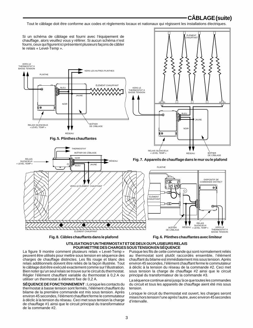
CÂBLAGE (suite)
Fig. 5. Plinthes chauffantes
PLINTHE
VERS LES AUTRES PLINTHES
ÉLÉMENT CHAUFFANT
BOÎTIERDE CÂBLAGE
Fig. 7. Appareils de chauffage dans le mur ou le plafond
VERS LE ÉLÉMENT CHAUFFANT
ÉLÉMENT CHAUFFANT
PLINTHE
Tout le câblage doit être conforme aux codes et règlements locaux et nationaux qui régissent les installations électriques.
Si un schéma de câblage est fourni avec l’équipement dechauffage, alors veuillez vous y référer. Si aucun schéma n’estfourni, ceux qui figurent ici présentent plusieurs façons de câblerle relais « Level-Temp ».
VERS LETHERMOSTAT ÀBASSE TENSION
VERS LETHERMOSTAT ÀBASSE TENSION
RELAIS SILENCIEUX« LEVEL TEMP »
ÉLÉMENTCHAUFFANT
RELAIS SILENCIEUX« LEVEL TEMP » BOÎTIER
DE CÂBLAGE
RELAISSILENCIEUX
« LEVEL TEMP »BOÎTIERDE CÂBLAGE
BOÎTIER DE CÂBLAGE
RÉSEAURELAIS
SILENCIEUX« LEVEL TEMP »
La figure 9 montre comment plusieurs relais « Level-Temp »peuvent être utilisés pour mettre sous tension en séquence descharges de chauffage distinctes. Les fils rouge et blanc desrelais additionnels doivent être reliés de la façon illustrée. Toutle câblage doit être exécuté exactement comme sur l’illustration.Bien noter qu’un seul relais se trouve sur le circuit du thermostat.Régler l’élément chauffant variable du thermostat à 0,2 A ouutiliser un thermostat à élément fixe de 0,2 A.SÉQUENCE DE FONCTIONNEMENT : Lorsque les contacts duthermostat à basse tension sont fermés, l’élément chauffant dubilame de la première commande est mis sous tension. Aprèsenviron 45 secondes, l’élément chauffant ferme le commutateurà déclic à la tension du réseau. Ceci met sous tension la chargede chauffage #1 ainsi que le circuit principal du transformateurde la commande #2.
Puisque les fils de cette commande qui sont normalement reliésau thermostat sont plutôt raccordés ensemble, l’élémentchauffant du bilame est immédiatement mis sous tension. Aprèsenviron 45 secondes, l’élément chauffant ferme le commutateurà déclic à la tension du réseau de la commande #2. Ceci metsous tension la charge de chauffage #2 ainsi que le circuitprincipal du transformateur de la commande #3.La séquence continue ainsi jusqu’à ce que toutes les commandesdu circuit et tous les appareils de chauffage aient été mis soustension.Lorsque le circuit du thermostat est ouvert, les charges serontmises hors tension l’une après l’autre, avec environ 45 secondesd’intervalle.
UTILISATION D’UN THERMOSTAT ET DE DEUX OU PLUSIEURS RELAISPOUR METTRE DES CHARGES SOUS TENSION EN SÉQUENCE
RÉSEAU
RÉSEAU
THERMOSTAT
ÉLÉMENTCHAUFFANT
RÉSEAU VERS LETHERMOSTAT ÀBASSE TENSION
Fig. 6. Plinthes chauffantes avec limiteurFig. 8. Câbles chauffants dans le plafond
DISPOSITIF DECOMMANDE DISTINCT
BLEU
JAUNE
NOIR
BLEU
JAUNE
NOIR
BLEU JAUNE
NOIR

4
CÂBLAGE (suite)
WR
Tout le câblage doit être conforme aux codes et règlements locaux et nationaux qui régissent les installations électriques.
Fig. 9. Schéma de câblage typique pour mettre deux ou plusieurs charges sous tension en séquence
A
B
A
B
A
B
CHARGE # 1
NOIR
BLEU
JAUNE
NOIR
BLEU
JAUNE
NOIR
BLEU
JAUNE
RELAISSILENCIEUX # 1
ROUGE
BLANC
ROUGE
BLANC
ROUGE
BLANC
NOTEUtiliser un thermostat avec un élémentchauffant fixe de 0,2 A ou réglerl’élément chauffant variable à 0,2 A.
CHARGE # 2
RELAISSILENCIEUX # 2
L1
L2
CHARGE # 3
RELAISSILENCIEUX # 3
L1
L2
Pour chaque relais silencieux utilisé, les fils A etB doivent alterner entre L1 et L2, comme lemontre l’illustration.
ATTENTION
MODÈLES DE 120V :METTRE L2
SOUS TENSION
L1
L2
VERS LE FIL JAUNEDU RELAIS SUIVANT
MARETTES INSTALLÉESSUR PLACE
VERS LE THERMOSTAT D’AMBIANCEÀ BASSE TENSION
L1
L2
RÉSEAU
CHARGE #1
NO
IR
JAU
NE
BLE
U
NO
IR
JAU
NE
BLE
U
NO
IR
JAU
NE
BLE
U
CHARGE #2 CHARGE #2
RELAISSILENCIEUX #1
RELAISSILENCIEUX #2
RELAISSILENCIEUX #3
Fig. 10. Schéma de câblage typique d’un circuit pilotant des charges simultanées
BLA
NC
RO
UG
E
THERMOSTATDE CHAUFFAGE
La charge sur le circuit du thermostat augmente de0,2 A pour chaque relais qui y est installé. Ainsi,l’anticipation du thermostat sera de 0,2 A avec uneseule commande « Level-Temp »; de 0,4 A avec 2commandes; de 0,6 A avec 3 commandes; etc. Lenombre maximum de commandes « Level-Temp »est de 5, représentant une charge de 1,0 A sur lethermostat.
MODÈLES DE 120V :METTRE L2
SOUS TENSION
CÂBLAGETension du réseauChamp à la tension du réseauBasse tension
VERS LES CHARGESET COMMANDES« LEVEL-TEMP »ADDITIONNELLES
BLA
NC
RO
UG
E
BLA
NC
RO
UG
E