VIDEO DE RECUL REARVIEW SYSTEM CçMARA … 4. CONNEXION DU SYSTEME FIL ROUGE Connexion au + 12V. FEU...
46
Ref : RW037-P VIDEO DE RECUL REARVIEW SYSTEM CÁMARA DE MARCHA ATRÁS MANUEL D'INSTALLATION & D'UTILISATION USER & INSTALLER MANUAL INSTALACIÓN Y USO
Transcript of VIDEO DE RECUL REARVIEW SYSTEM CçMARA … 4. CONNEXION DU SYSTEME FIL ROUGE Connexion au + 12V. FEU...
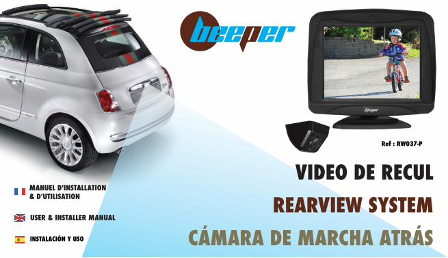
Ref : RW037-P
VIDEO DE RECULREARVIEW SYSTEM
CÁMARA DE MARCHA ATRÁS
MANUEL D'INSTALLATION& D'UTILISATION
USER & INSTALLER MANUAL
INSTALACIÓN Y USO
2
MANUEL D'UTILISATION
Introduction Nous vous remercions d'utiliser un produit BEEPER pour la sécurité et le confort de votre véhicule. Les innovations BEEPER sont conçues pour vous assurer de longues années de tranquillité, elles sont garanties durant 3 années. Notre service technique est à votre disposition pour toute information complémentaire.
Le système de vidéo de recul RW037-P est un produit électronique automobile nécessitant les compétences d'un électricien automobile pour son installation. Même si l'installation est universelle et sans complexité, nous vous conseillons de faire appel à un professionnel afin de ne pas endommager votre véhicule.
Nous souhaitons que le produit BEEPER RW037-P vous apporte entière satisfaction et améliore la sécurité de votre véhicule.
PLUS DE PRODUITS, PLUS D'INFOS
3
SOMMAIRE
)&�� 9nYfl�d�afklYddYlagf�&&&&&&&&&&&&&&&&&&&&&&&&&&&&&&&&&&&&&&&&&&&&&&&&&&&&&&&&&&&&&&&&&&&&&&&&&&&&&&&&&&&&&&&&&&&&&&&&&&&&&&&&&&&&&&&&&&&&&&&&&&&&&&&&&&&&&&&&&&&&&&&&&&&&&&&&&&&&&&&&&&&&&&&&&&&&&&&&&&&&&&&&&&&&&&&&&&&&&&&&��H&,*&�� >gf[lagfk�hjaf[ahYd]k��&&&&&&&&&&&&&&&&&&&&&&&&&&&&&&&&&&&&&&&&&&&&&&&&&&&&&&&&&&&&&&&&&&&&&&&&&&&&&&&&&&&&&&&&&&&&&&&&&&&&&&&&&&&&&&&&&&&&&&&&&&&&&&&&&&&&&&&&&&&&&&&&&&&&&&&&&&&&&&&&&&&&&&&&&&&&&&&&&&&&&&&&&&&&&&&&&&&&��H&-+&� ;gehgkalagf�\m�cal�&&&&&&&&&&&&&&&&&&&&&&&&&&&&&&&&&&&&&&&&&&&&&&&&&&&&&&&&&&&&&&&&&&&&&&&&&&&&&&&&&&&&&&&&&&&&&&&&&&&&&&&&&&&&&&&&&&&&&&&&&&&&&&&&&&&&&&&&&&&&&&&&&&&&&&&&&&&&&&&&&&&&&&&&&&&&&&&&&&&&&&&&&&&&&&&&&&&&&&&&��H&-,&�� ;gff]pagf�\m�kqkl®e]�&&&&&&&&&&&&&&&&&&&&&&&&&&&&&&&&&&&&&&&&&&&&&&&&&&&&&&&&&&&&&&&&&&&&&&&&&&&&&&&&&&&&&&&&&&&&&&&&&&&&&&&&&&&&&&&&&&&&&&&&&&&&&&&&&&&&&&&&&&&&&&&&&&&&&&&&&&&&&&&&&&&&&&&&&&&&&&&&&&&&&&&&&&&&&&&&&&��H&.-&�� AfklYddYlagf�\]�d�[jYf�&&&&&&&&&&&&&&&&&&&&&&&&&&&&&&&&&&&&&&&&&&&&&&&&&&&&&&&&&&&&&&&&&&&&&&&&&&&&&&&&&&&&&&&&&&&&&&&&&&&&&&&&&&&&&&&&&&&&&&&&&&&&&&&&&&&&&&&&&&&&&&&&&&&&&&&&&&&&&&&&&&&&&&&&&&&&&&&&&&&&&&&&&&&&&&&&&&&��H&1.&�� AfklYddYlagf�\]�dY�[YejY�&&&&&&&&&&&&&&&&&&&&&&&&&&&&&&&&&&&&&&&&&&&&&&&&&&&&&&&&&&&&&&&&&&&&&&&&&&&&&&&&&&&&&&&&&&&&&&&&&&&&&&&&&&&&&&&&&&&&&&&&&&&&&&&&&&&&&&&&&&&&&&&&&&&&&&&&&&&&&&&&&&&&&&&&&&&&&&&&&&&&&&&&&&&&&��H&)(/&�� MladakYlagf�\m�kqkl®e]�&&&&&&&&&&&&&&&&&&&&&&&&&&&&&&&&&&&&&&&&&&&&&&&&&&&&&&&&&&&&&&&&&&&&&&&&&&&&&&&&&&&&&&&&&&&&&&&&&&&&&&&&&&&&&&&&&&&&&&&&&&&&&&&&&&&&&&&&&&&&&&&&&&&&&&&&&&&&&&&&&&&&&&&&&&&&&&&&&&&&&&&&&&&&&&&&&&��H&)+0&�� <gff]k�l][`faim]�&&&&&&&&&&&&&&&&&&&&&&&&&&&&&&&&&&&&&&&&&&&&&&&&&&&&&&&&&&&&&&&&&&&&&&&&&&&&&&&&&&&&&&&&&&&&&&&&&&&&&&&&&&&&&&&&&&&&&&&&&&&&&&&&&&&&&&&&&&&&&&&&&&&&&&&&&&&&&&&&&&&&&&&&&&&&&&&&&&&&&&&&&&&&&�&&&&&&&&&�H&),1&�� ;]jla^a[Ylagfk�&&&&&&&&&&&&&&&&&&&&&&&&&&&&&&&&&&&&&&&&&&&&&&&&&&&&&&&&&&&&&&&&&&&&&&&&&&&&&&&&&&&&&&&&&&&&&&&&&&&&&&&&&&&&&&&&&&&&&&&&&&&&&&&&&&&&&&&&&&&&&&&&&&&&&&&&&&&&&&&&&&&&&&&&&&&&&&&&&&&&&&&&&&&&&&&&&&&&&&&&&&&&&&&&&�H&)-
Continuez la découverte sur www.beeper.fr
MAC PH
Texte
4
1. AVANT L'INSTALLATION
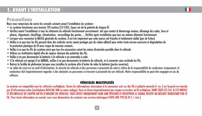
PrécautionsFgmk�ngmk�j]e]j[agfk�\]�kmanj]�d]k�[gfk]adk�kmanYflk�YnYfl�d�afklYddYlagf�\m�kqkl®e]�2��D]�kqkl®e]�^gf[lagff]�kgmk�l]fkagf�)*N�[gflafm� )*�N�<;!&�Kgq]r�k½j�\]�dY�hgdYjal�\]�[`Yim]�^ad&��Nja^a]r�YnYfl�d�afklYddYlagf�ka�lgmk�d]k�de]flk�\m�n`a[md]�^gf[lagff]fl�[gjj][l]e]fl��l]dk�im]�[gflY[l���\eYjjY_]�egl]mj$�YddmeY_]�\]k�[g\]k$�^]mp�]l�� �h`Yj]k$�[da_fglYflk$�[`Ym^^Y_]$�[daeYlakYlagf$��n]jjgmaddY_]�\]k�hgjl]k$�&&&�Nja^a]r�Yhj®k�afklYddYlagf�im]�lgmk�[]k�e¯e]k�de]flk�^gf[lagff]fl&��Dgjkim]�ngmk�[gff][l]r�dY�E9KK=�_fjYd]�\m�kqkl®e]$�ad�]kl�lj®k�aehgjlYfl�im]�[]ll]�eYkk]�kgal�^jYf[`]�]l�lglYd]e]fl�klYZd]� hYk�\]�^mal]k!&���N]add]r�§�[]�im]�lgmk�d]k�^adk�hYkkYfl�\Yfk�\]k�]f\jgalk�k]jjk�kga]fl�hjgl_k�hYj�\m�jmZYf�Y\`ka^�hgmj�nal]j�lgml]�lgjkagf�]p[]kkan]�]l�\_jY\Ylagf�\]� �dY�hjgl][lagf�hdYklaim]�\m�^ad�Yn][�jakim]�\]�eYmnYak�[gflY[lk&��N]add]r�§�[]�im]�d]k�^adk�\m�kqkl®e]�Yafka�im]�lgmk�d]k�Y[[]kkgaj]k�kga]fl�d]k�ea]mp�\akkaemdk�hgkkaZd]�\Yfk�d]�n`a[md]��Mladak]r�mf�emdlae®lj]�\a_alYd�Y^af�\]�j]hj]j�[`Y[mf]�\]k�hgdYjalk�\]k�^adk&��N]add]r�§�f]�hYk�\[gff][l]j�dY�ZYll]ja]�ka�d]�n`a[md]�Y�mf�YmlgjY\ag�§�[g\]&��Ka�d]�n`a[md]�]kl�imah�\�mf�9AJ:9?$�n]add]r�§�f]�hYk�\[gff][l]j�dY�ZYll]ja]�\m�n`a[md]$�fa�§�[gff][l]j�kYfk�[]jlalm\]�d]k�^adk&��J]laj]r�d]�^mkaZd]�\]�hdY^gffa]j�dgjkim]�ngmk�afklYdd]r�d]�kqkl®e]�Y^af�\�nal]j�\]�na\]j�dY�ZYll]ja]� hgjl]k�gmn]jl]k!&��DY�na\g�\]�j][md�]kl�mf�gmlad�\�af^gjeYlagf$�dY�k[mjal�\m�n`a[md]�]l�\]k�h]jkgff]k�§�hjgpaeal�\]�[]dma%[a�j]d®n]�\]�dY�j]khgfkYZadal�\m�[gf\m[l]mj�mfaim]e]fl$�d]����[gf\m[l]mj�\gal�aehjYlan]e]fl�j]_Yj\]j�ka�\]k�gZklY[d]k�gm�h]jkgff]k�k]�ljgmn]fl�§�hjgpaeal�\]�kgf�n`a[md]&�Fglj]�j]khgfkYZadal�f]�h]ml�¯lj]�]f_Y_]�]f�[Yk�\]����[gddakagf&
VÉHICULES MULTIPLEXÉSD]�kqkl®e]�]kl�[gehYlaZd]�Yn][�d]k�n`a[md]k�emdlahd]pk&�Lgml]k�d]k�af^gjeYlagfk�f[]kkYaj]k�§�dY�[gff]pagf�kgfl�kmj�\]k�^adk�§�hgdYjal�fgjeYd]� #�gm�%!�kmj�d]kim]dk�f]�ljYfkal]�hYk�\�af^gjeYlagf�[g\]� emdlahd]p]�:MK;9F$�N9F�gm�Ymlj]�[g\Y_]!&�Ngmk�f]�\]n]r�aehjYlan]e]fl�hYk�[gmh]j�gm�lgm[`]j�mf�^ad�emdlahd]p&�<9FK�LGMK�D=K�;9K$�AD�=KL�AFMLAD=�=L�< ;GFK=ADD �<=�;GMH=J�MF�>AD�<�GJA?AF=�<M�N @A;MD=&�NGMK�<=N=R�MFAIM=E=FL�>9AJ=�MF=� HAKKMJ=�=L�J ;MH J=J�D=�KA?F9D�HGKALA>�GM�F ?9LA>�LJ9FKAL9FL�H9J�;=�>AD&�Hgmj�lgml]�af^gjeYlagf�gm�[gfk]ad$�fgmk�ngmk�\]eYf\gfk�\]�[gflY[l]j�fgk�k]jna[]k�l][`faim]k�(�01*�.1(�/1*� (&+,�Ē�'�eaf&!

5
2. FONCTIONS PRINCIPALES
• Le RW037-p est un kit de vidéo de recul pour véhicules de petit et moyen gabarit (autos, monospaces, breaks, 4x4, ...)• Au passage en marche arrière, le système de vidéo de recul se met en fonction automatiquement.�wD�[jYf�h]je]l�\]�nakmYdak]j�d�Yf_d]�egjl�Yjja®j]�hgmj�]^^][lm]j�nglj]�eYfg]mnj]�]f�eYj[`]�Yjja®j]�]f�lgml]�k[mjal&�w<®k�d�Yjjêt de la marche arrière, le système est inactif.��<]k�da_f]k�\]�_YZYjal�\]�\a^^j]fl]k�[gmd]mjk�h]je]ll]fl�\]�nakmYdak]j�d]k�\aklYf[]k�dgjk�\�mf]�eYfg]mnj]� ^gf[lagf�YffmdYZd]!
3. COMPOSITION DU KIT
CBA ECRAN MONITEUR FAISCEAU CAMERA
6
4. CONNEXION DU SYSTEME
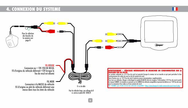
FIL ROUGE
Connexion au + 12V. FEU DE RECUL
Fil d'origine du véhicule délivrant +12V lorsque le
feu de recul est allumé
FIL NOIR
Connexion à la MASSE du véhicule
Fil d'origine ou plot du véhicule délivrant une
masse dans tous les états du véhicule
CAM 2
DC12V
CAM 1
8 m. de câble
Pour les véhicules longs, une rallonge de 8 m. existe en option Réf : RX40/8
9N=JLAKK=E=FL��wN @A;MD=K�AFL=J<AK9FLK�<=�:J9F;@=J�MF�;GFKGEE9L=MJ�KMJ�D=�>9AK;=9M�>=M�<=�J=;MDSur certains véhicules le +12 V Feu de recul est parasité lorsque le moteur est en marche ce qui peut perturber le bon
fonctionnement du radar de recul ou du kit caméra de recul.
Dans d'autres cas, ce +12 V Feu de recul n'autorise aucun consommateur supplémentaire.
Pour tous ces véhicules, Beeper a développé le module RCAN R2 afin de récupérer l'information +12 V Feu de recul à partir
du réseau CANBUS. Ce module se connecte sur le CANBUS du véhicule compatible et permet de délivrer un +12V Feu de recul
pour la connexion d'un radar ou d'une caméra de recul
Réf : RCANR2, plus d'infos & liste des véhicules compatibles : http://www.beeper.fr/radar-camera-de-recul/rcanr2.php
Pour la séléction
des boucles de
la caméra voir
page 8

DC
12
V
CA
M 1
7
4. CONNEXION DU SYSTEME (si ajout d'une caméra supplémentaire)
8 m. de câblePour les véhicules longs,
une rallonge
de 8 m. existe en option
Réf : RX40/8
Vidéo Alimentation
FIL ROUGEConnexion au + 12V. FEU DE RECUL
Fil d'origine du véhicule délivrant +12V lorsque le feu de
recul est allumé
FIL NOIRConnexion à la MASSE du véhicule
Fil d'origine ou plot du véhicule délivrant une masse dans
tous les états du véhicule
Ne pas connecter & à ISOLERVeuillez protéger ce connecteur afin
qu'il ne soit pas mis en contact avec
une partie métallique du véhicule
Ecran
Vidéo
Alimentation
Caméra avant
CAM2
Boucle :
��:dYf[`]� )!�2�eajgaj�[YejY��:d]m� *!�2�_YZYjalk
Connexion au + 12V. APRES CONTACT
Fil d'origine du véhicule délivrant +12V
lorsque le contact du véhicule est mis
FIL NOIRMASSE
Afl]jjmhl]mj� *!�\]�[geeYf\]�de la caméra avant et de l'écran
Caméra arrièreCAM1
9N=JLAKK=E=FL��wN @A;MD=K�AFL=J<AK9FLK�<=�:J9F;@=J�UN CONSOMMATEUR SUR LE FAISCEAU FEU DE RECUL
Sur certains véhicules le +12 V Feu de recul est parasité lorsque le moteur est en
marche ce qui peut perturber le bon fonctionnement du radar de recul ou du kit
caméra de recul.
Dans d'autres cas, ce +12 V Feu de recul n'autorise aucun consommateur
supplémentaire.
Pour tous ces véhicules, Beeper a développé le module RCAN R2 afin de
récupérer l'information +12 V Feu de recul à partir du réseau CANBUS. Ce
module se connecte sur le CANBUS du véhicule compatible et permet de délivrer
un +12V Feu de recul pour la connexion d'un radar ou d'une caméra de recul
Réf : RCANR2, plus d'infos & liste des véhicules compatibles :
http://www.beeper.fr/radar-camera-de-recul/rcanr2.php
Pour la séléction
des boucles de
la caméra voir
page 8
CA
M 2
Vidéo
FIL ROUGE
Vidéo Alimentation
Ne pas connecter & à ISOLERVeuillez protéger ce connecteur afin
qu'il ne soit pas mis en contact avec
une partie métallique du véhicule
FIL NOIR
FIL ROUGE

6. INSTALLATION DE LA CAMERA
:gm[d]�N=JL=�5�AFN=JKAGF�@9ML�'�:9K�w\]�d�aeY_]�kmj�d�[jYf Boucle VERTE Fermée = IMAGE normale Boucle VERTE Ouverte (coupée) = IMAGE inversée haut / bas ��Kd][lagf�\�gja_af]
:gm[d]�:D9F;@=�5�?9:9JALK�\]�nakmYdakYlagf�\]k�\aklYf[]k :gm[d]�:D9F;@=w>]je]�5�?YZYjalk�NAKA:D=K ��Kd][lagf�\�gja_af]� :gm[d]�:D9F;@=wGmn]jl]� [gmh]!�5�?YZYjalk�FGF�NAKA:D=K
8
OPTIONS CAMÉRA : GABARIT & INVERSION IMAGE
SÉLECTION DES BOUCLES DE LA CAMÉRA
La sélection de ces options se fait avec la caméranon alimentée.
DY�kd][lagf�\�gja_af]�]kl�^Yal]�hgmj�mf]�[YejY�hgkalagff]��`gjargflYd]e]fl�$�mf�[jYf�^ap�gm�[gdd�hYj�d]�\]kkmk���]f�n]jkagf�[YejY�\]�j][md� _YZYjalk�nakaZd]k!�&Hgmj�[`Yf_]j�d�lYl�\�mf]�\]k�*�Zgm[d]k$�n]madd]r�Ym�hjYdYZd]�\[gff][l]j�dY�[YejY�hmak�dY�j][gff][l]j�Yhj®k�ghjYlagf&
9
95 mm
76 mm88 mm
60 mm
24 mm
89 mm
5. INSTALLATION DE L'ECRAN
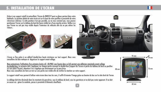
Grâce à son support rotatif et autocollant, l'écran du RW037-P peut se placer partout dans votre habitacle. La position idéale de votre écran est sur le haut de votre pavillon à proximité de votre rétroviseur intérieur. Si cette position n'est pas possible, ou ne vous convient pas, vous pouvez positionner l'écran sur le tableau de bord de façon visible lors d'une marche arrière. Veillez à ce que l'écran ne soit pas trop visible depuis l'exterieur du véhicule afin de ne pas attirer les voleurs.
L'écran se fixe grâce à un adhésif double-face haute résistance sur tout support. Nous vous conseillons de bien nettoyer et dégraisser le support avant collage.
Nous préconisons l'utilisation d'un primaire (notre réf : RX-PR01 non founie dans ce kit) permet une adhésion maximale avant collage du double-face. Le primaire doit s'appliquer sur chaque partie recevant le double-face (support de l'écran et partie du tableau de bord ou pavillon où sera placé l'écran). Attention il ne s'applique pas directement sur le pare brise.Nous vous conseillons de faire un test sur une partie non visible afin de vérifier la réaction sur votre support.
Le support rotatif vous permet d'utiliser votre écran dans tous les sens, il suffit d'orienter l'image grâce au bouton du bas sur le côté droit de l'écran.
Le câblage doit être dissimulé dans les montants de pare-brise, sous le tableau de bord, sous les garnitures et ne doit pas rester apparent. Il ne doit en aucun cas : gêner la conduite, passer à proximité d'éléments chauffants.
10
6. INSTALLATION DE LA CAMERA
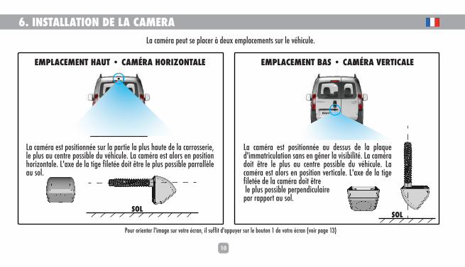
EMPLACEMENT HAUT • CAMÉRA HORIZONTALE
La caméra est positionnée sur la partie la plus haute de la carrosserie, le plus au centre possible du véhicule. La caméra est alors en position horizontale. L'axe de la tige filetée doit être le plus possible parrallèle au sol.
EMPLACEMENT BAS • CAMÉRA VERTICALE
La caméra est positionnée au dessus de la plaque d'immatriculation sans en gêner la visibilité. La caméra doit être le plus au centre possible du véhicule. La caméra est alors en position verticale. L'axe de la tige filetée de la caméra doit être le plus possible perpendiculairepar rapport au sol.
SOLSOL
La caméra peut se placer à deux emplacements sur le véhicule.
Pour orienter l'image sur votre écran, il suffit d'appuyer sur le bouton 1 de votre écran (voir page 13)

11
6. INSTALLATION DE LA CAMERALa caméra est positionnée au dessus de la plaque d'immatriculation sans en gêner la visibilité, et doit être placée le plus au centre possible du véhicule.
Retirez la veilleuse de plaque d'origine de son logement pour pouvoir repérer l'emplacement le plus adéquat à droite, à gauche ou directement sur le support de la veilleuse de plaque. Dans le coffre du véhicule, repérez comment ressortir le fil de la caméra, permettre la fixation de la caméra et pouvoir la connecter sur les fils d'origine du véhicule comme indiqué pages précédentes.
Après avoir choisi le meilleur emplacement de la caméra, percez un trou d'un diamètre de 6 mm.Nous vous conseillons de protéger le support d'un adhésif (type adhésif de peintre) afin de pas endommager lors du perçage. Un ponçage léger peut-être nécessaire après le perçage du trou pour ébavurer le contour du trou et afin de ne pas endommager l'isolant du câble de la caméra.
Retirez l'écrou de la tige filetée de la caméra, passez le fil de la caméra (micro-connecteur) par ce trou. Récupérez ce fil dans le coffre, insérez l'écrou et vissez-le sur la tige filetée. Le serrage doit être suffisamment fort afin d'assurer l'étanchéité et la bonne tenue de la caméra, attention toute fois à ne pas serrer trop fort ce qui pourrait casser la tige filtée de la caméra.
1
2
3
SOL
EMPLACEMENT BASCAMERA VERTICALE

12
6. INSTALLATION DE LA CAMERALa caméra est positionnée sur la partie la plus haute de la carrosserie, le plus au centre possible du véhicule.
Retirez la garniture de votre coffre afin de repérez comment ressortir le fil de la caméra et permettre la fixation de celle-ci. Pour la connexion sur les fils d'origine du véhicule, veuillez vous reporter aux pages précédentes.
Après avoir choisi le meilleur emplacement de la caméra, percez un trou d'un diamètre de 8 mm.Nous vous conseillons de protéger le support d'un adhésif (type adhésif de peintre) afin de pas endommager lors du perçage. Un ponçage léger peut-être nécessaire après le perçage du trou pour ébavurer le contour du trou et afin de ne pas endommager l'isolant du câble de la caméra.
Retirez l'écroun de la tige filetée de la caméra, passez le fil de la caméra (micro-connecteur) par ce trou. Récupérez ce fil dans le coffre, insérez l'écrou et vissez-le sur la tige filetée. Le serrage doit être suffisamment fort afin d'assurer l'étanchéité et la bonne tenue de la caméra, attention toute fois à ne pas serrer trop fort ce qui pourrait casser la tige filtée de la caméra.
1
2
3
SOL
EMPLACEMENT HAUTCAMERA HORIZONTALE
13
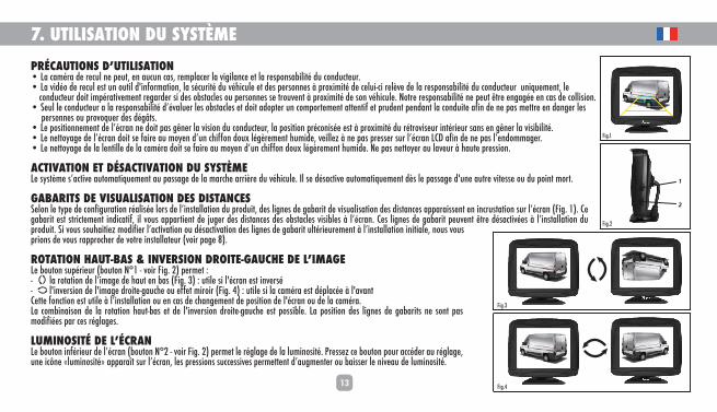
7. UTILISATION DU SYSTÈMEHJ ;9MLAGFK�<�MLADAK9LAGF���DY�[YejY�\]�j][md�f]�h]ml$�]f�Ym[mf�[Yk$�j]ehdY[]j�dY�na_adYf[]�]l�dY�j]khgfkYZadal�\m�[gf\m[l]mj&��DY�na\g�\]�j][md�]kl�mf�gmlad�\�af^gjeYlagf$�dY�k[mjal�\m�n`a[md]�]l�\]k�h]jkgff]k�§�hjgpaeal�\]�[]dma%[a�j]d®n]�\]�dY�j]khgfkYZadal�\m�[gf\m[l]mj��mfaim]e]fl$�d]�����[gf\m[l]mj�\gal�aehjYlan]e]fl�j]_Yj\]j�ka�\]k�gZklY[d]k�gm�h]jkgff]k�k]�ljgmn]fl�§�hjgpaeal�\]�kgf�n`a[md]&�Fglj]�j]khgfkYZadal�f]�h]ml�¯lj]�]f_Y_]�]f�[Yk�\]�[gddakagf&��K]md�d]�[gf\m[l]mj�Y�dY�j]khgfkYZadal�\�nYdm]j�d]k�gZklY[d]k�]l�\gal�Y\ghl]j�mf�[gehgjl]e]fl�Yll]fla^�]l�hjm\]fl�h]f\Yfl�dY�[gf\mal]�Y^af�\]�f]�hYk�e]llj]�]f�\Yf_]j�d]k������h]jkgff]k�gm�hjgngim]j�\]k�\_¨lk&��D]�hgkalagff]e]fl�\]�d�[jYf�f]�\gal�hYk�_¯f]j�dY�nakagf�\m�[gf\m[l]mj$�dY�hgkalagf�hj[gfak]�]kl�§�hjgpaeal�\m�jljgnak]mj�aflja]mj�kYfk�]f�_¯f]j�dY�nakaZadal&��D]�f]llgqY_]�\]�d�[jYf�\gal�k]�^Yaj]�Ym�egq]f�\�mf�[`a^^gf�\gmp�d_®j]e]fl�`mea\]$�n]add]r�§�f]�hYk�hj]kk]j�kmj�d�[jYf�D;<�Y^af�\]�f]�hYk�d�]f\geeY_]j&��D]�f]llgqY_]�\]�dY�d]fladd]�\]�dY�[YejY�\gal�k]�^Yaj]�Ym�egq]f�\�mf�[`a^^gf�\gmp�d_®j]e]fl�`mea\]&�F]�hYk�f]llgq]j�Ym�dYn]mj�§�`Yml]�hj]kkagf&
ACTIVATION ET DÉSACTIVATION DU SYSTÈMED]�kqkl®e]�k�Y[lan]�YmlgeYlaim]e]fl�Ym�hYkkY_]�\]�dY�eYj[`]�Yjja®j]�\m�n`a[md]&�Ad�k]�\kY[lan]�YmlgeYlaim]e]fl�\®k�d]�hYkkY_]�\�mf]�Ymlj]�nal]kk]�gm�\m�hgafl�egjl&
GABARITS DE VISUALISATION DES DISTANCESK]dgf�d]�lqh]�\]�[gf^a_mjYlagf�jYdak]�dgjk�\]�d�afklYddYlagf�\m�hjg\mal$�\]k�da_f]k�\]�_YZYjal�\]�nakmYdakYlagf�\]k�\aklYf[]k�YhhYjYakk]fl�]f�af[jmklYlagf�kmj�d�[jYf� >a_&�)!&�;]�_YZYjal�]kl�klja[l]e]fl�af\a[Yla^$�ad�ngmk�YhhYjla]fl�\]�bm_]j�\]k�\aklYf[]k�\]k�gZklY[d]k�nakaZd]k�§�d�[jYf&�;]k�da_f]k�\]�_YZYjal�h]mn]fl�¯lj]�\kY[lan]k�§�d�afklYddYlagf�\m�hjg\mal&�Ka�ngmk�kgm`Yala]r�eg\a^a]j�d�Y[lanYlagf�gm�\kY[lanYlagf�\]k�da_f]k�\]�_YZYjal�mdlja]mj]e]fl�§�d�afklYddYlagf�afalaYd]$�fgmk�ngmkhjagfk�\]�ngmk�jYhhjg[`]j�\]�nglj]�afklYddYl]mj� ngaj�hY_]�0!&
JGL9LAGF�@9ML%:9K���AFN=JKAGF�<JGAL=%?9M;@=�<=�D�AE9?=D]�Zgmlgf�kmhja]mj� Zgmlgf�F�)�%�ngaj�>a_&�*!�h]je]l�2%��������dY�jglYlagf�\]�d�aeY_]�\]�`Yml�]f�ZYk� >a_&�+!�2�mlad]�ka�d�[jYf�]kl�afn]jk�%��������d�afn]jkagf�\]�d�aeY_]�\jgal]%_Ym[`]�gm�]^^]l�eajgaj� >a_&�,!�2�mlad]�ka�dY�[YejY�]kl�\hdY[]�§�d�YnYfl;]ll]�^gf[lagf�]kl�mlad]�§�d�afklYddYlagf�gm�]f�[Yk�\]�[`Yf_]e]fl�\]�hgkalagf�\]�d�[jYf�gm�\]�dY�[YejY&DY� [geZafYakgf�\]� dY� jglYlagf�`Yml%ZYk�]l� \]� d�afn]jkagf�\jgal]%_Ym[`]�]kl� hgkkaZd]&� DY�hgkalagf�\]k� da_f]k�\]�_YZYjalk�f]� kgfl� hYk�eg\a^a]k�hYj�[]k�j_dY_]k&
DMEAFGKAL �<=�D� ;J9FD]�Zgmlgf�af^ja]mj�\]�d�[jYf� Zgmlgf�F�*�%�ngaj�>a_&�*!�h]je]l�d]�j_dY_]�\]�dY�dmeafgkal&�Hj]kk]r�[]�Zgmlgf�hgmj�Y[[\]j�Ym�j_dY_]$�mf]�a[¸f]��dmeafgkal��YhhYjY³l�kmj�d�[jYf$�d]k�hj]kkagfk�km[[]kkan]k�h]je]ll]fl�\�Ym_e]fl]j�gm�ZYakk]j�d]�fan]Ym�\]�dmeafgkal&
1
2
>a_&*
>a_&)
>a_&+
>a_&,
14
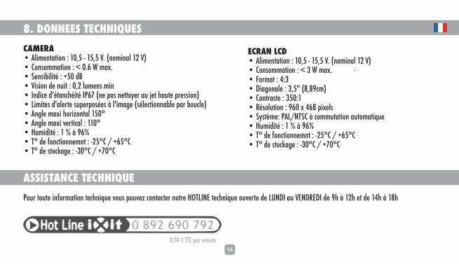
8. DONNEES TECHNIQUESCAMERA��9dae]flYlagf�2�)($-�%�)-$-�N&� fgeafYd�)*�N!���;gfkgeeYlagf�2�4�(&.�O�eYp&��K]fkaZadal�2�#-(�\:��Nakagf�\]�fmal�2�($*�dme]fk�eaf��Af\a[]�\�lYf[`al�AH./� f]�hYk�f]llgq]j�Ym�b]l�`Yml]�hj]kkagf!��Daeal]k�\�Yd]jl]�kmh]jhgk]k�§�d�aeY_]� kd][lagffYZd]�hYj�Zgm[d]!��9f_d]�eYpa�`gjargflYd�)-(���9f_d]�eYpa�n]jla[Yd�2�))(���@mea\al�2�)���§�1.���L��\]�^gf[lagff]efl�2�%*-�;�'�#.-�;��L��\]�klg[cY_]�2�%+(�;�'�#/(�;
ASSISTANCE TECHNIQUE Hgmj�lgml]�af^gjeYlagf�l][`faim]�ngmk�hgmn]r�[gflY[l]j�fglj]�@GLDAF=�l][`faim]�gmn]jl]�\]�DMF<A�Ym�N=F<J=<A�\]�1`�§�)*`�]l�\]�),`�§�)0`
ECRAN LCD��9dae]flYlagf�2�)($-�%�)-$-�N&� fgeafYd�)*�N!���;gfkgeeYlagf�2�4�+�O�eYp&��>gjeYl�2�,2+��<aY_gfYd]�2�+$-�� 0$01[e!��;gfljYkl]�2�+-(2)��Jkgdmlagf�2�1.(�p�,.0�hap]dk���Kqkl®e]2�H9D'FLK;�§�[geemlYlagf�YmlgeYlaim]��@mea\al�2�)���§�1.���L��\]�^gf[lagff]efl�2�%*-�;�'�#.-�;��L��\]�klg[cY_]�2�%+(�;�'�#/(�;
(&+,�Ē�LL;�hYj�eafml]

15
9. DECLARATION DE CONFORMITENous IXIT
� **0�Jm]�\]�d�9f[a]ff]�<akladd]ja]�� .1,((�?D=AR �>jYf[]�
<[dYjgfk�kgmk�fglj]�hjghj]�j]khgfkYZadal�im]�d]�hjg\malRW037-P Lqh]�2�Caméra de recul9mim]d�[]ll]�\[dYjYlagf�k�Yhhdaim]$�kgfl�[gf^gje]k�Ymp�fgje]k�Yhhda[YZd]k���\g[me]flk�fgjeYla^k�kmanYflk�2�=eYjc�*((1')1�=;�kgmk�d]�F��\�`gegdg_Ylagf�]*,(+)0,0JG@K�k]dgf�dY�\aj][lan]�*((*'1-';=J=9;@
;gf^gjee]fl�Ymp�\akhgkalagfk�\m�*)'(1'*((/$?d]ar$�d]�*-�bmadd]l�*()+���������������������������������������������������������
L`a]jjq�:addYm��<aj][l]mj�_fjYd�
GARANTIE ANS3
e24 031848
RoHS

17
USER MANUAL
Introduction Thank you for using a product BEEPER for safety and comfort of your vehicle. BEEPER innovations are designed to ensure many years of tranquility, they are guaranteed for 3 years. Our technical department is at your disposal for further information.
The rearview system BEEPER RW037-P is an automotive electronic product requiring the skills of an automotiv electrician to install it. Even if he installation is universal and without complexity, we recommend that you hire a professional to prevent damage to your vehicle..
We want the product BEEPER RW037-P will meet your requirements and improves the security of your vehicles.
PLUS DE PRODUITS, PLUS D'INFOS

18
SUMMARY
1. Before installation ........................................................................................................................................................................................................ P.19
2. Main functions ............................................................................................................................................................................................................ P.20
3. Kit composition ............................................................................................................................................................................................................ P.20
4. System connection ....................................................................................................................................................................................................... P.21
5. Monitor installation ..................................................................................................................................................................................................... P.24
6. Camera installation ..................................................................................................................................................................................................... P.25
7. System utilisation ........................................................................................................................................................................................................ P.28
8. Technical data ............................................................................................................................................................................................................ . P.29
9. Declaration of conformity ............................................................................................................................................................................................. P.30
Keep on discovering onwww.beeper.fr

19
1. BEFORE INSTALLATION
WarningThank you observe the following before installing the system:
��L`]�kqkl]e�jmfk�gf�)*N�<;� )*�N�<;!&�:]�kmj]�l`]�hgdYjalq�g^�]Y[`�oaj]&��;`][c�Z]^gj]�afklYddYlagf�a^�Ydd�]d]e]flk�g^�l`]�[Yj�Yj]�ogjcaf_�hjgh]jdq�km[`�Yk�a_falagf���eglgj�klYjlaf_$�da_`laf_k�Yf\�`]Y\da_`lk$�lmjf�ka_fYd$�`]Ylaf_$�Yaj�[gf\alagfaf_$�hgo]j�\ggj�dg[ck$�&&&�;`][c�Y^l]j�afklYddYlaf_�Ydd�l`]k]�]d]e]flk�ogjc&��O`]f�qgm�[gff][l�l`]�kqkl]e�k�_jgmf\$�al�ak�n]jq�aehgjlYfl�l`Yl�l`ak�_jgmf\�[gff][lagf�ak�[gehd]l]dq�gh]f�Yf\�klYZd]� fg�d]Yck!&��=fkmj]�l`Yl�]n]jq�oaj]�hYkkaf_�af�la_`l�khY[]k�Yj]�hjgl][l]\�Zq�Y\`]kan]�lYh]�lg�Ynga\�]p[]kkan]�loaklaf_�Yf\�\]_jY\Ylagf�l`]�hdYkla[�oaj]�oal`�Y�jakc�g^�ZY\�[gflY[lk&��=fkmj]�l`Yl�oaj]�g^�l`]�kqkl]e�Yf\�Ydd�l`]�kY^]lq�Y[[]kkgja]k�Yj]�Z]kl�`a\\]f�af�l`]�n]`a[d]�Yk�hgkkaZd]$�f]n]j�^gj_]l�qgm�afklYddaf_�Y�k][mjalq�kqkl]e&��Mk]�Y�\a_alYd�emdlae]l]j�lg�a\]fla^q�l`]�hgdYjalq�g^�]Y[`�kgf&��<g�fgl�\ak[gff][l�l`]�ZYll]jq�a^�l`]�n]`a[d]�`Yk�Y�jY\ag�[g\]&��A^�l`]�n]`a[d]�ak�]imahh]\�oal`�Yf�9AJ:9?$�\g�fgl�\ak[gff][l�l`]�n]`a[d]�ZYll]jq&��J]egn]�l`]�^mk]�^jge�[]adaf_�o`]f�afklYddaf_�l`]�kqkl]e�lg�hj]n]fl�ZYll]jq�\jYaf� gh]f!&��L`]�j]n]jkaf_�na\]g�ak�Yf�af^gjeYlagf�lggd$�n]`a[d]�kY^]lq�Yf\�l`gk]�[dgk]�lg�al�ak�l`]�j]khgfkaZadalq�g^�l`]�\jan]j�gfdq$�\jan]j�emkl�YdoYqk�[`][c�a^�gZklY[d]k�gj�h]ghd]�af�l`]�na[afalq�g^�l`]�n]`a[d]&�Gmj�j]khgfkaZadalq�[Yf�fgl�Z]�]f_Y_]\�af�[Yk]�gf�[gddakagf&
CANBUS VEHICLESL`]�kqkl]e�ak�[gehYlaZd]�oal`�[YfZmk�n]`a[d]k&�9dd�l`]�af^gjeYlagf�f]]\]\�lg�[gff][l�oaj]�Yj]�gf�fgjeYd�hgdYjalq� #�gj�%!�g^�o`a[`�\g]k�fgl�hYkk�[g\]\�af^gjeYlagf� ;9F:MK$�N9F�gj�gl`]j�[g\af_!&�Qgm�k`gmd\�YZkgdml]dq�fgl�[ml�gj�lgm[`�Y�[YfZmk�oaj]&�AF�9DD�;9K=K$�AL�AK�MK=D=KK�9F<�J=;GEE=F<=<�;MLLAF?�OAJ=�GJA?AF9D�N=@A;D=&�QGM�EMKL�GFDQ�E9C=�9�KHDA;=�9F<�J=;GN=J�L@=�HGKALAN=�GJ�F=?9LAN=�KA?F9D�@9F<D=<�:Q�L@AK�L@J=9<&�>gj�^mjl`]j�af^gjeYlagf�gj�Y\na[]$�o]�mj_]�qgm�lg�[gflY[l�gmj�l][`fa[Yd�\]hYjle]fl�(�01*�.1(�/1*� Ē�(&+,�'�eaf&!
20
2. MAIN FUNCTIONS
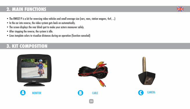
• The RW037-P is a kit for reversing video vehicles and small average size (cars, vans, station wagons, 4x4, ...)• In the car into reverse, the video system gets back on automatically.• The screen displays the rear blind spot to make your astern maneuver safely.• After stopping the reverse, the system is idle.• Lines template colors to visualize distances during an operation (function canceled)
3. KIT COMPOSITION
CBA MONITOR CABLE CAMERA
21
4. SYSTEM CONNECTION
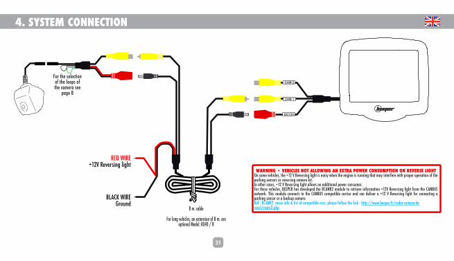
RED WIRE
+12V Reversing light
BLACK WIRE
Ground
CAM 2
DC12V
CAM 1
8 m. cable
For long vehicles, an extension of 8 m. are optional Model: RX40 / 8
O9JFAF?���N=@A;D=K�FGL�9DDGOAF?�9F�=PLJ9�HGO=J�;GFKMEHLAGF�GF�J=N=JK=�DA?@LOn some vehicles, the +12 V Reversing light is noisy when the engine is running that may interfere with proper operation of the
parking sensors or reversing camera kit.
In other cases, +12 V Reversing light allows no additional power consumer.
For these vehicles, BEEPER has developed the RCANR2 module to retrieve information +12V Reversing light from the CANBUS
network. This module connects to the CANBUS compatible carrier and can deliver a +12 V Reversing light for connecting a
parking sensor or a backup camera
Ref : RCANR2, more info & list of compatible cars, please follow the link : http://www.beeper.fr/radar-camera-de-
recul/rcanr2.php
For the selection
of the loops of
the camera see
page 8

22
4. SYSTEM CONNECTION (if additional camera)
DC12V
CAM 1
Video
Alimentation
Video
AlimentationBack cameraCAM1
Monitor
RED WIRE+12V Reversing light
BLACK WIREGround
Do not connect & ISOLATEPlease protect this connector so that it does not
come into contact with a metal part of the vehicle
CAM 2
Vidéo
Alimentation
RED+12 After ignition
BLACKGROUND
Front camera
CAM2
Switch (2) control of the front
camera and the screen
loop:
��O`al]� )!�eajjgj�[Ye]jY
O9JFAF?���N=@A;D=K�FGL�9DDGOAF?�9F�=PLJ9�HGO=J�;GFKMEHLAGF�GF�J=N=JK=�DA?@L
On some vehicles, the +12 V Reversing light is noisy when the engine is running
that may interfere with proper operation of the parking sensors or reversing
camera kit.
In other cases, +12 V Reversing light allows no additional power consumer.
For these vehicles, BEEPER has developed the RCANR2 module to retrieve
information +12V Reversing light from the CANBUS network. This module connects
to the CANBUS compatible carrier and can deliver a +12 V Reversing light for
connecting a parking sensor or a backup camera
Ref : RCANR2, more info & list of compatible cars, please follow the link :
http://www.beeper.fr/radar-camera-de-recul/rcanr2.php
For the selection
of the loops of
the camera see
page 8
8 m. cable
For long vehicles, an extension of 8 m. are optional Model: RX40 / 8
For the selection
of the loops of
the camera see
page 8
6. INSTALLATION DE LA CAMERA
23
OPTIONS CAMERA : TEMPLATE & REVERSE IMAGE
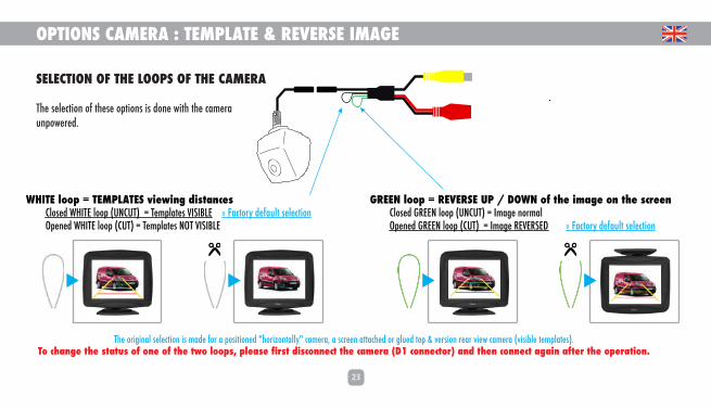
SELECTION OF THE LOOPS OF THE CAMERA
The selection of these options is done with the cameraunpowered.
GREEN loop = REVERSE UP / DOWN of the image on the screen Closed GREEN loop (UNCUT) = Image normal Opened GREEN loop (CUT) = Image REVERSED » Factory default selection
WHITE loop = TEMPLATES viewing distances Closed WHITE loop (UNCUT) = Templates VISIBLE » Factory default selection Opened WHITE loop (CUT) = Templates NOT VISIBLE
The original selection is made for a positioned "horizontally" camera, a screen attached or glued top & version rear view camera (visible templates).To change the status of one of the two loops, please first disconnect the camera (D1 connector) and then connect again after the operation.

24
95 mm
76 mm88 mm
60 mm
24 mm
89 mm
5. MONITOR INSTALLATION
Thanks to its rotating bracket and sticker, RW075LDV monitor can be placed anywhere in your vehicle. The ideal position of your monitor is on the top of car roof near rearview mirror. If this position is not possible or not appropriate, you can set the monitor on the dashboard so visible during reversing. Make sure that the monitor is not too visible from outside the vehicle so as not to attract thieves.
The screen is fixed by an adhesive on a backing high strength double-sided. We advise you to clean and degrease the surface before bonding.
We recommend the use of a primary (our ref: RX-PR01 not supplied in this kit) allows maximum adhesion before bonding double-sided. The primary must be applied on both parts receiving the sticker : monitor bracket + dashboard or rooftop part where the bracket will be stuck.
The rotating bracket allows you to use your screen in all directions, just rotate the image using the bottom button on the right side of the screen.
The wiring must be concealed in the amounts of windshield under the dashboard, under the trim and must not be apparent. There must not interfere with the driver operation, put it away from heating elements.
25
6. CAMERA INSTALLATION
GROUND GROUND
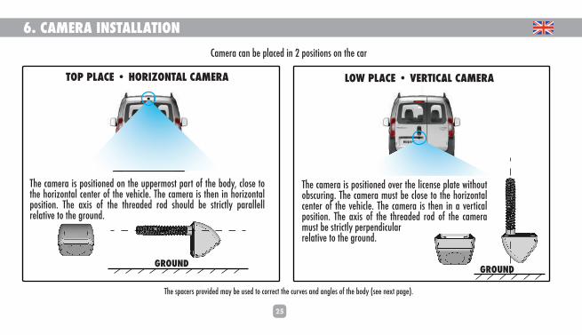
Camera can be placed in 2 positions on the car
The spacers provided may be used to correct the curves and angles of the body (see next page).
TOP PLACE • HORIZONTAL CAMERA
The camera is positioned on the uppermost part of the body, close to the horizontal center of the vehicle. The camera is then in horizontal position. The axis of the threaded rod should be strictly parallell relative to the ground.
LOW PLACE • VERTICAL CAMERA
The camera is positioned over the license plate without obscuring. The camera must be close to the horizontal center of the vehicle. The camera is then in a vertical position. The axis of the threaded rod of the camera must be strictly perpendicularrelative to the ground.
26
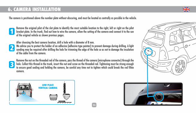
6. CAMERA INSTALLATIONThe camera is positioned above the number plate without obscuring, and must be located as centrally as possible in the vehicle.
Remove the original pilot of the slot plate to identify the most suitable location to the right, left or right on the pilot bracket plate. In the trunk, find out how to wire the camera, allow the setting of the camera and connect it to the son of the original vehicle as shown previous pages.
After choosing the best camera location, drill a hole with a diameter of 8 mm.We advise you to protect the holder of an adhesive (adhesive type painter) to prevent damage during drilling. A light sanding may be required after drilling the hole for trimming the edge of the hole so as not to damage the insulation of the cable from the camera.
Remove the nut on the threaded rod of the camera, pass the thread of the camera (microphone connector) through the hole. Collect this thread in the trunk, insert the nut and screw on the threaded rod. Tightening must be strong enough to ensure good sealing and holding the camera, be careful any time not to tighten which could break the rod filtée camera.
1
2
3
GROUND
LOW PLACEVERTICAL CAMERA

27
6. CAMERA INSTALLATION
1
2
3
GROUND
TOP PLACEHORIZONTAL CAMERA
The camera is positioned above the number plate without obscuring, and must be located as centrally as possible in the vehicle. Remove the original pilot of the slot plate to identify the most suitable location to the right, left or right on the pilot bracket plate. In the trunk, find out how to wire the camera, allow the setting of the camera and connect it to the son of the original vehicle as shown previous pages.
After choosing the best camera location, drill a hole with a diameter of 6 mm.We advise you to protect the holder of an adhesive (adhesive type painter) to prevent damage during drilling. A light sanding may be required after drilling the hole for trimming the edge of the hole so as not to damage the insulation of the cable from the camera.
Remove the nut on the threaded rod of the camera, pass the thread of the camera (microphone connector) through the hole. Collect this thread in the trunk, insert the nut and screw on the threaded rod. Tightening must be strong enough to ensure good sealing and holding the camera, be careful any time not to tighten which could break the rod filtée camera.
28
7. USER INSTRUCTION
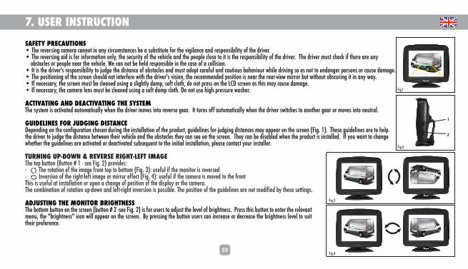
SAFETY PRECAUTIONS ��L`]�j]n]jkaf_�[Ye]jY�[Yffgl�af�Yfq�[aj[meklYf[]k�Z]�Y�kmZklalml]�^gj�l`]�na_adYf[]�Yf\�j]khgfkaZadalq�g^�l`]�\jan]j&��L`]�j]n]jkaf_�Ya\�ak�^gj�af^gjeYlagf�gfdq$�l`]�k][mjalq�g^�l`]�n]`a[d]�Yf\�l`]�h]ghd]�[dgk]�lg�al�ak�l`]�j]khgfkaZadalq�g^�l`]�\jan]j&��L`]�\jan]j�emkl�[`][c�a^�l`]j]�Yj]�Yfq�����gZklY[d]k�gj�h]ghd]�f]Yj�l`]�n]`a[d]&�O]�[Yf�fgl�Z]�`]d\�j]khgfkaZd]�af�l`]�[Yk]�g^�Y�[gddakagf&��Al�ak�l`]�\jan]j�k�j]khgfkaZadalq�lg�bm\_]�l`]�\aklYf[]�g^�gZklY[d]k�Yf\�emkl�Y\ghl�[Yj]^md�Yf\�[Ymlagmk�Z]`Ynagmj�o`ad]�\janaf_�kg�Yk�fgl�lg�]f\Yf_]j�h]jkgfk�gj�[Ymk]�\YeY_]&��L`]�hgkalagfaf_�g^�l`]�k[j]]f�k`gmd\�fgl�afl]j^]j]�oal`�l`]�\jan]j�k�nakagf$�l`]�j][gee]f\]\�hgkalagf�ak�f]Yj�l`]�j]Yj%na]o�eajjgj�Zml�oal`gml�gZk[mjaf_�al�af�Yfq�oYq&��A^�f][]kkYjq$�l`]�k[j]]f�emkl�Z]�[d]Yf]\�mkaf_�Y�kda_`ldq�\Yeh$�kg^l�[dgl`$�\g�fgl�hj]kk�gf�l`]�D;<�k[j]]f�Yk�l`ak�eYq�[Ymk]�\YeY_]&��A^�f][]kkYjq$�l`]�[Ye]jY�d]fk�emkl�Z]�[d]Yf]\�mkaf_�Y�kg^l�\Yeh�[dgl`&�<g�fgl�mk]�`a_`�hj]kkmj]�oYk`]j&
ACTIVATING AND DEACTIVATING THE SYSTEML`]�kqkl]e�ak�Y[lanYl]\�YmlgeYla[Yddq�o`]f�l`]�\jan]j�egn]k�aflg�j]n]jk]�_]Yj&��Al�lmjfk�g^^�YmlgeYla[Yddq�o`]f�l`]�\jan]j�koal[`]k�lg�Yfgl`]j�_]Yj�gj�egn]k�aflg�f]mljYd&
GUIDELINES FOR JUDGING DISTANCE<]h]f\af_�gf�l`]�[gf^a_mjYlagf�[`gk]f�\mjaf_�l`]�afklYddYlagf�g^�l`]�hjg\m[l$�_ma\]daf]k�^gj�bm\_af_�\aklYf[]k�eYq�Yhh]Yj�gf�l`]�k[j]]f� >a_&�)!&��L`]k]�_ma\]daf]k�Yj]�lg�`]dh�l`]�\jan]j�lg�bm\_]�l`]�\aklYf[]�Z]lo]]f�l`]aj�n]`a[d]�Yf\�l`]�gZklY[d]k�l`]q�[Yf�k]]�gf�l`]�k[j]]f&��L`]q�[Yf�Z]�\akYZd]\�o`]f�l`]�hjg\m[l�ak�afklYdd]\&��A^�qgm�oYfl�lg�[`Yf_]�o`]l`]j�l`]�_ma\]daf]k�Yj]�Y[lanYl]\�gj�\]Y[lanYl]\�kmZk]im]fl�lg�l`]�afalaYd�afklYddYlagf$�hd]Yk]�[gflY[l�qgmj�afklYdd]j&
TURNING UP-DOWN & REVERSE RIGHT-LEFT IMAGE L`]�lgh�Zmllgf� :mllgf���)�%�k]]�>a_&�*!�hjgna\]k2�%���������L`]�jglYlagf�g^�l`]�aeY_]�^jge�lgh�lg�Zgllge� >a_&�+!2�mk]^md�a^�l`]�egfalgj�ak�j]n]jk]\�%���������Afn]jkagf�g^�l`]�ja_`l%d]^l�aeY_]�gj�eajjgj�]^^][l� >a_&�,!2�mk]^md�a^�l`]�[Ye]jY�ak�egn]\�lg�l`]�^jgfl�L`ak�ak�mk]^md�Yl�afklYddYlagf�gj�mhgf�Y�[`Yf_]�g^�hgkalagf�g^�l`]�\akhdYq�gj�l`]�[Ye]jY&�L`]�[geZafYlagf�g^�jglYlagf�mh%\gof�Yf\�d]^l%ja_`l�afn]jkagf�ak�hgkkaZd]&�L`]�hgkalagf�g^�l`]�_ma\]daf]k�Yj]�fgl�eg\a^a]\�Zq�l`]k]�k]llaf_k&
ADJUSTING THE MONITOR BRIGHTNESSL`]�Zgllge�Zmllgf�gf�l`]�k[j]]f� Zmllgf���*�%k]]�>a_&�*!�ak�^gj�mk]jk�lg�Y\bmkl�l`]�d]n]d�g^�Zja_`lf]kk&��Hj]kk�l`ak�Zmllgf�lg�]fl]j�l`]�j]d]nYfl�e]fm$�l`]��Zja_`lf]kk��a[gf�oadd�Yhh]Yj�gf�l`]�k[j]]f&��:q�hj]kkaf_�l`]�Zmllgf�mk]jk�[Yf�af[j]Yk]�gj�\][j]Yk]�l`]�Zja_`lf]kk�d]n]d�lg�kmal�l`]aj�hj]^]j]f[]&
1
2
>a_&*
>a_&)
>a_&+
>a_&,

29
8. TECHNICAL DATACAMERA��Hgo]j2�)(&-�lg�)-&-�N&� fgeafYd�)*�N!��;gfkmehlagf2�4(&.�O�eYp&��K]fkalanalq2�-(�\:��Fa_`l�Nakagf2�(&*�dme]fk�eaf��AH./�jYl]\� \g�fgl�[d]Yf�oal`�Y�hj]kkmj]�oYk`]j!��Daealk�Yd]jl�kmh]jaehgk]\�aeY_]� k]d][lYZd]�dggh!��EYpaeme�`gjargflYd�Yf_d]�)-(����EYp�N]jla[Yd�9f_d]2�))(����@mea\alq2�)��lg�1.���^gf[lagff]efl�L��2�%*-���;�'�#.-���;��KlgjY_]�l]eh2�%+(���;�'�#/(���;
TECHNICAL ASSISTANCE>gj�l][`fa[Yd�af^gjeYlagf�hd]Yk]�[gflY[l�gmj�l][`fa[Yd�`gldaf]�gh]f�^jge�Egf\Yq�lg�>ja\Yq�^jge�1Ye�lg�)*he�Yf\�),he�lg�)0he
LCD MONITOR��Hgo]j2�)(&-�lg�)-&-�N&� fgeafYd�)*�N!��Hgo]j�[gfkmehlagf2�4+�O�eYp&��>gjeYl2�,2+��<aY_gfYd2�+&-�� 0&01�[e!��;gfljYkl2�+-(2)��J]kgdmlagf2�1.(�p�,.0�hap]dk��Kqkl]e2�H9D�'�FLK;�Ymlg%koal[`af_��@mea\alq2�)��lg�1.���^gf[lagff]efl�L��2�%*-���;�'�#.-���;��KlgjY_]�l]eh2�%+(���;�'�#/(���;
(&+,�Ē�LL;�h]j�eafml]

30
9. DECLARATION OF CONFORMITYWe IXIT
� **0�Jm]�\]�d�9f[a]ff]�<akladd]ja]�� .1,((�?D=AR �>jYf[]�
<][dYj]�mf\]j�gmj�kgd]�j]khgfkaZadalq�l`Yl�l`]�hjg\m[lRW037-PLqh]2�Rear View CameraLg�o`a[`�l`ak�\][dYjYlagf�Yhhda]k$�[gehdq�oal`�klYf\Yj\k���fgjeYlan]�\g[me]flk2=eYjc�*((1')1�=;�Yk�Fg&�]*,(+)0,0�YhhjgnYdJG@K�Y[[gj\af_�lg�<aj][lan]�*((*'1-'=;J=9;@
Mf\]j�l`]�hjgnakagfk�g^�*)'(1'*((/$?d]ar$�Bmdq�*-$�*()+
w
L`a]jjq�:addYm?]f]jYd�eYfY_]j
GARANTIE
GUARANTEE YEARS3
e24 031848
RoHS
31
MANUAL DE USO
Introducción ¡Gracias por utilizar una solución BEEPER para la seguridad y el confort en su vehículo! Nuestros innovadores productos han sido diseñados para ofrecerle varios años de tranquilidad. Nuestro servicio técnico está a su disposición para brindarle cualquier información adicional.
El sistema de vídeo para marcha atrás RW037-P es un producto electrónico y su instalación requiere de los conocimientos de un electricista de automotores. Aunque este tipo de instalación universal no sea para nada compleja, le aconseja-mos recurrir a un profesional para no dañar su vehículo.
Esperamos que nuestro producto BEEPER RW037-P le satisfaga plenamente y mejore la seguridad de su vehículo.
MÁS PRODUCTOS, MÁS INFORMACIÓNES

32
RESUMEN
1. Antes de la instalación................................................................................................................................................................................................... P.332. Funciones principales .................................................................................................................................................................................................... P.343. Composición del kit ........................................................................................................................................................................................................ P.344. Conexión del sistema .................................................................................................................................................................................................. P.355. Instalación del monitor ................................................................................................................................................................................................... P.386. Instalación de la cámara ............................................................................................................................................................................................. P.397. Uso del sistema ........................................................................................................................................................................................................... P.428. Característacas técnicas......................................................................................................................................................................................... ......... P.439. Certificaciones ................................................................................................................................................................................................................. P.44
Continuar el descubrimiento enwww.beeper.fr

33
1. ANTES DE LA INSTALACIÓN
PrecaucionesAntes de instalar este sistema, le recomendamos seguir estas indicaciones:• Este sistema funciona con corriente continua de 12 V (12 Vcc). Verifique la polaridad de cada cable.• Antes de instalarlo, verifique que funcionen correctamente todos los componentes del vehículo, como el contacto y el arranque del motor, el encendido de luces (de cruce, de carretera, traseras e intermitentes), la calefacción, el aire acondicionado, el bloqueo de puertas. Después de la instalación, compruebe que todos esos componentes funcionen.• Cuando conecte la MASA general del sistema, es muy importante que verifique que dicha masa sea abierta y totalmente estable (sin fugas).• Asegúrese de que todos los cables que pasen por lugares estrechos estén protegidos con cinta aisladora para evitar que sufran una excesiva torsión y que se deteriore la funda protectora de plástico con el consecuente riesgo de falsos contactos.• Procure que los cables del sistema y todos los accesorios de seguridad se ubiquen de la manera más disimulada posible en el vehículo. Recuerde que está instalando un sistema de seguridad.• Utilice un multímetro digital para verificar la polaridad de cada uno de los cables.• Si el vehículo tiene una radio con codificación, no desconecte la batería• Si el vehículo está equipado con AIRBAG, no desconecte la batería del vehículo ni haga las conexiones sin tener certeza de qué cables está conectando.• Quite el fusible de la luz de techo cuando instale el sistema para que la batería no se descargue al estar las puertas abiertas.• El sistema de vídeo para marcha atrás es una herramienta de información. La seguridad del vehículo y de las personas en sus inmediaciones es responsabilidad exclusiva del conductor, que tiene la obligación de mirar si hay obstáculos o personas cerca de su vehículo. En caso de colisión, no se podrá imputar responsabilidad alguna a nuestra empresa.
VEHÍCULOS MULTIPLEXADOSEl sistema BEEPER- RW037-P es compatible con todos los vehículos multiplexados. Toda la información requerida para la conexión pasa por cables de polaridad normal (+ o -), por los que no se transmite información codificada (multiplexado BUSCAN, VAN u otra codificación). No corte ni toque un cable multiplexado bajo ninguna circunstancia. EN CUALQUIER CASO, ES INÚTIL Y SE DESACONSEJA CORTAR EL CABLE ORIGINAL DEL VEHÍCULO. SOLO DEBE HACER UN EMPALME Y RECUPERAR LA SEÑAL POSITIVA O NEGATIVA QUE SE TRANSMITE POR ESE CABLE. Si necesita más información o asesoramiento, comuníquese con nuestro servicio técnico : [email protected]

34
2. PRINCIPALES FUNCIONES• El RW037-P es un kit de vídeo para marcha atrás destinado a vehículos de pequeñas o medianas dimensiones (automóviles, monovolúmenes, coches familiares, 4x4…).• El sistema de vídeo para marcha atrás se activa automáticamente al poner la marcha atrás.• El monitor le permitirá ver los puntos ciegos traseros para maniobrar en marcha atrás con total seguridad.• El sistema se desactivará en cuanto quite la marcha atrás.• Las líneas de colores de la plantilla le permitirán calcular las distancias al maniobrar. (Esta función se puede desactivar).
3. COMPOSICIÓN DEL KIT
CBA MONITOR CABLE CÁMARA
35
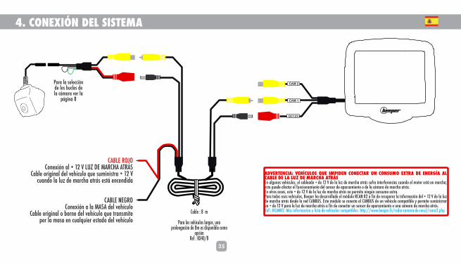
4. CONEXIÓN DEL SISTEMA
CABLE ROJOConexión al + 12 V LUZ DE MARCHA ATRÁS
Cable original del vehículo que suministra + 12 V cuando la luz de marcha atrás está encendida
CABLE NEGROConexión a la MASA del vehículo
Cable original o borne del vehículo que transmite por la masa en cualquier estado del vehículo
CAM 2
DC12V
CAM 1
Cable : 8 m
Para los vehículos largos, una prolongación de 8m es disponible como
opción Ref : RX40/8
ADVERTENCIA: VEHÍCULOS QUE IMPIDEN CONECTAR UN CONSUMO EXTRA DE ENERGÍA AL CABLE DE LA LUZ DE MARCHA ATRÁSEn algunos vehículos, el cableado + de 12 V de la luz de marcha atrás sufre interferencias cuando el motor está en marcha; esto puede afectar el funcionamiento del sensor de aparcamiento o de la cámara de marcha atrás.En otros casos, este + de 12 V de la luz de marcha atrás no permite ningún consumo extra.Para todos esos vehículos, Beeper ha desarrollado el módulo RCAN R2 a fin de recuperar la información del + 12 V de la luz de marcha atrás desde la red CANBUS. Este módulo se conecta al CANBUS de un vehículo compatible y permite suministrar un + de 12 V para la luz de marcha atrás a fin de conectar un sensor de aparcamiento o una cámara de marcha atrás.Ref.: RCANR2. Más información y lista de vehículos compatibles: http://www.beeper.fr/radar-camera-de-recul/rcanr2.php
Para la selección de los bucles de la cámara ver la
página 8
DC
12
V
CA
M 1
36
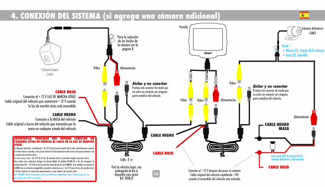
4. CONEXIÓN DEL SISTEMA (si agrega una cámara adicional)
Cable : 8 m
Para los vehículos largos, una prolongación de 8m es disponible como opción
Ref : RX40/8
Vídeo Alimentación
CABLE ROJOConexión al + 12 V LUZ DE MARCHA ATRÁS
Cable original del vehículo que suministra + 12 V cuando la luz de marcha atrás está encendida
CABLE NEGROConexión a la MASA del vehículo
Cable original o borne del vehículo que transmite por la masa en cualquier estado del vehículo
Aislar y no conectarProteja este conector de modo que no entre en contacto con ninguna parte metálica del vehículo.
Pantalla
Vídeo
Alimentación
Cámara delanteraCAM2
Bucle :• Blanco (1) : Espejo de la cámara• Azul (2) : plantilla
Conectar al + 12 V después de poner el contacto Cable original del vehículo expidiendo +12V
cuando el encendido del vehículo esta activado
CABLE NEGROMASA
Interruptor(2) de control de la cámara delantera y del monitor
Cámara traseraCAM1
ADVERTENCIA: VEHÍCULOS QUE IMPIDEN CONECTAR UN CONSUMO EXTRA DE ENERGÍA AL CABLE DE LA LUZ DE MARCHA ATRÁSEn algunos vehículos, el cableado + de 12 V de la luz de marcha atrás sufre interferencias cuando el motor está en marcha; esto puede afectar el funcionamiento del sensor de aparcamiento o de la cámara de marcha atrás.En otros casos, este + de 12 V de la luz de marcha atrás no permite ningún consumo extra.Para todos esos vehículos, Beeper ha desarrollado el módulo RCAN R2 a fin de recuperar la información del + 12 V de la luz de marcha atrás desde la red CANBUS. Este módulo se conecta al CANBUS de un vehículo compatible y permite suministrar un + de 12 V para la luz de marcha atrás a fin de conectar un sensor de aparcamiento o una cámara de marcha atrás.Ref.: RCANR2. Más información y lista de vehículos compatibles: http://www.beeper.fr/ra-dar-camera-de-recul/rcanr2.php
Para la selección de los bucles de la cámara ver la
página 8
CA
M 2
Vídeo
CABLE ROJO
Vídeo Alimentación
Aislar y no conectarProteja este conector de modo que no entre en contacto con ninguna parte metálica del vehículo.
CABLE NEGRO
CABLE ROJO
6. INSTALLATION DE LA CAMERA
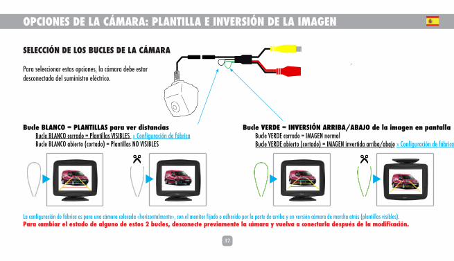
Bucle VERDE = INVERSIÓN ARRIBA/ABAJO de la imagen en pantalla Bucle VERDE cerrado = IMAGEN normal Bucle VERDE abierto (cortado) = IMAGEN invertida arriba/abajo » Configuración de fábrica
Bucle BLANCO = PLANTILLAS para ver distancias Bucle BLANCO cerrado = Plantillas VISIBLES » Configuración de fábrica Bucle BLANCO abierto (cortado) = Plantillas NO VISIBLES
37
OPCIONES DE LA CÁMARA: PLANTILLA E INVERSIÓN DE LA IMAGEN
SELECCIÓN DE LOS BUCLES DE LA CÁMARA
Para seleccionar estas opciones, la cámara debe estar desconectada del suministro eléctrico.
La configuración de fábrica es para una cámara colocada «horizontalmente», con el monitor fijado o adherido por la parte de arriba y en versión cámara de marcha atrás (plantillas visibles).Para cambiar el estado de alguno de estos 2 bucles, desconecte previamente la cámara y vuelva a conectarla después de la modificación.
38
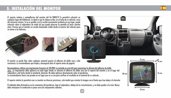
95 mm
76 mm88 mm
60 mm
24 mm
89 mm
5. INSTALACIÓN DEL MONITOR
El soporte rotativo y autoadhesivo del monitor del kit RW037-P le permitirá colocarlo en cualquier lugar del habitáculo. Lo ideal es que lo ubique arriba, en el techo de su vehículo, cerca del retrovisor interior. Si no es posible o no le resulta conveniente instalarlo en ese lugar, puede colocarlo sobre el salpicadero de modo tal que pueda observar la pantalla al hacer marcha atrás. Procure que el monitor no resulte demasiado visible desde el exterior del vehículo para no atraer a los ladrones.
El monitor se puede fijar sobre cualquier material gracias al adhesivo de doble cara y alta resistencia. Le recomendamos que limpie y desengrase bien el soporte antes de pegarlo.
Recomendamos utilizar una imprimación (nuestra ref. RX-PR01 no incluida en este kit) para maximizar la eficacia del adhesivo de doble cara. La imprimación debe aplicarse en cada lugar donde se colocará el adhesivo de doble cara (en el soporte del monitor y en el lugar del salpicadero o del techo donde lo instalará). Atención: No debe aplicarse directamente sobre el parabrisas.Le recomendamos hacer una prueba en un lugar que no se vea para verificar el resultado en el material de su vehículo.
El soporte rotativo le permitirá usar su monitor en diversas posiciones, solo tendrá que orientar la imagen con el botón que trae abajo a la derecha.
El cableado debe disimularse en los montantes del parabrisas, bajo el salpicadero, debajo de los revestimientos, y no debe quedar a la vista. Nunca debe entorpecer la conducción ni pasar cerca de componentes calientes.
39
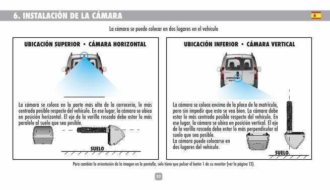
6. INSTALACIÓN DE LA CÁMARA
UBICACIÓN SUPERIOR • CÁMARA HORIZONTAL
La cámara se coloca en la parte más alta de la carrocería, lo más centrada posible respecto del vehículo. En ese lugar, la cámara se ubica en posición horizontal. El eje de la varilla roscada debe estar lo más paralelo al suelo que sea posible.
UBICACIÓN INFERIOR • CÁMARA VERTICAL
La cámara se coloca encima de la placa de la matrícula, pero sin impedir que esta se vea bien. La cámara debe estar lo más centrada posible respecto del vehículo. En ese lugar, la cámara se ubica en posición vertical. El eje de la varilla roscada debe estar lo más perpendicular al suelo que sea posible.La cámara puede colocarse en dos lugares del vehículo.SUELO
SUELO
La cámara se puede colocar en dos lugares en el vehículo
Para cambiar la orientación de la imagen en la pantalla, solo tiene que pulsar el botón 1 de su monitor (ver la página 13).
40
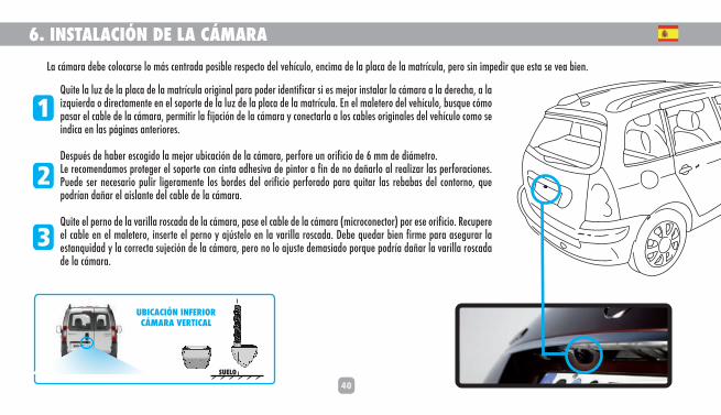
6. INSTALACIÓN DE LA CÁMARA
Quite la luz de la placa de la matrícula original para poder identificar si es mejor instalar la cámara a la derecha, a la izquierda o directamente en el soporte de la luz de la placa de la matrícula. En el maletero del vehículo, busque cómo pasar el cable de la cámara, permitir la fijación de la cámara y conectarla a los cables originales del vehículo como se indica en las páginas anteriores.
Después de haber escogido la mejor ubicación de la cámara, perfore un orificio de 6 mm de diámetro.Le recomendamos proteger el soporte con cinta adhesiva de pintor a fin de no dañarlo al realizar las perforaciones. Puede ser necesario pulir ligeramente los bordes del orificio perforado para quitar las rebabas del contorno, que podrían dañar el aislante del cable de la cámara.
Quite el perno de la varilla roscada de la cámara, pase el cable de la cámara (microconector) por ese orificio. Recupere el cable en el maletero, inserte el perno y ajústelo en la varilla roscada. Debe quedar bien firme para asegurar la estanquidad y la correcta sujeción de la cámara, pero no lo ajuste demasiado porque podría dañar la varilla roscada de la cámara.
1
2
3
SUELO
UBICACIÓN INFERIOR CÁMARA VERTICAL
La cámara debe colocarse lo más centrada posible respecto del vehículo, encima de la placa de la matrícula, pero sin impedir que esta se vea bien.
41
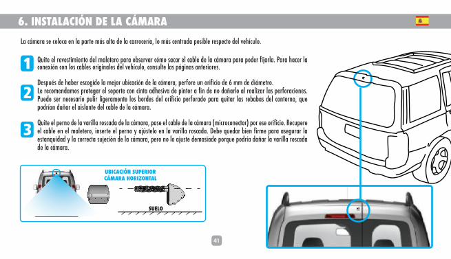
6. INSTALACIÓN DE LA CÁMARALa cámara se coloca en la parte más alta de la carrocería, lo más centrada posible respecto del vehículo.
Quite el revestimiento del maletero para observar cómo sacar el cable de la cámara para poder fijarla. Para hacer la conexión con los cables originales del vehículo, consulte las páginas anteriores.
Después de haber escogido la mejor ubicación de la cámara, perfore un orificio de 6 mm de diámetro.Le recomendamos proteger el soporte con cinta adhesiva de pintor a fin de no dañarlo al realizar las perforaciones. Puede ser necesario pulir ligeramente los bordes del orificio perforado para quitar las rebabas del contorno, que podrían dañar el aislante del cable de la cámara.
Quite el perno de la varilla roscada de la cámara, pase el cable de la cámara (microconector) por ese orificio. Recupere el cable en el maletero, inserte el perno y ajústelo en la varilla roscada. Debe quedar bien firme para asegurar la estanquidad y la correcta sujeción de la cámara, pero no lo ajuste demasiado porque podría dañar la varilla roscada de la cámara.
1
2
3
SUELO
UBICACIÓN SUPERIOR CÁMARA HORIZONTAL

42
7. USO DEL SISTEMAPRECAUCIONES DE USO • La cámara de marcha atrás no puede, en ningún caso, suplir la atenta vigilancia y la responsabilidad del conductor.• El sistema de vídeo para marcha atrás es una herramienta de información. La seguridad del vehículo y de las personas en sus inmediaciones es responsabilidad exclusiva del conductor, que tiene la obligación de mirar si hay obstáculos o personas cerca de su vehículo. En caso de colisión, no se podrá imputar responsabilidad alguna a nuestra empresa.• Es responsabilidad exclusiva del conductor evaluar el riesgo que representan los obstáculos y adoptar una actitud prudente y atenta cuando conduce para no poner en peligro a las personas ni provocar daños materiales.• El monitor debe ubicarse de tal modo que no obstruya la visión del conductor. Se recomienda colocarlo cerca del retrovisor interior, pero sin impedir que este se vea bien.• El monitor debe limpiarse con un paño suave ligeramente humedecido. Procure no presionar la pantalla LCD para que no se dañe.• La lente de la cámara debe limpiarse con un paño suave ligeramente humedecido. No lavar con manguera de alta presión.
ACTIVACIÓN Y DESACTIVACIÓN DEL SISTEMAEl sistema se activa automáticamente al poner la marcha atrás del vehículo. Se desactiva automáticamente al pasar a cualquier otra marcha o a punto muerto.
GABARITS DE VISUALISATION DES DISTANCESK]dgf�d]�lqh]�\]�[gf^a_mjYlagf�jYdak]�dgjk�\]�d�afklYddYlagf�\m�hjg\mal$�\]k�da_f]k�\]�_YZYjal�\]�nakmYdakYlagf�\]k�\aklYf[]k�YhhYjYakk]fl�]f�af[jmklYlagf�kmj�d�[jYf� >a_&�)!&�;]�_YZYjal�]kl�klja[l]e]fl�af\a[Yla^$�ad�ngmk�YhhYjla]fl�\]�bm_]j�\]k�\aklYf[]k�\]k�gZklY[d]k�nakaZd]k�§�d�[jYf&�;]k�da_f]k�\]�_YZYjal�h]mn]fl�¯lj]�\kY[lan]k�§�d�afklYddYlagf�\m�hjg\mal&�Ka�ngmk�kgm`Yala]r�eg\a^a]j�d�Y[lanYlagf�gm�\kY[lanYlagf�\]k�da_f]k�\]�_YZYjal�mdlja]mj]e]fl�§�d�afklYddYlagf�afalaYd]$�fgmk�ngmkhjagfk�\]�ngmk�jYhhjg[`]j�\]�nglj]�afklYddYl]mj� ngaj�hY_]�0!&
PLANTILLAS DE VISUALIZACIÓN DE DISTANCIAS=d�Zgl¶f�kmh]jagj� Zgl¶f�f&��)$�n]j�^a_mjY�*!�h]jeal]2%��������jglYj�dY�aeY_]f�\]�YjjaZY�`Y[aY�YZYbg� ^a_mjY�+!$�dg�im]�j]kmdlY�»lad�ka�dY�hYflYddY�]kl¦�afn]jla\Y3�%��������afn]jlaj�dY�aeY_]f�\]�\]j][`Y�Y�arima]j\Y�g�[gf�]^][lg�]kh]bg� ^a_mjY�,!$�dg�im]�j]kmdlY�»lad�ka�dY�[¦eYjY�]kl¦�[gdg[Y\Y�]f�dY�hYjl]�delantera.Esta función se utiliza al realizar la instalación o en caso de cambiar la posición del monitor o de la cámara.Es posible combinar la rotación arriba-abajo y la inversión de derecha-izquierda. Estos ajustes no modifican la posición de las líneas de las plantillas.
BRILLO DE LA PANTALLA=d�Zgl¶f� af^]jagj�\]d�egfalgj� Zgl¶f�f&*$�n]j� ^a_mjY�*!�h]jeal]�YbmklYj�]d�Zjaddg&�Hmdk]�]k]�Zgl¶f�hYjY� [ge]frYj�]d�Ybmkl]&�=d� a[gfg�correspondiente aparecerá en pantalla y podrá aumentar o bajar el nivel de brillo pulsando varias veces en dicho botón.
1
2
>a_&*
>a_&)
>a_&+
>a_&,
43
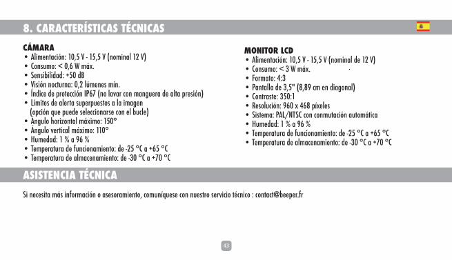
8. CARACTERÍSTICAS TÉCNICASCÁMARA• Alimentación: 10,5 V - 15,5 V (nominal 12 V)• Consumo: < 0,6 W máx.• Sensibilidad: +50 dB• Visión nocturna: 0,2 lúmenes mín.• Índice de protección IP67 (no lavar con manguera de alta presión)• Límites de alerta superpuestos a la imagen (opción que puede seleccionarse con el bucle)• Ángulo horizontal máximo: 150°• Ángulo vertical máximo: 110°• Humedad: 1 % a 96 %• Temperatura de funcionamiento: de -25 °C a +65 °C• Temperatura de almacenamiento: de -30 °C a +70 °C
ASISTENCIA TÉCNICASi necesita más información o asesoramiento, comuníquese con nuestro servicio técnico : [email protected]
MONITOR LCD• Alimentación: 10,5 V - 15,5 V (nominal de 12 V)• Consumo: < 3 W máx.• Formato: 4:3• Pantalla de 3,5" (8,89 cm en diagonal)• Contraste: 350:1• Resolución: 960 x 468 píxeles• Sistema: PAL/NTSC con conmutación automática• Humedad: 1 % a 96 %• Temperatura de funcionamiento: de -25 °C a +65 °C• Temperatura de almacenamiento: de -30 °C a +70 °C
44
9. DECLARACIÓN DE CONFORMIDAD Nosotros IXIT � � **0�Jm]�\]�d�9f[a]ff]�<akladd]ja]�� � .1,((�?D=AR �>jYf[aY�
<][dYjYegk�ZYbg�fm]kljY�»fa[Y�j]khgfkYZada\Y\�im]�]d�hjg\m[lg�RW037-P Lahg�2�Cámara de marcha atrás =kl]�kakl]eY�`Y�ka\g�hjgZY\g�q�[]jla^a[Y\g�[gf^gje]�Y�dYk�ka_ma]fl]k�fgjeYk2=eYjc�*((1')1�=;�[gf�]d�f»e]jg�\]�`gegdg_Y[a¶f�]*,(+)0,0JG@K�k]_»f�dY�\aj][lanY�*((*'1-';=J=9;@
;gf�dYk�\akhgka[agf]k�\]d��*)'(1'*((/$?d]ar$�*-��\]�bmdag�\]�*()+���������������������������������������������������������
L`a]jjq�:addYm��<aj][lgj�_]f]jYd�
GARANTIE
GARANTÍA AÑOS3
e24 031848
RoHS


©Copyright IXIT BEEPER 2013. La reproduction des données, informations, descriptions, photos de ce
document est soumise à l'autorisation préalable d'IXIT BEEPER. Toutes les informations indiquées dans
ce manuel sont indicatives et n'ont pas de caractère contractuel et sont susceptibles d'être modifiées
sans préavis. Ces données sont sous réserves de vérification de la compatibilité avec votre véhicule à
faire par vos soins. IXIT BEEPER se dégage de toute responsabilité en cas de dégradation d'un véhicule
suite à l'installation de ce produit.
© Copyright IXIT Beeper 2013. The reproduction of data, information, descriptions, photos of this
document is subject to prior authorization IXIT Beeper. All information in this manual are indicative
and not of a contractual nature and are subject to change without notice. These datas are in reserve of
prior check of compatibility with your vehicle to do by yourself. IXIT Beeper disclaims any liability for
damage to a vehicle after the installation of this product.
Plus d'infos, plus de produitsMore info, more products
www.beeper.fr
IXIT BEEPER**0�Jm]�\]�A�9f[a]ff]�<akladd]ja]���HYj]�\]k�?jaddgfk
.1,((�?D=AR ���>jYf[]
;YhalYd2�.)�(((�=���J;K�,+/�.1,�(/0�Nadd]^jYe2`]�LYjYj]���Kaj]l�,+/�.1,�(/0�(((*/F�LN9�2�>J�+.�,+/�.1,�(/0���;g\]�9H=�F9>�2�,-+)�R