TRANSFERT COUPLE DE CHALEUR ET DE MASSE … · UNIVERSITY DE SHERBROOKE Faculte de genie...
132
UNIVERSITY DE SHERBROOKE Faculte de genie Departement de genie mecanique TRANSFERT COUPLE DE CHALEUR ET DE MASSE PAR CONVECTION MIXTE AVEC CHANGEMENT DE PHASE DANS UN CANAL These de Doctorat Speciality : genie mecanique Othmane OULAID Jury: Nicolas GALANIS (directeur) Brahim BENHAMOU (codirecteur) Yves MERCADIER Abdelkhalek CHEDDADI Mohand TAZEROUT Hassan HAMDI Sherbrooke (Quebec), CANADA. mars 2010
Transcript of TRANSFERT COUPLE DE CHALEUR ET DE MASSE … · UNIVERSITY DE SHERBROOKE Faculte de genie...
UNIVERSITY DE SHERBROOKE Faculte de genie
Departement de genie mecanique
TRANSFERT COUPLE DE CHALEUR ET DE MASSE PAR CONVECTION MIXTE AVEC
CHANGEMENT DE PHASE DANS UN CANAL
These de Doctorat Speciality : genie mecanique
Othmane OULAID
Jury: Nicolas GALANIS (directeur) Brahim BENHAMOU (codirecteur) Yves MERCADIER Abdelkhalek CHEDDADI Mohand TAZEROUT Hassan HAMDI
Sherbrooke (Quebec), CANADA. mars 2010
1*1 Library and Archives Canada
Published Heritage Branch
Biblioth&que et Archives Canada
Direction du Patrimoine de l'6dition
395 Wellington Street Ottawa ON K1A 0N4 Canada
395, rue Wellington Ottawa ON K1A 0N4 Canada
Your file Votre reference ISBN: 978-0-494-70602-2 Our file Notre r6f6rence ISBN: 978-0-494-70602-2
NOTICE: AVIS:
The author has granted a non-exclusive license allowing Library and Archives Canada to reproduce, publish, archive, preserve, conserve, communicate to the public by telecommunication or on the Internet, loan, distribute and sell theses worldwide, for commercial or non-commercial purposes, in microform, paper, electronic and/or any other formats.
L'auteur a accorde une licence non exclusive permettant a la Bibliotheque et Archives Canada de reproduire, publier, archiver, sauvegarder, conserver, transmettre au public par telecommunication ou par I'lnternet, preter, distribuer et vendre des theses partout dans le monde, a des fins commerciales ou autres, sur support microforme, papier, electronique et/ou autres formats.
The author retains copyright ownership and moral rights in this thesis. Neither the thesis nor substantial extracts from it may be printed or otherwise reproduced without the author's permission.
L'auteur conserve la propriete du droit d'auteur et des droits moraux qui protege cette these. Ni la these ni des extraits substantiels de celle-ci ne doivent etre imprimes ou autrement reproduits sans son autorisation.
In compliance with the Canadian Privacy Act some supporting forms may have been removed from this thesis.
While these forms may be included in the document page count, their removal does not represent any loss of content from the thesis.
Conformement a la loi canadienne sur la protection de la vie privee, quelques formulaires secondaires ont ete enleves de cette these.
Bien que ces formulaires aient inclus dans la pagination, il n'y aura aucun contenu manquant.
• • I
Canada
Grace a Dieu
TABLE DES MATIERES
RESUMES iii LISTE DES FIGURES v LISTE DES TABLEAUX vii LISTE DES SYMBOLES viii
CHAPITRE 1 INTRODUCTION ET REVUE DE LITTERATURE 1 1.1 Introduction 1 1.2 Convection forcee.... 2 1.3 Convection naturelle avec transfert combine de chaleur et de masse 3 1.4 Convection mixte avec transfert couple de chaleur et de masse 5 1.5 Renversement d'ecoulement dans un canal vertical 6 1.6 Renversement d'ecoulement dans un canal incline 8 1.7 Conclusion ........9
CHAPITRE 2 MODELISATION MATHEMATIQUE ET NUMERIQUE 10 2.1 Introduction 10 2.2 Description et modelisation mathematique du probleme etudie 10 2.2.1 Hypotheses simplificatrices . 11 2.2.2 Equations regissant le transfert de chaleur et de masse 14 2.2.3 Equations sans dimensions 15 2.2.4 Nombres sans dimensions caracterisant le probleme 16 2.2.5 Conditions aux limites 19 2.3 Methode numerique 20 2.4 Validation du code de calcul 24 2.4.1 Ecoulement en developpement thermique 24 2.4.2 Ecoulement en developpement simultane 26 2.4.3 Ecoulement en developpement thermique avec transfert de masse 28 2.4.3 Validation experimentale 30 1.5 Conclusion. 30
CHAPITRE 3 COMBINED BUOYANCY EFFECTS OF THERMAL AND MASS DIFFUSION ON LAMINAR CONVECTION IN A VERTICAL ISOTHERMAL CHANNEL 31
Resume : 32 Abstract 33 3.1 Introduction ...34 3.2 Description and Modeling 36 3.3 Numerical method 39 3.4 Results and discussion 40 3.5 Conclusion ..52
i
CHAPITRE 4 FLOW REVERSAL IN COMBINED LAMINAR MIXED CONVECTION HEAT AND MASS TRANSFER WITH FACE CHANGE IN A VERTICAL CHANNEL. 53
Resume . 54 Abstract...... 55 4.1 Introduction 56 4.2 Description and Modeling of the problem 58 4.3 Numerical method 62 4.4 Results and discussion 64 4.5 Flow reversal chart 81 4.6 Conclusion 84
CHAPITRE 5 SIMULTANEOUS HEAT AND MASS TRANSFER IN INCLINED CHANNEL WITH ASYMMETRICAL CONDITIONS 85
Resume 86 Abstract 87 5.1 Introduction 88 5.2 Description and Modeling of the problem 89 5.3 Numerical method 93 5.4 Results and discussion 95 5.5 Flow reversal chart I l l 5.6 Conclusion 112
CHAPITRE 6 CONCLUSION GENERALE ET PERSPECTIVES 113
LISTE DES REFERENCES 115
ii
RESUME La presente these traite des phenomenes de transferts de chaleur et de masse en convection
mixte thermosolutale avec changement de phase dans un canal. Celui-ci est forme de deux
plaques planes paralleles dont l'une ou les deux sont mouillees par un film d'eau de faible
epaisseur. Ces plaques sont soumises a une temperature constante et uniforme. Le canal est
traverse par un ecoulement laminaire ascendant d'air humide en regime permanent. Le
systeme d'equations mathematiques, est base sur les equations de Navier-Stokes ainsi que les
equations de conservation de l'energie et de conservation des especes. L'approximation de
Boussinesq est adoptee. La resolution des equations gouvernantes est basee sur la methode des
volumes finis alors que le couplage vitesse-pression est traite a l'aide de l'algorithme
SIMPLER.
Les effets combines des forces d'Archimede d'origine thermique et massique sur la
convection laminaire dans un canal symetrique isotherme vertical ont ete etudies. Les resultats
de cette etude montrent que ces forces ont un effet important sur les champs hydrodynamique,
thermique et massique. Ainsi pour des parois froides et un ecoulement d'air chaud, ces forces
causent le renversement de ce dernier pret des parois. De plus, nous avons montre que le
transfert par chaleur latente n'est important compare a celui par chaleur sensible que si le
gradient de concentration est important.
Le renversement d'ecoulement laminaire dans un canal symetrique isotherme vertical et
asymetrique isotherme pour le cas d'un canal incline a ete etudie. Pour le cas du canal incline,
seule la plaque inferieure est couverte d'un film d'eau de faible epaisseur alors que l'autre est
consideree impermeable. Nous avons discute 1'effet des forces d'Archimede d'origine
thermique et massique sur les champs hydrodynamique, thermique et massique. Ainsi, ces
forces peuvent causer le renversement de l'ecoulement si leurs intensite est importante. Les
conditions d'existence de ce dernier ont ete presentees par des abaques et expressions
analytiques. Ces abaques et expressions donnent la valeur critique du nombre de Grashof
d'origine thermique en fonction du nombre de Reynolds pour differentes valeurs du nombre
de Grashof d'origine massique et differents angles d'inclinaison pour le cas du canal incline.
Mots cles: Transfert de chaleur et de masse, Convection mixte, Changement de phase, Force
de gravite, Effet de l'inclination, Abaques de renversement, Canal.
iii
Resume
This thesis deals with a numerical study of laminar, mixed convection flow associated with
mass transfer and phase change in a parallel plate channel. The plates are maintained at a
constant uniform temperature and the lower plate is covered by thin liquid water film. The
liquid film is assumed to be extremely thin and its temperature is equal to the wall
temperature. A 2D fully elliptical model, associated with the Boussinesq assumption, is used
to take into account axial diffusion. The solution of this mathematical model is based on the
finite volume method and the velocity-pressure coupling is handled by the SIMPLER
algorithm.
Combined buoyancy forces effects on laminar mixed in symmetrical isothermal channel were
investigated. Results show that buoyancy forces have an important effect on the hydrodynamic
field as well as on the heat and mass transfer characteristics. Thus, for cold plates and an
upward hot air flow, these forces induce a flow reversal near the plates for high air
temperatures and mass fractions. Additionally, heat transfer associated with phase change (i.e.
latent heat transfer) is more important compared with sensible heat transfer.
Flow reversal was investigated in symmetrical isothermal vertical channel and asymmetrical
isothermal inclined channel. For the inclined channel, only the lower plate is wetted by a thin
liquid water film while the other one is impermeable. We discuss the effect of the buoyancy
forces on the hydrodynamic, heat and mass fields. Thus, these forces induce a flow reversal
when there intensities are important. It is established that heat transfer associated with phase
change is, sometimes, more significant than sensible heat transfer. Furthermore, this
importance depends on the mass fraction gradient. The conditions for the existence of flow
reversal are presented in charts and analytical expressions. These charts specify the critical
thermal Grashof number as a function of the Reynolds number for different values of the
solutal Grashof number and different channel inclinations.
Keywords: Heat and mass transfer, Mixed convection, Phase change, Inclined channel, Flow reversal chart.
iv
LISTE DES FIGURES
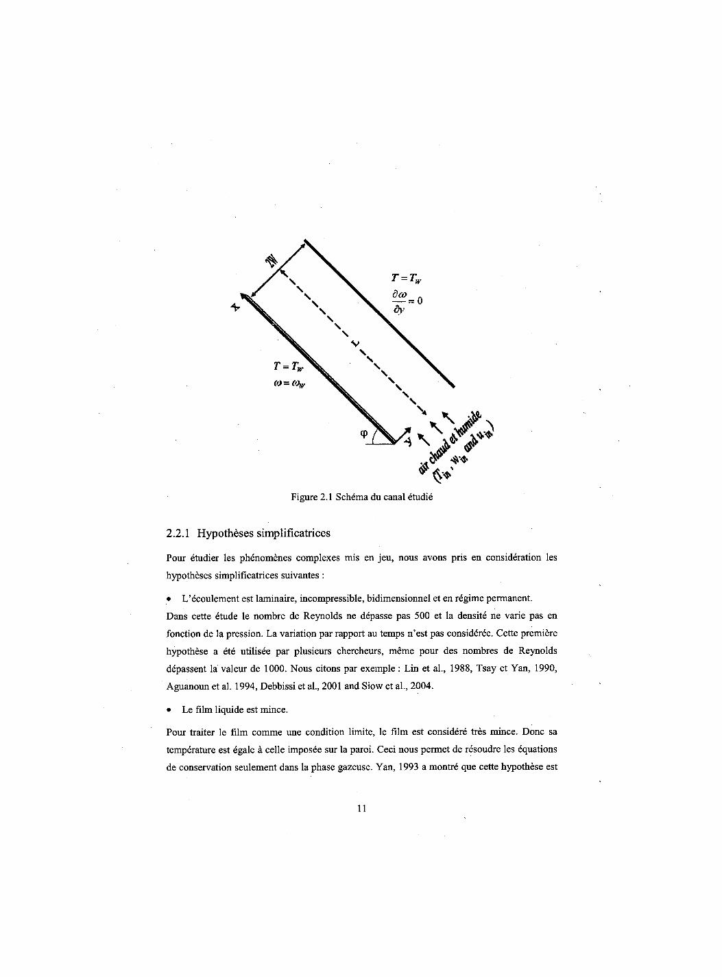
Figure 2.1 Schema du canal etudie 11
Figure 2.2 Schema d'un volume de controle principale 21
Figure 2.3 Schema du maillage 22
Figure 2.4 Evolution de la temperature moyenne 25
Figure 2.5 Evolution du nombre de Nusselt 25
Figure 2.6 Evolution du nombre de Nusselt moyen 27
Figure 2.7 Evolution du nombre de Nusselt latent 28
Figure 2.8 Evolution du nombre de Nusselt sensible 29
Figure 2.9 Evolution axiale de la temperature du film 30
Figure 3.1 Schematic representation of the physical system 37
Figure 3.2 Streamlines, isotherms and isoconcentration lines 42
Figure 3.3 Axial velocity profiles 44
Figure 3.4 Axial velocity distribution near the plates 44
Figure 3.5 Axial evolution of the friction factor 45
Figure 3.6 Axial evolution of the average mass fraction 46
Figure 3.7 Axial evolution of the average temperature 47
Figure 3.8 Axial evolution of sensible Nusselt number 48
Figure 3.9 Axial evolution of Sherwood number 49
Figure 3.10 Axial evolution of latent Nusselt number 50
Figure 3.11 Axial evolution of dimensionless mass fraction gradient near the walls 51
Figure 3.12 Axial evolution of latent Nusselt to sensible Nusselt numbers ratio 52
Figure 4.1 Schematic representation of the physical system 59
Figure 4.2 Comparison between our results and those from Laaroussi et al., 2009 64
Figure 4.3 Axial velocity profiles at X = 4.62 67
Figure 4.4 Evolution of the axial velocity near walls 68
Figure 4.5 Streamlines 69
Figure 4.6 Axial evolution of the friction factor 71
Figure 4.7 Dimensionless profiles for Case #3 73
Figure 4.8 Axial evolution of the dimensionless transverse vapour velocity at the walls 75
v
Figure 4.9 Axial evolution of the dimensionless mass fraction gradient close to the plate for
Case #3 ; 76
Figure 4.10 Axial evolution of Sherwood number 77
Figure 4.11 Axial evolution of latent Nusselt number 79
Figure 4.12 Axial evolution of dimensionless bulk temperature for case #3 ; 80
Figure 4.13 Axial evolution of the latent to the sensible Nusselt numbers ratio 81
Figure 4.14 Flow reversal chart 84
Figure 5.1 Schematic representation of the physical system 90
Figure 5.2 Comparison between our results and those from literature 94
Figure 5.3 Axial evolution of the friction factor 97
Figure 5.4 Axial velocity profiles at X = 4.86 98
Figure 5.5 Axial velocity profiles 99
Figure 5.6 Streamlines for different inclination angles 100
Figure 5.7 Axial evolution of the dimensionless vapour velocity at the upper wall 101
Figure 5.8 Dimensionless mass fraction and temperature profiles (2D) 103
Figure 5.9 Dimensionless temperature profiles (3D) 104
Figure 5.10 Dimensionless mass fraction profiles... 106
Figure 5.11 Mean dimensionless temperature 107
Figure 5.12 Axial evolution of Sherwood number at the lower wet plate 108
Figure 5.13 Axial evolution of the sensible Nusselt number 109
Figure 5.14 Axial evolution of latent Nusselt number 110
Figure 5.15 Flow reversal chart I l l
vi
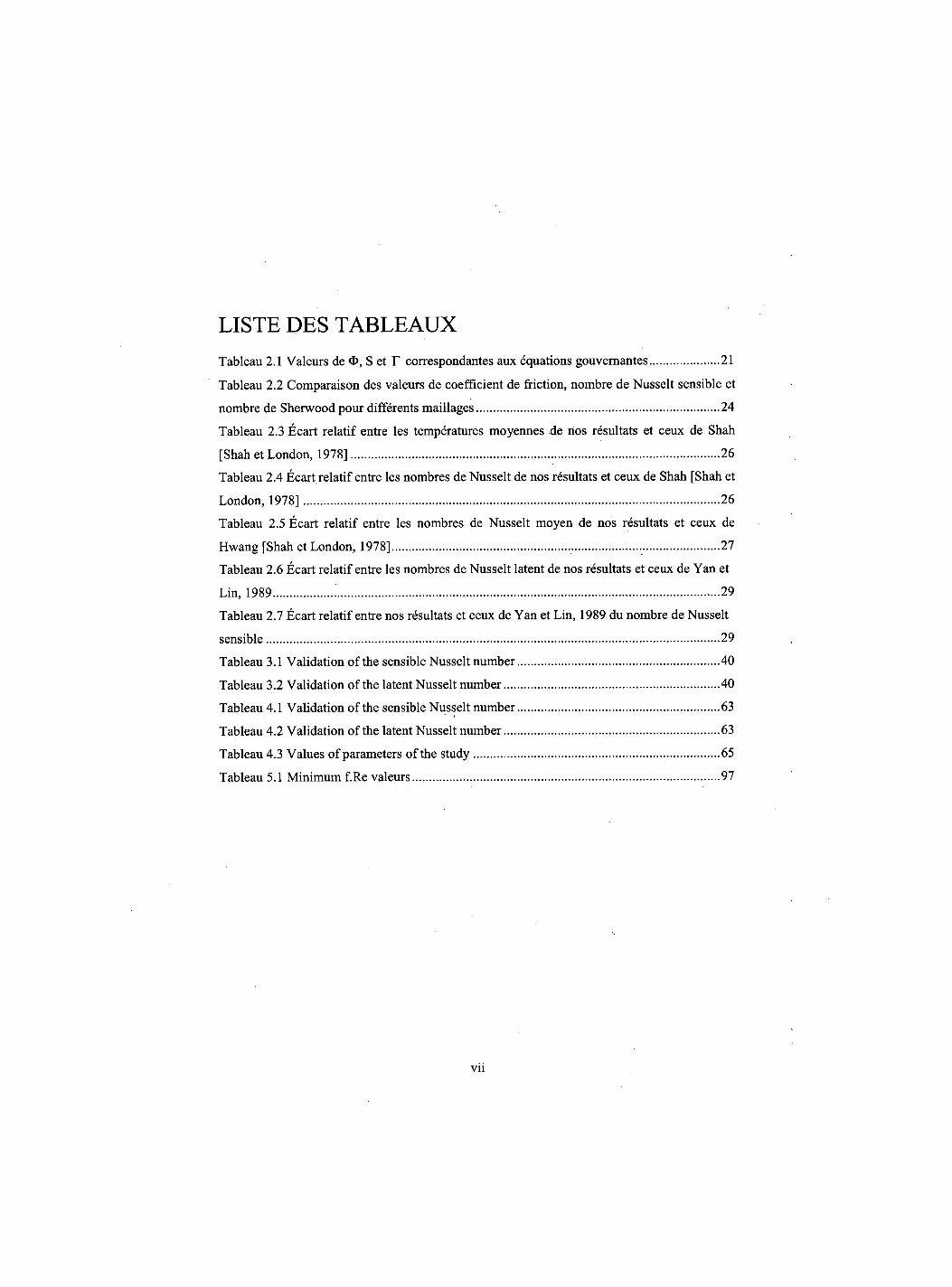
LISTE DES TABLEAUX Tableau 2.1 Valeurs de O, S et r correspondantes aux equations gouvernantes 21
Tableau 2.2 Comparaison des valeurs de coefficient de friction, nombre de Nusselt sensible et
nombre de Sherwood pour differents maillages 24
Tableau 2.3 Ecart relatif entre les temperatures moyennes de nos resultats et ceux de Shah
[Shah et London, 1978] 26
Tableau 2.4 Ecart relatif entre les nombres de Nusselt de nos resultats et ceux de Shah [Shah et
London, 1978] 26
Tableau 2.5 Ecart relatif entre les nombres de Nusselt moyen de nos resultats et ceux de
Hwang [Shah et London, 1978] 27
Tableau 2.6 Ecart relatif entre les nombres de Nusselt latent de nos resultats et ceux de Yan et
Lin, 1989 29
Tableau 2.7 Ecart relatif entre nos resultats et ceux de Yan et Lin, 1989 du nombre de Nusselt
sensible 29
Tableau 3.1 Validation of the sensible Nusselt number 40
Tableau 3.2 Validation of the latent Nusselt number 40
Tableau 4.1 Validation of the sensible Nusselt number 63
Tableau 4.2 Validation of the latent Nusselt number 63
Tableau 4.3 Values of parameters of the study 65
Tableau 5.1 Minimum f.Re valeurs 97
vii
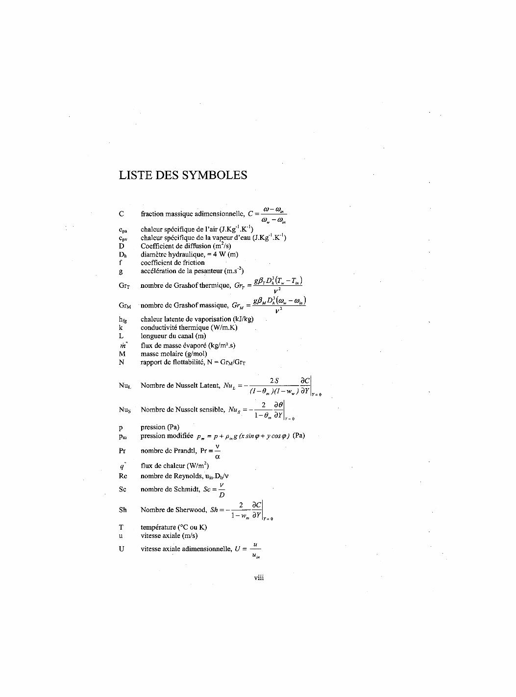
LISTE DES SYMBOLES
^ . .. _ CO — Q),n C fraction massique adimensionnelle, C = —
cpa chaleur specifique de l'air (J-Kg^.K"1) cpv chaleur specifique de la vapeur d'eau (J.Kg1 .K"1) D Coefficient de diffusion (m2/s) Dh diametre hydraulique, = 4 W (m) f coefficient de friction g acceleration de la pesanteur (m.s 2)
GrT nombre de Grashof thermique, GrT = ^ ~ T"> ) v
GrM nombre de Grashof massique, GrM = g f t f 0 * fa-~ ) v
hfg chaleur latente de vaporisation (kJ/kg) k conductivity thermique (W/m.K) L longueur du canal (m) m flux de masse evapore (kg/m2.s) M masse molaire (g/mol) N rapport de flottabilite, N = GrM/GrT
NuL Nombre de Nusselt Latent, NuL = -
Nus Nombre de Nusselt sensible, Nus = -
2 S dC (l-Om)(l-ww)dY
2 d0
Y= 0
Y= 0 1-0. dY
p pression (Pa) pm pression modifiee pm = p + pin g (x sin <p + y cos (p) (Pa)
v Pr nombre de Prandtl, Pr = —
a q flux de chaleur (W/m2) Re nombre de Reynolds, Uj„.Dh/v
v Sc nombre de Schmidt, Sc = —
D
Sh Nombre de Sherwood, Sh = -2 dC
l-wm dY
T temperature (°C ou K) u vitesse axiale (m/s)
u U vitesse axiale adimensionnelle, U =
u •
r = o
viii
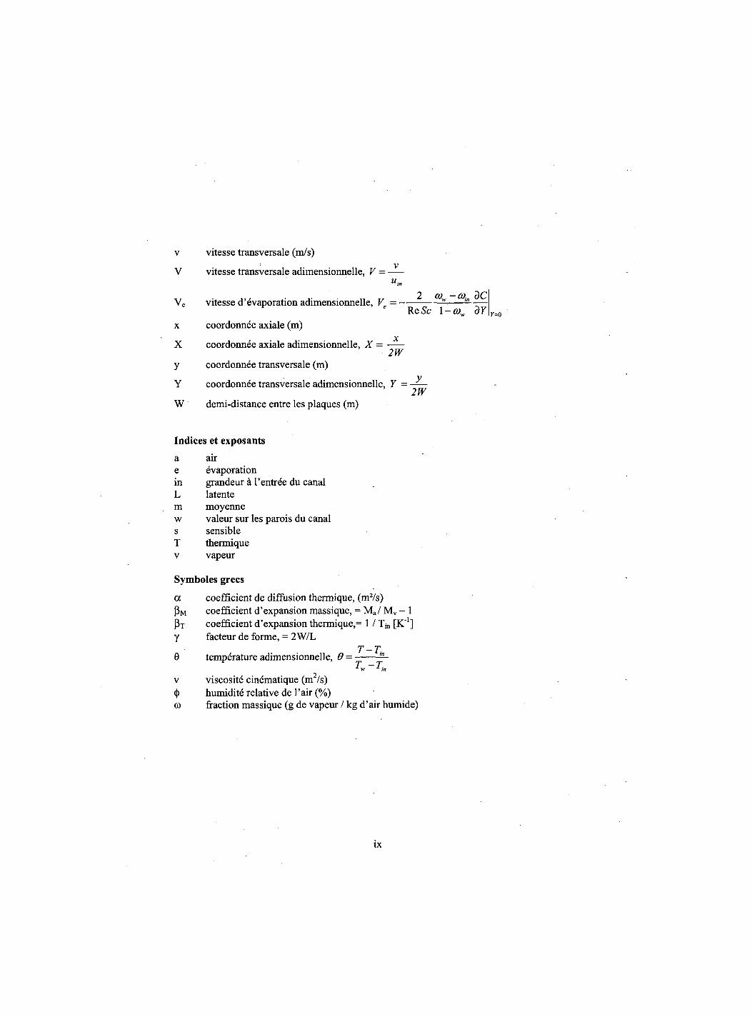
v vitesse transversale (m/s) v V vitesse transversale adimensionnelle, V =
Uin
Ve vitesse d'evaporation adimensionnelle, V. = ———(°m ^ ReSc 1 -cow dY
x coordonnee axiale (m) x X coordonnee axiale adimensionnelle, X =
2W y coordonnee transversale (m)
y
y=o
Y coordonnee transversale adimensionnelle, Y = 2W
W demi-distance entre les plaques (m)
Indices et exposants a air e evaporation in grandeur a 1'entree du canal L latente m moyenne w valeur sur les parois du canal s sensible T thermique v vapeur
Symboles grecs
a coefficient de diffusion thermique, (m2/s) Pm coefficient d'expansion massique, = Ma/ Mv - 1 Pt coefficient d'expansion thermique,= 1 / Tin [K"1] y facteur de forme, = 2W/L
T-T 0 temperature adimensionnelle, 9 -
T - T
<|>_ humidite relative de l'air (%) co fraction massique (g de vapeur / kg d'air humide)
v viscosite cinematique (m /s)
ix
CHAPITRE 1 Introduction generate et revue bibliographique
1.1 Introduction
Les phenomenes de transfert de chaleur et de masse sont d'un interet considerable dans le
domaine d'ingenierie. Cet interet se traduit par de nombreuses applications comme le
dessalement d'eau de mer, la distillation, la climatisation, le sechage du bois, le
refroidissement des composantes electroniques,...
L'augmentation des besoins en eau douce causee par les diverses utilisations comme dans
l'industrie et l'irrigation, ainsi que les ressources qui restent invariantes ou meme en
diminution, entrainent la necessite de creer et developper des unites de dessalement surtout
dans les regions qui souffrent d'un deficit en eau douce. Les precedes de dessalement sont
multiples (Osmose inverse, Electrodialyse, Evapo-condensation...). Le precede d'evapo-
condensation, qui est un precede thermique, est interessant pour les petites unites de
dessalement. Ce precede consiste a utiliser un courant d'air chaud pour evaporer l'eau a
dessaler pour ensuite condenser la vapeur d'eau resultante.
Dans le present travail nous etudions un probleme ayant une relation directe avec ces
applications faisant intervenir les phenomenes de transferts de chaleur et de masse dans un
canal vertical. Celui-ci est constitue de deux plaques planes paralleles avec un film en
evaporation et/ou condensation. Pour comprendre ces phenomenes, nous presentons dans le
premier chapitre une revue des travaux anterieurs, ce qui nous aidera a situer notre etude.
Nous insistons plus particulierement sur les etudes consacrees au phenomene de renversement
d'ecoulement. Dans le deuxieme chapitre nous presentons en detail le modele mathematique
ainsi que la methode des volumes finis utilisee dans ce travail et le code numerique qui a ete
developpe. Les resultats obtenus par ce code sont compares avec des travaux de litterature afin
d'assurer sa validite.
Le troisieme chapitre traite des effets combines des forces d'Archimede d'origine thermique et
massique sur la convection laminaire dans un canal symetrique isotherme vertical. Le
renversement d'ecoulement qui resulte de ces effets, fait l'objet du quatrieme chapitre. Les
1
conditions d'existence de ce phenomene y sont presentees dans des abaques et par des
expressions analytiques. Dans le cinquieme chapitre nous etudions le renversement
d'ecoulement laminaire dans un canal asymetrique isotherme incline. Le but est tant de
determiner les conditions d'existence de ce renversement en fonction de l'inclinaison du canal.
1.2 Convection forcee
L'evaporation par convection forcee d'un film au-dessus d'une plaque plane avec un transfert
combing de chaleur et de masse a fait l'objet de plusieurs recherches theoriques et
experimentales. Par exemple Ait Aldjet, 1988 a fait une etude theorique et experimentale des
transferts ayant lieu au niveau des parois humides et adiabatiques d'un canal plan a l'interieur
duquel circule un ecoulement force d'air. L'effet de certains parametres de geometrie et
d'entree sur 1'amelioration des echanges thermique et massique a ete etudie. Les longueurs
d'etablissement thermique et massique ont ete egalement determinees. Lin et al., 1992 ont
etudie les effets combines des forces d'Archimede d'origines thermique et massique sur la
convection laminaire forcee dans un canal horizontal a section carree. La paroi inferieure est
maintenue humide et soumise a un flux de chaleur uniforme et les autres parois sont seches et
adiabatiques. Ces auteurs ont montre numeriquement que le transfert de chaleur est domine
essentiellement par le transport de chaleur latente.
Boukadida, 2000 a analyse les transferts couples de chaleur et de masse par convection forcee
dans un canal horizontal. Le phenomene d'evaporation de l'eau a ete etudie dans un
ecoulement d'air sec, d'air humide et de vapeur surchauffee. II a montre que l'analogie entre
le transfert de chaleur et de masse n'est valable que pour les faibles temperatures et pour de
faibles concentrations ou le transfert de chaleur par rayonnement est negligeable et que la
temperature d'inversion augmente avec la vitesse de l'ecoulement a l'entree.
Yan et Soong, 1995 ont etudie le probleme d'evaporation d'un film liquide ruisselant sur une
plaque plane inclinee et soumise a un flux de chaleur uniforme et constant. lis ont suppose que
les ecoulements d'air et du film liquide sont turbulents et sans ondes. Leurs resultats montrent
que l'augmentation de Tangle d'inclinaison, de l'epaisseur du film liquide a l'entree oil de la
vitesse du courant d'air entrainent une reduction des temperatures de la plaque et de
l'interface. Mezaache et Daguenet, 2000 ont etudie numeriquement 1'evaporation, dans un
2
courant force d'air humide, d'un film mince d'eau ruisselant sur une plaque plane inclinee,
consideree adiabatique ou traversee par un flux de chaleur constant. lis ont montre que le
terme de diffusion enthalpique est negligeable et que le transfert de chaleur est domine par le
transfert lie a la transition liquide-vapeur.
1.3 Convection naturelle avec transfert de chaleur et de masse
La convection naturelle d'origines thermique et massique le long d'une plaque verticale ou
inclinee a fait l'objet de plusieurs etudes. Parmi ces etudes on peut citer celle de Bolter et al.,
1946 qui ont realise une etude experimentale par convection naturelle a partir d'un plan libre
d'eau. La quantite d'eau evaporee en fonction de 1'humidite de I'air exterieur a ete etudiee.
Maters et al., 1957 et Gill et al., 1965 ont developpe des methodes analytiques pour la
resolution du probleme des transferts de chaleur et de masse, pour des conditions aux limites
de temperature et de concentration imposees et en 1'absence de film ruisselant. La solution
analytique a ete determinee par d'autres chercheurs en supposant que le rapport des forces
volumiques (N = (5M (C - Cin)/ fiT (T - Tin)) est constant.
Une etude theorique et experimentale de 1'evaporation par convection naturelle sur une plaque
plane poreuse et saturee d'eau a ete effectuee par Vachon, 1979. Cet auteur a utilise deux
methodes de calcul dont la premiere est analytique et basee sur les solutions affines et la
deuxieme numerique utilisant la methode des differences finies. Les resultats obtenus par ces
deux methodes sont compares a ceux experimentales. De plus l'auteur a etabli des correlations
donnant les nombres de Nusselt et Sherwood ainsi que le debit evapore en fonction du nombre
de Grashof combine. Ben Nasrallah et Arnaud, 1985 ont etudie theoriquement l'evaporation
en convection naturelle sur une plaque verticale humide chauffee a densite de flux variable
suivant la hauteur. Deux types de methodes ont ete utilises pour resoudre le systeme
d'equations : methode semi-analytique pour rechercher des solutions affines et des solutions
quasi-affines et une methode de differences finies. Leurs resultats montrent que la methode
quasi-affine est moins restrictive et donne une meilleure approximation de la solution exacte.
Ainsi, ils ont represente des expressions approchees pratiques de la temperature et de la
concentration parietale et des nombres de Nusselt et de Sherwood locaux.
3
Tsay et al., 1990 ont etudie l'evaporation par convection naturelle d'un film liquide s'ecoulant
sur une plaque verticale adiabatique. Cette etude a montre que le transfert de chaleur se fait
principalement par le transport de chaleur latente. Une etude sur le transfert de chaleur et de
masse en convection naturelle entre deux plaques paralleles et verticales avec un film d'eau ou
d'ethanol en evaporation a ete menee par Yan et Lin, 1990. Leurs resultats montrent que
l'hypothese d'un film mince n'est valable que pour de faibles debits massiques.
Debbissi, 2000 a etudie l'evaporation de l'eau par convection naturelle entre deux plaques
planes dont l'une est humide et soumise a un flux de chaleur uniforme alors que l'autre est
supposee impermeable et maintenue isotherme ou chauffee a flux constant. Le rayonnement
des plaques a ete pris en consideration. Leurs resultats montrent que le transfert de chaleur est
domine par le transport de chaleur latente meme si le rayonnement des plaques est important
et que la temperature de l'air a cote des plaques subit un abaissement important cause par
l'evaporation du film liquide.
Les effets combines des forces d'Archimede de diffusion thermique et massique dans un
ecoulement en convection naturelle laminaire a l'interieur des conduites verticales ont ete
etudies par Yan et Lin, 2001. Ces auteurs se sont interesses aux effets de la temperature des
parois mouillees, de l'humidite de l'air a l'entree et du facteur de forme sur 1'ecoulement et le
transfert de chaleur et de masse. lis affirment que le transfert de chaleur se fait essentiellement
par le transport de chaleur latente soit en evaporation ou en condensation.
Une etude experimentale de l'evaporation par convection naturelle d'un mince film d'eau
ruisselant sur les parois internes d'un canal vertical et soumises a une densite de flux constante
a ete menee par Cherif et al., 2005. lis ont etudie l'effet de la densite de chauffage sur la
temperature du film et sur le coefficient d'echange massique. Leurs resultats montrent qu'une
augmentation de la densite du flux de chauffage augmente la temperature du film et que cette
temperature presente deux zones : une zone d'echauffement vers la sortie du canal et une zone
d'evaporation a mi-hauteur de ce dernier. D'autre part, ils ont montre que le profil de
temperature a mi-hauteur du canal presente le phenomene de stratification pres de ses parois.
4
1.4 Convection mixte avec transfert couple de chaleur et de masse
De nombreuses etudes ont ete consacrees ces dernieres annees aux effets combines des forces
d'Archimede thermique et massique sur les ecoulements en convection mixte ou naturelle. Lin
et al., 1988 ont etudie la convection mixte laminaire dans un tube vertical. Leurs resultats
montrent que 1'effet des forces d'Archimede est important pour des faibles nombres de
Reynolds et des temperatures d'entree elevees et que le transfert de chaleur est domine par le
transport de chaleur latente due a 1'evaporation du film liquide. Yan et al., 1991 ont etudie
1'effet du film liquide sur le transfert de chaleur et de masse par convection laminaire dans un
canal vertical. Le canal est forme par deux plaques paralleles et adiabatiques sur lesquelles
ruisselle un film liquide de temperature superieure a celle de l'air a l'entree du canal.
L'ecoulement est descendant. Les resultats obtenus montrent que le rapport entre les chaleurs
latente et sensible transferees est plus important pour des faibles debits d'ecoulement et des
temperatures elevees du film. Une etude numerique du transfert combine de chaleur et de
masse dans un canal vertical a ete menee par Lee et al., 1997. Le canal est rectangulaire et une
de ses parois est poreuse et maintenue constamment humide par un film d'eau liquide, les
autres parois sont seches et isolees. Ces auteurs ont constate que du fait de 1'evaporation du
film liquide, le transfert de masse favorise le transfert de chaleur. Yan, 1998 a mene une etude
sur le transfert de chaleur et de masse en convection mixte laminaire dans une conduite
rectangulaire en rotation et en presence d'un film d'eau en evaporation. La conduite a des
parois poreuses, isothermes et humides. L'auteur a constate que le transfert de chaleur le long
des parois poreuses est domine par le transport de chaleur latente et que la rotation favorise le
transfert de chaleur et de masse et augmente le facteur de friction local. Le meme auteur a
traite numeriquement en 1999 le refroidissement evaporatif d'un film liquide par la convection
mixte en regime turbulent dans un canal vertical. Le canal est forme par deux plaques planes
supposees adiabatiques, sur lesquelles ruisselle un film liquide. L'ecoulement est descendant.
Ses resultats montrent que le transfert de chaleur est domine par le transport de chaleur latente
liee a 1'evaporation du film liquide et que le refroidissement est maximal pour des valeurs
elevees de temperature d'entree.
Ait Hammou et al., 2004 ont traite les effets des transferts simultanes de chaleur et de masse
en ecoulement laminaire descendant d'air humide dans un canal vertical avec des parois
5
humides. Ces auteurs ont etudie les effets de la temperature et de l'humidite de l'air a l'entree
sur son ecoulement le long du canal et sur le transfert de chaleur et de masse. lis ont trouve
que le facteur de friction et le nombre de Sherwood augmentent avec ces deux facteurs. D'un
autre cote, ils ont montre que les forces d'Archimede influencent beaucoup le profil de vitesse
axiale, le facteur de friction et les nombres de Sherwood et Nusselt.
Huang et al., 2005 ont analyse numeriquement le transfert de chaleur et de masse en
convection mixte laminaire dans un canal vertical de section rectangulaire avec film en
evaporation et condensation. Le canal est forme de quatre parois dont deux solides et isoles,
alors que les deux autres sont poreuses et maintenues a des temperatures constantes. Les
proprietes physiques sont considerees constantes. La resolution numerique est faite par la
methode de vorticite-vitesse pour un ecoulement parabolique tridimensionnelle. Leurs
resultats montrent que pour de grandes valeurs de temperature, il resulte une diminution du
coefficient de friction. Le transfert de masse et de chaleur augmente avec le rapport de forme
de la section rectangulaire, ainsi qu'une augmentation de l'humidite entraine une diminution
du transfert de chaleur.
Dans les deux sections qui suivent nous citons quelques etudes qui traitent le renversement de
l'ecoulement dans des conduites verticales et inclinees.
1.5 Renversement d'ecoulement dans un canal vertical
La convection mixte thermique avec renversement d'ecoulement dans la region d'entree dans
des tubes horizontal et vertical a ete etudiee numeriquement par Wang et al., 1994. La
methode de resolution utilisee est celle des differences finies pour un modele 3D. Les resultats
obtenus montrent que la conduction axiale et la convection mixte peuvent creer des distorsions
sur la temperature et la vitesse. Ces distorsions prennent de 1'importance si on augmente le
nombre de Prandtl et/ou le nombre de Rayleigh. La contrainte de cisaillement sur les parois
admet un optimum dans la position ou les distorsions se produisent. Cet optimum est soit un
maximum pour le cas de chauffage, soit un minimum dans le cas de refroidissement. Le
regime du reversement d'ecoulement est identifie dans les coordonnees Peclet-Rayleigh.
Nguyen et al., 2004 ont etudie numeriquement l'instabilite et le renversement d'un ecoulement
laminaire en convection thermique mixte dans un tube vertical. La resolution numerique basee
6
sur la methode des volumes finis a ete utilisee. Les resultats montrent que le renversement de
l'ecoulement depend essentiellement du nombre de Grashof. Ainsi pour le cas ou les forces
d'Archimede sont opposees a l'ecoulement, le renversement a lieu pres des parois pour un
nombre critique de Grashof de 3.105 alors qu'il prend lieu au centre du tube pour un nombre
critique de 106 dans le cas ou les forces d'Archimede agissent dans le meme sens.
Une solution analytique pour un ecoulement developpe en convection mixte avec transfert de
chaleur et de masse sans changement de phase entre deux plaques paralleles plane a ete menee
par Boulama et Galanis, 2004. lis considerent deux conditions sur les plaques (une
temperature uniforme, UWT ou un flux de chauffage uniforme, UHF) alors que la
concentration est supposee uniforme. Leurs resultats montrent que la solution pour le cas
UWT depend du parametre (Gtj + GtM) / Re alors qu'elle depend de trois parametres
independants : Gtx / Re, GtM / Re et qi / q2- Ainsi, les conditions produisant le renversement de
l'ecoulement sont analysees. Salah El-Din, 1992 a analyse 1'effet des forces de flottabilite
d'origine thermique et massique sur la convection forcee en ecoulement laminaire developpe
dans un canal vertical. Les parois du canal sont soumises a des temperatures et concentrations
constantes et superieures a celles a l'entree. Ses resultats ont montre que le renversement
d'ecoulement ne peut avoir lieu que dans le cas ou les temperatures et les concentrations
imposees sur les parois soient asymetriques. Ainsi, les conditions d'existence du renversement
ont ete representees.
Recemment, Laaroussi et al., 2009 ont mene une etude numerique de la convection mixte
laminaire dans un canal vertical constitue de deux plaques planes paralleles sur lesquelles
ruisselle un film liquide. Les plaques sont maintenues a une temperature constante et le film
liquide est suppose d'epaisseur negligeable. L'ecoulement d'air est descendant et le film liquide
est soit de l'eau soit de l'hexane. Les auteurs ont particulierement compare les resultats obtenus
avec un modele mathematique avec proprietes constantes (modele de Boussinesq) et ceux
obtenus en considerant des proprietes variables. lis ont conclu que le premier modele n'est
valable que pour des temperatures et des concentrations assez faibles. De plus, pour
uniquement de la diffusion de la masse, la force d'Archimede cause 1'acceleration de
l'ecoulement dans la couche limite et du renversement de ce dernier au centre du canal.
7
Plus recemment, Desrayaud et Lauriat, 2009 ont etudie numeriquement le renversement
d'ecoulement laminaire en convection thermique mixte dans canal vertical. Ce canal est forme
de deux plaques planes paralleles soumises a une temperature uniforme. L'approximation de
Boussinesq a ete adoptee et le modele numerique est base sur l'algorithme SIMPLE. Les
resultats obtenus montrent que dans le cas des forces de gravite aidante, le renversement
d'ecoulement se produit au centre du canal pres de l'entree (soit x/(Dh Re)|crit. ~ 0.007). De
plus les auteurs ont remarque que la longueur du canal n'a pas d'effet sur la forme et la taille
des cellules de renversement tant que le canal est suffisamment long (L/2b >10.)
1.6 Renversement d'ecoulement dans un canal incline
Les phenomenes de transferts couples de chaleur et de masse ont ete abondamment etudies
dans des conduites horizontales ou verticales alors que pour des conduites inclinees, ces etudes
sont moins traitees. Ainsi les effets des conditions d'entree sur l'evaporation d'un film sur une
plaque inclinee ont ete traites par Mezaache et Daguenet, 2005. Le calcul numerique utilise est
base sur la methode implicite des differences finies. Les resultats obtenus montrent que pour
un flux de chaleur impose ou une temperature imposee, l'effet de l'inclinaison devient plus
important pour les grandes valeurs de la vitesse du gaz et aussi lorsqu'on augmente le debit
d'ecoulement du liquide. Aussi les auteurs ont montre que dans l'intervalle d'inclinaison 0-
10°, l'augmentation de Tangle d'inclinaison implique un accroissement du taux de masse
evaporee du film. Le transfert de chaleur par convection mixte associe a l'evaporation d'un
film liquide dans une conduite carree inclinee a ete etudie numeriquement par Jang et al.,
2005. Leurs resultats montrent que le facteur de friction et les transferts de chaleur et de masse
sont considerablement affectes par Tangle d'inclinaison. Said et al., 2005 ont etudie
numeriquement la convection thermique naturelle en regime turbulent dans un canal forme de
deux plaques planes isothermes et inclinees. Leurs resultats montrent que le nombre de
Nusselt subit une diminution quand le nombre de Rayleigh augmente. Les auteurs ont etabli
une correlation pour le calcul du nombre de Nusselt en fonction du nombre de Rayleigh et de
l'inclinaison du canal. Guimaraes et Menon, 2004 ont etudie le transfert de chaleur par
convection mixte dans un canal rectangulaire incline avec trois sources de chaleur sur sa paroi
inferieure. La paroi superieure est maintenue a une temperature froide fixe. Les auteurs
affirment que Tangle d'inclinaison a un grand effet sur l'ecoulement et le transfert de chaleur
8
pour de faibles nombres de Reynolds, surtout pour des valeurs d'angle d'inclinaison entre 0°
et 45°. La recirculation et le renversement d'ecoulement sont presentes pour quelques
situations telles que Re = 10 et des angles d'inclinaison de 45° et 90°.
Rheault et Bilgen, 1993 ont etudie numeriquement la convection thermique mixte laminaire
dans un canal incline avec des conditions asymetriques de chauffage. Les equations
regissantes qui sont elliptiques ont ete discretisees par la methode des volumes finis et en
utilisant la formulation vorticite-ligne de courant. Les auteurs ont montre que le renversement
d'ecoulement peut avoir lieu pour des nombres de Peclet variant de 10 a 150, ou 1'effet de la
diffusion axiale devient critique. Ainsi les resultats montrent que le renversement pres de la
paroi froide et/ou au centre du canal devient plus accentue pour de larges valeurs de Gr/Re2 et
que le transfert de chaleur croit generalement avec 1'augmentation de Gr/Re2 et de Tangle
d'inclinaison.
1.7 Conclusion
Dans ce chapitre, nous avons presente une revue de litterature des differents travaux traitant
des transferts de chaleur et de masse, et plus particulierement ceux qui traitent la convection
mixte avec changement de phase. Vue la complexity de ces phenomenes, il apparait que la
plupart des travaux numeriques adoptent des hypotheses simplificatrices qui limitent le
domaine de validite des modeles utilises et des resultats obtenus et de ce fait ne permettent pas
l'etude des certains phenomenes physiques. En Particulier, la diffusion axiale de la quantite de
mouvement, de l'energie et des especes est souvent negligee. Ce qui conduit a des modules
paraboliques. Le phenomene de renversement d'ecoulement dans les conduites en
developpement simultane avec transfert de chaleur et de masse accompagne d'un changement
de phase est tres peu etudie. Dans ce travail, nous adoptons un modele qui prend en
consideration la diffusion axiale (modele elliptique) pour etudier le renversement
d'ecoulement. Nous nous proposons, ainsi, d'approfondir l'etude ce phenomene, ses effets sur
les transferts et le champ hydrodynamique ainsi que les conditions de son existence.
9
CHAPITRE 2 Moderation numerique
mathematique et
2.1 Introduction
Pour atteindre les objectifs vises, il est necessaire de definir une methodologie bien appropriee
afin d'etablir un programme numerique valide qui permet de simuler tous les phenomenes mis
en jeu. Nous presentons dans cette partie la formulation mathematique generale du probleme
etudie (canal asymetrique incline). Ainsi, la formulation mathematique pour le cas du canal
vertical sera ensuite deduite de celle du canal incline. La methode de resolution utilisee est
decrite en detail. Le code de calcul elabore est teste par comparaison de nos resultats avec
ceux de la litterature.
2.2 Description et modelisation mathematique du probleme etudie
Le modele physique etudie est un canal vertical forme de deux plaques planes, paralleles, et
distantes de 2W. Les plaques sont maintenues a une temperature constante et uniforme (Tw).
L'une de ces plaques (ou juste celle du bas, dans le cas d'un canal incline) sont mouillees par
un film d'eau de faible epaisseur. Vu que le film ne peut tenir sur la plaque du haut dans le cas
du canal incline, la plaque du haut est maintenue impermeable. Le canal est traverse par un
ecoulement ascendant laminaire d'air humide chaud en regime permanent. A l'entree, ce
dernier a une temperature Tjn, une humidite relative (J)jn et un profil de vitesse uniforme uin
(Figure 2.1).
10
2.2.1 Hypotheses simplificatrices
Pour etudier les phenomenes complexes mis en jeu, nous avons pris en consideration les
hypotheses simplificatrices suivantes :
• L'ecoulement est laminaire, incompressible, bidimensionnel et en regime permanent.
Dans cette etude le nombre de Reynolds ne depasse pas 500 et la densite ne varie pas en
fonction de la pression. La variation par rapport au temps n'est pas consideree. Cette premiere
hypothese a ete utilisee par plusieurs chercheurs, meme pour des nombres de Reynolds
depassent la valeur de 1000. Nous citons par exemple : Lin et al., 1988, Tsay et Yan, 1990,
Aguanoun et al. 1994, Debbissi et al., 2001 and Siow et al., 2004.
• Le film liquide est mince.
Pour traiter le film comme une condition limite, le film est considere tres mince. Done sa
temperature est egale a celle imposee sur la paroi. Ceci nous permet de resoudre les equations
de conservation seulement dans la phase gazeuse. Yan, 1993 a montre que cette hypothese est
11
valide pour des faible debits de liquide. Cette hypothese a ete largement utilisee dans la
litterature [Gebhart et Pera, 1971, Lin et al., 1988, Debbissi et al., 2003 et Laaroussi et al., 2009].
• L'air humide est considere gaz parfait.
Sous la pression atmospherique, l'air humide peut etre considere comme melange de deux gaz
parfaits. Sa densite est determinee a l'aide de la loi des gaz parfait et la pression totale est la
somme des pressions partielles des deux gaz [Mezaache et Daguenet, 2005 et Siow et al.,
2007],
• La dissipation visqueuse et le travail des forces de pression sont negliges.
La diffusion d'energie d'origine purement mecanique est negligee du fait que la vitesse et la
viscosity de l'air sont faibles. Cette hypothese a 6te prise en consideration par Tsay et Yan,
1990, Ali Cherif et Daif, 1999 et Debbissi et al. 2001.
• L'interface liquide-vapeur est en equilibre thermodynamique.
Cette hypothese a ete prise en consideration du fait que le changement de phase ne se produit
que sous des conditions de saturation. Done, l'interface est consideree saturee a la temperature
Tw. Plusieurs auteurs ont pris en consideration cette hypothese [Tsay et Yan, 1990, Yan et
Soong, 1995 et Siow et al., 2007],
• Les effets Soret et Dufour sont negligeables.
Le flux de masse cause par le gradient de temperature (effet Soret) ainsi que le flux de chaleur
cause par le gradient de masse sont consideres negligeables. Ces effets secondaires ne sont pas
tenus en compte car les gradients de temperature et concentration sont faibles [Gebhart et
Pera, 1971, Tsay et Yan, 1990, Aguanoun et al. 1994 et Ali Cherif et Daif, 1999].
• Le transfert par rayonnement est negligeable.
Du fait que l'intervalle de temperature considere reste faible, 1'effet radiatif des parois peut
etre considere negligeable [Gebhart et Pera, 1971, Agunaoun et al., 1996, Debbissi, 2000,
Mezaache et Daguenet, 2005],
• L'approximation de Boussinesq est adoptee.
Pour tenir compte des effets de flottabilite, et vu que les equations gouvernantes competes et
exactes ne sont pas resolvables analytiquement, certaines approximations sont demandees. La
12
plus simple approximation est celle de Boussinesq. Cette approximation est fondee sur
l'hypothese de considerer la densite comme constante sauf dans le terme de flottabilite
[Boussinesq, 1903]. Elle fournit un modele tres utilise, confirme par une litterature abondante
rapportant d'excellents accords entre calculs et experiences.
La validite de cette approximation a fait l'objet de plusieurs etudes. Gray et Giorgini, 1976 ont
presente une nouvelle methode d'obtention des equations approchees des ecoulements en
convection naturelle en prenant des proprietes physiques variables en fonction de la
temperature et de la pression. Les auteurs montrent que cette approximation est bien valide
pour des faibles differences de temperature et de concentration. Cette methode a ete appliquee
a l'eau et a l'air a temperature ambiante. Shang et Wang (1993) ont etudie la deviation dans
les calcules de transfert de chaleur en raison d'ignorer la variability des proprietes physiques.
Leurs resultats montrent que l'approximation de Boussinesq n'est valable que si les gradients
de temperature restent faibles. Cette approximation a ete abondamment adoptee [Gebhart et
al., 1988, Tsay et Yan, 1990, Ait Hammou et al. 2004 et Laaroussi et al., 2009].
Cette approximation est exprimee par la relation suivante
p = pin[^-PriT-Tin)-PM{(0-(0in)} (2.1)
—1 fdo^\ avec : = — — : Coefficient d'expansion volumique du a la temperature. Pi,
et
dT y C =cste,p=cste
—\(Bo^ PM = — : Coefficient d'expansion volumique du a la concentration. Pin )T=cs,e p=cste
PM D'apres la loi des gaz parfaits : p = (P: pression total du melange et M sa masse molaire)
R T
Done on peut facilement demontrer que : fiT = —
n • R - 1 P (dM) On a aussi: p M = — = — . —— Pin \OCOjT=csl^p=csle pin RT\dO})T=csle,p=cs,e
La loi de dalton nous permet d'ecrire P = Pv+Pa
_ ... . , . , . . „ RT m En utilisant la loi des gaz parfaits on a : P = .— 6 F V M
13
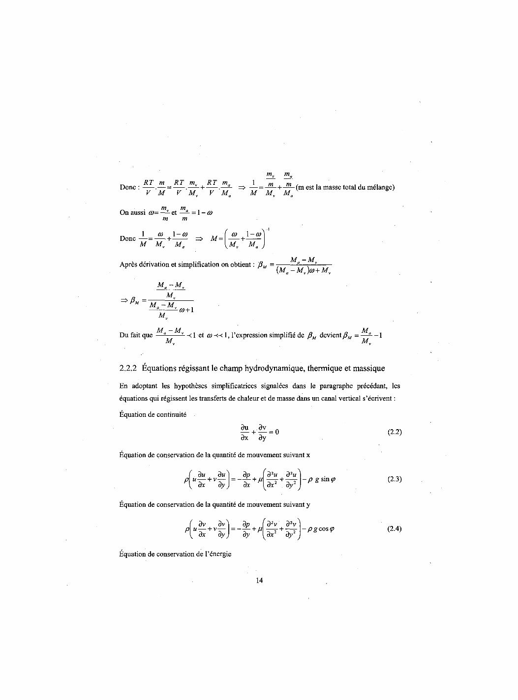
Done : = => —^L-(m est la masse total du melange) RT m^ RT ma
V 'M~ V 'M„ V 'M' M M„ M„
On aussi co= — et — = 1 -co m m
^ 1 co l-<y Done — = + M M„ M„
M = ( 1 CO 1 -co
Apres derivation et simplification on obtient: (5M = M-M„ {Ma-Mv)co+Mv
M a - M v
M„ M„ -M v-co+1
K
M -M M Du fait que — -< 1 et co« 1, l'expression simplifie de devient = — - - 1
M„ M„
/
2.2.2 Equations regissant le champ hydrodynamique, thermique et massique
En adoptant les hypotheses simplificatrices signalees dans le paragraphe precedant, les
equations qui regissent les transferts de chaleur et de masse dans un canal vertical s'ecrivent:
Equation de continuity
3u 3v . — + — = 0 dx dy
Equation de conservation de la quantite de mouvement suivant x
du du dx 3y dx
^ d2u d2u^ dxr + dyI - p gsmcp
(2.2)
(2.3)
Equation de conservation de la quantite de mouvement suivant y
- pgcos<p
ay yax ay J
Equation de conservation de l'energie
( dv Sv^) dp p\u — + v— =—— + M
\ dx dy) dy 'd2v 32VA
dx2 + dy2 (2.4)
14
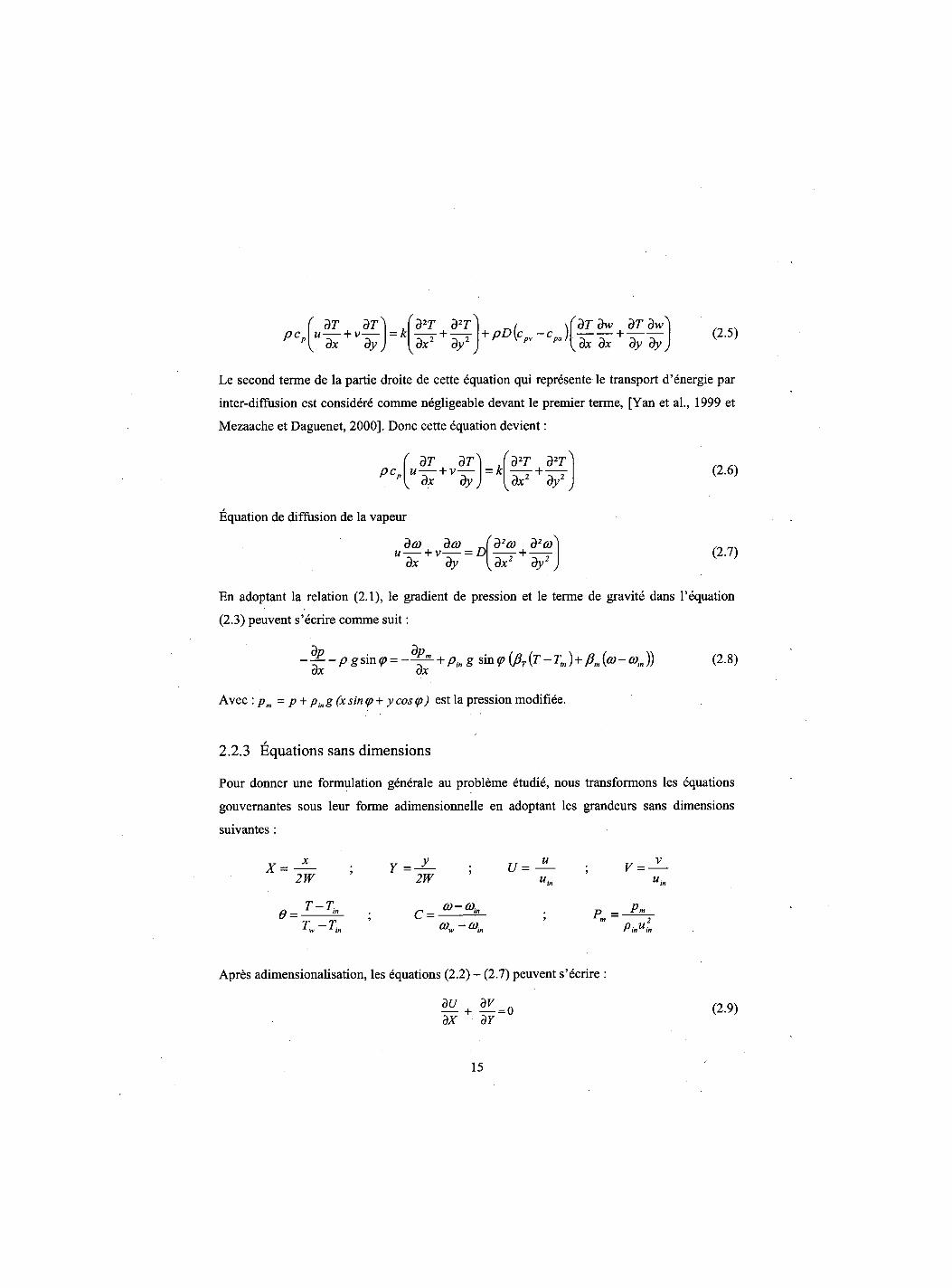
Pct dT dT
u — + v—— dx ay
^ Jd2T d2T^ = k dx2 dy2 PD(cpv-cpa)
^dT dw dT dw^ dx dx dy dy
(2.5)
Le second terme de la partie droite de cette equation qui represente le transport d'energie par
inter-diffusion est considere comme negligeable devant le premier terme, [Yan et al., 1999 et
Mezaache et Daguenet, 2000]. Done cette equation devient:
, dT dT PCp\Ulh+Vlfy
'd2T d2T) - k + — -
/ dx2 \ 3 / ,
(2.6)
Equation de diffusion de la vapeur
da) da) _ dx dy
rd2a) d2a + dx2 dy2 (2.7)
En adoptant la relation (2.1), le gradient de pression et le terme de gravite dans 1'equation
(2.3) peuvent s'ecrire comme suit:
-<t-pgsin<p = - ^ + ping sin <p (J3t {T -Tin) + (im {a)~ 0)t„)) (2.8) dx dx
Avec : pm = p + ping(x sin <p + y cos (p) est la pression modifiee.
2.2.3 Equations sans dimensions
Pour donner une formulation generale au probleme etudie, nous transformons les equations
gouvernantes sous leur forme adimensionnelle en adoptant les grandeurs sans dimensions
suivantes :
6 =
2W
T-T. T-T
Y 2W
U = V = -u.
C = (Q-G>in P = PMUL
Apres adimensionalisation, les equations (2.2) - (2.7) peuvent s'ecrire :
dx dY (2.9)
15
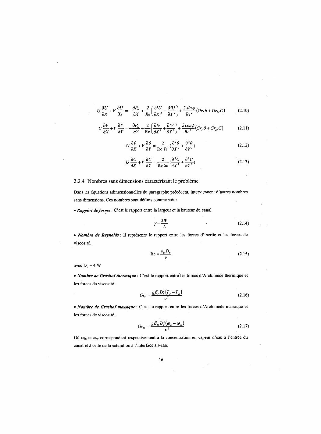
dX dY dX Re
dx dY 87 Re
d2U d2u\ 2sin<p ( ' „ .. 1A.
f d2V d2V ^ KdX2+dY2
y + ^ T ( G r T 9 + GrMC) (2.11)
Re
dx dY R cPr^dX2 dY2) K
TTdC TdC 2 ,d2C 32C. U — v-V = ( 1 ) (2.13) BX dY ReScW2 dY2' K J
2.2.4 Nombres sans dimensions caracterisant le probleme
Dans les equations adimensionnelles du paragraphe precedent, interviennent d'autres nombres
sans dimensions. Ces nombres sont definis comme suit:
Rapport de forme : C'est le rapport entre la largeur et la hauteur du canal.
2W r = - J - (2.14)
L i
• Nombre de Reynolds: II represente le rapport entre les forces d'inertie et les forces de
viscosite. R e = i l i !A ( 2 1 5 )
v
avec Dh = 4.W
• Nombre de Grashof thermique : C'est le rapport entre les forces d'Archimede thermique et
les forces de viscosite.
G SPrDl{T~Tin) ( 2 1 6 )
V
• Nombre de Grashof massique : C'est le rapport entre les forces d'Archimede massique et
les forces de viscosite.
Ou ©in et cow correspondent respectivement a la concentration en vapeur d'eau a l'entree du
canal et a celle de la saturation a l'interface air-eau.
16
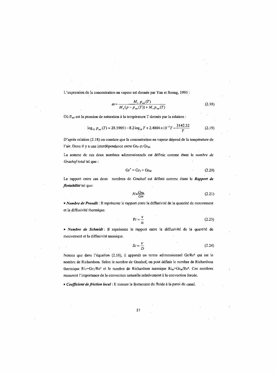
L'expression de la concentration en vapeur est donnee par Yan et Soong, 1995 :
*>= *Lp-<n (2.i8)
Ma{p-psat{T)) + Mvpsat{T)
Ou Psat est la pression de saturation a la temperature T donnee par la relation :
l°gio Psat(T) = 28.59051-8.2 log10 r + 2.4804xlO~3r--—^ :—^ (2.19)
D'apres relation (2.18) on constate que la concentration en vapeur depend de la temperature de
l'air. Done il y a une interdependance entre Grx et GrM.
La somme de ces deux nombres adimensionnels est definie comme etant le nombre de
Grashof total tel que : • "
Gr+ = GrT+GrM (2.20)
Le rapport entre ces deux nombres de Grashof est definit comme etant le Rapport de
flottabilite tel que:
N=@PL (2.21) Gm
• Nombre de Prandlt: II represente le rapport entre la diffusivite de la quantite de mouvement
et la diffusivite thermique.
Pr = - (2.23) a
• Nombre de Schmidt: II represente le rapport entre la diffusivite de la quantite de
mouvement et la diffusivite massique.
Sc = — (2.24) D
Notons que dans l'equation (2.10), il apparait un terme adimensionnel Gr/Re2 qui est le
nombre de Richardson. Selon le nombre de Grashof, on peut definir le nombre de Richardson
thermique RiT=GrT/Re2 et le nombre de Richardson massique Rim=Grm/Re2. Ces nombres
mesurent l'importance de la convection naturelle relativement a la convection forcee.
• Coefficient de friction local: II mesure le frottement du fluide a la paroi du canal.
17
dy (2.24)
y=0
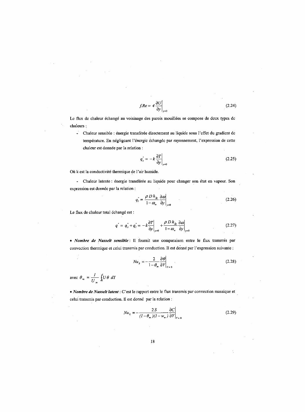
Le flux de chaleur echange au voisinage des parois mouillees se compose de deux types de
chaleurs:
- Chaleur sensible : energie transferee direetement au liquide sous 1'effet du gradient de
temperature. En negligeant l'energie echangee par rayonnement, l'expression de cette
chaleur est donnee par la relation :
dT qs = ~k
dy (2.25)
y=0
Ou k est la conductivity thermique de l'air humide.
- Chaleur latente : energie transferee au liquide pour changer son etat en vapeur. Son
expression est donnee par la relation :
ioDhfg da <h = 1 -Q)w By
(2.26) y=0
Le flux de chaleur total echange est:
<i' = q]+q"i = ~k dT dy
+ -PDhfg deo
y= 0 1 -G)w dy (2.27)
y=0
• Nombre de Nusselt sensible: II fournit une comparaison entre le flux transmis par
convection thermique et celui transmis par conduction. II est donne par l'expression suivante :
Nils =—s —-1-0. dY
(2.28) Y= 0
avec 6„ = 1 fi U.
jue dY
• Nombre de Nusselt latent: C'est le rapport entre le flux transmis par convection massique et
celui transmis par conduction. II est donne par la relation :
NUL=-2 S dC
(i-ej(i-wjdY (2.29)
r = o
18
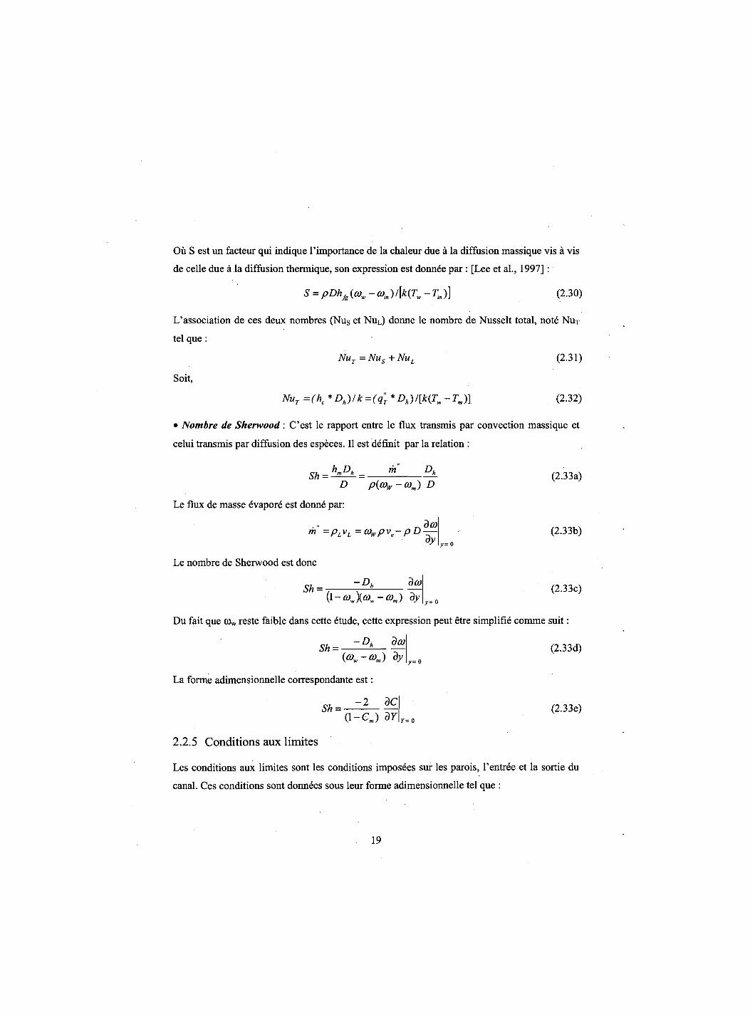
Ou S est un facteur qui indique 1'importance de la chaleur due a la diffusion massique vis a vis
de celle due a la diffusion thermique, son expression est donnee par : [Lee et al., 1997] :
S = pDhfg(a)w-0)in)/[k(Tw-Tin)] (2.30)
L'association de ces deux nombres (Nus et NuL) donne le nombre de Nusselt total, note NuT
tel que :
NUt = Nus + NUL (2.31)
Soit,
NuT=(hc*Dh)/k = (qT*Dh)/[k(Tw-TJ] (2.32)
• Nombre de Sherwood: C'est le rapport entre le flux transmis par convection massique et
celui transmis par diffusion des especes. II est definit par la relation :
Sh = - ~ - m Du
D p(a)lv-0)m) D
Le flux de masse evapore est donne par:
da) ™ =PLvL=0)wpve-pD dy y= 0
Le nombre de Sherwood est done
Sh = -Dh da) (1 -0)w\o)w-a)m) dy
(2.33a)
(2.33b)
(2.33c) y=0
Du fait que C0w reste faible dans cette etude, cette expression peut etre simplifie comme suit:
Sh = •Dh da) (0)W-0)J
La forme adimensionnelle correspondante est:
( i - e m ) dY
(2.33d) r= o
(2.33e) Y= 0
2.2.5 Conditions aux limites
Les conditions aux limites sont les conditions imposees sur les parois, l'entree et la sortie du
canal. Ces conditions sont donnees sous leur forme adimensionnelle tel que :
19
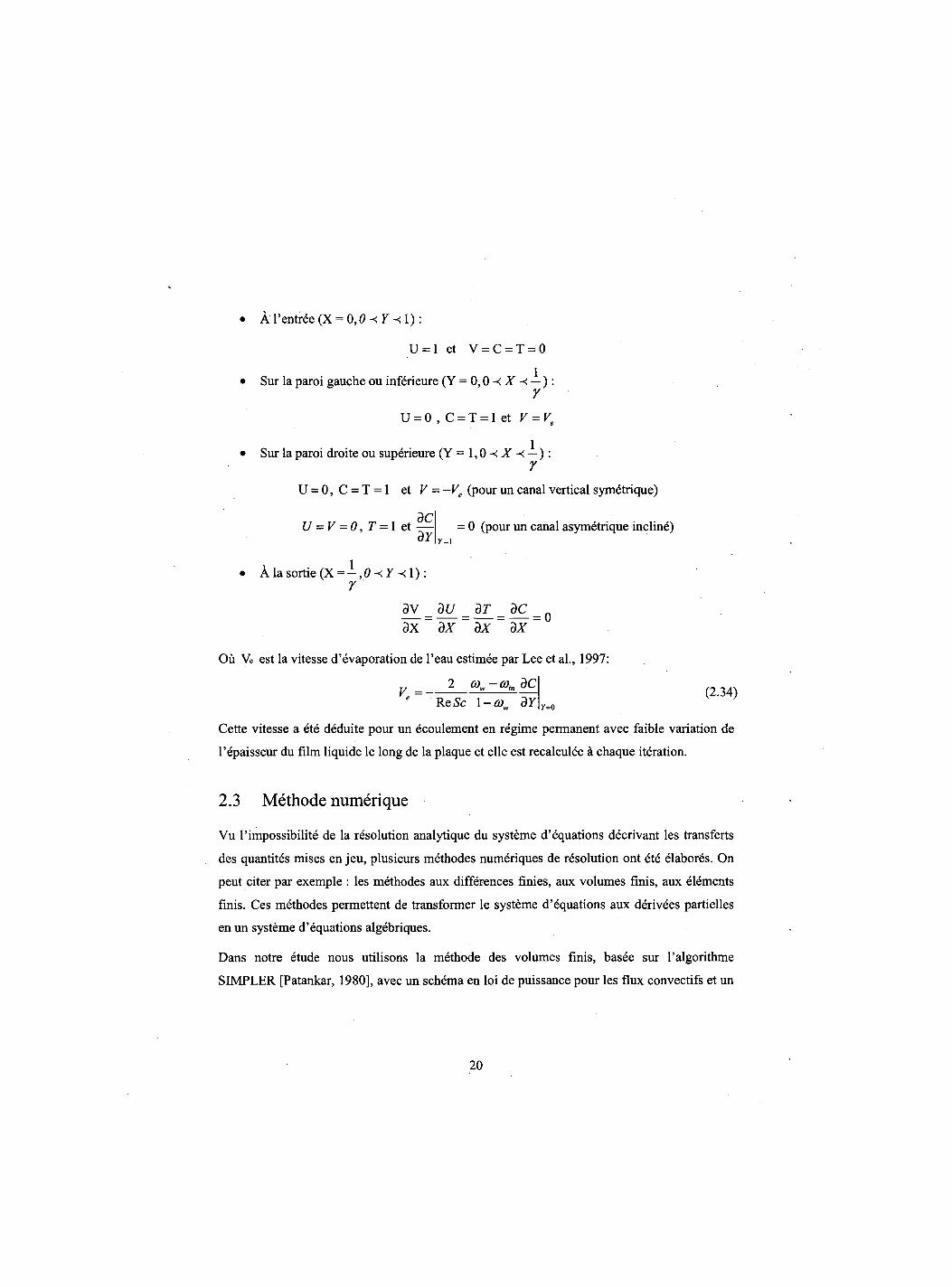
• A l'entree (X = 0,0 -< Y -<1):
U = 1 et V = C = T = 0
• Sur la paroi gauche ou inferieure (Y = 0 , — ) : 7
U = 0 , C = T = 1 et V = Ve
• Sur la paroi droite ou superieure (Y=1,0-<Jl '-< — ) : r
U = 0, C = T = 1 et V - -Ve (pour un canal vertical symetrique)
= 0 (pour un canal asymetrique incline) dC
U = V = 0,T = l e t — dY Y = 1
• A la sortie (X= —,0-<y-<l) : 7
3 V = d U =
d T =
d C = Q ax ~ dx dx~ dx~
Ou Ve est la vitesse d'evaporation de l'eau estimee par Lee et al., 1997:
2 0)w-o)indC V= — (2.34)
Y=0 Re 5c 1 -0)w dY
Cette vitesse a ete deduite pour un ecoulement en regime permanent avec faible variation de
l'epaisseur du film liquide le long de la plaque et elle est recalculee a chaque iteration.
2.3 Methode numerique
Vu 1'impossibility de la resolution analytique du systeme d'equations decrivant les transferts
des quantites mises en jeu, plusieurs methodes numeriques de resolution ont ete elabores. On
peut citer par exemple : les methodes aux differences finies, aux volumes finis, aux elements
finis. Ces methodes permettent de transformer le systeme d'equations aux derivees partielles
en un systeme d'equations algebriques.
Dans notre etude nous utilisons la methode des volumes finis, basee sur l'algorithme
SIMPLER [Patankar, 1980], avec un schema en loi de puissance pour les flux convectifs et un
20
schema centre pour les flux de diffusion. Nous presentons par la suite un apergu sur cette
methode.
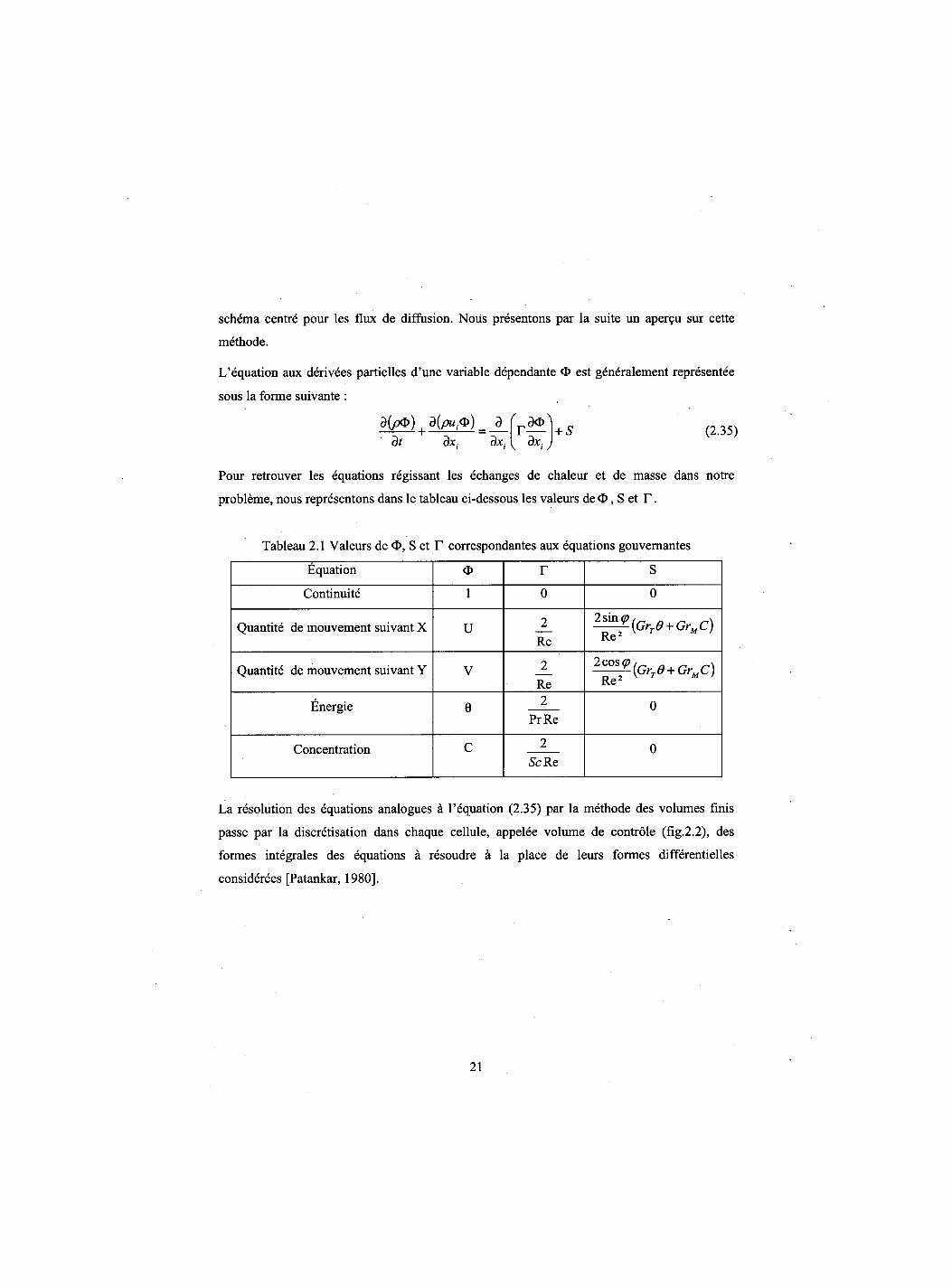
L'equation aux derivees partielles d'une variable dependante <D est generalement representee
sous la forme suivante :
a(po) {d{pu,o)_ d dt dx, dx, V dxiJ
+ S (2.35)
Pour retrouver les equations regissant les echanges de chaleur et de masse dans notre
probleme, nous representons dans le tableau ci-dessous les valeurs de O, S et T .
Tableau 2.1 Valeurs de O, S et T correspondantes aux equations gouvernantes
Equation <D r S
Continuite 1 0 0
Quantite de mouvement suivant X U 2 Re
2sin ©/_, . _ Re2
Quantite de mouvement suivant Y V 2 Re
2cos(p ^q 0 + Qr c) Re ̂ M '
Energie e 2 PrRe
0
Concentration c 2 Sc Re
0
La resolution des equations analogues a l'equation (2.35) par la methode des volumes finis
passe par la discretisation dans chaque cellule, appelee volume de controle (fig.2.2), des
formes integrales des equations a resoudre a la place de leurs formes differentielles
considerees [Patankar, 1980].
21
N *
AX
S
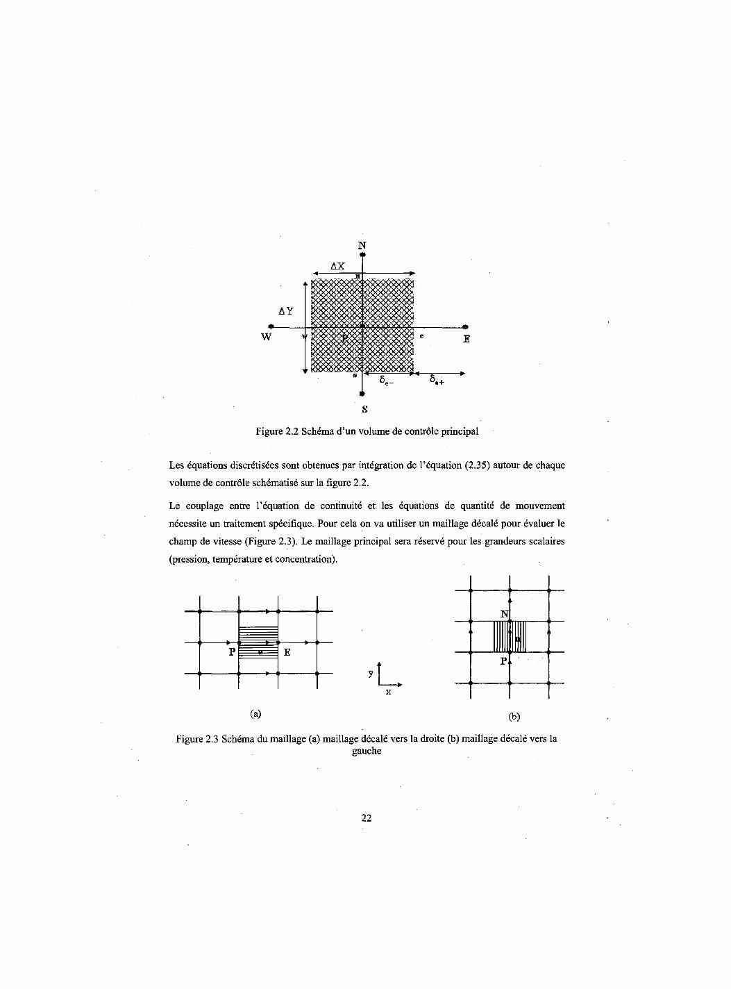
Figure 2.2 Schema d'un volume de controle principal
Les equations discretisees sont obtenues par integration de l'equation (2.35) autour de chaque
volume de controle schematise sur la figure 2.2.
Le couplage entre l'equation de continuite et les equations de quantite de mouvement
necessite un traitement specifique. Pour cela on va utiliser un maillage decale pour evaluer le
champ de vitesse (Figure 2.3). Le maillage principal sera reserve pour les grandeurs scalaires
(pression, temperature et concentration).
x
(a) (b)
Figure 2.3 Schema du maillage (a) maillage decale vers la droite (b) maillage decale vers la gauche
22
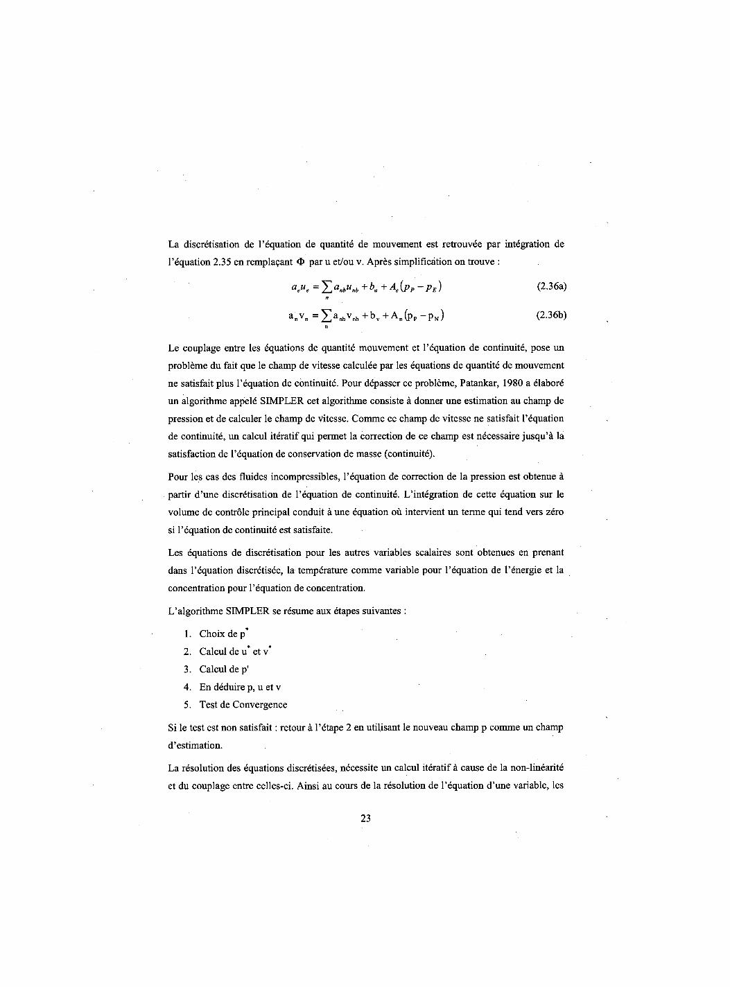
La discretisation de l'equation de quantite de mouvement est retrouvee par integration de
l'equation 2.35 en rempla?ant <D par u et/ou v. Apres simplification on trouve :
aeue =YJa«bUnb+bu + M P P ~ PE) ( 2 " 3 6 A ) n
anvn = ^ a n b v n b + b v + A n ( p p - p N ) (2.36b) n
Le couplage entre les equations de quantite mouvement et l'equation de continuity, pose un
probleme du fait que le champ de vitesse calculee par les equations de quantite de mouvement
ne satisfait plus l'equation de continuity. Pour depasser ce probleme, Patankar, 1980 a elabore
un algorithme appele SIMPLER cet algorithme consiste a donner une estimation au champ de
pression et de calculer le champ de vitesse. Comme ce champ de vitesse ne satisfait l'equation
de continuity, un calcul iteratif qui permet la correction de ce champ est necessaire jusqu'a la
satisfaction de l'equation de conservation de masse (continuity).
Pour les cas des fluides incompressibles, l'equation de correction de la pression est obtenue a
partir d'une discretisation de l'equation de continuity. L'integration de cette equation sur le
volume de controle principal conduit a une equation ou intervient un terme qui tend vers zero
si l'equation de continuity est satisfaite.
Les equations de discretisation pour les autres variables scalaires sont obtenues en prenant
dans l'equation discretisee, la temperature comme variable pour l'equation de l'energie et la
concentration pour l'equation de concentration.
L'algorithme SIMPLER se resume aux etapes suivantes :
1. Choix de p*
2. Calcul de u* et v*
3. Calcul dep'
4. En deduire p, u et v
5. Test de Convergence
Si le test est non satisfait: retour a l'etape 2 en utilisant le nouveau champ p comme un champ
d'estimation.
La resolution des equations discretisees, necessite un calcul iteratif a cause de la non-linearite
et du couplage entre celles-ci. Ainsi au cours de la resolution de l'equation d'une variable, les
23
autres variables sont considerees constantes et leurs valeurs sont egales a celles de l'iteration
qui precede. Ce processus d'iteration est repete jusqu'a convergence de toutes les variables. Le
critere de convergence comprend deux indicateurs bases sur la masse residuelle resultant de
l'integration de l'equation de continuity sur un volume de controle. Ces indicateurs sont
definis comme etant la plus grande valeur (SMAX) et la somme algebrique (SSUM) de la
masse residuelle a travers tout le domaine de calcul. lis doivent etre inferieurs a 10"6.
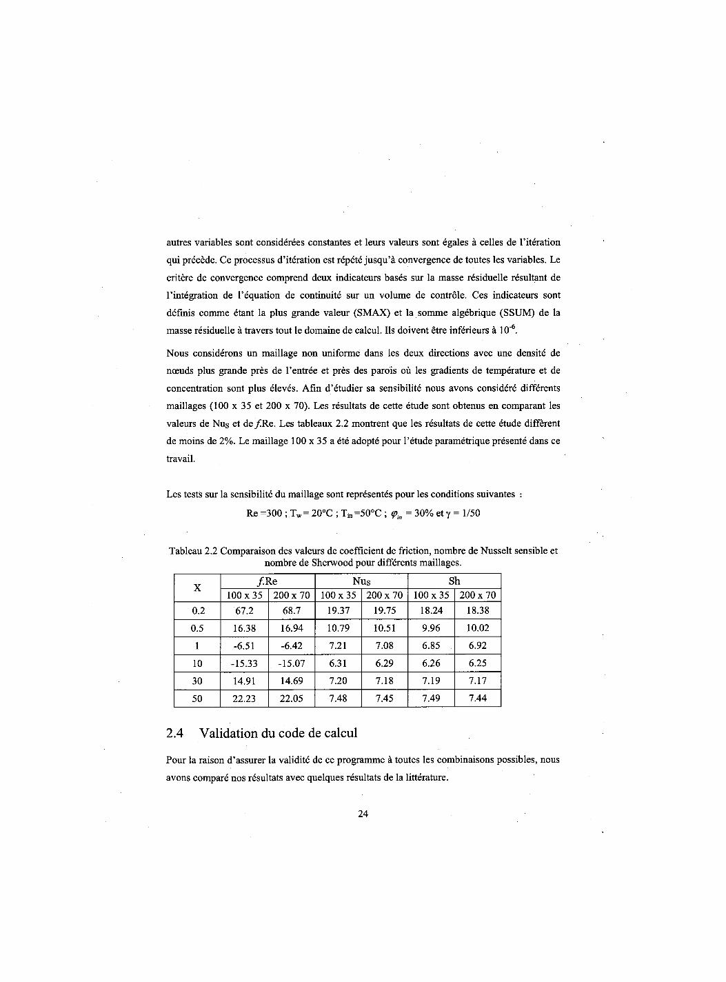
Nous considerons un maillage non uniforme dans les deux directions avec une densite de
nceuds plus grande pres de l'entree et pres des parois ou les gradients de temperature et de
concentration sont plus eleves. Afin d'etudier sa sensibilite nous avons considere differents
maillages (100 x 35 et 200 x 70). Les resultats de cette etude sont obtenus en comparant les
valeurs de Nus et de /Re . Les tableaux 2.2 montrent que les resultats de cette etude different
de moins de 2%. Le maillage 100 x 35 a ete adopte pour l'etude parametrique presente dans ce
travail.
Les tests sur la sensibilite du maillage sont representes pour les conditions suivantes :
Re =300 ; Tw= 20°C ; Tj„ =50°C ; (pin = 30% et y = 1/50
Tableau 2.2 Comparaison des valeurs de coefficient de friction, nombre de Nusselt sensible et nombre de Sherwood pour differents maillages.
X / .Re Nus Sh X
100x35 200 x 70 100x35 200 x 70 100x35 200 x 70 0.2 67.2 68.7 19.37 19.75 18.24 18.38
0.5 16.38 16.94 10.79 10.51 9.96 10.02
1 -6.51 -6.42 7.21 7.08 6.85 6.92
10 -15.33 -15.07 6.31 6.29 6.26 6.25
30 14.91 14.69 7.20 7.18 7.19 7.17
50 22.23 22.05 7.48 7.45 7.49 7.44
2.4 Validation du code de calcul
Pour la raison d'assurer la validite de ce programme a toutes les combinaisons possibles, nous
avons compare nos resultats avec quelques resultats de la litterature.
24
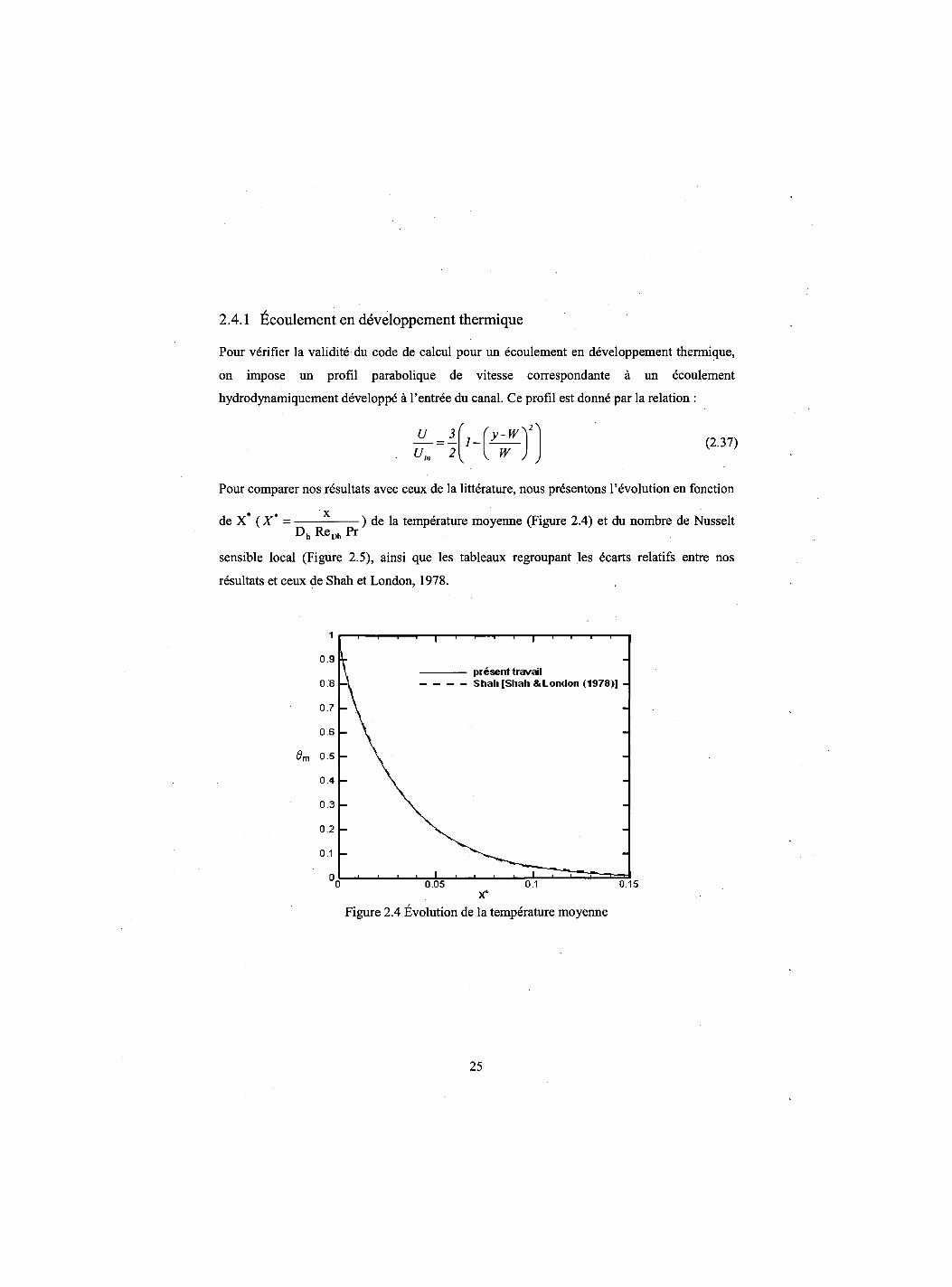
2.4.1 Ecoulement en developpement thermique
Pour verifier la validite du code de calcul pour un ecoulement en developpement thermique,
on impose un profil parabolique de vitesse correspondante a un ecoulement
hydrodynamiquement developpe a l'entree du canal. Ce profil est donne par la relation :
U _ 3 ~ 2
1-w J
(2.37)
Pour comparer nos resultats avec ceux de la litterature, nous presentons 1'evolution en fonction
de X* ( X ' = Dh ReDh Pr
) de la temperature moyenne (Figure 2.4) et du nombre de Nusselt
sensible local (Figure 2.5), ainsi que les tableaux regroupant les ecarts relatifs entre nos
resultats et ceux de Shah et London, 1978.
8m 0.5
present travail Shah [Shah & London (1978)] -
0.15
Figure 2.4 Evolution de la temperature moyenne
25
20
15 - — present Ira vail - Shah [shah & Lontlon<1978>]
Nil,
10
5 -
0.05 0 . 1 0.15
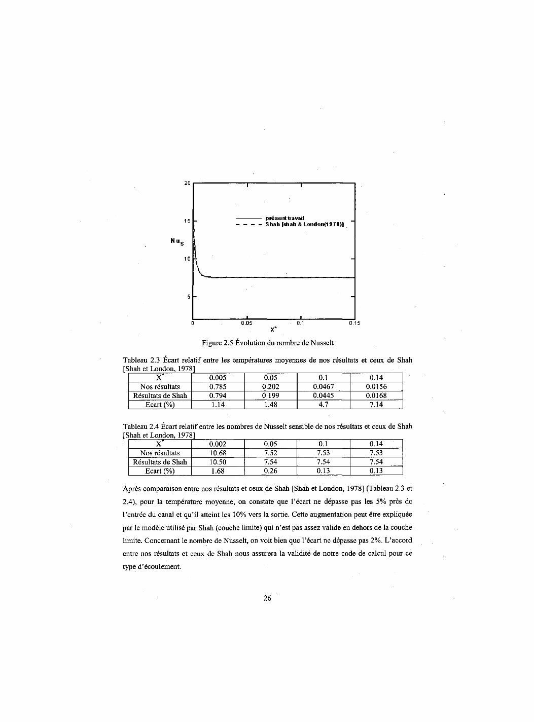
Figure 2.5 Evolution du nombre de Nusselt
Tableau 2.3 Ecart relatif entre les temperatures moyennes de nos resultats et ceux de Shah
X* 0.005 0.05 0.1 0.14 Nos resultats 0.785 0.202 0.0467 0.0156
Resultats de Shah 0.794 0.199 0.0445 0.0168 Ecart (%) 1.14 1.48 4.7 7.14
Tableau 2.4 Ecart relatif entre les nombres de Nusselt sensible de nos resultats et ceux de Shah
X* 0.002 0.05 0.1 0.14 Nos resultats 10.68 7.52 7.53 7.53
Resultats de Shah 10.50 7.54 7.54 7.54 Ecart (%) 1.68 0.26 0.13 0.13
Apres comparaison entre nos resultats et ceux de Shah [Shah et London, 1978] (Tableau 2.3 et
2.4), pour la temperature moyenne, on constate que l'ecart ne depasse pas les 5% pres de
l'entree du canal et qu'il atteint les 10% vers la sortie. Cette augmentation peut etre expliquee
par le modele utilise par Shah (couche limite) qui n'est pas assez valide en dehors de la couche
limite. Concernant le nombre de Nusselt, on voit bien que l'ecart ne depasse pas 2%. L'accord
entre nos resultats et ceux de Shah nous assurera la validite de notre code de calcul pour ce
type d'ecoulement.
26
2.4.2 Ecoulement en developpement simultane
Pour verifier la validite des resultats obtenus par resolution simultane des equations de
quantite de mouvement et de l'energie en convection forcee, on compare ces resultats avec
ceux de Hwang [Shah et London, 1978].
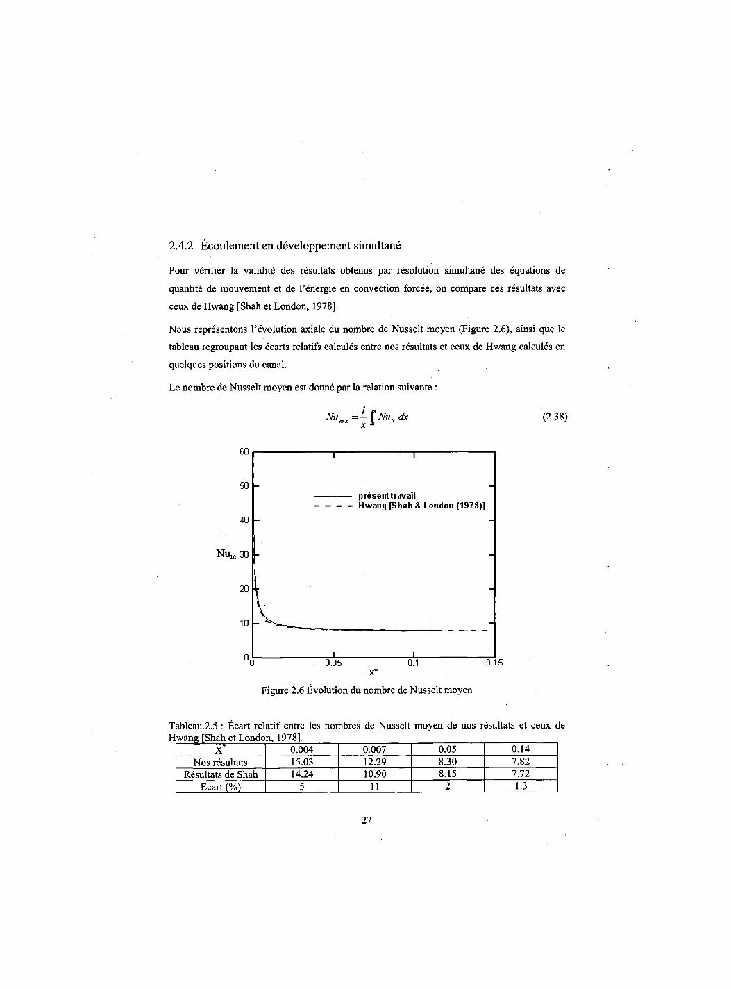
Nous representons 1'evolution axiale du nombre de Nusselt moyen (Figure 2.6), ainsi que le
tableau regroupant les ecarts relatifs calcules entre nos resultats et ceux de Hwang calcules en
quelques positions du canal.
Le nombre de Nusselt moyen est donne par la relation suivante :
Num,x=-[Nuxdx (2.38) r
Figure 2.6 Evolution du nombre de Nusselt moyen
Tableau.2.5 : Ecart relatif entre les nombres de Nusselt moyen de nos resultats et ceux de Hwang [Shah et London, 1978],
X* 0.004 0.007 0.05 0.14 Nos resultats 15.03 12.29 8.30 7.82
Resultats de Shah 14.24 10.90 8.15 7.72 Ecart (%) 5 11 2 1.3
27

En comparant nos resultats a ceux de Hwang, on remarque que dans la plupart de la longueur
du canal les resultats sont en accord. En effet, cet ecart ne depasse pas 5% pour X* < 0.006 et
X* > 0.011, c'est a dire sur 96.7% de la longueur du canal, alors que cet ecart peut atteindre
11% dans la zone qui reste. Ce dernier ecart assez important est probablement du au modele
de couche limite utilise par cet auteur qui neglige la diffusion axiale de la chaleur. Cet effet
joue un role tres important pres de l'entree du canal comme le montre Nesreddine, 1997. Done
nous pouvons s'assurer de la validite de ce code de calcul concernant 1'etude de ce type
d'ecoulement.
2.4.3 Ecoulement en developpement thermique avec transfert de masse
Comme troisieme test, la validation a ete faite pour assurer la validite des resultats obtenus par
la resolution de l'equation d'energie. La comparaison est faite avec les resultats de Yan et Lin,
1989 pour un ecoulement en developpement thermique avec transfert de masse dont le nombre
de Reynolds a l'entree du canal est de 400, une temperature d'entree de 20°C et une humidite
d'entree de 50%. La temperature des parois humides est de 40°C.
Les resultats obtenus pour les nombres de Nusselt latent est sensible sont presentes sur les
figures 2.7 et 2.8, respectivement, ainsi que les tableaux regroupant les ecarts entre nos
resultats et ceux de Yan et Lin, 1989.
100
80 Present travail Yan (1989)
60
NllL 40
20
0 0 0.1 0.2 0.3 0.4 4x/hRe
0.5 0.6
Figure 2.7 Evolution du nombre de Nusselt latent
28
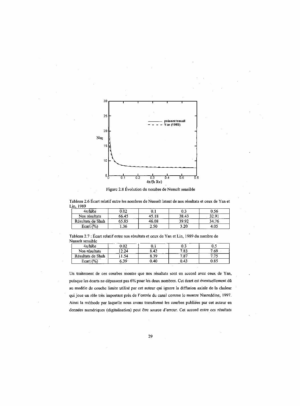
Figure 2.8 Evolution du nombre de Nusselt sensible
Tableau 2.6 Ecart relatif entre les nombres de Nusselt latent de nos resultats et ceux de Yan et Lin, 1989
4x/hRe 0.02 0.1 0.3 0.56 Nos resultats 66.45 45.18 38.43 32.91
Resultats de Shah 65.85 46.08 39.92 34.76 Ecart (%) 1.36 2.50 3.20 4.05
ableau 2.7 : Ecart relatif entre nos resultats et ceux de Yan et Lin, 1989 du nombre de usselt sensible
4x/hRe 0.02 0.1 0.3 0.5 Nos resultats 12.24 8.42 7.83 7.69
Resultats de Shah 11.54 8.39 7.87 7.75 Ecart (%) 6.39 0.40 0.43 0.85
Un traitement de ces courbes montre que nos resultats sont en accord avec ceux de Yan,
puisque les ecarts ne depassent pas 6% pour les deux npmbres. Cet ecart est eventuellement du
au modele de couche limite utilise par cet auteur qui ignore la diffusion axiale de la chaleur
qui joue un role tres important pres de l'entree du canal comme le montre Nasreddine, 1997.
Ainsi la methode par laquelle nous avons transforme les courbes publiees par cet auteur en
donnees numeriques (digitalisation) peut etre source d'erreur. Cet accord entre ces resultats
29
nous permet de nous assurer de la validite de notre code de calcul concernant l'etude de ce
type d'ecoulement.
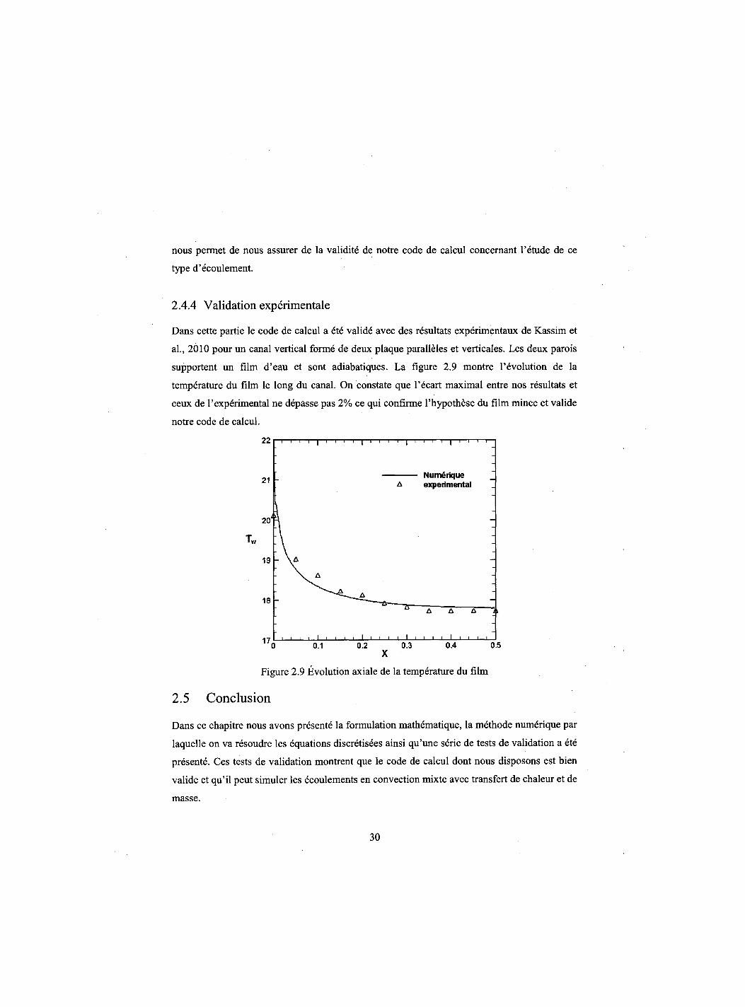
2.4.4 Validation experimentale
Dans cette partie le code de calcul a ete valide avec des resultats experimentaux de Kassim et
al., 2010 pour un canal vertical forme de deux plaque paralleles et verticales. Les deux parois
supportent un film d'eau et sont adiabatiques. La figure 2.9 montre 1'evolution de la
temperature du film le long du canal. On constate que l'ecart maximal entre nos resultats et
ceux de l'experimental ne depasse pas 2% ce qui confirme l'hypothese du film mince et valide
notre code de calcul.
Figure 2.9 Evolution axiale de la temperature du film
2.5 Conclusion
Dans ce chapitre nous avons presente la formulation mathematique, la methode numerique par
laquelle on va resoudre les equations discretisees ainsi qu'une serie de tests de validation a ete
presente. Ces tests de validation montrent que le code de calcul dont nous disposons est bien
valide et qu'il peut simuler les ecoulements en convection mixte avec transfert de chaleur et de
masse.
30
CHAPITRE 3 Combined buoyancy effects of thermal and mass diffusion on laminar convection in a vertical isothermal channel
Auteurs et affiliation: O. OULAID: etudiant au doctorat, Universite de Sherbrooke, Faeulte de genie, Departement de genie mecanique en cotutelle avec l'Universite Cadi Ayyad, Faeulte des sciences-Semlalia, Departement de physique, Marrakech 40 001, Maroc.
B. BENHAMOU: professeur, Universite Cadi Ayyad, Faeulte des sciences-Semlalia, Departement de physique, Marrakech 40 001, Maroc.
N. GALANIS: professeur, Universite de Sherbrooke, Faeulte de genie, Departement de genie mecanique.
Date d'acceptation : Mars 2009
Etat de 1'acceptation : publie
Revue: Computational Thermal Sciences
Reference: Oulaid, O. Benhamou, B. and Galanis, N. (2010). "Combined buoyancy effects
of thermal and mass diffusion on laminar convection in a vertical isothermal
channel", International Journal of Computational Thermal Sciences, Vol. 2, No.
2, pp. 125-138.
Titre fran9ais: Effets combines des forces d'Archimede d'origine thermique et massique sur la convection laminaire dans canal vertical isotherme.
31
Resume:
Cet article traite numeriquement de la convection laminaire mixte avec changement de phase
entre deux plaques planes paralleles. Les plaques sont mouillees avec un film d'eau et
imposees a une temperature constante inferieure a celle de l'air a l'entree du canal. Ce dernier
est traverse par un ecoulement d'air humide et chaud en regime laminaire. Les resultats de
cette etude montrent que ces forces ont un effet important sur les champs hydrodynamique,
thermique et massique. Ainsi ces forces reduisent le transfert de chaleur et de masse et causent
le renversement de l'ecoulement pret des parois. Dans la premiere moitie du canal, le nombre
de Nusselt latent calcule dans le cas de la convection mixte est inferieur a celui calcule dans
du cas de la convection forcee. Cette tendance se renverse dans la seconde moitie du canal. De
plus, nous avons confirme que le transfert par chaleur latente est plus important compare a
celui par chaleur sensible. Le rapport entre le nombre de Nusselt latent et sensible est de 7 a
l'entree du canal alors qu'il est de 3 a sa sortie.
Mots cles: Canal vertical, Transfert de chaleur et de masse, Convection mixte et forcee,
Changement de phase, Condensation, Force d'Archimede, renversement d'ecoulement.
32
Abstract
This paper reports on a numerical study of laminar mixed convection flow associated with
mass transfer and phase change in a vertical parallel-plate channel. The plates are wetted by
thin liquid water films and maintained at a constant temperature lower than that of the air
entering the channel. The solution of the governing equations is based on the finite volume
method with the well-known SIMPLER algorithm for handling the velocity-pressure coupling.
Numerical results show that buoyancy forces have an important effect on the hydrodynamic
field as well as on the heat- and mass- transfer characteristics. These forces induce a flow
reversal. Additionally, heat transfer associated with phase change (i.e. latent heat transfer) is
more important compared with sensible heat transfer.
Keywords: Vertical channel, heat and mass transfer, mixed and forced convection, phase
change, condensation, buoyancy forces, flow reversal.
33
3.1 Introduction
Simultaneous heat and mass transfer with phase change is present in many natural and
engineering processes such as human transpiration, desalination, refrigeration and air
conditioning. This problem has therefore been studied extensively, mostly numerically since
the number of independent variables influencing the hydrodynamic, thermal and concentration
fields is quite large and their control in experimental installations is rather difficult. Lin et al.
(1988) investigated the role of vaporization of a thin liquid water film falling on the wall of a
vertical tube in laminar mixed convection. The authors assumed constant thermophysical
properties evaluated at a reference temperature Tref and mass fraction curef obtained by these
expressions: Tref = (2TW + Tm) / 3 and coref - (2&>w + co\n) / 3, where 7W , 7jn, cuw and com are
respectively the tube wall and inlet air temperatures and mass fractions. This way of
evaluating thermophysical properties, known as the one-third rule, has been used previously in
the literature (Hubbard el al. 1975; Chow and Chung 1983). Chow and Chung (1983)
performed a numerical study of evaporation of water in a laminar air stream. The water
surface temperature was assumed to be constant and equal to the wet bulb temperature of the
free stream. Different airflow temperatures were considered (150-500°C). By comparing the
results of their models with variable and constant properties evaluated by the one-third rule,
the authors concluded that the latter agree well with the variable-property results, even at high
airflow temperatures. Earlier, Hubbard et al. (1975) conducted a numerical study on a single
droplet evaporation of octane in stagnant air. The initial temperature of the droplet was 27°C
and the air temperature was varied in the range 327-1727°C. By comparing their results using
various reference property temperatures and concentrations, they concluded that the one-third
rule yields the best agreement with the variable-properties model.
Lin et al. (1988) assumed an extremely thin liquid film so that it could be treated as a
boundary condition. This assumption was extensively used in the literature (Huang et al. 2005;
Azizi et al. 2007; Ait Hammou et al. 2004). Yan (1993) investigated the validity of this
assumption, for both air-water and air-ethanol systems. The author carried out a numerical
study of laminar mixed convection associated with evaporation of a falling liquid film along a
vertical parallel-plate channel. Both of the plates are heated with a constant temperature.
Results obtained by including transport in the liquid film are compared to those corresponding
34
to the extremely thin liquid film assumption. The major conclusion of the author is that this
assumption is valid for systems with small liquid mass flow rates. The effects of evaporation
of liquid film on the transfer of heat and mass by laminar natural convection in a vertical
parallel-plate channel were carried out both experimentally and numerically by Yan et al.
(1991) and Yan and Lin, 1991. Both of the plates are thermally insulated and wetted by a thin
ethanol liquid film. The film temperature was higher than that of the downward airflow at the
entrance. The numerical study used a boundary layer model in both liquid and gas flows,
including the interfacial wave effects. The results showed that the influence of the evaporative
latent heat transfer on the cooling of the liquid film depended largely on the inlet film
temperature and mass flow rate. Ait Hammou et al. (2004) analyzed numerically the effects of
simultaneous heat and mass transfer on the downward laminar flow of humid air in an
isothermal vertical channel with wet walls. The authors stated that, depending on the inlet
conditions of the flowing humid air, mass transfer might result in liquid film evaporation or
condensation of water vapour, but the thermal and mass diffusion buoyancy forces have
significant effects on flow characteristics. Huang et al. (2005) conducted a numerical study on
laminar mixed convection heat and mass transfer in a rectangular duct. Two of the duct walls
were wetted by a thin liquid water film and maintained at different constant temperatures. The
other walls are insulated. Air entered the duct with a constant temperature lower than that of
the walls and different relative humidities. The authors established that film evaporation as
well as vapor condensation occurred on the wall with lower temperature. Recently, a
numerical study of buoyancy effects on laminar mixed convection heat and mass transfer in a
vertical channel was conducted by Azizi et al. (2007). They used a parallel-plate channel with
isothermal and wetted walls. Both upward and downward simultaneously developing flows
were considered. An interesting result of this study is that flow reversal was predicted and
computed for an upward flow with a relatively high temperature difference between the
incoming air and the walls. Flow reversal of a fully developed flow, associated with heat and
mass transfer, was investigated analytically by Salah El-Din (1992), and Boulama-Galanis
(2004). These authors presented a criterion of occurrence of flow reversal.
The objective of the present study is to numerically investigate the combined buoyancy
effects of thermal and mass diffusion on an upward laminar flow in a vertical parallel-plate
channel with flow reversal.
35
3.2 Description and Modeling
Ambient air with a uniform dry bulb temperature 7i„ and a uniform relative humidity <|)jn
entered a vertical parallel-plate channel with a uniform upward velocity um. The plates are
covered by a very thin liquid water film and maintained at the same constant temperature 7W
lower than that of the entering airflow (Figure 3.1).
We assume that the liquid films were extremely thin so that they could be treated as a
boundary condition. This simplification allowed us to handle only the conservation equations
in the gas flow. The liquid film was therefore assumed to be at the wall temperature. As
reported above, it was demonstrated that this assumption is valid for small liquid mass flow
rates (Yan, 1993). Steady state conditions were considered and the flow is assumed to be
laminar. Viscous dissipation, radiation heat transfer, and other secondary effects (such as
pressure work, energy transport by the interdiffusion of species, Dufour and Soret effects)
were assumed to be negligible (Gebhart and Pera, 1971). Finally, the physical properties were
taken constant, except for the density in the body forces, which was considered to be a linear
function of temperature and mass fraction (Oberbeck-Boussinesq approximation) (Nield and
Bejan, 2006).
P = P^-PAT-Tin)-PM{c0-(0in)] (3.1)
For the air-water combination under consideration, both pT and Pm are positive. However, this is
not the case for all gas-liquid combinations.
36
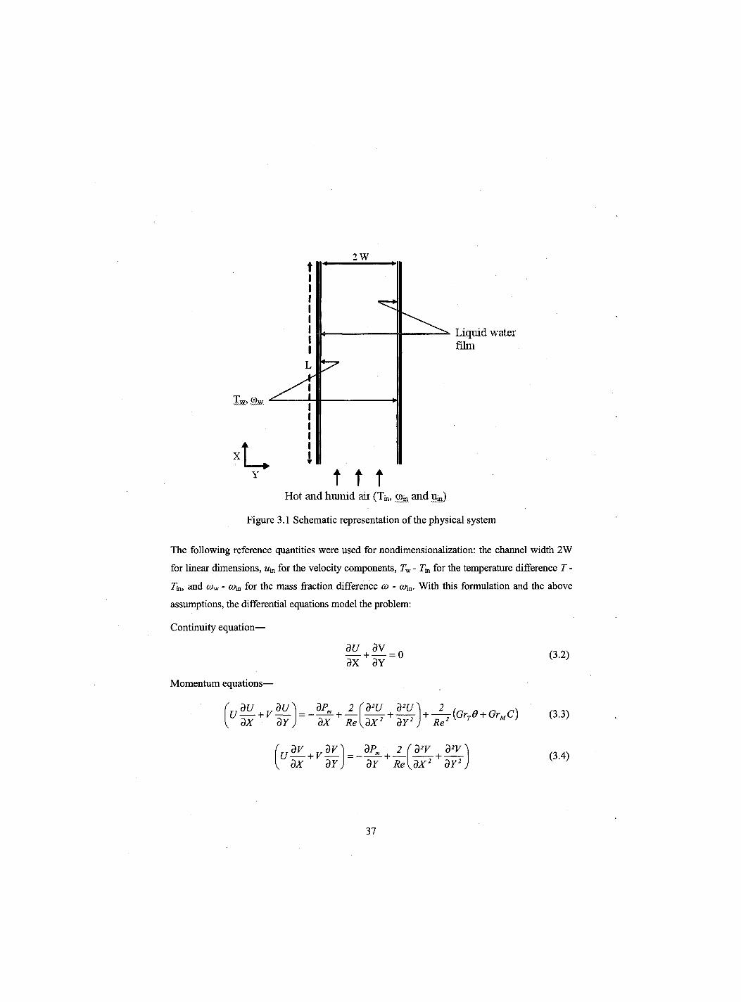
2 W
Liquid water film
t t t Hot and humid aii' (Tm, co^ and uffi)
Figure 3.1 Schematic representation of the physical system
The following reference quantities were used for nondimensionalization: the channel width 2W
for linear dimensions, um for the velocity components, Tw - Tm for the temperature difference T -
7in, and cow - com for the mass fraction difference co - tom. With this formulation and the above
assumptions, the differential equations model the problem:
Continuity equation—
dU 3v - + = 0
3X 3Y
Momentum equations—
3 1 37 j dP„
• +
dX Re 2 (d3U d2U^ +
dX2 dY2 Re' -{GrT6 + GrMC)
dx 37 dPm 2 —2- + — dY Re
rd2V d2Vy
KdX2 + dY2 j
(3.2)
(3.3)
(3.4)
37
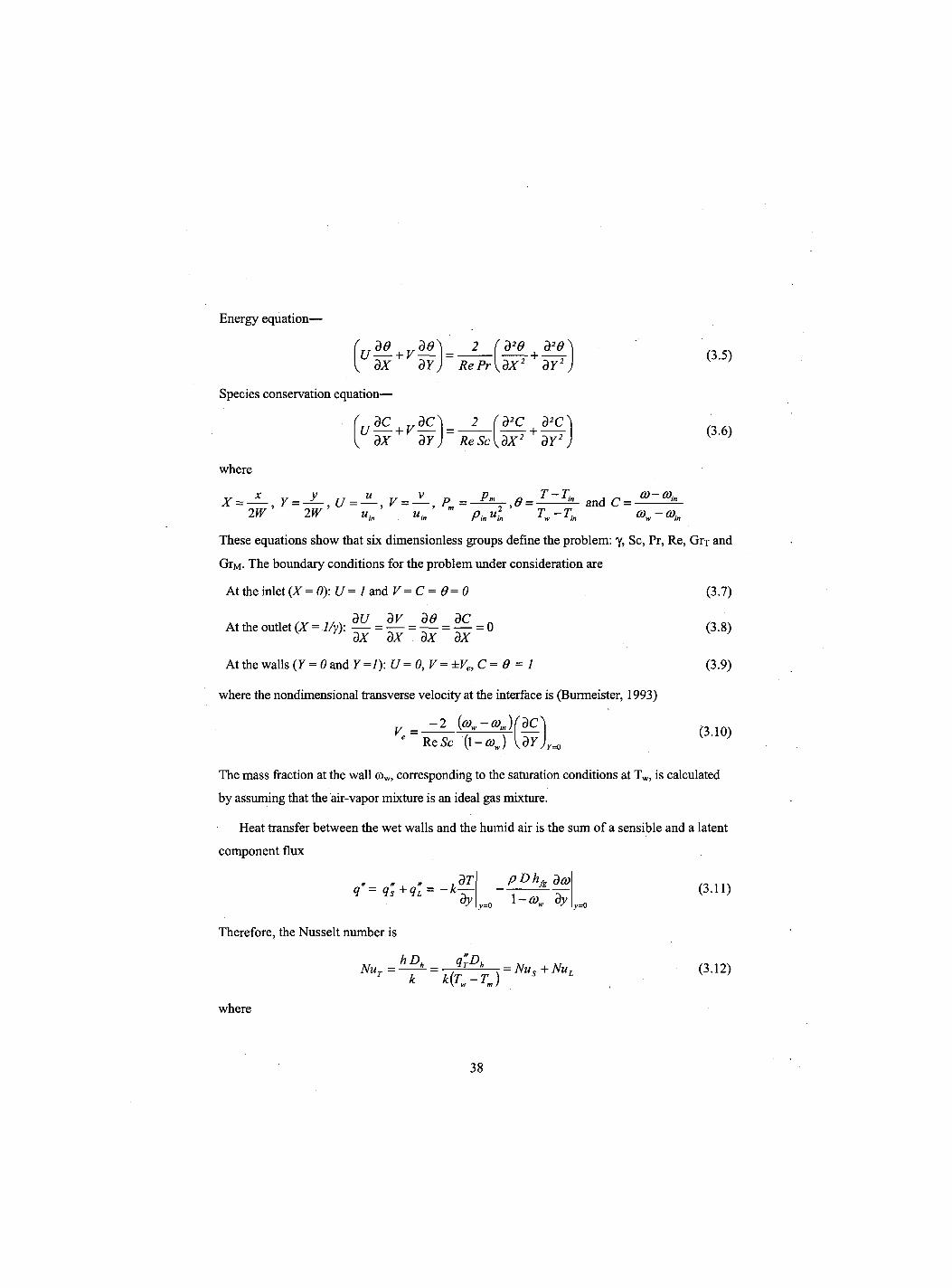
Energy equation-
dx dY 2 fd29 | d20\
RePr\dX2 dY2 J (3.5)
Species conservation equation—
U d c+ v * l =
dX dY J ReSc
(d2C + •
dx2 dY2 (3.6)
where
X = — , y = -2-,U = -±, V = Pm = and C = 2W 2W u,n uin pin ufn T„ -T„ w in
These equations show that six dimensionless groups define the problem: y, Sc, Pr, Re, Grx and
GrM. The boundary conditions for the problem under consideration are
At the inlet (X = 0): U = 1 and V = C - 9= 0 (3.7)
a*A t/^ d U d V d e d C n At the outlet (X = 1/y): = — = — = — = 0 " dx dx dx dx
At the walls (Y=0mdY=l): U = 0, V = ±Ve, C = 9 = 1
where the nondimensional transverse velocity at the interface is (Burmeister, 1993)
- 2 (cow-co in)(dCN
V. = Re Sc (1 -0)J dY
(3.8)
(3.9)
(3.10)
The mass fraction at the wall oow, corresponding to the saturation conditions at Tw, is calculated
by assuming that the air-vapor mixture is an ideal gas mixture.
Heat transfer between the wet walls and the humid air is the sum of a sensible and a latent
component flux
" " t » 7 q = <is +<1L = ~k dT dy
pDhf da?
=0 dy
(3.11) y=0
Therefore, the Nusselt number is
NUT = H 1TD, k k(Tw-Tm)
h = Nus + NUL (3.12)
where
38
2 dO Nu, = 1-0. dY Y = 0
NUL =-2 S dC
1-0. d Y
(3.13)
(3.14)
and
S = PDhfAcow-coin) 1 (3.15)
k (1 ' - © J (Tw-Tin)
S represents the relative importance of energy transport through species diffusion to that
through thermal diffusion.
The Sherwood number characterizes mass transfer at the interface
h.Dk 2 dC Sh = D 1 - C _ dY Y= 0
while the friction factor is
/ . R e = 4 'dU' V Jy=0
The dimensionless bulk temperature is defined as follows
0m=— [U0dY M U *
and
C = — f t / C i / r
(3.16)
(3.17)
(3.18)
(3.19)
3.3 Numerical method
The solution of the partial differential equations modelling the flow field and heat-mass transfers
is based on the finite volume method. The velocity-pressure coupling is treated with the
SIMPLER algorithm (Patankar 1980). Convergence of this iterative procedure is declared when
the relative variation of any dependent variable is less than 10^ and if the mass source residual
falls below 10"6 at all the grid points. The grid is non-uniform in both the streamwise and
39
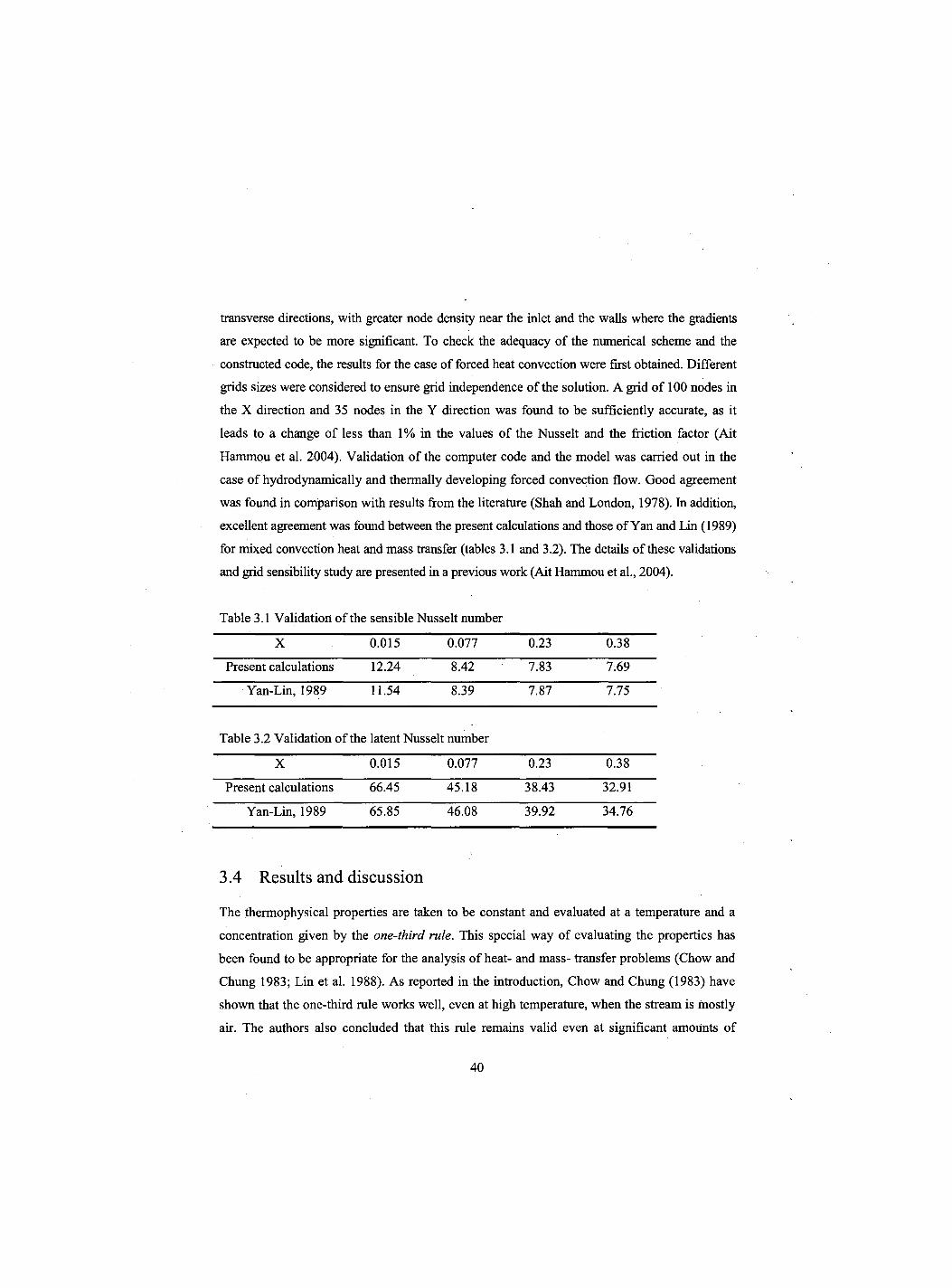
transverse directions, with greater node density near the inlet and the walls where the gradients
are expected to be more significant. To check the adequacy of the numerical scheme and the
constructed code, the results for the case of forced heat convection were first obtained. Different
grids sizes were considered to ensure grid independence of the solution. A grid of 100 nodes in
the X direction and 35 nodes in the Y direction was found to be sufficiently accurate, as it
leads to a change of less than 1% in the values of the Nusselt and the friction factor (Ait
Hammou et al. 2004). Validation of the computer code and the model was carried out in the
case of hydrodynamically and thermally developing forced convection flow. Good agreement
was found in comparison with results from the literature (Shah and London, 1978). In addition,
excellent agreement was found between the present calculations and those of Yan and Lin (1989)
for mixed convection heat and mass transfer (tables 3.1 and 3.2). The details of these validations
and grid sensibility study are presented in a previous work (Ait Hammou et al., 2004).
Table 3.1 Validation of the sensible Nusselt number
X 0.015 0.077 0.23 0.38
Present calculations 12.24 8.42 7.83 7.69
Yan-Lin, 1989 11.54 8.39 7.87 7.75
Table 3.2 Validation of the latent Nusselt number
X 0.015 0.077 0.23 0.38
Present calculations 66.45 45.18 38.43 32.91
Yan-Lin, 1989 65.85 46.08 39.92 34.76
3.4 Results and discussion
The thermophysical properties are taken to be constant and evaluated at a temperature and a
concentration given by the one-third rule. This special way of evaluating the properties has
been found to be appropriate for the analysis of heat- and mass- transfer problems (Chow and
Chung 1983; Lin et al. 1988). As reported in the introduction, Chow and Chung (1983) have
shown that the one-third rule works well, even at high temperature, when the stream is mostly
air. The authors also concluded that this rule remains valid even at significant amounts of
40
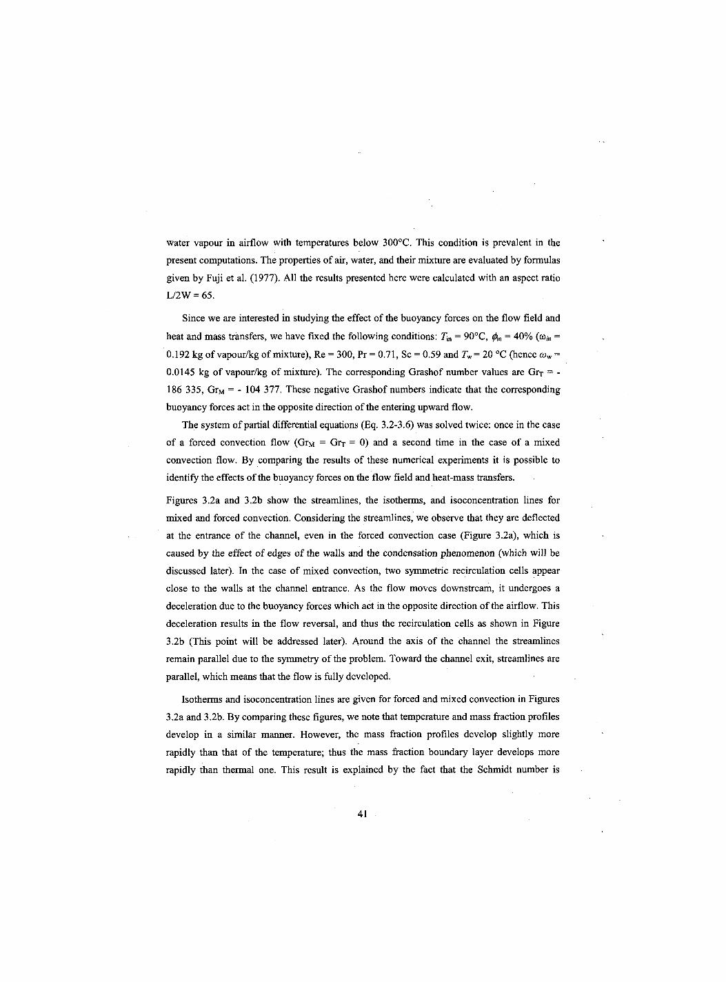
water vapour in airflow with temperatures below 300°C. This condition is prevalent in the
present computations. The properties of air, water, and their mixture are evaluated by formulas
given by Fuji et al. (1977). All the results presented here were calculated with an aspect ratio
L/2W = 65.
Since we are interested in studying the effect of the buoyancy forces on the flow field and
heat and mass transfers, we have fixed the following conditions: Tm = 90°C, = 40% (co,n =
0.192 kg of vapour/kg of mixture), Re = 300, Pr = 0.71, Sc = 0.59 and r w = 20 °C (hence cow =
0.0145 kg of vapour/kg of mixture). The corresponding Grashof number values are Grr = -
186 335, GrM = - 104 377. These negative Grashof numbers indicate that the corresponding
buoyancy forces act in the opposite direction of the entering upward flow.
The system of partial differential equations (Eq. 3.2-3.6) was solved twice: once in the case
of a forced convection flow (GrM = Grx = 0) and a second time in the case of a mixed
convection flow. By comparing the results of these numerical experiments it is possible to
identify the effects of the buoyancy forces on the flow field and heat-mass transfers.
Figures 3.2a and 3.2b show the streamlines, the isotherms, and isoconcentration lines for
mixed and forced convection. Considering the streamlines, we observe that they are deflected
at the entrance of the channel, even in the forced convection case (Figure 3.2a), which is
caused by the effect of edges of the walls and the condensation phenomenon (which will be
discussed later). In the case of mixed convection, two symmetric recirculation cells appear
close to the walls at the channel entrance. As the flow moves downstream, it undergoes a
deceleration due to the buoyancy forces which act in the opposite direction of the airflow. This
deceleration results in the flow reversal, and thus the recirculation cells as shown in Figure
3.2b (This point will be addressed later). Around the axis of the channel the streamlines
remain parallel due to the symmetry of the problem. Toward the channel exit, streamlines are
parallel, which means that the flow is fully developed.
Isotherms and isoconcentration lines are given for forced and mixed convection in Figures
3.2a and 3.2b. By comparing these figures, we note that temperature and mass fraction profiles
develop in a similar manner. However, the mass fraction profiles develop slightly more
rapidly than that of the temperature; thus the mass fraction boundary layer develops more
rapidly than thermal one. This result is explained by the fact that the Schmidt number is
41
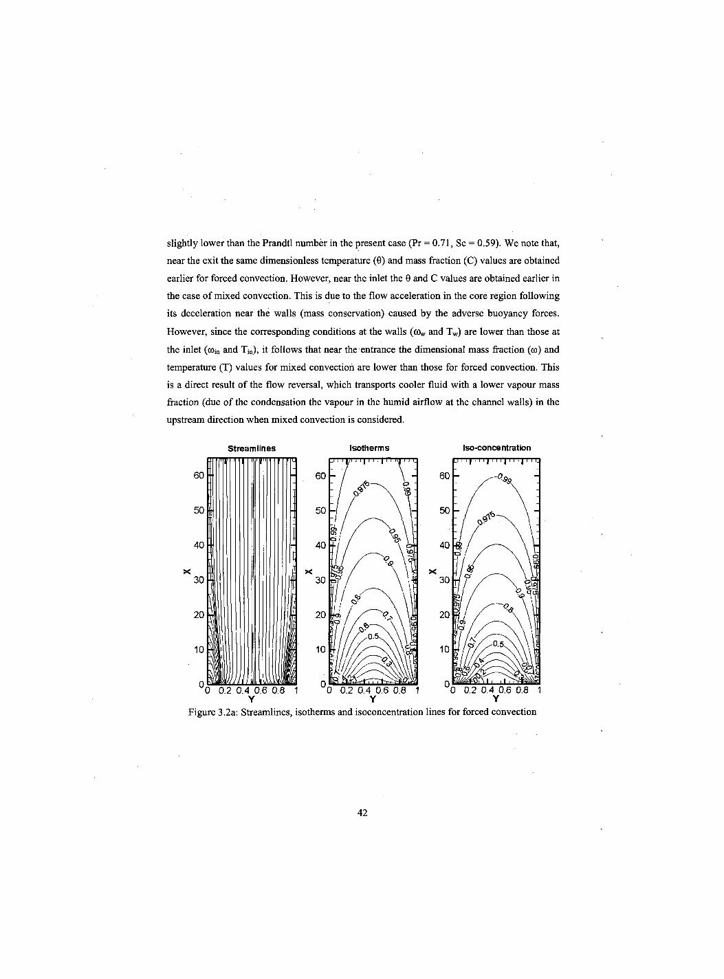
slightly lower than the Prandtl number in the present case (Pr = 0.71, Sc = 0.59). We note that,
near the exit the same dimensionless temperature (0) and mass fraction (C) values are obtained
earlier for forced convection. However, near the inlet the 0 and C values are obtained earlier in
the case of mixed convection. This is due to the flow acceleration in the core region following
its deceleration near the walls (mass conservation) caused by the adverse buoyancy forces.
However, since the corresponding conditions at the walls (ov and Tw) are lower than those at
the inlet (<»jn and Tjn) , it follows that near the entrance the dimensional mass fraction («) and
temperature (T) values for mixed convection are lower than those for forced convection. This
is a direct result of the flow reversal, which transports cooler fluid with a lower vapour mass
fraction (due of the condensation the vapour in the humid airflow at the channel walls) in the
upstream direction when mixed convection is considered.
Streamlines Isotherms Iso-concentration
Figure 3.2a: Streamlines, isotherms and isoconcentration lines for forced convection
42
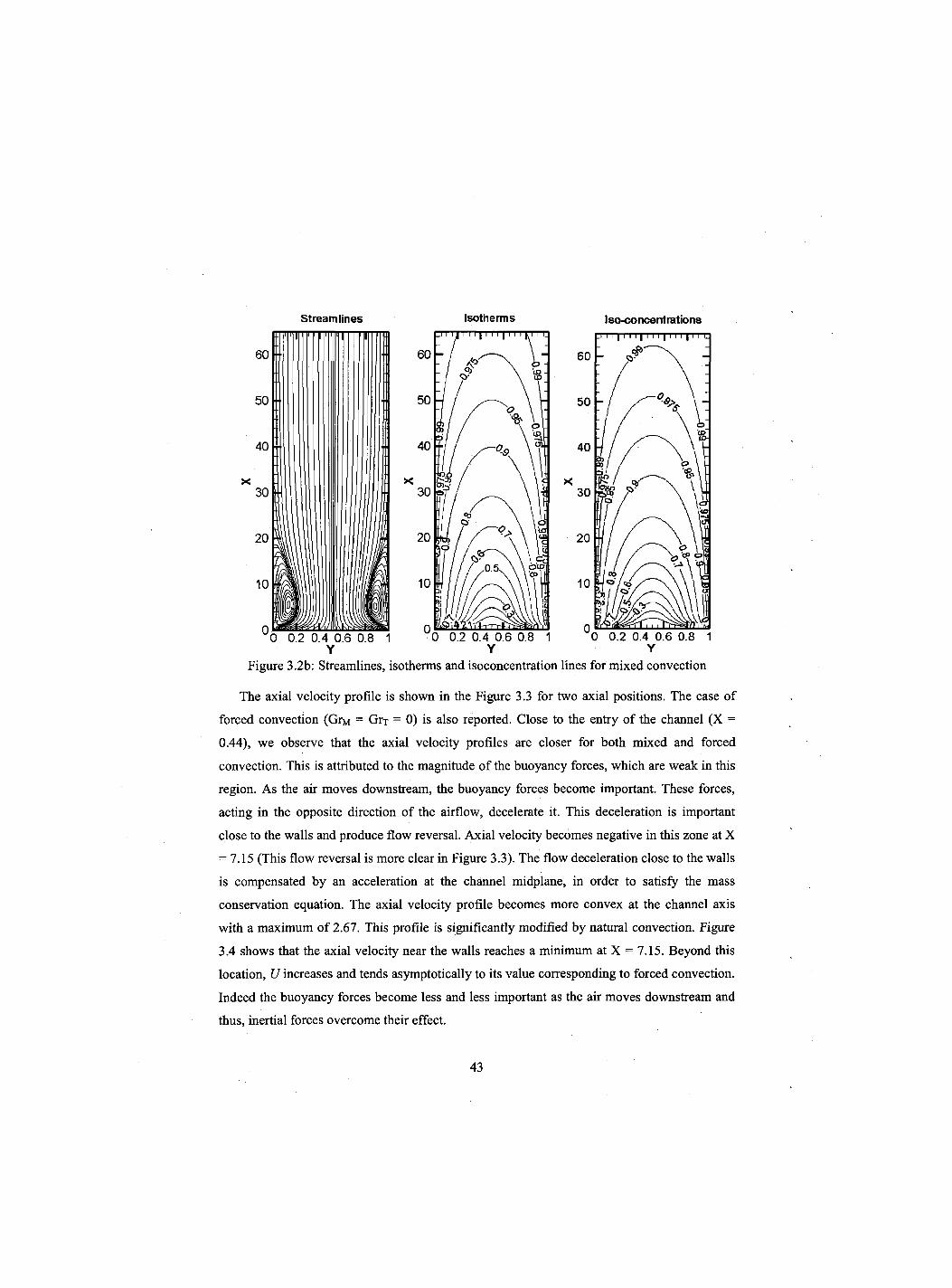
Streamlines Isotherms Iso-conceritrations
Figure 3.2b: Streamlines, isotherms and isoconcentration lines for mixed convection
The axial velocity profile is shown in the Figure 3.3 for two axial positions. The case of
forced convection (GrM = Grr = 0) is also reported. Close to the entry of the channel (X =
0.44), we observe that the axial velocity profiles are closer for both mixed and forced
convection. This is attributed to the magnitude of the buoyancy forces, which are weak in this
region. As the air moves downstream, the buoyancy forces become important. These forces,
acting in the opposite direction of the airflow, decelerate it. This deceleration is important
close to the walls and produce flow reversal. Axial velocity becomes negative in this zone at X
= 7.15 (This flow reversal is more clear in Figure 3.3). The flow deceleration close to the walls
is compensated by an acceleration at the channel midplane, in order to satisfy the mass
conservation equation. The axial velocity profile becomes more convex at the channel axis
with a maximum of 2.67. This profile is significantly modified by natural convection. Figure
3.4 shows that the axial velocity near the walls reaches a minimum at X = 7.15. Beyond this
location, LJ increases and tends asymptotically to its value corresponding to forced convection.
Indeed the buoyancy forces become less and less important as the air moves downstream and
thus, inertial forces overcome their effect.
43
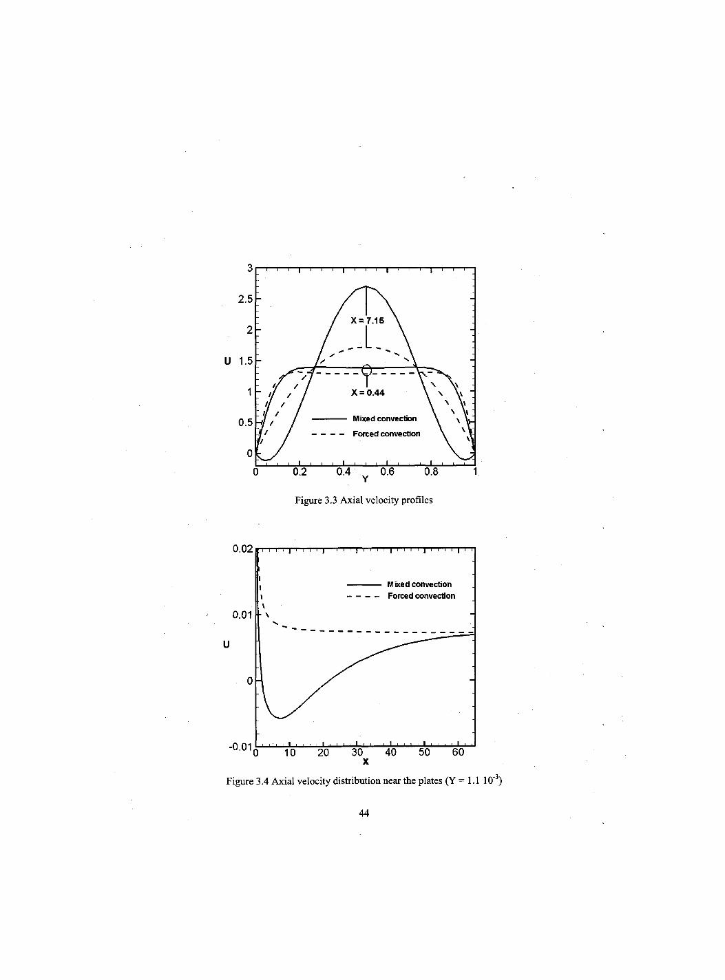
Figure 3.3 Axial velocity profiles
Figure 3.4 Axial velocity distribution near the plates (Y = 1.1 10"3)
44
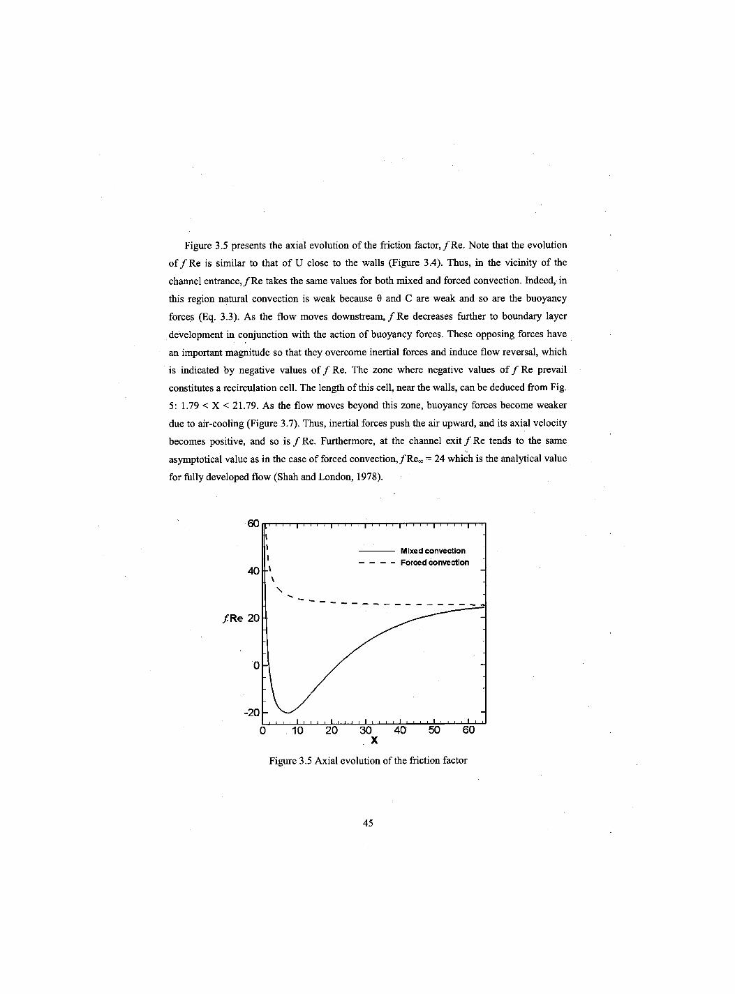
Figure 3.5 presents the axial evolution of the friction factor,/Re. Note that the evolution
of / R e is similar to that of U close to the walls (Figure 3.4). Thus, in the vicinity of the
channel entrance,/Re takes the same values for both mixed and forced convection. Indeed, in
this region natural convection is weak because 0 and C are weak and so are the buoyancy
forces (Eq. 3.3). As the flow moves downstream, / R e decreases further to boundary layer
development in conjunction with the action of buoyancy forces. These opposing forces have
an important magnitude so that they overcome inertial forces and induce flow reversal, which
is indicated by negative values of / Re. The zone where negative values of / Re prevail
constitutes a recirculation cell. The length of this cell, near the walls, can be deduced from Fig.
5: 1.79 < X < 21.79. As the flow moves beyond this zone, buoyancy forces become weaker
due to air-cooling (Figure 3.7). Thus, inertial forces push the air upward, and its axial velocity
becomes positive, and so is / Re. Furthermore, at the channel exit / Re tends to the same
asymptotical value as in the case of forced convection,/Re«, = 24 which is the analytical value
for fully developed flow (Shah and London, 1978).
60 i—| i i i i | i—i—i—i | i i i i | i i i i | i—i i i | i i
Mixed convection Forced convection
40 \
\
f . Re 20
- 2 0
0
_J_I I I I ' ' ' L_LJ L_l I I I I 1—1 I I—I I I I I—L_l—I—I—I 0 10 20 30 40 50 60
X
Figure 3.5 Axial evolution of the friction factor
45
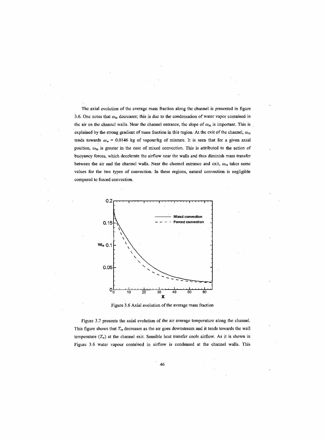
The axial evolution of the average mass fraction along the channel is presented in figure
3.6. One notes that a>m decreases; this is due to the condensation of water vapor contained in
the air on the channel walls. Near the channel entrance, the slope of com is important. This is
explained by the strong gradient of mass fraction in this region. At the exit of the channel, com
tends towards cow = 0.0146 kg of vapour/kg of mixture. It is seen that for a given axial
position, cym is greater in the case of mixed convection. This is attributed to the action of
buoyancy forces, which decelerate the airflow near the walls and thus diminish mass transfer
between the air and the channel walls. Near the channel entrance and exit, com takes same
values for the two types of convection. In these regions, natural convection is negligible
compared to forced convection.
Figure 3.6 Axial evolution of the average mass fraction
Figure 3.7 presents the axial evolution of the air average temperature along the channel.
This figure shows that Tm decreases as the air goes downstream and it tends towards the wall
temperature (rw) at the channel exit. Sensible heat transfer cools airflow. As it is shown in
Figure 3.6 water vapour contained in airflow is condensed at the channel walls. This
46
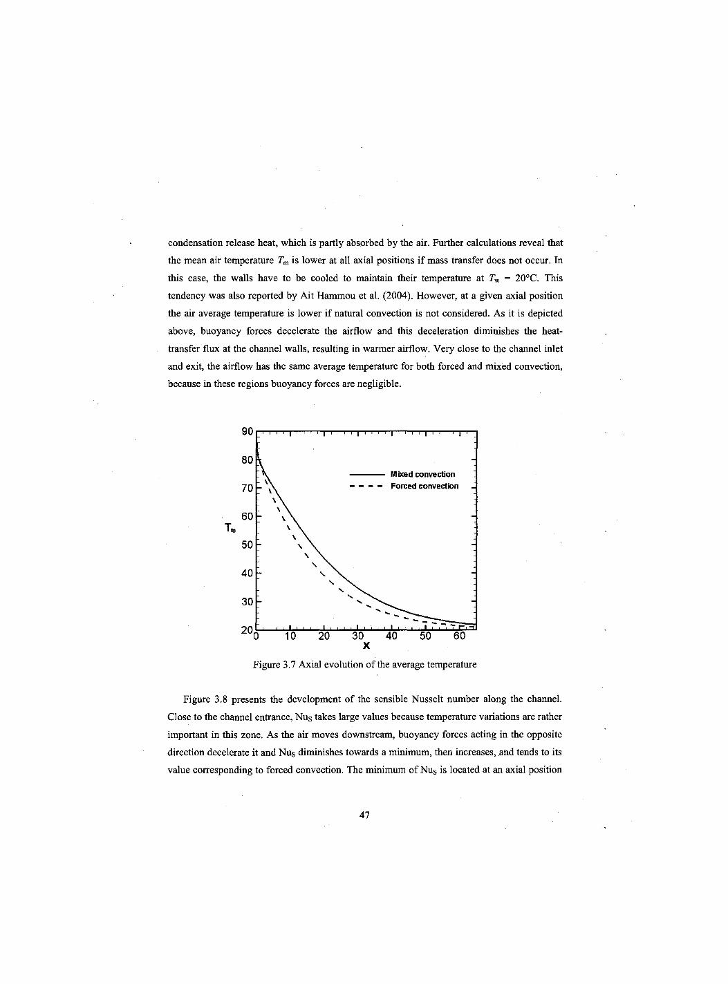
condensation release heat, which is partly absorbed by the air. Further calculations reveal that
the mean air temperature Tm is lower at all axial positions if mass transfer does not occur. In
this case, the walls have to be cooled to maintain their temperature at Tw = 20°C. This
tendency was also reported by Ait Hammou et al. (2004). However, at a given axial position
the air average temperature is lower if natural convection is not considered. As it is depicted
above, buoyancy forces decelerate the airflow and this deceleration diminishes the heat-
transfer flux at the channel walls, resulting in warmer airflow. Very close to the channel inlet
and exit, the airflow has the same average temperature for both forced and mixed convection,
because in these regions buoyancy forces are negligible.
Figure 3.7 Axial evolution of the average temperature
Figure 3.8 presents the development of the sensible Nusselt number along the channel.
Close to the channel entrance, Nus takes large values because temperature variations are rather
important in this zone. As the air moves downstream, buoyancy forces acting in the opposite
direction decelerate it and Nus diminishes towards a minimum, then increases, and tends to its
value corresponding to forced convection. The minimum of Nus is located at an axial position
47
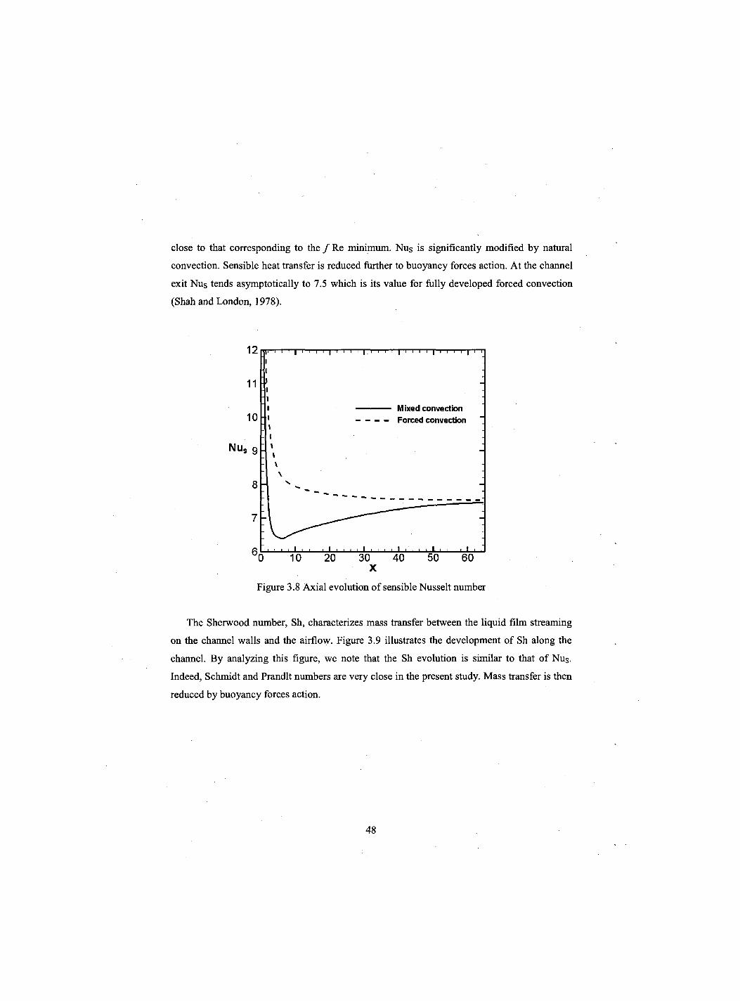
close to that corresponding to the / R e minimum. Nus is significantly modified by natural
convection. Sensible heat transfer is reduced further to buoyancy forces action. At the channel
exit Nus tends asymptotically to 7.5 which is its value for fully developed forced convection
(Shah and London, 1978).
Figure 3.8 Axial evolution of sensible Nusselt number
The Sherwood number, Sh, characterizes mass transfer between the liquid film streaming
on the channel walls and the airflow. Figure 3.9 illustrates the development of Sh along the
channel. By analyzing this figure, we note that the Sh evolution is similar to that of Nus.
Indeed, Schmidt and Prandlt numbers are very close in the present study. Mass transfer is then
reduced by buoyancy forces action.
48
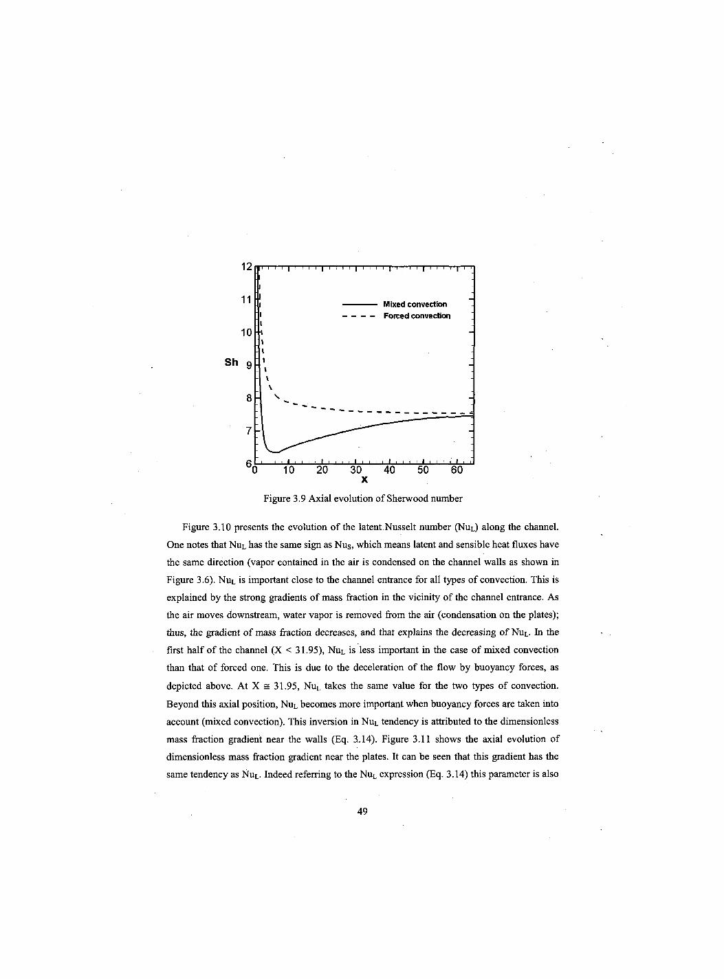
Figure 3.9 Axial evolution of Sherwood number
Figure 3.10 presents the evolution of the latent Nusselt number (NUL) along the channel.
One notes that Nul has the same sign as Nus, which means latent and sensible heat fluxes have
the same direction (vapor contained in the air is condensed on the channel walls as shown in
Figure 3.6). Nul is important close to the channel entrance for all types of convection. This is
explained by the strong gradients of mass fraction in the vicinity of the channel entrance. As
the air moves downstream, water vapor is removed from the air (condensation on the plates);
thus, the gradient of mass fraction decreases, and that explains the decreasing of Nul. In the
first half of the channel (X < 31.95), NUL is less important in the case of mixed convection
than that of forced one. This is due to the deceleration of the flow by buoyancy forces, as
depicted above. At X = 31.95, NuL takes the same value for the two types of convection.
Beyond this axial position, NUL becomes more important when buoyancy forces are taken into
account (mixed convection). This inversion in Nul tendency is attributed to the dimensionless
mass fraction gradient near the walls (Eq. 3.14). Figure 3.11 shows the axial evolution of
dimensionless mass fraction gradient near the plates. It can be seen that this gradient has the
same tendency as Nul. Indeed referring to the Nul expression (Eq. 3.14) this parameter is also
49
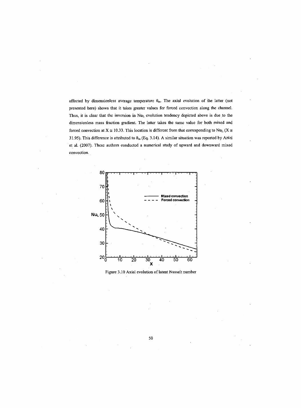
affected by dimensionless average temperature 0m. The axial evolution of the latter (not
presented here) shows that it takes greater values for forced convection along the channel.
Thus, it is clear that the inversion in NUL evolution tendency depicted above is due to the
dimensionless mass fraction gradient. The latter takes the same value for both mixed and
forced convection at X = 10.33. This location is different from that corresponding to NuL (X =
31.95). This difference is attributed to 0m (Eq. 3.14). A similar situation was reported by Azizi
et al. (2007). These authors conducted a numerical study of upward and downward mixed
convection.
80 iii i i i | i i i i | i i i i | i i i i | i i i i i i i i i |
7 0 ' !
60 Mixed convection Forced convection
Nu l 50
40
30
i i i i i i i , i i i 40 50 60
X
Figure 3.10 Axial evolution of latent Nusselt number
50
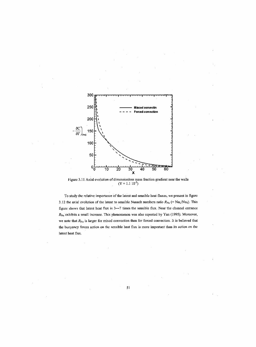
Figure 3.11 Axial evolution of dimensionless mass fraction gradient near the walls (Y = 1.1 103)
To study the relative importance of the latent and sensible heat fluxes, we present in figure
3.12 the axial evolution of the latent to sensible Nusselt numbers ratio (= NUL/NUS) . This
figure shows that latent heat flux is 3—7 times the sensible flux. Near the channel entrance
i?Nu exhibits a small increase. This phenomenon was also reported by Yan (1995). Moreover,
we note that i?Nu is larger for mixed convection than for forced convection. It is believed that
the buoyancy forces action on the sensible heat flux is more important than its action on the
latent heat flux.
51

X
Figure 3.12 Axial evolution of latent Nusselt to sensible Nusselt numbers ratio
3.5 Conclusion
Combined effects of thermal and mass diffusion buoyancy forces on an upward laminar forced
convection in a vertical parallel-plate channel were analyzed numerically. The plates were
isothermal and wetted by a thin liquid water film. Results show that buoyancy forces
decelerate the flow close to the plates and induce a flow reversal. Thus, these forces reduce
heat and mass transfer. The sensible heat transfer cools airflow while it is slightly heated by
the latent heat flux, which results from the water vapor condensation on the plates. In the first
half of the channel, the latent Nusselt number is less important if natural convection is
considered. This tendency is inversed in the second half of the channel. However, the latent
heat flux is always 3—7 times the sensible flux. Furthermore, in present computations, the
zero film thickness assumption may not be appropriate as condensation increases this thickness.
This point is under consideration.
52
CHAPITRE 4
Auteurs et affiliation: O. OULAID: Etudiant au doctorat, Universite de Sherbrooke, Faeulte de Genie, Departement de Genie Mecanique en cotutelle avec l'Universite Cadi Ayyad, Faeulte des Sciences-Semlalia, Departement de physique, Marrakech 40 001, Maroc.
B. BENHAMOU: Professeur, Universite Cadi Ayyad, Faeulte des sciences-Semlalia, Departement de physique, Marrakech 40 001, Maroc.
N. GALANIS: Professeur titulaire, Universite de Sherbrooke, Faeulte de Genie, Departement de Genie Mecanique.
Date d'acceptation : 14 avril 2010 r
Etat de l'acceptation : in press
Revue: International Journal of Heat and Fluid Flow
Reference: Oulaid, O. Benhamou, B. and Galanis, N. (2010). "Flow reversal in combined laminar mixed convection heat and mass transfer with phase change in a vertical
channel", International Journal of Heat and Fluid Flow, Vol. 31, pp. 711-721,
Titre fran9ais: Renversement d'ecoulement en convection mixte laminaire d'origine thermique et massique dans canal vertical.
Flow reversal in combined laminar mixed convection heat and mass transfer with phase change in a vertical channel
53
Resume:
Le present article est une etude numeriquement des effets des forces d'Archimede sur
l'ecoulement laminaire d'air humide dans un canal vertical. Ce canal est forme par deux
plaques planes paralleles. Les faces internes de ces plaques sont mouillees avec un film d'eau
et imposees a une temperature constante inferieure a celle de l'air a l'entree du canal. Les
resultats numeriques de cette etude montrent que ces forces ont un effet important sur les
champs hydrodynamique, thermique et massique. Ainsi ces forces causent le renversement
d'ecoulement pres des parois a l'entree du canal. Nous avons montre que le transfert par
chaleur latente est important compare a celui par chaleur sensible seulement si le gradient de
concentration est important. En fin les conditions d'existence du renversement sont presentees
par des abaques ainsi que des expressions analytiques. Ces abaques donnent le nombre de
Grashof thermique critique en fonction du nombre de Reynolds pour differentes valeurs du
nombre de Grashof massique et differents rapport de forme.
Mots cles: Renversement d'ecoulement, Convection mixte, Canal vertical, Transfert de chaleur et de masse, Changement de phase, Carte de renversement.
54
Abstract
This paper, deals with a numerical study of the effects of buoyancy forces on an upward,
steady state, laminar flow of humid air in a vertical parallel-plate channel. The plates are
wetted by a thin liquid water film and maintained at a constant temperature which is lower
than that of the air entering the channel. A 2D fully elliptical model, associated with the
Boussinesq assumption, is used to take into account axial diffusion. The solution of this
mathematical model is based on the finite volume method and the velocity-pressure coupling
is handled by the SIMPLER algorithm. Numerical results show that buoyancy forces have a
significant effect on the hydrodynamic, thermal and mass fraction fields. Additionally, these
forces induce flow reversal for high air temperatures and mass fractions at the channel
entrance. It is established that heat transfer associated with phase change is, sometimes, more
significant than sensible heat transfer. Furthermore, this importance depends on the mass
fraction gradient. The conditions for the existence of flow reversal are presented in charts and
analytical expressions specifying the critical thermal Grashof number as a function of the
Reynolds number for different values of the solutal Grashof number and different aspect ratios
of the channel.
Keywords: Flow reversal, Mixed convection, Vertical channel, Heat and mass transfer, Phase change, Flow reversal chart.
55
4.1 Introduction
Simultaneous heat and mass transfer with phase change is present in many natural and
engineering processes, such as human transpiration, desalination, refrigeration and air
conditioning. Many studies were conducted during the last decades to investigate the
combined effects of thermal and mass buoyancy forces. Lin et al., 1988 analysed the
combined buoyancy effects of thermal and mass diffusion on laminar forced convection heat
transfer in a vertical tube. Their results show that the effects of these forces are important for
small Reynolds numbers and high inlet temperatures. Also, heat transfer is dominated by the
transport of latent heat due to the evaporation of the liquid film. Evaporative cooling of a
liquid film through interfacial heat and mass transfer in a vertical channel was studied
experimentally and numerically by Yan et al., 1991 and Yan and Lin, 1991. Two parallel and
adiabatic plates form the channel. A liquid film of ethanol streams along the plates with a
temperature, which is higher than that of the downward airflow at the entrance. Their results
showed that the influence of the evaporative latent heat transfer on the cooling of the liquid
film depends largely on the inlet liquid film temperature and the inlet liquid mass flow rate.
Also, their numerical results agree well with the experimental data. Debbissi et al., 2001
studied the evaporation of water by free convection in a vertical channel including the effects
of wall radiative properties. A liquid water film streams along one of the plates whereas the
other is dry. Both of the plates are heated by a constant uniform heat flux. Their results show
that the evaporative cooling at the liquid-air interface disturbs considerably the velocity and
temperature profiles in particular near the exit section of the channel. Moreover, the interfacial
heat and mass transfer at the humid plate is dominated by the water vaporization.
Flow reversal was studied analytically for fully developed flow with coupled heat and mass
transfer by Salah El-Din, 1992 and Boulama and Galanis, 2004. These authors presented the
criteria of occurrence of this phenomenon. These studies are some of the rare ones concerning
flow reversal in combined mixed convection heat and mass transfer. On the other hand, flow
reversal was extensively studied in thermal convection problems. For instance, Nguyen et al.,
2004 studied the flow reversal and the instability of a transient laminar thermal mixed
convection in a vertical tube subjected to a uniform time-dependent wall heat flux. The
problem was investigated numerically by using a full 3D-transient-model and Boussinesq's
56
assumption. Results show that the flow reversal depends primarily on the Grashof number.
Thus, for opposed-buoyancy, it occurs at the tube exit near the walls for Gr = 3.105, and at the
centreline for Grashof number around 106 in the case of assisted-buoyancy. Mixed convection
with flow reversal in the thermal entrance region of horizontal and vertical pipes was studied
numerically by Wang et al., 1994. Their results show that, for ascending flow in a vertical
pipe, flow reversal is observed at the pipe centre in the heating case (or near the wall in the
cooling case) at relatively high |Gr/Re| with constant Peclet number. The regime of flow
reversal has been identified for both heating and cooling cases in the Pe-|Gr/Re| coordinates
for a vertical pipe and in the Pe-Ra coordinates for heating in a horizontal pipe. Experimental
and numerical studies of thermal mixed convection with flow reversal in coaxial double-duct
heat exchangers have been carried out by Mare et al., 2008. Velocity vectors in a vertical heat
exchanger for parallel ascending flow of water under conditions of laminar mixed convection
have been determined experimentally using the particle image velocimetry technique. Their
results show that measured velocity distributions are in very good agreement with
corresponding numerical predictions and illustrate the simultaneous existence of flow reversal
in the tube and the annulus for both heating and cooling of the fluid in the tube. This situation
occurred for approximately equal low flow rates in the tube and annulus and temperature
differences at the inlet corresponding to a Richardson number approximately equal to one.
Flow under such conditions causes increased losses, may lead to instabilities and affects heat
transfer, they should therefore be avoided.
As far as developing flows with heat and mass transfer are concerned, studies on flow reversal
are rare [Azizi et al., 2007 and Laaroussi et al., 2009]. Indeed, the majority of the studies on
this problem adopted a parabolic model where axial diffusion of momentum, energy and
concentration is not taken into account. This model may not be appropriate for flows with low
Peclet number where axial diffusion is not negligible [Nesreddine et al., 1998]. In addition,
this model cannot predict certain physical phenomena such as the flow reversal if the
buoyancy forces are important [Faghri et al., 1980 and Salah El-Din, 2001].
Ait Hammou et al., 2004 have examined numerically the effects of simultaneous heat and
mass transfer on a downward laminar flow of humid air in an isothermal vertical channel with
wetted walls. By varying the inlet conditions of the humid air, cases of film evaporation and
vapour condensation were considered. On the other hand, it was demonstrated that thermal
57
and mass diffusion buoyancy forces have significant effects on flow characteristics. Flow
reversal was not detected for any of the cases under investigation. Recently, Azizi et al., 2007
studied numerically buoyancy effects on upward and downward laminar mixed convection
heat and mass transfer in a vertical channel. Flow reversal was predicted for upward flow with
high inlet temperature. More recently, flow reversal was investigated by Laaroussi et al., 2009.
These authors conducted a numerical study on laminar mixed convection in a vertical parallel-
plate channel with film evaporation. The plates are isothermal. Air-water and air-hexane
systems were considered. The airflow is downward and the liquid film is considered extremely
thin. The effects of both thermal and mass diffusion buoyancy forces are investigated. For
water films the latter is opposing and film evaporation produces a significant increase in axial
velocity at the core region due to the action of buoyancy forces. For large values of the
interfacial mass fraction, flow reversal may occur near the channel walls.
The principal motivation of the present study is to investigate the flow reversal in an upward
laminar mixed convection with phase change in a vertical parallel-plate channel. Specifically,
we analyse the effects of this phenomenon on heat and mass transfers, as well as the criteria of
its occurrence. To analyse this phenomenon the adopted model includes the axial diffusion
terms, thus, the equations are elliptical in all directions. Moreover, the conditions under
investigation correspond to those encountered in air humidifiers, humidification-
dehumidification desalination systems or evaporative air coolers where hot air is in direct
contact with cold water.
4.2 Description and Modeling of the problem
The physical problem is a vertical channel formed by two parallel plane plates (Figure 4.1). A
water film flows on the internal faces of these plates, which are maintained at a uniform
temperature Tw. An upward flow of ambient air enters at temperature Tj„, relative humidity
and uniform velocity Ujn. Steady state conditions are considered and the flow is assumed
laminar. Radiation heat transfer, the transfer of energy by inter-diffusion of species, viscous
dissipation and the work of the compressive forces are considered negligible. The secondary
effects of concentration gradient on the thermal diffusion (Dufour effect) and thermal gradient
on the mass diffusion (Soret effect) are neglected [Gebhart et Pera, 1971], Finally, the physical
58
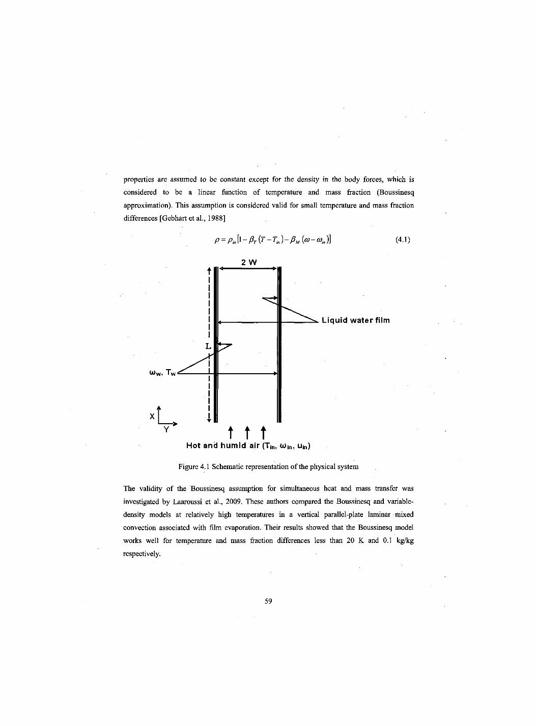
properties are assumed to be constant except for the density in the body forces, which is
considered to be a linear function of temperature and mass fraction (Boussinesq
approximation). This assumption is considered valid for small temperature and mass fraction
differences [Gebhart et al., 1988]
P = P^-PT{T-Tin)-PM{m-a>in)] (4.1)
2 W
Ww, T
Liquid water film
t t t Hot and humid air (T|„, coin, u in)
Figure 4.1 Schematic representation of the physical system
The validity of the Boussinesq assumption for simultaneous heat and mass transfer was
investigated by Laaroussi et al., 2009. These authors compared the Boussinesq and variable-
density models at relatively high temperatures in a vertical parallel-plate laminar mixed
convection associated with film evaporation. Their results showed that the Boussinesq model
works well for temperature and mass fraction differences less than 20 K and 0.1 kg/kg
respectively.
59
The liquid films are assumed to be thin So that they can be treated as a boundary condition. This
simplification allows us to handle only the conservation equations in the gas flow. The liquid film
is therefore assumed to be at the wall temperature. Yan, 1993 has stated that this assumption is
valid for small liquid mass flow rates. This assumption has been extensively used in the literature
[Lin et al., 1988, Laaroussi et al., 2009, Yan et al., 1990 and Yan, 1993].
Under these assumptions, the governing equations of the problem can be written in the following
non-dimensional form:
Continuity equation
Momentum equations
— + — = 0 ax aY
bx b y dP„ 2 ( b 2 u d2U dX ' Re{dX2 + BY2
(4.2)
+ -±-(Grr0 + GrMC) (4.3) /
b x a y b y Re
Re
F B2V B2V N
BX2 BY2 (4.4)
Energy equation
u f ^ f |= BX BY) RePr
' b 2 e b2e>
k b x 2 + b y 2 , (4.5)
Species conservation equation
b x b y ReSc ' B2C B2C
KBX2+ BY2 (4.6)
where
2W 2W um u, pm ufn in in r in in ,0 =
T-T T -T 1 W 1 in
and C = co„, - co„
The boundary conditions for the problem under consideration are
- At the inlet (X = 0): U = 1 and V = C = Q = 0
BU BV B6 BC - At the outlet (X = 1/y):
- At the walls (7 = 0 and Y =/):
= 0
bx bx bx bx U = 0,V = ±Ve, C = 9 = 7
(4.7)
(4.8)
(4.9)
60
where the non-dimensional transverse velocity at the interface is [Burmeister, 1993]
- 2 (,mw-G) i n)(dC^ V' =
Re Sc (l -a>w) (4.10)
'y=o
The mass fraction at the wall C0w corresponding to the saturation conditions at Tw, is
calculated by assuming that air-vapour mixture is an ideal gas mixture, and its expression is given
by:
M„
+ 1 (4.11)
Ma Psa,{Tw)
Heat transfer between the wet walls and the humid air is the sum of a sensible and a latent
component flux
joDhfg da) q = is +qL = dy y=0 1 -eow dy y=0
Therefore, the Nusselt number is
h Dh _ q"TDh NUT = — . . k k(Tw-Tm)
= Nus + NUL
where
Nu c - 2 de 1 - 0 . dY y = o
Nu p D h * ( ^ - ^ J 2 dC L k(i-em) (i-coj (:Tw-rin)dY Y= 0
The Sherwood number characterizes mass transfer at the air-liquid interface
S h _ KdH _ m Dh D p{Q}w-Q)m) D
The interfacial liquid and vapour mass fluxes are given by
»»" =pLVL=<°wPVe-pD dm
¥ y = 0
The Sherwood number is therefore,
(4.12)
(4.13)
(4.14)
(4.15)
(4.16a)
(4.16b)
61
sh = -D, Bet) (1 -mwXo)w-6)m) dy
(4.16c) o
Since ®w is very small in our problem (cow < 0.023) this expression can be simplified as
follows:
Sh = - -Dh Bco (eow-a)m) By
The corresponding non-dimensional form is
- 2 BC
y=0
Sh = (i -cm) b y Y= 0
while the friction factor is
/ .Re = 4 BU] b y jy=0
The dimensionless bulk temperature is defined as follows:
0m=—(u0dY m u A
and
C = — [uCdY
(4.16d)
(4.16e)
(4.17)
(4.18)
(4.19)
4.3 Numerical method
The coupled PDEs are solved by the finite volume method and the velocity-pressure coupling
is treated by the SIMPLER algorithm [Patankar, 1980], Convergence of this iterative procedure
is declared when the relative variation of any dependent variable is less than 10"4 and if the mass
source residual falls below 10"6. The grid is non-uniform in both the streamwise and transverse
directions with greater node density near the inlet and the walls where the gradients are expected
to be more significant. Different grids (100 x 35, 200 x 70, and 400 x 140) were considered to
establish the grid independence. The details of this grid sensibility test are provided in a
previous work [Ait Hammou et al., 2004] and show that the values of Nus and/Re differ by
less than 1%. A grid with 100 nodes in the axial direction and 35 nodes in the transverse one is
62
therefore adopted in the present study. The computer code was validated [Ait Hammou et al.,
2004] with the results available from the literature [Shah et London, 1978] for thermal
developing forced convection. In addition, good agreement was found between our
calculations and those from the numerical study of Yan et Lin, 1989 for mixed convection heat
and mass transfer (Tables 4:1 and 4.2). Finally, Figure 4.2 shows a comparison of velocity
profiles calculated by Laaroussi et al., 2009 with the variable density model and our results
using the Boussinesq approximation. The difference between corresponding results is less than
4%. All these comparisons validate the model including the Boussinesq approximation and the
numerical procedure used for its solution.
Table 4.1 Validation of the sensible Nusselt number
X 0.015 0.077 0.23 0.38
Present calculations 12.24 8.42 7.83 7.69
Yan-Lin, 1989 11.54 8.39 7.87 7.75
Table 4.2 Validation of the latent Nusselt number
X 0.015 0.077 0.23 0.38
Present calculations 66.45 45.18 38.43 32.91
Yan-Lin, 1989 65.85 46.08 39.92 34.76
63
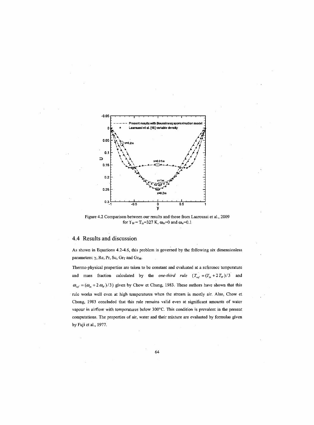
-0.05
O r * Laaroussi et al. [15] variable density .
0.05 - ]a V * yV~ : / / ; : : / / / :
0 1 " \ A \ / / ; " 3 \ i i jL / a
a \ \ . x=0.01m / f ' 0 1 5 r
0 2 • V „ 0.25 -
x=0.2m I
n 3 i i i i I i i i i I i i i i I i i i i -1 -0.5 0 0.5 1
y Figure 4.2 Comparison between our results and those from Laaroussi et al., 2009
for T w = Tin=327 K, tOin=0 and (Ow=0.1
4.4 Results and discussion
As shown in Equations 4.2-4.6, this problem is governed by the following six dimensionless
parameters: y, Re, Pr, Sc, Grp and GrM.
Thermo-physical properties are taken to be constant and evaluated at a reference temperature
and mass fraction calculated by the one-third rule (Tref = (Tin +2Tw)/3 and
a>ref ={cojn +2*%)/3) given by Chow et Chung, 1983. These authors have shown that this
rule works well even at high temperatures when the stream is mostly air. Also, Chow et
Chung, 1983 concluded that this rule remains valid even at significant amounts of water
vapour in airflow with temperatures below 300°C. This condition is prevalent in the present
computations. The properties of air, water and their mixture are evaluated by formulas given
by Fuji etal., 1977.
i I i i i i I i i i i i i i i i Present results with Boussinesq approximation model -
r Laaroussi et al. [15] variable density
* \ \ / j f ,2m / / . ' -A .'4 -
\ \ \ > / / \ \ \ / / /
\ * A £ / a a \ v x=0.01m / A j
\ \ ^ — A / it
J* \ i v w—4 M . x=1m \ A •
As,
x=0.2m
64
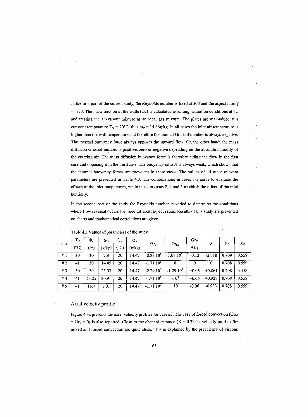
In the first part of the current study, the Reynolds number is fixed at 300 and the aspect ratio y
= 1/50. The mass fraction at the walls (tOw) is calculated assuming saturation conditions at Tw
and treating the air-vapour mixture as an ideal gas mixture. The plates are maintained at a
constant temperature Tw = 20°C; thus tOw = 14.66g/kg. In all cases the inlet air temperature is
higher than the wall temperature and therefore the thermal Grashof number is always negative.
The thermal buoyancy force always opposes the upward flow. On the other hand, the mass
diffusion Grashof number is positive, zero or negative depending on the absolute humidity of
the entering air. The mass diffusion buoyancy force is therefore aiding the flow in the first
case and opposing it in the third case. The buoyancy ratio N is always weak, which shows that
the thermal buoyancy forces are prevalent in these cases. The values of all other relevant
parameters are presented in Table 4.3. The combinations in cases 1-3 serve to evaluate the
effects of the inlet temperature, while those in cases 2, 4 and 5 establish the effect of the inlet
humidity.
In the second part of the study the Reynolds number is varied to determine the conditions
where flow reversal occurs for three different aspect ratios. Results of this study are presented
on charts and mathematical correlations are given.
Table 4.3 Values of parameters of the study
case Tin
(°C) (%)
Win
(g/kg)
Tw
(°C)
0>w
(g/kg)-Grx GrM
GrM
/Grj s Pr Sc
# 1 30 30 7.8 20 14.47 -0.88.10s 1.07.104 -0.12 -2.018 0.709 0.559
# 2 41 30 14.45 20 14.47 -1.71.10s 0 0 0 0.708 0.559
# 3 50 30 23.03 20 14.47 -2.29.10s -1.29.104 +0.06 +0.861 0.708 0.558
# 4 41 43.25 20.91 20 14.47 -1.71.10s -104 +0.06 +0.929 0.708 0.558
# 5 41 16.7 8.01 20 14.47 -1.71.10s +104 -0.06 -0.933 0.708 0.559
Axial velocity profile
Figure 4.3a presents the axial velocity profiles for case #3. The case of forced convection (GrM
= GrT = 0) is also reported. Close to the channel entrance (X = 0.3) the velocity profiles for
mixed and forced convection are quite close. This is explained by the prevalence of viscous
65
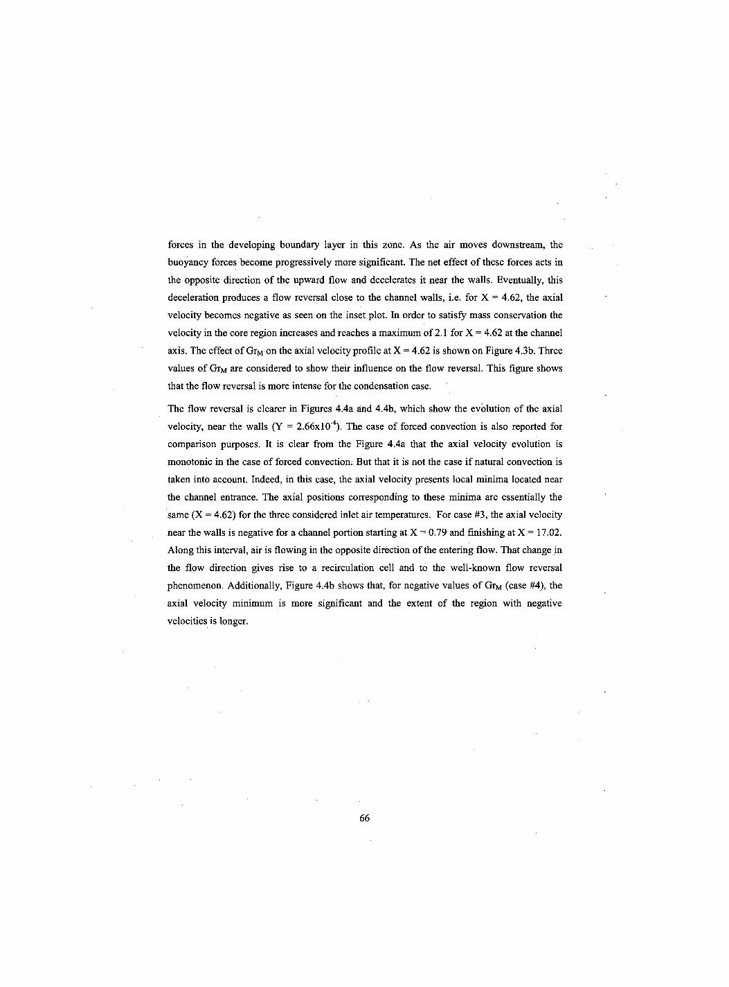
forces in the developing boundary layer in this zone. As the air moves downstream, the
buoyancy forces become progressively more significant. The net effect of these forces acts in
the opposite direction of the upward flow and decelerates it near the walls. Eventually, this
deceleration produces a flow reversal close to the channel walls, i.e. for X = 4.62, the axial
velocity becomes negative as seen on the inset plot. In order to satisfy mass conservation the
velocity in the core region increases and reaches a maximum of 2.1 for X = 4.62 at the channel
axis. The effect of GrM on the axial velocity profile at X = 4.62 is shown on Figure 4.3b. Three
values of GrM are considered to show their influence on the flow reversal. This figure shows
that the flow reversal is more intense for the condensation case.
The flow reversal is clearer in Figures 4.4a and 4.4b, which show the evolution of the axial
velocity, near the walls (Y = 2.66xl0"4). The case of forced convection is also reported for
comparison purposes. It is clear from the Figure 4.4a that the axial velocity evolution is
monotonic in the case of forced convection. But that it is not the case if natural convection is
taken into account. Indeed, in this case, the axial velocity presents local minima located near
the channel entrance. The axial positions corresponding to these minima are essentially the
same (X = 4.62) for the three considered inlet air temperatures. For case #3, the axial velocity
near the walls is negative for a channel portion starting at X = 0.79 and finishing at X = 17.02.
Along this interval, air is flowing in the opposite direction of the entering flow. That change in
the flow direction gives rise to a recirculation cell and to the well-known flow reversal
phenomenon. Additionally, Figure 4.4b shows that, for negative values of GrM (case #4), the
axial velocity minimum is more significant and the extent of the region with negative
velocities is longer.
66
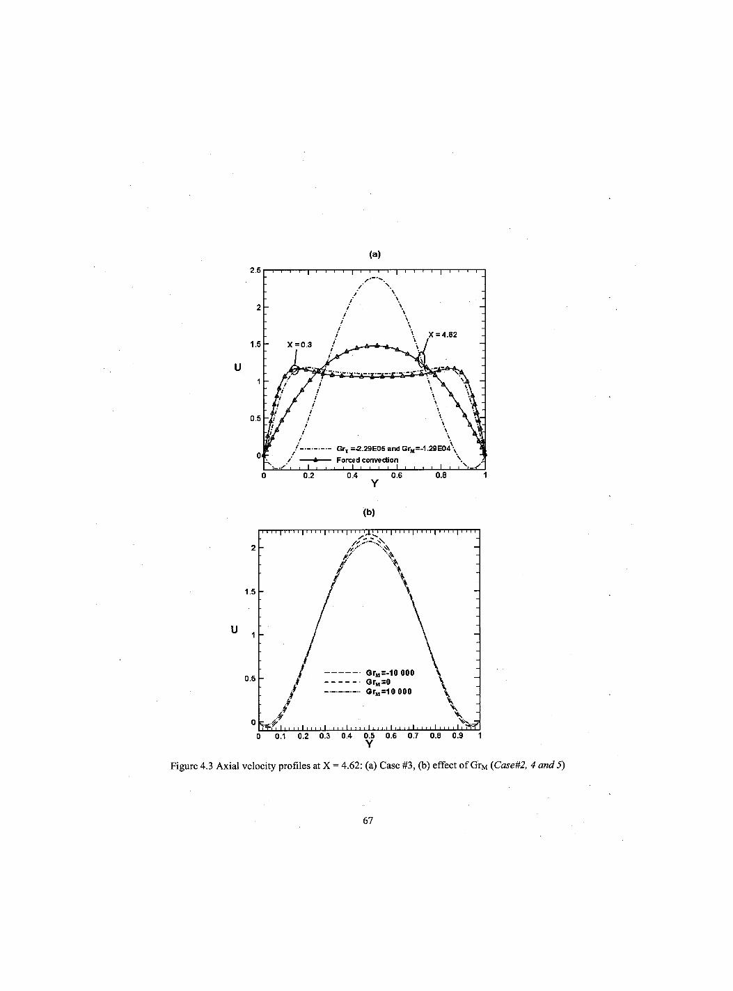
(a)
Y
(b)
Y
Figure 4.3 Axial velocity profiles at X = 4.62: (a) Case #3, (b) effect of GrM (Case#2, 4 and 5)
67
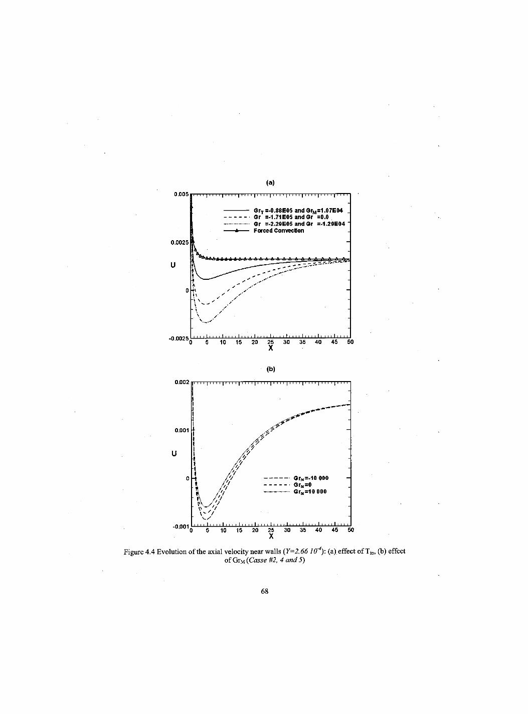
(a)
(b)
0.002
0.001
U
o
" 0 0 0 1 0 5 10 15 20 25 30 35 40 45 50 X
Figure 4.4 Evolution of the axial velocity near walls (Y=2.66 I f f 4 ) : (a) effect of Tin, (b) effect of GrM (Casse #2, 4 and 5)
68
|l II I | II I I | I I! I | II I I | I I I I | II II | I I I I | I I I I | I I I I | I
i I i ! ..-91
1 I. 1 //' ' J,' i y/f
-i / ' / GrM=-10 000 J / / GrM=0 \ / ' / GrM=10 000 i\ / / / I". / '/ \ /
' ' ' ' I' ' ' ' I ' ' ' ' 1 1 1 1 1 1 1 1 1 1 11 1 1 1 1 1 1 1 1 11 1 1 1 1 1 1 1
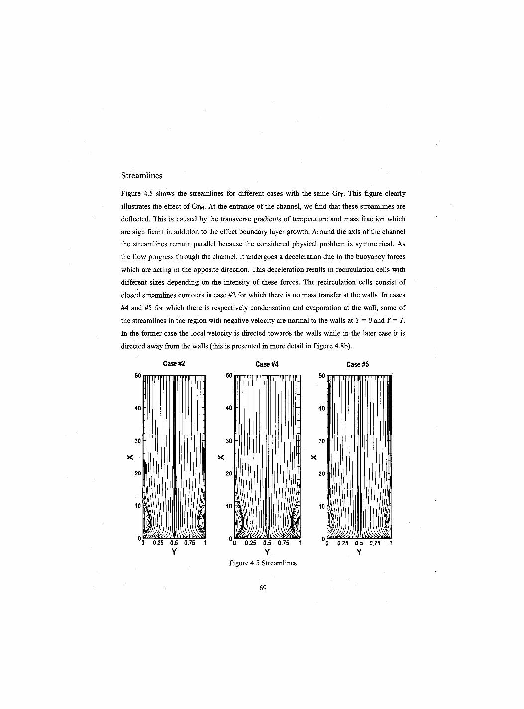
Streamlines
Figure 4.5 shows the streamlines for different cases with the same GrT. This figure clearly
illustrates the effect of GrM- At the entrance of the channel, we find that these streamlines are
deflected. This is caused by the transverse gradients of temperature and mass fraction which
are significant in addition to the effect boundary layer growth. Around the axis of the channel
the streamlines remain parallel because the considered physical problem is symmetrical. As
the flow progress through the channel, it undergoes a deceleration due to the buoyancy forces
which are acting in the opposite direction. This deceleration results in recirculation cells with
different sizes depending on the intensity of these forces. The recirculation cells consist of
closed streamlines contours in case #2 for which there is no mass transfer at the walls. In cases
#4 and #5 for which there is respectively condensation and evaporation at the wall, some of
the streamlines in the region with negative velocity are normal to the walls at Y = 0 and Y = 1.
In the former case the local velocity is directed towards the walls while in the later case it is
directed away from the walls (this is presented in more detail in Figure 4.8b).
Case #2
0 0.25 0.5 0.75 Y
0 0.25 0.5 0.75 1 Y
Figure 4.5 Streamlines
0 0.25 0.5 0.75 1 Y
69
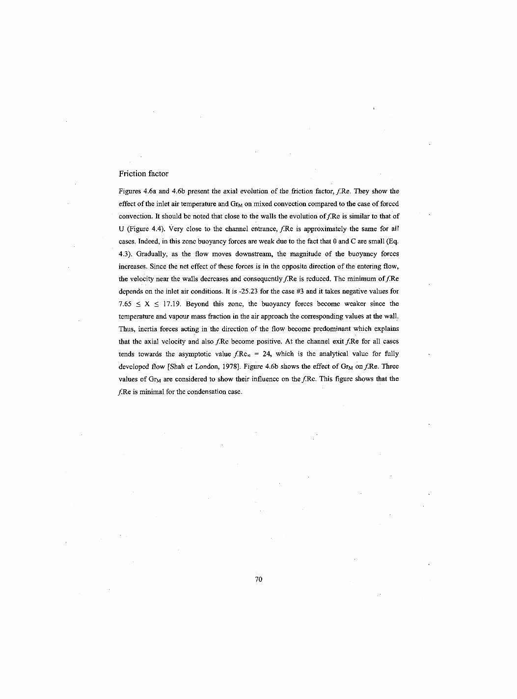
Friction factor
Figures 4.6a and 4.6b present the axial evolution of the friction factor, / R e . They show the
effect of the inlet air temperature and GrM on mixed convection compared to the case of forced
convection. It should be noted that close to the walls the evolution o f / R e is similar to that of
U (Figure 4.4). Very close to the channel entrance, / R e is approximately the same for all
cases. Indeed, in this zone buoyancy forces are weak due to the fact that 9 and C are small (Eq.
4.3). Gradually, as the flow moves downstream, the magnitude of the buoyancy forces
increases. Since the net effect of these forces is in the opposite direction of the entering flow,
the velocity near the walls decreases and consequently/Re is reduced. The minimum o f / R e
depends on the inlet air conditions. It is -25.23 for the case #3 and it takes negative values for
7.65 < X < 17.19. Beyond this zone, the buoyancy forces become weaker since the
temperature and vapour mass fraction in the air approach the corresponding values at the wall.
Thus, inertia forces acting in the direction of the flow become predominant which explains
that the axial velocity and also / R e become positive. At the channel exit / R e for all cases
tends towards the asymptotic value /Re*, = 24, which is the analytical value for fully
developed flow [Shah et London, 1978]. Figure 4.6b shows the effect of GrM on / R e . Three
values of GrM are considered to show their influence on the /Re . This figure shows that the
/ R e is minimal for the condensation case.
70
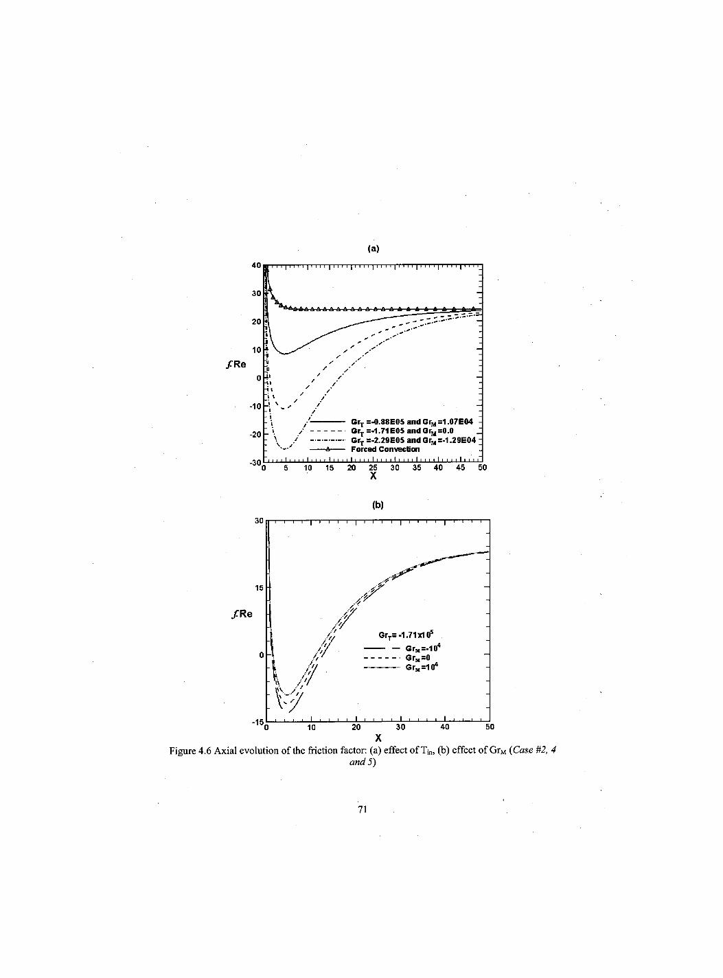
(a)
X
(b)
X Figure 4.6 Axial evolution of the friction factor: (a) effect of Tin, (b) effect of GrM (Case #2, 4
and 5)
71
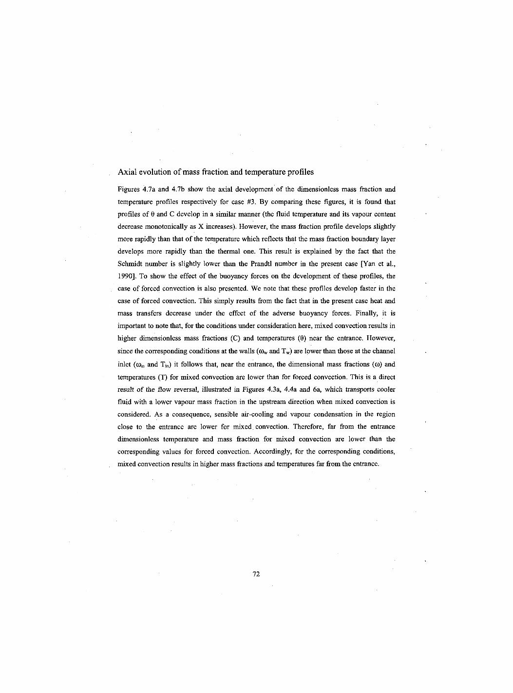
Axial evolution of mass fraction and temperature profiles
Figures 4.7a and 4.7b show the axial development of the dimensionless mass fraction and
temperature profiles respectively for case #3. By comparing these figures, it is found that
profiles of 0 and C develop in a similar manner (the fluid temperature and its vapour content
decrease monotonically as X increases). However, the mass fraction profile develops slightly
more rapidly than that of the temperature which reflects that the mass fraction boundary layer
develops more rapidly than the thermal one. This result is explained by the fact that the
Schmidt number is slightly lower than the Prandtl number in the present case [Yan et al.,
1990]. To show the effect of the buoyancy forces on the development of these profiles, the
case of forced convection is also presented. We note that these profiles develop faster in the
case of forced convection. This simply results from the fact that in the present case heat and
mass transfers decrease under the effect of the adverse buoyancy forces. Finally, it is
important to note that, for the conditions under consideration here, mixed convection results in
higher dimensionless mass fractions (C) and temperatures (0) near the entrance. However,
since the corresponding conditions at the walls (ov and Tw) are lower than those at the channel
inlet (com and Tjn) it follows that, near the entrance, the dimensional mass fractions (to) and
temperatures (T) for mixed convection are lower than for forced convection. This is a direct
result of the flow reversal, illustrated in Figures 4.3a, 4.4a and 6a, which transports cooler
fluid with a lower vapour mass fraction in the upstream direction when mixed convection is
considered. As a consequence, sensible air-cooling and vapour condensation in the region
close to the entrance are lower for mixed convection. Therefore, far from the entrance
dimensionless temperature and mass fraction for mixed convection are lower than the
corresponding values for forced convection. Accordingly, for the corresponding conditions,
mixed convection results in higher mass fractions and temperatures far from the entrance.
72
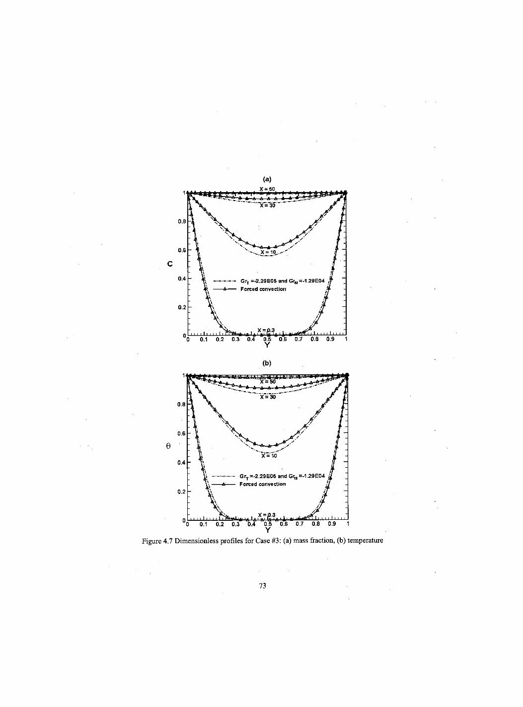
Y
(b)
Y Figure 4.7 Dimensionless profiles for Case #3: (a) mass fraction, (b) temperature
73
Axial evolution of transverse wall velocity
Figures 4.8a and 4.8b present the axial evolution of the dimensionless transverse vapour
velocity at the wall, Ve. We note that Ve is negative for case #3 (condensation case), positive
for case #1 (evaporation case) while it is null for case #2 (GrM - 0 when coin = (Dw). Positive
values of Ve are obtained for av > C0in and indicate an evaporation of the liquid film while
negative values are obtained for av < a>jn and indicate a condensation of the water vapour on
the walls. Ve = 0 means that there is no mass transfer between the airflow and the wall. Very
close to the channel entrance, Ve takes large values due to the large mass gradient. As the air
moves downstream, it is humidified or dehumidified and the mass fraction gradient becomes
lower. Therefore, Ve tends monotonically towards zero.
The case of forced convection for case #3 is also shown in Figure 4.8a for comparison
purposes. We note that near the entrance (X < 7.44) the absolute value of Ve is higher in the
case of forced convection while further downstream mixed convection results in greater
absolute values of Ve. As indicated by Eq. 4.10 this behaviour reflects the corresponding axial
variation of the absolute value of the dimensionless mass fraction gradient at the wall (see
Figure 4.9) which is higher for forced convection when X < 7.44 and for mixed convection
further downstream. This inversion occurs within the zone where flow reversal takes place
(see Figures 4.4a and 4.6a) and is caused by the latter. Indeed, as explained in the previous
section, the dimensional vapour mass fraction near the entrance is higher for forced
convection. Therefore the corresponding absolute values of the mass fraction gradient and Ve
are also higher for forced convection in this region. On the other hand, far downstream the
absolute value of the vapour mass fraction is higher for mixed convection and, therefore, so
are the corresponding values of | 5 C / 5 Y | Y = O and |Ve|.
74
(a) 0.001
0.0005
Ve 0
-0.0005
-0.001 0 5 10 15 20 25 30 35 40 45 50 X
(b)
0.0005
0.00025
Ve 0
-0.00025
-0.0005Q 5 1Q 1 g 2Q 2 5 3 Q 3 5 4 Q 4 5 5Q
X
Figure 4.8 Axial evolution of the dimensionless transverse vapour velocity at the walls: (a) effect of Tin, (b) effect of GrM (Case #2, 4 and 5)
IMII111ii|iiII | IIII 111ii i ii ii 111111 ii 1111 M 111111
\ -i
GrT=-1.71x10s
-I /
n H J I
Gr„=-104
GrM=0 Gr^lO4
I i i I i I l l I I I I t i i 1 i i i i I I I I I I I i i I I i i i l I 1 I l l I l
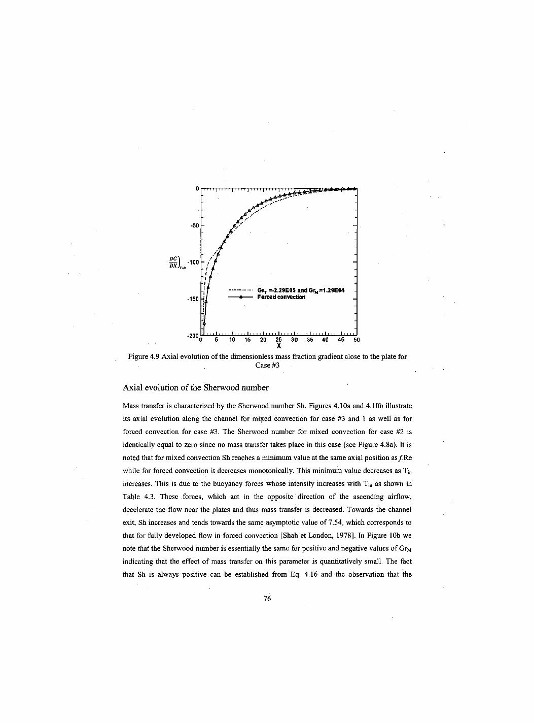
Figure 4.9 Axial evolution of the dimensionless mass fraction gradient close to the plate for Case #3
Axial evolution of the Sherwood number
Mass transfer is characterized by the Sherwood number Sh. Figures 4.10a and 4.10b illustrate
its axial evolution along the channel for mixed convection for case #3 and 1 as well as for
forced convection for case #3. The Sherwood number for mixed convection for case #2 is
identically equal to zero since no mass transfer takes place in this case (see Figure 4.8a). It is
noted that for mixed convection Sh reaches a minimum value at the same axial position as /Re
while for forced convection it decreases monotonically. This minimum value decreases as Tjn
increases. This is due to the buoyancy forces whose intensity increases with Tjn as shown in
Table 4.3. These forces, which act in the opposite direction of the ascending airflow,
decelerate the flow near the plates and thus mass transfer is decreased. Towards the channel
exit, Sh increases and tends towards the same asymptotic value of 7.54, which corresponds to
that for fully developed flow in forced convection [Shah et London, 1978]. In Figure 10b we
note that the Sherwood number is essentially the same for positive and negative values of GrM
indicating that the effect of mass transfer on this parameter is quantitatively small. The fact
that Sh is always positive can be established from Eq. 4.16 and the observation that the
76
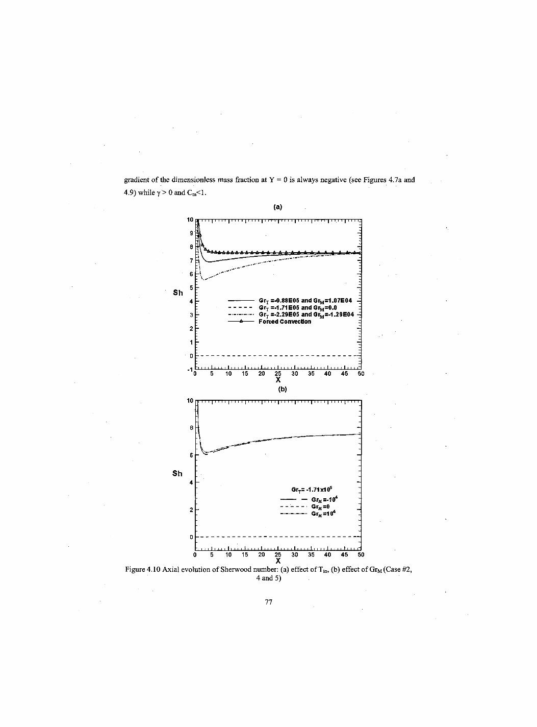
gradient of the dimensionless mass fraction at Y = 0 is always negative (see Figures 4.7a and
4.9) while y > 0 and Cm<l.
Sh
10
9
8
7
6
5
4
3
2
1
0
- 1
(a) I I I I I I I I I I I II I I I I I I I I I ! I I I I I I I I I I I I I II I I I I I I I I I L
A HftdaAAAAAAA AAAAAAAA —*—1 f *
GrT =-0.88E05 and GrM=1.07E04 Grr =-1.71E05 and GrM=0.0 GrT =-2.29E05 and GrM=-1.29E04
-A Forced Convection
11 i i i I 11 1 1 111 11 1 111 1 1 11' 11 1
0 5 10 15 20 25 30 35 40 45 50 X (b)
10 MI i i i 11 i i i 11 i i i | i i i i 11 i i i 11 i i i 11 i i i | i i i i | i i i i 11 i i i
J Sh
GrT=-1.71x10s
GrM=-104
GrM=0 GrM =10*
0 '11 ' ' ' 1 1 1 1 1 l11 11 11111 1 11 11 11 1 11 11 1 11 1 1 1 11 1
0 5 10 15 20 25 30 35 40 45 50 X
Figure 4.10 Axial evolution of Sherwood number: (a) effect of Tj„, (b) effect of GrM (Case #2, 4 and 5)
77
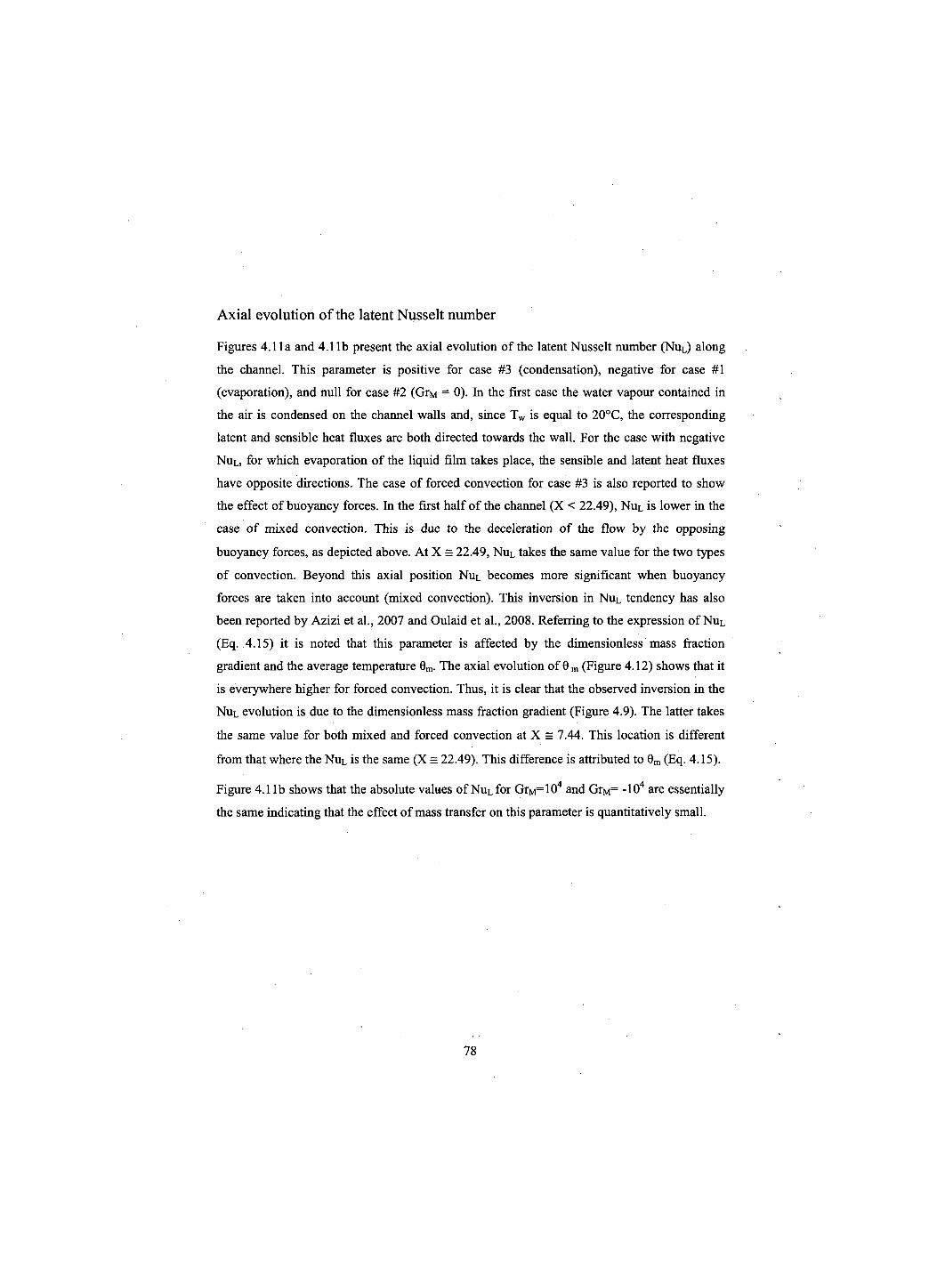
Axial evolution of the latent Nusselt number
Figures 4.11a and 4.11b present the axial evolution of the latent Nusselt number (NUL) along
the channel. This parameter is positive for case #3 (condensation), negative for case #1
(evaporation), and null for case #2 (GrM = 0). In the first case the water vapour contained in
the air is condensed on the channel walls and, since Tw is equal to 20°C, the corresponding
latent and sensible heat fluxes are both directed towards the wall. For the case with negative
NUL, for which evaporation of the liquid film takes place, the sensible and latent heat fluxes
have opposite directions. The case of forced convection for case #3 is also reported to show
the effect of buoyancy forces. In the first half of the channel (X < 22.49), NuL is lower in the
case of mixed convection. This is due to the deceleration of the flow by the opposing
buoyancy forces, as depicted above. At X = 22.49, NUL takes the same value for the two types
of convection. Beyond this axial position NUL becomes more significant when buoyancy
forces are taken into account (mixed convection). This inversion in NUL tendency has also
been reported by Azizi et al., 2007 and Oulaid et al., 2008. Referring to the expression of NUL
(Eq. 4.15) it is noted that this parameter is affected by the dimensionless mass fraction
gradient and the average temperature 0m. The axial evolution of 0 m (Figure 4.12) shows that it
is everywhere higher for forced convection. Thus, it is clear that the observed inversion in the
NUL evolution is due to the dimensionless mass fraction gradient (Figure 4.9). The latter takes
the same value for both mixed and forced convection at X = 7.44. This location is different
from that where the NUL is the same (X = 22.49). This difference is attributed to 0m (Eq. 4.15).
Figure 4.1 lb shows that the absolute values of NuL for GrM=104 and GrM= -104 are essentially
the same indicating that the effect of mass transfer on this parameter is quantitatively small.
78
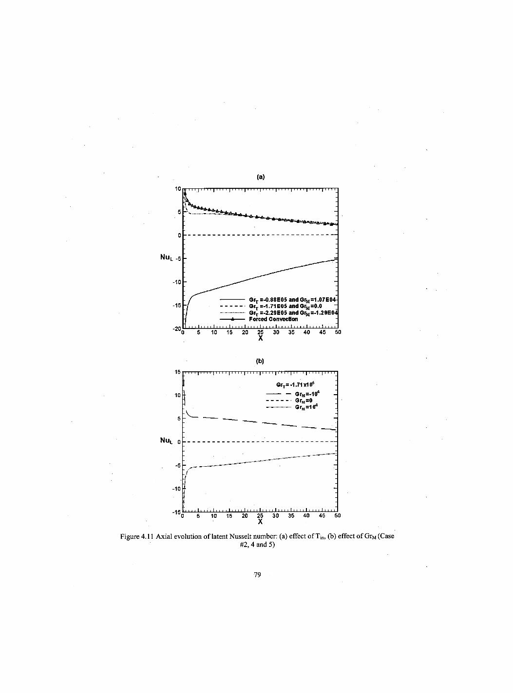
(a)
Nu L -5
-15 GrT =-0.88E05 and GrM=1.07E04-OrT =-1.71 E05 and GrM=0.0 GrT =-2.29E05 and GrM=-1.29E04j Forced Convection
mm ii 11 i 11 i 11 11 11 i 11 i 11 111 i 111 » 11 111 i 111 11111 i 11 111 i i 0 5 10 15 20 25 30 35 40 45 50
(b)
1 5 II I I I I 11 I I I 11 I I I 11 I I I 11 I I I 11 I I I 11 I I I 11 I I I 11 I I I 11 I I
GrT= -1.71 xlO5
10 l i Gr„=-104
5 -
•M GrM=0 Gr^lO4
N U L 0
- 1 0
He i i i i I i i I i I i i i i I i i i i Ii i i i I i i i i Ii i i i I i i i i I i i i i I i i i i 0 5 10 15 20 25 30 35 40 45 50
Figure 4.11 Axial evolution of latent Nusselt number: (a) effect of Tin, (b) effect of GrM (Case #2, 4 and 5)
79
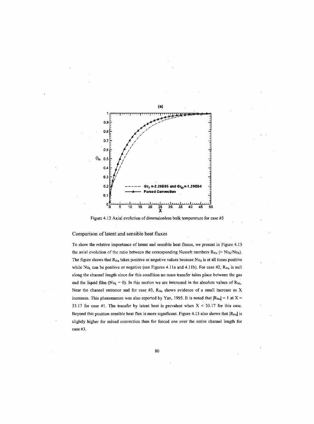
(a)
Comparison of latent and sensible heat fluxes
To show the relative importance of latent and sensible heat fluxes, we present in Figure 4.13
the axial evolution of the ratio between the corresponding Nusselt numbers RNu (= Nui/Nus).
The figure shows that RNu takes positive or negative values because Nus is at all times positive
while NUl can be positive or negative (see Figures 4.1 la and 4.1 lb). For case #2, RNu is null
along the channel length since for this condition no mass transfer takes place between the gas
and the liquid film (NuL = 0). In this section we are interested in the absolute values of RNu.
Near the channel entrance and for case #3, RNu shows evidence of a small increase as X
increases. This phenomenon was also reported by Yan, 1995. It is noted that |RNu| = 1 at X =
33.17 for case #1. The transfer by latent heat is prevalent when X < 33.17 for this case.
Beyond this position sensible heat flux is more significant. Figure 4.13 also shows that |RNu| is
slightly higher for mixed convection than for forced one over the entire channel length for
case #3.
80

Figure 4.13 Axial evolution of the latent to the sensible Nusselt numbers ratio
4.5 Flow reversal chart
In order to establish the conditions for the existence of flow reversal, a sequence of
simulations were carried out. Thus, for a given Re we varied Tjn (i.e. Grx) and at the same time
we varied <j>;n to maintain GrM fixed until detecting a negative axial velocity. Three values of
GrM were considered (GrM = -104, 0, 104). All these combinations of temperature and mass
fraction satisfy the condition for the application of the Boussinesq approximation (the density
variation does not exceed 10%). These series of numerical experiments enabled us to draw the
flow reversal charts for different aspect ratios of the channel (y = 1/35, 1/50 and 1/65). These
flow reversal charts are represented in Figures 4.14a, 4.14b and 4.14c. It is noted that for a
given GrM an increase of Re increases the absolute value of the critical GrT which induces
flow reversal. Indeed, as Re increases the magnitude of the opposing thermal buoyancy force
that induces flow reversal increases too.
The dependence of this critical thermal Grashof number on the Reynolds number is essentially
linear and can be expresses by the following correlations:
81
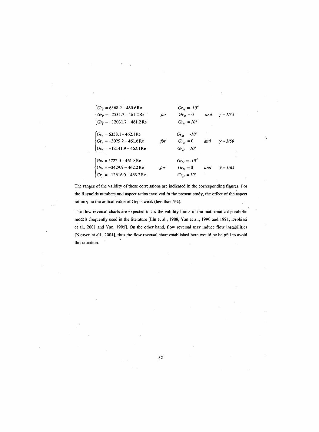
GrT =6368.9 -460.6 Re GrT =-2531.7-461.2 Re Grr = -12031.7-461.2 Re
for GrM=-104
GrM = 0
GrM=104
and y = 1/35
GrT =6358.1-462.1 Re GrT =-3029.2 -461.6 Re GrT =-12141.9-462,1 Re
for GrM = -10 GrM= 0 GrM=10<
and y =
GrT = 5722.0-461.8Re GrT = -3429.9 - 462.2 Re GrT =-12616.0-463.2 Re
for GrM = -104
GrM= 0 GrM=104
and Y =
The ranges of the validity of these correlations are indicated in the corresponding figures. For
the Reynolds numbers and aspect ratios involved in the present study, the effect of the aspect
ration y on the critical value of Grx is weak (less than 5%).
The flow reversal charts are expected to fix the validity limits of the mathematical parabolic
models frequently used in the literature [Lin et al., 1988, Yan et al., 1990 and 1991, Debbissi
et al., 2001 and Yan, 1995], On the other hand, flow reversal may induce flow instabilities
[Nguyen et all., 2004], thus the flow reversal chart established here would be helpful to avoid
this situation.
82
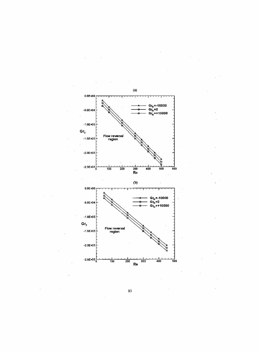
(a)
Re
(b) O.OE-tOO —i—i—i—i—|—i—i—i—i—|—i—i—i—i—|—i—i—i—i—|—i—i—i—r
-5.0E+04
-1.0E-KJ5
irT
-1.5E-KJ5
-2.0E-K)5
Flow reversal region
— GrM=-10000 GrM=0
e GrM=+10000
-2.5E-HJ5, 100 I i i i I I I I I l_
200 300 Re
400 500
83
(C)
O.OE-tOO
-5.0E404
GrT
-1.0E+05
-1.5E-H)50 1 0 Q 2 0 Q 3 0 Q
Re
Figure 4.14 Flow reversal chart: (a) y = 1/35, (b) y = 1/50 and (c) y = 1/65
4.6 Conclusion
The effects of buoyancy forces on combined convection mixed heat and mass transfer with
phase change have been investigated numerically for an upward flow of warm humid air in a
vertical parallel-plate channel with cool walls. The influence of the gas temperature at the
channel entrance and the mass diffusion Grashof number were studied. Results show that the i buoyancy forces, mostly of thermal origin, decelerate the flow near the walls and induce flow
reversal for high temperature differences between the gas and the walls. Thus they reduce heat
and mass transfer. Furthermore, the conditions for the existence of flow reversal have been
determined for different aspect ratios and mass diffusion Grashof numbers. They are presented
in charts and by analytical correlations specifying the critical thermal Grashof number as a
function of the Reynolds number.
84
CHAPITRE 5 Simultaneous heat and mass transfer in inclined channel with asymmetrical conditions
Auteurs et affiliation: O. OULAID: etudiant au doctorat, Universite de Sherbrooke, Faeulte de genie, Departement de genie mecanique en cotutelle avec l'Universite Cadi Ayyad, Faeulte des sciences-Semlalia, Departement de physique, Marrakech 40 001, Maroc.
B. BENHAMOU: professeur, Universite Cadi Ayyad, Faeulte des sciences-Semlalia, Departement de physique, Marrakech 40 001, Maroc.
N. GALANIS: professeur, Universite de Sherbrooke, Faeulte de genie, Departement de genie mecanique.
Date de soumission : Mars 2010
Etat de 1'acceptation : en evaluation
Revue: Journal of Applied Fluid Mechanics
Reference: (Oulaid et coll. 20IX)
Titre fran9ais: Transferts simultanes de chaleur et de masse dans canal incline avec des conditions asymetriques.
85
Resume
Le travail presente ici est une etude numeriquement sur le transfert simultane de chaleur et de
masse avec changement de phase dans un canal incline. Ce canal est forme par deux plaques
planes paralleles dont celle inferieure est couverte par un film d'eau alors que celle superieure
est consideree impermeable. On impose aux deux plaques une temperature constante
superieure a celle de l'air humide a l'entree du canal. Les resultats numeriques de cette etude
montrent que les forces d'Archimede diminuent le transfert de chaleur et de masse et causent
le renversement de l'ecoulement. Ces resultats dependent essentiellement de d'inclinaison du
canal. Ainsi, les conditions d'existence du renversement sont presentees par des abaques ainsi
que des expressions analytiques. Ces abaques et expressions donnent le nombre de Grashof
d'origine thermique critique en fonction du nombre de Reynolds pour differentes valeurs du
nombre de Grashof d'origine massique, differents rapports de forme et angle d'inclinaison.
Mots cles: Transfert de chaleur et de masse, Convection mixte, Changement de phase, Canal
incline, Carte de renversement.
86
Abstract
The present work is a numerical study of simultaneous heat and mass transfer with phase
change in an inclined channel formed by two parallel plates. The lower one is covered by a
thin liquid water film and the upper one is considered impermeable. The plates are maintained
at a constant temperature. The liquid film is assumed to be extremely thin and its temperature
is uniform and equal to that of the wall. Thermo-physical properties are considered constant
and the Boussinesq assumption is adopted. Results show that buoyancy forces have an
important effect on the hydrodynamic, thermal and mass fraction fields. These effects depend
on the channel inclination and may result on flow reversal when the channel approaches the
vertical position. This phenomenon is addressed and a flow reversal chart, as well as the
corresponding analytical correlations, for different channel inclinations is given. These
correlations give the values of Grashof numbers, which induce flow reversal for a given
Reynolds number and inclination angle.
Keywords: Mixed convection, Phase change, Flow reversal chart.
87
5.1 Introduction
The phenomena of coupled heat and mass transfer have been extensively studied in the
literature and the majority of the published works focus on horizontal and vertical
configurations. Among the recent studies Laaroussi et al., 2009 conducted a numerical study
of laminar mixed convection in a vertical parallel-plate channel with evaporation of thin liquid
films wetting the walls. The plates were maintained at a constant temperature and the liquid
film thickness was assumed to be negligible. The airflow was downwards and the film was
either liquid water or hexane. The authors compared the results obtained with constant
properties (Boussinesq model) with those calculated by considering variable density.
Ait Hammou et al., 2004 have examined numerically the effects of simultaneous heat and
mass transfer on downward laminar flow of humid air in an isothermal vertical channel with
wetted walls. They affirmed that, depending on the inlet conditions of the humid air, mass
transfer may result in evaporation or condensation. On the other hand, it was demonstrated
that thermal and solutal buoyancy forces have significant effects on flow characteristics. In all
cases analyzed in this study, the authors have not detected flow reversal. Combined buoyancy
effects of thermal and mass diffusion on laminar mixed convection in a vertical isothermal
channel were also studied by Oulaid et al., 2010a. The results show that buoyancy forces
decelerate the flow near the channel walls and cause flow reversal.
Heat and mass transfer mixed convection in inclined geometries has not been extensively
studied as in vertical and horizontal configurations. Among the few studies addressing
inclined configurations we mention that of Said et al., 2005, who investigated numerically
turbulent natural heat convection between inclined isothermal plates. Their results show that
the average Nusselt number is reduced as the inclination angle increases and that the overall
average Nusselt number at different inclination angles can be presented by a single correlation.
The problem of heat and mass transfer mixed convection heat transfer enhancement through
film evaporation in inclined square ducts was studied numerically by Jang et al., 2005. Their
results show that the friction factor as well as heat and mass transfer are affected considerably
by the inclination angle and the heat transfer rate can be enhanced to be 10 times of that
without mass transfer, especially for a system with a lower temperature.
88
Rheault and Bilgen, 1993 studied numerically steady laminar mixed heat convection in
vertical and inclined parallel-plate channels with asymmetric isothermal boundary conditions.
The authors show that the solution of the problem with flow reversal can be achieved in the
range of Peclet numbers from 10 to 150, where the effect of axial diffusion becomes critical.
Thus their results show that, the flow reversal near the colder wall and/or the center of the
channel becomes more pronounced when the Richardson number Gr/Re2 increases.
A two-phase modeling of laminar film condensation from vapor-gas mixtures in inclined
parallel-plate channels was presented by Siow et al., 2007. The upper plate is insulated and
impermeable while the bottom one is wetted by a liquid film and maintained isothermal. The
model uses a finite-control-volume method to solve the complete two-phase boundary-layer
equations. The authors' results show that, increasing the angle of inclination (i.e. decreasing
the Froude number) produces thinner, faster moving films. Increasing Reynolds number
always produced thinner films and higher Nusselt number. An exact analytical solution for the
liquid and mixture axial velocity profiles under end of condensation conditions is also
presented and compared with the numerical results.
In a previous work [Oulaid et al., 2010b] we investigated flow reversal in combined heat and
mass transfer laminar mixed convection with phase change in a vertical channel. The
conditions for the existence of flow reversal are presented in charts and analytical expressions
specifying the critical thermal Grashof number as a function of the Reynolds number for
different values of the solutal Grashof number and different aspect ratios of the channel.
The principal aim of the present investigation is to study the influence of the channel
inclination on the hydrodynamic, thermal and mass fraction fields, as well as to present criteria
for the occurrence of the phenomenon of flow reversal.
5.2 Description and Modeling of the problem
We consider a channel formed by two inclined parallel-plate channel and spaced in 2W
(Figure 5.1). These plates are wetted by a very thin water film and subject to a uniform
temperature Tw. The air enters with a uniform velocity profile Ui„, a temperature Tj„ and a
relative humidity <j)jn. The upward airflow is considered laminar and steady. We consider that
radiation, the heat transfer by inter-diffusion of species, viscous dissipation and the work of
89
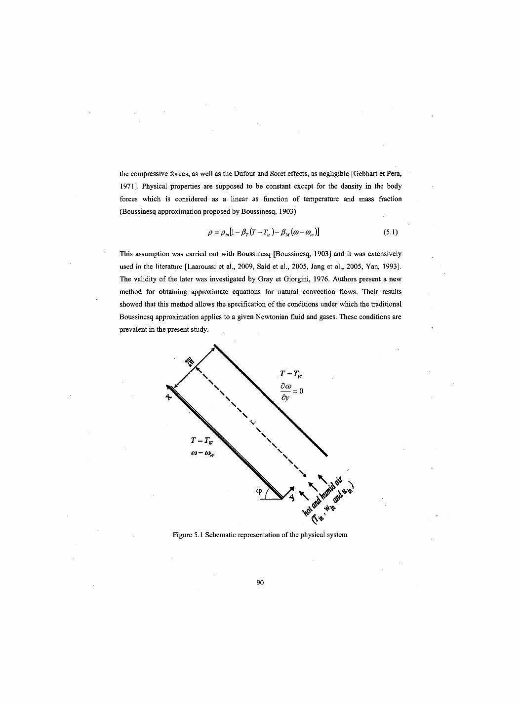
the compressive forces, as well as the Dufour and Soret effects, as negligible [Gebhart et Pera,
1971]. Physical properties are supposed to be constant except for the density in the body
forces which is considered as a linear as function of temperature and mass fraction
(Boussinesq approximation proposed by Boussinesq, 1903)
This assumption was carried out with Boussinesq [Boussinesq, 1903] and it was extensively
used in the literature [Laaroussi et al., 2009, Said et al., 2005, Jang et al., 2005, Yan, 1993].
The validity of the later was investigated by Gray et Giorgini, 1976. Authors present a new
method for obtaining approximate equations for natural convection flows. Their results
showed that this method allows the specification of the conditions under which the traditional
Boussinesq approximation applies to a given Newtonian fluid and gases. These conditions are
prevalent in the present study.
P = P,k-Pr{T-Tm)-PM{o}-CDm)] in (5.1)
Figure 5.1 Schematic representation of the physical system
90
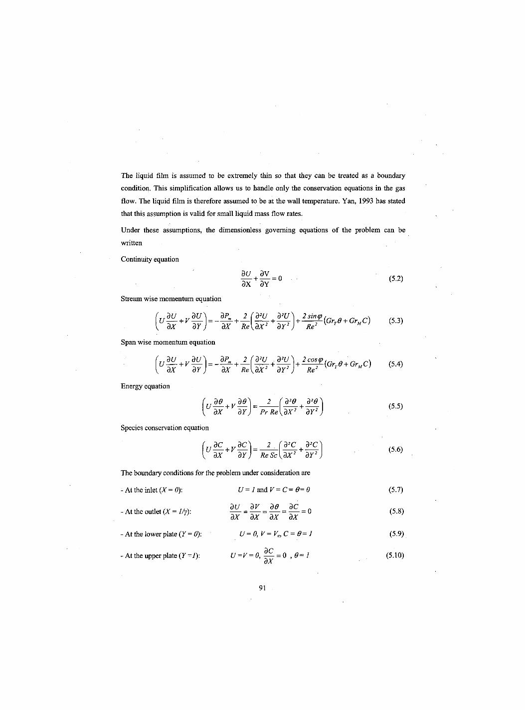
The liquid film is assumed to be extremely thin so that they can be treated as a boundary
condition. This simplification allows us to handle only the conservation equations in the gas
flow. The liquid film is therefore assumed to be at the wall temperature. Yan, 1993 has stated
that this assumption is valid for small liquid mass flow rates.
Under these assumptions, the dimensionless governing equations of the problem can be
written
Continuity equation
Stream wise momentum equation
QU dV n — + — = 0 dX dY
dX dY
Span wise momentum equation
dP„ dX Re
d2U d2U dX2+dY2 +
2-ff{GrTe + GrMC) Re
'uZL+yH dx dY dx Re{dX2 dY2) D"2 K T M '
Energy equation
v dX dY J
Re'
2 (d2e | d2d
Species conservation equation
'u^+rZ." v dX dY j
PrReKdX2 dY2
d2C d2C ReSc dX2+'dY2
The boundaiy conditions for the problem under consideration are
- At the inlet (X = 0):
- At the outlet (X = 1/y):
- At the lower plate (Y = 0):
- At the upper plate (Y=l):
U = 1 and V=C= 0=0
dU = dV = de = dC
dX ~ dX~ dX~ dX~
U=0, V= Ve,C = 0=l r)C
U = v=0, — = 0 , 0=1 dx
(5.2)
(5.3)
(5.4)
(5.5)
(5.6)
(5.7)
(5.8)
(5.9)
(5.10)
91
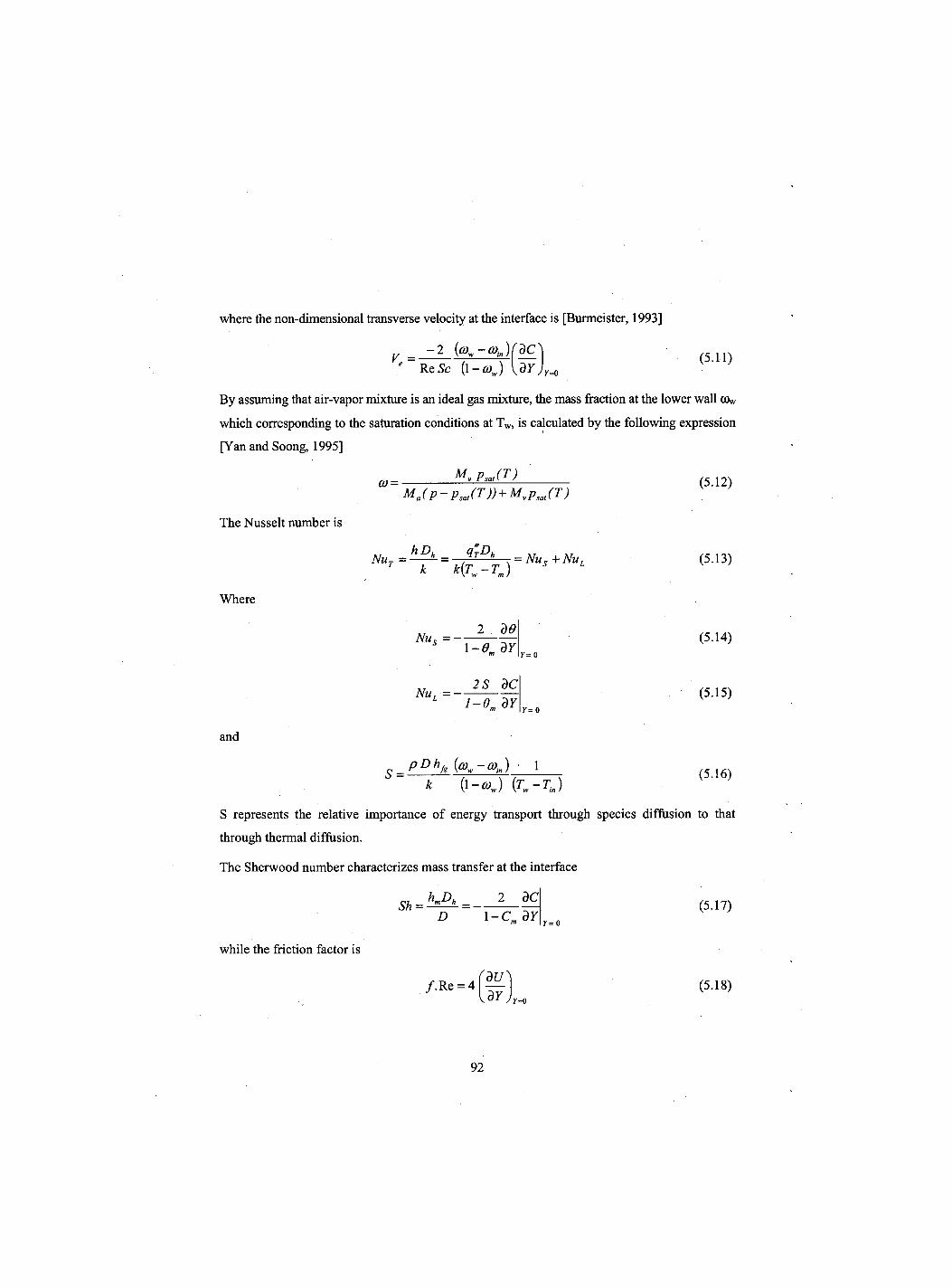
where the non-dimensional transverse velocity at the interface is [Burmeister, 1993]
y = -2 fa-aJfdC (5.11) Re Sc {l-eoj
By assuming that air-vapor mixture is an ideal gas mixture, the mass fraction at the lower wall GV
which corresponding to the saturation conditions at Tw, is calculated by the following expression
[Yan and Soong, 1995]
Mv PsJT) (0 =
The Nusselt number is
Where
Ma(p-psJT)) + MvPsJT)
Nur=^- = /tD" , = Nu5+NUl k k{Tw-Tm)
2 de
(5.12)
(5.13)
Nu. = 1 - 0 . 3 Y
2S dC
and
S =
Nu, = — l-em dY
pDhfg{o)w-coin) 1
(5.14)
(5.15)
(5.16) k (1 -cow) (Tw —Tin)
S represents the relative importance of energy transport through species diffusion to that
through thermal diffusion.
The Sherwood number characterizes mass transfer at the interface
h„D„ 2 dC Sh =
D 1 -CdY (5.17)
Y= 0
while the friction factor is
/ . R e = 4 'dU} dY
(5.18) JY=o
92
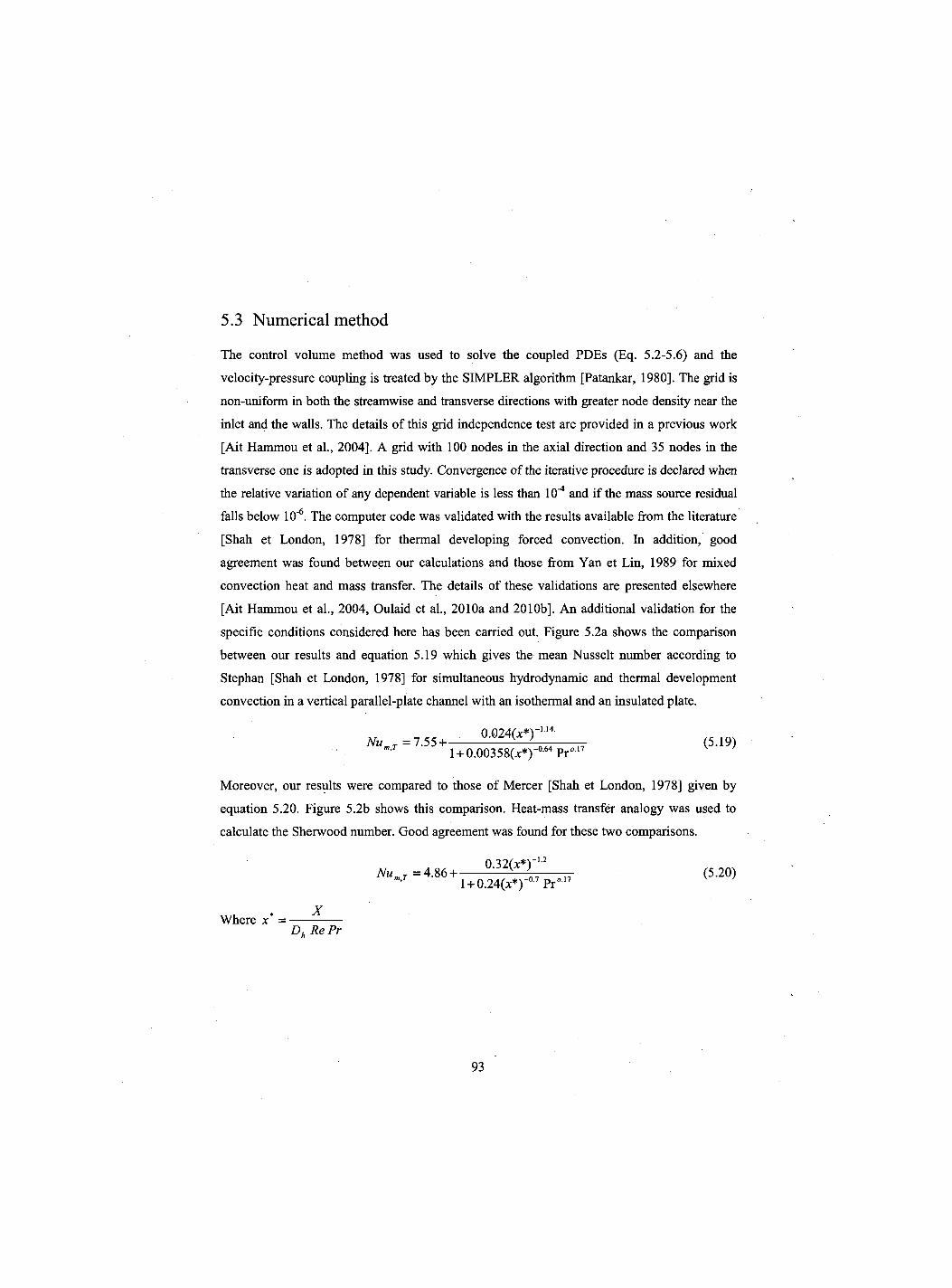
5.3 Numerical method
The control volume method was used to solve the coupled PDEs (Eq. 5.2-5.6) and the
velocity-pressure coupling is treated by the SIMPLER algorithm [Patankar, 1980]. The grid is
non-uniform in both the streamwise and transverse directions with greater node density near the
inlet and the walls. The details of this grid independence test are provided in a previous work
[Ait Hammou et al., 2004]. A grid with 100 nodes in the axial direction and 35 nodes in the
transverse one is adopted in this study. Convergence of the iterative procedure is declared when
the relative variation of any dependent variable is less than 10"* and if the mass source residual
falls below 10'6. The computer code was validated with the results available from the literature
[Shah et London, 1978] for thermal developing forced convection. In addition, good
agreement was found between our calculations and those from Yan et Lin, 1989 for mixed
convection heat and mass transfer. The details of these validations are presented elsewhere
[Ait Hammou et al., 2004, Oulaid et al., 2010a and 2010b]. An additional validation for the
specific conditions considered here has been carried out. Figure 5.2a shows the comparison
between our results and equation 5.19 which gives the mean Nusselt number according to
Stephan [Shah et London, 1978] for simultaneous hydrodynamic and thermal development
convection in a vertical parallel-plate channel with an isothermal and an insulated plate.
0.024(;c*)' l + 0.00358(jt*)-°'64Pro1 N u m J = 1 . 5 5 + : (5.19)
Moreover, our results were compared to those of Mercer [Shah et London, 1978] given by
equation 5.20. Figure 5.2b shows this comparison. Heat-mass transfer analogy was used to
calculate the Sherwood number. Good agreement was found for these two comparisons.
NumT =4.86 + Q"32(X"')n712 n (5-2°)
' l + 0.24(x*)-° Pr
X Where x* =-
Dh Re Pr
93
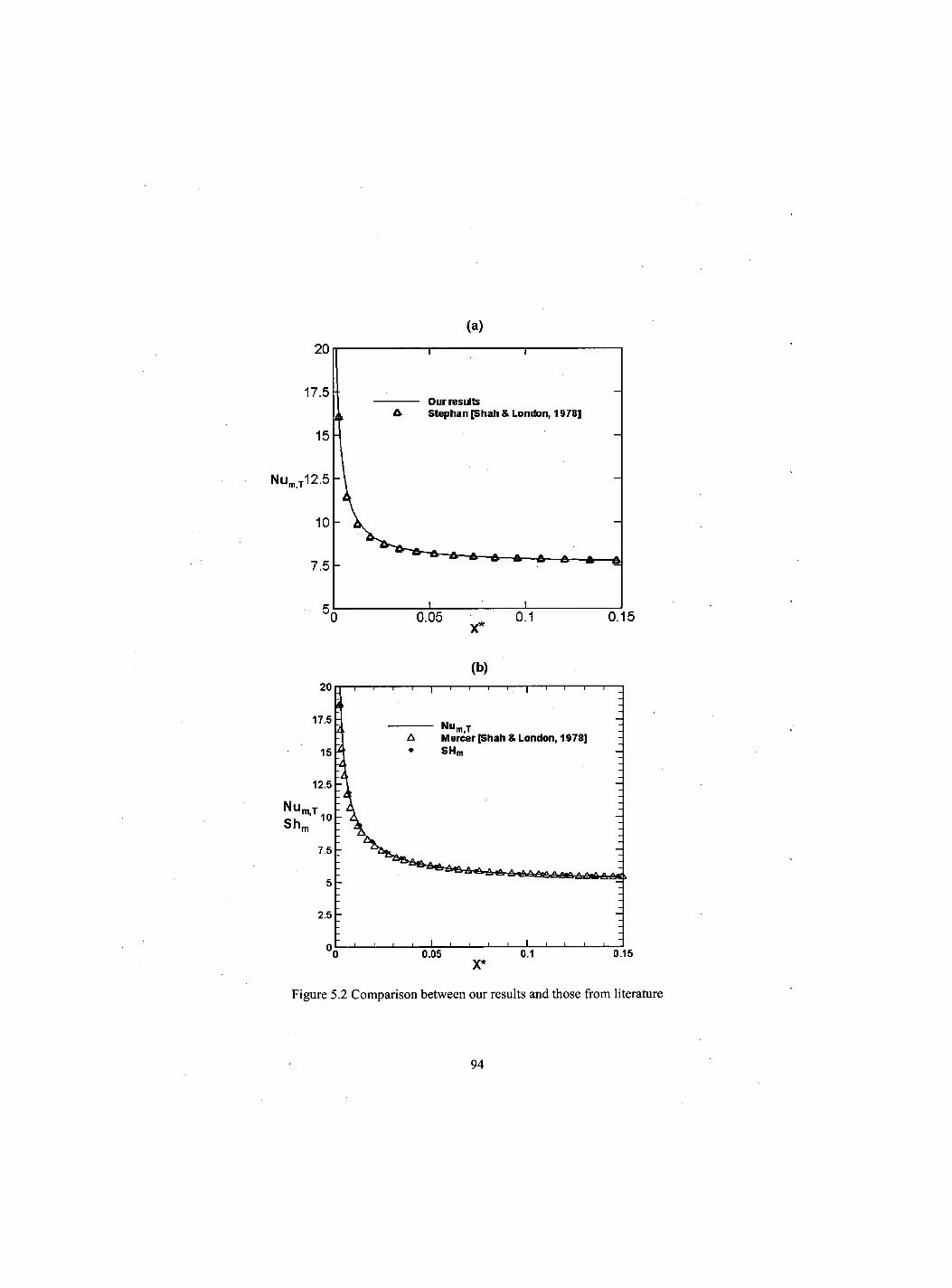
(a)
(b)
Figure 5.2 Comparison between our results and those from literature
94
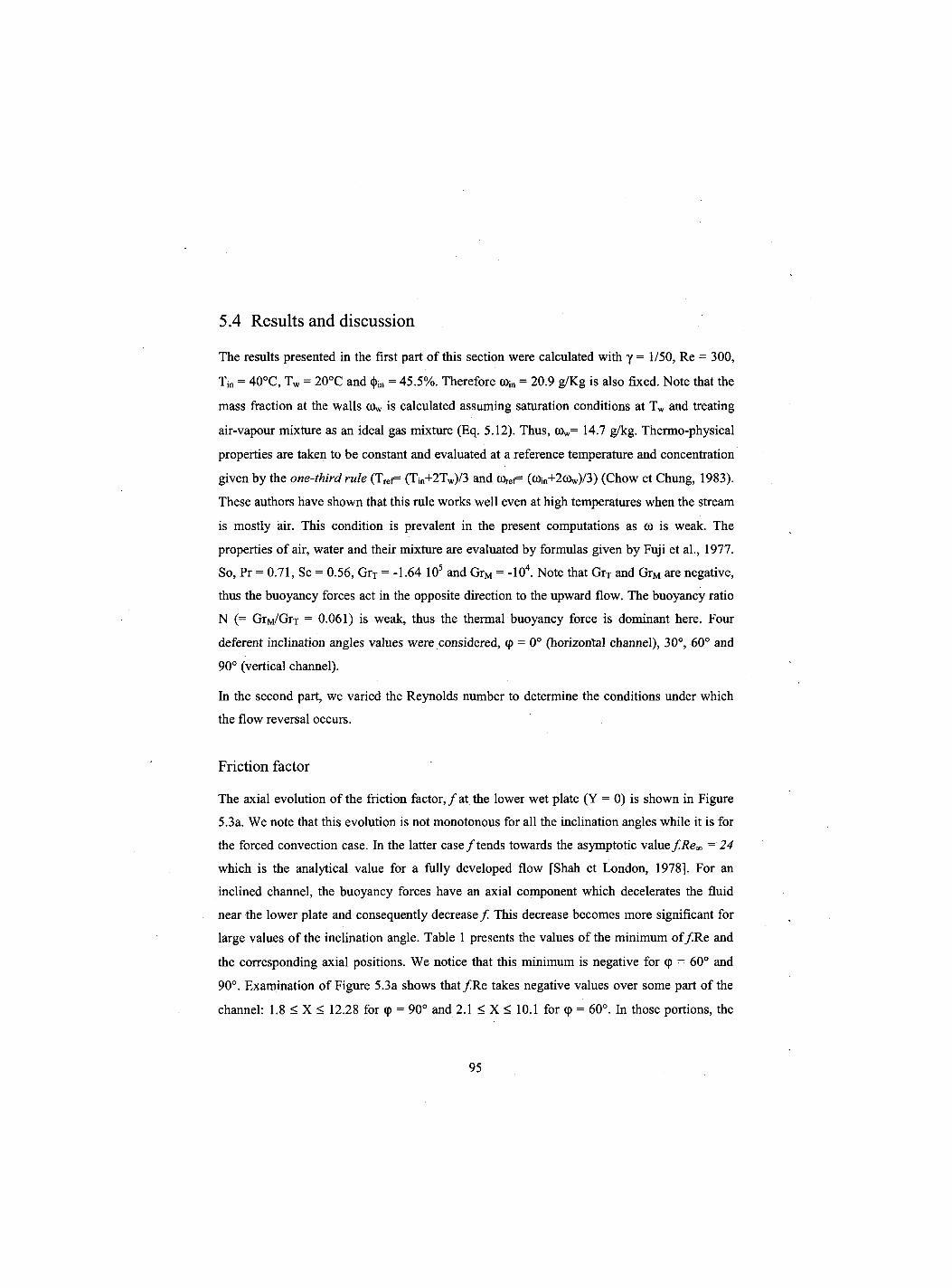
5.4 Results and discussion
The results presented in the first part of this section were calculated with y = 1/50, Re = 300,
Tin = 40°C, Tw = 20°C and <J>in = 45.5%. Therefore C0in = 20.9 g/Kg is also fixed. Note that the
mass fraction at the walls C0w is calculated assuming saturation conditions at Tw and treating
air-vapour mixture as an ideal gas mixture (Eq. 5.12). Thus, C0w= 14.7 g/kg. Thermo-physical
properties are taken to be constant and evaluated at a reference temperature and concentration
given by the one-third rule (Tref= (Tjn+2Tw)/3 and 0)ref= (a>in+2c0w)/3) (Chow et Chung, 1983).
These authors have shown that this rule works well even at high temperatures when the stream
is mostly air. This condition is prevalent in the present computations as (0 is weak. The
properties of air, water and their mixture are evaluated by formulas given by Fuji et al., 1977.
So, Pr = 0.71, Sc = 0.56, GrT = -1.64 105 and GrM = -104. Note that GrT and GrM are negative,
thus the buoyancy forces act in the opposite direction to the upward flow. The buoyancy ratio
N (= GrM/Grr = 0.061) is weak, thus the thermal buoyancy force is dominant here. Four
deferent inclination angles values were considered, (p = 0° (horizontal channel), 30°, 60° and
90° (vertical channel).
In the second part, we varied the Reynolds number to determine the conditions under which
the flow reversal occurs.
Friction factor
The axial evolution of the friction factor,/at the lower wet plate (Y = 0) is shown in Figure
5.3a. We note that this evolution is not monotonous for all the inclination angles while it is for
the forced convection case. In the latter case / tends towards the asymptotic value f.Re«, = 24
which is the analytical value for a fully developed flow [Shah et London, 1978]. For an
inclined channel, the buoyancy forces have an axial component which decelerates the fluid
near the lower plate and consequently decrease / This decrease becomes more significant for
large values of the inclination angle. Table 1 presents the values of the minimum o f / R e and
the corresponding axial positions. We notice that this minimum is negative for 9 = 60° and
90°. Examination of Figure 5.3a shows that / R e takes negative values over some part of the
channel: 1.8 < X < 12.28 for 9 = 90° and 2.1 < X < 10.1 for <p = 60°. In those portions, the
95
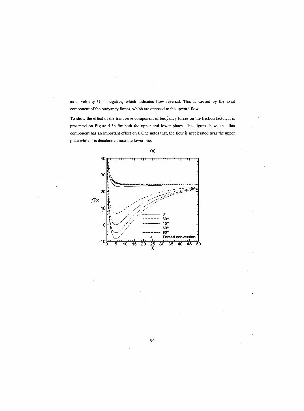
axial velocity U is negative, which indicates flow reversal. This is caused by the axial
component of the buoyancy forces, which are opposed to the upward flow.
To show the effect of the transverse component of buoyancy forces on the friction factor, it is
presented on Figure 5.3b for both the upper and lower plates. This figure shows that this
component has an important effect o n / One notes that, the flow is accelerated near the upper
plate while it is decelerated near the lower one.
(a)
96
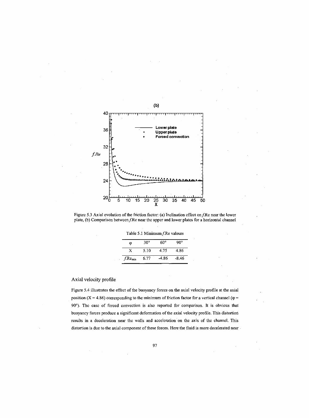
(b)
X
Figure 5.3 Axial evolution of the friction factor: (a) Inclination effect on /Re near the lower plate, (b) Comparison between/Re near the upper and lower plates for a horizontal channel
Table 5.1 Minimum/Re valeurs
<P 30° 60° 90°
X 5.10 4.75 4.86
/ R F I M I N 6.77 -4.86 -8.46
Axial velocity profile
Figure 5.4 illustrates the effect of the buoyancy forces on the axial velocity profile at the axial
position (X = 4.86) corresponding to the minimum of friction factor for a vertical channel (<p =
90°). The case of forced convection is also reported for comparison. It is obvious that
buoyancy forces produce a significant deformation of the axial velocity profile. This distortion
results in a deceleration near the walls and acceleration on the axis of the channel. This
distortion is due to the axial component of these forces. Here the fluid is more decelerated near
97
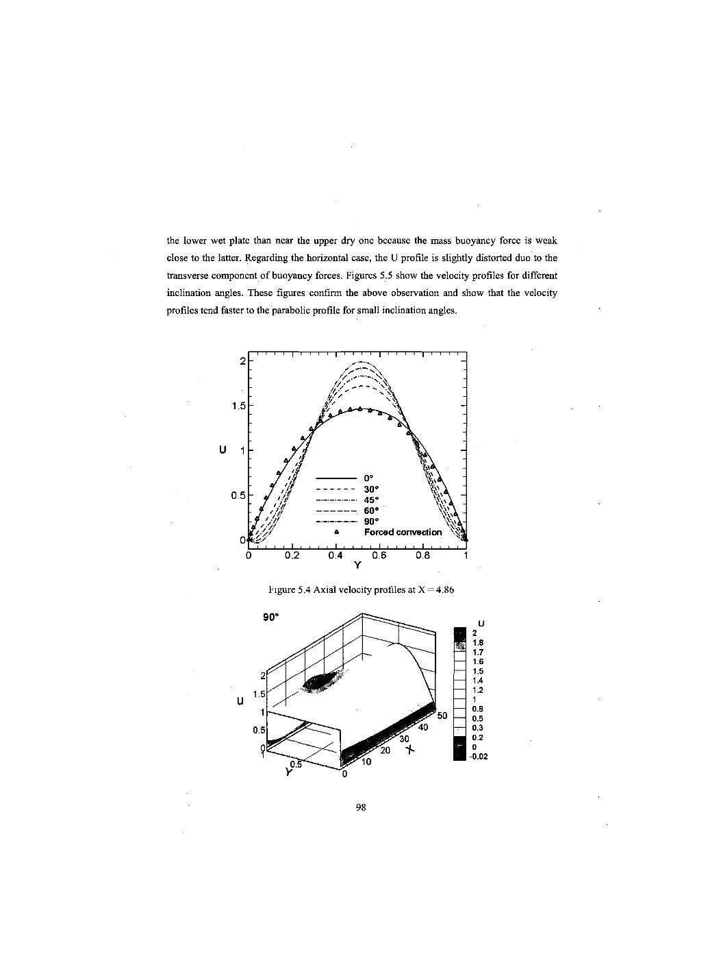
the lower wet plate than near the upper dry one because the mass buoyancy force is weak
close to the latter. Regarding the horizontal case, the U profile is slightly distorted duo to the
transverse component of buoyancy forces. Figures 5.5 show the velocity profiles for different
inclination angles. These figures confirm the above observation and show that the velocity
profiles tend faster to the parabolic profile for small inclination angles.
Y
Figure 5.4 Axial velocity profiles at X 4.86
98
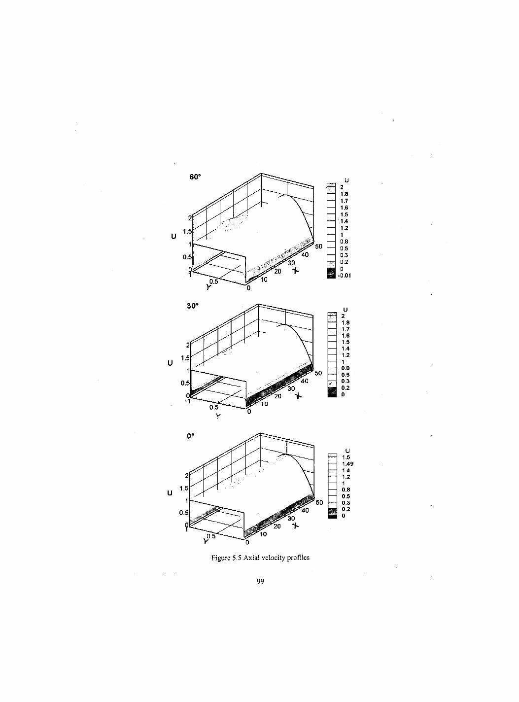
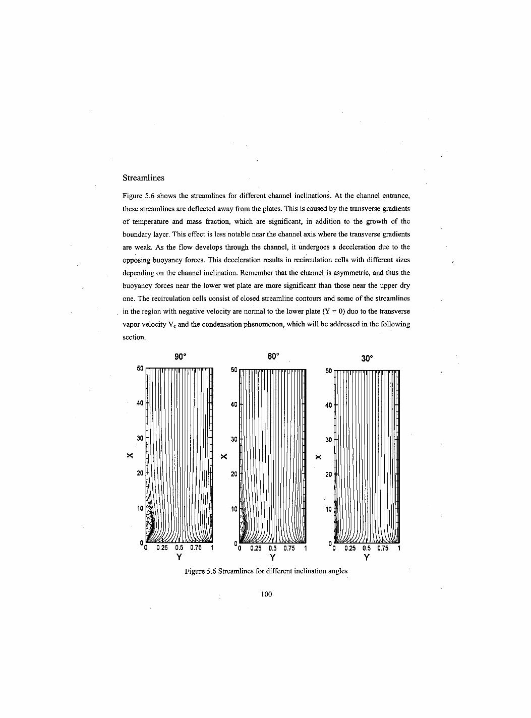
Streamlines
Figure 5.6 shows the streamlines for different channel inclinations. At the channel entrance,
these streamlines are deflected away from the plates. This is caused by the transverse gradients
of temperature and mass fraction, which are significant, in addition to the growth of the
boundary layer. This effect is less notable near the channel axis where the transverse gradients
are weak. As the flow develops through the channel, it undergoes a deceleration due to the
opposing buoyancy forces. This deceleration results in recirculation cells with different sizes
depending on the channel inclination. Remember that the channel is asymmetric, and thus the
buoyancy forces near the lower wet plate are more significant than those near the upper dry
one. The recirculation cells consist of closed streamline contours and some of the streamlines
in the region with negative velocity are normal to the lower plate (Y = 0) duo to the transverse
vapor velocity Ve and the condensation phenomenon, which will be addressed in the following
section.
90° 60° 30°
Figure 5.6 Streamlines for different inclination angles
100
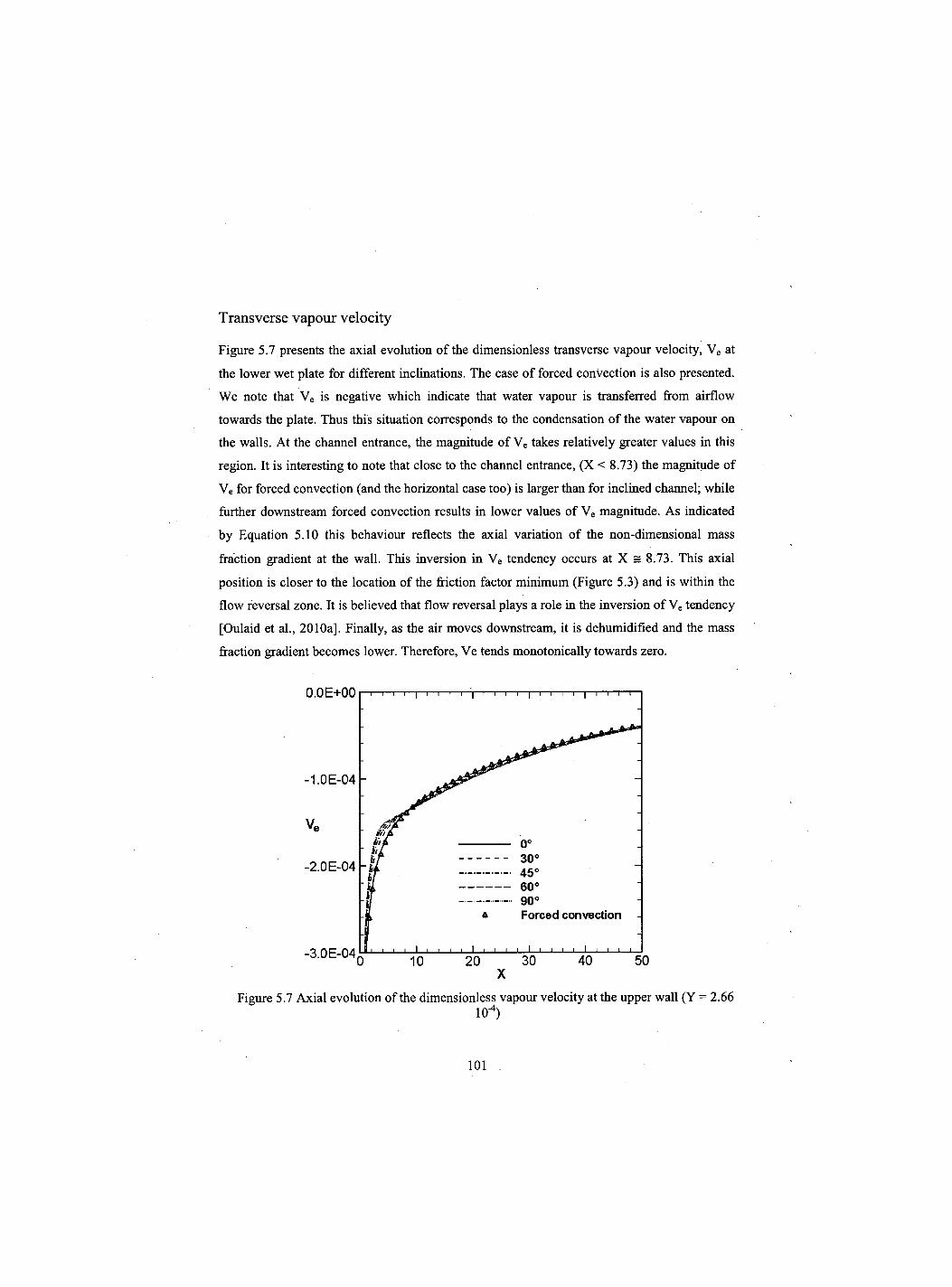
Transverse vapour velocity
Figure 5.7 presents the axial evolution of the dimensionless transverse vapour velocity, Ve at
the lower wet plate for different inclinations. The case of forced convection is also presented.
We note that Ve is negative which indicate that water vapour is transferred from airflow
towards the plate. Thus this situation corresponds to the condensation of the water vapour on
the walls. At the channel entrance, the magnitude of Ve takes relatively greater values in this
region. It is interesting to note that close to the channel entrance, (X < 8.73) the magnitude of
Ve for forced convection (and the horizontal case too) is larger than for inclined channel; while
further downstream forced convection results in lower values of Ve magnitude. As indicated
by Equation 5.10 this behaviour reflects the axial variation of the non-dimensional mass
fraction gradient at the wall. This inversion in Ve tendency occurs at X = 8.73. This axial
position is closer to the location of the friction factor minimum (Figure 5.3) and is within the
flow reversal zone. It is believed that flow reversal plays a role in the inversion of Ve tendency
[Oulaid et al., 2010a], Finally, as the air moves downstream, it is dehumidified and the mass
fraction gradient becomes lower. Therefore, Ve tends monotonically towards zero.
Figure 5.7 Axial evolution of the dimensionless vapour velocity at the upper wall (Y = 2.66 10"4)
101
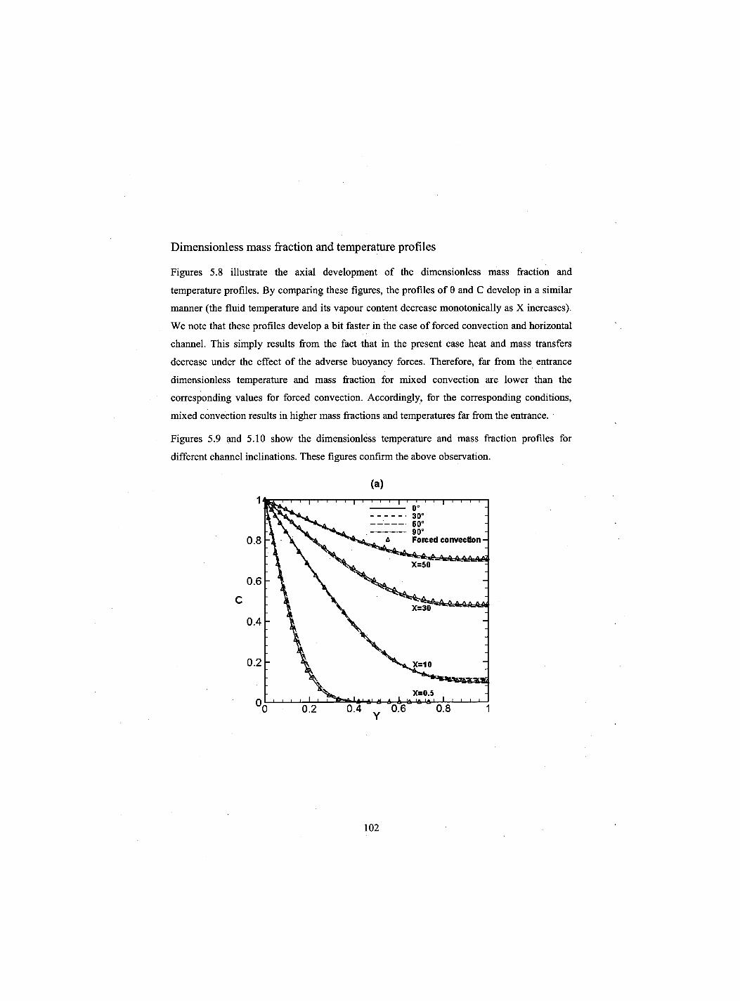
Dimensionless mass fraction and temperature profiles
Figures 5.8 illustrate the axial development of the dimensionless mass fraction and
temperature profiles. By comparing these figures, the profiles of 0 and C develop in a similar
manner (the fluid temperature and its vapour content decrease monotonically as X increases).
We note that these profiles develop a bit faster in the case of forced convection and horizontal
channel. This simply results from the fact that in the present case heat and mass transfers
decrease under the effect of the adverse buoyancy forces. Therefore, far from the entrance
dimensionless temperature and mass fraction for mixed convection are lower than the
corresponding values for forced convection. Accordingly, for the corresponding conditions,
mixed convection results in higher mass fractions and temperatures far from the entrance.
Figures 5.9 and 5.10 show the dimensionless temperature and mass fraction profiles for
different channel inclinations. These figures confirm the above observation.
(a) 1
0.8
0.6
C
0.4
0.2
0,
102
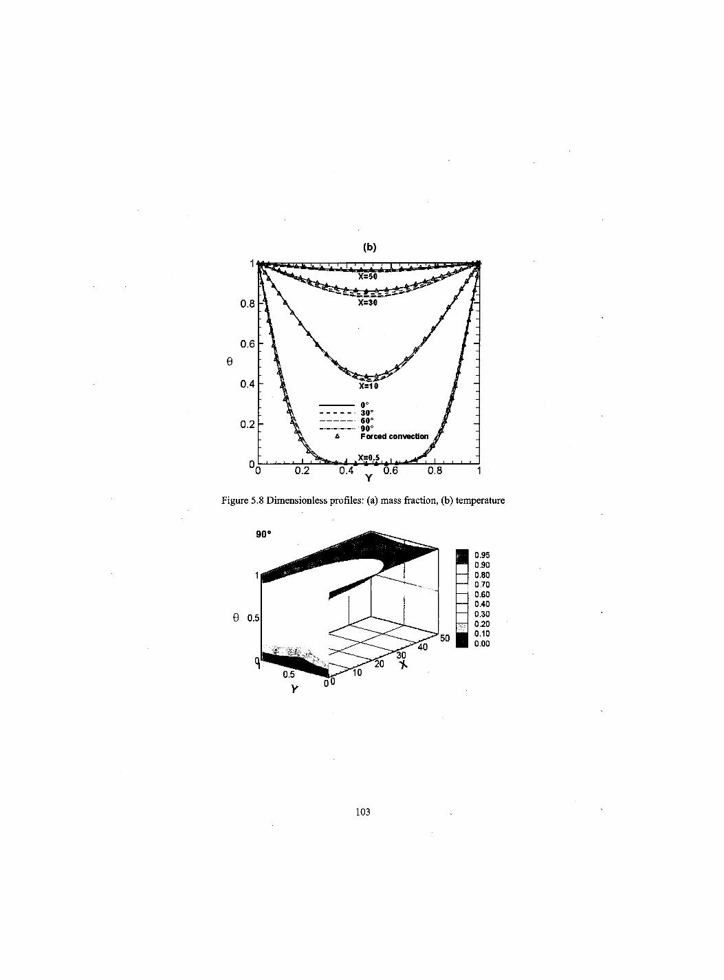
103
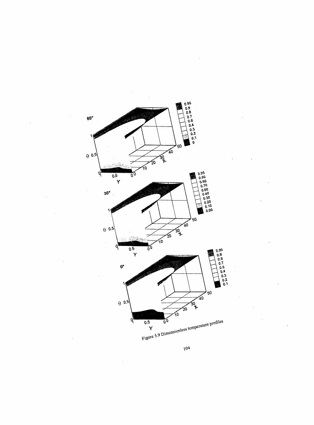
figute 5.9 D ^ .tvless
ifiVes
\04
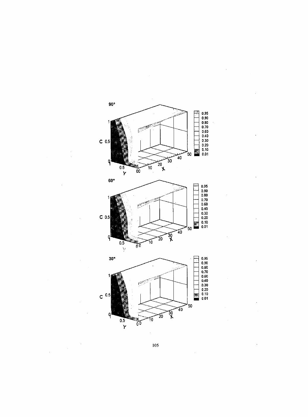
C 0.5
C 0.5
0.95 0.90 0.80 0.70 0.60 0.40 0.30 0.20 0.10 0.01
105
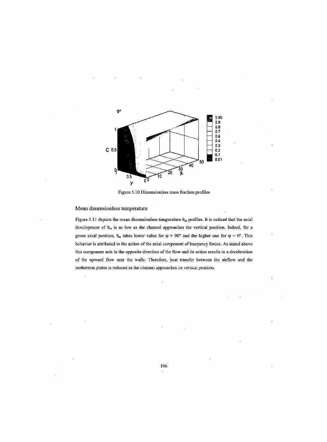
Figure 5.10 Dimensionless mass fraction profiles
Mean dimensionless temperature
Figure 5.11 depicts the mean dimensionless temperature 0m profiles. It is noticed that the axial
development of 9m is as low as the channel approaches the vertical position. Indeed, for a
given axial position, 0m takes lower value for cp = 90° and the higher one for <p = 0°. This
behavior is attributed to the action of the axial component of buoyancy forces. As stated above
this component acts in the opposite direction of the flow and its action results in a deceleration
of the upward flow near the walls. Therefore, heat transfer between the airflow and the
isothermal plates is reduced as the channel approaches its vertical position.
106
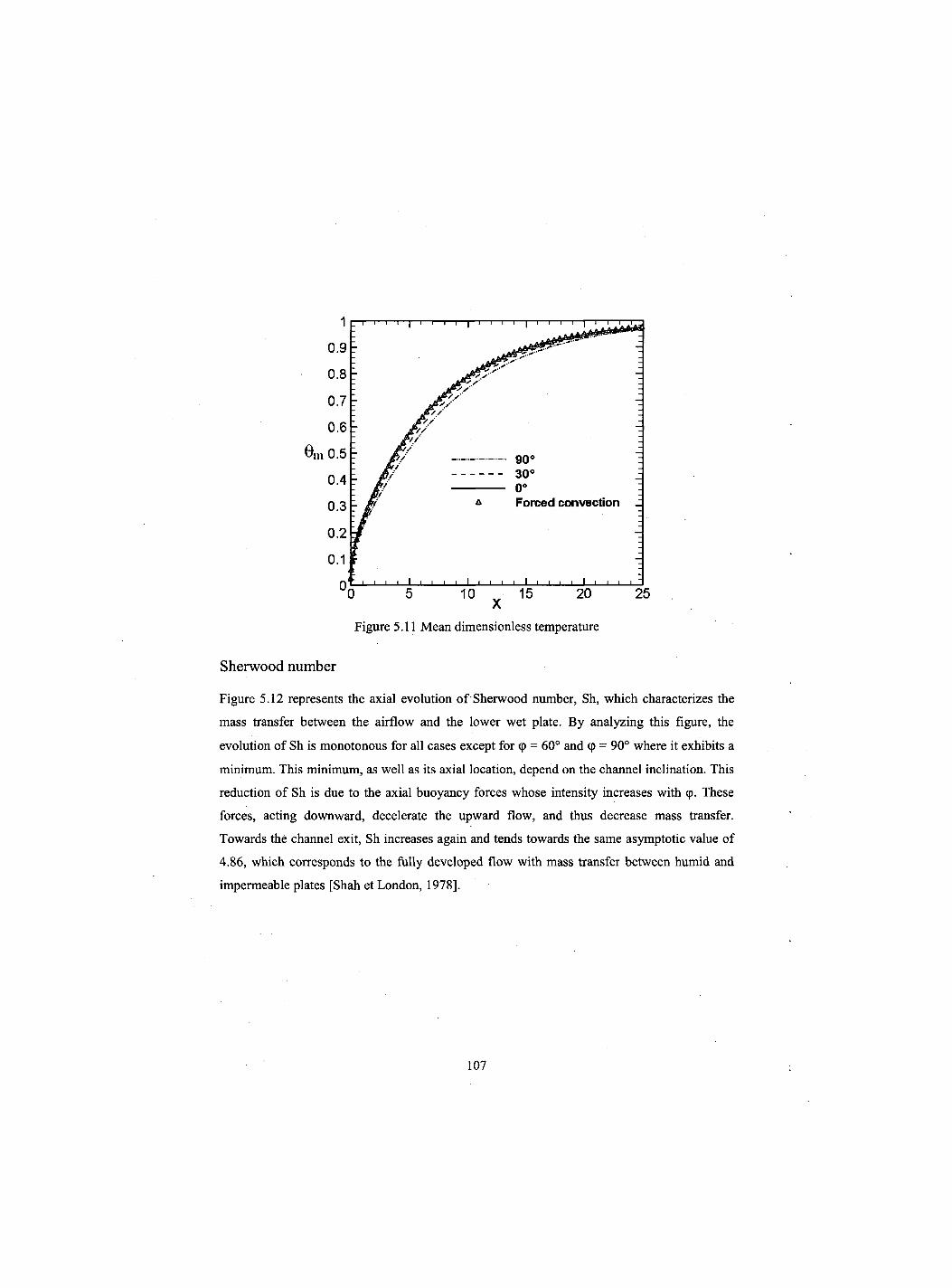
Figure 5.11 Mean dimensionless temperature
Sherwood number
Figure 5.12 represents the axial evolution of Sherwood number, Sh, which characterizes the
mass transfer between the airflow and the lower wet plate. By analyzing this figure, the
evolution of Sh is monotonous for all cases except for cp = 60° and cp = 90° where it exhibits a
minimum. This minimum, as well as its axial location, depend on the channel inclination. This
reduction of Sh is due to the axial buoyancy forces whose intensity increases with cp. These
forces, acting downward, decelerate the upward flow, and thus decrease mass transfer.
Towards the channel exit, Sh increases again and tends towards the same asymptotic value of
4.86, which corresponds to the fully developed flow with mass transfer between humid and
impermeable plates [Shah et London, 1978],
107
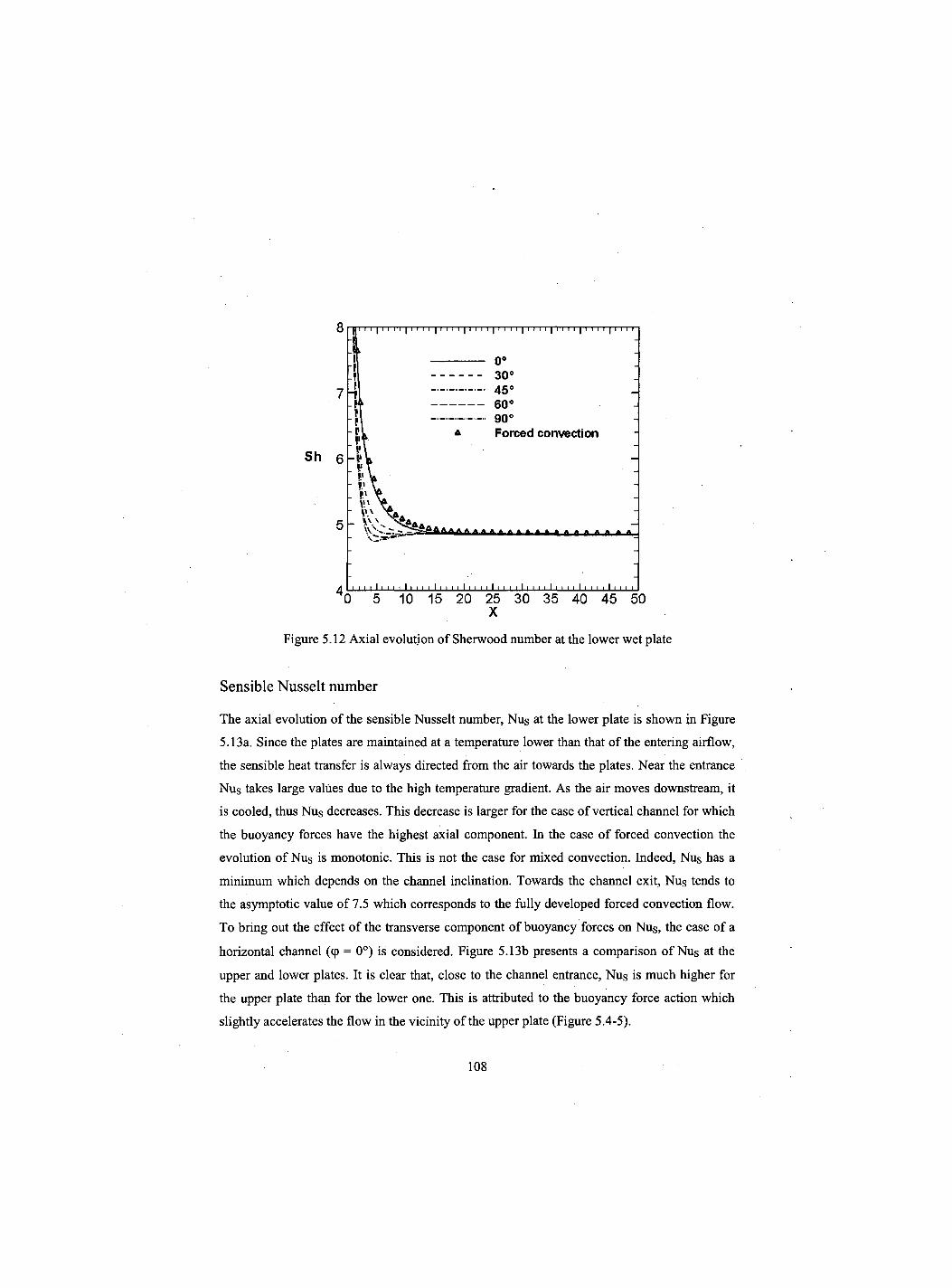
8
7
Sh 6
5
4 0 5 10 15 20 25 30 35 40 45 50 X
Figure 5.12 Axial evolution of Sherwood number at the lower wet plate
Sensible Nusselt number
The axial evolution of the sensible Nusselt number, Nus at the lower plate is shown in Figure
5.13a. Since the plates are maintained at a temperature lower than that of the entering airflow,
the sensible heat transfer is always directed from the air towards the plates. Near the entrance
Nus takes large values due to the high temperature gradient. As the air moves downstream, it
is cooled, thus Nus decreases. This decrease is larger for the case of vertical channel for which
the buoyancy forces have the highest axial component. In the case of forced convection the
evolution of Nus is monotonic. This is not the case for mixed convection. Indeed, Nus has a
minimum which depends on the channel inclination. Towards the channel exit, Nus tends to
the asymptotic value of 7.5 which corresponds to the fully developed forced convection flow.
To bring out the effect of the transverse component of buoyancy forces on Nus, the case of a
horizontal channel ((p = 0°) is considered. Figure 5.13b presents a comparison of Nus at the
upper and lower plates. It is clear that, close to the channel entrance, Nus is much higher for
the upper plate than for the lower one. This is attributed to the buoyancy force action which
slightly accelerates the flow in the vicinity of the upper plate (Figure 5.4-5).
108
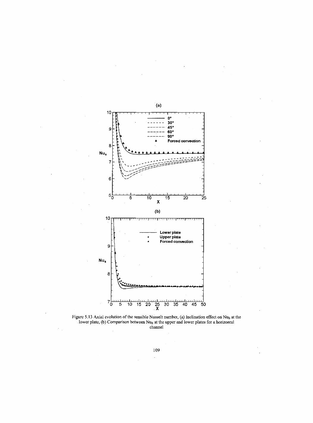
(a)
X
(b)
X
Figure 5.13 Axial evolution of the sensible Nusselt number, (a) Inclination effect on Nus at the lower plate, (b) Comparison between Nus at the upper and lower plates for a horizontal
channel
109
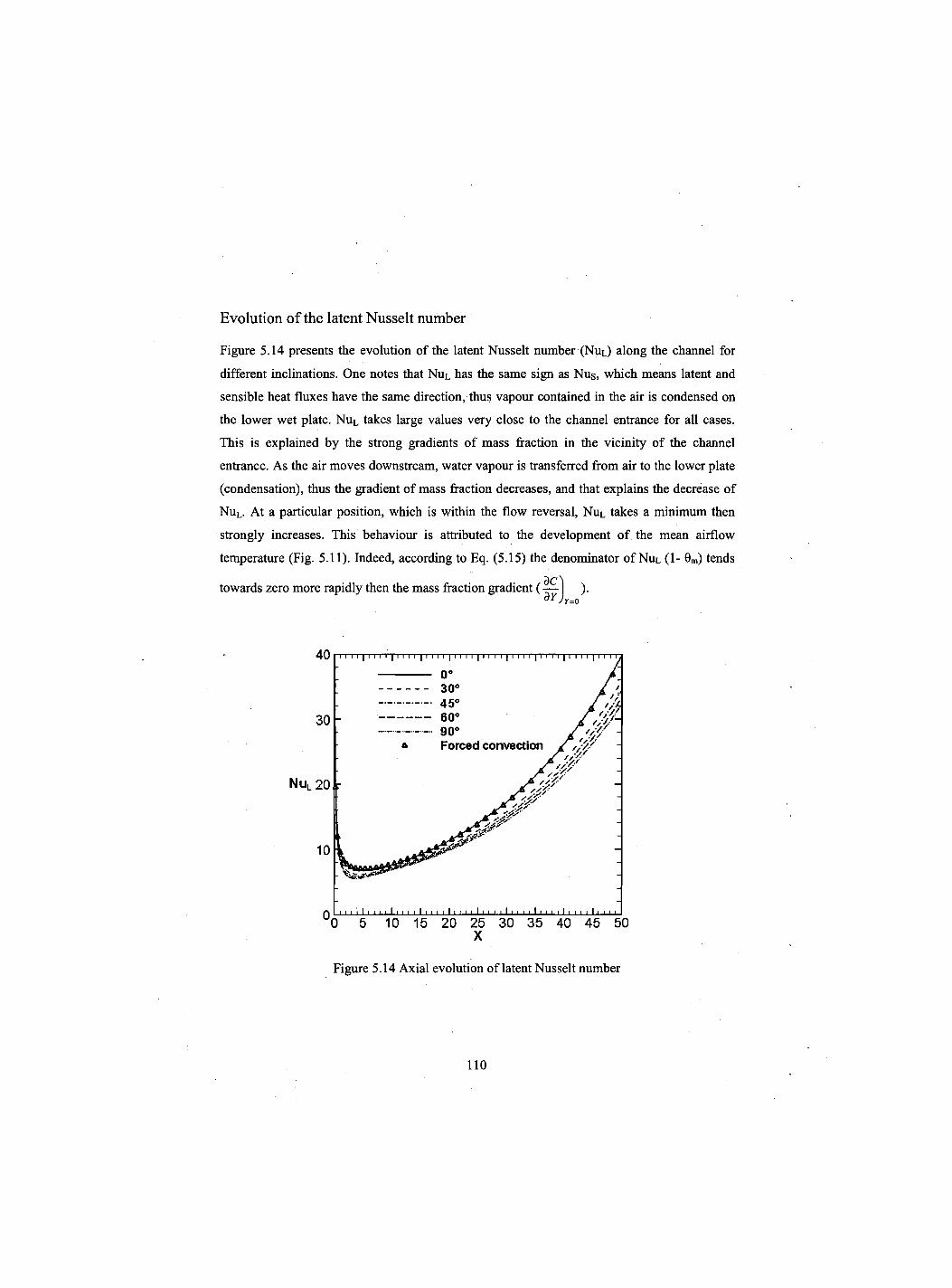
Evolution of the latent Nusselt number
Figure 5.14 presents the evolution of the latent Nusselt number (NUL) along the channel for
different inclinations. One notes that NUL has the same sign as Nus, which means latent and
sensible heat fluxes have the same direction, thus vapour contained in the air is condensed on
the lower wet plate. NUL takes large values very close to the channel entrance for all cases.
This is explained by the strong gradients of mass fraction in the vicinity of the channel
entrance. As the air moves downstream, water vapour is transferred from air to the lower plate
(condensation), thus the gradient of mass fraction decreases, and that explains the decrease of
NuL. At a particular position, which is within the flow reversal, NUL takes a minimum then
strongly increases. This behaviour is attributed to the development of the mean airflow
temperature (Fig. 5.11). Indeed, according to Eq. (5.15) the denominator of NUL (1- 0m) tends
towards zero more rapidly then the mass fraction gradient ( — ). OYJy=0
Figure 5.14 Axial evolution of latent Nusselt number
110
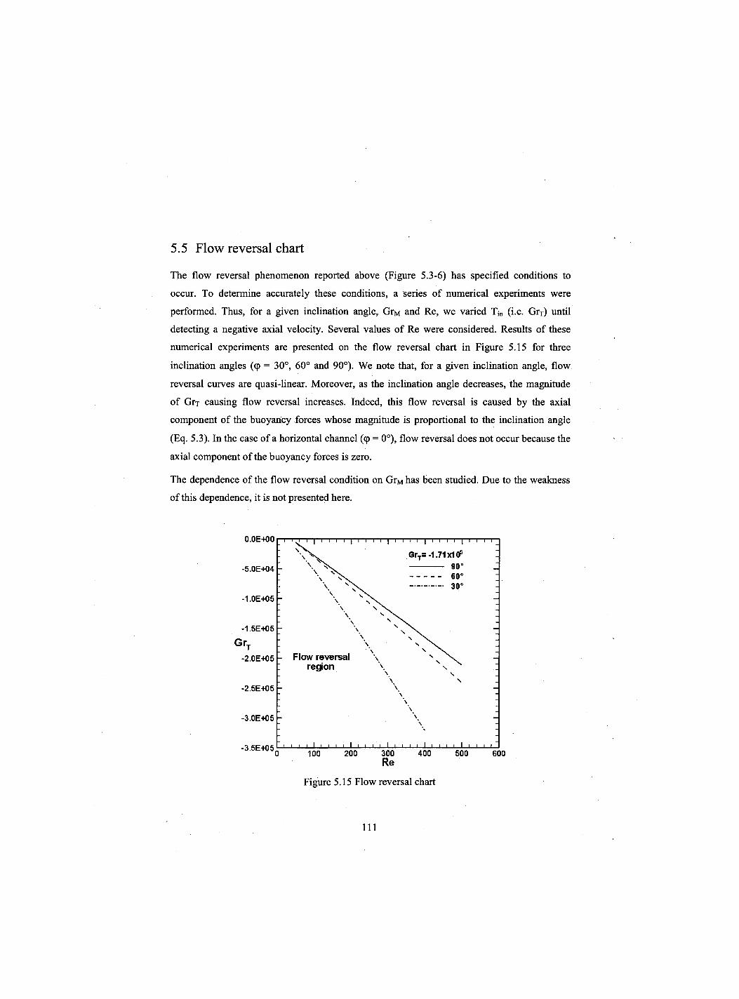
5.5 Flow reversal chart
The flow reversal phenomenon reported above (Figure 5.3-6) has specified conditions to
occur. To determine accurately these conditions, a series of numerical experiments were
performed. Thus, for a given inclination angle, GrM and Re, we varied Tj„ (i.e. Grx) until
detecting a negative axial velocity. Several values of Re were considered. Results of these
numerical experiments are presented on the flow reversal chart in Figure 5.15 for three
inclination angles (cp = 30°, 60° and 90°). We note that, for a given inclination angle, flow
reversal curves are quasi-linear. Moreover, as the inclination angle decreases, the magnitude
of Grx causing flow reversal increases. Indeed, this flow reversal is caused by the axial
component of the buoyancy forces whose magnitude is proportional to the inclination angle
(Eq. 5.3). In the case of a horizontal channel (cp = 0°), flow reversal does not occur because the
axial component of the buoyancy forces is zero.
The dependence of the flow reversal condition on GrM has been studied. Due to the weakness
of this dependence, it is not presented here.
0.0E+00 i i I i i i i I i i i i I i i i i I i i i i I
\ v \ Flow reversal \ N
s region \ N \
\ \
-2.5E+05 \ \
\ \
-3.0E+05 \ \
-3.5E+05 0 i l_l I L
100
1 1 1 I [_J I—I I 1—1 l_l I I I I I I L_l_ 200 300 400 500 600
Re
Figure 5.15 Flow reversal chart
111
The flow reversal charts in figure 5.15 can be expressed by the following correlations:
GrT = 32661.0-877.1 Re GrT =-20816.4-521.5 Re GrT = -17420.1 -455.1Re
<p = 30° for <p = 60°
<p=90P
For GrM = -104 and any combination of the inclination and Reynolds number, these
correlations give the value of Grj which cause flow reversal.
5.6 Conclusion
Heat and mass transfer for mixed convection with phase change in an inclined channel, whose
walls are isothermal and the lower is wetted by a thin water film, was analyzed numerically.
The effects of buoyancy forces and the channel inclination angle were specifically addressed.
The results show that buoyancy forces decelerate the flow near the channel walls and induce
flow reversal in the vicinity of the wet plate. Thus these forces reduce heat and mass transfer.
The importance of this reduction depends strongly on the channel inclination angle. A chart of
flow reversal has been established for different inclination angles. It specifies the values of
Grashof numbers that induce flow reversal for a given Reynolds number and inclination angle.
112
CHAPITRE 6 Conclusion generale et perspectives
Le travail presente dans cette these est une etude numerique de la convection mixte
thermosolutale avec changement de phase dans un canal. Celui-ci est forme de deux plaques
planes, paralleles maintenues a une temperature constante et uniforme. Les deux plaques (ou
juste celle du bas, dans le cas d'un canal incline) sont mouillees par un film d'eau de faible
epaisseur. Un ecoulement d'air humide chaud monte dans ce canal. La modelisation
mathematique de ce probleme physique est basee sur les equations de conservation de la
quantite de mouvement, de l'energie et des especes chimiques. Les proprietes thermo-
physiques sont considerees constantes et 1'approximation de Boussinesq a ete adoptee. Des
hypotheses simplificatrices ont ete introduites et justifiees. Le systeme d'equations simplifie
resultant, qui prend en consideration la diffusion axiale, est resolu nunieriquement par la
methode des volumes finis. Le couplage vitesse-pression est traite par l'algorithme SIMPLER.
Un code de calcul a ete developpe et valide en comparaison avec les resultats numeriques et
experimentaux disponibles dans la litterature.
Les principaux resultats tires de ce travail peuvent etre resumes comme suit:
• Les forces d'Archimede ont un effet important sur les champs hydrodynamique, thermique
et massique. Ainsi, ces forces peuvent causer le renversement de l'ecoulement pret des
parois et par consequent diminuer les transferts de chaleur et de masse dans cette region.
• Nous avons confirme que le transfert par chaleur latente, associe au changement de phase,
est plus important compare a celui par chaleur sensible pour de faibles humidites de l'air a
l'entre du canal, dans le cas de 1'evaporation, ou de fortes humidites en cas de
condensation.
• Le renversement d'ecoulement se produit pour des forces d'Archimede de forte intensite.
Les cellules de renversement ont des formes differentes selon la nature du changement de
phase : evaporation du film liquide mouillant les plaques, condensation de la vapeur d'eau
ou sans changement de phase.
113
• Les conditions d'existence du renversement d'ecoulement ont ete etudiees et ont ete
representees dans des abaques et par des expressions analytiques. Ces abaques et
expressions donnent le nombre de Grashof d'origine thermique critique en fonction du
nombre de Reynolds pour differentes valeurs du nombre de Grashof d'origine massique,
differents rapports de forme et angle d'inclinaison.
• L'inclinaison du canal a un effet important sur les transferts de chaleur et de masse. Ainsi
le renversement d'ecoulement peut avoir lieu pour de grands angles d'inclinaison si les
forces d'Archimede sont significatives.
Les perspectives de developpement de ce travail peuvent etre:
• L'etude du renversement d'ecoulement en 3D.
• L'etude du renversement d'ecoulement en regime turbulent.
• Prendre en compte l'epaisseur du film liquide.
• Adaptation d'un modele plus complet qui prend en compte la variability des proprietes
thermo-physiques en fonction de la temperature et la concentration.
114
LISTE DES REFERENCES
Agunaoun A., Daif A et Daguenet M. (1994) Evaporation en convection forcee d'un film mince s'ecoulant en regime permanent, laminaire et sana onde, sur une surface plane inclinee. Int. J. Heat Mass Transfer, volume 37, n° 18, p. 2947-2956.
Agunaoun A., Kaoua M., Daif A. et Daguenet M. (1996) Evaporation en convection mixte d'un film mince s'ecoulant sur une surface. Revue Generale de Thermique, vololume 35, p.373-385.
Ait Aldjet K. (1988) Evaporation d'eau entre plaques parallele humides sous l'effet d'un ecoulement d'air en convection forcee. Application a 1'evaluation des transferts couples de chaleur et de masse. These de Doctorat-es-Sciences Physique, Universite de Poitiers, Poitiers Cedex, France.
Ait Hammou Z, Benhamou B, Galanis N et Orfi J. (2004) Laminar Mixed Convection of humid Air in a vertical channel with evaporation or condensation at the wall. Int. J. Thermal Sciences, volume 43, p. 531-539.
Ali Cherif A. et Daif A. (1999) Etude numerique du transfert de chaleur et de masse entre deux plaques planes verticales en presence d'un film de liquide binaire ruisselant sur l'une des plaques chauffee. Int. J. Heat and Mass Transfer, volume 42, p. 2399-2418.
An P., Li J. et Jackson J. D. (1999) Study of the cooling of a uniformly heated vertical tube by an ascending flow of air and falling water film. Int. J. Heat and Fluid Flow, volume 20, p. 268-279.
Azizi Y., Benhamou B., Galanis N. et El-Ganaoui M. (2007) Buoyancy effects on upward and downward laminar mixed convection heat and mass transfer in a vertical channel, Int. J. Numerical Methods for Heat and Fluid Flow, volume 17, n° 3, p. 333-353.
Banerjee R. (2007) A numerical study of combined heat and mass in an inclined channel using the VOF Multiphase Model. Numerical Heat Transfer, Part A, volume 52, p. 163-183.
Ben Nasrallah S. et Arnaud G. (1985) Evaporation en convection naturelle sur une plaque verticale chauffee a flux variable. Journal of Applied Mathematics and Physics, Volume 36, p. 105-119.
Bolter L. M. K., Gordon H. S. et Griffin J. R. (1946) Free evaporation into air of water from free horizontal quiet surface. Industrial Engineering Chemistry, volume. 38, n° 6, p. 596-600.
115
Boukadida N. (2000) Contribution a l'etude des transferts couples de chaleur et de masse : application aux phenomenes de 1'evaporation et au sechage convectif. These de Doctorat d'Etat es-Sciences Physiques, Faculte des Sciences de Tunis, Tunis, Tunisie.
Boulama K. et Galanis N. (2004) Analytical solution for fully developed mixed convection between parallel vertical plates with heat and mass transfer. J. Heat Transfer, volume 126, p.381-388.
Boussinesq J. (1903) Theorie analytique de la chaleur. Gauthier-Villars, Paris, France.
Burmeister L. C. (1993), Convective heat transfer. Wiley-Interscience, 2d edition, New York, USA.
Cherif A. S., Dhifaoui B., Ben Jabrallah S. et Belghith A. (2005) Etude de 1'evaporation d'un mince film ruisselant le long des parois actives d'un canal vertical. 12emes Journees Internationales de Thermique, Proceding I, p. 157-160.
Chow L. C. et Chung J. N. (1983) Evaporation of water into laminar stream of air and superheated steam. Int. J. Heat Mass Transfer, volume 26, p. 373-380.
Debbissi C. (2000) Transfert couples de chaleur et de masse accompagnant 1'evaporation par convection naturelle d'un film liquide dans un canal vertical. These de doctorat en sciences physiques, Faculte des Sciences, des techniques et de medecines de Tunis, Tunisie.
Debbissi C., Orfi J. et Ben Nasrallah S. (2001) Evaporation of water by free convection in vertical channel including effects of wall radiative properties. Int. J. Heat Mass Transfer, volume 44, p. 811-826.
Debbissi C., Orfi J. et Ben Nasrallah S. (2003) Evaporation of water by free or mixed convection into humid air and superheated stream. Int. J. Heat and Mass Transfer, volume 46, p. 4703-4715.
Desrayaud G. et Lauriat G. (November 2009) Flow reversal of laminar mixed convection in the entry region of symmetrically heated, vertical plate channels. Int. J. Thermal Sciences, volume 48, n° 11, p.2036-2045.
El Haj Essad M. et Lampinen M. J. (2002) Mathematical modeling of falling liquid film evaporation process. Int. J. refrigeration, Volume 25, p. 985-991.
Faghri A., Faghri M. et Javdani K. (1980) Effect of flow pulsation on laminar heat transfer between two parallel plates. Waerme-und Stoffuebertragung, volume 13, p. 97-103.
Fuji T., Kato Y. et Bihara K. (1977) Expressions of transport and thermodynamic properties of air, steam and water. Sei San Ka Gaku Ken Kuu Jo, Report no 66, Kyu Shu University, Kyu Shu, Japan.
116
Gebhart B. et Pera L. (1971) The nature of vertical natural convection flows resulting from the combined buoyancy effects of thermal and mass diffusion, Int. J. Heat Mass Transfer, volume 14, p. 2025-2050.
Gebhart B., Jaluria Y., Mahajan R. L. et Sammakia B. (1988) Buoyancy-induced flows and transport, Hemisphere Pub. Co., New York, USA.
Gill W. N. Del Gasal E. et Zeh D. W. (1965) Binary diffusion and heat transfer in laminar free convection boundary layers on a vertical plate. Int. J. Heat and Mass Transfer, volume 8, p. 1135-1151.
Guimaraes P. M. et Menon G. J. (November 2004) Combined free and forced convection in an inclined channel with discrete heat sources. Mecanica Computacional Volume XXIII, Bariloche, Argentina.
Gray D. D. et Giorgini A. (1976) The validity of the Boussinesq approximation for liquids and gases. Int. J. Heat Mass Transfer, volume 19, p. 545-551.
Huang C. C., Yan W. M. et Jang J. H. (2005) Laminar mixed convection heat and mass transfer in vertical rectangular ducts with film evaporation and condensation. Int. J. Heat Mass Transfer, volume 48, p. 1772-1784.
Hubbard G. L., Denny V. E. et Mills A. F. (1975) Droplet evaporation: effects of transients and variable properties. Int. J. Heat Mass Transfer, volume 18, p. 1003-1008.
Issa R. I. (1986) Solution of the implicitly discretised fluid flow equations by operator-splitting. Journal of Computational Physics, volume 62, n° 1, p. 40-65.
Jang J. H., Yan W.M. et Huang C. C. (2005) Mixed convection heat transfer enhancement through film evaporation in inclined square ducts. Int. J. Heat Mass Transfer, volume 48, p.2117-2125.
Kassim M. A., Cherif A. S., Benhamou B., Harmand S. et Ben Jabrallah S. (mai 2010) etude numerique et experimentale de la convection mixte thermosolutale accompagnant un ecoulement d'air laminaire ascendant dans un canal vertical adiabatique. ler colloque international Francophone d'Energetique et Mecanique (CIFEM'2010), Saly, 17-19 mai 2010, Senegal.
Laaroussi N., Lauriat G. et Desrayaud G. (2009) Effects of variable density for film evaporation on laminar mixed convection in a vertical channel. Int. J. Heat Mass Transfer, volume 52, n° 1-2, p. 151-164.
Lee K. T., Tsai H. L. et Yan W. M. (1997) Mixed convection heat and mass transfer in vertical rectangular ducts. Int. J. Heat and Mass Transfer, volume 40, p. 1621-1631.
117
Lin T. F., Chang C. G. et Yan W. M. (1988) Analysis of combined buoyancy effects of thermal and mass diffusion on laminar forced convection heat transfer in a vertical tube. J. Heat Transfer, volume 110, p. 337-344.
Lin J. N., Chou F.C., Yan W.M. et Tzeng P.Y. (1992) Combined buoyancy effects of thermal and mass diffusion on laminar forced convection in the thermal entrance region of horizontal square channels. The Canadian Journal of Chemical Engineering, volume 70, p. 681-689.
Machado H. A. et Cotta R. M. (1999) Analysis of internal convection with variable physical properties via integral transformation. Numerical Heat Transfer, Part A, volume 36, p. 699-724.
Mare T., Galanis N., Voicu I., Miriel J. et Sow O. (2008) Experimental and numerical study of mixed convection with flow reversal in coaxial double-duct heat exchangers. Experimental Thermal and Fluid Science, volume 32, p. 1096-1104.
Marschall E. et Moresco L. L. (1978) A variable property analysis of laminar film boiling on vertical plates. Numerical Heat Transfer, volume 1, p. 285-298.
Maters W. G., Madden A. J. et Piret E.L. (1957) Simultaneous heat and mass transfer in free convection. Fluid Mechanics in Chemical Engineering, Volume 49, n° 6, p. 961-968.
Mezaache E. et Daguenet M. (2000) Etude numerique de 1'evaporation dans un courant d'air humide laminaire d'un film d'eau ruisselant sur une plaque inclinee. Int. J. Thermal Sciences, volume 39, p. 117-129.
Mezaache E. et Daguenet M. (2005) Effects of inlet conditions on film evaporation along an inclined plate. Solar Energy, volume 78, p. 535-542.
Nesreddine H. (1997) Influence de proprietes physiques du fluide et de la diffusion axiale dans un ecoulement avec transfert de chaleur a l'interieur d'un tube vertical. These de Doctorat, Universite de Sherbrooke, Sherbrooke, Quebec, Canada.
Nesreddine H., Galanis N. et Nguyen C. T. (1998) Effects of Axial Diffusion on Laminar Heat Transfer With Low Peclet Numbers in the Entrance Region of Thin Vertical Tubes. Numerical Heat Transfer, Part A, volume 33, p. 247-266.
Nguyen C. T., Maiga S. E., Landry M., Galanis N. et Roy G. (2004) Numerical investigation of flow reversal and instability in mixed laminar vertical tube flow. Int. J. Thermal Sciences, volume 43, p. 797-808.
Nield D.A. et Bejan A. (2006) Convection in Porous Media. 3rd ed., Springer, New York, USA.
118
Oulaid O., Benhamou B. et Galanis N. (2010a) Combined buoyancy effects of thermal and mass diffusion on laminar convection in a vertical isothermal channel, Computational Thermal Sciences, volume 2, n° 2, p. 125-138.
Oulaid O. Benhamou B. et Galanis N. (2010b) Flow reversal in combined laminar mixed convection heat and mass transfer with phase change in a vertical channel", International Journal of Heat and Fluid Flow, Vol. 31, pp. 711-721.
Patankar S.V. (1980) Numerical heat transfer in fluid flow. Hemisphere/McGraw-Hill, New York, USA.
Rheault S. et Bilgen E. (1993) Mixed convection heat transfer in open-ended inclined channels with flow reversal. Warme-und Stoffubertragung, volume 29, p. 107-116.
Said S. A. M., Habib M. A., Badr H. M. et Anwar S. (November 2005) Turbulent natural convection between inclined isothermal plates. Computers and Fluids, volume 34, n° 9, p. 1025-1039.
Salah El-Din M. M. (1992) Fully developped forced convection in vertical channel with combined buoyancy forces. Int. Comm. Heat Mass Transfer, volume 19, p. 239-248.
Salah El-Din M. M. (2001) Developing laminar convection in vertical double-passage channel. Heat Mass Transfer, volume 38, p. 93-96.
Shah R. K. et London A. L. (1978) Laminar flow forced convection in ducts. Academic Press, New York, USA.
Shang D. Y. et Wang B. X. (1993) The deviation of heat transfer calculation for laminar free convection of gas due to ignoring the variable thermophysical properties. Warme- und Stoffubertragung, volume 28, p. 33-36.
Siow E. C., Ormiston S. J et Soliman H.M. (2004) A two-phase model for laminar film condensation from steam-air mixtures in vertical parallel-plate channels. Int J Heat Mass Transfer, volume 40, p. 365-375.
Siow E. C., Ormiston S. J. et Soliman H. M. (2007) Two-phase modelling of laminar film condensation from vapour-gas mixtures in declining parallel-plate channels. Int. J. Thermal Sciences, volume 46, p. 458-466.
Tsay Y. L. et Yan W. M. (1990) Binary diffusion and heat transfer in laminar mixed convection channel flows with uniform wall heat flux: extremely thin film thickness. Warme-und Stoffubertragung, volume 26, p. 23-31.
Tsay Y. L., Li T. F. et Yan W. M. (1990) Cooling of falling liquid film through interfacial heat and mass transfer. Int. J. Multiphase Flow, Volume 16, n° 5, p. 853-865.
119
Vachon M. (1979) Etude de 1'evaporation en convection naturelle. These de Doctorat, Universite de Poitiers, Poitiers, France.
Yan W. M. et Lin T. F. (1989) Effects of wetted wall on laminar mixed convection in a vertical channel. J. Thermophysics, Volume 3, p. 94-96.
Yan W. M., Tsay Y. L. et Lin T. F. (1990) Effects of wetted walls on laminar natural convection between vertical parallel plates with asymmetric heating. Applied Scientific Research, volume 47, p. 45-64.
Yan W. M. et Lin T. F. (1990) Combined heat and mass transfer in natural convection between vertical parallel plates with film evaporation. Int. J. Heat Mass Transfer, Volume 33, p. 529-541.
Yan W. M., Lin T. F. (1991) Evaporative cooling of liquid film through interfacial heat and mass transfer in a vertical channel. II. Numerical study, Int. J. Heat Mass Transfer, Volume 34, p. 1113-1124.
Yan W. M., Lin T. F. et Tsay Y. L. (1991) Evaporative cooling of liquid film through interfacial heat and mass transfer in a vertical channel. I. Experimental study, Int. J. Heat Mass Transfer, Volume 34, p. 1105-1111.
Yan W. M. (1993) Mixed convection heat transfer in a vertical channel with film evaporation. Canadian J. Chemical Engineering, volume 71, p. 54-62.
Yan W. M. et Soong C. Y. (1993) Numerical study of liquid film cooling along an inclined plate. Warme- und Stoffubertragung, Volume 28, p. 233-241.
Yan, W. M. (1995) Effects of film vaporization on turbulent mixed convection heat and mass transfer in a vertical channel. Int. J. Heat Mass Transfer, Volume 38, p. 713-722.
Yan W. M. et Soong C. Y. (1995) Convective heat and mass transfer along an inclined heated plate with film evaporation. Int. J. Heat Mass Transfer, Volume 38, p. 1261-1269.
Yan W. M. (1998) Evaporative cooling of liquid film in turbulent mixed convection channels flows. Int. J. Heat Mass Transfer, Volume 41, p. 3719-3729.
Yan W. M. (1999) Mixed convection heat and masse transfer in rectangular ducts rotating about parallel axis. Int. J. Heat Mass Transfer, Volume 42, p. 2955-2965.
Yan W. M. et Lin D. (2001) Natural convection heat and mass transfer in vertical annuli with film evaporation and condensation. Int. J. Heat Mass Transfer, Volume 44, p. 1143-1151.
Wang M., Tsuji T. et Nagano Y. (1994) Mixed convection with flow reversal in the thermal entrance region of horizontal and vertical pipes. Int. J. Heat Mass Transfer, volume 37, p. 2305-2319.
120