The urban real-time traffic control (URTC) system : a …‰ DU QUÉBEC À CHICOUTIMI THE URBAN...
171
UNIVERSITÉ DU QUÉBEC À CHICOUTIMI THE URBAN REAL-TIME TRAFFIC CONTROL (URTC) SYSTEM: A STUDY Of DESIGNING THE CONTROLLER AND ITS SIMULATION MÉMOIRE PRÉSENTÉ COMME EXIGENCE PARTIELLE DE LA MAÎTRISE EN INFORMATIQUE EXTENSIONNÉE DE L'UNIVERSITÉ DU QUÉBEC À MONTRÉAL PAR WANG-LEI JUIN 2006
-
Upload
truongcong -
Category
Documents
-
view
216 -
download
1
Transcript of The urban real-time traffic control (URTC) system : a …‰ DU QUÉBEC À CHICOUTIMI THE URBAN...
UNIVERSITÉ DU QUÉBEC À CHICOUTIMI
THE URBAN REAL-TIME TRAFFIC CONTROL (URTC) SYSTEM:
A STUDY Of DESIGNING THE CONTROLLER AND ITS SIMULATION
MÉMOIRE
PRÉSENTÉ
COMME EXIGENCE PARTIELLE
DE LA MAÎTRISE EN INFORMATIQUE EXTENSIONNÉE DE
L'UNIVERSITÉ DU QUÉBEC À MONTRÉAL
PAR
WANG-LEI
JUIN 2006
UNIVERSITÉ DU QUÉBEC À MONTRÉAL Service des bibliothèques
Avertissement
La diffusion de ce mémoire se fait dans le respect des droits de son auteur, qui a signé le formulaire Autorisation de reproduire et de diffuser un travail de recherche de cycles supérieurs (SDU-522 - Rév.01-2006). Cette autorisation stipule que «conformément à l'article 11 du Règlement no 8 des études de cycles supérieurs, [l'auteur] concède à l'Université du Québec à Montréal une licence non exclusive d'utilisation et de publication ,de la totalité ou d'une partie importante de [son] travail de recherche pour des fins pédagogiques et non commerciales. Plus précisément, [l'auteur] autorise l'Université du Québec à Montréal à reproduire, diffuser, prêter, distribuer ou vendre des copies de [son] travail de recherche à des fins non commerciales sur quelque support que ce soit, y compris l'Internet. Cette licence et cette autorisation n'entraînent pas une renonciation de (la] part [de l'auteur] à [ses] droits moraux ni à [ses] droits de propriété intellectuelle. Sauf ententè contraire, [l'auteur] conserve la liberté de diffuser et de commercialiser ou non ce travail dont [il] possède un exemplaire.»
Il
Abstract
The growth of the number of automobiles on the roads in China has put higher demands on the traffic control system that needs to efficiently reduce the level of congestion occurrence, which increases travel delay, fuel consumption, and air pollution.
The traffic control system, urban real-time traffic control system based on multi-agent (MA-URTC) is presented in this thesis. According to the present situation and the traffic's future development in China, the researches on intelligent traffic control strategy and simulation based on agent lays a foundation for the realization of the system.
The thesis is organized as follows: The first part focuses on the intersection' real-time signal control strategy. It contains the limitations of CUITent traffic control systems, application of artificial intelligence in the research, how to bring the dynamic traffic flow forecast into effect by combining the neural network with the genetic arithmetic, and traffic signal real-time control strategy based on fuzzy control. The author uses sorne simple simulation results to testify its superiority. We adopt the latest agent technology in designing the logical structure of the MA-URTC system. By exchanging traffic flows information among the relative agents, MA-URTC provides a new concept in urban traffic
control. With a global coordination and cooperation on autonomy-based view of the traffic in cities, MA-URTC anticipates the congestion and control traffic flows. It is designed to
support the real-time dynamic selection of intelligent traffic control strategy and the real-time communication requirements, together with a sufficient level of fault-tolerance.
Due to the complexity and levity of urban traffic, none strategy can be universally applicable. The agent can independently choose the best scheme according to the real-time situation. To develop an advanced traffic simulation system it can be helpful for us to find the best scheme and the best switch-point of different schemes. Thus we can better deal with the different real-time traffic situations.
The second part discusses the architecture and function of the intelligent traffic control
simulation based on agent. Meanwhile the author discusses the design model of the vehicle-agent, road agent in traffic network and the intersection-agent so that we can better simulate the real-time environment. The vehicle-agent carries out the intelligent simulation based on the characteristics of the drivers in the actual traffic condition to avoid the disadvantage of the traditional traffic simulation system, simple-functioned algorithm of the vehicles model and unfeasible forecasting hypothesis. It improves the practicability of the whole simulation system greatly. The road agent's significance lies in its guidance of the traffic participants. It avoids the urban traffic control that depends on only the traffic signal control at intersection. 1t gives the traffic participants the most comfortable and direct guidance in traveling. It can also make a real-time and dynamic adjustment on the urban traffic flow, thus greatly lighten the pressure of signal control in intersection area. To
iii
sorne extent, the road agent is equal to the pre-caution mechanism. In the future, the construction of urban roads tends to be more intelligent. Therefore, the research on road agent is very important. AlI kinds of agents in MA-URTC are interconnected through a
computer network. In the end, the author discusses the direction of future research. As the whole system is
a multi-agent system, the intersection, the road and the vehicle belongs to multi-agent system respectively. So the emphasis should be put on the structure design and communication of aU kinds of traffic agents in the system. Meanwhile, as an open and flexible real-time traffic control system, it is also concerned with how to collaborate with other related systems effectively, how to conform the resources and how to make the traffic participants anywhere throughout the city be in the best traffic guidance at aIl times and places. To actualize the genuine ITS wiU be our final goal.
Keywords: Artificial Intelligence, Computer simulation, Fuzzy control, Genetic Algorithrn, Intelligent traffic control, ITS, Multi-agent, Neural Network, Real-time.
iv
Acknowledgement
1 wish to express my sincere gratitude to my research associate director, Prof. Wei Ke-xin who helps and guides me on my academic and professional success. This thesis would not be successful without my research supervisor, Prof. Zhang Hua. She provides me with substantial amount of help and suggestions throughout my work. Special thanks should be given to Prof. Paul for being a member of my thesis committee. 1 thank him especially for his key instruction at the opening speech stage of my thesis and the labor check at the ending stage. l would also like to thank my classmate, Wang Guan for his contributions, to my friends and family who help me with positive affirmation. Thanks ta
my parents for their unending support and eagerness ta love.
y
TABLE OF CONTENTS
CHAPTER 1 1
INTRODUCTION 1
1.1 Research Background and Objectives 1
1.2 Research Significance of the Thesis 2
1.3 Thesis Method 3
lA Thesis Organization 7
CHAPTER 2 10
COMMENT ON THE PROGRESS OF THE TRAFFIC SIGNAL CONTROL
SYSTEM 10
2.1 Introduction of the Intersection 10
2.2 Traffic Signal Terms and Control Evaluation Indexes Il
2.3 Control Types of Traffic Signal.. 14
204 The Types of Urban Traffic Control 15
2.5 The Summary of the Signal Intersection Control System 17
2.6 Intelligent Traffic System Based on Agent 18
2.7 Summary 20
CHA.PTER 3 21
vi
AGENT-BASED INTELLIGENT TRAFFIC SIGNAL CONTROL
STRATEGY 21
3.1 Synopsis of Agent 21
3.1.1 Advantage of Intelligent Agent.. 21
3.1.2 Structure ofTraffic Agent Model 23
3.2 Intelligent Real-Time Traffic Signal Control System Based on Agent24
3.2.1 Analysis of the Control Characteristic at Traffic Intersection 25
3.2.2 Architecture of Intelligent Real-Time Traffic Control System 26
3.3 Study on Intelligent Traffic Signal Control Strategy 28
3.3.1 Major Problem Existing in CUITent Traffic Signal Control Strategies 29
3.3.2 Current Research Situation on Traffic Signal Control. 31
3.4 Real-Time Dynamic Traffic Flow Forecasting Model Based on ..
NN-GA 32
3.4.1 Selection of Forecasting Methods 32
3.4.2 Use High-Order Generalized NN to Forecast Traffic Volume 34
3.4.3 Control Design of Agent Based on NN" 37
3.5 Introduction ofTraffic Signal Control Strategy Based on Fuzzy
Control 40
3.5.1 Brief Introduction of Fuzzy Control Theory 40
VII
3.5.2 Introduction of Fuzzy Control Intersections 42
3.6 Fuzzy Control of Multi-Intersection 44
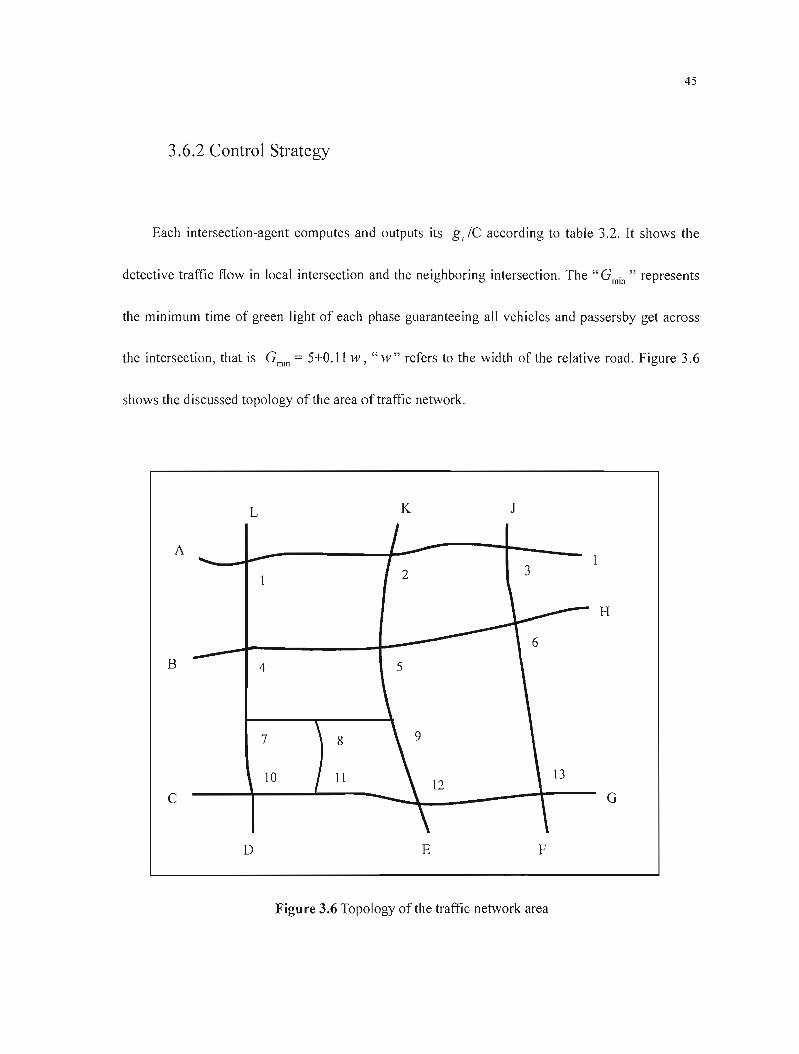
3.6.1 Selective Area of Traffic Network .44
3.6.2 Control Strategy 45
3.6.3 Simulation 49
3.7 Autonomie Decision-Making of Multi-Agent 53
3.8 Integrate Signal Control System with Other Transportation Systems. 56
CHAPTER 4 60
INTELLIGENT TRAFFIC CONTROL SIMULATION RESEARCH 60
BASED ON AGENT 60
4.1 BriefIntroduction ofTraffic Simulation 60
4.1.1 Applying Agent Technology to Do Traffic Simulation 61
4.1.2 Realization ofAgent Technology 62
4.1.3 The Characteristics of Traffic Agent in Cooperation 64
4.2 Simulation Research on the Vehicle Agent.. 65
4.2.1 The Structure Characteristic of the Vehicle Agent.. 66
4.2.2 Functions of the Vehicle Agent 69
4.2.3 Controlling Process of the Vehicle Agent. 77
4.2.4 The InternaI Decision-making Mechanism of the Vehicle Agent.. 79

viii
4.3 Road Agent Study 95
4.4 Summary 96
CHAPTER 5 98
TO ACHIEVE SIMULATION USING OBJECT-ORIENTED
TECI-WOLOGY 98
5.1 The Structural Design of the MA-URTC Simulation System 98
5.2 The Description for the Simulating System 106
5.2.1 System Development Kit 106
5.2.2 Realization of the System's Main Function 107
5.2.3 System 's Communication Management Strategy 110
5.2.4 Output Results of Simulation System 113
5.2.5 Simulation System Maintenance 117
5.3 Simulation Model.. 118
5.3.1 UseCaseModel 119
5.3.2 Simulation Modeling 127
5.4 Summary 135
CHAPTER 6 136
CONCLUSION AND PROSPECTS 136
6.1 Thesis Conclusion 136
ix
6.2 Prospects 139
6.2.1 Traffic Control Strategy 139
6.2.2 Further Research on Intelligent Agent 140
6.3 Epilogue 149
BIBLIOGRAPHY 151
x
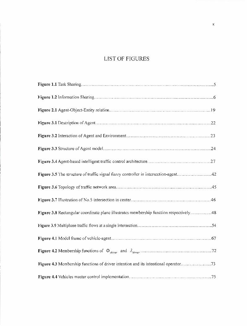
LIST OF FIGURES
Figure 1.1 Task Sharing 5
Figure 1.2lnformation Sharing 6
Figure 2.1 Agent-Object-Entity relation 19
Figure 3.1 Description of Agent. 22
Figure 3.2 Interaction of Agent and Environment. 23
Figure 3.3 Structure of Agent model 24
Figure 3.4 Agent-based intell igent traffic control arch itecture 27
Figure 3.5 The structure of traffic signal fuzzy control 1er in intersection-agent. ..42
Figure 3.6 Topology oftraffic network area .45
Figure 3.7 Illustration ofNo.5 intersection in center 46
Figure 3.8 Rectangular coordinate plane illustrates membership function respectively .48
Figure 3.9 Multiphase traffic flows at a single intersection 54
Figure 4.1 Model frame of vehicle-agent. 67
Figure 4.2 Membership functions of <D driver and Àdriver 72
Figure 4.3 Membership functions of driver intention and its intentional operator. 73
Figure 4.4 Vehicles master control implementation 75

xi
Figure 4.5 Controlling flow chart of vehicle-agent. 78
Figure 4.6 Fuzzy controls ofvehicles following 84
Figure 4.7 Fuzzy membership function dl (unit: Sec) of different driver-type 86
Figure 4.8 Fuzzy membership functions of spacing-margin changes and acceleration 88
Figure 5.1 The hierarchy mode!. 100
Figure 5.2 The p!ug-in mode! of. 101
Figure 5.3 Data interaction diagram 112
Figure 5.4 Use case mode!: Vehicle Control Use Case Package 119
Figure 5.5 Use case model: Road Monitoring Use Case Package 121
Figure 5.6 Use case model: Signal Control Use Case Package 124
Figure 5.7 High-Ievel class diagram ofMA-URTC 128
Figure 5.8 Attribute and method in abstract class of MA-URTC 129
Figure 5.9 High-Ievel UML state diagram of vehicle-agent control 130
Figure 5.10 Orthogonal state diagram ofvehicle-agent driving in simulation system 131
Figure 5.11 Signal control state diagram of intersection-agent: staring event. 132
Figure 5.12 UML collaboration diagram of use case communication: interact driving 133
Figure5.l3 UML collaboration diagram of user formulate/modify map 134
Figure 6.1 Horizontal layering structure of intersection-agent. 143
Figure 6.2 Vertical layering structure of intersection-agent 144
xii
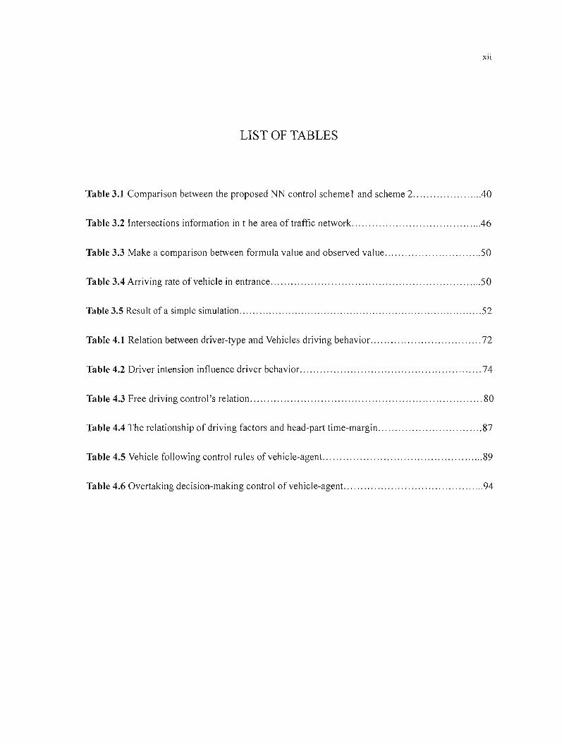
LIST OF TABLES
Table 3.1 Comparison between the proposed NN control scheme 1 and scheme 2 .40
Table 3.2 Intersections information in t he area of traffic network .46
Table 3.3 Make a comparison between formula value and observed value 50
Table 3.4 Arriving rate ofvehicle in entrance 50
Table 3.5 Result of a simple simulation 52
Table 4.1 Relation between driver-type and Vehicles driving behavior 72
Table 4.2 Driver intension influence driver behavior. 74
Table 4.3 Free driving control's relation 80
Table 4.4 The relationship of driving factors and head-part time-margin 87
Table 4.5 Vehicle following control rules ofvehicle-agent. 89
Table 4.6 Overtaking decision-making control ofvehicle-agent. 94
xiii
AI
ACL
ANN
ANN-FC
AOP
BP
CIS
COMET
CPS
DAI
DIA
DTDS
DVMS
FC
FIPA
GA
GDP
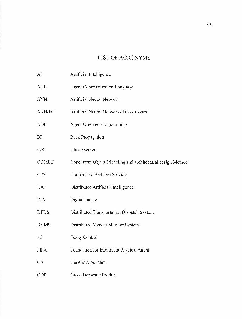
LIST OF ACRONYMS
Artificial Intelligence
Agent Communication Language
Artificial Neural Network
Artificial Neural Network- Fuzzy Control
Agent Oriented Programming
Back Propagation
Client/Server
Concurrent Object Modeling and architectural design Method
Cooperative Problem Solving
Distributed Artificial Intelligence
Digital analog
Distributed Transportation Dispatch System
Distributed Vehicle Monitor System
Fuzzy Control
Foundation for Intelligent Physical Agent
Genetic Algorithm
Gross Domestic Product
00
XIV
GPS
ITS
KQML
MAS
OOP
P2P
PNP
RPC
RMI
RRT
USS
UTFGS
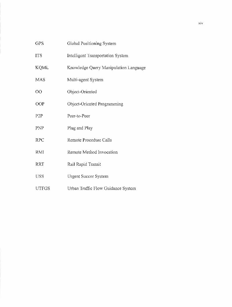
Global Positioning System
Intelligent Transportation System
Knowledge Query Manipulation Language
Multi-agent System
Object-Oriented
Object-Oriented Programming
Peer-to-Peer
Plug and Play
Remote Procedure CaUs
Remote Method Invocation
Rail Rapid Transit
Urgent Succor System
Urban Traffic Flow Guidance System
CHAPTER 1
INTRODUCTION
1.1 Research Background and Objectives
In the large cities with a population over a million in China, the annual direct and indirect
economic loss caused by traffic congestion is about 160 billion Yuan, approximately 3.2% ofGDP.
Moreover, the other negative influences are unimaginable 168]. However, the possibility to rebuild or
enlarge roads in these large cities becomes less and less because of the limited space. So the major
method of solving traffic problem is to organize and control the traffic flow by use of modern
computer, communication and control, etc. making full use of present traffic network, to let it flow
in order.
Now, intelligent transportation system is put fOl'Ward, that is using the latest research products
in fields such as modern computer, electron, communication, artificial intelligence, automobile, etc.
to reform the traditiona! traffic system, achieving intelligent vehicle and road, that is, making
intelligent driver drives intelligent vehicle on intelligent road, finally letting the most vehicles pass
and present traffic situation improve. ITS main Iy contains: intell igent traffic control system,
intelligent vehicle driving system, traffic guidance system, traffic information management system
2
and urgent succor system, etc.
Setting up ITS needs a lot of man power, material and financial resources and it cannot produce
obvious effect in short period. Meanwhile, because of the different traffic condition in each country,
though ITS theory can be used for reference, universal ITS products cannot be achieved. Thus the
goal of this thesis is to make out a real-time traffic control plan, which is better than reconstructing
roads and meets present urban traffic demands.
In urban traffic control, intersection is a basic unit of traffic network, so its research is the
prerequisite and basis of urban traffic research. At present, one intersection takes large quantity of
traffic flow. Signal control is generally adopted. However, this thesis intends to start with real-time
signal control strategy to optimize signal intersection and comment its operating condition by
simulation mode, thus to reduce traffic delay. Later, it gradually improve the whole real-time traffic
control system and realize ITS.
1.2 Research Significance of the Thesis
This thesis is mainly on real-time traffic control and simulation of intersections, which helps
make full use of intersection resources, reduce or eliminate its bottleneck influence in traffic
network, improve the traveling capability and the service level in the whole traffic network.
Traffic engineers from ail countries carrying out research on intersection are widespread and

3
thorough. They have collected more basic database than researching on other traffic facilities. But
its operating analysis is still the most difficult with different analysis methods, which is caused by
the complex traffic-operating mode in intersection 's area. Chinese traffic operating has its special
characteristics from such angles as facility, vehicle performance, traffic content and the drivers, etc.
which is different from other countries, so the operational analysis formulas of data model from
other countries don't fit for Chinese traffic analysis either on accuracy or precision. However, we
think their research products is good for reference, basing of which seek out Chinese intersections
in road system and put forward a set of practical operational analysis.
1.3 Thesis Method
This thesis seeks real-time traffic control strategy from artificial intelligence theory. Intelligent
control is superior to traditional one which is characterized in setting DIA (digital analog) of
controlled objects, however, because of complexity, variability and high non-linearity of the traffic
objects, it is difficult to set up accurate DIA to describe them in addition to uncertainty, so it is
impossible to solve traffic control problem of complex objects using traditional methods. However,
intelligent control, a kind of nonlinear model control method, can do. lt imitates human intelligent
decision. So it is better in solving complex and uncertain problems. Intelligent control contains:
fuzzy control, neural networks, genetic algorithm and expert system, etc.
4
The thesis discusses the traffic control strategy from these aspects. Needs to pay attention
that no technology can be called an absolute plan. They have different applicable ranges and
gradation. What we shall do is to make full use of these technologies, comparing their merits and
demerits, aim at the special details, selected composition, so as to let them work optimally for urban
traffic control. It is the so-called synthesis intelligence out of which an intelligent traffic control
strategy based on agent is drawn. Agent is generally believed to be cognitive, rational, deliberative
and cooperating. [17][52][53] It has three differences at least with the traditional object-oriented
viewpoint.
Agent has a stronger autonomy than object, specially, which decides and carries out actions
requested by other agents by it.
Agent has flexibility, reactivity, pro-activeness and social ability, however standard object
model doesn 't have.
Multi-agent has innate multithread. Each agent has at least one control thread.
Ali the above characters are fit for solving complex traffic control problems. As we study on
real-time traffic control of the whole city, the research on multi-agent systems in distributed
artificial intelligence (DAI) meets the actual demands. Multi-agent system is a loose cooperative
one, which is made up of autonomous intelligent agents. For an overall goal or other different aims,
they share in relative problems and the solving methods to cooperative Problem Solving (CPS).
In the process of solving traffic problem, communication is the base of cooperation. There are
5
mainly two communication models in DAI: shared memory and message passing. We use message
passing to communicate based on distribution and parallel of traffic agents.
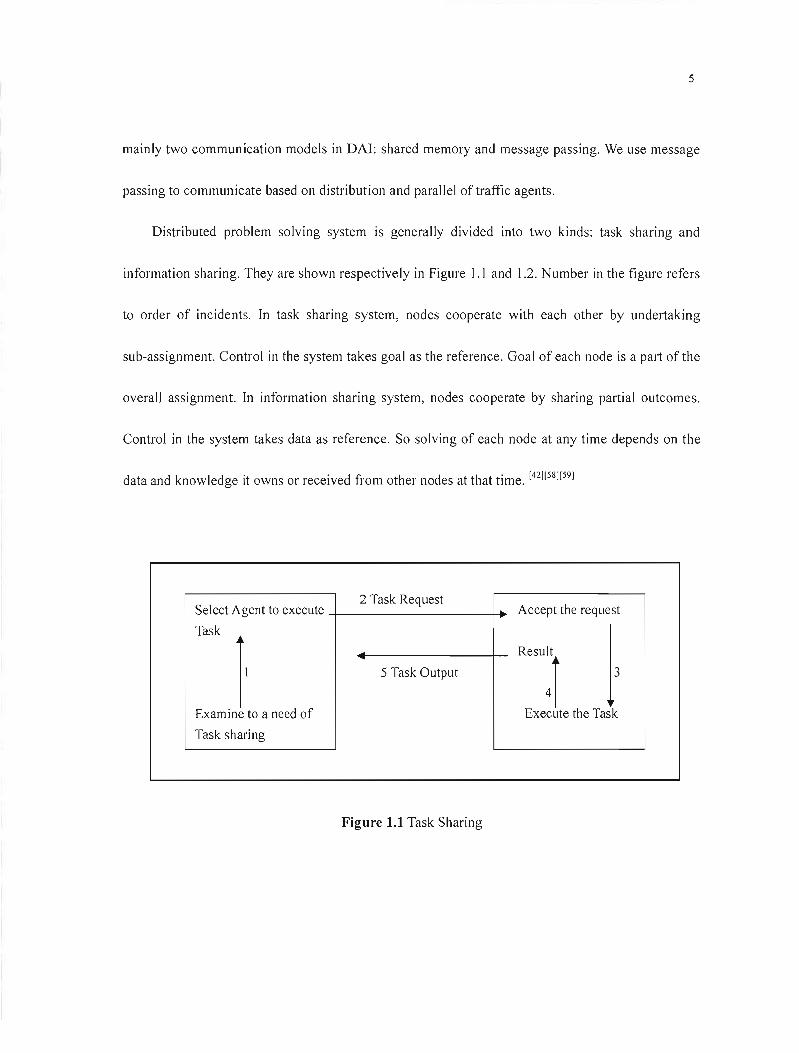
Distributed problem solving system is generally divided into two kinds: task sharing and
information sharing. They are shown respectively in Figure].] and] .2. Number in the figure refers
to order of incidents. In task sharing system, nodes cooperate with each other by undertaking
sub-assignment. Control in the system takes goal as the reference. Goal of each node is a part of the
overalJ assignment. In information sharing system, nodes cooperate by sharing partial outcomes.
Control in the system takes data as reference. So solving of each node at any time depends on the
data and knowledge it owns or received from other nodes at that time. [42][58][591
Select Agent to execute 2 Task Request
Accept the request
Task
lExamine to a need of
5 Task Output Re'"~r 3
Execute the Task
Task sharing
Figure 1.1 Task Sharing

6
2 Non-requests AppraisalSelect i~rested Agent
Information
13
Generate Information Use to Problem
Solving
Figure 1.2 Information Sharing
Task sharing fits for solving tasks with gradations, whiJe information sharing fits for solving
problems whose results of either sub-task interact with each other and part of which needs
multi-purposing. Actually, these two methods are essentially compatible. They put emphasis on
how to solve problem in different solving stages. In our design, task sharing fits for distributed
intersection signal control whiJe information sharing fits for distributed transportation dispatch
system (DTDS) and distributed vehicle monitor system (DY MS) to be developed later. It is
necessary to evaluate these methods before putting them into use.
It is very complex to realize modern control and management of urban traffic. Using computer,
we can simulate actual traffic flow from different gradations and angles; we can understand in
advanee the practieal effeets of traffie management measures and avoid on-the-spot experiment that
cost expensively in a long term. We obtain a lot of data with low cost that could meet conveniently
7
different researchers' needs. Simulation model in this thesis uses agent in a certain degree in order
to adjust to further development.
Shoham puts forward AOP (agent oriented programming) based on OOP (object-oriented
programming). [52] It is an en largement ofOOP. Shoham takes AO P as a special OOP. AOP allows
each agent to own relative environment, knowledge and belief of other agents. AOP allows these
models to own capacity and make promise, etc. An operation is made up of the informant, request,
negotiation and help among each agent. Nowadays, as instruments for developing relative agent are
not mature, we still use OOP to realize simulation system. In the actual simulation design, we use
active object to embody agent as an autonomous entity. So sorne models in simulation system use
agent's theory although it is based on object-oriented technology. We hope this simulation system to
meet such demands as scalability, versatility, reusability and robustness to solving complex
practical traffic problems.
lA Thesis Organization
The rest ofthis thesis is organized into the following chapters:
Chapter 2 generally introduces relative knowledge on signal control and reVlews its
optimization design process. An intelligent traffic system based on agent using real-time traffic
control is put forward to solve traffic problem.
8
Chapter 3 mainly research on agent-based intelligent real-time traffic signal control strategy.
At present traffic control model is generally made by traffic control center. But there exist sorne
probJems with it, such as slow response, bad adjustment, etc. Therefore according to agent's
characteristics and combining developing trend of distributed intelligent control system. This
chapter first discusses how to set up intelligent traffic control system based on agent theory.
Secondly, the chapter discusses the core of traffic signal control strategy by using artificial
intelligence in intersection-agent, as weil as neural network, genetic algorithm, fuzzy control and
expert system. Besides it uses simple simulation to test the control effects. We have to use proper
real-time traffic signal control strategy according to actual situation, because condition of each
urban intersection is different (for example, isolate intersection and correlative "intersection-group",
different intersection of geometry design and intersection having on different traffic function 's
shoulder, etc). Finally, although Chinese real-time traffic control focuses on urban intersection so
far, traffic control in roads cannot be overlooked. As public traffic is the main cause, how to
cooperate with intel! igent control of public traffic becomes the next research key issue.
Chapter 4 eJaborates agent-based intelligent traffic control simulation and explains the
necessity to set up traffic simulation system and the advance of traffic simulation based on agent
theory. In traffic simulation system, it is very important to simulate macroscopic traffic flow and the
microscopie single vehicle. In our simulations, we take vehicle-agent as an intelligent body of
driver and vehicle whose decision style is the actual traffic behavior, embodying a driver's decision.
9
So combining characteristics of fuzzy intelligent control, we discuss vehicle-agent's fuzzy decision
and enlarge the factors that influence it. It differs from former simulation research based on fixed
DIA vehicles. Driving on urban roads differs from driving on highways. Traffic flow on highway
embodies a collective behavior, while vehicles on urban roads embody individual behavior. So we
must make them have autonomous intelligence in traffic network. We believe that more vehicle
modes resembJe actual traffic driving more simulation value they embody. At the same time, In
order to meet the future traffic control need to develop, road agent in traffic network design model
is also mentioned.
Chapter 5 points out that although agent software is superior, at present, there does not exist
good environment for the development of agent commodity software. However, AOP as a software
development method, we can deveJop agent using other software environment. In this chapter, we
discuss using OOP to realize MA-URTC simulation system. Traffic simulation based on agent is a
massive and long-term process, which needs huge manpower and material resources. Java and
MATLAB are used to set up a prototype intelligent traffic simulation environment, meanwhile carry
out simple emulation to laya foundation for further research.
Chapter 6 reviews main contents and conclusions of this thesis, and discusses relative
technological characteristics and puts forward further research direction.
\0
CHAPTER2
COMMENT ON THE PROGRESS OF THE TRAFFIC SIGNAL CONTROL
SYSTEM
In China, the traffic jam phenomenon of the level intersection is becoming more and more
serious. Vehicles shunt, meet and cross repeatedly in intersection area where traffic condition is
complicated. The intersection is a bottleneck that restricts the urban road function. To any city, it is
essential to strengthen the infrastructure construction of urban road, and improve the fast arterial
highway system of the city, but doing weil of the control management of the intersection
undoubtedly has realistic benefits.
2.1 Introduction of the Intersection
The central lines crossing at the same height is called the Jevel crossing. According to the
shape of level crossings, we divide them into T-shaped crossing, Y-shaped crossing, cross crossing,
and loop crossing, etc. The function of level crossing is to commit road network by joining road
together. There are multi-direction traffic flows at the crossing, and the traffic flow is guided by the
traffic 1ight to form the traffic bott1eneck. Moreover, any left-turning or direct driving vehicle,
11
either motor vehicles or non-motor vehicles interlock here, where traffic accident is likely ta
happen. Traffic control model at intersection can be divided into signal control and parking control.
Signal control is ta control the traffic flow with the traffic semaphore while parking control can also
be called priority control, which has priority for the traffic flow on main roads, lets other traffic
flows stop and wait temporarily. [69]
2.2Traffic Signal Terms and Control Evaluation Indexes
The fol!owing is the introduction of sorne special-purpose terms of the traffic signal control:
• Cycle - the whole process that the signal displays.
• Cycle length - the total time that the signal needs ta finish one cycle expressing with
seconds, and using C as the symbol.
• Phases the signal - there are several control states of a traffic semaphore within one cycle,
and each kind of control state is called the signal phase. That is, send signais with the same
color simultaneously ta show time sequence towards one or several rates of traffic flow in
arder within one cycle and open circularly signal lamps in this arder, and each different
compounding signal is called a phase.
• Intervals - the continuous unchanging time that ail signaIs display.
• Time of green lights - the time that the phase of green lights last, using G; (refers ta the
phase of i) as the symbol and unit: Sec.

12
• Effective green light time - the time that the vehicles granted the right-of-way can use
effectively in a given phase. We use second as the unit, and gi as the symbol (to the phase of
i ).
• The traffic light of green signal ratio - the ratio between the effective green light time and the
cycle. gj le is used as the symbol (to i phase).
• Effective red light time - the continuous time that forbid a vehicle to run effectively. We
use second as the unit. It means that cycle deducts the effective green 1ight time that regu lates
the phase. The symbol: ri'
The basic goal of using signal control at level cross mg IS: assign entry lane right-of-way
rationally with light color signaIs, so as to keep crossing in a good order, to reduce or dispel
conflicts totally which may cause traffic accidents, and keep operation of crossing targets best. The
major indexes are as follows:
• Delay time -it refers to the subtraction between the necessary time a vehicle needs to pass by
the leading way of crossing entry in a forbidden position and the time a vehicle needs to use
while be in no hindering position. There are two appraisal yardsticks: one is average delay time,
and the other total delay time.
• Average queuing length - Refers to the average value of the longest length that every lane
needs to queue within one cycle of the signal. The longest length of each lane of queuing refers
to the length when the phase of green lights starts in the driveway.
13
• Numbers of average starts and stops - It refers to times that vehicles stop and restart at the
intersection because of restraint of traffic signal light. The times of stopping and starting are
not only closely related to control parameter, but it is one of the indexes used to weigh the
degree of saturation.
• Traffic capacity - Refers to the total sum of vehicles passing by an intersection way in
entry way in stop line within a given period of time. The traffic intersection capacity is not
merely related to control strategy, but closely related to conditions of the real road (including
the width of leading way, number of driveway, radius of turn, length of turn, and leading way
slope) and traffic conditions (rate of traffic flow, vehicle types, the proportions of turn round
vehicles, speed, non-motor vehicles, pedestrian interference, and the division of roadway
functions, etc). The traffic capacity is an important evaluation index of the degree of saturation
at the intersection. Besides above-mentioned evaluation indexes, there are others such as
traveling time, crowded time, oil consumption, waste gas discharge, etc. As ail these are not in
corn mon use when appraising the isolated level crossing, we do not mention them.
The one that needs pointing out is that these evaluation indexes cannot reach best at the same
time in a traffic control system. For example if we want to improve traffic capacity and reduce the
times of starting and stopping, we have to strengthen signal cycle, but once signal cycle exceeds the
optimum cycle, delay index would turn ineffective. So for the signal control system with many
goals we have to introduce the integrated target. [21] The overall target is expressed with the

14
weighted sum of above-mentioned indexes. The most frequently used overall target is expressed as
follows:
Among them: k; is weighting coefficient, L3
ki = 1, D, S, Qrefer to delay times, parking times ;=1
and traffic capacity respectively. The weight of the three indexes is not fixed, which is adjustable in
line with the change of the traffic flow for the sake of sufficient precedence of certain index, and
adapts to the requirements of real-time traffic.
2.3Control Types ofTraffic Signal
Modern traffic control has many kinds of methods for signal timing. It diversifies from simple
two-phase fixed cycle to complicated multi-phases control. According to the difference of the
control devices adopted, the traffic signal generally has three types.
• Fixed cycle signal control: The cycle length, phase, green-light time and changing intervals,
etc. are confirmed in advance. Signal runs according to the fixed time, and the time and phase
of each cycle is invariable. Depending on the equipment offered, we could use sorne kinds of
timing plans, each kind of which changes alternately within the stipulated time. This kind of
method is relatively suitable for the road with more steady traffic flows, and its fabrication cost
is lower and realistic, however because of the complexity and time variation of the traffic flow,
15
the effect ofthis signal control is relatively bad.
• Half-responsive signal control: this signal control guarantees the maIn arterial highway
keeping green light until the detection installed at the sub-highway detects that there are
vehicles to reach at this moment. The signal displays green light for sub-highway at once after
a proper interval of conversion. Green light time will continue until all vehicles on the
sub-highway get through the intersection or sustain the biggest green light time in arterial
control system. Rationed times of green light of sub-highway must be confined to the
pre-booked time.
• Whole-responsive signal control: All phase of this signal are controlled by the detection. Each
phase general1y stipulates the minimum and the maximum green time, the same as the order of
phase. The cycle length and green light time of this method can make great changes as
requested. Some phases of cycle can be used freely. When detector detects the existence of
traffic flow, it distributes the phase for the traffic flow automatically.
2.4The Types of Urban Traffie Control
Urban traffic control has many ways and classifications. Considering the convenience of
choosing the control method, we divide them according to the span of control. The following is a
brief introduction:
16
• Point control method: Point control method refers to the way that the signal light at the
intersection runs independently. It is suitable for the far-distance adjacent intersection or the
place where arterial control has no effect or the traffic needs to change apparently because of
each phase. It controls independently the cycle and the green signal ratio at intersection
respectively is more effective than others.
• Arterial control method: As the traffic flow characterized in moving successively. When several
nearer intersections on arterial is independent of signal control with each other, the vehicles
from the upstream are likely to meet the red light at the intersection of downstream. Isolated
control method among intersections unavoidably causes stopping frequently. At this time, if
link and control the semaphores of these intersections on the basis of time, it can form a "green
wave belt", thus reduce the stopping times and delay time on the arterial. The main
characteristic of the arterial control is to establish the same cycle and the relative phase
difference of several semaphores. Arterial control is suitable for the intersections that the
distance is not far away, and the traffic flow is heavy. Since the traffic flow will not disperse at
this moment, the control performs more effectively. Arterial control on the basis of control time
can be divided into: simultaneity control, priority control and interaction control; cable control
and non-cable control according to whether it has cable to connect or not; according to the
control strategy, it can be divided into: fixed cycle control, scheme choosing responsive control
and scheme production responsive control.
17
• Area control method: It can also be called coordinated regional control. It adopts coordinated
control to many sets of semaphores on the large area of road network. Because these
semaphores are interrelated, and the timing change of each intersection is more or less related
to other intersection. Area control method is the expansion of the arterial control. It is generally
divided into several sub-regions, which refer to the region that can control with the same cycle.
Tt is made up hierarchically of central controlling machine, sub-region controlling machine and
intersection controlling machine. Central control machine provides with each sub-region the
best cycle. Each sub-region machine is responsible for the optimized computation of the phase
difference and the green signal ratio, intersection control machine adjusts optimally it again.
Area control system is suitable for the structure that many arterial highways interlock together.
Traffic control cannat achieve the anticipated result if the arterial control is adopted. Area
control method can be divided into fixed timing control system and adaptive control system
according ta the control method.
2.5The Summary of the Signal Intersection Control System
The signal control system at intersection can be roughly divided into three research stages:
Early stage refers to the period from 1868, at Westminster crossing of London, when the earliest
traffic signal light appeared, to the 1960s when the countries ail over the world began ta study the
18
coardinated signal linkage and set up simulated mathematics model for different traffic flow
situations at each intersection to solve the optimized problem of signal timing. The second stage,
Britain traffic and traffic road research institute (TRRL) in 1966 began to research and develop the
system TRANSYT (Traffic Network Study Tool), SCATS that Australia began to develop since the
seventies last century (Sydney Coordinated Adaptive Traffic System) and SCOOT
(Split-Cycle-Offset Optimization Technique) system that the system and Britain TRRL began to
study and develop in 1973, etc. Having put forward the concept of " intellectual transportation
system ", that is ITS (Intelligent Transportation System) from 1994 to the present, namely use such
latest research results in the field as modern computer, electron, communication, artificial
intelligence, automobile, etc., to transform the traditional traffic system, to reach the intellectual
faculties on the vehicles and road, its main content includes the following several respects:
Intelligent traffic control system, intelligent vehicle driving the system, USS, UTFGS and traffic
information service system, etc ..
2.6Intelligent Traffie System Based on Agent
In the course of research on the intelligent traffic system, software is the kernel and soul of the
whole system. How to use software to carry out the design development of the traffic engineering,
ta make each system coaperate with each other, is the weak point of carrying out intelligent traffic
19
research at present. The appearance of agent technology offers a new concept for the settlement of
this problem. As the latest software development approach and the results in the artificial
intelligence field, agent is a leap on people's concept. Agent is relatively suitable for the settlement
of the problem on the big complicated system, and has already been applied to the simulation of
battle field of intelligence fields, the operation management of the airport, internet individualized
information service, production of intelligent chemical plant and simulation of the eco-system, etc.
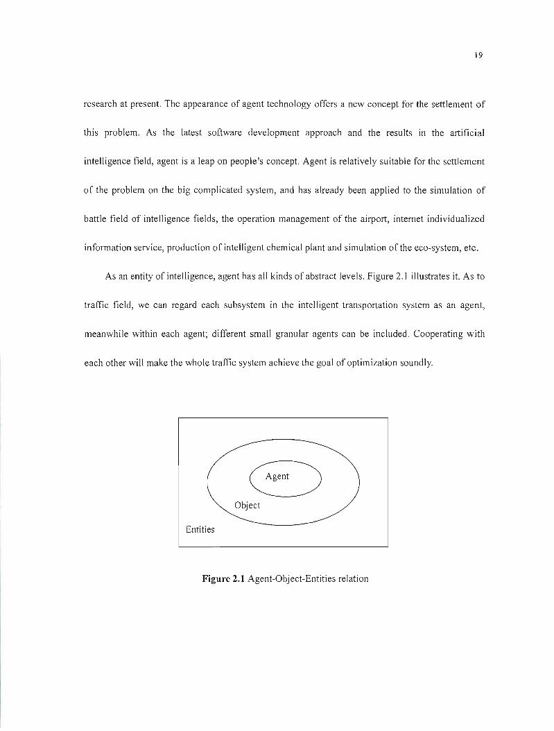
As an entity of intelligence, agent has aU kinds of abstract levels. Figure 2.1 illustrates it. As to
traffic field, we can regard each subsystem in the intelligent transportation system as an agent,
meanwhile within each agent; different small granular agents can be included. Cooperating with
each other will make the whole traffic system achieve the goal of optimization soundly.
8 Object
Entities
Figure 2.1 Agent-Object-Entities relation
20
2.7Summary
The chapter mainly introduces something about the Traffic Control Technology at intersections
and the development of il. We cIaim that we should adopt sorne new techniques rather than use the
old ones in traffic control so as to solve the increasingly serious problems on traffic. As a new
technology for developing software, agent technology is the development of 00 technology. Its
autonomy, activity and collaboration make it convenient for people to describe all kinds of traffic
conditions, and it is further revolution of software developing in computer science. The great effects
that the agent technology has brought are to influence our software developing methods greatly. To
make greater progress in promoting the computer's intelligence, reliability, portability, interaction,
expansibility, etc. are the main software developing purpose in the future. We hope that we can
solve the bottleneck in real-time traffic control in the city by using the agent technology in our
system.
21
CHAPTER3
AGENT-BASED INTELLIGENT TRAFFIC SIGNAL CONTROL
STRATEGY
3.1 Synopsis ofAgent
3.1.1 Advantage of Intelligent Agent
Agent technique is the key in software engineering study and artificial intelligence field. It is a
branch of distributed artificial intelligence and also a development of expert system at unit
intellectualization. Although different groups have different interpretations of Agent, however as a
high-intelligent program, agent may be a module even or a sentence. From the angle of software
engineering, it is a new development of 00. It contains further understanding about software
development, which makes up for the shortcoming on the development of 00. It describes the
active object, human being, social organization and biological existence, etc. Figure 3.1 describes it.
Agent has the following advantages:
• Autonomy: Agent will automatically adjust its behavior and status ln line with outside
circumstance. It has self-management and self-adjustment capabil ity.

22
• Proactive: Agent will take active response to satisfy the outside changes based on its
self-internaI status.
• Reasoning: Agent can reason rationally according to the knowledge and the experience it
already has. Agent intelligence has mainly three components: internai knowledge database,
auto-adapted ability and reasoning capacity based on knowledge database.
• Character: Agent requests consideration of social factors such as security, risk, and good faith,
etc.
1 Coordination
li li Autonomy Reactivity
1 1Communication
li li Cooperation
Proactive Reasoning 1
Figure 3.1 Description of Agent
• Social: Agent is characterized in owing the capability ofCommunicationlCooperation/Coordination
23
with other Agent or human being. While considering the limited power of single Agent,
multi-agent system is applied in practice. Different-functioned Agent works together to solve
one problem. Traffic system is a classical multi-agent system.
3.1.2 Structure of Traffic Agent Model
Agent's being a rapidly developing technique; there are different kinds of advices on Agent
model. But in spite of different individual structure, its Autonomy remains the same. Agent model
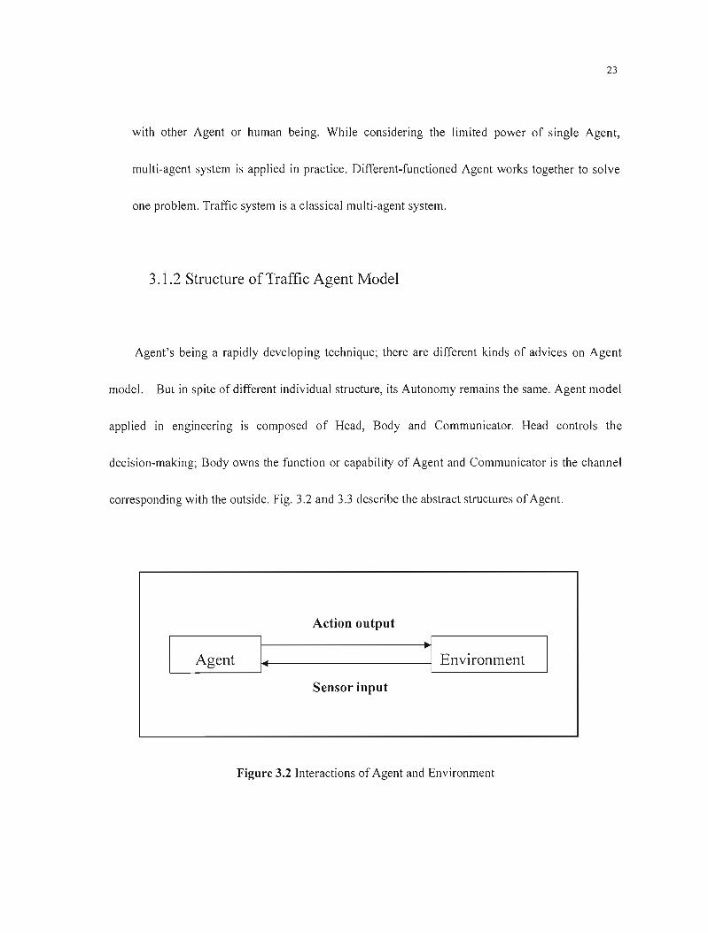
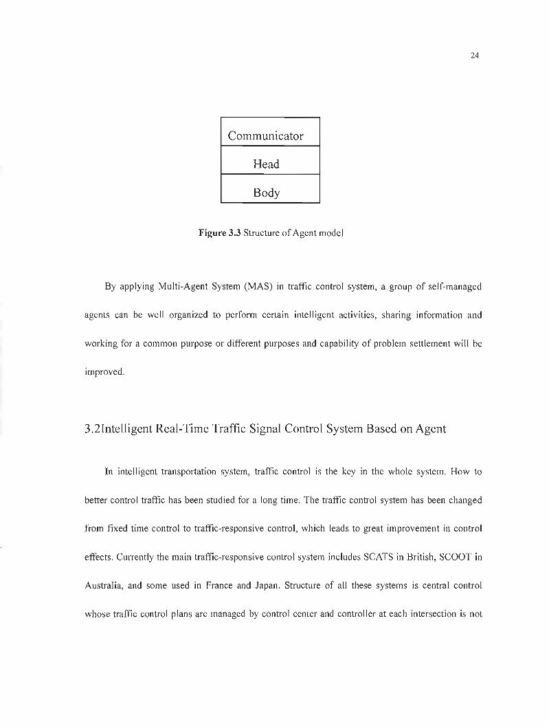
applied in engineering is composed of Head, Body and Communicator. Head controls the
decision-making; Body owns the function or capability of Agent and Communicator is the channel
corresponding with the outside. Fig. 3.2 and 3.3 describe the abstract structures of Agent.
Action output
L--Agent
_ 1....----------·1 Environment
Sensor input
Figure 3.2 Interactions of Agent and Environment
24
Communieator
Head
Body
Figure 3.3 Structure of Agent model
By applying Multi-Agent System (MAS) in traffic control system, a group of self-managed
agents can be weil organized to perform certain intelligent activities, sharing information and
working for a common purpose or different purposes and capability of problem settlement will be
improved.
3.2Intelligent Real-Time Traffie Signal Control System Based on Agent
In intelligent transportation system, traffic control is the key in the whole system. How to
better control traffic has been studied for a long time. The traffic control system has been changed
from fixed time control to traffic-responsive control, which leads to great improvement in control
effects. Currently the main traffic-responsive control system includes SCATS in British, SCOOT in
Australia, and some used in France and Japan. Structure of ail these systems is central control
whose traffic control plans are managed by control center and controller at each intersection is not
25
authorized with active adjustment capability except for collection of traffic data and execution of
control plan. Since the development of the control plan is based on the data from the key
intersections of the designated area, there is no effective consideration of undulation of the traffic
flow at local area. And, as control plan is developed by control center, which causes a complicated
optimization algorithm, huge operand, and low efficiency; along with its inability to adapt the
changeable traffic environments. Therefore, intelligent real-time traffic signal control system based
on agent is put forward in this thesis.
3.2.1 Analysis of the Control Characteristic at Traffic Intersection
Seen from the macroscopic angle, traffic system has characteristics of fluid and wave
transferring, which means what is happening at one intersection will take place at nearby
intersections too after a certain time. One intersection's traffic condition is determined not only by
the traffic flow situation of itself but a1so by its nearby intersections. Based on this, it is more
practical and closer to the fact if traffic control strategies are developed based on the traffic
condition of itself and the nearby, so the traffic control strategies made by traffic control center are
not suitable. Another advantage is that control algorithms and control rules will be much more
simplified and data transmit is going ta be reduced. It leads to higher control efficiency of the
whole system.
26
3.2.2 Architecture of Intelligent Real-Time Traffic Control System
Nowadays, we need to design the new traffic control system according to the characteristics of
the transportation system, which enables it to achieve intelligent control purpose no matter the
macroeconomic regulation or the microscopie adjustment. To satisfy the requirement, we develop
firstly multi-agent urban real-time traffic signal control system that is subsystem of MA-URTC.
This system is designed with three-Ievel architecture. The initial control strategy is going to be
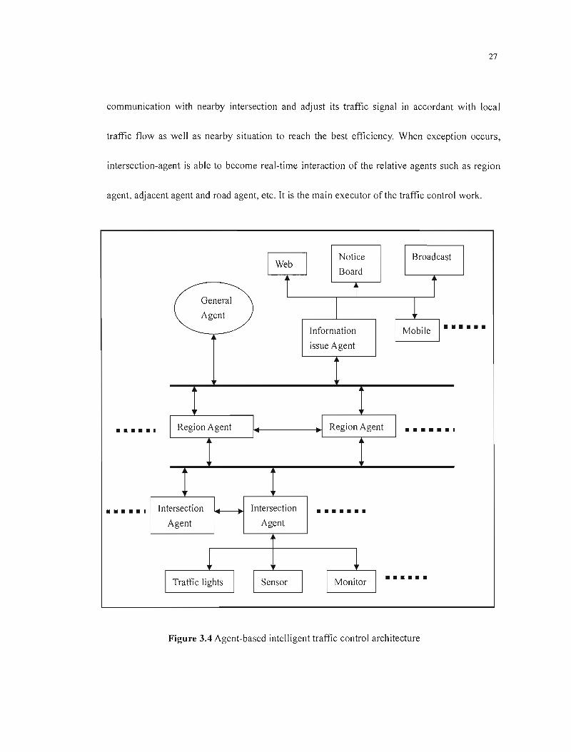
completed by the intersection-agent. Figure 3.4 il1ustrates it. It mainly includes:
• General Agent: Its responsibility is not center control. It has data warehouse only. It monitors
the overall urban traffic environment and makes the traffic control system cooperate with
outside relative system. It has the highest decision-making right.
• Region Agent: Mid-Ievel of the control system. Be responsible for monitoring traffic at
intersections within designated area and force to setup execution model (while sectional
priority control impact overall traffic flow and leading to traffic jam in region); also take care
of emergent issue in the area. Communication between individual regional agents is setup
based on the requirement to exchange information and cooperation.
• Intersection-agent: Located at the bottom level of the control system, it is stored with data
information such as geometry shape of self-intersection, connected road and adjacent
intersection, whose responsibility includes traffic signal control at its intersection, setup on-line
•••••
••••••
•
• • • • • • •
••••••
27
communication with nearby intersection and adjust its traffic signal in accordant with local
traffic flow as weil as nearby situation to reach the best efficiency. When exception occurs,
intersection-agent is able to become real-time interaction of the relative agents such as region
agent, adjacent agent and road agent, etc. It is the main executor of the traffic control work.
Notice Broadcast 1
Web Board
i Î i General
Agent
Information 1
~ Mobile 1··· •••
issue Agent
l
1 Region Agent 1 1 Region Agent 1 •••••• 1 1 1
1ntersection Intersection
Agent Agent
~ 1 1 1Traffic lights Sensor Monitor
1
Figure 3.4 Agent-based intelligent traffic control architecture
28
Because of the application of agent, the system is characterized in:
• High reliability: Any failure of an individual control agent will not cause the whole system shut
down, so it is weil fault-tolerant.
• Good execution: Individual intersection is designed with the capability to adjust its traffic
signal, which helps it make response based on local traffic situations. The real-time response
capability of the system increases which helps to satisfy the compl icated traffic requirements.
Moreover, since each individual intersection is stored with local road geometry structure and
other traffic information, it helps the intersection-agent with more specific signal decision-making.
• Flexibility, scalability, versatility and portability
Traffic control system with the above mentioned structure is more suitable while confronted
with the complex real-time traffic system. It can better adjust to deal with the change of traffic tlow
and any emergency.
3.3Study on Intelligent Traffie Signal Control Strategy
Traffic signal control is a very serious problem in traffic research. A good signal control
strategy can make up for the shortcoming of traffic system 's hardware, can reduce the length of
vehicle queue waiting at the intersection, and reduce unnecessary loss caused by stopping, which is
an important factor in relieving traffic congestion. We have to point out that the intersection signal

29
control has its limitation. Effective signal control is conditioned on the premise that the intersection
transportation demand must be lower than its design capacity. Otherwise, if the intersection is at the
saturation condition, then congestion is inevitable. To solve such problems, we can only de pend on
1imiting the amount of traffic flow, reducing the transportation demand or improving intersection 's
geometry, and enhancing the most greatly traveling capability, etc.
3.3.1 Major Problem Existing in CUITent Traffic Signal Control Strategies
Current traffic-response signal control system such as SCATS and SCOOT has the following
problems:
• Systems like SCATS and SCOOT, etc. were developed in the 1970s. Most of them adopted
traditional optimization control technique. There was little intelligence in the control strategy
and the who le model was out of date.
• Both SCATS and SCOOT adjust signal step by step, which takes longer time, usually about
several minutes. Considering from theoretical angle, they can adjust signal optimization
gradually. But their non real-time control strategies cause a time gap then the traffic flow is not
at the right time. Therefore, they hardly meet present traffic requirements.
• While carries out the area-wide traffic signal control, both systems determine the signal
optimization based on data from critical intersection with the maximum volume of traffic flow,
30
and their system control cycle is the signal cycle of critical intersection. This setup will lead to
illogical timing plans in the whole system and time waste in green light at sorne intersections.
• Actually SCATS system does not belong to a real-time self-adjust control system. ft is
designed to pick up the most optimized one from the existing plans. fts control efficiency is
limited due to limited choices of plan.
• As a model control system, SCOOT needs a complicated control model and a parameter model
to support its operation. But because of the complexity and the changes in traffic, an ideal
model does not operate weil in practice. Furthermore, if the operation model could not adjust
itself in accordance with the outside circumstance, it fails to satisfy the changeable developing
traffic system. In practice, a system works weil at the early stage but its performance becomes
worst after a period of time.
From the 1980s, sorne of our cities imported this kind of system. But due to the existing
problem of these systems and combined with complexity of traffic f10w in China, mixture of all
kinds ofvehicles and interference ofnon-motor and motor vehicles, those systems have not fulfilled
satisfying control effect.
Along with the rapid development of modern technique, computer technique, control theory
and control measures, higher requirements on traffle control technique are put forward. Modern
traffic control technique must be developed with the support of advanced computer technique and
artificial intell igence.
31
3.3.2 CUITent Researeh Situation on Traffie Signal Control
The essential factor in traffic control is control strategy. Traffic system is complex, non-linear
and timing changeable. Seen from macroscopic scope, some traffic phenomena such as arriva] and
departure of traffic flow meet certain mathematic rule and identify certain physicaJ characteristics
such as fluid and wave. But when it goes to microscopie world, especially the individual traffic area,
individual traffic object and the activity of the object at different time, its running characteristic is
various. Therefore, the intensions of describing the actual traffic rule by accurate mathematic mode!
and performing control on traffic can hardly achieve an efficient control effect.
Along with the development of control theory and control strategy, intelligent control
composed with fuzzy theory, artificial neutral network and genetic algorithm replaces traditional
control measure step by step, which is a hot point in current study. Their non-model control raises
the capability to solve complicated system and is proved by good control efficiency. With the
development of control technique, intelligent control technique is applied in traffic control. Related
simulation study proves that intelligent control strategies are more efficient than the traditional
traffic control strategies with fixed time and traffic-response. It is inevitable to apply intelligent
control technique in the deve)opment of traffic control.
The material obtained at present in the traffic signal control research is not sufficient. To do a
better discussion if signal traffic control strategy, our thesis does a study based on artificial
32
intel! igence.
3.4Real-Time Dynamic Traffic Flow Forecasting Model Based on NN-GA
The real-time dynamic traffic distribution is a theoretical basis of ITS. While the premise of
dynamic traffic distribution is real-time forecasting of the traffic volume on-l ine, this wi Il influence
the result of traffic distribution. Therefore, we first study how to real-time forecast the traffie
volume.
3.4.1 Selection of Forecasting Methods
We use NN technology to establish forecast model for adaptive forecast of traffic volume.
Artificial neural network is made up of a lot of simple neuron. It is put forth on the basis of studying
the paral!el architecture of animal brain with human brain as the representative. Theory has verified
that three-neural network can realize any complicated mapping of no-linear problems. So we use
three-neural network that has single hidden layer to carry out adaptive forecasting and modeling.
According to the characteristics of intersection's traffic volume, there are six neural
(T, Qk-I ,Qk-2' q\ ,Q2' Q3) in the input layer, al! of them take "Linear transformation function". The
number of nodes in hidden layer is unknown. They take "alterable non-linear transformation
33
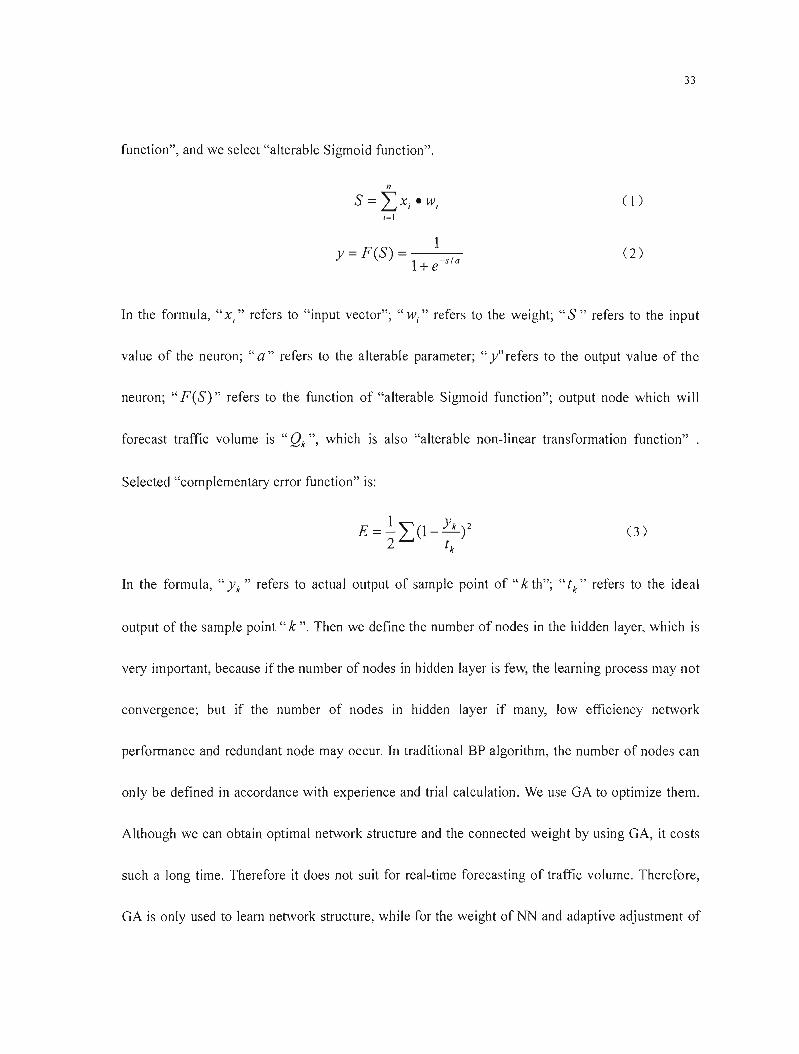
function", and we select "alterable Sigmoid function".
n
S=""xew ( 1) L..J 1 1
i=1
Y - F (S) __1-----,--- (2)- -1+e-s1a
In the formula, "x," refers to "input vector"; "wi " refers to the weight; "S" refers to the input
value of the neuron; "a" refers to the alterable parameter; "y" refers to the output value of the
neuron; "F(S)" refers to the function of "alterable Sigmoid function"; output node which wi"
forecast traffic volume is "Qk ", which is also "alterable non-linear transformation function" .
Selected "complementary error function" is:
0)
In the formula, "Yk " refers to actual output of sample point of" k th"; "tk" refers to the ideal
output of the sample point" k". Then we define the number of nodes in the hidden layer, which is
very important, because if the number of nodes in hidden layer is few, the learning process may not
convergence; but if the number of nodes in hidden layer if many, low efficiency network
performance and redundant node may occur. In traditional BP algorithm, the number of nodes can
only be defined in accordance with experience and trial calculation. We use GA to optimize them.
Although we can obtain optimal network structure and the connected weight by using GA, it costs
such a long time. Therefore it does not suit for real-time forecasting of traffic volume. Therefore,
GA is only used to learn network structure, white for the weight of NN and adaptive adjustment of
34
alterable parameter, we use intelligent neuron mode] of ANN, which can speed up the convergence
rate, satisfy the real-time forecast precision of traffic volume and reduce the running time greatly.
3.4.2 Use High-Order Generalized NN to Foreeast Traffie Volume
The difference of high-order generalized NN and normal NN lies in that the former has two
kinds of structures: one is network-Ievel macroscopic level structure; the other is neuron-Ievel
microscopie level structure. A neuron of normal NN does not have the inner function's handing
ability, but a neuron of high-order generalized NN has intell igent characteristic, that is, its
transference function can be dynamic change and dynamic selection according to system function
requests. Its network training is not only able to adjust the weight immediately but also the
parameter of the neuron's inner transference function. The high-order generalized NN has two kinds
of handling ability: the neuron interior and exterior that suits for the highly non-linear and
time-varying urban traffic flow. The following explains specifïcally.
Network training process:
• Forward computation process: That is gradually computing the input/output condition of
the neuron in every layer from input to output, thus the actual network output can be
obtained. We use GA to obtain the optimal number of nodes in hidden layer and the value
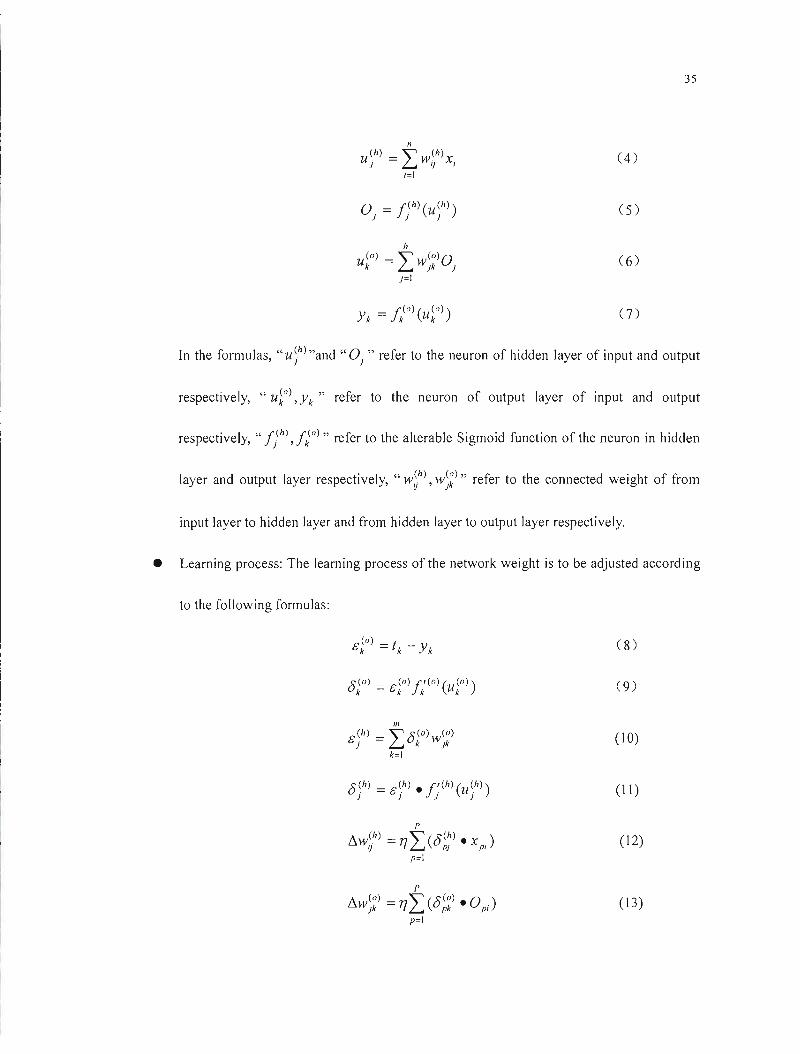
of" a" of alterable parameter. The formulas are as follows:
35
(4)
o = f(h) (U(h») (5)J J J
U~o) = Lh
w;~)Oj (6) J=I
0)
In the formulas, "u ;h) "and" OJ " refer to the neuron of hidden layer of input and output
respectively, "u~o), Yk" refer to the neuron of output layer of input and output
respectively, " ft) ,f?) " refer to the alterable Sigmoid function of the neuron in hidden
layer and output layer respectively, "W~h), w;~)" refer to the connected weight of from
input layer to hidden layer and from hidden layer to output layer respectively.
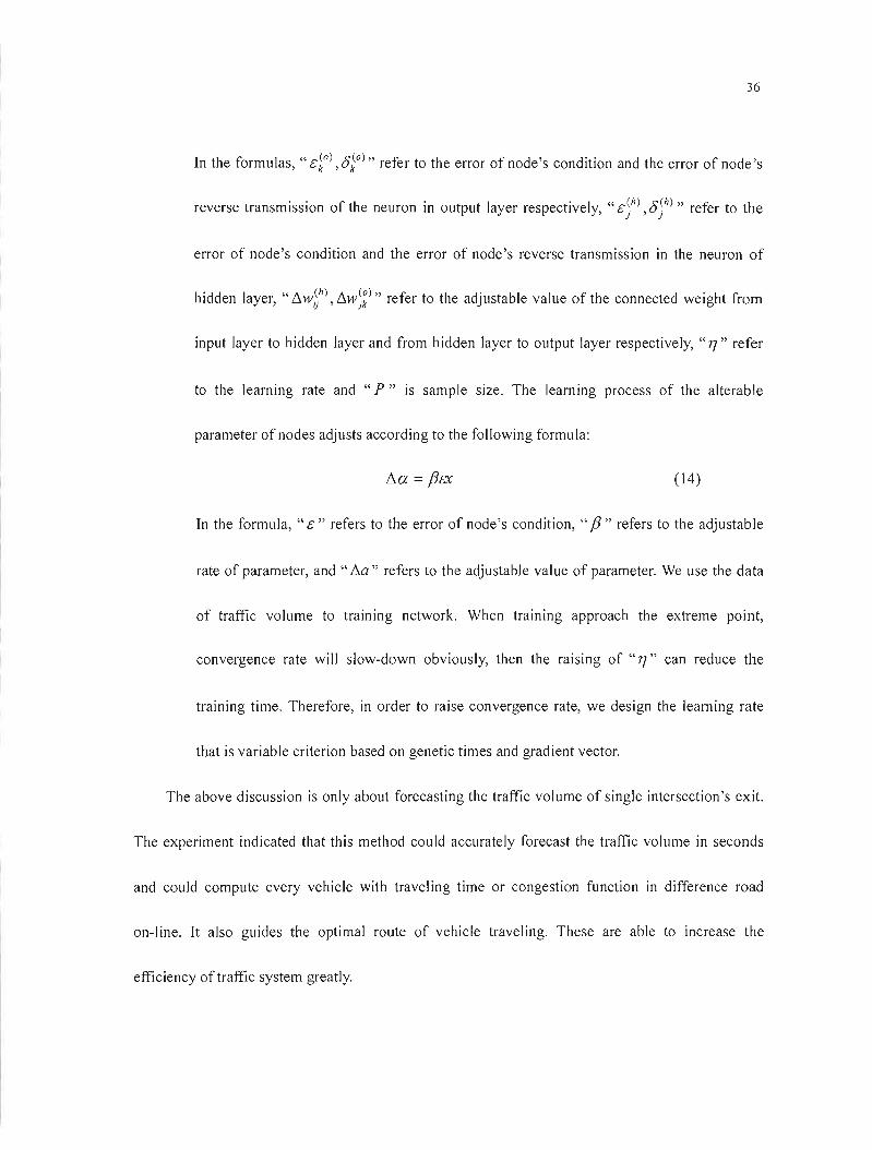
• Learning process: The learning process of the network weight is to be adjusted according
to the following formulas:
(8)
do) _ (0) 1"(0) ( (0»)U k - &k J k uk
(9)
(10)
O(h) = &(h) • f'(h) (U(h») (1 1) J J J J
P
!'1W(h) =n "'(O(h) • X ) (12)U '( L.J Pl pl p=1
p
!'1w(o) =n'" (0(0) • 0 .) (13)Jk '{ L.J pk pl p=1
36
In the formulas, " dO) ,8iO)" refer to the error of node's condition and the error of node 's
reverse transmission of the neuron in output layer respectively, "cjh), 8)h) " refer to the
error of node's condition and the error of node's reverse transmission in the neuron of
hidden layer, "~wt), ~w)Z)" refer to the adjustable value of the connected weight from
input layer to hidden layer and from hidden layer to output layer respectively, "17" refer
to the learning rate and "P" is sample size. The learning process of the alterable
parameter of nodes adjusts according to the following formula:
~a = fJa (14)
In the formula, "c" refers to the error of node's condition, "fJ" refers to the adjustable
rate of parameter, and" 6..a" refers to the adjustable value of parameter. We use the data
of traffic volume to training network. When training approach the extreme point,
convergence rate will slow-down obviously, then the raising of "17" can reduce the
training time. Therefore, in order to raise convergence rate, we design the learning rate
that is variable criterion based on genetic times and gradient vector.
The above discussion is only about forecasting the traffic volume of single intersection's exit.
The experiment indicated that this method could accurately forecast the traffic volume in seconds
and could compute every vehicle with travel ing time or congestion function in difference road
on-line. Tt also guides the optimal route of vehicle traveling. These are able to increase the
efficiency of traffic system greatly.
37
3.4.3 Control Design ofAgent Based on NN
For a complicated multiphase intersection, intersection-agent should be real-time self-adjustment
according to practical traffic conditions, at the same time achieving the optimal phase timings and
phase orders. A signal control strategy of intersection-agent is composed of two self-learning neural
networks and a performance-evaluation unit. Two neural networks are always alternative in the
state of learning or working during the process of self-learning according to the decision of the
performance-evaluation unit on the traffic conditions of intersection.
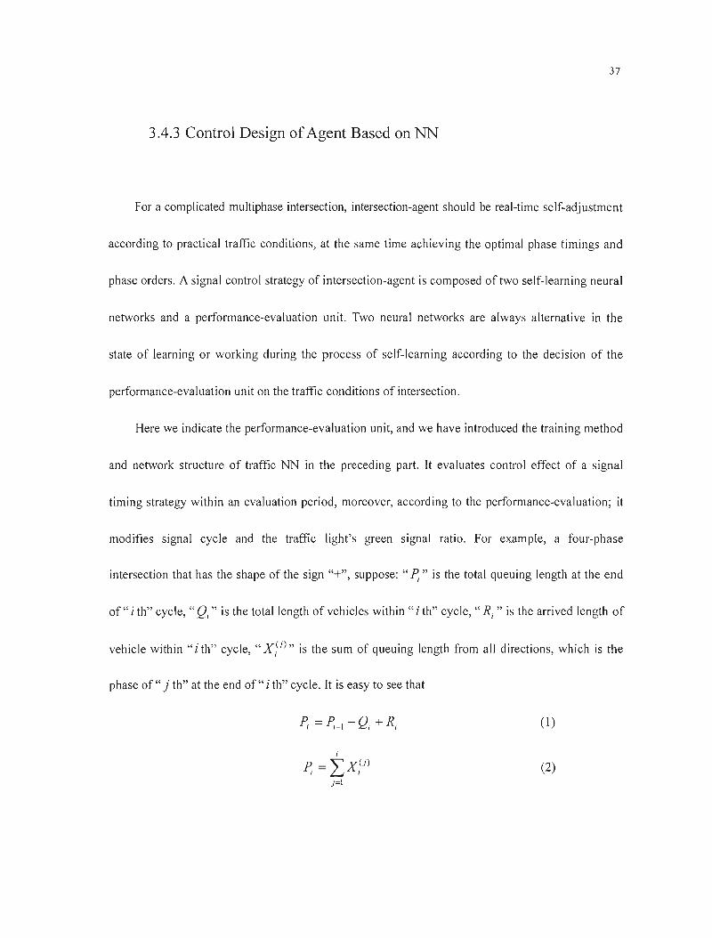
Here we indicate the performance-evaluation unit, and we have introduced the training method
and network structure of traffic NN in the preceding part. It evaluates control effect of a signal
timing strategy within an evaluation period, moreover, according to the performance-evaluation; it
modifies signal cycle and the traffic light's green signal ratio. For example, a four-phase
intersection that has the shape of the sign "+", suppose: " P;" is the total queuing length at the end
of" i th" cycle, "Qi" is the total length of vehicles within "i th" cycle, " Ri" is the arrived length of
vehicle within "i th" cycle, "X i U )" is the sum of queuing length from ail directions, which is the
phase of" j th" at the end of" i th" cycle. It is easy to see that
(1)
i
P 1 =" ~ XU) (2)
1
)=\
38
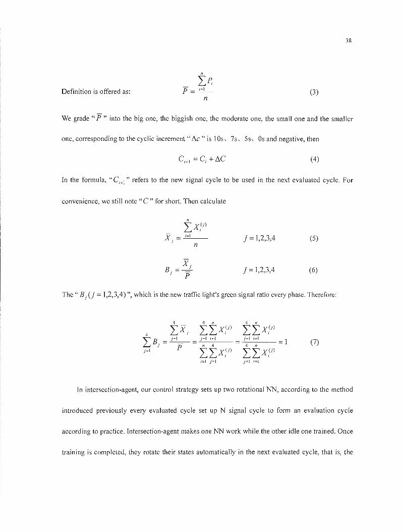
Definition is offered as: (3)
We grade" P " into the big one, the biggish one, the moderate one, the small one and the smaller
one, corresponding to the cyclic increment "!1c" is lOs, 7s, 5s, Os and negative, then
(4)
In the formula, "C;+\" refers to the new signal cycle to be used in the next evaluated cycle. For
convenience, we still note" C" for short. Then calculate
nIX,(J) X =...;..;=...,;.1__ j =1,2,3,4 (5)
J n
X B= -.!. j =1,2,3,4 (6)
J P
The" B) Ci =1,2,3,4) ", which is the new traffie light's green signal ratio every phase. Therefore:
4 4 Il 4 Il
IX) IIX;(J) IIx;U)4
)=1 1=1 )=\ ;=\IB) = )=1 = =: 4 n
=1 (7)Il 4
J=I P IIx,(J) IIX?) ;=\ )=\ J=l 1=1
In intersection-agent, our control strategy sets up two rotational NN, according to the method
introduced previously every evaluated cycle set up N signal cycle to form an evaluation cycle
according to practice. Intersection-agent makes one NN work while the other idle one trained. Once
training is completed, they rotate their states automatical1y in the next evaluated cycle, that is, the
39
original working NN changes into an idle state which is trained according to the related parameters
while the other turns to control signal. Two NN wok and learn alternatively so that the agent's
controller effect reaches the optimization gradually. But we find that with time going on, do
repeatedly, the training samples will be more and more and it will be more and more difficult to
train NN. In order to avoid "samples explosion" we use "samples interception", that is, stipulate in
advance the training scale of samples according to practical request, and then eliminate the old
samples one by one with the new ones in a way of" the order shifting ". Finally, through learning
and training, two NN wi11 be satisfactory and one of them may be backing up which raises the
fault-tolerance of the intersection-agent.
In order to testify the controlling effect of the self-Iearning control scheme (we cali it Scheme
1) in neural network, we carried out a simple simulation in which we compared the effect of it with
the learning-from the traffic police's experience scheme (we cali it Scheme 2), and the results are
shown in Table 3.1. We can see that the difference between these two schemes is not great when the
traffic is not crowded. However, when the traffic becomes more and more crowded, the difference
becomes greater. It proves that as the NN controlling strategy mentioned in this thesis is capable of
self-Iearning and step-by-step optimizing, its controlling effect is superior. In the test, we used the
stochastic number that is obedient to binomial distribution to describe the arrivai of the vehicles,
and we supposed that the saturation point of the vehicles on the straight lane is 1500 per hour; the
saturation point of the Jeft-turning and right-turning vehicles is 1200 per hour. When ail these

40
vehicles get to the intersection, 30% of them turn left, 50% of them go straight ahead, and the left
20% turn right. The average number of the vehicles at each entrance is equivalent to each other, and
the lost time of green light in each traffic lights period is 8 seconds. The simulation lasted for 50
thousand signal periods.
Volume of traffic Average queue (Vehicle/T) Volume of traffic Average queue (Vehicle/T)
in intersection Scheme ] Scheme 2 in intersection Scheme 1 Scheme 2
< 800 <3.9 < 3.9 1440 30.04 38.34
880 4.73 5.12 1520 36.71 46.97
960 5.45 6.97 1600 43.57 55.41
1040 8.14 10.33 ]680 50.86 64.10
1120 Il.28 14.87 1760 57.94 73. ]9
]200 ]4.98 ]9.53 1840 66.83 89.36
1280 19.27 24.61 1920 77.45 112.53
1360 24.26 31.29 2000 89.26 139.75
Table 3.1 Comparison between the proposed NN control scheme 1 and scheme 2
3.5Introduction ofTraffic Signal Control Strategy Based on Fuzzy Control
3.5.1 Brieflntroduction of Fuzzy Control Theory
Human beings use a fuzzy language to describe the outside information. For example, "big
and small' "quick and slow" "hot and cold" etc. aIl ofwhich could not be demarcated clearly by a
precise mathematical language. The fuzziness of human language cause a certain human's
41
intelligence not to describe precisely a model science based on mathematics. In 1965, Prof.
L.A.Zedeh put forth the fuzzy theory for the first time. The fuzzy theory based on strict
mathematics foundation describes the human fuzzy language information, the computer using it is
able to process the fuzzy language question, and moreover, it has erected a bridge for artificial
intelligence and modern science. English Mamdani and Assilian are forerunners that apply the
fuzzy theory to the control domain.
• The characteristics offuzzy control system
~ The fuzzy control system has better stability and robustness.
~ It is easy to design a fuzzy control 1er and the debugging is also convenient
~ We do not have to establish a precise mathematic model for control system. Thus it is
suitable for a complicated traffic control system that is usually variable, non-I inear,
and multi-perturbation. Considering the actual situation, an experienced traffic
pol iceman can effectively unblock the stream of vehicles under ail kinds of traffic
conditions; therefore we established the fuzzy control rule coming from experts
(traffic police's experience) in intersection-agent to carry out the automatic control to
the stream of vehicles.
• Mechanism of fuzzy controller
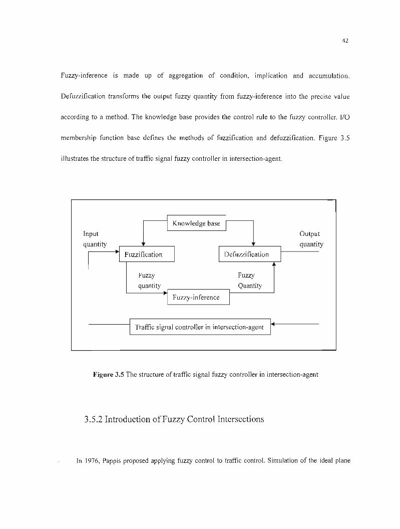
Fuzzy controller is composed of fuzzification, fuzzy-inference and defuzzification.
Fuzzification transforms the precise value that is assigned or feedback into the fuzzy quantity.
42
Fuzzy-inference is made up of aggregation of condition, implication and accumulation.
Defuzzification transforms the output fuzzy quantity from fuzzy-inference into the precise value
according to a method. The knowledge base provides the control rule to the fuzzy controller. 1/0
membership function base defines the methods of fuzzification and defuzzification. Figure 3.5
illustrates the structure oftraffic signal fuzzy control1er in intersection-agent.
1 1
1
Knowledge base 1
putIn Output
uantityq ~I
tyquanti
·1 Fuzzification Defuzzification 1 1 1
Fuzzy Fuzzy
quantity Quantity
1 Fuzzy-inference 1
1 1
1 Traffic signal controller in intersection-agent 1
Figure 3.5 The structure oftraffic signal fuzzy controller in intersection-agent
3.5.2 Introduction ofFuzzy Control Intersections
In 1976, Pappis proposed applying fuzzy control to traffic control. Simulation of the ideal plane

43
crossing indicated that this fuzzy control algorithm reduced the average 7% of the vehicular delay
compared with the traditional control algorithm reduction vehicles in intersection. [351 Hereafter,
although many researchers applied the fuzzy technology in the traffic control, there still existed many
deficiencies in the control strategy utilization and understanding, which include:
• Research is limited in one-direction flow in a simple intersection.
• Most of them only consider the two-direction straight-going traffic flow but ignore the impact
of left-turning flow.
• While using fuzzy control, selection of fuzzy variable is too simple without integrating the
different changes of traffic flow in different driving directions and individual lanes.
• The decision-making process cannot manifest completely the actual condition of traffic signal
control as cornpared with a traffic police directs.
• Single selection of signal phase results with poor flexibility, though sorne systems are designed
with multi-phase control strategy, they do not have flexible phase switch capability.
To solve the existing problems caused by the application of current fuzzy technique,
considering the actual character of traffic signal control, we put forward an intell igent traffic signal
control strategy, Multi-Agent self-organized strategy. It is designed to perform fuzzy traffic control
at multi-intersection in urban traffic network first and then go on with the further study on signal
control strategy at single intersection. Tt is put forward to provide helpful idea on the research of
intelligent control technique to solve traffic control problems.
44
3.6Fuzzy Control of Multi-Intersection
At present the traffic fuzzy control research object is mostly limited in the isolated single road
intersection. Tt is rare for research ing the multi-intersection. But in fact, each neighboring
intersection is mutually coupled with each other, especially in the urban economic and cultural
centers. We discuss the fuzzy signal control strategy of multi-intersection based on the urban traffic
network and with universality.
3.6.1 Selective Area ofTraffic Network
Fuzzy control strategy discussed here is set up at intersection-agent that receives parameter,
like signal cycle, etc., from other agents then controls local traffic lights in line with real-time traffic
flow. Cross intersection and T intersection are the most popular ones.3-dimentional intersection is
used mainly at multi-branch intersection. Right-turn vehicles of any direction is not controlled by
signal lights at a cross intersection. For the sake of clear description of control strategy, we setup
two phases: the East-West phase and the North-South phase. Concerning y intersection, it can be
classified as T intersection by exaggerating the angle to 180 degree.
45
3.6.2 Control Strategy
Each intersection-agent computes and outputs its g,IC according to table 3.2. It shows the
detective traffic flow in local intersection and the neighboring intersection. The" G min " represents
the minimum time of green light of each phase guaranteeing ail vehicles and passersby get across
the intersection, that is G min = 5+0.11 w, "w" refers to the width of the relative road. Figure 3.6
shows the d iscussed topology of the area of traffic network.
K JL
A
32
H
B 4 5
7
1310 12
C G
o E F
Figure 3.6 Topology of the traffic network area
46
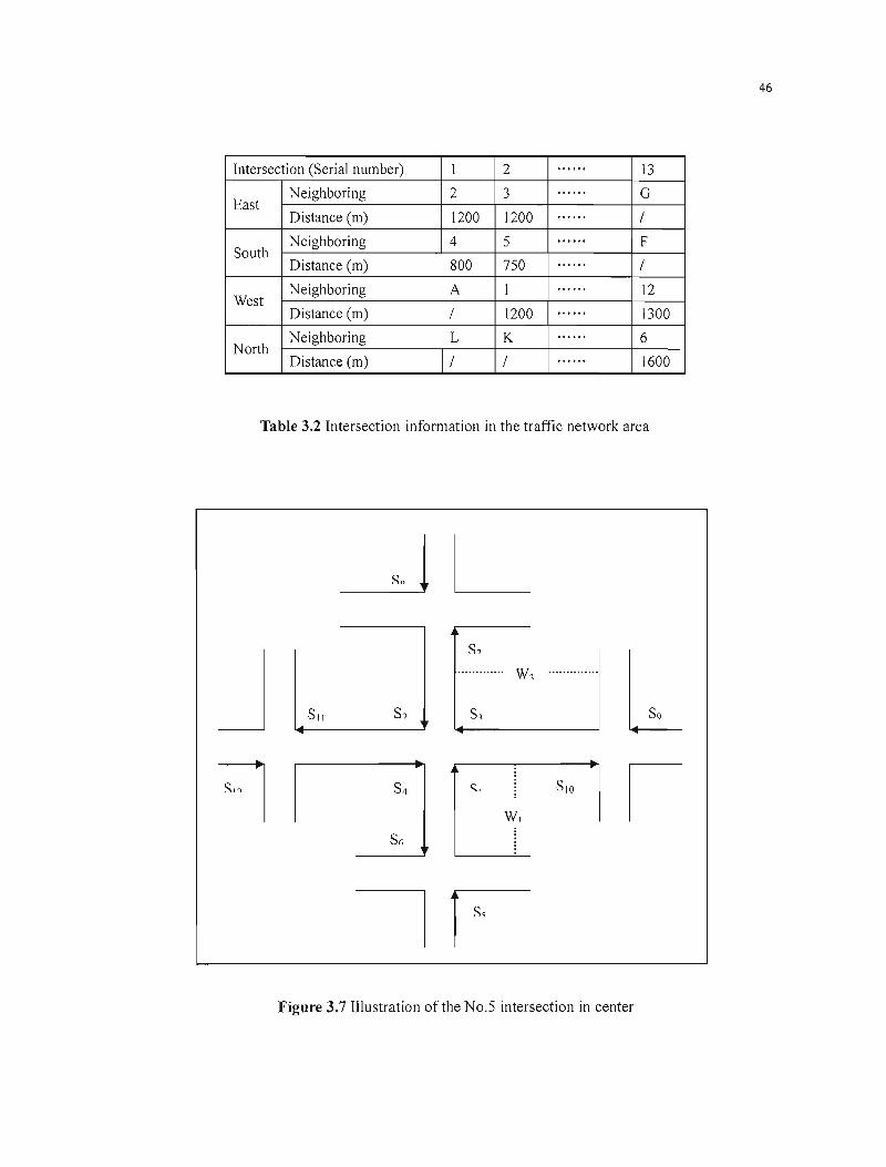
......Intersection (Seriai number) 1 2 13
......Neighboring 2 3 G East ......Distance (m) 1200 1200 /
......Neighboring 4 5 F South ......Distance (m) 800 750 /
......Neighboring A 1 12 West ......Distance (m) / 1200 1300
......Neighboring L K 6 North
Il ••••Distance (m) / / 1600
Table 3.2 Intersection information in the traffic network area
~ L
J s,
l............. ..............W1
Sil s? S1
S4 ç;, SIO
W1
S"
~ 1
1 ~ Figure 3.7 Illustration of the No.5 intersection in center
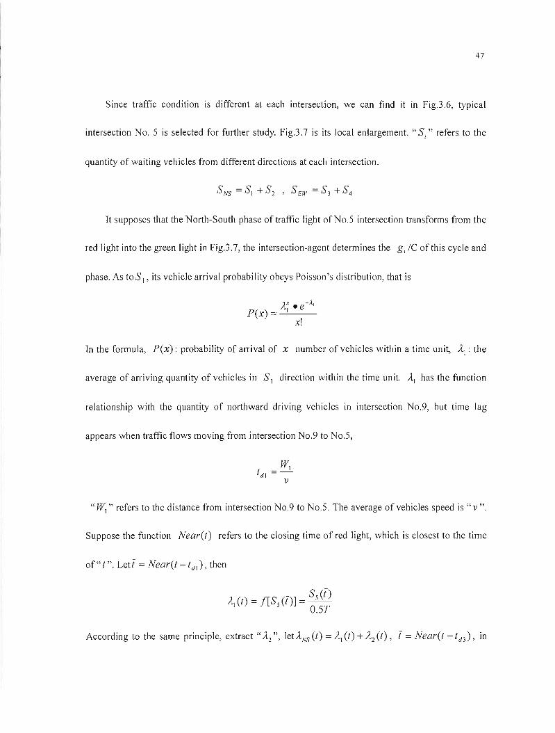
47
Since traffic condition is different at each intersection, we can find it in Fig.3 .6, typical
intersection No. S is selected for further study. Fig.3.7 is its local enlargement. "Si" refers to the
quantity ofwaiting vehicles from different directions at each intersection.
It supposes that the North-South phase oftraffic light ofNo.S intersection transforms from the
red light into the green light in Fig.3.7, the intersection-agent determines the g, le ofthis cycle and
phase. As toS" its vehicle arrivai probability obeys Poisson's distribution, that is
In the formula, P(x): probability of arrivaI of x number of vehicles within a time unit, ~: the
average of arriving quantity of vehicles in SI direction within the time unit. AI has the function
relationship with the quantity of northward driving vehicles in intersection No.9, but time lag
appears when traffic flows moving from intersection No.9 to No.S,
"WI " refers to the distance from intersection No.9 to No.5. The average of vehicles speed is "v".
Suppose the function Near(t) refers ta the c10sing time of red light, which is closest to the time
of" t". Letl =Near(t - tdl ), then
According to the same principle, extract ",.1..2", letANs(t) =AI (t) + A2 (t), 1= Near(t -td3 ), m
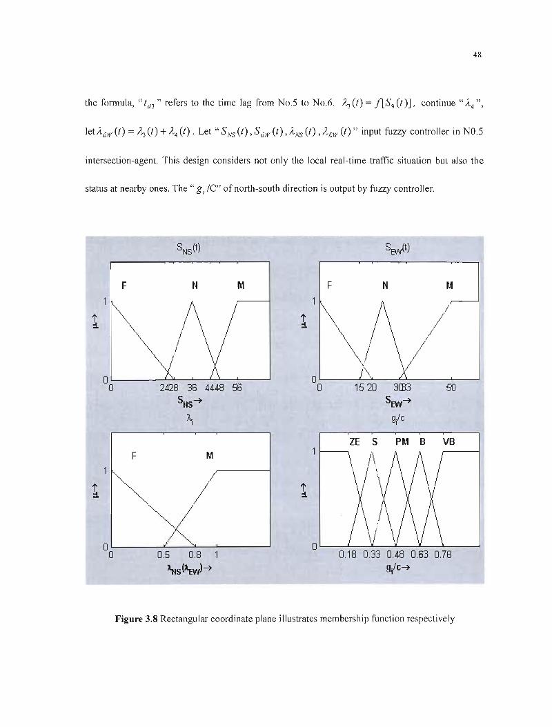
48
the formula, "td3 " refers to the time lag from No.S to No.6. A3 (t) =![S9(ï)] , continue" A4 ",
let AGW Ct) = A3 Ct) + A4 Ct) . Let" SNS Ct), SGW (t), ANS Ct) ,AEW Ct)" input fuzzy contro!ler in Nü.S
intersection-agent. This design considers not only the local real-time traffic situation but also the
status at nearby ones. The" g; le" of north-south direction is output by fuzzy control 1er.
SNS(t) SEVV(t)
F N M F N M
1 1
~ (\ 1 \\ 1\ /
\/ \ \'/
/ \0 0
0 2428 36 4448 56 0 1520 3œ3 50
sus~ SEW~
~ 9/C
S PM B VB F M
1 1 1
~ /Y""-.
,/ "-.0 0 0 0.5 0.8 1 0.18 0.33 0.48 0.63 0.78
~~S(~)~ g/c~
Figure 3.8 Rectangular coordinate plane illustrates membership function respectively

49
Figure 3.8 illustrates "SNS (t) , S /;w (t) , ANS (t) , Af.jW (t) and gi IC" membership function
respectively, we simplify the fuzzy variable and divide the quantity of vehicles into F (few), N
(normal) and M (many); divide the" g, IC" into ZE(zero extended), S(small), PM(positive
medium), B(big) and VB(very Big), discourse Il: U ~ [0,1] .
3.6.3 Simulation
We select the sample model to simulate just to testify the method's effect. Waiting vehicles
pass through the intersection one by one when the red light of certain phase transforms into green.
Ta simulate the traffic flow at intersection, a vehicle flowing mode! is setup as follows:
- 9.4(x1 (t) - x(t»A =exp( 2)
v(t)
2a(t + r) =0.2(- -l)(Vlimil - v(t»
1+ A
v(t) = v(t - !:J.t) + a(t)!:J.t
x(t) =x(t - !:J.t) + v(t - !:J.t)!:J.t + -1
a(t)!:J.t 2
2
In the formula, the" a(t), v(t) and x(t)" refer to acceleration, speed and displacement respectively.
" xI (t) " refers to displacement of the previous vehicle and" V 1irn il "refers to the maximum speed.
Table 3.3 is the comparison between the data calculated from vehicles flowing model and the data
abtained from observation. In view of those data, this model can quite effectively display the actual
vehicle condition. In the table, interval refers to the time difference of the two vehicles passing by
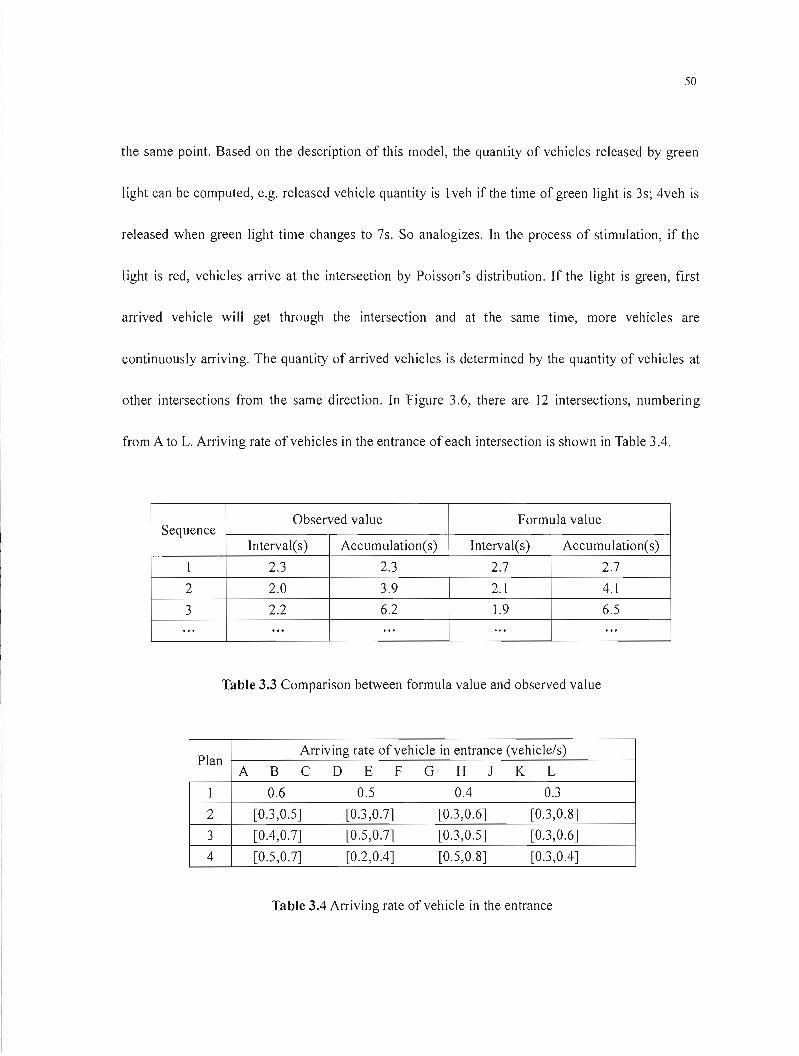
50
the sa me point. Based on the description of this model, the quantity of vehicles released by green
light can be computed, e.g. released vehicle quantity is 1veh if the time of green light is 3s; 4veh is
released when green light time changes to 7s. So analogizes. In the process of stimulation, if the
light is red, vehicles arrive at the intersection by Poisson's distribution. If the light is green, first
arrived vehicle will get through the intersection and at the same time, more vehicles are
continuously arriving. The quantity of arrived vehicles is determined by the quantity of vehicles at
other intersections from the same direction. In Figure 3.6, there are 12 intersections, numbering
from A to L. Arriving rate of vehicles in the entrance of each intersection is shown in Table 3.4.
Observed value Formula value Sequence
Interval(s) AccumuJation(s) 1nterval(s) Accumulation(s)
1 2.3 2.3 2.7 2.7
2 2.0 3.9 2.1 4.1
3 2.2 6.2 1.9 6.5 ... ... ... ... ...
Table 3.3 Comparison between formula value and observed value
Arriving rate ofvehicle in entrance (vehicle/s) Plan
A B C D E F G H J K L
1 0.6 0.5 0.4 0.3
2 [0.3,0.5] [0.3,0.7] [0.3,0.6] [0.3,0.8]
3 [0.4,0.7] [0.5,0.7] [0.3,0.5] [0.3,0.6]
4 [0.5,0.7] [0.2,0.4] [0.5,0.8] [0.3,0.4]
Table 3.4 Arriving rate of vehicle in the entrance

51
The actua! input values of Figure 3 to 6 are the random values within the range of the two numbers
in the bracket. Time unit is second.
It's supposed to have control parameters from predicted model of intersection-agent as follow:
Signal cycle: 90s. Switch loss between red and green lights in one cycle: 2.5s each, 5s total. The
minimum green light time: 15s. Average driving speed on road: 45km/h. A simulation period equals
60 signal cycles. Simulation tool is MATLAB. The simulation process is as follows.
Step 1: set up number of simulation cycle n= 1;
Step 2: set up intersection m= l, that is to begin with the computation from the first
intersection;
Step 3: Intersection "m" picks up the quantity ofwaiting vehicles ofeach phase; according to
the data in Table 3.2 together with the average speed on road works out a time lag used by vehicles
going from the intersection "m" to its neighboring intersections. Pick up the number of waiting
vehicles before the latest red Iight ends. (If one neighbor intersection happens to be an entrance-simulated
area, the number ofwaiting vehicles is replaced by multiplying the vehicle's arrivai rate in entrance
by half a signal cycle). According to the method discussed above, estimate the vehicle's arrivai rate
of each phase in intersection "m".
Step 4: According to the number of waiting vehicles and the arrivai rate in two phases, fuzzy
control 1er outputs" g i le" of a certain phase (here we use the North-south phase) of "nth" cycle at
"m" intersection, thus obtain the time for green light and red light in two phases.
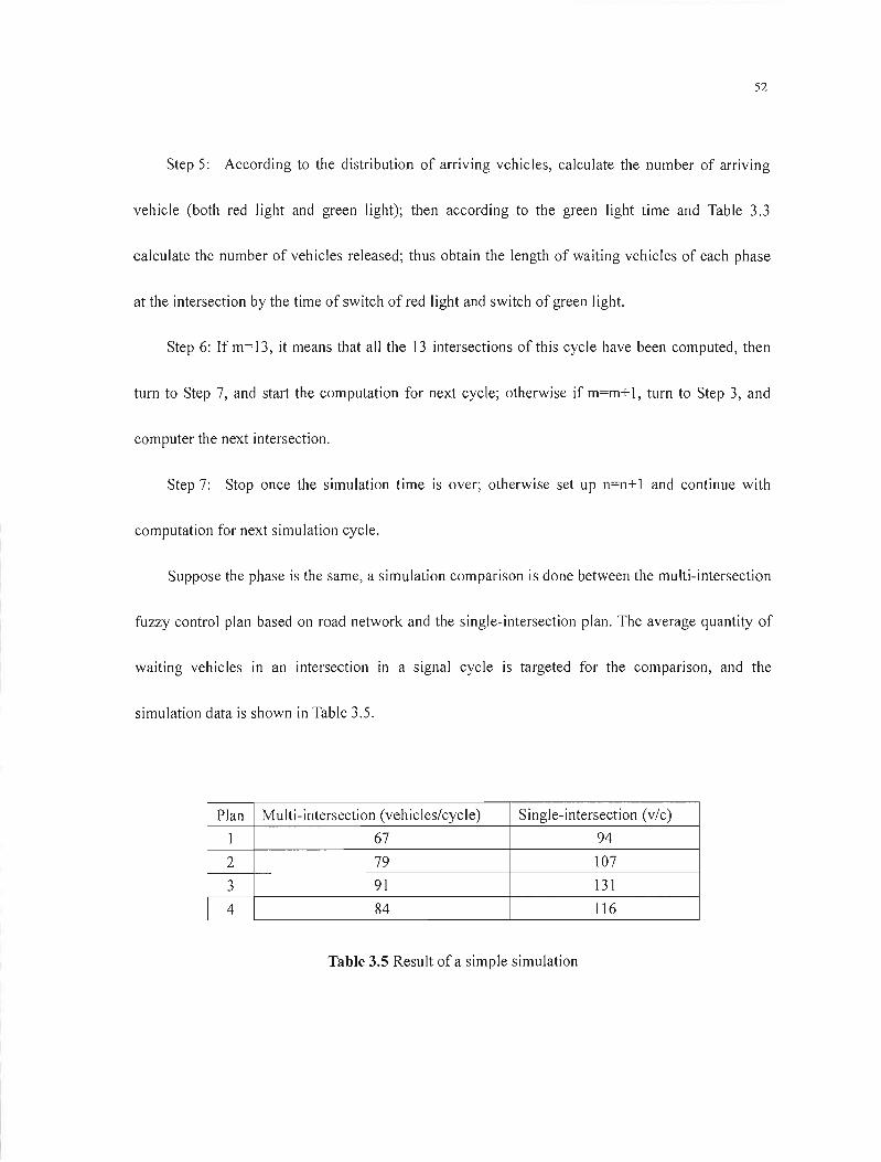
52
Step 5: According to the distribution of arriving vehicles, calculate the number of arriving
vehicle (both red light and green light); then according to the green light time and Table 3.3
calculate the number of vehicles released; thus obtain the length of waiting vehicles of each phase
at the intersection by the time of switch of red 1ight and switch of green 1ight.
Step 6: If m=13, it means that ail the 13 intersections of this cycle have been computed, then
turn to Step 7, and start the computation for next cycle; otherwise if m=m+ 1, turn to Step 3, and
computer the next intersection.
Step 7: Stop once the simulation time is over; otherwise set up n=n+ 1 and continue with
computation for next simulation cycle.
Suppose the phase is the same, a simulation comparison is done between the multi-intersection
fuzzy control plan based on road network and the single-intersection plan. The average quantity of
waiting vehicles in an intersection in a signal cycle is targeted for the comparison, and the
simulation data is shown in Table 3.5.
Plan Mu Iti-intersection (vehicles/cycle) Si ngle-intersection (vic)
1 67 94
2 79 107
3 91 131
4 84 116
Table 3.5 Result of a simple simulation
53
Analyzing the data, we draw such a conclusion that compared with the single-intersection fuzzy
control, the application of multi-intersection fuzzy control reduces the quantity of waiting vehicles
at each intersection and increases traffic transition though the traffic network and traffic flow
density remain the same.
3.7Autonomie Deeision-Making of Multi-Agent
In modern Chinese cities, there are four lanes or even more at the intersection. Each of
direction has its independent left-turning lane in a complicated intersection. As vehicles of right
turning are not influenced by the transformation of signais, we don 't consider them.
At a multiphase intersection, signal phases include the straight driving in North-South
direction, the straight driving in East-West direction, left-turning in N-S direction, left-turning in
E-W direction, left-tuming and straight driving in the South direction, left-turning and straight
driving in North direction, left-turning and straight driving in West direction, left-turning and
straight driving in East direction, left-turning in South and straight driving in East direction,
left-turning in North direction and straight driving in West direction, left-turning in West and
straight driving in South, left-turning in East and straight driving in North, ]2 phases in ail. Figure
3.9 shows them. For a multi-phase signal control system, it not only prevents a certain phase taking
too long a green light time but also avoids a premature transformation of signal. Each of
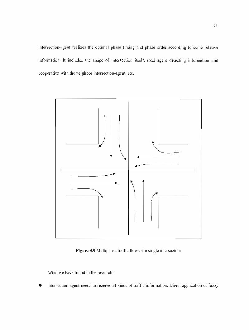
54
intersection-agent realizes the optimal phase timing and phase order according to sorne relative
information. It includes the shape of intersection itself, road agent detecting information and
cooperation with the neighbor intersection-agent, etc.
Jj ~ ..
...-.--.
~
~ ~
Figure 3.9 Multiphase traffic flows at a single intersection
What we have found in the research:
• Intersection-agent needs to receive ail kinds of traffic information. Direct application of fuzzy
55
control will cause too many variations. Fuzzy control rule is essential for fuzzy control;
moreover, the number of fuzzy control rules is the exponential function of the number of
control variables. Therefore, it is not easy to develop a conventional fuzzy controJler based on
rules. Even if we design such fuzzy controller, it cannot satisfY our real-time requirements
because of the oversized computation scale. Confronted with such a dilemma, we apply
decomposition-coordination method to fuzzy control. We introduce coordinate variable Ai to
coordinate with the green light time and div ide it into sorne corresponding subsets À i
according to the actual traffic conditions. The optimal Ai and Ài used by simulation help
us define them. This method can not only reduce iterative operation but also raise the
computed speed.
• We have studied sorne relative AI technologies. Fuzzy control can process the fuzzy
information effectively, but control rules are usually produced too rashly, when using rule table
to control, although computed speed is quick, it does not have self-Iearning ability. As what we
have mentioned above, NN happens to supplement fuzzy control with each other. As to GA, its
shOitcoming is bad real-time, but it does not fall into a partial optimization in the searching
process. Even if its fitness function is non-continuaI, non-ru 1er or noisy, it may probably find
the overall optimal solution, which fits for studying macroscopic rule of traffic system.
Moreover, using GA to optimize fuzzy control rules will avoid the subjective shortcoming by
"IF ... THEN " fuzzy control rule. ft can design optimally according to the required control
56
index.
• Multi-agent is a popular and effective technical process in the complicated intelligent control
system. Each intersection is an agent. Set up a regional agent to control those closely related
intersections based on the actual traffic conditions in cities. Individual intersection develops its
signal strategy based on local situations and cooperation with related intersections. As
different signais cause different impacts on the traffic flow at nearby intersections, sectional
optimization may lead to overall jam if it lacks unified control. Region agent acts as the final
arbitrator to control regional traffic. It dissolves traffic conflicts at the nearby area and reflects
traffic flux in real-time control strategy, to achieve real intelligent control.
Intersections in traffic network have different geometric shapes and traffic requirements. Some of
them only need a simple strategy to run weil, however some for instance on an artery need the
combination of multi strategies to make real-time adjustment. A major object of our simulation is to
choose the optimal signal control strategy respectively according to self-conditions and other
relative information until the overall traffic system runs optimally.
3.8Integrate Signal Control System with Other Transportation Systems
At present, urban traffic control can realize discrimination of ail kinds of vehicles by vehicle
positioning recognition system, which guarantees bus priority in future. In road network, public
57
transport servIce is prlor to all the others, which undertakes the main requirements of urban
transportation and its controlled effect directly influences the entire urban transportation conditions.
When a bus arrives at the area of detection, a detector embedded in road agent can recognize it and
inform the traffic signal control system to give it the priority in green light time. In the actual
operation, the range of signal control strategy caused by the priority must be limited. Obviously, we
note that time variation of signal phase because of priority is to be at certain loss in the time of
non-priority. We surely cannot accept signal switch frequently. We need to add new control rules to
our strategy.
In China, rapid rail transit is the main force for public transportation. But it is impossible to
rep lace the use of bus. How to coordinate signal control system with intell igent bus system wi Il be
one study emphasis.
3.9Summary
In this chapter, the author first made a brief analysis on the disadvantages of current traffic
control system. The author claims that we should make a design on the real-time intelligent traffic
control system by app!ying the multi-agent system to il.
Secondly, the author discusses the core of the agent's internaI working mechanism ----the
strategy for intelligent traffic-signal-controJ in details. The traditional strategy for traffic control
58
can 't meet the needs in real-time control, and so we are expected to find a solution to th is problem
by making use ofsomething in the artificial intelligence field. Each ofNN, GA, the Fuzzy Control
and the Expert System may have its strong points. In practice, we are supposed to use the above
four methods, and maybe their selective combination, so that we can actualize the optimal control
effects that we expect. For example, it is proved in practice that an experienced traffic policeman
can lead the traffic flow expertly, and so his experience can be shaped as an expert system.
Furthermore, it can be regarded as the basis for NN and Fuzzy Control research. GA is superior to
others in that it cannot easi Iy run into partial optimization in the process of search. Even if the
defined fitness function is not consecutive or regular, GA can get the overall optimal solution in a
major probability easily. Moreover, owing to its connatural parallelism, GA is more suitable for
harmonizing the signal control of various agents. At the same time, the author discusses something
about the combined usage of the GA and NN in this chapter. The advantage of NN is that it is
self-Iearning. However, the main problem with BP in NN is that it is slow for us to learn.
Fortunately, we can make improvements in BP algorithm and introduce the fuzzy theory into it so
that we can make an ANN-FC and two NN interactive learning to meet our needs for fast learning
and good convergence. As we have known, it can be inferred that fuzzy control is still the
mainstream in current traffic control research. Although it has a thirty-year-development history, it
is still worth further studying. Of course, we have made great effolts to solve this problem. And we
have made some simple simulations to test the rationality and actual effects ofthese technologies.
59
Finally, the author states that the most important thing is how to coordinate the intelligent
traffic signal control system with the public traffic intelligent control system. In China, the huge
population mainly depends on the public traffic in their daily life. Tt is one of the future prospects of
our further research.

60
CHAPTER4
INTELLIGENT TRAFFIC CONTROL SIMULATION RESEARCH
BASED ON AGENT
4.1 Brief Introduction ofTraffic Simulation
Traffie simulation teehnoJogy is a kind of traffie analysis teehnology. It is the important
application of computer analysis teehnology in traffie engineering. The traffie simulation system
ean show you the movement of ail vehieles on the traffie network intuitively by way of the
animation on the computer. Vou ean see elearly from the animation on whieh road the traffie is
eongested, and where the traffie is smooth. As a matter of faet, human being's visual observation is
a good eommentary means for a traffie engineering design. We ean roughly and visually know
whether a traffie engineering design is good or not by watehing animation on the computer. Owing
to the adoption of time-sean teehnology, eaeh vehiele's running course during eaeh seanning period
is perfeetly registered, so, we ean get sorne fixed quantity of estimating targets about the delay of
parking, the time for queuing, and the frequeney of collision on the road, etc. through some simple
statisties. As a result, the traffie simulation system is a visuaJ, eonvenient and flexible
traffie-analysis tool to the traffie engineers for testing and optimizing ail kinds of traffie and
61
roadway designs.
4.1.1 Applying Agent Teehnology to Do Traffie Simulation
Agent technology can provide useful guidance for promoting the structure of a traffic system.
The application of agent technology in traffic simulation can even embody the superiority of this
technology. Intelligent traffic control system is a complex and large one. It wi Il take us a lot of time
to carry through traffic layout and administration reasoning and investigating so as to prove whether
a design is reasonable or not. Ifwe put it on trial, it would cost too much. So a computer simulation
of how the traffic functions is a better solution to solve this problem. And it is not limited by time
and place. The simulation can even be repeated and adjllsted dynamically in the process of
simulation. In this case, the actual capacity of the simulation system to simulate the genuine system
is the very concern of common people. In traditional simulation, becallse of the limitation of
hardware and software, to perform such a highly dynamic and stochastic simulation in the traffic
system llsually can't achieve unsatisfactory results. Fortunately, with the development of computer
science, object-oriented technology has become the main purpose of software development, and
this does great contributions to the development of simulation, however, it has lots of disadvantages
in describing sorne mobile and intellective entities. The application of agent technology provides us
an ideal solution to this problem. Agent technology can be regarded as the development and
62
promotion of the object-oriented technology. It is the higher JeveJ of the object-oriented technology.
And it has provided us an optimal resolution to this problem. As a highly real-time discrete system,
the traffic system is the resu It of conjunctive effect of ail the traffic palticipators and traffic faci 1ities.
It is also the macroscopic exhibition of the microcosmic individuals. Any simulation using
mathematical methods can hardly achieve this outcome. However, as a non-model simulation, the
agent technology suits for solving this kind of problem. With the development of intelligent
transportation system, in order to understand the effect of ail kinds of control systems on real
transportation system such as UTFGS (Urban Traffic Flow Guidance System) and the USS
(Urgent Succor System) as well as the running rules of transpoltation better, we should not rely on
the traditional methods badly because they can not meet our needs. At present, many researchers are
interested in the application of agent technology in traffic simulation.
4.1.2 Realization ofAgent Technology
As a new method of software development, agent technique has inherited and developed from
the object-oriented technology. Agent technology not only has most of the characteristics of the
object-oriented one, but also is the enrichment and improvement of the objected-oriented
technology. Therefore, we can carry out the research and exploration of agent technology by using
the software tools coming from the present object-oriented technology. Furthermore, the developing
63
surroundings of the object-oriented software supply us with the capability of realizing the agent's
identities. Judging from the characteristics of the agent, autonomy is the essential property of it. At
the same time, autonomy is also the substantial difference that tells the agent from the ordinary
objects. The messages and the delivery of the messages are still the basis of its sociality. And it is
the further abstraction and promotion of the object-oriented message pattern. No matter how
profound it is in theory, the spiritual condition, namely, the spiritual quai ity of the agent can even be
regarded as one of the attributes of itself. So, the main difference between agent and general objects
lies in whether they have the active autonomy or not. But the process and the thread technique in
computer science are the technical basis for the actualization of autonomy. We use both the Java
Language, which is the neural and distributed architecture and multi-threads mechanism, and the
MATLAB Product Integration Setting, which is often applied in concept designing, arithmetic
exploring, modeling and simulating, as weil as real-time achieving, to simulate the alternation of
several different systems in practical environment. COMET (Concurrent Object Modeling and
architectural design Method) is adopted in the simulation system. One of the goals of COMET is to
construct several independent self-ruling subsystems based on the distributed application. And each
of these subsystems is a collocating component that can use the local database when needed. The
server subsystem can provide the database with a distributed access. In order to make a given
application be collocated with a1l of its subsystems being configuring to the independent physical
nodes, or be collocated with aIl or part of its subsystems being configuring to the same physical

64
node, it is required that we determine the mapping from the subsystem to the physical node in the
subsequent system collocating course, but not in the designing process. As a result, the
communication among the different tasks that are related to the different subsystems should be
demanded to use message communication. Only in this way can we establish a traffic environment
in accordance with the reality, and thus we can get a simulation environment, which is highly
collocating, concurrent and based on message communication.
4.1.3 The Characteristics ofTraffic Agent in Cooperation
In the traffic si mu lat ion surround ings for the agent, ail the transportation elements such as
vehicle (including the driver), section of a road, intersection, and traffic lights together with the
traffic-controll ing center are the intell igent agents. And ail of them are interacting and cooperating
with each other so as to achieve the simulation in the real traffic system jointly.
The simulation system can be looked upon as a Client/Server System, in which the client
(vehicle-agent) asks for traffic service from the relative server (road-agent), according to real-time
condition, while road-agent give vehicle-agent the feedback of optimum travel route and calculate
the number of vehicles that have different direction-turnings in the downstream intersection, then, it
(client) periodically send message ta relative intersection-agents (server). This is helpfuJ for
intersection-agent ta make fast and effective adjustment for control strategy in advance. After
65
receiving the order from the client, the intersection-agent corresponds with its neighboring agent
about the coming and going vehicles from ail directions. The region-agent coordinates in this
process, and the central-agent monitors the traffic statues of the whole urban area together with the
system-related coordination processing emergency case. After the vehicle-agent models are put into
the traffic network by concerned models the vehicles produce the model in simulation, they are
autonomous. Once they get into certain section on the road, they can communicate with the
correlative multi-agent systems. Its working mechanism is closely similar with applying GPS and
sensors in the real traffic condition.
The final goal of this system is to establish the multi-agent simulation system and the agent's
pertinent systematic functions such as General-Control Agent, Region Control Agent, Intersection
Agent, UTFGS-Urban Traffic Flow Guidance System, Information Delivering as weil as the
Running Modes of the Vehicle (including Free Driving, Following Driving, and Overtaking Driving)
and so on. At present, we place our emphasis on the simulation of the vehicles and the agent
intelligent traffic signal control. And in this way we can laya foundation for further simulation in
the future.
4.2Simulation Research on the Vehicle Agent
In the real urban traffic environment, the goal of all the traffic controlling methods is to serve
66
the vehicles better and more reasonably so as to meet the needs of people's going-out and the
economic and cultural development in the society. Hence, the simulation research of vehicles in the
traffic simulation environment is very important. Most former simulation models of vehicles are
based on mathematic model, not having taken into account of the fact that people control vehicles.
People's subjectivity has a strong effect on the running of individual vehicle, and thus influences
the traffic as a whole. Our hope is that we can grant the vehicle with intelligence in simulation so as
to make the simulation in the whole system closer to real traffic conditions. Thus, we can make
better controlling strategy by referring to the simulation effectively. According to the agent theory,
the vehicle in this system should have the capability of making decision and judgment and should
have its own knowledge. Moreover, the vehicle should be capable of adjusting the driving behavior
in accordance with the outside traffic conditions. In the following part, we will discuss the
simu lation in vehicle-agent.
4.2.1 The Structure Characteristic of the Vehic1e Agent
The vehicle-agent in this thesis refers to an abstract intelligent entity. It is designed to
re-embody the driver's behavior while driving. We use some computerized simulation methods to
do this simulation so that it can meet the needs in real traffic system research. The vehicle-agent has
the attributes of both the physical vehicle and the driver. It can not only get information from the
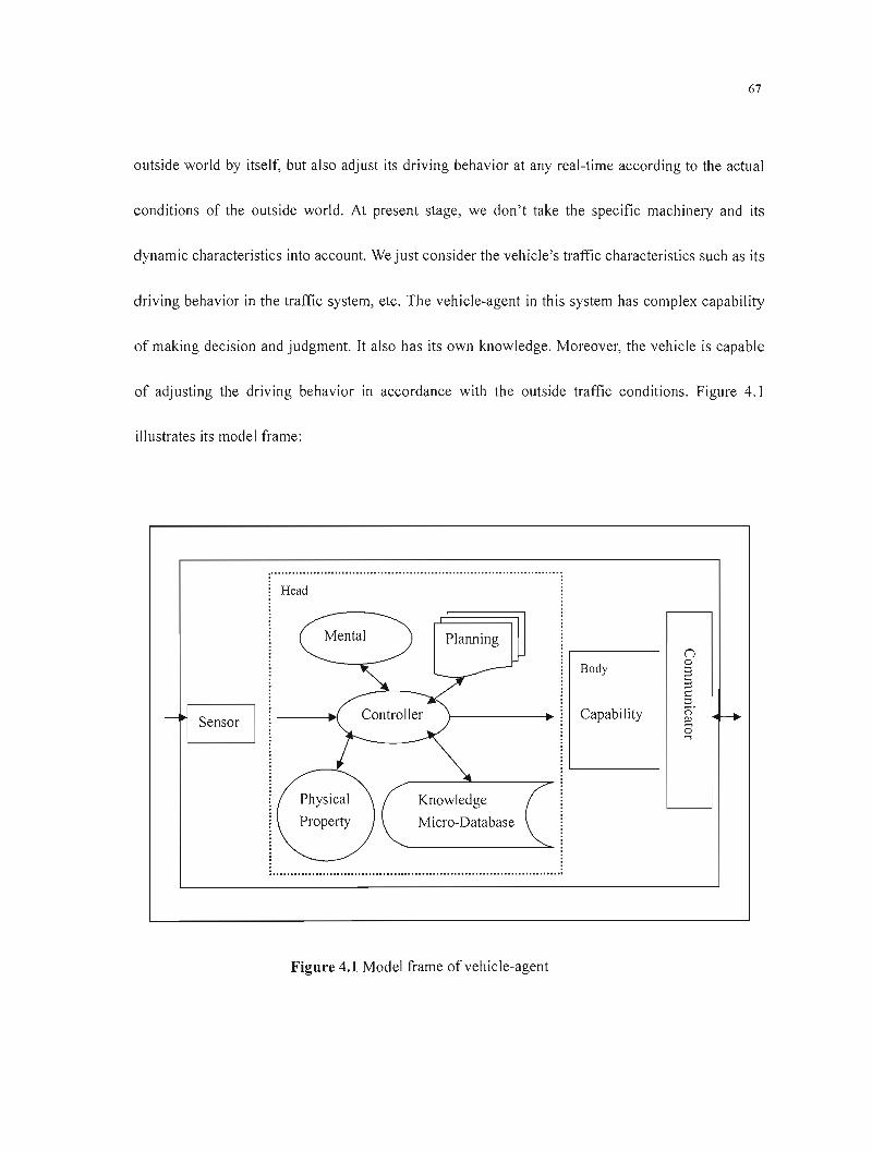
67
outside world by itself, but also adjust its driving behavior at any real-time according to the actual
conditions of the outside world. At present stage, we don't take the specific machinery and its
dynamic characteristics into account. We just consider the vehicle's traffic characteristics such as its
driving behavior in the traffic system, etc. The vehicle-agent in this system has complex capability
of making decision and judgment. It also has its own knowledge. Moreover, the vehicle is capable
of adjusting the driving behavior in accordance with the outside traffic conditions. Figure 4.1
illustrates its model frame:
Head
Control 1er
Mental Planning
Body
Capability
Knowledge
Micro-Database
Figure 4.1 Model frame ofvehicle-agent
68
In this model, the vehicle-agent exchanges information with the outside world through the
sensor and communicator in it. The sensor senses changes of the outside world, while the
communicator receives information from other agents or sends information to them. Planning
stands for the driving plan. Physical characteristic refers to the geometrical characteristic and the
performance index that are related to the vehicle. Mental factors refer to aIl the specialties
concerning with the driver, which mainly include the driver's characteristics and intention at present.
Knowledge Micro-Database is ail the knowledge that the vehicle-agent has, which includes driving
rules, controlling rules, and facts, etc. ControlJer is the running and controlling center of the agent,
which is responsible for the circulation of a11 the agent's functions. Capability denotes the
vehicle-agent's functions belonging to identity. Express it in details:
Physic attributes mainly include something about the vehicle's characteristics such as vehicle
trademark, position, speed, acceleration, direction, height, weight, width, top speed, economical
speed, destination and so forth.
Driver's attributes may include the type of the driver, sex of the driver, psychosis of the driver
and the fatigue degree of the driver, etc. which are ail connected with the driver.
Driving intention. ft refers to the urgency degree of the driver's driving task.
Driving plan. It is the running plan of the vehicle, which mainly refers to the present route of
the vehicle.
Capability: It refers to ail the driving functions the vehicle has, such as speedup, slowdown,
69
turn, overtaking, and parking, etc.
Control 1er: It is a strategy-controlling cell. The vehicle can make real-time driving strategy for
the next step according to its own characteristics and the traffic information received from the
surroundings by way of the controller.
Knowledge Micro-Database: It refers to ail the knowledge, facts and controlling rules tl1at the
vehicle-agent has. It is the basis for agent's decision-making. Knowledge Micro-Database includes
aIl kinds of data that belong to the vehicle itself as weil as those the vehicle get from the outside
world. Then the control 1er can make decisions and judgments according to aIl of the information.
Sensor: It is used to sense the stimu lation and changes from the outside environ ment. It
corresponds to various sensors in the real intelligent vehicles. But here it is only an invented sensor
designed with some functions.
Communicator: It is used to receive and send messages. It can interact with other agents.
4.2.2 Functions of the Vehicle Agent
4.2.2.1 The Functionary Distance of the Vehicle Agent
A field of vision is the farthest distance that a man can observe in driving. [n line with this trait, the
vehicle-agent also has an observing field that is called the vision of the vehicle-agent. The objects
beyond the vision are invisible to the vehicle-agent, and there are three types of distances with the
70
vision:
The farthest perceptive distance: "dL": The farthest distance that the vehicle can perceive is also
called the vision of the vehicle-agent. The vehicle cannot perceive the objects that are out of this
distance.
The controlled distance: "de": Within this distance, the vehicle can change its running state or
perform the overtaking or following according to how far away the vehicle or barrier are from it within
the vision as weil as their running conditions.
The smallest distance: "ds": Its aim is to prevent vehicles from crashing into another. It is the
function of the vehicle's speed. If the distance between vehicles is smaller than this, an emergency brake
is to be performed.
Generally speaking, the distance between vehicles (d) should be: ds < d <dl.' When the
distance is farther than the controlled distance, namely, d >de' the vehicle is believed to be in the free
travel.
4.2.2.2 Travel Planning
At present, we assume that the destination of the vehicle is fixed. So the vehicle should be capable
of adjusting its route momentarily in terms of the traveling environment. As a result, the vehicle-agent
should have a planner with il so as to control the route of the vehicle dynamically. Thus the vehicle can
71
regulate its traveling plan according to the variations of traffic conditions on different roads together
with its driving tasks.
4.2.2.3 The Driver's Characteristics
We use the word "driver" to represent the Driver Part in the vehicle-agent. This part includes
many factors such as characteristics of the driver, psychosis of the driver, sex, age and fatigue
degree of the driver, etc. Different characteristics of different drivers may have an effect on the
actual driving of the vehicle. For example, the young drivers are more intended to drive fast;
however the drivers' sensitivities become worse when they are tired and so forth. But now we only
consider what kind of effect the driver's characteristics have on his driving behavior. As to the other
factors, we plan to perfect them in later researches.
In order to make it convenient for our research, we divide the driver's characteristics into three
types: the rash one, the normal one and the cautious one. The rash driver tends to drive faster and
make drastic actions in acceleration and deceleration, while the cautious driver tends to be careful
drive slowly and make slight actions in acceleration and deceleration.
In order to reflect the changes in the drivers' types better, we define a variable" cD dnver ",
which can be used as a token in describing the drivers' characteristics. The value range of this
variab le is [-1,1]. And the characteristic operator " Adriver " is used to show the effects of the drivers'
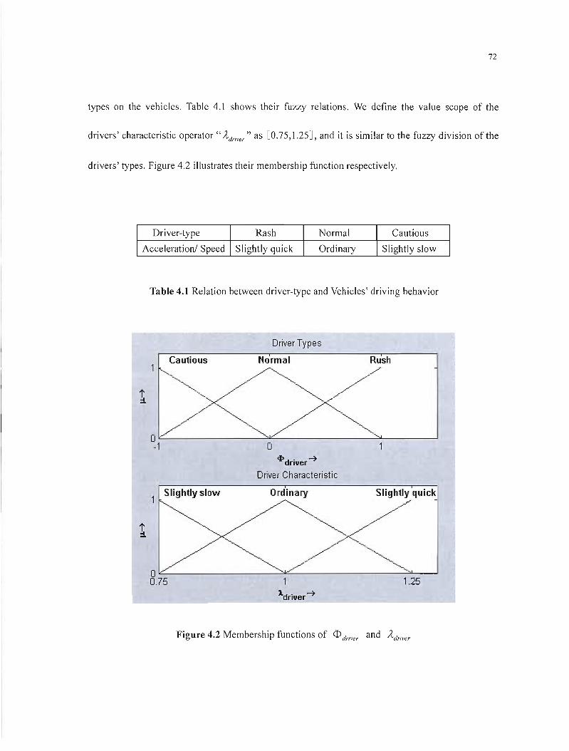
72
types on the vehicles. Table 4.1 shows their fuzzy relations. We define the value scope of the
drivers' characteristic operator "Â.driver" as [0.75,1.25], and it is similar to the fuzzy division of the
drivers' types. Figure 4.2 illustrates their membership function respectively.
Driver-type Rash Normal Cautious
Acceleration/ Speed Slightly quick Ordinary Slightly slow
Table 4.1 Relation between driver-type and Vehicles' driving behavior
Driver Types
Cautious Normal
1
O~---------='-----------=-------' -1 o
cJ>driver -7
Driver Characteristic
Slightly slow Ordinary Slightly quick /". ./'--", // "-~" ~/
""-..-/ '"-."- /1
~/~0' , 0.75 1.25
Figure 4.2 Membership functions of <D driver and Â.Jriver
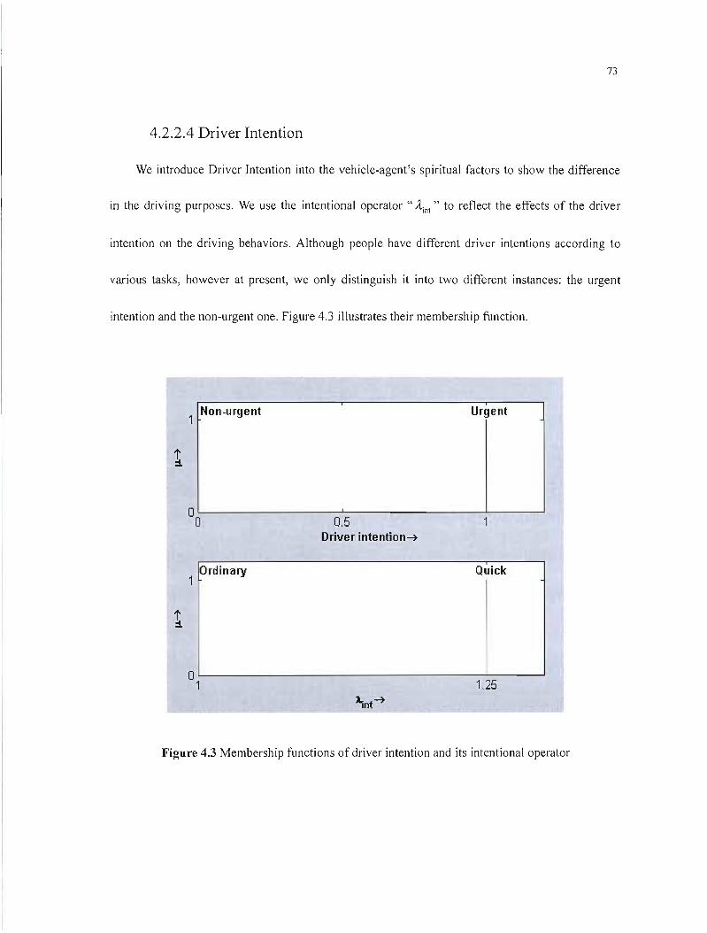
73
4.2.2.4 Driver Intention
We introduce Driver Intention into the vehicle-agent's spiritual factors to show the difference
in the driving purposes. We use the intentional operator " Â inl " to reflect the effects of the driver
intention on the driving behaviors. Although people have different driver intentions according to
various tasks, however at present, we only distinguish it into two different instances: the urgent
intention and the non-urgent one. Figure 4.3 illustrates their membership function.
1 Non-urgent Urgent
1
O'----------.l....---------~----l o 0.5 Driver intention~
Ordinary Quick1
1
O'-------------------~----' 1 1.25
Figure 4.3 Membership functions of driver intention and its intentional operator
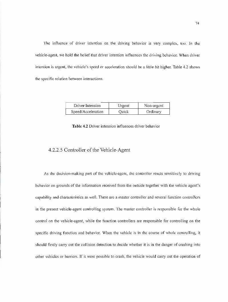
74
The influence of driver intention on the driving behavior is very complex, too. In the
vehicle-agent, we hold the belief that driver intention influences the driving behavior. When driver
intention is urgent, the vehicle's speed or acceleration should be a little bit higher. Table 4.2 shows
the specifie relation between interactions.
Driver Intension Urgent Non-urgent
Speed/Acceleration Quick Ordinary
Table 4.2 Driver intension influences driver behavior
4.2.2.5 Controller of the Vehicle-Agent
As the decision-making part of the vehicle-agent, the control 1er reacts sensitively to driving
behavior on grounds of the information received from the outside together with the vehicle agent's
capability and characteristics as weIl. There are a master control 1er and several function controllers
in the present vehicle-agent controlling system. The master controller is responsible for the whole
control on the vehicle-agent, while the function control1ers are responsible for controlling on the
specifie driving function and behavior. When the vehicle is in the course of whole controlling, it
should firstly carry out the collision detection to decide whether it is in the danger of crashing into
other vehicles or barriers. If it were possible to crash, the vehicle would carry out the operation of

75
avoiding crash at firsl. When the danger îs over, the vehicle will go on to perform other controlling
activities. Figure 4.4 illustrates il.
Among the vehicle's controllers, the master controller \S superior to the others. When
something unexpected happens, the master controller will stop the current controlling function and
switch to other more advanced controlling functions. After finishing the advanced one, the master
controller can switch back to pelform the former controlling functions on condition that the needs
are met. For example, if the vehicle wants to perform overtaking, but it suddenly finds that the
vehicle in the front accelerates or goes into the overtaking lane, the vehicle can return to its primary
lane and judge the proper condition for overtaking. When it is doable, the vehicle will carry out the
ovel1aking operation.
f" , " ~
: Master Control : : No ~ Sub-control
Exterior module
information : Collision Danger? examines
Yes
·1__R_e_fl_u_ge__
: ;
Figure 4.4 Vehicles master control implementation
76
The functions of each control 1er are as follows:
The master control 1er: It is responsible for the general control on the vehicle. It can make the
next driving operation according to the externat information and the vehicle's characteristics. Then
maneuver the different driving behavior controlling modules through different driving operations.
Free driving controller: It is in charge of controlling the driving behaviors when the vehicle is
in free traveling, or in other words, there is no vehicle in front of the controlled one or other
vehicles are far away from the controlled one.
Vehicle following contra/1er: It is responsible for adjusting the controlling process of its own
driving behavior by referring to the preceding vehicles' behaviors. In such a case, the distance
between the controlled vehicle and the preceding vehicles is within the retraining one, and it is
unsuitable for performing overtaking.
Overtake driving controller: It is responsible for controlling the vehicle's overtaking behaviors,
which includes changing lane and accelerating, regular driving on the overtaking lane, returning to
the former driveway and so on.
Intersection-driving control 1er: It is a special control1er that is responsible for control 1ing the
vehicle's driving behavior at the intersection.
Turning control 1er: It is in charge of control1ing the vehicle's turning behavior and this
function is usually transferred to the intersection-driving controller.
77
4.2.3 Controlling Process of the Vehicle Agent
The control of the vehicle-agent is a very complex process. In the traveling course, the
vehicle-agent must make continuai judgments and then determine its driving behavior according to its
position and other vehicles' status. In this process, the vehicle-agent should firstly judge its position
correctly so as to make proper decisions on its driving behaviors (For example, the driving operation on
the road and at the intersection should be different). The vehicle-agent should also determine its driving
behaviors at the intersection on grounds of its traveling route. Then the vehicle-agent should make
continuaI judgments on the preceding vehicle's driving behavior so as to make its specifie driving
operation. Figure 4.5 illustrates the main controlling flow:
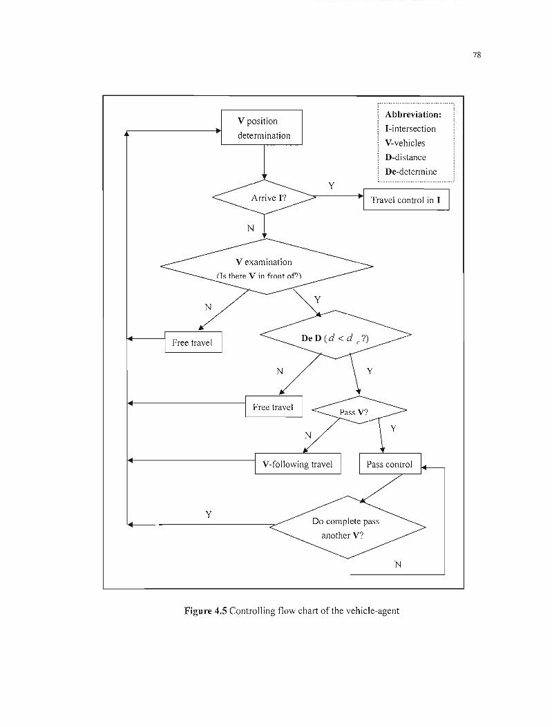
78
Abbreviation: V position
I-intersection determination
V-vehicles
D-distance
De-determine
y
Travel control in 1
N
N
y Do complete pass
another V?
N
Figure 4.5 Controlling flow chat1 of the vehicle-agent
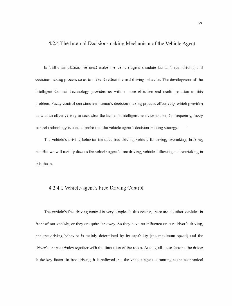
79
4.2.4 The InternaI Decision-making Mechanism of the Vehicle Agent
In traffic simulation, we must make the vehicle-agent simulate human's real driving and
decision-making process so as to make it reflect the real driving behavior. The development of the
Intelligent Control Technology provides us with a more effective and useful solution to this
problem. Fuzzy control can simulate human's decision-making process effectively, which provides
us with an effective way to seek after the human 's intelligent behavior course. Consequently, fuzzy
control technology is used to probe into the vehicle-agent's decision-making strategy.
The vehicle's driving behavior includes free driving, vehicle following, overtaking, braking,
etc. But we will mainly discuss the vehicle agent's free driving, vehicle following and overtaking in
th is thesis.
4.2.4.1 Vehicle-agent's Free Driving Control
The vehicle's free driving control is very simple. In this course, there are no other vehicles in
front of our vehicle, or they are quite far away. So they have no influence on our driver's driving,
and the driving behavior is mainly determined by its capability (the maximum speed) and the
driver's characteristics together with the limitation of the roads. Among aU these factors, the driver
is the key factor. In free driving, it is believed that the vehicle-agent is running at the economical
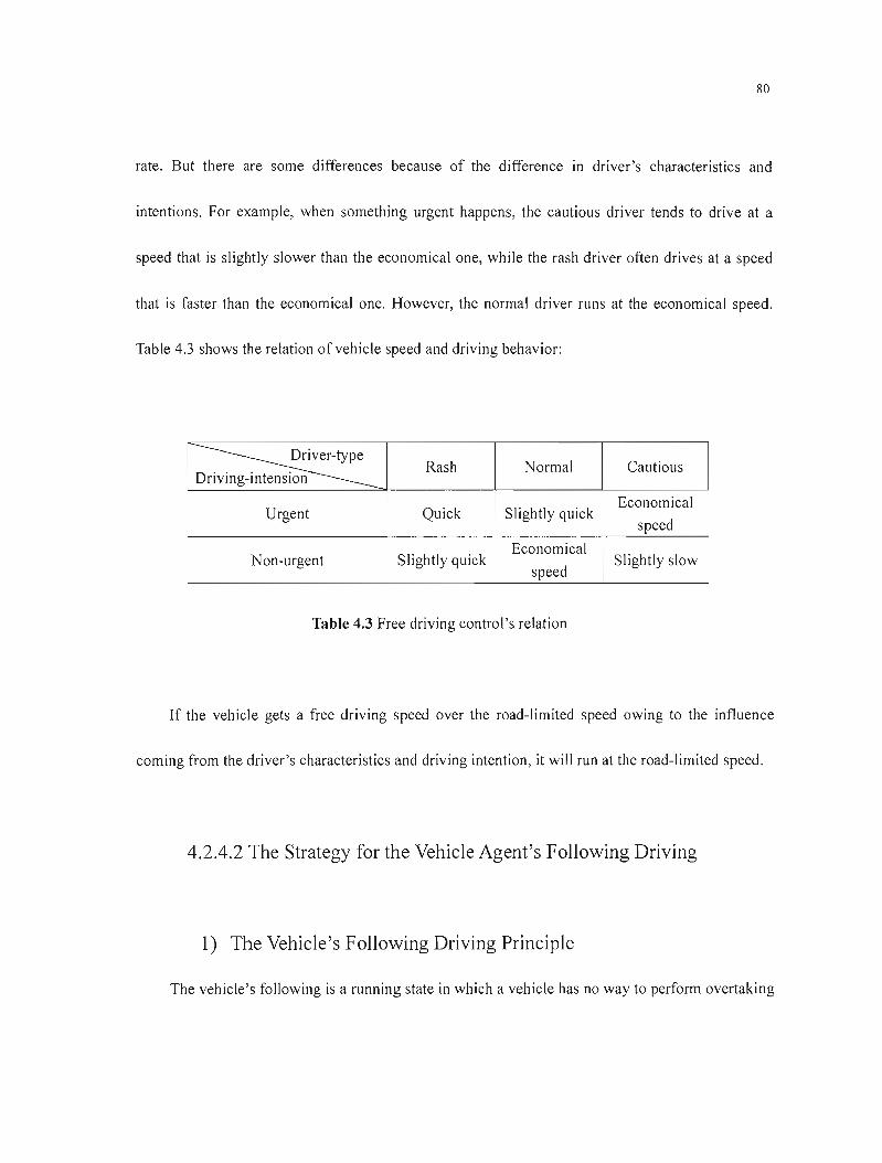
80
rate. But there are sorne differences because of the difference in driver's characteristics and
intentions. For example, when something urgent happens, the cautious driver tends to drive at a
speed that is slightly slower than the economical one, while the rash driver often drives at a speed
that is faster than the economical one. However, the normal driver runs at the economical speed.
Table 4.3 shows the relation of vehicle speed and driving behavior:
Driving-intension Rash Normal Cautious
Urgent Quick Slightly quick Economical
speed
Non-urgent Slightly quick Economical
speed Slightly slow
Table 4.3 Free driving control's relation
If the vehicle gets a free driving speed over the road-limited speed owing to the influence
coming from the driver's characteristics and driving intention, it will run at the road-limited speed.
4.2.4.2 The Strategy for the Vehicle Agent's Following Driving
1) The Vehicle's Following Driving Principle
The vehicle's following is a running state in which a vehicle has no way to perform overtaking

81
operation but to follow the front one. In this case, the drivers are trying their best to keep their
vehicles within the safe distance in order to avoid car crash. For this purpose, drivers have to adopt
corresponding running scheme according to the front vehicles' running state. As a result, the back
vehicle's running speed and the distance between the back vehicJe and the front one is limited by
the front one and the back vehicle is in a non-free running state. Furthermore, the drivers' inborn
reactions are different, so the front vehicle's and the back one's actions are not synchronous. The
back vehicle driver needs a course to react to the changes of the front vehicle's speeding-lip and
slowing-down, etc. If the front vehicle has sorne changes in action at the "t" moment, the back one
can only react to it at the "(t +T)" moment thlls causes the lag.
If it is supposed that the front vehicle " n " is in the position" x n (t) " at the time of" t ", and
the back vehicle " n+1 " is in the position" xn+1(t)" at the time of" t ", the vehicle following
driving model can be inferred from the above, namely:
1 4+1 (t + T) =-[.x%(t) - .x%+1 (t)] (1)
T
And this is the vehicle's linearity tracking mode!. Unfortunately, this model hasn't shown the
distance-relation between the two vehicles. This obviously collides with the truth. The modified
vehicle following model should be:
4+1 (t + T) =a [.x%+1 (t + T)r L [.x%(t) - .x%+1 (t)] (2) [x n (t) - xn +\ Ct)]
In this model, "a = ~" is the measllrement of sensitivity, " m, L "are constants. We can also T
say that the vehicle's acceleration and the two vehicles' margin in speed are in direct proportion,
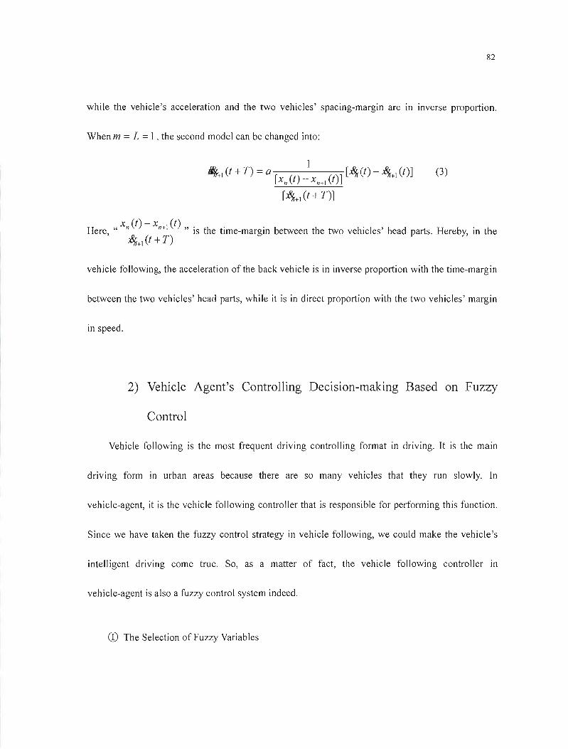
82
while the vehicle's acceleration and the two vehicles' spacing-margin are in inverse proportion.
When m =L =1, the second model can be changed into:
1 4+1 (t +T) = a [X (t) _ X + (t)] [-,%(t) - -'%+1 (t)] (3)
n n 1
[-'%+1 (t +T)]
Here, "xn (t) - xn+1 (1) " is the time-margin between the two vehicles' head parts. Hereby, in the -'%+1 (t +T)
vehicle following, the acceleration ofthe back vehicle is in inverse proportion with the time-margin
between the two vehicles' head parts, while it is in direct proportion with the two vehicles' margin
in speed.
2) Vehicle Agent's Controlling Decision-making Based on Fuzzy
Control
Vehicle following is the most frequent driving controlling format in driving. It is the main
driving form in urban areas because there are so many vehicles that they run slowly. In
vehicle-agent, it is the vehicle following controller that is responsible for performing this function.
Since we have taken the fuzzy control strategy in vehicle following, we could make the vehicle's
intelligent driving come true. So, as a matter of fact, the vehicle following controller in
vehicle-agent is also a fuzzy control system indeed.
CD The Selection of Fuzzy Variables
83
As we are carrying out the microcosmic simulation in traffic system, we assume that the
vehicle is an ideal vehic1e; the road is also an ideal straight road, and the vehicle doesn't have
any heeling-over and going-on-the-rampage in running. We also presume that the vehicle runs
in a fixed direction in the following driving so as to predigest the vehicle's controlling behavior
in movement.
According to the analysis of the vehicle's driving behavior in vehicle following, we know
that it is the front vehicle's driving behavior that a mainly influence the back one's driving
behavior. And the key factor that has an effect on the drivers is the speed-margin and
spacing-margin between the head parts of the two vehicles. The driver can't get the exact
speed-margin of the two vehicles. He can only judge the changes in the speed-margin on
grounds of the changes in the spacing-margin. At the same time, the vehicle agent's driving
behavior is also affected by some other factors such as the driver's characteristics and
intentions, etc. Hence, in fuzzy control of the vehicle agent's vehicle following, we define
input value as "dl "(the time-margin between the head parts of the two vehicles) and changes
in" /j,d" (the spacing-margin between the two vehicles); while we define output value as" a"
(the vehic!e's acceleration, and it is minus when braking.). This decision-making process IS
affected synchronously by the driver's characteristics and intention. Figure 4.6 illustrates it:
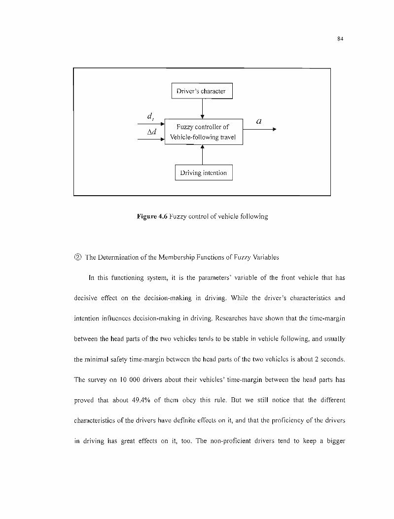
84
1 1Driver's character
dt a Fuzzy controller of
/)"d Vehicle-following travel
1 1Driving intention
Figure 4.6 Fuzzy control ofvehicle following
@ The Determination of the Membership Functions of Fuzzy Variables
In this functioning system, it is the parameters' variable of the front vehicle that has
decisive effect on the decision-making in driving. While the driver's characteristics and
intention influences decision-making in driving. Researches have shown that the time-margin
between the head parts of the two vehicles tends to be stable in vehicle following, and usually
the minimal safety time-margin between the head parts of the two vehicles is about 2 seconds.
The survey on 10 000 drivers about their vehicles' time-margin between the head parts has
proved that about 49.4% of them obey this rule. But we still notice that the different
characteristics of the drivers have definite effects on it, and that the proficiency of the drivers
in driving has great effects on it, too. The non-proficient drivers tend to keep a bigger

85
head-parts time-margin with other vehicles in order to make up for their insufficiency in
operating. Meanwhile sorne outside conditions such as road's conditions and weather
conditions also influence the vehicles' head-parts time-margin. For instance, the vehicles'
head-parts time-margin tends to be a little bigger in a rainy or foggy day.
We define the fuzzy language variables of time-margin as five different instances in this
thesis: the big one, the biggish one, the moderate one, the small one and the smaller one. We
only take two factors---the driver's characteristics and intention into account, neglecting other
outside factors provisionally. We are to find out in which way these two factors affect the
driving behavior. We have talked about the effects of the drivers' characteristics and intention
on the speed or acceleration in driving in the previous part. But in vehicle following, we
believe that the drivers' different types influence the vehicle-agent mainly by influencing their
choices on the vehicles' head-parts time-margin. We can easily know that the rash drivers tend
to choose a lesser head-parts time-margin in driving, whiJe the cautious drivers tend to keep a
biggish one in driving. Therefore, based on the analysis of the three different types of drivers'
characteristics, we can draw a conclusion that the head-part time-margin of different types of
drivers in vehicle foJlowing differ from each other greatly. The normal drivers keep a nonnal
head-part time-margin division in driving, whose value scope is (l, 1.5, 2, 2.5, 3); the rash
drivers keep a lesser head-part time-margin, whose value scope is (0.5, J, ) .5,2,2.5); while the
cautious drivers keep a biggish one, whose value scope is (l.5, 2, 2.5, 3, 3.5). Figure 4.7

86
illustrates their fuzzy relationship respectively, and we define them as the big one, the
moderate one and the small one.
Rash
Small Le Bi
~'\. X501 0.5
/ '\"0 0 0.5 1 1.5 2 2.5 3 3.5
l\(s)--+
Normal
1
10.5
0 0 0.5 2 2.5 3.5 4
l\(s)--+
Cautious
10.5
0.5 1.5 2 2.5 3 3.5 4 4.5 l\(s)--+
Figure 4.7 Fuzzy membership function dl (unit: Sec) of different driver-types
Meanwhile different driving intentions of different drivers may also affect the choice of

87
head-part time-margin. The driver with an urgent task may also keep a lesser head-parts
time-margin. But because of the limitations coming from human 's reacting ability, the vehicles'
head-part time-margin mustn't be too short. As a result, in our present research, we believe that
even if the rash drivers were in emergency, their vehicles' head-part time-margin would not
become shorter ulteriorly. Table 4.4 illustrates its detailed interactive relation.
Driving-intension Rash Normal Cautious
Urgent Small Small Moderate
Non-urgent Small Moderate Big
Table 4.4 The relationship of driving factors and head-part time-margin
Fuzzy language variables for spacing-margin changes and acceleration are {NB (negative big),
NM (negative moderate), NS (negative small), ZE (zero extended), PS (positive small), PM
(positive moderate) and PB (positive big)}. Their value scopes are (-3, -2, -1,0, 1,2,3), and Figure
4.8 illustrates their membership functions.
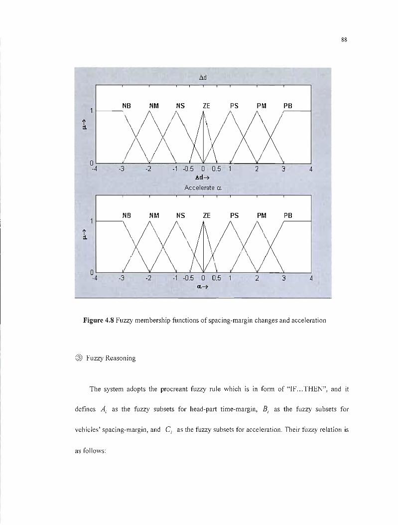
88
Lid
NB NM PB
1,\)(/\
\
1\ 0 -4 -3 -2 -1 -0.5 0 0.5 2 3 4
Ad--7
Accelerate CL
PS PM PB
1
1
0' -4 -3 -2 -1 -0.5 0 0.5
V'/ t 1 .
2 \
3 4 0..--7
Figure 4.8 Fuzzy membership functions of spacing-margin changes and acceleration
® Fuzzy Reasoning
The system adopts the procreant fuzzy ru le which is in form of "IF... THEN", and it
defines Ai as the fuzzy subsets for head-part time-margin, Bi as the fuzzy subsets for
vehicles' spacing-margin, and Ci as the fuzzy subsets for acceleration. Their fuzzy relation is
as follows:
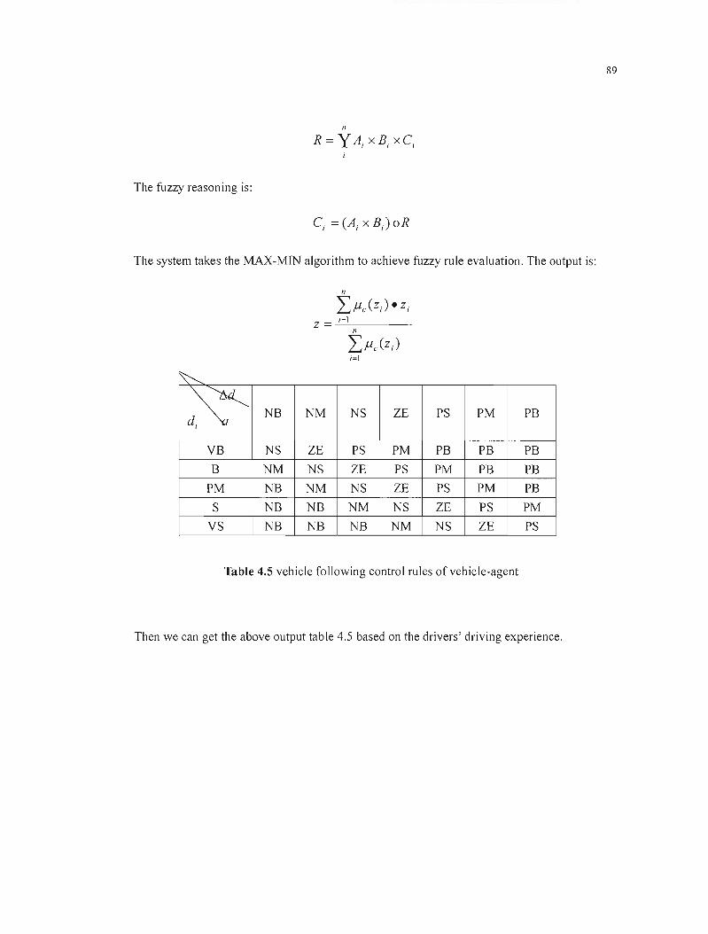
89
n
R =y Ai X B, X C,
The fuzzy reasoning is:
The system takes the MAX-MIN algorithm to achieve fuzzy rule evaluation. The output is:
n
L>.LC(Zi)· Zi
Z = --'--i=--'-I _
~
~ NB NM NS lE PS PM PB
VB NS lE PS PM PB PB PB B NM NS lE PS PM PB PB
PM NB NM NS lE PS PM PB S NB NB NM NS lE PS PM
VS NB NB NB NM NS lE PS
Table 4.5 vehicle following control rules of vehicle-agent
Then we can get the above output table 4.5 based on the drivers' driving experience.
90
4.2.4.3 Controlling Strategy for Vehicle-Agent's Overtaking
1) The Principle for Overtaking
The vehicle cannot only perform vehicle following but also carry out overtaking operation
when being permitted in running. Drivers often take overtaking operations. Tt is different from
vehicle following driving. Overtaking is not only concerned with the driving behaviors of the
overtaken vehicles, but also related to the driving behaviors of the vehicles on the opposite route
(considering some relatively narrow roads in Chinese cities). Hereby, overtaking is a little bit
complex.
When performing overtaking, the vehicle is to switch to the left lane or the opposite lane. So,
there should be a safety distance that is called "S" for this performance. This distance is also
named "full distance for overtaking", which refers to the safety overtaking distance that guarantee
the willing overtaking vehicle is able to accelerate and overtake the front one. Overtaking is a
complex process, which involves many stochastic factors. For example, the vehicle-type and the
road's condition, etc. influence overtaking. And the distance suitabJe for overtaking is closely
related to the speed of the overtaking vehicle, the overtaken vehicle and the opposite-route vehicle
as weil.
If the back vehicle wants to perform overtaking, it must speed-up at first to run faster than the
front one and change its running lane. When the overtaking is over, having the safety distance that

91
permits it going back to its normal running lane without influencing the overtaken vehic1e, it will
switch back to its original lane, then the overtaking is over. Owing to the existence of the
complexity and uncertain factors in overtaking process, there is no strict definition on the specifie
steps in the whole overtaking course; however, we divide the whole overtaking process into three
phases in this thesis:
CD Accelerating and Changing Lane
We think that the acceleration speed of the overtaking vehicle keeps the same while the
overtaking vehicle begins to accelerate and change into the overtaking lane or the opposite one.
And in this period the overtaking vehicle has to run a distance, which is called "dl ". And we
define "So" as the distance between the overtaking vehicle and the overtaken one before the
overtaking is performed. We assume that "N 1" is the overtaking vehicle, "VI" is its initial
velocity, its acceleration is "a ", the time for accelerating is "fi ", and" v2 " is the speed at
which the vehicle runs when the acceJeration is over. We can get a formula from the above
assumptions:
® Uniform Speed Running on the Overtaking Lane or the Opposite One
When the acceleration is over, the vehicle will go into the overtaking lane or the opposite
one and runs at the uniform speed. We assume that during this period the overtaking vehicle
92
has run a distance, which is assumed to be "d2 ". And we assume that "S," is the safety
distance between the overtaking vehicle and the overtaken one in which the overtaking vehicle
" NI" has exceeded the overtaken one" N " but hasn 't switched back to its former lane yet.
It is assumed that the time needed for finishing this distance is "/ 2 ", and then we can get the
following formula:
® Returning to the Original Lane
The overtaking vehicle will retum to its original lane when the overtaking is over. The
running distance during this time is "d3 ". We presume that the overtaking vehicle "N 1" keeps
the same speed "v2 ", and the running time is "1 3 ". Then we can get:
We assume that there is an opposite vehicle "N2" runs at the uniform speed on the opposite
lane when the vehicle "N 1" is performing the overtaking operation, and the opposite one IS
running at the speed of" v3 ", we presume" d4 ":
And we make a presumption again that "ds" is the distance between the overtaking vehicle
and the opposite one when the overtaking is over. Thus we can get the safety distance for
overtaking.
S =dl + d 2 + d3 + d4 + ds
93
If the distance between vehicle " NI" and the first opposite vehicle " N2 " is longer than "s ",
we say that vehicle " NI" can overtake vehicle " N" safely; otherwise, vehicle " NI" can't
perform overtaking operation. It has to do the following driving behind vehicle "N". During
this period, vehicle "NI" will make real-time judgments on the distance between itself and the
front vehicle as weIl as the vehicles on the opposite lane, then decide whether to overtake or
not by considering ail the information with its driving intention.
2) The vehicle agent's overtaking control
According ta the above analysis on the overtaking process, we can conclude that the overtaking
process includes the following steps:
CD Making judgments on the possibility of overtaking. The vehicle will make judgments to
perform overtaking or not according to the concerned data of the vehicle. If it is allowed ta perform
overtaking, it will carry out this function without any delay. But if it is impossible, the vehicle wi Il
maintain the vehicle following.
@ Accelerating and changing lane.
® Running on the overtaking lane.
@ Making estimation ta see whether it is able ta return ta its normal lane or not. If the distance
between itself and the object vehicle is longer than the safety distance, it will prepare ta switch
back ta its normal lane.
® Returning ta the normallane.

94
We simply analyzed the vehicle's overtaking process in the previous part, which is determined by
the outside factors. But in the vehicle-agent, we also take the drivers' characteristics and intentions into
account, and these two factors will also affect the vehicle-agent's overtaking behavior. In this case,
whether to overtake or not is decided by the driver, who makes judgments according to the outside and
internaI factors.
We classify the conditions for the vehicle's overtaking as the following four types according to the
vehicle's overtaking distance: Good, Generic, Bad and Unsuitable. Good condition means the
overtaking distance is big, and the vehicle can easily finish the overtaking operation with lesser
acceleration. Generic condition means the overtaking distance is mezzo and it needs a moderate
acceleration to accomplish overtaking. Bad condition means the overtaking distance is short and it
needs a biggish acceleration to finish overtaking constrainedly. Unsuitable condition means overtaking
is forbidden. We can get the controlJing relation between them based on the analysis of the conditions
for overtaking and the vehicle-agent's characteristics. See Table 4.6.
Driving-intention Urgent No-urgent
~:P-Condition Rash Normal Cautious Rash Normal Cautious
Good P P P P P P
Generic P P P P P 1
Bad P 1 NP 1 NP NP
P: Pass the other vehicle; NP: No passing permitted; l: Indefinite
Table 4.6 Overtaking decision-making control of vehicle-agent
As to the uncertain conditions, it will be up to the computer to determine randomly in simulation.
95
4.3Road Agent Study
To realize ITS, an intelligent road network is necessary. To lighten the burden of intersection
signal control, it is necessary to make vehicles driving on roads communicate with intelligent
monitor facilities equipped on urban roads at real-time. Obviously, each road is an agent, which
makes up a multi-agent system. We'lI do a research on road agent from the following aspects:
• Intelligent traffic guidance: when vehicle-agent drives onto a road, corresponding road agent
should communicate with vehicle-agent at real-time according to traffic conditions at that time,
meanwhile advise it to follow the optimal driving route, furthermore, guide classifiably
accord ing to the veh icle's characteristics.
• Real-time traffic control: an important factor to achieve real-time control is to reduce the
system's complexity. Ali vehicles communicating with intersection-agent will greatly reduce
the practicality and economy of the system; meanwhile inter-communication among vehicle
agents will make vehicles fuzzy in so much information. So road agent is the bridge between
intersection-agent and vehicle-agent. Not ail the vehicles driving onto certain road should leave.
Sorne of them may stop. Road agent should watch and collect necessary vehicle information
(i.e. total number of vehicles to reach certain intersection and the number of vehicles to be
divided into different directions, etc.), then feedback intersection-agent in time to control
vehicles in advance using signal strategy; vice verse, road agent "suggests" vehicles on speed,
96
driving route, etc. according to relative intersection-agent control information and its physical
characteristics.
• Accident inspection: when traffic accidents happen on certain road, inform relative intersection
signal control agent not to let vehicles enter temporarily and meanwhile, guide better driving
routes by multi-agent system.
We think that intelligent road network is the basis of real-time traffic control. At present we
focus on intersection-signal control as the vehicle-agent indicated above. Simulation research on
road network agent plays an important role in the whole real-time control system. It gets ready for
further realization.
4.4Summary
This chapter mainly inducts what traffic simulation is and something about the tendency of
using agent technology to do traffic simulation. In order to ref1ect the developing tendency of the
intelligent urban traffic in the future, we are expected to make ail the concerned models in the
simulation system turn into agents. We believe that the vehicle-agent is the keyword to the whole
traffic simulation system. Therefore, we discussed the operating strategies of the vehicle-agent in
running in detail based on the assumption that the agent composes the mechanism of the system.
We apply fuzzy theory to the vehicle's strategy making process on the presumption that people
97
often make fuzzy controis in making strategy and judgment so that we can make the vehicle-agent
more effective in making different strategies and judgments. According to the different operating
types in practice, the chapter gives us a detailed description of the vehicle agent's specifie
decision-making methods in free driving, following driving and overtaking. Then we discussed in
detail the influence of the driver's characteristics and intentions on operation. We introduce road
network multi-agent system in the end. It offers us a valuable reference in promoting the
authenticity and variety oftraffic simulation.

98
CHAPTER 5
TO ACHIEVE SIMULATION USING OBJECT-ORIENTED
TECHNOLOGY
The agent teehnology provides us with a more advaneed means to develop software and it is
more benefieial to solve the eomplex systematie problems. However, the present research based on
the agent software-developing environment is comparatively slow versus the development of agent
theory. The simulation in this system uses the object-oriented technology to develop a distributed
architecture based on agent so as to make the agent's methods come true.
5.1 The Structural Design of the MA-URTC Simulation System
The basic functioning theory and aims of the traffie simulation system are: under a given
traffic eircumstance, make the vehicle go into the traffic network one by one in its producing area
aecording to certain random distribution. Then use time-scanning method to scan each of the
vehicles' running condition in each seanning period till it arrives at its destination or disappears in
terminal from the traffie network. In this proeess, we ean seek out a classie or optimum solution to
solve traffie problem by comparing various traffie eontrolling strategies to serve the real-time traffie
99
control better in the urban.
The single-computer simulation environment of the system is going to be changed. In order to
re-embody the real traffic controlling condition exactly, the system takes the network as simulation
surroundings to realize distributed simulation. It has better scalability, versatility and reusability, etc.
More importantly, it can fast dispose the actual traffic control system. We can set several computers
as Intersection-agents and then carry out the controlled signal simulation according to the
simu lation on its relative traffic network and traffic flows. And this intersection-agent can
communicate with the neighboring intersection-agent conforming to the actual parameters. The
Region-Agent computer controls and cooperates with the communication. Then we can simulate
the watching-on, which is the responsibility of the General-Agent computer, over the traffic
network. For example, we can set many a computer as the same simulating environment except that
they are different in signal controlling strategy so as to find out the most optimum resolution by
comparing simulation in the same period. In former simulation, the vehicle always appears and
disappears at the edge of the traffic network, and this is not the case in reality. One of the
advantages of distributed simulation is that a single computer can make the vehicle appear or
disappear within the area controlled by it. Meanwhile it can take in other vehicles that come from
other areas. It can even let these vehicles "drive out", "disappear" or "stop and wait for driving
again". The vehicle's coming-up and fading-away on the roads are the main factors which influence
the traffic flows in urban area. The whole design in structure conforms to the real traffic conditions
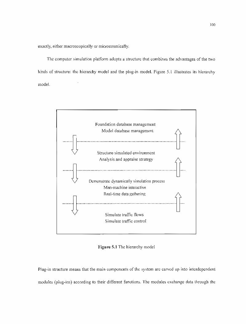
100
exactly, either macroscopically or microcosmically.
The computer simulation platform adopts a structure that combines the advantages of the two
kinds of structure: the hierarchy model and the plug-in mode\. Figure 5.1 illustrates its hierarchy
model.
Foundation database management
Model database management 0 ·······H·············································· .. u···········U·
U Structure simulated environment
·····n····:~:~::::s:::::·;::;:~:=::~:·::~r~~~:s······U. Man-machine interactive
········D·················R::~;,~~.::~~::;~:~....... u···D·· Simulate traffic control
Figure 5.1 The hierarchy model
Plug-in structure means that the main components of the system are carved up into interdependent
modules (plug-ins) according to their different functions. The modules exchange data through the

101
database then actualize the function conjunction. To achieve the plug-in structure, we need sorne
highly eligible interface modes. Figure 5.2 shows plug-in structure drawing.
Simulate
/ Dynamical
Control traffic flows display
strategy ~ input/output
...... -;;1"'" ~.- Man-machine Database
interactive /f -----\
Analysis VV
and appraise Real-time1\
Simulate traffic data gathering
signal control
Figure 5.2 The plug-in model
MA-URTC aims to aehieve ail the systematie Multi-agent Simulation environments that are
related to the traffie. But at present, we only perform the intelligent simulation designs on traffic
signal eontrolling agent, the vehicle-agent and the road agent. Based on the analysis of the requests,
our system only has four kinds of models: the Road-agent Model, the Traffie Signal Controlling
Model, the Traffic Flow Simulating Model and the Contingeney's Dally-over Disposai Madel
102
(conflicting point). Their main functional descriptions are as fol1ows:
• Road-agent model: This model is used to describe the road's geometrical conditions and the
traffic network's topology. Meanwhile it can help us make improvement scheme for the traffic
network. It can also be used to simulate the traffic on the altered roads then comment on the
alternation according to corresponding computerized targets. The former traffic simulation paid
more attention to control the traffic flow in single-intersection area or the fixed traffic area. But
current roads are expeeted to be intelligent and serve for the urban overall transportation plan
and decision-making as weil. This model differs from other road-description models in that it
is an intelligent traffie network, which is composed of multi-road-agent to make reaJ-time
statistics on grounds of the specific transportation infOlmation, received and communicate with
related agents. When a vehicle-agent gets into a road section or start in some .place on this
section, it is required to register in the corresponding road agent. On the contrary, when a
vehicle-agent Ieaves off or stops on a road, it is demanded to logout. Furthermore, sometimes
the road lateral sections are not consistent with each other. For example, the road may change
from four-Janes into two-Janes. So if there were no watching-on, there might be a hudd le, or
foul-up or even traffic jam on the road. But because we have applied this model in the traffic
system, we ean Jearn about the position of the vehicle and the huddle in ail the approaches at
any time. In this case, the road is equal to a route on which advanced sensors have been
installed in the intelligent traffic system.
103
• Traffic signal controlling model: It is responsible for describing various projects for traffic
control and administration. These projects include the intelligent traffic signal controlling one
and the route choosing one (It does sorne calculation in the vehicle's route choosing according
to sorne strategy and arithmetic. It can also define the shared objects that can be supplied to
other simulating members in the running route).
• Traffic flow simulation model mainly includes the following two types:
>- Vehicle producing model: This model can produce dynamically and stochastically the
necessary vehicles in each entry of traffic network simulated model according to such
parameters as the vehicle's 0-0 (origin-end) of the traffic flow, the vehicle's driving route,
the probability distribution mies which the vehicle producing must obey and the ratio
distribution rules of all kinds of vehicle-types. Generally speaking, the traffic flow on
urban roads submits to the following four types of stochastic distribution: the Poisson's
distribution, the negative index distribution, the binomial distribution and the negative
binomial distribution. The Poisson's distribution is used to describe the traffic condition in
which the enumerative time-interval is very short; the traffic flow consistency is not very
big; the interactive influence between the vehicles is lesser without influences from the
outside world. The negative index distribution is the most widely llsed method in
describing the head-parts time-margin. It is suitable for the case in which the traffic flow
consistency is not very big and the vehicles arrive stochastically. When the number of the

104
vehicles in an uninterrupted traffic flow is no less than 500 in a lane per hour, it is
practical to use the negative index distribution. The binomial distribution is used to
describe the traffic flow that is very crowded and with little freedom to drive random!y.
The negative binomial distribution is used to describe the traffic flow that alternates with
sparseness and huddle between the vehicles with high variance. Each of the vehicle
producing modules of the above-mentioned four kinds of stochastic distributions in this
simulation system has a corresponding program so that it can be used by different
intersections in simulation when requested.
~ Vehicle-agent's driving model: It is used to describe the vehicles' driving behaviors. We
generally divide the vehicle-agent model into sorne sub models. The vehicle following
model is used to describe the following driving behavior. The lane-changing mode! is used
to describe the vehicles' lane changing course that includes free driving and overtaking.
The event reacting model is used to describe the vehicle's reactions to sorne special
matters such as the signal lights' changing, the bus' parking in the front and accidents, etc.
• Contingency's Dally-over Disposai Model 1251: As to this model, sorne accident spots can be
added randomly in the selected section of road or at the intersection. Simulation occurs when
there were any accidents in driving, how would the accident's influences transfer among the
vehicles including those running in the accident area. Because of the accident on the road, the
vehicles running on this section of road have to wait in queue. The theoretical basis for this
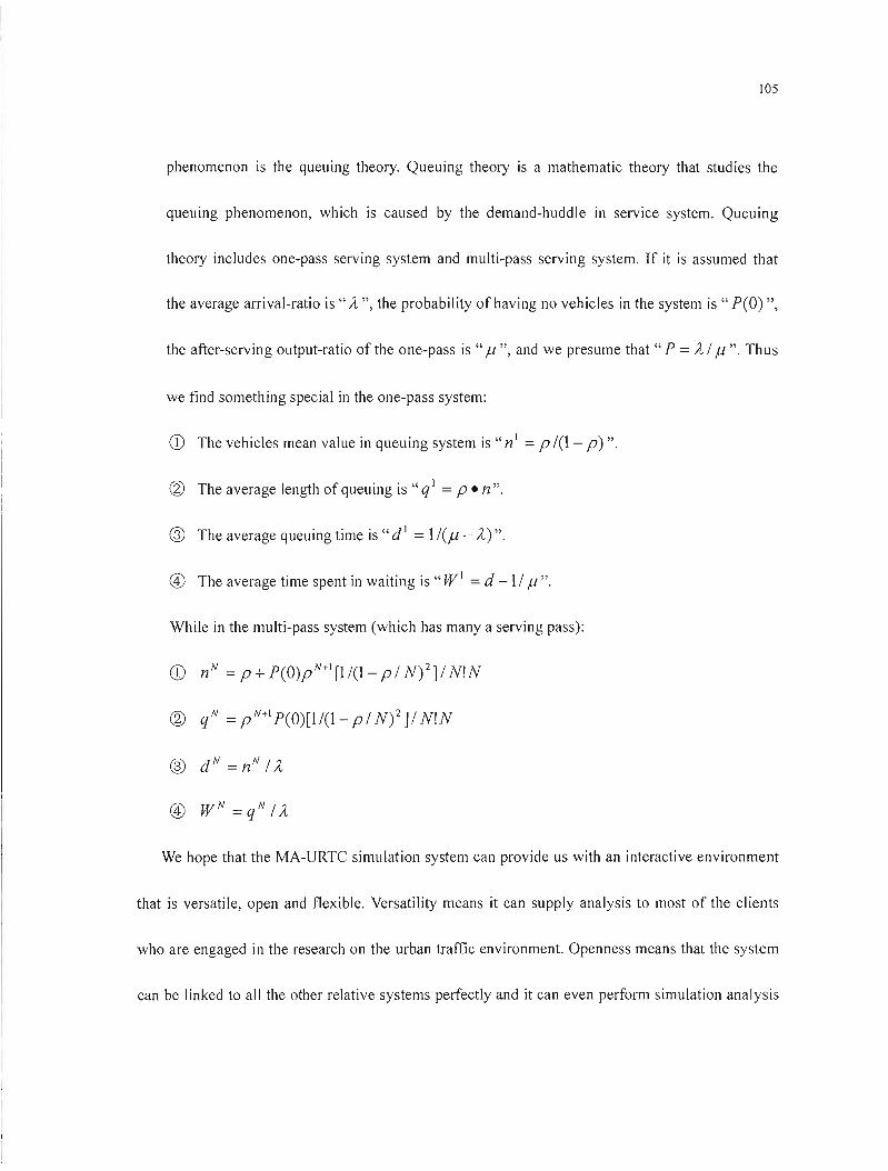
105
phenomenon is the queuing theory. Queuing theory is a mathematic theory that studies the
queuing phenomenon, which is caused by the demand-huddle in service system. Queuing
theory includes one-pass serving system and multi-pass serving system. If it is assumed that
the average arrivaI-ratio is" ÎL", the probability ofhaving no vehicles in the system is "P(O) ",
the after-serving output-ratio of the one-pass is " Ji ", and we presume that " P = ÎL 1Ji ". Thus
we find something special in the one-pass system:
CD The vehicles mean value in queuing system is" nI = pl(l- p)".
@ The average length of queuing is "q 1 = P • n".
® The average queuing time is" dl =1I(Ji - ÎL)".
Ci) The average time spent in waiting is "W 1 =d -11 Ji".
While in the multi-pass system (which has many a serving pass):
CD n N = p + p(O)pN+\ [1/(1- pl N)2]1 N!N
@ qN =pN+lp(O)[1/(l-pIN)2]IN!N
d N® = n N 1ÎL
CV WN=qNIÎL
We hope that the MA-URTC simulation system can provide us with an interactive environment
that is versatile, open and flexible. Versatility means it can supply analysis to most of the clients
who are engaged in the research on the urban traffic environment. Openness means that the system
can be linked to aIl the other relative systems perfectIy and it can even perform simulation analysis
106
by being compatible with other traffic projects. Flexibility refers to the system's capability of
collocating and recombining with ail the applied software and hardware according to ail the
simulation requests.
5.2The Description for the Simulating System
5.2.1 System Development Kit
This simulation system mainly includes the following toolboxes:
• Elementary toolbox: There are five parts in it:
1. Network distributed computer platform.
2. The open GL three-d imensional displaying platform.
3. Database platform.
4. The object-oriented software-developing platform.
5. Computer simulation toolbox.
• Information inputting toolbox: There are three parts in it:
1. Traffic network creating toolbox.
2. Route modeling toolbox.
3. The requested traffic information's input toolbox.
• Simulation toolbox: Jt includes five parts:
107
1. Traffic-flow distributed model storehouse.
2. Microcosmic simulation model storehouse.
3. Output analysis and management toolbox of microcosmic simulation.
4. Visualization toolbox for the two-dimensional simulation
5. Visualization toolbox for the three-dimensional simulation.
5.2.2 Realization of the System's Main Function
• Distributed coordinating and mutual exclusion: It can manage effectively the resource
competition in the system.
• Network function: Its function supports Tep/IP agreements. It can also give enlarged support
to other agreements then deal with the shared data communion successfully among computers.
• Dynamic dispatch: The system's plug-and-play structure can load, uninstall and re-collocate
each of its module cells in the running process and it does not need to intermit other missions.
• To simulate the changes in traffic flow running and the signal controlling process: It is the
basic function of the system and the basis of actualizing other functions. Since this system is a
highly universal one, it should be suitable for realizing the simulation process in the urban
traffic system macroscopically and microcosmically to meet the needs of different members. In
the microcosmic simulation, the system focuses on simulating each of the composing
108
individual's characteristics in the traffic flow. While in the macroscopic simulation, the system
can predigest the simulation on the individual 's characteristics then emphasize particularly on
describing the whole characteristics of the traffic flow. Wh en the system models and evaluates
an integrated traffic project, it often combines these two kinds of simulations with each other
to achieve an optimal result.
• Conformation, storage and management of the traffic network: The traffic network is the most
important and basic part in the traffic flow simulation. The system should be able to finish the
conformation of the traffic network, which includes the alternating production and
modification of the traffic network, the abiding storage of the routine network which means
storing ail the attribute information of the traffic network in the form of database or the outside
data file, the management of the traffic network's memory files. The members can open,
modify and restore the traffic network's data files momentarily.
• Constructing the simulation environment: We must finish constructing the simulation
environment at first before we start simulating the traffic flow. The simulation environment
contains such elements as the traffic network, the quantum of 00, the route-choosing model,
the microcosmic vehicle driving model, the traffic-control timing assignment, the real-time
collected data style and the simulated original point and terminus, etc.
• By simulating the individual vehicle or the traffic flow's driving behaviors on the section of a
road or at the intersection dynamically on the computer, we can re-embody the real-time and
109
dynamic changes on the selected roads, and we can even simulate the inter-disturb driving of
the vehicles at the intersection or on one section of a road.
• Following the terse and perspicuous menu on the screen, we can modify the control parameters
(such as the controlling way of the traffic lights along with the traffic light's green signal ratio,
the intersection 's parameter, passing ratio, the entry and exit parameter on road, etc.) and
determine the simulation relation among the factors of the signal timing, the queuing extent
and delay. So we can adjust on-line the control strategy according to the real-time and dynamic
changes, including the running principle of the traffic flow on the road and at the intersection.
We can make real-time record and display on the statistic number of the traffic flow in the
dynamic simulation process, then calculate and analyze these data using corresponding models
to get the information useful for making strategy. The experimenters can input different kinds
of simulation projects. Then the system chooses the suitable ones from the different simulation
models and methods, data-collecting and evaluating forms to meet different needs of the
members. Meanwhi le this function can provide interface for the new traffic equipments'
inputting. We can even reveal or print out ail these in the form of related figures and forms.
• The maintenance of the model storehouse: The system should supply the members with sorne
existing, common used and relatively mature traffic programming models, route-choosing
models and the microcosmic driving models. Moreover, the system should be responsible for
achieving and managing these models. Before simulating, the members can choose the most
Ilü
suitable model that can meet their needs from the model storehouse in the system to actualize
the traffic flow's simulation. For reliable service, the system is designed to be fault-tolerant at
the 1/0 component level, processor level and the network level.
5.2.3 System's Communication Management Strategy
As the traffic simulation system is responsible for supplying the simulation members with
communication services, therefore as to any exchanged data, the members must be the suppliers or
the consumers. The suppliers only need to provide MA-URTC with data, while the consumers
need to get the data from MA-URTC. And the transferring process is to be done by the simulating
system. The requirements for the design of communication management in the simulation system
should concentrate on its simplicity, reliability and highly practicability, etc.
The thorough process of communication management is: The simulation members exchange
information declaration. ---+ The MA-URTC do the matching calculation and produce information
match ing table. ---+ Establish communication channels and create fi Iter. ---+ The simu lation
members transmit the exchanging data to the MA-URTC ---+ The MA-URTC do matching, filtering
and sending the data. ---+ The simulation members receive the data, etc. Ail the above-mentioned
steps are classified into two parts: the management of the data transmission (refer to the first two
steps) and the dynamic data distribution (refer ta the latter four steps). Jn arder to make the data
111
exchange more real-time, we often set these two kinds services apart from each other. Among them,
we put the management of the data transmission on sorne server in network-MA-URTC_Server;
while the dynamic data distribution-MA-URTC_Local, is distributed on various simulation nodes.
And the MA-URTC_Local runs on the same computer as the simulation member does. When the
MA-URTC_Server has finished the matching of exchanged data and has created the match ing table,
the MA-URTC_Local can get the matching message that is related to the local simulation members
form the MA-URTC_Server; then produce sub matching table and filter. After that, it can establish
communication links with the MA-URTC on the other simulation nodes to create communication
channels. Thus the dynamic data exchange can be transmitted from one node to another directly
without the server 's interference. Figure 5.3 shows the dynamic process of data exchange from
simulation member "A" to "B".
In data exchange, the form of the exchanged data is also an important factor that may
influence the performance of data exchange. According to the systemic architecture of the
simulation system, the members of the system are responsible for maintaining the activities of
related simulation objects in order to represent their behaviors, which is mainly embodied as the
changing course where the objects are staying. There are two primary ways to carry out data
exchange in the system: shared objects' changing state and the communication of interactive event.
The shared object is a simulation-modeling object that is maintained by a simulation member and
whose state transition can be sensed by other related simulation members. This shared object only

112
Simulation Simulation
member of A member ofB
~ ~ Exchange data Exchange data l ,L MA-URTC Local at A MA-URTC- Server MA-URTC Local at B
Sub matching Register table Sub matching
table and filter table and filter
Data application table
Communication Date subscription table Commun ication
channels channels
Exchange dada
\7 V matching table \7 \7 1 Communication network l
Figure 5.3 Data interaction diagram
involves the attributes that is related to other members and should be known by them. So, they are
different from the si mu lating objects that are used by the system 's internai part. Their use is special
for data exchange. Some simulation member produces the interactive event which can be imposed
on other members. The triggered members can repose on the event then accomplish some operation.
The system divides these events into two groups: the simulated interactive events and the system
controlled events. Most of the simulated interactive events are related to the actions of the
113
simulating objects such as the vehicle's going through the detectors, the vehicle's going into or out
of the detecting area and the vehicle's going into or out of the simulating area, etc. The
system-controlled events mainJy refer to aIl the instructions connected with the running of the
system such as the initialization, to load the data, to start the running, to suspend or to resume the
running and to keep clock synchronization, etc.
Each of the simulation members respectively defines a shared object that can be used by other
subsystems or defines the interactive events that may be created. And then it can describe and
explain ail these objects and events information and make the system be responsible for managing
them. Thus, the interactive among ail the simulation members in the system can convert into the
interaction between the shared objects and events. Furthermore, the interactive relation between
them becomes simple and clear, which avoids the direct interference from one object to other
objects in the application of the simulation. The independency of the simulation application system
in developing and running guarantees the realization of the system's flexible further.
5.2.4 Output Results of Simulation System
There are two methods for the outcomes' outputting in MA-URTC system: animation output
and data files output. The animation output is the direct-viewing expression of the outcomes, while
the data files output is the quantitative analysis of the outcomes.
114
5.2.4.1 Animation Output of the Simulation Outcomes
The animation output of the simulation outcomes includes three kinds of entity.
• Static entity: Static entity refers to the entity whose spatial position and state will not change,
for example, the brim of the road, the lane's divisional line, the parking line and the road sign
line, etc. We just need to output these entities once during the whole picture-outputting process
and don 't need to repeat them at each of the simulation intervals. In fact, the static entities are
the backdrop ofthe animation output interface.
• Semi-dynamic entity: Semi-dynamic entity mainly refers to the traffic lights. Although the
position of the traffic 1ights wi Il not change, and we don 't need to repeat its outputting at every
simulation interval, we are expected to change our outputting content--the color of the traffic
Jights at a given moment. The semi-dynamic entity is also the backdrop of the animation
outputting interface.
• Dynamic entity: Dynamic entity refers to the vehicles running within the scope of the
intersection area. In order to reflect the vehicles' movement, we are supposed to output the
pictures of the vehicle in different positions at every simulation interva1.
The animation output of the simulation outcomes is a typical mu Iti-objects movement
displaying in static backdrop. The simulation animation output is mainly connected with the
following techniques:
115
• Realization of the animation output based on the raster operation: The primary method for
actualizing the animation is to scrape the object off from its former position, and then redraws
it in a new position. However superposition of the dynamic and static entity may come up. For
instance, it is very easy for the vehicles, the line of the traffic sign, the lane line and the
parking iine to be in superposition. As a result, if we sim ply scrape the dynamic objects
(vehicles) off from its overlay area, we are bound to synchronously scrape the static objects off
which have been biotted out by the dynamic ones. But if we take the "exclusive or" raster
operating skill, we can solve this problem in a better way. The "exclusive or" raster operating
means to put the new output displaying operate "exclusive or logical" to the stored data in the
revealing card's frame memory together. If we only perform this operation once, we will
scrape the new picture off from the display equipment but will not influence the former
backdrop picture.
• Vibration processing of the animation picture: If the former and latter output images of the
dynamic entity differ greatly from each other in position, or the interval between the former
and later input is a little bit long, there will be vibrating in the picture. Hereby, we should
reduce the position and interval gap of dynamic entity as much as possible in order to reduce
the vibration. It is up to the computer's performance, the clock's set frequency and the
procedure's arithmetic to ascertain the interval between the two successive inputs for dynamic
entity. From the point of procedure designing, we should optimize the arithmetic as much as
116
possible so that the time that is used to calculate the new position of the dynamic entity is less
than that of the c1ock's frequency. For instance, we assume that the computer's clock frequency
to send out an instruction per 100 milliseconds, then it is required that it take less than 100
milliseconds to work out the new position of a dynamic entity in per simulation gap time.
Otherwise, it is impossible for the computer to accomplish the established output although the
instruction has bcen sent out and calculation can't stop either. To reduce the dynamic entity's
fonner and latter position lag, we can do sorne appropriate cutout on the output picture.
5.2.4.2 Data File Output of the Simulation Outcomes
The MA-URTC simulation system has recorded each vehicle's running state at each
simulation interval during the whole simulation period, on grounds of which the system has do ne
sorne statistics to reflect the traffic-changing course on the traffic network. The output data mainly
include the vehicles' speed on each intersection's area in a given period oftime, the queuing length,
the number of queuing vehicle, the delay-time of parking and the parking frequeney.
At present, the system can provide us with a data file output in the form of text file. And we
can perform sorne kinds of analysis on these data, for example, to get sorne simple diagrammatieal
delivery by using other universal software. In the future, we will develop sorne data-output software
that is convenient to make statistic strategies aeeording to the system's application in the real traffie
117
environmenl.
5.2.5 Simulation System Maintenance
It is up to the distributed simulation members to maintain the states of the simulation modeling
objects in the simulation system. The members can actualize the collaboration and interaction
among them by supplying the outside world with the state of the simulation objects or by exploding
sorne relative events. The modeling and simulating on the traffic flow, traffic signal controlling and
the traffic network are indispensable to an integrated traffic simulation system. We believe that the
state of the traffic flow simulation model and the traffic signal controlling agent simulation model
as weil as the traffic network agent simulation model should be the bottommost for the system. In
practice, the users can select different simulation members to configure them together at first then
try to finish the different simulation purposes. Sometimes the users may focus on sorne given
aspects and ignore sorne certain simulation models in the bottommost station as they have on
special requirements for il. In this way, their simu lations may be short of the basic description for
the condition of the simulation objects, and so sorne part of this kind of simulation can hardly get
the information about the outside simulation objects so that it influences the integrality of the
system. However coinstantaneous, as a distributed interactive simulation system, it should also have
the self- completeness at each of the simulation nodes. In the users' opinion, whether the single

118
simulation node (which is not in tightly relationship with the user's purposes) exists or not should
have no influence on the system's running. Therefore, it is very necessary to maintain the integrity
ofthe system.
To actualize the maintenance of the system's integrity, at first we should have such an
understanding as the following: if the users don't perform the selection among the basic modeling
objects, as to the users' specifie simulation needs, the behaviors of these models will not affect the
simulation results greatly. Accordingly, we should develop sorne substitute simulation members that
are simple routine conditions and behaviors that can provide the outside with such kind of
simulation models at any time to sustain the running of the whole system.
Therefore, the maintenance of the integrality in MA-URTC can be divided into five
components: 1. Managing the substitute simulation members. 2. Checking on the integrality of the
system before running. 3. Substitute disposaI of the absent members. 4. Monitoring the integrality
in running. 5. Substitute disposai of the simulation members in running. The management of the
substitute simulation members mainly includes finishing the registering and updating of the
substitute simulation members as weil as storing them in the member-database.
5.3 Simulation Model
As our system is studying to perfection and its big scale, we only introduce a part prototype to

119
explain our design method. We use COMET to design the concurrent, distributed and real-time
traffic system.
5.3.1 Use Case Model
Use case defines the external requirements of the system. In latter modeling analysis, it can
help us determine object participants in the system.
• Driving Control Use Case: Figure 5.4 shows the use case diagram of driving control.
<<us e case pockage» Vehicle C00h01 UseCasePackage
t .,.:;::----;-------{ Driving Control
/\ Vehic1 e-a gent
Determine Vehi cIe State
Figure 5.4 Use case model: Vehicle Control Use Case Package
120
>- Use case's name: Driving Control
Precondition: A vehicle is running.
Brief description: It controls starting, stopping, acceleration, deceleration, turning and
various running speed of a vehicle, which mainly includes free driving, overtaking and
foJlowing.
Substitution: If the vehicle receives an advice about a limited speed on a road, etc, it is to
accept external order. For example, intersection-agent, which the vehicle will arrive at,
informs it to acceJerate or speed down, etc.
Post condition: The vehicle-agent can adjust vehicle' running speed weil according to
real-time requirements and traffic conditions.
>- Use case's name: Determine Vehicle State
Precondition: The vehicle is in the traffic network.
Brief description: (1) Internai timer of vehicle-agent computes periodically the distance
traveled, the number of starting/stopping, the average speed on road and at every
intersection, and the fuel consumption for a trip, etc. (2) Determine the distance from its
neighboring vehicle. (3) When it starts rllnning or enters the traffic network, it selects an
optimal route according to the traffic conditions at that time and is able to make real-time
adjllstments.
Post condition: The vehicle-agent is running weIl.

------
121
>- Use case's name: Communication
Precondition: The vehicle is in the traffic network.
Brief description: The vehicle-agent needs to communicate with intersection-agent, road
agent and other vehicle-agents, which guarantees the vehicle be on the best state.
Post condition: The vehicle-agent is running weil.
• Road Monitoring Use Case: Figure 5.5 shows the use case diagram of road monitoring.
.. lUt' '-aS" p:ld~:.\~l" .-" Ro.la [\Iollilorin~
FSt'c.1SI'Pa,J(.lgf
-----....._.----.,-------------.~.-
( Eni ....· Exil ".
~~I'l'~()p on :.l R()~\1 ". Trame ·Ne(\\"orl.' /i 01' fi Int(ol's~dloll --;:~--:;:--------.--. '-.
-...._---~ -~-----,..--'~""1. ~i .... .. I..::.r..!..~ «(./
----2L ~~.
---~ -'. .......-- '.
1./,'(,.... ~tt'I C.1UCt'I::: • ..J""'" I.. ~·/········· " ..." ..... .+;~::::_.~~_~-- Gnlthllltl' \'dlldé __ ,.~::.:: -f
"~,:/"\"""""::': ..: --................ ----- ,:.'/\,., Rû~d'<lg.CJli"\ '- _, '----,_>--_- _.__:;: ...//
\\ .'.... ( GNlflllh' ..... lùnn (lml Nont)" ) \\\ .... ---------------- --------,-
...-....... \. ---..... . .
\ \
\. \
'. ~--------
<>--..~--- Communié,llIon ----') ._______ ~..r
Figure 5.5 Use case model: Road Monitoring Use Case Package
122
~ Use case's name: Register/Cancellation
Precondition: The simulation system starts running.
Brief description: In a dynamic traffic network, vehicles from different origins go to
different destination. Each road has different traffic flows. A vehicle may not go through
the entire traffic networks, as it may start/stop on different roads or at the intersections.
When a vehicle-agent is running on a road, it is registered to its relative road agents, on
the contrary, when it leaves or stops temporally, it is canceled.
Post condition: Road agents can monitor every vehicle in the traffic network.
~ Use case's name: Guidance Vehicle
Precondition: A vehicle-agent is running on a road and informs his destination to the road
agent.
Brief description: Road agent produces several optimal routes to be selected by the
vehicle-agent. Vehicle-agent makes its selection according to reaJ-time traffic conditions
acquired from other road agent and intersection-agent.
Post condition: The vehicle selects an optimal route to reach its destination.
~ Use case's name: GenerateAlarm and Notify
Precondition: A vehicle-agent is running on the traffie network.
Brief description: (1) When a traffic accident happens on a road, the road agent notifies
the relative intersection-agents that are to forbid other vehicles to enter the entry.
123
Meanwhile other road agents are not to be considered as a part of the route before the
accident is solved. (2) Each road undertakes different traffic functions. Therefore,
limitation of vehicle's speed, types, weight, height, and passing time, etc. is going to be
considered when a vehicle-agent requests a route.
Post condition: The effective alarming and notification raises the efficiency of traffic
simulation system.
}> Use case's name: Data Statistics
Precondition: The system is simulating.
Brief description: (1) Road agent computes real-time traffic flow to inform periodically
connected intersection-agent according to signal cycle in order to the relative
intersection-agent can produce control strategy early. (2) Road-agent produces statistical
data to researcher for studying. For example: the average magnitude of vehicles passing
the road in different time, the probability of traffic accident in a simulated cycle, the
average driving speed, the average length or number of queuing vehicles and the average
speed of entry/exit the area of connected intersection, etc.
Post condition: Road agent has the effective data statistics and updates according to the
different requirements.
}> Use case name: Communication
Precondition: The road agent is running.

----
----------------
124
Sample description: In traffic network, each of road agent needs to interaction and
communicate with other agents or external system. The use case IS fundamental
communication, moreover which subdivides and classifies the relative information ln
order to assure the validity and the rapidity of intelligent transmission. Along with it's the
other function is modify the relative road parameter to test according to requirements of
researchers.
Post condition: Road agent is good communication.
• Signal Control Use Case: Figure 5.6 shows the use case diagram of signal control.
~ us"!' n~f" rn.(J\~l~(' ...
Signal Control FSt'CasePll(I\\l~(,
------. ..".--// Dflhi "1 (/ G{'llt'I")((' Al al'Ill
" Slalblk, ~~ ',~. ']lld Nofify l
~-- ·:j\k.~3'~ ~~'l:("~~--:\' .---_'::..----~-: \,
../(~~ [\[oHjlorin~ _~) \\
......-..- --------~ , ..... \
"\...
.....
\" .,/
\. ---~------------~
Elnt'rf;t'IlCY Pronssine, ··,1---+-----f i \
\'t1tidt,",ig.:m1\::y----~------~----~...
Communie'llion ......... --' -.......~-----~-----
Figure 5.6 Use case model: Signal Control Use Case Package
125
Primary actor: Signal-agent includes intersection-agent and region-agent. Intersection-agent is
the primary signal control and region-agent coordinates these correlative intersection-agents.
Signal-agent start signal control Use Case Package.
Secondary actor: Road agent and vehicle-agent.
~ Use case's name: Monitoring
Precondition: The system starts simulation.
Brief description: It monitors the intersections, which mainly includes the use case of
"data statistics" and "alarming and notification of generation". Date statistics include
traffic signal index computed at the different appraisal cycle, for example the average
delay time and length of queuing, etc, which are helpful for perfecting the system. When
there are exceed-permitted queuing vehicles from a direction or a mere traffic accident
that is to cause traffic jam, it generates alarm and notifies the correlative road agent to
reduce the current traffic pressure in advance. Moreover, it records the vehicle that
violates traffic signal control or driving rules.
Post condition: It meets our monitoring requirements.
~ Use case's name: Signal Control Strategy (Create/Select/Adjust)
Precondition: One or more vehicles arrive at the area of signal control from different
directions.
Brief description: It IS the key of signal control system; every signal-agent creates
126
real-time intelligent control strategy by itself according to traffic conditions. Time
variation is not the only strategy in the urban traffic flow. A universal strategy that can
deal with various real-time conditions is not real. We hope that signal-agent can go to
autonomie selection and real-time adjustment. Once the strategy is determined, it will cali
the use case of signal control to carry out.
Substitution: If mistake of ail intelligent strategies occurs unfortunately, signal-agent will use
traffic-responsive control or fixed time control to rescue.
Post conditions: Urban traffic system is real-time and effective.
~ Use case's name: Modification
Precondition: Studying the urban traffic control.
Brief description: Undoubted, urban intersection 's geometry shape such as the number of
lanes, the width of lane and the channelized layout influences the traffic streams obviously.
Therefore, it helps researchers modify the area layout of an intersection. Tt is not only sure
to synchronization between our control system and practical traffic environment but also
able to advise a good plan in advance. Intersection 's modification should cooperate with
the correlative roads.
Post condition: The modification can satisfy researcher's requirements.
~ Use case's name: Emergency Processing
Precondition: Emergency happens in the urban traffic network.
127
Brief description: An unexpected traffic accident or a vehicle with the urgent mission such
as police's vehicle, fire engines and ambulances ail request special signal control.
Signal-agent must deal with them effectively and immediately. Emergency processing is
superior in the urban traffic control.
Post condition: Emergency is solved and urban traffic fiows restore to the normal order.
~ Use case's name: Communication
Precondition: Starts this control system.
Brief description: This use case is the foundation of cooperation and coordination, which
is essential for the multi-agent. Its function is mainly the bottom connection and
commun ication.
Post condition: Multi-agent are able to real-time interact weil.
As some major use cases mentioned above indieate, we will go on with the perfection
aeeording to researehers' requirements.
5.3.2 Simulation Modeling
We only ehoose part of models: some statie modeling and dynamie modeling. As they are not
eontinuous, we do not indieate the use case of ID. Figure 5.7~5.13 show them.
Figure 5.7 illustrates a static modeling of the high-Ievel traffie control system. This system is a
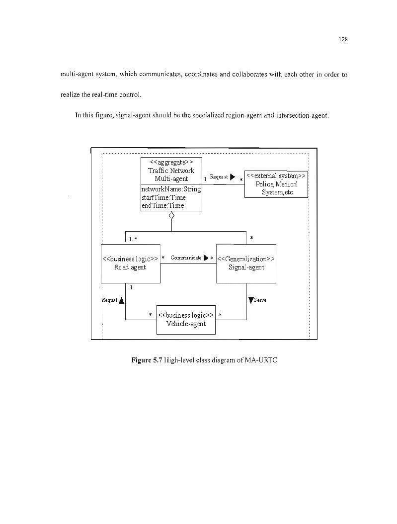
128
mu Iti-agent system, which communicates, coordinates and collaborates with each other in order to
realize the real-time control.
In this figure, signal-agent should be the specialized region-agent and intersection-agent.
« ag gregate> > , , Traffi c Netvvork
1 Request Il'- «extemal system» : Multi -agent * Police, Medical , , networkN ame: String, System, etc. , startTime:Time , ,
endTime:Time ,
, , ,, ,
, y ,
,1..* * , , , ,
«business logic» * Commumcate ~ * <<Genera1izati on> > , Raad agent Signal-agent
,
, , 1 ,, , , ~qust~ ",SelVe
,, ,, * «business logic» * , , Vehicle-agent ,, ,
Figure 5.7 High-Ievel class diagram ofMA-URTC

129
Figure 5.8 illustrates classes corresponding to the above static model. We think that region
agent can demand regionaJ intersection-agent signal control when a special accident occurs.
Therefore, abstract class of signal agent includes signal attribute.
Road agenl {abstr ad}
+roadNum ber:lnteger +or igi nalP ositi on: Str ing +desti nationP osit ion: Stri ng +r oadTy pe: Str ing +lengh:Real +laneNum ber:Real +laneWidlh:Real +vehicleAverageS peed:Real +satur ati orll olum e: Real
+i niti ali zef J{abst ract} +Cüm muni cate()abs tracl} +1 egister (1 +cancel(~ +gui de() abst ract} +m odi fy (J [abslr ad} +Cüm pute[J {abstr ad} +alarmr~olify(J{abslrad} +update( J{abstr ad} -m oni tor [J{abstract} -restore[J{abs lract}
Vehicle- agent {abstr ad}
+num ber:1 nteger +ty pe: SIr ing +or igi nalP ositi on: Str ing +desti nationP osit ion: Stri ng +Wel ght: Real +hei ght: Real +aver ageS peed: Real +cur rentPosi tion: Sting
+initi alize() {abst ract} +Cüm municate(J{abslrad} +r eques 1(J {abstr ad} +Cüm puler{abstr ad} +al arm Noti fy (J {abstr ad} +r esel[J {abstr ad} -conlrol [J {abstr ad} -detect(J {abstract}
S~nal-agent abslr ad}
+type:Slring +num ber: 1nteger +areaParam eter: ReaLString +slate:S tring +cyde:Real +split:Real +phase:Real +offset:Real +di rection: Directi onType +satur ati orll olum e: Real
+i niti ali zef J{abst ract} +Cüm muni cate( J{abstr ad} +Cüntr 01 [J {abstract} +Cüm pute[J {abstr ad} +alarmN otify[J{abstr ad} +moni fy[J{abstract} +update[ J{abstr ad} -m onitor [J {abslractl -display()
Figure 5.8 Attribute and method in abstract class of MA-URTC
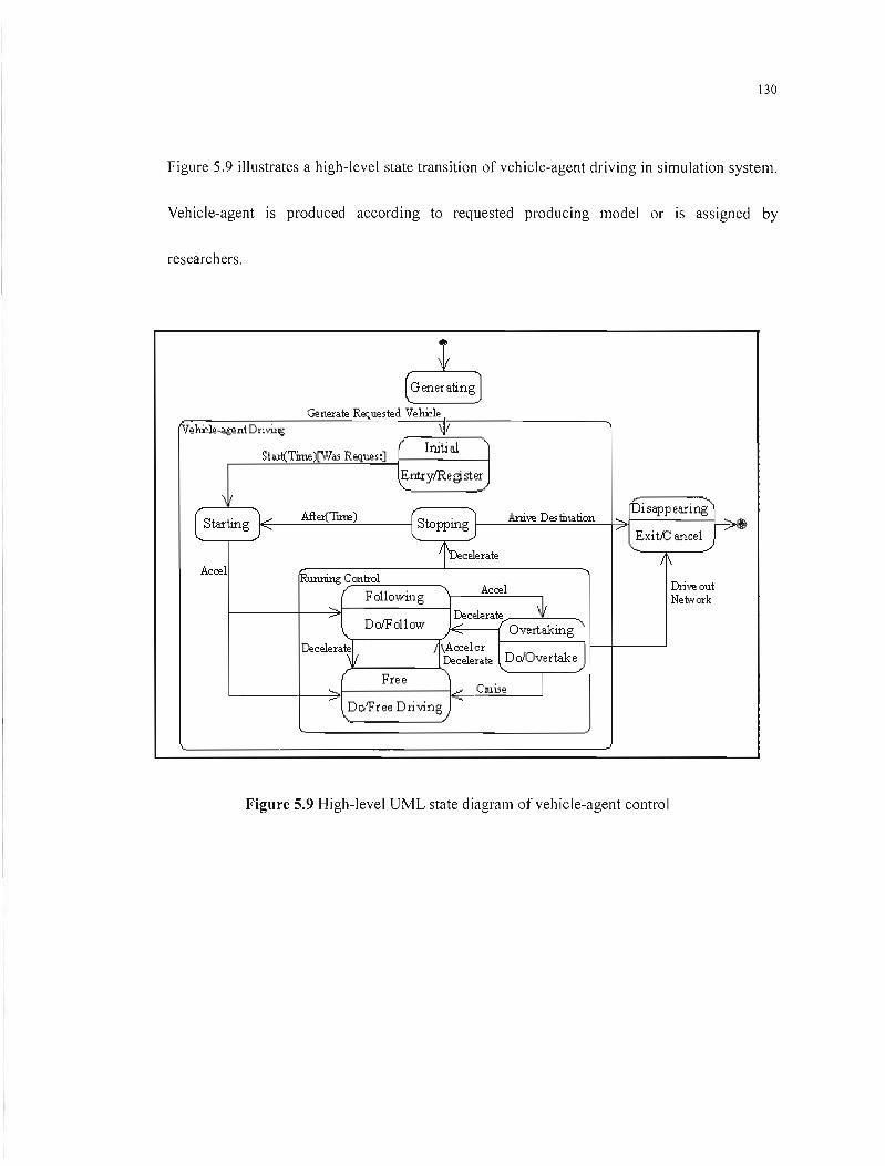
130
Figure 5.9 illustrates a high-Ievel state transition of vehicle-agent driving in simulation system.
Vehicle-agent is produced according to requested producing model or is assigned by
researchers.
t (GeneratingJ
Generale &quesled Ve~le 1
(Ve~le~nt DrivU\g \11 Initial
Sta.tt(Time)[Was Request]
EnU'ylRe gi. ster
\ [bi sapp earing
AfIel{Tnœ) Ani\-~ Des tination[ Starting j ~ (Stopping '1
~ j 1'" ExitJCancel ~ i'necelerale
11\ Acœl
~Contral Ori\!\! out
F0110wing Acœl Ne lwark
,..,. WDecelerale Do/F 011 OW 1....-'
~ Overtaking Decelera~ 1\Accelor
Decelerale DoIOvertake
Free ~ ,..,., ClUise 1
Do/Free Driving ~
Figure 5.9 High-Jevel UML state diagram of vehicle-agent control
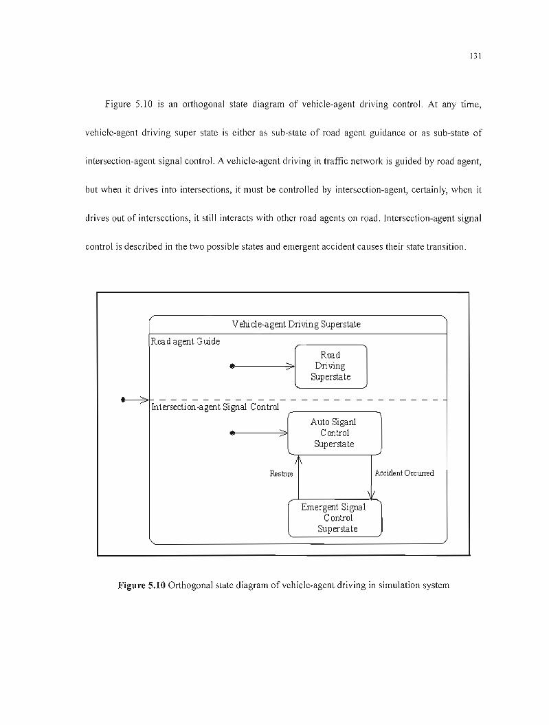
__ _
131
Figure 5.10 is an orthogonal state diagram of vehicle-agent driving control. At any time,
vehicle-agent driving super state is either as sub-state of road agent guidance or as sub-state of
intersection-agent signal controi. A vehicle-agent driving in traffic network is guided by road agent,
but when it drives into intersections, it must be controlled by intersection-agent, certainly, when it
drives out of intersections, it still interacts with other road agents on road. Intersection-agent signal
control is described in the two possible states and emergent accident causes their state transition.
Vehi cl e-agent Drivin g Superstate
Raad agent Guide
Raad Driving
Superstate
A_~'~
--- Intersectian-agent Signal Control
Auto Siganl Cantrol
Superstate
\
Res tore Acciclent Occurred
\1
Emergent Si gnal Control
Superstate
Figure 5.10 Orthogonal state diagram of vehicle-agent driving in simulation system
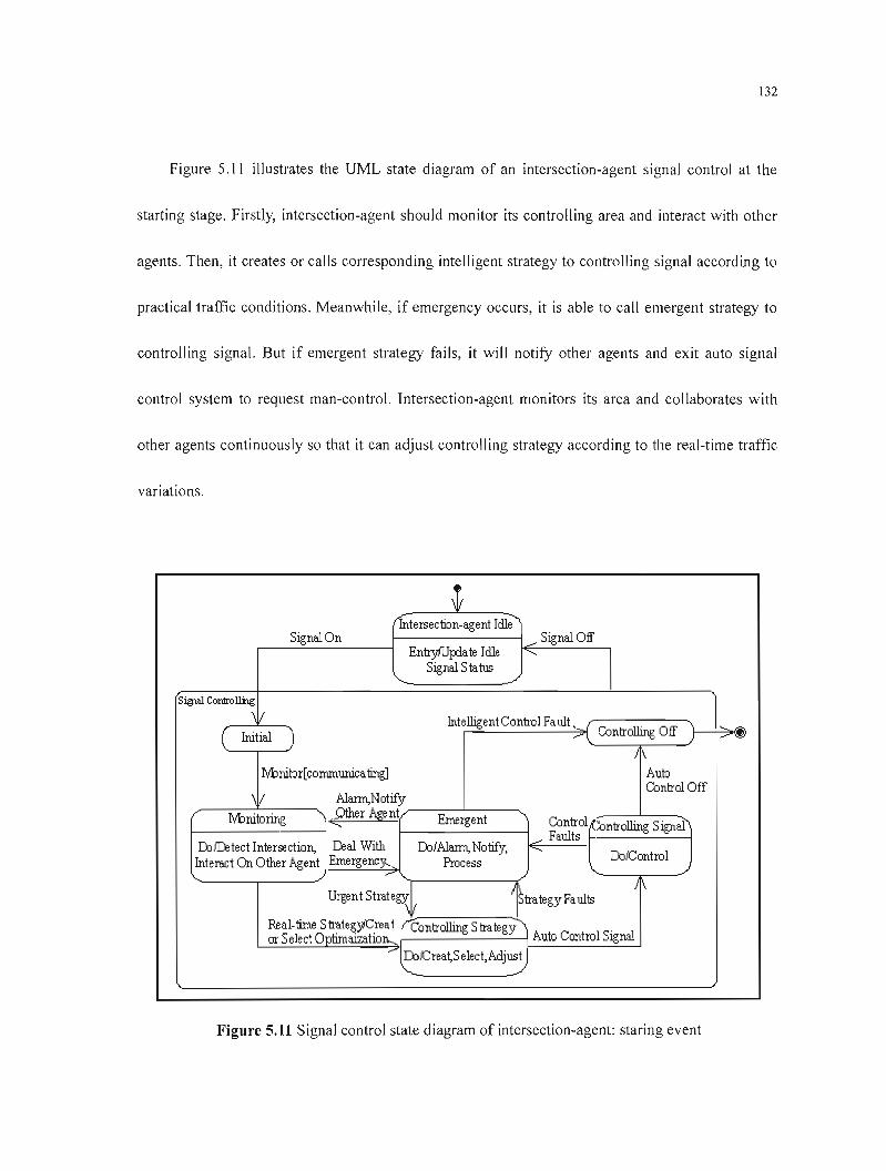
132
Figure 5.11 illustrates the UML state diagram of an intersection-agent signal control at the
starting stage. Firstly, intersection-agent should monitor its controlling area and interact with other
agents. Then, it creates or calls corresponding intelligent strategy to controlling signal according to
practical traffic conditions. Meanwhile, if emergency occurs, it is able to cali emergent strategy to
controlling signal. But if emergent strategy fails, it will notify other agents and exit auto signal
control system to request man-control. Intersection-agent monitors its area and collaborates with
other agents continuously so that it can adjust controlling strategy according to the real-time traffic
variations.
t (futersection-agent Ielle-""
Signal On -" Signal Off EntryfUp:late lelle -....
Signal Sta tus
s~ Cordrolli'lg \/ Intelligent Control Fault. r ... ...".. \. Controlling Off ) -"~( Initial )
~
J\
Nbnitor[conununicating] Auto Control Off
\ 1 Alann,Notify
Nbnitoring '" .9ther Age nt Emergent Control ...:ontrolling Signal....."'"'" ___ Faults
llilD:!tect Intersection, I::eal With D:l/Alann, Notify, '"' D:llControlInteract On Üther Agent Emergenc)'o- Process ,,- ..... ./
Urgent Strate~L ÎStrategy Faults /1\
Renl-time StrategiCreat "'Controlling Strategy or Select Optimaization.." Auto Control Signal
r::olCrea~S elect,Acljust .......
Figure 5.11 Signal control state diagram of intersection-agent: staring event
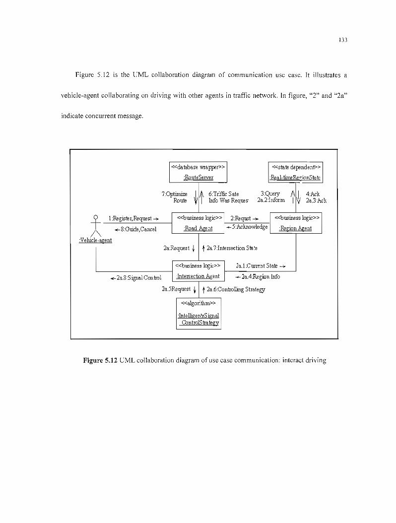
133
Figure 5.12 is the UML collaboration diagram of communication use case. It illustrates a
vehicle-agent collaborating on driving with other agents in traffic network. In figure, "2" and "2a"
indicate concurrent message.
«database wraWP> «state depmden1»
:RouteServer :Real-timeR.egionSta te
7:Opt~ 6Triffic Sate 3:Query 4:Ack Route ~l Wa Wes R.eques· 2a.2:Inform 1\~ 2a.3:Ack
f 1:Register, Request 4 «business logic» 2:Requst_ «business logic»
-of- 8:Guide,Cancel :Road Agent +-5:Acknowledge Region Agent/
:Vehicle-agent " 2a:R.equest t 12a.7:Intersection State
«business logic» 2a.1 :Current State _
<f-2a.8Signal Control :Intersection Agent --2a.4:R.egion Wa
2a5R.equest t t 2a.6:Controlling Strategy
«a1garithm»
:IntelligenteS ignal ContraIS Irategy
Figure 5.12 UML collaboration diagram of use case communication: interact driving
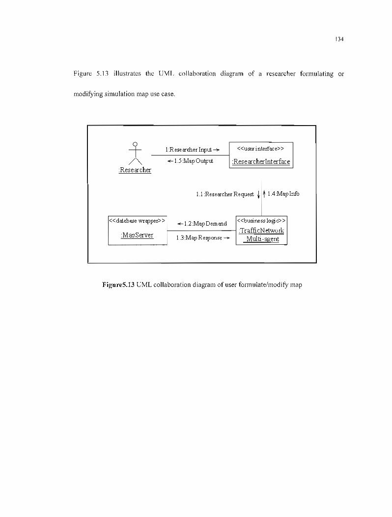
134
Figure 5.13 illustrates the UML collaboration diagram of a researcher formulating or
modifying simulation map use case.
+ 1:Researcher Input. ~ «user interface»
/"'- ~ 1.5 :Map Output. :Researcherlnterface :Researcher
1.1 :Researcher Request t t l.4:MapInfo
«database wrapper>> «business logjc»~ 1.2 :Map 0 em fllld
TrafficN etwork:MapServer 1.3:MapResponse - Multi -agent
FigureS.13 UML collaboration diagram of user formulate/modify map

135
5.4Summary
We discuss about the structure design of the simulation system and its functions to be
actualized as weil as its developing implements in this chapter. It seems practicable to achieve the
simulation system by applying OOP technology to it at present, but it is merely a transitional means.
Our final goal is to achieve the simulation system by the application of AOP technology. As a result,
the structure and mechanism design of the simulation system is very important, and flexibility is the
most important in the design.
136
CHAPTER 6
CONCLUSION AND PROSPECTS
6.1 Thesis Conclusion
Urban real-time traffic control is a general and difficult topic. Research on intelligent urban
traffic control system has numerous academic and practical values. This thesis mainly studies a key
question of intersection signal control in this field based on comprehensively grasping the
developing history and trend. Set up an agent-based traffic control system. Develop an open urban
traffic simulation system, which can adjusts alternately to development oftechnology and needs.
Research products we achieved are mainly:
• We think that multi-agent theory fits for the complex and variable traffic control. It is
obviously advantageous to former concentrated and distributed control system. Meanwhile we
think it's a further advance to hierarchical control system whose sub-systems take on certain
gradation according to superiority, subordination or time order of control. Upper sub-system of
hierarchical control system can be used as a cooperative unit of its under one, determining
coordinated countermeasure and coordinated parameter according to their inter-cooperative
control, while under sub-system needs to transfer feedback about local system environment

137
and control function to its corresponding upper one. Upper sub-system takes these as a
decision basis. The whole system takes on hierarchical control structure. Each of Sub-system
of the same gradation is paralleling distributed and independent. Under sub-system controlled
by upper one is often concentrated and with small number. Hierarchical control system
optimizes concentrated control and distributed one, so it should be the initial control mode for
present complex system. Multi-agent system not only inherits hierarchical control system but
also boosts agent's merits, making it more flexible and effective.
• Seen from materials we grasp, researches using fuzzy control theory on single intersection are
more, so we attempt multi-intersections fuzzy control, which draw useful information from the
actual traffic network information. Make effective use of expert system on based fuzzy strategy
by cooperative communication among closely connected vehicles in intersection-group area, to
coordinate traffic flow among multi-intersections. Real-time intelligent control needs be
applied according to actual situation.
• We observe that although urban traffic has such characteristics as complexity, variability and
high no linearity, etc. we may find out macroscopic law by comparing different hours. For
example, peak-hour traffic occurs in time of relatively fixture while urban areas with great
traffic pressure are fixed which enlighten us a new idea of real-time control. So this thesis
studies how neural network, genetic algorithm, fuzzy control and expert system used in traffic
control. Agent changes control strategy automatically according to changing traffic situation;
138
expelt system provides effective control rules. With simple algorithm, quick decision, fit for
reaJ-time control, decomposition-coordination method to fuzzy control strategy of traffic meets
control requests of normal intersection. As to be in busy and key position but comparatively
isolated intersection, we think ANN-fC strategy has good effects. But if "intersection group"
in sorne area is highly relative with great influence, region-agent plays important role, as can
be seen:
~ Avoid over communication produced by cooperative control among multi-intersection
agents that results in delay. As to present intelligent research level, if we take the whole
area as a neural network model, it cannot meet real-time demands because of so long a
study time and so on. While communication among agents using fuzzy control theory can
reduce the amount and complexity of communication that meets real-time demands.
~ Region-agent acts as cooperation and arbitration, thus avoid over communication among
multi-agents, meanwhile ensure flexibility of each intersection-agent. ft takes a long time
for GA to seek optimization but as we mention above, urban traffic embodies certain
macroscopic. Based on GA optimizing on traffic network, using intell igent neuron model
of neural network to train and study to get optimization in the whole area, then dynamic
select to suitable control strategy for cooperating relative intersections. This can be looked
as cooperative problem solving (CPS). Thus, after the initial period, the system control
effect will be more and more good.

139
Each intelligent control strategy has oneself advantages. We should choose different control
strategy combination according to actual traffic condition. But the key point is to find out the
appropriate "transfer point" that guarantees the real-time traffic control system respond accurately
and running the best of control strategy according to the extraneous information, which needs the
help from the traffic simulation system. We design an open simulation system to meet different
traffic simulation requests; use distributed multi-computer simulation system that differs from most
mono-computer simulation system. We develop intelligent MA-URTC consists of multi-agent of
road, multi-agent of vehicle and multi-agent of signal control to meet requests of actual traffic
environ ment.
6.2Prospeets
We need further research in the following aspects in the future:
6.2.1 Traffie Control Strategy
Artificial intelligent technology is a developing and comprehensive forward course each of
whose products is worth our attention and applying in traffic control after proper reconstruction. Up
to now, associated control strategy of neural network, fuzzy control, GA and expert system needs
140
further perfect of simulation system. Simulation still using OOP but later will use AOP. It uses
agent theory on only partial models but later we'll realize full multi-agent simulation system.
In the future, whi le considering urban public traffic, as to bus-control strategy, we' Il research
on the following: (1) Optimizes the location of bus stop and control coordinately relative vehicle
driving, which is a mainly factor that influence steady movement of traffic flow;(2) In traffic signal
control strategy, consider prior control on bus.
6.2.2 Further Research on Intelligent Agent
According to Schoham and Gerhard Weiss' works, intelligent agent refers to the flexible and
autonomous agent that acts and meets its goal. Agent can be taken as a programming or entity. It is
embedded in environment; feel the environment by sensors; function on the environment by
effectors in order to meet demands.
Traditional intelligent general refers to focusing specifie questions, programming arranges
agent to reason and calculate, which cannot make agent keep greater problem-solving ability in an
open and dynamic environment. Intelligent agent must own metal state to adjust to environmental
changes and cooperative solving.

141
6.2.2.1 Study Traffic Agent's Structure
Gerhard Weiss divides agent into 4 types [17J: logic-based agent, reactive agent, BD! agent and
layering agent. What we should do is to find agent's inward structure that fits for traffic field.
• Logic-based agent: agent decides by logical reasoning. But it has sorne main problems as a
stiff structure; it takes a long time to transfer from reason and decision to operational
programming, which makes it difficult to put it in an environment with strict time limit.
• Reactive agent: Agent's decision-making is realized bya direct mapping from scene to action.
Its merits are simple, economical and easy to process computation, etc. Its demerits are as
agent disposes of problems using short-term view, which make it difficult to learn from
experiences and improve. We think that vehicles distributed in traffic network and inducement
focusing certain vehicle is short-term, while reactive agent's merits just be fit for meeting
mu lti-agent of traffic network needs.
• BD! agent: agent has data structure of B (belief), 0 (desire), 1 (intension) together with
functions showing its deliberation and means-end. Operation on this data structure reaJizes
agent decision-making. BD! agent is a practical reasoning structure whose reason is like daily
used method by man. In our simulation system, we use BD! model to perfect gradual1y
vehicle-agent development.
• Layering agent: ln order to realize agent with reactive and pro-active behavior, one way is to
142
build respectively sub-system of these two behaviors. Organize theses sub-systems into
Jayering structure. Interaction among different layers is allowed. Software's different layers
realize agent's decision-making. Each layer realizes in the different abstract degree to the
reasoning of environment. Generally speaking, there are two kinds of control flows in layering
structure:
~ Horizontal: each software layer is connected with sensor input and action output. Actually,
each layer is like an agent that suggests the agent what to do. The greatest advantage of
horizontal structure is its simple concept. If agent needs embodying n -different kinds of
behavior, then realizes n -different layers. However, as different layers give action choice
through competition, which may make the whole system causing interrupted. So in order
to keep horizontal structure consistent, a mediator function is needed that is used
determine which layer controls agent at any time. So we must consider ail the possible
interaction among layers. If there is n -layers each of which gives m -different actions,
meant, mil -interaction actions must be considered. From design angle, add central
control part means adding bottleneck to agent decision-making. Ail the questions above
can be partially solved in vertical layering structure.
~ Vertical: input and output of sensor is in the charge of one layer respectively. The two
main interactions among layers are bottom-up activation and up-down execution. Thus
reduce complexity of interaction among layers. As there is (n -1 ) interaction in n -Iayers,
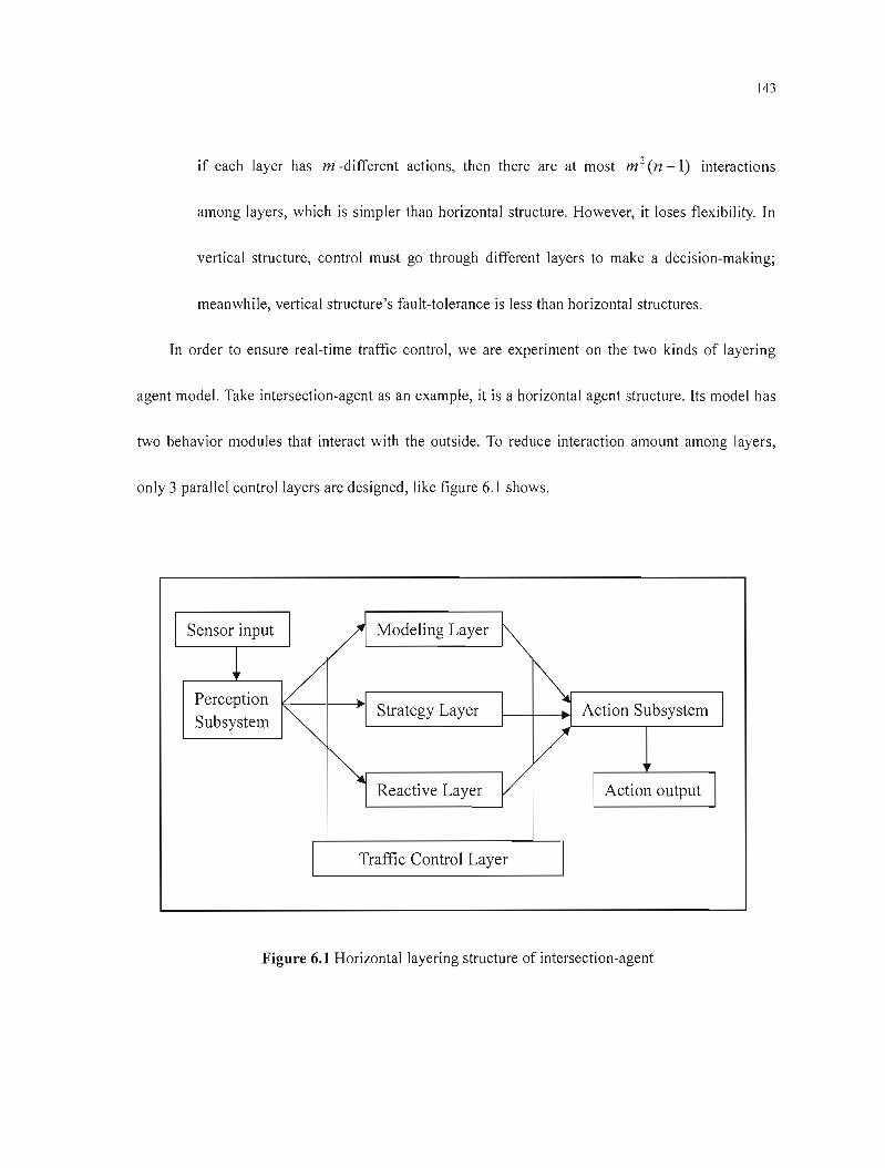
143
if each layer has m -different actions, then there are at most m 2 (n -1) interactions
among layers, which is simpler than horizontal structure. However, it loses flexibility. In
vertical structure, control must go through different layers to make a decision-making;
meanwhile, vertical structure's fault-tolerance is less than horizontal structures.
In order to ensure real-time traffic control, we are experiment on the two kinds of layering
agent mode!. Take intersection-agent as an example, it is a horizontal agent structure. Its model has
two behavior modules that interact with the outside. To reduce interaction amount among layers,
only 3 parallel control layers are designed, like figure 6.1 shows.
Modeling Layer
Strategy Layer Action Subsystem
Reactive Layer Action output
Traffic Control Layer
Figure 6.1 Horizontal layering structure of intersection-agent
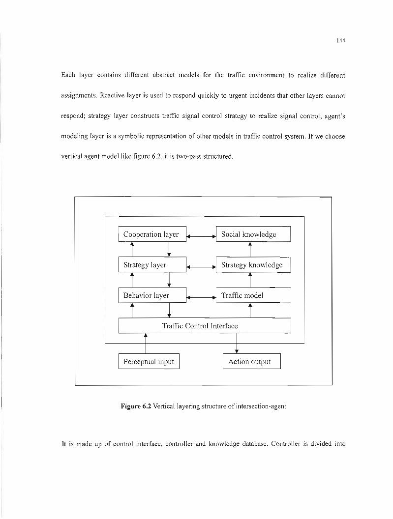
144
Each layer contains different abstract models for the traffic environment to realize different
assignments. Reactive layer is used to respond quickly to urgent incidents that other layers cannat
respond; strategy layer constructs traffic signal control strategy to realize signal control; agent's
modeling layer is a symbolic representation of other models in traffic control system. If we choose
vertical agent model like figure 6.2, it is two-pass structured.
1 Cooperation layer 1 1 Social knowledge 1 1
i l i 1 Strategy layer 1
1
1
1
Strategy knowledge 1
i l i 1 Behavior layer 1
1 .1 1
Traffic model 1
i l i Traffic Control Interface
1 1
1 1 1Perceptual input Action output 1
Figure 6.2 Vertical layering structure of intersection-agent
It is made up of control interface, controller and knowledge database. Controller is divided into
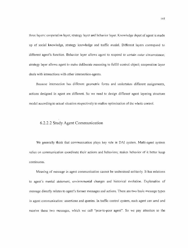
145
three layers: cooperat:on layer, strategy layer and behavior layer. Knowledge depot of agent is made
up of social knowledge, strategy knowledge and traffic model. Different layers correspond to
different agent's function. Behavior layer allows agent to respond to certain outer circumstance;
strategy layer allows agent to make deliberate reasoning to fulfill control object; cooperation layer
deals with interactions with other intersection-agents.
Because intersection has different geometric forms and undertakes different assignments,
actions designed in agent are different. So we need to design different agent layering structure
model according to actual situation respectively to realize optimization of the whole control.
6.2.2.2 Study Agent Communication
We generally think that communication plays key role in DAI system. Multi-agent system
relies on communication coordinate their actions and behaviors; makes behavior of it better keep
continuous.
Meaning of message in agent communication cannot be understood solitarily. ft has relations
to agent's mental statement, environmental changes and historical evolution. Explanation of
message directly relates to agent's former messages and actions. There are two basic message types
in agent commun ication: assertions and queries. In traffic control system, each agent can send and
receive these two messages, which we cali "peer-to-peer agent". So we pay attention to the
146
development of P2P (peer-to-peer). We think that using P2P in traffic control is more effective and
economic than using C/S.
We adopt message communication, which needs improving. At present, semantics and
agreement set for distributed computation environment can offer good service and support, but it
cannot support agent effectively. Because these semantics and agreement is used to deal with
relations among processes or threads rather than deal with programming made up agent or relations
of a series of agents. So an effective agent communication language that can support high-Iayer
communication among agent programming becomes important. Otherwise, agent has to fulfill
transferring from high layer to low one by itself, which costs time and energy. There are differences
among traffic network agent, vehicle-agent, traffic signal control agent and other agents to be
developed in traffic system. In order to exchange message, they needs "public language". It is
demanded be able to îndependent of agent's realization and agent's inner structure. At present,
KQML (knowledge query manipulation language) and ACL (agent communication language) of
FIPA are the two main communication languages in agent system. They are still in improvement till
now. Their semantics are not totally definite. This is also why we use a comparatively mature
technology while developing traffic control system. The worth noting is KQML and ACL are based
on RPC and RMI (RMI is a technology that can be used only for Java platform. If we need to
integrate Java Application procedure and non-Java Application procedure together, using RMI only
cannot do.), which enables them to have the certain limitation in the traffic control system. They
147
demand that aIl nodes participating calculation exist ln the network simu!taneously while
interacting. The whole computation is to fail if sorne necessary resources cannot be visited
temporally. Sine our traffic control is based on mu !ti-agent system, we hope that to better solve
communication problem using mobile agent. Mobile agent can be regarded as a combined product
of software agent and distributed computation technology. It differs from traditional network
computation pattern in essence. It differs from RPC because it can move from one node to another
ln network. Besides, it can choose movement according to own need. It differs from ordinary
process migration because generally speaking ordinary process migration system doesn 't allow
process itseJf to decide when and where to migrate, while mobile agent can move at any time, ln
addition, can move anywhere. Mobile agent differs from applet in java language because applet can
only make single-direction movement from server to client, while mobile agent can make
bi-direction movement between server and client. It activates the design, realization and
maintenance of distributed system. It has many advantages that traditional distributed computation
model doesn 't have:
• Mobile agent can reduce data volume in network greatly. Moving service request agent to goal
main engine makes mobile agent visit resources of main engine directly; reduce interaction
with the source main engine and avoid transference of large volume of data in network, thus
reduce the dependence of the whole system on network band width; shorten communication
delay; raise service quality.
148
• Mobile agent can work autonomously in asynchronous way. We can encapsulate assignments
to be finished into mobile agent, dispatch them in network; and then disconnect source main
engine and goal main engine. Then mobile agent independents of its process that produced it
and operates autonomously in asynchronous way. Source main engine can reconnect with goal
main engine at proper time and receive computation results, which is especially useful to later
traffic control system and mobile equipment (i.e. vehicle) or mobile customers because at
present, computation of mobile equipment ail depends on the expensive and frail network
connection. This needs continuous connection between mobi le equipment and fixed network.
This request isn't reasonable either from economic or technological angle.
• Mobile agent is highly reactive. It can feel its working environment and make proper response
to environmental changes. It can decide dynamically moving goal according to load trends of
server and network, which is good for keeping balanced load. Besides, mobile agent's
intelligent route reduces the judgment that customers are browsing and searching, along with
further strengthens real-time control.
• Mobile agent is good for parallel processing. Mobile agent can dynamically set up several
agents in parallel working while fulfilling a task. Thus, raise efficiency and reduce response
time. Multi-mobile agents have its special capability of dynamically and reasonably distribute
themselves among network main engines. It can dispose optimally the special question
according to certain rules.
149
• Mobile agent has natural isomerism. Distributed network computation platform is often
Isomenc, while mobile agent often independents of the special software and hardware
environment, it depends on its running environment only. So It is suitable for the seamless
system integration.
• Mobile agent is robustness and fault-tolerance. It is able to solve quickly unexpected state and
incident, which makes it easy to set up a distributed system with robustness and fault-toleranee.
When one main engine is closed, aIl mobile agents working on the main engine are alarmed,
and there is enough time for them to move onto another main engine and continue working.
In a nutsheIl, traffic control should be real-time, effective and economical, merits of mobile
agent meets the needs of our future intelligent traffic control. To develop mobile agent that fits for
traffie control is one of our future research directions.
6.3Epilogue
Study on urban real-time traffic control relates to computer, math, auto-control and AI, etc. We
must keep pace with their latest research products and transfer them work for traffic control.
Meanwhile, our research should be divided into two ways: one is to develop real-time traffic control
that can be put into use quickly and produce effects basing on Chinese conditions and technologieal
reality; the other is to face future intelligent traffic control, develop intelligent traffic system in full
150
sense supposing that whatever participates transportation is intelligent. These two ways are not
isolated and don't contradict. The former is basis of the latter while the latter is developing direction
of the former. We need not only to solve the traffic straits we face right now but also go in the
forehead of time because fast development of Chinese economy needs developed traffic control
system that belongs to ourselves.

151
BIBLIOGRAPHY
[1] Ales Leonardis, Horst Bischof. An Efficient MDL-based Construction ofRBF Networks: Neural
Networks. 1998, 11(5): 963-973
[2] Avouris N. M., 1. Gasser. Distribution of Artificial Intelligence: Theory and Praxis. Kluwer
Academic Publishers, 1992
[3] Benderm Edward A. Mathematical Methods Used in Artificial Intelligence. IEEE Computer
Society Press, 1996
[4] Bernd van Linder. "Model Logics for Rational Agents"(PhD thesis). University of Utrecht, 1996
[5] Books, R. A. Intelligence without Representation & Artificial Intelligence, Vo1.47, 1991
[6]Canadian Conference on Electrical and Computer Engineering,
Partl,Montreal,Canada, 1995.190~ 193
[7] CHEN Sen-Fa, CHEN Hong. "Two-Level Fuzzy Control and Simulation for Urban Traffic
Single Intersection". Journal ofSystem Simulation. 1996
[8] Chris Bishop. Improving the generalization properties of radial basis function neural networks.
Neural Computation. 1991,3(4): 579~588
[9] Christoper M. Bishop, Neural Networks for Pattern Recognition. Clarendon Press:Oxford, 1995
[10] Corinne Ledous. An Urban Traffic Flow Model Integrating Neural Networks. Transpn. Res. C,
1997,(5): 287-300
[Il] CUI Yan, HE Guo-guang, WANG Gui-zhu. A Study on the Dynamic Response of an
Intersection under the Certain Condition. SystemsEngineering. May.2002
[12] Daniel W. Rasums. Rethinking Smart Objects: Building Artificial Intelligence with Objects.
Cambridge University, Press, 1999
[13] David Poole, Alan Mackworth, Randy Goebel. Computational Intelligence: A Logical
Approach. Oxford University Press, 1998
152
[14] Dean, T., Allen, J., Aloimonds, Y. Artifical Intelligence: Therory and Practice. Addison-Wesley,
Reading 1995
[15] Dirk Heidemann, Queue Length and Delay Distribution at Traffic Signal, Transpn. Res. -B,
Vo 1.28B, No.5, pp.377-389, 1994.
[16] FENG Wei-dong, HE Guo-guang, LIU Bao. Study on Traffic Flow Based on Self-Organization
Theory. Journal of Systems Engineering, 1998
[17] Gerhard Weiss. Multi-Agent Systems: A modern approach to distributed artificial intelligence.
MIT Press, 1999
[18] H. Levesque. A Logic oflmplicit and Explicit Belief. Proceedings of the National Conference
on Artificial Intell igence, 1984
[19] Haddadi A. S. Communication and Cooperation in Agent Systems. Lecture Notes in Artificial
Intelligence, 1056, Spring-Verlag, 1996
[20] HE Zhen-huan, YANG Zhao-xia, JIANG Xi. Study on Common Simulation System of Land
Traffic & Transportation. Journal of System Simulation, 2002
[21] I-IUANG Hui-xian. The Study on Optimal Method of Urban Traffic Signal Control.
Department of Automatic Control Northwestern Polytechnic University Xi'an ShanXi P R. China,
2000
[22] Jacques Ferber. Multi-Agent Systems: An Introduction to Distributed Aliificial Intelligence.
Addison Wesley, 1999
[23] Jang, J. R. Sun, C., Mizutani, E.. Neuro-Fuzzy and Soft and Soft Computing: A computational
Approach to Learning and Machine Intelligence. Prentice-Hall, 1997
[24] Jerabek Vratislav, Lachiver Gerard. Fuzzy Logic-based Controller of Traffic Intersection.
Proceedings of the 1995
[25] JIA Shun-ping, WANG Li-xing. Computer Simulation and Intelligent Control of City Traffic
Flow. JOURNAL OF NORTHEN JIAOTONG UNIVERSITY. Vo1.23, No.5. Oct 1999.
[26] JIANG Xi, YANF Zhao-Xi. The research of system architecture of synthetic simulation system
153
of civil traffic. Computer Simulation, 2002
[27] Konar, Amit. Artificial Intelligence and soft computing: behavioral and cognitive modeling of
the human brain. CRC Press, 2000
[28] Krishnamoorthy, C. Rajecv. Artificial Intelligence and Expert System for Engineers. CRC
Press, 1996
[29] Labrou Y, Finin T., A semantic approach for KQML-A general purpose communication
language for software agents, In proc. Int. Conf. On information and knowledge management, 1994
[30] Labrou Y, Standardizing Agent Communication, University of Maryland CS Department, 2001
[31] Lesperance Y. etes.. Foundations of a logical approach to agent programming, In Wooldridge
M, etes. editors, Intelligent Agent II (LNAI 1037), Spring-Verlag, 1996
[32] LI Yan, FAN Xiao-Ping. Dynamic Control of Traffic Signal in an Urban Junction Based on
Genetic Aigorithms. Journal of Transportation Systems Engineering and Information Technology,
2002
[33] LIN Si-neng. Simulating Traffic Flow at an Unsignalized T Intersection. Journal of
Guangdong Institute ofTechnology. Dec. 1995
[34] LIU Rong-hui, Dirck Van Vliet, David Watling. Microscopie Day to-Day Dynamic Modelling
of Traffic Assignment and Simulation[C]. Transportation Engineering Technologies, 1998,3:
60-73.
[35] LIU Zhi-yong, ZHU Jin, LI Xiu-pin, YIN Zheng-qi. A Multi-phase Fuzzy Control Method
used for Single Intersection. Information and Controi. Dec. 1999
[36] M. Anthony and N. Biggs. Pac learning and neural networks. In the Hand of Brain Theory and
Neural Networks, Pages 694~697, 1995
[37] MA Xiao-yi, Wang Wei. Simulation Method Applied in the Traffic Capacity of a Priority
Intersection. Journal of Southeast University. Sept.1997
[38] Mary Shaw, David Catlan Software architecture: perspective on an emerging discipline [M],
Qinghua University publishing house, 1998
154
[39] Michael Knapic, Jay Johnson. Development Agent for Distributed Systems. McDraw-Hill,
1998
[40] Mithilesh Jha, Anupam Joshi. A Framework for Dynamic Network Traffic Simulation on
Distributed System [J]. Application of Advanced Technologies in Transportation Engineering. 1998,
(2): 75~89
[4 J] Munindar P. Singh. A Social Semantics for Agent Communication Languages, 1996
[42] Munindar P. Singh. Multi-Agent Systems: A Theoretical Framework for Intentions, Know-How,
and Communications, Lecture Notes in Artifjcial Intelligence, 799, Springer~Verlag, 1994
[43] Nils 1. Nilsson. Artifjcial Intelligence: A New Synthesis. Morgan Kuafmann Publ ishers, Inc,
1998
[44] Nuttall, l, Fellendorf, M. VISSIM for traffic signal optimization. Traffic Technology
International '96. Annual Review Issue. UK, 1996
[45] Pappis.C P, Mamdani E H.A Fuzzy Logic Control1er for a Traffic Junction. IEEE Transactions
on Systems, Man, and Cybernetics, 1977, SMC-7 (l0): 707~717.
[46] Peter Bonsall, Paul Firmin, Monica Anderson, Ian Palmer and Peter Balmforth [J]. Validating
the Results ofa Route Choice Simu1ator, Transportation Research C, 5:371-387.
[47] Raju G V S. Adaptive Hierarchical Fuzzy Controller. IEEE Trans on Systems, Man, and
Cybernetics, 1993, 23(4): 973-980
[48] Rao A. S., Georgeff M. Poo Modelling Agents within A BDI-Architecture, in Lecture Notes in
Artifjcial Intell igence, 1037, Spring-Verlag 1996
[49] Rajiv Khosla, Tharam Di lIon, Engineering Intelligent Hybrid Multi-Agent Systems, Kluwer
Academic Publishers, 1997
[50] Rich, E., Knight, Koo Artificial Intelligence. McGraw-Hill, New York: 1996
[51] SHI Xin-hong, CAl Bai-gen, MU Jian-cheng. Development of Intelligent Transportation
Systems. Journal ofNorthern JiaoTong University. China. 2002
[52] Shoham. AOP: Agent Oriented Programming. Artificial Intelligence, 1993, 60
155
[53] Special Report 209: Highway Capacity Manual. Third edition. TRE, National Research
Council. Washington D C,.1994
[54] Stuart Russell, Peter Norvig. Artificial Intelligence: A Modern Approach. Prentice Hall, 1995
[55] SUN Jin-Wen, LI Ming-Shu, E Zhuo-Mao. The agent-based architecture and simulation
intelligent traffic. Computer Simulation (China). 2002
[56] Vapnik V, Golowich S, Smola A. Support vector method for function approximation,
regression estimation, and signal processing. In: Mozer M, Jordan M, PetscheT (eds). Neural
Information Processing Systems, MIT Press, 1997, 9
[57] WEN Hui-ying, YIN Hong-bin, XU Jian-min. A Method of Fuzzy Traffic Control of
Signalized Intersection. Journal of South China University of Technology (Natural Science Edition).
Dec.2001
[58] Wooldridge M. J.. The Logical Modelling of Computational Multi-Agent Systems. A thesis
submitted to the University of Manchester, 1992
[59] Wooldridge M.. This is MYWORLD: The logics of an Agent-Oriented DAI Tested. ECAI-94
[60] Wooldridge M., Jennings N., J.. Intelligent Agents: TheOl)' and Practice. The Knowledge
Engineering Review, 10(2), 1995
[61] WU Jian-guo, ru Yong-feng. Fuzzy Control and Simulation of the Traffic Signais at the Grade
Crossings. Journal of Xi'an Highway University. Apr.2001
[62] XU Jian-min, SHU Ning, YrN Hong-bin. A New Fuzzy Control Method for Isolated Intersection
Traffic Management. Journal of South China University ofTechnology (Natural Science Edition). June.
2000
[63] YAN Bao-jie, LI Xiao-jun. A Discussion on Mathematical Models in the Simulation Program
ofVehicle Operation at Signal Junction. Journal of Xi'an Highway University. Step.1997
[64] YANG Feng. Evaluation, for urban signalized intersections. Beijing Industry University. China.
2001
[65] ZHAO Yan-e, YANG Zhao-xia, QU Wei-min. Research on Platform of Urban Traffic
Simulation System. Journal of Transportation Systems Engineering and Information Technology.
156
2002,2�
[66] ZHOU Zhi-Jun .. An Object-oriented Development of Urban Traffic Simulation Laboratory
System. Journal of System Simulation. 2002
[67] Zadeh LA. Fuzzy Sets. Information and Control. 1965,8(3): 338~353
[68] ZHOU Guang-wei, YANG Xiao-guang. Micro-model for Vehicle Behavior In urban
Intersection. Journal ofTraffic and Transportation Engineering. Dec.200 1
[69] ZHENG Jie. Chinese Transportation Development Summary. www.jjcc.com.cn. 2004.