
RHTEP-S RHTEPD-S RHTEPE-S RHTEPF-S · 1 hydraulic heads tetes hydrauliques hydraulische köpfe...
20
HYDRAULIC HEADS TETES HYDRAULIQUES HYDRAULISCHE KöPFE CABEZAS HIDRAULICAS TESTE OLEODINAMICHE RHTEP-S RHTEPD-S RHTEPE-S RHTEPF-S ENGLISH FRANÇAIS DEUTSCH ESPAÑOL ITALIANO OPERATION AND MAINTENANCE MANUAL .................................... 3 NOTICE D’UTILISATION ET ENTRETIEN .............................................. 6 BEDIENUNGSANLEITUNG ...................................................................... 9 MANUAL DE USO Y MANTENIMIENTO ........................................... 12 MANUALE D’USO E MANUTENZIONE............................................. 15 19 M 195
Transcript of RHTEP-S RHTEPD-S RHTEPE-S RHTEPF-S · 1 hydraulic heads tetes hydrauliques hydraulische köpfe...

1
HYDRAULIC HEADS
TETES HYDRAULIQUES
HYDRAULISCHE KöPFE
CABEZAS HIDRAULICAS
TESTE OLEODINAMICHE
RHTEP-S RHTEPD-S RHTEPE-S RHTEPF-S
ENGLISH
FRANÇAIS
DEUTSCH
ESPAÑOL
ITALIANO
OPERATION AND MAINTENANCE MANUAL ....................................3
NOTICE D’UTILISATION ET ENTRETIEN ..............................................6
BEDIENUNGSANLEITUNG ......................................................................9
MANUAL DE USO Y MANTENIMIENTO ........................................... 12
MANUALE D’USO E MANUTENZIONE ............................................. 15 19 M
195
2
1 2 3
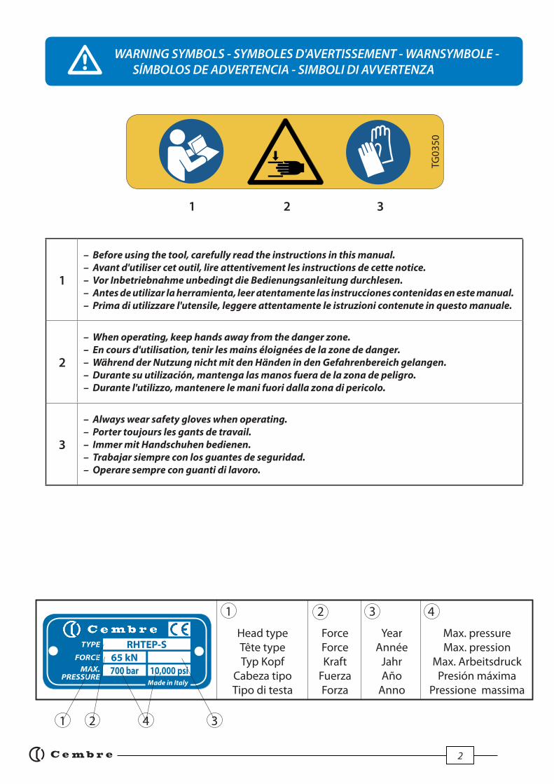
WARNING SYMBOLS - SYMBOLES D'AVERTISSEMENT - WARNSYMBOLE - SÍMBOLOS DE ADVERTENCIA - SIMBOLI DI AVVERTENZA
Head typeTête typeTyp Kopf
Cabeza tipoTipo di testa
YearAnnée
JahrAño
Anno
2 3
1 2 3
Force ForceKraft
FuerzaForza
Max. pressure Max. pression
Max. ArbeitsdruckPresión máxima
Pressione massima
4
41
1
– Before using the tool, carefully read the instructions in this manual.
– Avant d'utiliser cet outil, lire attentivement les instructions de cette notice.
– Vor Inbetriebnahme unbedingt die Bedienungsanleitung durchlesen.
– Antes de utilizar la herramienta, leer atentamente las instrucciones contenidas en este manual.
– Prima di utilizzare l'utensile, leggere attentamente le istruzioni contenute in questo manuale.
2
– When operating, keep hands away from the danger zone.
– En cours d'utilisation, tenir les mains éloignées de la zone de danger.
– Während der Nutzung nicht mit den Händen in den Gefahrenbereich gelangen.
– Durante su utilización, mantenga las manos fuera de la zona de peligro.
– Durante l'utilizzo, mantenere le mani fuori dalla zona di pericolo.
3
– Always wear safety gloves when operating.
– Porter toujours les gants de travail.
– Immer mit Handschuhen bedienen.
– Trabajar siempre con los guantes de seguridad.
– Operare sempre con guanti di lavoro.
TG03
50
RHTEP-S65 kN
TYPE
FORCE
MAX. PRESSURE
10,000 psiMade in Italy
700 bar

3
1. GENERAL CHARACTERISTICS
– Application range: suitable for installing AR... electrical contact bush for railway industry applications.
– Max. operating pressure: ............................................................................................700 bar (10,000 psi) – Oil necessary (displacement): ....................................................................................33 cm3 (2 cu. in.)
– Dimensions: length * ....................................................................................................106 mm (4.1 in.) width .........................................................................................................90 mm (3.5 in.) Ø head ......................................................................................................48 mm (1.9 in.)
– Weight: *.............................................................................................................................1,1 kg (2.4 lbs)
* RHTEPE-S: length 116 mm (4.5 in.); weight 1,2 kg. (2.6 in.)
2. INSTRUCTIONS FOR USE (Ref. to Figs. 1 ÷ 7)
3. CONDUCTOR ASSEMBLY (Ref. to Figg. 8 and 9)
EN
GL
ISH
2.1) SettingThe head is equipped with a "self-lock"quick male coupler suitable for connection to a hydraulic, pneumatic or electrical pump from the Cembre range.
2.2) Drill rail web or, if already drilled, use a suitable reamer to clean the hole (Fig. 1).
2.3) Check the size of the hole with the "GO/NO GO" gauge CAL ....; the hole size is correct only if the green part enters the hole. If the red part enters, the hole is too large (Fig. 2).
2.4) Insert the AR...-1 copper bush into the rail hole (Fig. 3).
2.5) Insert the calibrated plunger OG ... into the bush, on the fl ange side (Fig. 4). Ensure that the ram, in the head is fully retracted. Using the recess in the gauge CAL .... screw and tighten the plunger OG... into the tool head (Fig. 5).
2.6) Operate the pump, to pull the plunger OG ... through the bush and extrude the bush onto the sides of the hole (Fig. 6).
2.7) The bush will also extrude itself around the opposite side of the rail web (Fig. 7).
3.1) Insert the special bolt (with recessed head) through the copper bush. The screw thread should protrude from the fl ange side of the bush; the recessed bolt head will tighten onto the web of the rail and not onto the bush (Fig. 8).
3.2) Crimp the lug onto the conductor. Assemble the lug to the fl ange of the bush over the pro- truding bolt.
3.3) Fit the fl at washer and the self-locking nut. (Fig. 9).

4
4. WARNING
The tool is robust and requires very little daily maintenance. Compliance with the following points should help to maintain the optimum performance of the tool.
4.1) Accurate cleaningDust, sand and dirt are a danger for any hydraulic device.Avoid putting the head on muddy or dusty ground. Any dirt particles may score the ram and cre-ate oil leaks.Every day, after use, the head must be cleaned with a clean cloth, taking care to remove any residual particles, especially around the moving parts.
4.2) Replacement of the automatic couplerTo replace the automatic coupler proceed as follows:– Remove the old coupler.– Carefully clean the thread of the cup (01) to remove the old sealant. – Apply tefl on tape to the thread.– Fit the new automatic coupler (14) and tighten to 30 Nm (22 lbf ft).
4.3) Storage (Ref. to Fig. 11) When not in use, the head should be stored and transported in the steel case, to prevent damage. Steel case: VAL RHTEP: size 230x115xh52 mm (9x4.5x2 in.); weight 0,9 kg. (2 lbs).The case will also store the "GO/NO GO" gauge CAL ... and the two plungers OG ...
The oil pressure in the head must always be completely released before disconnecting the head from the hose.
5. PART LIST (Ref. to Fig. 10)
Code N° Item DESCRIPTION Qty
6840070 01 CUP 1
6360268 02 O-RING 1
6232001 03 LABEL TG.0350 1
04 CYLINDER 1
05 RAM RETURNSPRING 1
06 WASHER 1
6900670 07 SCREW 2 08 RAM 1
Code N° Item DESCRIPTION Qty
09 METAL LABEL 1
6650118 10 ø 2,5x3,5 RIVET 2
6340060 11 M 6x6 GRUB SCREW 1
6040240 12 BACK-UP RING 1
6360320 13 O-RING 1
6060120 14 Q14-MS COUPLER 1
6800186 15 PROTECTION CAP 16000017 SPARE PARTS PACKAGE
The items marked () are those Cembre recommend replacing if the tool is disassembled. These items are supplied on request in the “Spare Parts Package”
The guarantee is void if parts used are not Cembre original spares.
Code N° in the various versions of the head
item RHTEP-S RHTEPD-S RHTEPF-S RHTEPE-S12 RHTEPE-S16
04 6120175 6120175 6120181 6120171 6120171
05 6520341 6520341 6520341 6520430 6520430
06 6641042 6641046 6641042 6641046 6641038
08 6620226 6620226 6620226 6620225 662022509 6232076 6232076 6232246 6232247 6232337
When ordering spare parts always specify the following:- code number of item
- name of item
- type of tool
- tool serial number
EN
GL
ISH
5
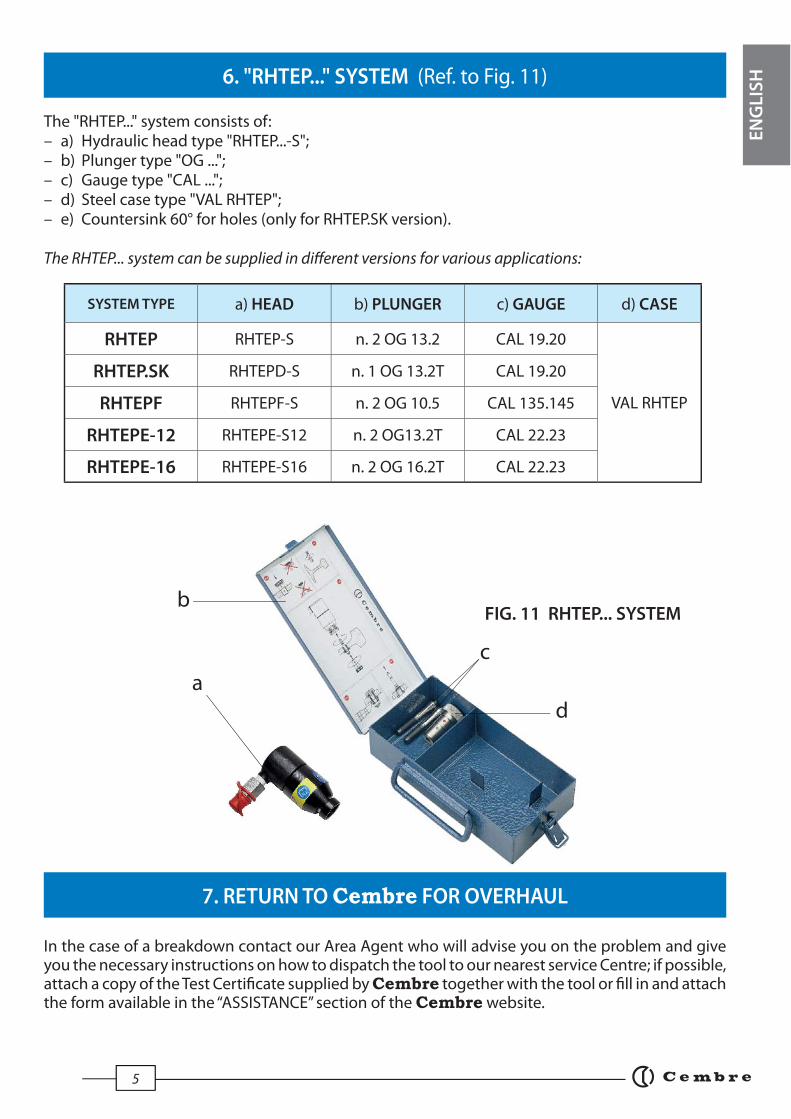
6. "RHTEP..." SYSTEM (Ref. to Fig. 11)
The "RHTEP..." system consists of:– a) Hydraulic head type "RHTEP...-S";– b) Plunger type "OG ...";– c) Gauge type "CAL ...";– d) Steel case type "VAL RHTEP";– e) Countersink 60° for holes (only for RHTEP.SK version).
The RHTEP... system can be supplied in diff erent versions for various applications:
SYSTEM TYPE a) HEAD b) PLUNGER c) GAUGE d) CASE
RHTEP RHTEP-S n. 2 OG 13.2 CAL 19.20
VAL RHTEP
RHTEP.SK RHTEPD-S n. 1 OG 13.2T CAL 19.20
RHTEPF RHTEPF-S n. 2 OG 10.5 CAL 135.145
RHTEPE-12 RHTEPE-S12 n. 2 OG13.2T CAL 22.23
RHTEPE-16 RHTEPE-S16 n. 2 OG 16.2T CAL 22.23
7. RETURN TO Cembre FOR OVERHAUL
In the case of a breakdown contact our Area Agent who will advise you on the problem and give you the necessary instructions on how to dispatch the tool to our nearest service Centre; if possible, attach a copy of the Test Certifi cate supplied by Cembre together with the tool or fi ll in and attach the form available in the “ASSISTANCE” section of the Cembre website.
FIG. 11 RHTEP... SYSTEM
a
b
c
d
EN
GL
ISH

6
1. CARACTERISTIQUES GENERALES
– Domaine d’application: conçue pour l’installation des contacts électriques type AR..., à l’âme des rails.
– Pression max.: .................................................................................................................700 bar (10,000 psi)
– Huile nécessaire (déplacement): ..............................................................................33 cm3 (2 cu. in.)
– Dimensions: longeur * .................................................................................................106 mm (4.1 in.) largeur ......................................................................................................90 mm (3.5 in.) Ø tête ........................................................................................................48 mm (1.9 in.)
– Poids: * ................................................................................................................................1,1 kg (2.4 lbs)
* RHTEPE-S: longeur 116 mm (4.5 in.); poids 1,2 kg. (2.6 in.)
2. INSTRUCTIONS D’ UTILISATION (Voir Fig. 1 ÷ 7)
3. RACCORDEMENT DU CONDUCTEUR (Voir Fig. 8 et 9)
2.1) Mise en service La tête est munie d’un raccord rapide mâle à blocage automatique et peut être reliée aussi bien à des pompes hydrauliques à pied qu’à des pompes pneumo et électro-hydrauliques Cembre.
2.2) Perforer l’âme de rail au diamètre approprié à l’application (Fig. 1). Ebavurer le trou de part et d’autre à l’aide d’une fraise manuelle. Passer un chiff on propre au travers du trou; si le trou a déjà été percé, dresser opportunément la surface du trou.
2.3) Vérifi er la tolérance du trou à l’aide du calibre de réf CAL....; seule la zone VERTE doit entrer (Fig. 2).
2.4) Mettre en place la douille en cuivre étamé réf. AR...-1, en prenant garde à l’orientation de sa partie épaulée (côté arrivée du conducteur) (Fig. 3).
2.5) Introduire l’extrudeur réf. OG... dans la douille, par le côté épaulé de celle-ci (Fig. 4), et le visser dans le piston de la tête en s’aidant du calibre CAL... (Fig. 5). S’assurer que le piston de la tête soit en position de décompression.
2.6) Faire monter en pression l’outil hydraulique de sorte que l’extrudeur OG... pénètre, traverse complètement et ressorte libre de la douille (Fig. 6).
2.7) La déformation du cuivre, subie par le passage en force de l’extrudeur, a permi de réaliser une véritable soudure à froid entre le cuivre et l’acier du rail. Ce “mariage” est intime, étanche et indissociable (Fig. 7).
3.1) Introduire la vis par le côté opposé à l’épaulement de la douille (Fig. 8).
3.2) Sertir la cosse à l’extrémité du conducteur à raccorder.
3.3) Placer successivement sur le boulon, la cosse, la rondelle (rondelle anti-friction pour l’application AR66), l’écrou auto-freiné et serrer au couple préconisé sur la notice de l’ AR... (Fig. 9).
FR
AN
ÇA
IS
7
4. ENTRETIEN
5. PIECES DETACHEES (Voir Fig. 10)
N° Code Pièce DENOMINATION Q.té
6840070 01 EMBASE 1
6360268 02 JOINT TORIQUE 1
6232001 03 ETIQUETTE (TG.0350) 1
04 CYLINDRE 1
05 RESSORT DE RAPPEL PISTONC 1
06 RONDELLE 1
6900670 07 VIS POUR RONDELLE 2 08 PISTON 1
N° Code Pièce DENOMINATION Q.té
09 PLAQUETTE 1
6650118 10 RIVET ø 2,5x3,5 2
6340060 11 VIS SANS TETE M 6x6 1
6040240 12 ANNEAU BK 1
6360320 13 JOINT TORIQUE 1
6060120 14 RACCORD Q14-MS 1
6800186 15 BOUCHON DE PROTECTION 16000017 PAQUET RECHANGE
N° Code dans les diff érent versions de la tête
Pièce RHTEP-S RHTEPD-S RHTEPF-S RHTEPE-S12 RHTEPE-S16
04 6120175 6120175 6120181 6120171 6120171
05 6520341 6520341 6520341 6520430 6520430
06 6641042 6641046 6641042 6641046 6641038
08 6620226 6620226 6620226 6620225 662022509 6232076 6232076 6232246 6232247 6232337
Cette tête est robuste et ne nécessite aucune préoccupation ou entretien particulier.Les recommandations qui suivent sont néanmoins souhaitables pour lui assurer une longévité optimum:
4.1) Nettoyage élémentaireVeiller à protéger l'outil de la poussiére, du sable et de la boue qui sont un danger à tout système hydraulique. Chaque jour après utilisation, l'outil doit être nettoyé à l'aide d'un chiff on propre, tout particulièrement aux endroits de pièces mobiles.
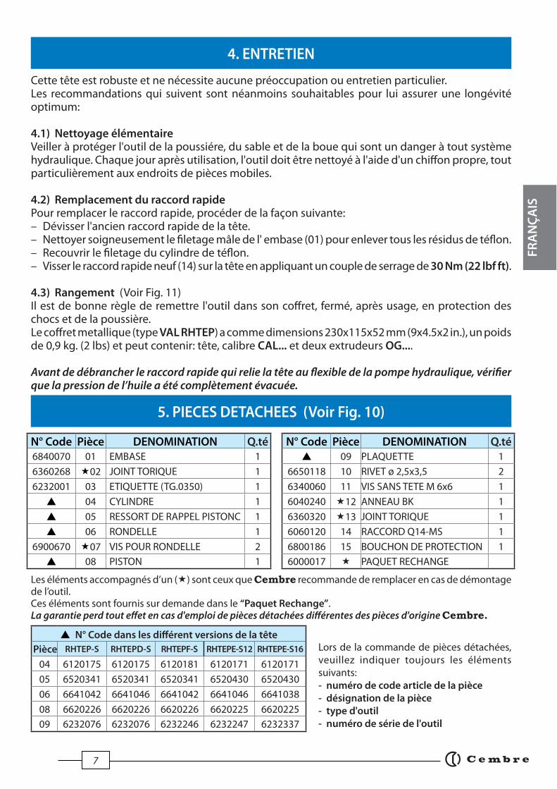
4.2) Remplacement du raccord rapidePour remplacer le raccord rapide, procéder de la façon suivante: – Dévisser l'ancien raccord rapide de la tête. – Nettoyer soigneusement le fi letage mâle de l' embase (01) pour enlever tous les résidus de téfl on. – Recouvrir le fi letage du cylindre de téfl on.– Visser le raccord rapide neuf (14) sur la tête en appliquant un couple de serrage de 30 Nm (22 lbf ft).
4.3) Rangement (Voir Fig. 11) Il est de bonne règle de remettre l'outil dans son coff ret, fermé, après usage, en protection des chocs et de la poussière.Le coff ret metallique (type VAL RHTEP) a comme dimensions 230x115x52 mm (9x4.5x2 in.), un poids de 0,9 kg. (2 lbs) et peut contenir: tête, calibre CAL... et deux extrudeurs OG....
Avant de débrancher le raccord rapide qui relie la tête au fl exible de la pompe hydraulique, vérifi er que la pression de l’huile a été complètement évacuée.
Les éléments accompagnés d’un () sont ceux que Cembre recommande de remplacer en cas de démontage de l’outil.Ces éléments sont fournis sur demande dans le “Paquet Rechange”.La garantie perd tout eff et en cas d'emploi de pièces détachées diff érentes des pièces d'origine Cembre.
Lors de la commande de pièces détachées, veuillez indiquer toujours les éléments suivants:- numéro de code article de la pièce
- désignation de la pièce
- type d'outil
- numéro de série de l'outil
FR
AN
ÇA
IS

8
6. REFERENCE "RHTEP..." (Voir Fig. 11)
ENSEMBLE REF: a) TETE b) EXTRUDEUR c) CALIBRE d) COFFRET
RHTEP RHTEP-S n. 2 OG 13.2 CAL 19.20
VAL RHTEP
RHTEP.SK RHTEPD-S n. 1 OG 13.2T CAL 19.20
RHTEPF RHTEPF-S n. 2 OG 10.5 CAL 135.145
RHTEPE-12 RHTEPE-S12 n. 2 OG13.2T CAL 22.23
RHTEPE-16 RHTEPE-S16 n. 2 OG 16.2T CAL 22.23
7. ENVOI EN REVISION A Cembre
FIG. 11 SYSTEME RHTEP...
a
b
c
d
La référence "RHTEP..." defi nit l'ensemble de:– a) Tête hydraulique "RHTEP...-S";– b) Extrudeur réf. "OG ...";– c) Calibre de contrôle réf. "CAL . ..";– d) Coff ret métallique réf. "VAL R HTEP";– e) Ebavureur 60° pour trous (seulement pour version RHTEP.SK).
L'ensemble RHTEP... peut être fourni en plusieurs modèles diff érents, répondant au diff érents exigences d'emploi:
En cas de dysfonctionnement de l’appareil, merci de vous adresser à notre Agent Régional qui vous conseillera et le cas échéant vous donnera les instructions nécessaires pour envoyer l’appareil à notre Centre de Service le plus proche. Dans ce cas, joindre une copie du Certifi cat d’Essai livré par Cembre avec l’appareil ou remplir et joindre le formulaire disponible dans la section “ASSISTANCE” du site web Cembre.
FR
AN
ÇA
IS
9
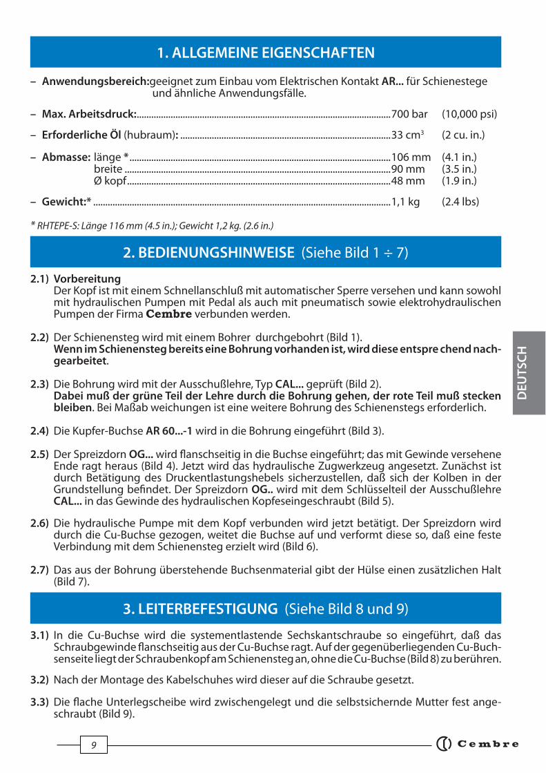
1. ALLGEMEINE EIGENSCHAFTEN
– Anwendungsbereich:geeignet zum Einbau vom Elektrischen Kontakt AR... für Schienestege und ähnliche Anwendungsfälle.
– Max. Arbeitsdruck: .........................................................................................................700 bar (10,000 psi) – Erforderliche Öl (hubraum): .......................................................................................33 cm3 (2 cu. in.)
– Abmasse: länge * ............................................................................................................106 mm (4.1 in.) breite ..............................................................................................................90 mm (3.5 in.) Ø kopf .............................................................................................................48 mm (1.9 in.)
– Gewicht:* ...........................................................................................................................1,1 kg (2.4 lbs)
* RHTEPE-S: Länge 116 mm (4.5 in.); Gewicht 1,2 kg. (2.6 in.)
2. BEDIENUNGSHINWEISE (Siehe Bild 1 ÷ 7)
3. LEITERBEFESTIGUNG (Siehe Bild 8 und 9)
2.1) Vorbereitung Der Kopf ist mit einem Schnellanschluß mit automatischer Sperre versehen und kann sowohl mit hydraulischen Pumpen mit Pedal als auch mit pneumatisch sowie elektrohydraulischen Pumpen der Firma Cembre verbunden werden.
2.2) Der Schienensteg wird mit einem Bohrer durchgebohrt (Bild 1). Wenn im Schienensteg bereits eine Bohrung vorhanden ist, wird diese entspre chend nach- gearbeitet.
2.3) Die Bohrung wird mit der Ausschußlehre, Typ CAL... geprüft (Bild 2). Dabei muß der grüne Teil der Lehre durch die Bohrung gehen, der rote Teil muß stecken bleiben. Bei Maßab weichungen ist eine weitere Bohrung des Schienenstegs erforderlich.
2.4) Die Kupfer-Buchse AR 60...-1 wird in die Bohrung eingeführt (Bild 3).
2.5) Der Spreizdorn OG... wird fl anschseitig in die Buchse eingeführt; das mit Gewinde versehene Ende ragt heraus (Bild 4). Jetzt wird das hydraulische Zugwerkzeug angesetzt. Zunächst ist durch Betätigung des Druckentlastungshebels sicherzustellen, daß sich der Kolben in der Grundstellung befi ndet. Der Spreizdorn OG.. wird mit dem Schlüsselteil der Ausschußlehre CAL... in das Gewinde des hydraulischen Kopfeseingeschraubt (Bild 5).
2.6) Die hydraulische Pumpe mit dem Kopf verbunden wird jetzt betätigt. Der Spreizdorn wird durch die Cu-Buchse gezogen, weitet die Buchse auf und verformt diese so, daß eine feste Verbindung mit dem Schienensteg erzielt wird (Bild 6).
2.7) Das aus der Bohrung überstehende Buchsenmaterial gibt der Hülse einen zusätzlichen Halt (Bild 7).
3.1) In die Cu-Buchse wird die systementlastende Sechskantschraube so eingeführt, daß das Schraubgewinde fl anschseitig aus der Cu-Buchse ragt. Auf der gegenüberliegenden Cu-Buch- senseite liegt der Schraubenkopf am Schienensteg an, ohne die Cu-Buchse (Bild 8) zu berühren.
3.2) Nach der Montage des Kabelschuhes wird dieser auf die Schraube gesetzt.
3.3) Die fl ache Unterlegscheibe wird zwischengelegt und die selbstsichernde Mutter fest ange- schraubt (Bild 9).
DE
UT
SC
H

10
4. WARTUNG
5. ERSATZTEILLISTE (Siehe Bild 10)
Codern Teil BESCHREIBUNG Menge
6840070 01 ZYLINDERDECKEL 1
6360268 02 O-RING 1
6232001 03 AUFKLEBER (TG.0350) 1
04 ZYLINDER 1
05 FEDER 1
06 ANSCHLAGSCHEIBE 1
6900670 07 SCHRAUBE 2 08 KOLBEN 1
Codern Teil BESCHREIBUNG Menge
09 TYPENSCHILD 1
6650118 10 NIET ø 2,5x3,5 2
6340060 11 IMBUSSCHRAUBE M 6x6 1
6040240 12 STÜTZRING 1
6360320 13 O-RING 1
6060120 14 SCHNELLANSCHLUSS Q14-MS 1
6800186 15 STAUBSCHUTZKAPPE 16000017 ARSATZTEILPACKUNG
Codenummer in den verschieden Kopf ausführungen
Teil RHTEP-S RHTEPD-S RHTEPF-S RHTEPE-S12 RHTEPE-S16
04 6120175 6120175 6120181 6120171 6120171
05 6520341 6520341 6520341 6520430 6520430
06 6641042 6641046 6641042 6641046 6641038
08 6620226 6620226 6620226 6620225 662022509 6232076 6232076 6232246 6232247 6232337
Der Kopf ist robust und benötigt keine spezielle Pfl ege oder Instandhaltung. Zur Erhaltung der Garantieansprüche beachten Sie folgende Hinweise:
4.1) Pfl ege Dieses hydraulische Werkzeug sollte vor starker Verschmutzung geschützt werden, da diese für ein hydraulisches System gefährlich ist. Jeden Tag nach der Arbeit sollte das Werkzeug mit einem Tuch von Schmutz und Staub gereinigt werden; besonders die beweglichen Teile.
4.2) Ersatz des SchnellanschlussesWie folgt vorgehen, um den Schnellanschluß zu ersetzen:– Den alten Schnellanschluß des Kopfes losschrauben.– Das Außengewinde des Zylinderdeckels (01) sorgfältig reinigen und die Rückstände der alten Dichtung entfernen. – Ein Tefl on-Band um das Außengewinde wickeln, um die Dichtung erneut herzustellen. – Den neuen Schnellanschluß (14) mit einem Drehmoment von 30 Nm (22 lbf ft) auf dem Kopf einschrauben.
4.3) Lagerung (Siehe Bild 11) Wenn das Werkzeug nicht benötigt wird, sollte es in der abschliessbaren Stahlkassette gelagert werden und ist somit gegen Beschädigungen wie Stoss und Staub geschützt.Die Stahlkassette (Typ VAL RHTEP) hat die Abmasse 230x115x52 mm (9x4.5x2 in.) und ein Gewicht von 0,9 kg. (2 lbs); geeignet zum lagern: hydraulische Kopf, Ausschußlehre CAL..., und n° 2 Spreiz-dorne OG...
Vor dem Schnellanschluß zur Verbindung des Kopfes mit dem Hochdruckschlauch der hydraulischen Pumpe hat man sich zu vergewissern, daß der Öldruck vollständig abgelassen worden ist.
Die mit () gekennzeichneten Bestandteile sind jene, welche Cembre auszuwechseln empfi ehlt, falls das Gerät in seine Bestandteile zerlegt wird. Genannte Einzelteile sind auf Anfrage in der “Ersatzteilpackung” erhältlich.Die Garantie verfällt, wenn nicht Originalteile aus dem Hause Cembre in das Gerät eingebaut werden.
Geben Sie bei der Bestellung aller Ersatzteile folgende Informationen an:- Codenumme r des Ersatzteils
- Beschreibung des Ersatzteils
- Kopf Typ
- Seriennr. vom Kopf
DE
UT
SC
H

11
6. SYSTEM "RHTEP..." (Siehe Bild 11)
SYSTEM TYP a) KOPF b) SPREIZDORN c)AUSSCHUßLEHRE d) KASSETTE
RHTEP RHTEP-S n. 2 OG 13.2 CAL 19.20
VAL RHTEP
RHTEP.SK RHTEPD-S n. 1 OG 13.2T CAL 19.20
RHTEPF RHTEPF-S n. 2 OG 10.5 CAL 135.145
RHTEPE-12 RHTEPE-S12 n. 2 OG13.2T CAL 22.23
RHTEPE-16 RHTEPE-S16 n. 2 OG 16.2T CAL 22.23
7. EINSENDUNG AN Cembre ZUR ÜBERPRÜFUNG
a
b
c
d
Die Bestandteile des System "RHTEP..." sind:– a) Hydraulischer Kopf "RHTEP...-S'– b) Spreizdorn Typ "OG ..."– c) Ausschußlehre Typ "CAL ..."– d) Stahlkassette Typ VAL RHTEP– e) 60° Senker (nur für die RHTEP.SK Ausführung)
Das System RHTEP... kann je nach Anforderungen und Anwendungsbereich in verschiedenen Modellen geliefert werden:
FIG. 11 SYSTEM RHTEP...
Sollten an dem Gerät Fehler auftreten, wenden Sie sich bitte an unsere Gebietsvertretung, die Sie gerne beraten und Ihnen alle nötigen Informationen zum Einsenden des Gerätes an unseren Hauptsitz geben wird. Wenn vorhanden, legen Sie dem Gerät bitte eine Kopie des von Cembremitgelieferten Zertifi kates bei oder füllen das, unter dem Bereich “SUPPORT“ der Cembre Website, verfügbare Formular aus und fügen es bei.
DE
UT
SC
H
12
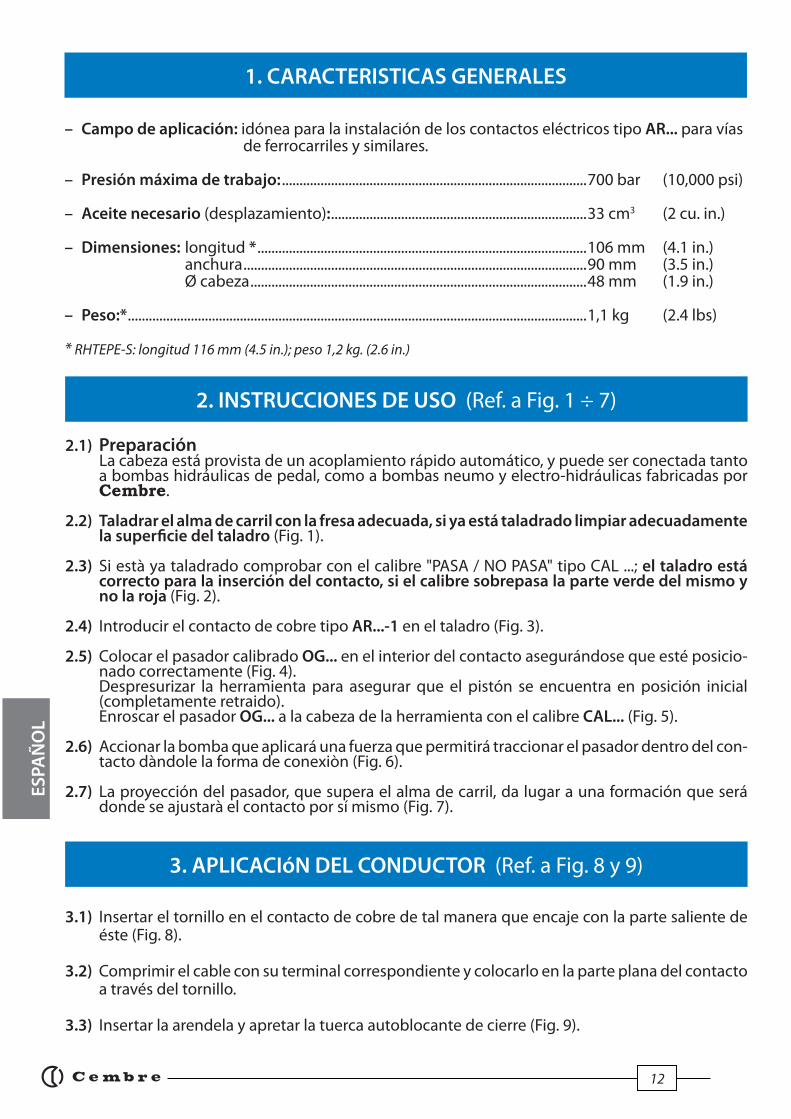
1. CARACTERISTICAS GENERALES
– Campo de aplicación: idónea para la instalación de los contactos eléctricos tipo AR... para vías de ferrocarriles y similares.
– Presión máxima de trabajo: .......................................................................................700 bar (10,000 psi)
– Aceite necesario (desplazamiento): .........................................................................33 cm3 (2 cu. in.)
– Dimensiones: longitud * ..............................................................................................106 mm (4.1 in.) anchura ..................................................................................................90 mm (3.5 in.) Ø cabeza ................................................................................................48 mm (1.9 in.)
– Peso:* ...................................................................................................................................1,1 kg (2.4 lbs)
* RHTEPE-S: longitud 116 mm (4.5 in.); peso 1,2 kg. (2.6 in.)
2. INSTRUCCIONES DE USO (Ref. a Fig. 1 ÷ 7)
3. APLICACIóN DEL CONDUCTOR (Ref. a Fig. 8 y 9)
2.1) Preparación La cabeza está provista de un acoplamiento rápido automático, y puede ser conectada tanto a bombas hidráulicas de pedal, como a bombas neumo y electro-hidráulicas fabricadas por Cembre.
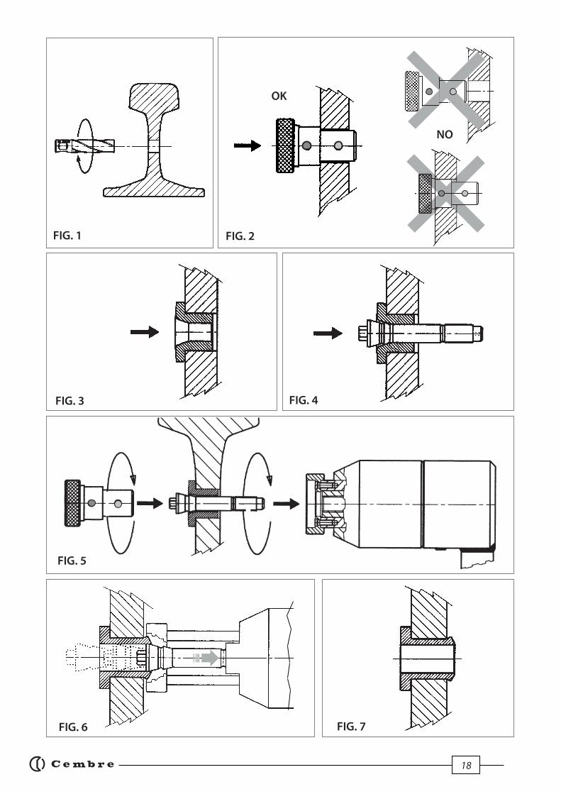
2.2) Taladrar el alma de carril con la fresa adecuada, si ya está taladrado limpiar adecuadamente la superfi cie del taladro (Fig. 1).
2.3) Si està ya taladrado comprobar con el calibre "PASA / NO PASA" tipo CAL ...; el taladro está correcto para la inserción del contacto, si el calibre sobrepasa la parte verde del mismo y no la roja (Fig. 2).
2.4) Introducir el contacto de cobre tipo AR...-1 en el taladro (Fig. 3).
2.5) Colocar el pasador calibrado OG... en el interior del contacto asegurándose que esté posicio- nado correctamente (Fig. 4). Despresurizar la herramienta para asegurar que el pistón se encuentra en posición inicial (completamente retraido). Enroscar el pasador OG... a la cabeza de la herramienta con el calibre CAL... (Fig. 5).
2.6) Accionar la bomba que aplicará una fuerza que permitirá traccionar el pasador dentro del con- tacto dàndole la forma de conexiòn (Fig. 6).
2.7) La proyección del pasador, que supera el alma de carril, da lugar a una formación que será donde se ajustarà el contacto por sí mismo (Fig. 7).
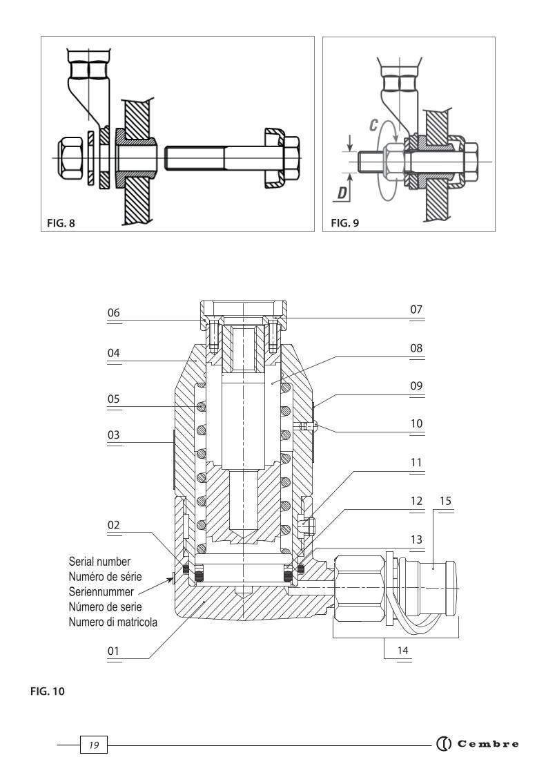
3.1) Insertar el tornillo en el contacto de cobre de tal manera que encaje con la parte saliente de éste (Fig. 8).
3.2) Comprimir el cable con su terminal correspondiente y colocarlo en la parte plana del contacto a través del tornillo.
3.3) Insertar la arendela y apretar la tuerca autoblocante de cierre (Fig. 9).
ES
PA
ÑO
L

13
4. MANTENIMIENTO
5. LISTA DE COMPONENTES (Ref. a Fig. 10)
Codern Eleme. DESCRIPCION C.dad
6840070 01 TAZA 1
6360268 02 JUNTA DE GOMA OR 1
6232001 03 ETIQUETA (TG.0350) 1
04 NDRO 1
05 MUELLE RET. PISTON 1
06 ARANDELA 1
6900670 07 TORNILLO PARA ARANDELA 2 08 PISTON 1
Codern Eleme. DESCRIPCION C.dad
09 TARJETA 1
6650118 10 PASADOR ø 2,5x3,5 2
6340060 11 TORNILLO M 6x6 1
6040240 12 ANILLA DE PLASTICO 1
6360320 13 JUNTA DE GOMA OR 1
6060120 14 ACOPLAMIENTO Q14-MS 1
6800186 15 TAPON DE PROTECCION 16000017 PAQUETE DE REPUESTO
N° Código en la varias versiones de la cabeza
Elem RHTEP-S RHTEPD-S RHTEPF-S RHTEPE-S12 RHTEPE-S16
04 6120175 6120175 6120181 6120171 6120171
05 6520341 6520341 6520341 6520430 6520430
06 6641042 6641046 6641042 6641046 6641038
08 6620226 6620226 6620226 6620225 662022509 6232076 6232076 6232246 6232247 6232337
Esta cabeza es robusta y no requiere cuidados especiales para obtener un funcionamiento correcto, bastará tener algunas precauciones sencillas:
4.1) Limpieza adecuadaTenga presente que el polvo, la arena y la suciedad en general, rapresentan un peligro para toda herramienta hidráulica. Tras cada día de uso, se debe limpiar la herramienta con un trapo limpio, teniendo cuidado de eliminar la suciedad depositada, especialmente junto a las partes móviles.
4.2) Cambio del acoplamiento rápidoPara cambiar el acoplamiento rápido, actuar de la manera siguiente: – Desenroscar el acoplamiento rápido usado de la cabeza. – Limpiar cuidadosamente la rosca macho de la taza (01) para quitar todo residuo de la junta antigua. – Reconstituir la junta en la rosca macho del cilindro con cinta de tefl ón. – Enroscar el acoplamiento rápido nuevo (14) sobre la cabeza apretando con un par 30 Nm (22 lbf ft).
4.3) Almacenamiento (Ref. a Fig. 11) Para proteger la cabeza de golpes accidentales y del polvo cuando no se va a utilizar, es conveniente guardarla en su estuche metalico de cierre hermético.Dicho estuche (mod. VAL RHTEP) de dimensiones 230x115x52 mm (9x4.5x2 in.) y pesa 0,9 kg. (2 lbs); contiene la cabeza, calibre CAL... y dos pasadores calibrados OG... Antes de desensamblar el acoplamiento rápido que une la cabeza al manguera de la bomba hidráu-lica, comprobar que se ha evacuado completamente la presión del aceite.
Los elementos indicados con () son aquellos que Cembre aconseja cambiar en el caso de un posible des-montaje de la herramienta. Estos elementos se suministran bajo pedido en el “Paquete de Repuesto”.La garantía pierde efi cacia si se utilizan piezas de repuesto distintas de las originales Cembre.
Al pedir piezas de repuesto, indicar siempre los elementos siguientes:- número de código del elemento
- designación del elemento
- tipo de cabeza
- número de serie de la cabeza
ES
PA
ÑO
L

14
6. SISTEMA "RHTEP..." (Ref. a Fig. 11)
SISTEMA TIPO a) CABEZA b) PASADOR c) CALIBRE d) CAJA
RHTEP RHTEP-S n. 2 OG 13.2 CAL 19.20
VAL RHTEP
RHTEP.SK RHTEPD-S n. 1 OG 13.2T CAL 19.20
RHTEPF RHTEPF-S n. 2 OG 10.5 CAL 135.145
RHTEPE-12 RHTEPE-S12 n. 2 OG13.2T CAL 22.23
RHTEPE-16 RHTEPE-S16 n. 2 OG 16.2T CAL 22.23
7. DEVOLUCION A Cembre PARA REVISIONES
FIG. 11 SISTEMA RHTEP...
a
b
c
d
Se indica Sistema "RHTEP..." el conjunto de:– a) Cabeza hydraulica "RHTEP...-S";– b) Pasador calibrado tipo "OG ...";– c) Calibre tipo "CAL ...";– d) Caja metálica tipo "VAL RHTEP";– e) Avellanador 60° para taladros (solamente incluido en la versión RHTEP.SK).
El sistema RHTEP... se puede suministrar en diferentes modelos segùn las diferentes exigencias de uti-lización:
En caso de fallo de la herramienta, contactar con nuestro Agente de Zona quien les aconsejará y eventualmente les facilitará las instrucciones necesarias para remitir la herramienta a nuestro centro de servicio más cercano. En tal caso, adjuntar a ser posible una copia del Certifi cado de Ensayo en-tregado en su día por Cembre con la herramienta o completar y adjuntar el formulario disponible en la sección “ASISTENCIA” del sitio web Cembre.
ES
PA
ÑO
L

15
1. CARATTERISTICHE GENERALI
– Campo di applicazione: adatta all' installazione di contatti elettrici tipo AR.... su rotaie e/o apparecchi del binario.
– Pressione massima di esercizio: ...............................................................................700 bar (10,000 psi) – Olio richiesto (cilindrata): ............................................................................................33 cm3 (2 cu. in.)
– Dimensioni: lunghezza * .............................................................................................106 mm (4.1 in.) larghezza ..................................................................................................90 mm (3.5 in.) Ø testa .......................................................................................................48 mm (1.9 in.)
– Peso:* ...................................................................................................................................1,1 kg (2.4 lbs)
* RHTEPE-S: lunghezza 116 mm (4.5 in.); peso 1,2 kg. (2.6 in.)
2. ISTRUZIONI PER L’USO (Rif. a Fig. 1 ÷ 7)
3. APPLICAZIONE DEL CONDUTTORE (Rif. a Fig. 8 e 9)
2.1) Preparazione: La testa è provvista di innesto rapido maschio con bloccaggio automatico e può essere con- nessa sia a pompe oleodinamiche a pedale, sia a pompe pneumo o elettrooleodinamiche di costruzione Cembre.
2.2) Forare il gambo della rotaia con una punta oppure, se questo è gia forato, ravvivare oppor- tunamente la superfi cie del foro (Fig. 1).
2.3) Verifi care col calibro avvitatore CAL ... che il foro nella rotaia sia in tolleranza (deve passare la parte verde - non deve passare la parte rossa) (Fig. 2).
2.4) Applicare nel foro del gambo della rotaia la bussola di rame AR...-1 (Fig. 3).
2.5) Introdurre l’ogiva d’espansione calibrata OG ... dal lato fl angiato della bussola facendone fuo- riuscire l’estremità fi lettata (Fig. 4). Assicurasi che il pistone della testa sia completamente arretrato. Avvitare l’ogiva OG ... nella sede fi lettata della testa mediante l’apposito calibro avvitatore CAL ... (Fig. 5).
2.6) Azionare la pompa collegata alla testa. Viene esercitata in questo modo una trazione dell’ogiva OG ... che passa attraverso il foro della bussola di rame deformandola fi no ad ottenere un ac- coppiamento intimo con la rotaia (Fig. 6).
2.7) La porzione eccedente della bussola che sborda dal foro crea un ulteriore agggancio con la rotaia stessa (Fig. 7).
3.1) Inserire nella bussola in rame la vite con testa esagonale scaricata in modo che il fi letto sporga dal lato fl angiato della bussola; la testa della vite circonderà, senza toccarla, la parte sbordante della bussola (Fig. 8).
3.2) Intestare il cavo con il capocorda e posizionarlo sulla bussola con la vite nel foro d’attacco.
3.3) Inserire la rondella piana e serrare il dado autofrenante (Fig. 9).
ITA
LIA
NO

16
4. AVVERTENZE
5. LISTA DEI COMPONENTI (Rif. a Fig. 10)
N° Cod. Part DESCRIZIONE Q.tà
6840070 01 TAZZA 1
6360268 02 GUARNIZIONE OR 1
6232001 03 ETICHETTA (TG.0350) 1
04 CILINDRO 1
05 MOLLA RITORNO PISTONE 1
06 RONDELLA 1
6900670 07 VITE 2 08 PISTONE 1
N° Cod. Part DESCRIZIONE Q.tà
09 TARGHETTA 1
6650118 10 RIVETTO ø 2,5x3,5 2
6340060 11 GRANO M 6x6 1
6040240 12 ANELLO BK 1
6360320 13 GUARNIZIONE OR 1
6060120 14 INNESTO RAPIDO Q14-MS 1
6800186 15 TAPPO DI PROTEZIONE 16000017 CONFEZIONE RICAMBIO
N° Codice a seconda della versione della testa
Part RHTEP-S RHTEPD-S RHTEPF-S RHTEPE-S12 RHTEPE-S16
04 6120175 6120175 6120181 6120171 6120171
05 6520341 6520341 6520341 6520430 6520430
06 6641042 6641046 6641042 6641046 6641038
08 6620226 6620226 6620226 6620225 662022509 6232076 6232076 6232246 6232247 6232337
La testa è robusta e non richiede attenzioni particolari; per garantirne un corretto funzionamento basterà osservare alcune semplici precauzioni:
4.1) Accurata puliziaTenere presente che la polvere, la sabbia e lo sporco rappresentano un pericolo per ogni apparec-chiatura oleodinamica.Evitare di appoggiare direttamente la testa su terreni fangosi o polverosi. Eventuali depositi solidi possono infatti provocare la rigatura del cilindro con conseguenti perdite di olio.Dopo ogni giorno d’uso si deve ripulire la testa con uno straccio pulito, avendo cura di eliminare lo sporco depositatosi su di esso, specialmente vicino alle parti mobili.
4.2) Sostituzione dell'innesto rapidoPer sostituire l'innesto rapido operare come segue:– Svitare l'innesto rapido vecchio della testa. – Pulire accuratamente la fi lettatura maschio della tazza (01) rimuovendo ogni residuo della vecchia guarnizione.– Ricostituire la guarnizione sulla fi lettatura maschio del cilindro con nastro di tefl on.– Avvitare l'innesto rapido nuovo (14) sulla testa serrando con coppia 30 Nm (22 lbf ft).
4.3) Custodia (Rif. a Fig. 11)Per proteggere l’utensile da urti accidentali e dalla polvere, quando non viene utilizzato, è bene custodirlo nell’apposita cassetta metallica accuratamente chiusa.Questa cassetta (tipo VAL RHTEP) ha dimensioni 230x115xh52 mm (9x4.5x2 in.) e pesa 0,9 kg. (2 lbs); contiene,oltre alla testa, il calibro avvitatore CAL ... e due ogive calibrate tipo OG ...
Prima di sconnettere l’innesto rapido che allaccia la testa al tubo della pompa oleodinamica, veri-fi care che la pressione dell’olio sia stata completamente rilasciata.
I particolari indicati con () sono quelli che la Cembre consiglia di cambiare sempre nel caso di un eventuale smontaggio dell'utensile. Detti particolari sono fornibili su richiesta nella “Confezione Ricambio“.La garanzia decade qualora vengano utilizzate parti di ricambio non originali Cembre.
Per ordinare parti di ricambio, specifi caresempre i seguenti punti:- numero di codice del componente
- denominazione del componente
- tipo dell'utensile
- numero di matricola dell'utensileITA
LIA
NO

17
6. SISTEMA "RHTEP..." (Rif. a Fig. 11)
Sistema Tipo a) TESTA b) OGIVA c) CALIBRO d) CASSETTA
RHTEP RHTEP-S n. 2 OG 13.2 CAL 19.20
VAL RHTEP
RHTEP.SK RHTEPD-S n. 1 OG 13.2T CAL 19.20
RHTEPF RHTEPF-S n. 2 OG 10.5 CAL 135.145
RHTEPE-12 RHTEPE-S12 n. 2 OG13.2T CAL 22.23
RHTEPE-16 RHTEPE-S16 n. 2 OG 16.2T CAL 22.23
7. RESA ALLA Cembre PER REVISIONE
FIG. 11 SISTEMA RHTEP...
a
b
c
d
Si defi nisce Sistema "RHTEP..." l'assieme di:– a) Testa oleodinamica "RHTEP...-S";– b) Ogiva calibrata tipo "OG ...";– c) Calibro tipo "CAL ...";– d) Cassetta metallica di contenimento tipo "VAL RHTEP";– e) Svasatore 60° per fori (solo per versione RHTEP.SK).
Il sistema RHTEP... è disponibile in varie versioni, per le diverse esigenze d'impiego:
In caso di guasto contattare il nostro Agente di Zona il quale vi consiglierà in merito e fornirà le istruzioni necessarie per l’invio dell’utensile alla nostra Sede; se possibile, allegare copia del Certi-fi cato di Collaudo a suo tempo fornito dalla Cembre con l’utensile oppure, compilare ed allegare il modulo disponibile nella sezione “ASSISTENZA” del sito web Cembre. IT
AL
IAN
O
18
FIG. 1 FIG. 2
FIG. 5
FIG. 4
FIG. 6 FIG. 7
FIG. 3
OK
NO
19
11
13
08
07
09
10
12
01
02
05
04
06
03
14
15
FIG. 9FIG. 8
FIG. 10

20
cod.
626
1071
20
cod.
626
1071
This
man
ual i
s the
pro
pert
y of
Cem
bre:
any
repr
oduc
tion
is fo
rbid
den
with
out w
ritte
n pe
rmis
sion
.Ce
man
uel e
st la
pro
prie
té d
e Cem
bre:
tout
e re
prod
uctio
n es
t int
erdi
te sa
uf a
utor
isat
ion
écrit
e.D
iese
Bed
ienu
ngsa
nlei
tung
ist E
igen
tum
der
Firm
a Cem
bre.
Ohn
e vo
rher
ige
schr
iftlic
he G
eneh
mig
ung
darf
die
Bed
ienu
ngsa
nlei
tung
wed
er v
olls
tänd
ig n
och
teilw
eise
ver
viel
fälti
gt w
erde
n.Es
te m
anua
l es p
ropi
edad
de Cem
bre.
Tod
a re
prod
ucci
ón e
stá
proh
ibid
a si
n au
toriz
ació
n es
crita
.Q
uest
o m
anua
le è
di p
ropr
ietà
del
la Cem
bre:
ogn
i rip
rodu
zion
e é
viet
ata
se n
on a
utor
izza
ta p
er sc
ritto
.
Cembre Ltd.Dunton ParkKingsbury Road, Curdworth - Sutton ColdfieldWest Midlands B76 9EB (UK)Tel.: 01675 470440 - Fax: 01675 470220E-mail: [email protected]
Cembre S.p.A. Via Serenissima, 925135 Brescia (Italia)Telefono: 030 36921Telefax: 030 3365766E-mail: [email protected]
Cembre S.a.r.l.22 Avenue Ferdinand de Lesseps91420 Morangis (France) Tél.: 01 60 49 11 90 - Fax: 01 60 49 29 10CS 92014 - 91423 Morangis CédexE-mail: [email protected]
Cembre España S.L.U.Calle Verano 6 y 828850 Torrejón de ArdozMadrid (España)Teléfono: 91 4852580 - Fax: 91 4852581E-mail: [email protected]
Cembre GmbH Heidemannstraße 16680939 München (Deutschland)Telefon: 089 3580676Telefax: 089 35806777E-mail: [email protected]
Cembre Inc. Raritan Center Business Park181 Fieldcrest AvenueEdison, New Jersey 08837 (USA)Tel.: (732) 225-7415 - Fax: (732) 225-7414E-mail: [email protected]
www.cembre.com
IKUMA GmbH & Co. KG Boschstraße 771384 Weinstadt (Deutschland)Telefon: 07151 20536-60Telefax: 07151 20536-80E-mail: [email protected]