QUIETOR - Profroid · applIcaTIOn Les QUIETOR City sont des groupes de ... • Départs postes...
12
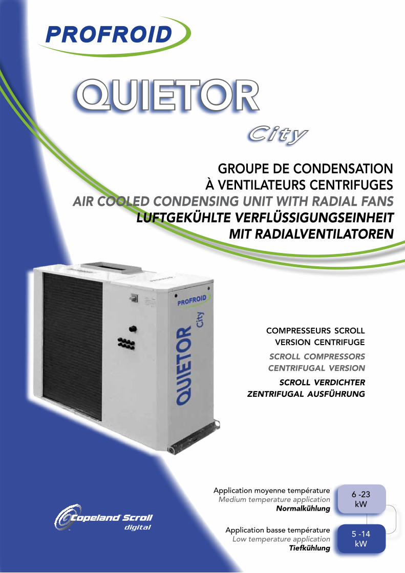
QUIETOR City GROUPE DE CONDENSATION À VENTILATEURS CENTRIFUGES AIR COOLED CONDENSING UNIT WITH RADIAL FANS LUFTGEKÜHLTE VERFLÜSSIGUNGSEINHEIT MIT RADIALVENTILATOREN COMPRESSEURS SCROLL VERSION CENTRIFUGE SCROLL COMPRESSORS CENTRIFUGAL VERSION SCROLL VERDICHTER ZENTRIFUGAL AUSFÜHRUNG Application moyenne température Medium temperature application Normalkühlung Application basse température Low temperature application Tiefkühlung 6 -23 kW 5 -14 kW
-
Upload
nguyenngoc -
Category
Documents
-
view
217 -
download
0
Transcript of QUIETOR - Profroid · applIcaTIOn Les QUIETOR City sont des groupes de ... • Départs postes...
blue:pantone 072CCMYK 100, 88, 0, 5green:pantone 362CCMYK 50, 0, 100, 10
QUIETORCi ty
gROUpE dE cOndEnsaTIOn à vEnTIlaTEURs cEnTRIfUgEs
air Cooled Condensing unit with radial fansluftgeKÜhlte VerflÜssigungseinheit
mit radialVentilatoren
compresseurs scrollversion centrifuge
scroll compressorscentrifugal version
scroll verdichterzentrifugal ausführung
Application moyenne températureMedium temperature application
normalkühlung
Application basse température Low temperature application
tiefkühlung
6 -23kW
5 -14kW

aPPliCation
The QUIETOR City are low noise condensing units specially designed for small supermarket :
•Designedforinstallationinside
(ductable mounting)
•Medium(R404A/R407F/R134a)andlow temperatureapplications(R404A/R407F).
•CEmarked.
main Benefits
• Ducted installation
anwendungsBereiCh
DieAnlagenderBaureiheQUIETORCity sind Verflüssigungseinheiten mit geringer Geräuschentwicklung, die eigens für den Einsatz in kleinen Supermärkten konzipiert wurden:
•FürInnenaufstellungvorgesehen (LuftkanalAnschluss)
•UmfasstdieBereicheNormalkühlung (R404A/R407F/R134a)undTiefkühlung (R404A/R407F).
•CE-Kennzeichnung.
hauPtVorteile
• Installation des Kanals
applIcaTIOn
Les QUIETOR City sont des groupes de condensation silencieux spécialement étudiés pour l’équipement de petits supermarchés :
• Conçus pour être installés à l’intérieur et pour être raccordés par gaines
• Couvrant les applications à moyennes
(R404A/R407F/R134a) et basses températures (R404A/R407F).
• Marquage CE.
avanTagEs pRIncIpaUX
• Installation avec gaine
avanTagEs pRIncIpaUX main Benefit
hauPt Vorteile
6 kW à 23 kW 5 kW à 14 kW
Ventilateur centrifuge avec 200 Pa de pression disponible
Radialfanwith200Paavalaiblepressure
Zentrifugalventilatormit200PadisponiblemDruck
1 ou 2 compresseurs scroll (avec1Digital)
1or2HermeticScrollCopelandcompressors(with1Digital)
1oder2hermetischeScrollCopeland-Verdichter(1inDigitalVersion)
MoteurECàvitessevariablepours’adapter àlapertedechargeréelledel’installation
EC fan motor with variable speed to adapt to the real on site pressure drop
ECMotormitvariablerGeschwindigkeitumsichdemreellenDruckverlustanzupassen
Armoire electrique intégrée avec plusieurs départs protégés en standard (Disjoncteur)
Electricalcabinetwithseveralprotections(circuit breaker)
forcabinetorevaporator
Schaltschrank mitAbsicherung (Lasttrennschalter) fürKühlmöbeloderVerdampfer
gaMME nÉgaTIvE LOW TEMPERATURE RANGE
TIEFKÜHLUNG
gaMME pOsITIvEMEDIUM TEMPERATURE RANGE
NORMALKÜHLUNG
2
6 kW 23 kW 5 kW 14 kW
30 Pa
QUIETOR
QUIETOR City
200 Pa
• Designed for multiple consumers • Konzipiert für mehrere Verbraucher• dédié au multipostes
3
model designation
Casing•3sizes:T1,T3andT4.•Framemadeofgalvanisedsheetsteel, casingmadeofgalvanisedsteelsheet finishedinoven-bakedpaint(RAL7035).•Removablesidepanelsforeasyaccessto components(service).•Acousticalinsulationofcompressor compartment.
ComPonents•Compressors: - 1or2HermeticScrollCopeland compressors(with1Digital). - Servicevalves. - Compressorfilledwithesteroil. - Oilsightglass. - Silentblocks. - Internalmotorprotection:thermalor electronicdeviceaccordingtothemodel - Crankcaseheater. - Liquidand/orvaporinjectionsystem(EVI models)forZFcompressorsinlow temperatureapplication.•Aircooledcondenser: - Coppertubes/aluminiumfinscoil. - Fanmotor: T1:centrifugalsinglephasefanwith doubleinlet.Monoblocfanassembly. T3:1centrifugalECmotor diameter500mm.I T4:2centrifugalECmotors diameter500mm. Internalthermaloverloadprotection Externalstaticpressure:200Pa. - Connexionbyduetontop(outofsupply) - Verticalairflow.•Liquidreceiver: - ComplyingtoPED97/23/CEstandard. - Liquidservicevalve. - Receiverfittedwithsafetyvalve. (Vol.≥14dm³).•Liquidlineaccessories: - Filterdrier. - Liquidsightglasswithmoistureindicator.
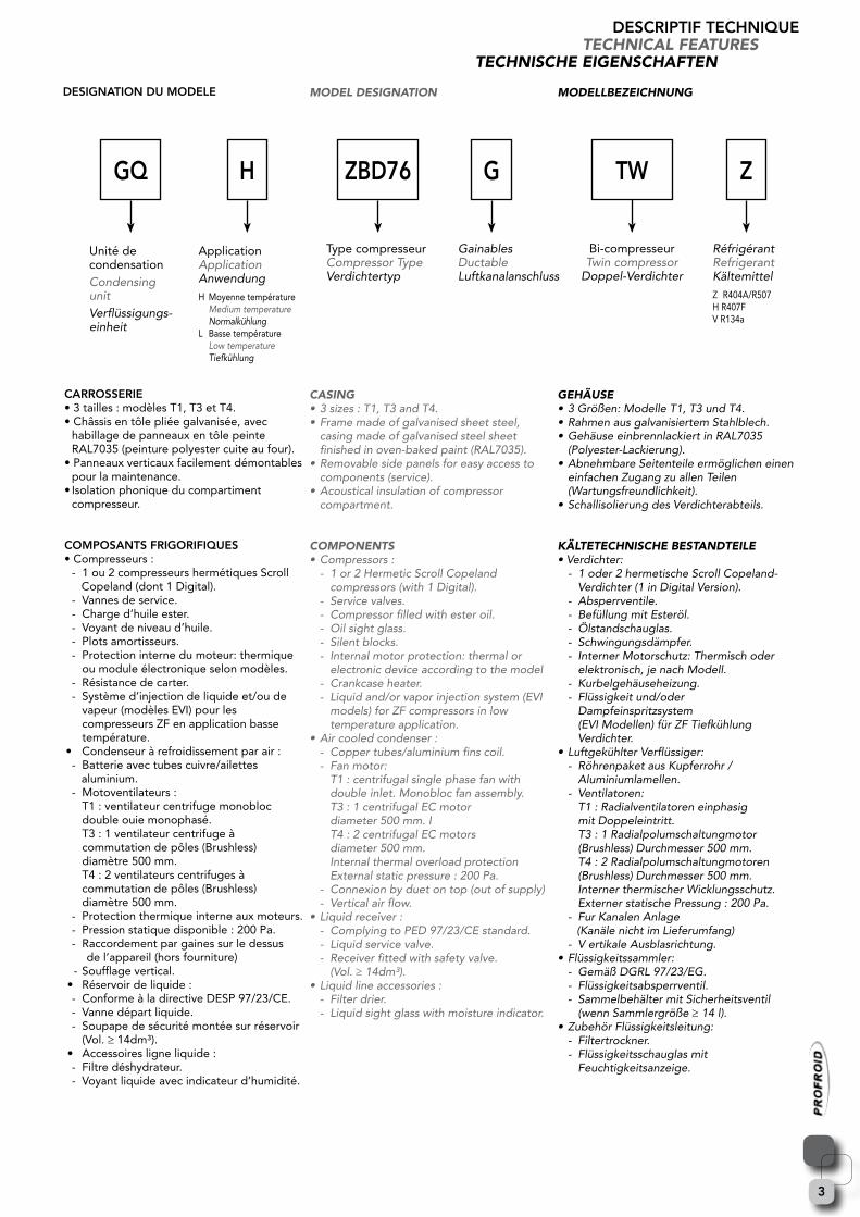
GainablesDuctableLuftkanalanschluss
modellBeZeiChnung
gehÄuse •3Größen:ModelleT1,T3undT4.•RahmenausgalvanisiertemStahlblech.•GehäuseeinbrennlackiertinRAL7035 (Polyester-Lackierung).•AbnehmbareSeitenteileermöglicheneinen einfachen Zugang zu allen Teilen (Wartungsfreundlichkeit).•SchallisolierungdesVerdichterabteils.
KÄlteteChnisChe Bestandteile•Verdichter: - 1oder2hermetischeScrollCopeland- Verdichter(1inDigitalVersion). - Absperrventile. - BefüllungmitEsteröl. - Ölstandschauglas. - Schwingungsdämpfer. - InternerMotorschutz:Thermischoder elektronisch,jenachModell. - Kurbelgehäuseheizung. - Flüssigkeitund/oder Dampfeinspritzsystem (EVIModellen)fürZFTiefkühlung Verdichter.•LuftgekühlterVerflüssiger: - RöhrenpaketausKupferrohr/ Aluminiumlamellen. - Ventilatoren: T1:Radialventilatoreneinphasig mitDoppeleintritt. T3:1Radialpolumschaltungmotor (Brushless)Durchmesser500mm. T4:2Radialpolumschaltungmotoren (Brushless)Durchmesser500mm. InternerthermischerWicklungsschutz. ExternerstatischePressung:200Pa. - FurKanalenAnlage (KanälenichtimLieferumfang) - VertikaleAusblasrichtung.•Flüssigkeitssammler: - GemäßDGRL97/23/EG. -Flüssigkeitsabsperrventil. - SammelbehältermitSicherheitsventil (wennSammlergröße≥14l).•ZubehörFlüssigkeitsleitung: - Filtertrockner. - Flüssigkeitsschauglasmit Feuchtigkeitsanzeige.
dEsIgnaTIOn dU MOdElE
caRROssERIE • 3 tailles : modèles T1, T3 et T4.• Châssis en tôle pliée galvanisée, avec habillage de panneaux en tôle peinte RAL7035 (peinture polyester cuite au four).• Panneaux verticaux facilement démontables pour la maintenance.• Isolation phonique du compartiment compresseur.
cOMpOsanTs fRIgORIfIQUEs• Compresseurs : - 1 ou 2 compresseurs hermétiques Scroll Copeland (dont 1 Digital). - Vannes de service. - Charge d’huile ester. - Voyant de niveau d’huile. - Plots amortisseurs. - Protection interne du moteur: thermique ou module électronique selon modèles. - Résistance de carter. - Système d’injection de liquide et/ou de vapeur (modèles EVI) pour les compresseurs ZF en application basse température.• Condenseur à refroidissement par air : - Batterie avec tubes cuivre/ailettes aluminium. - Motoventilateurs : T1 : ventilateur centrifuge monobloc double ouie monophasé. T3 : 1 ventilateur centrifuge à commutation de pôles (Brushless) diamètre 500 mm. T4 : 2 ventilateurs centrifuges à commutation de pôles (Brushless) diamètre 500 mm. - Protection thermique interne aux moteurs. - Pression statique disponible : 200 Pa. - Raccordement par gaines sur le dessus de l’appareil (hors fourniture) - Soufflage vertical.• Réservoir de liquide : - Conforme à la directive DESP 97/23/CE. - Vanne départ liquide. - Soupape de sécurité montée sur réservoir (Vol. ≥ 14dm³).• Accessoires ligne liquide : - Filtre déshydrateur. - Voyant liquide avec indicateur d’humidité.
dEscRIpTIf TEcHnIQUEteChniCal features
teChnisChe eigensChaften
Z
RéfrigérantRefrigerantKältemittel Z R404A/R507H R407FV R134a
g
Unité de condensation Condensing unitVerflüssigungs-einheit
gQ ZBd76
Type compresseurCompressor TypeVerdichtertyp
ApplicationApplicationAnwendungH Moyenne température Mediumtemperature NormalkühlungL Basse température Low temperature Tiefkühlung
H TW
Bi-compresseurTwin compressor
Doppel-Verdichter
4
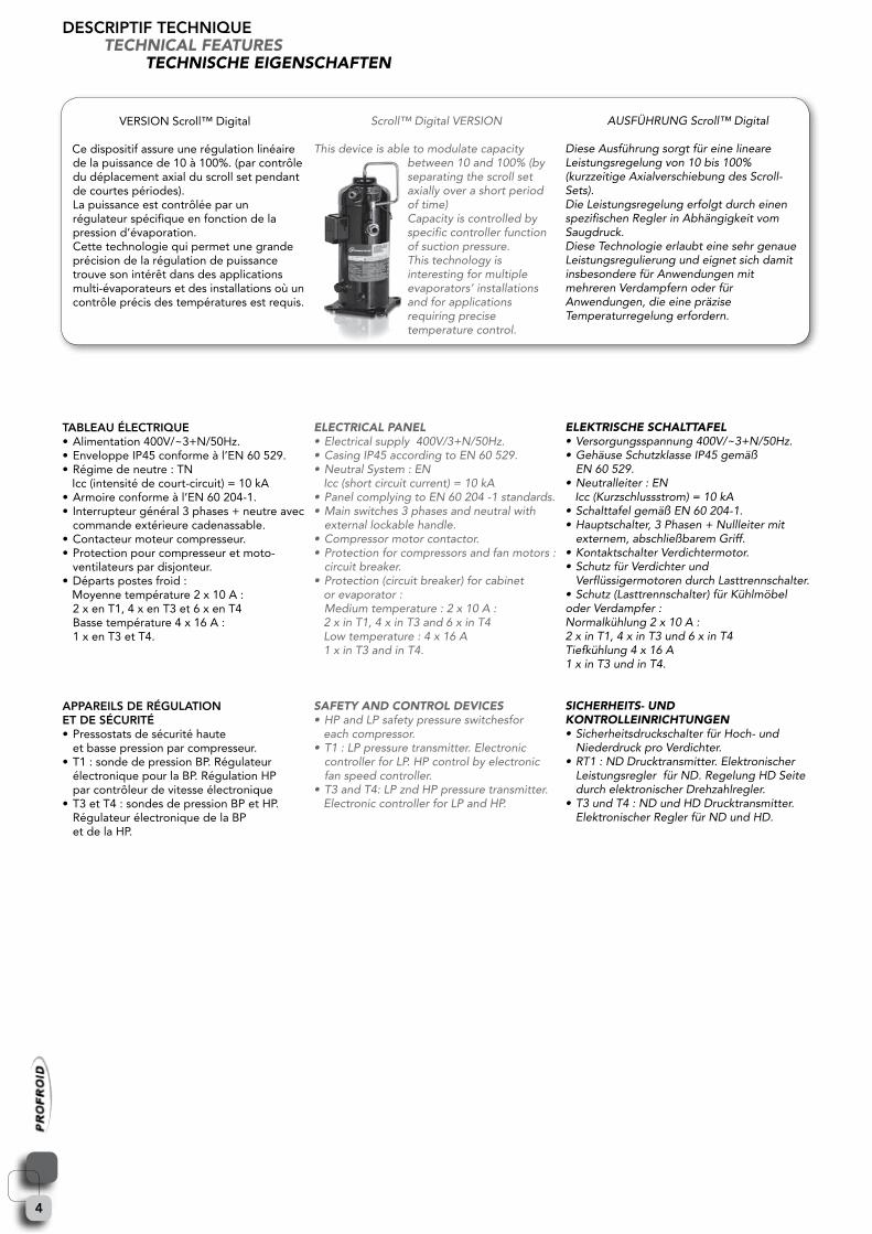
VERSION Scroll™ Digital
Ce dispositif assure une régulation linéaire de la puissance de 10 à 100%. (par contrôle du déplacement axial du scroll set pendant de courtes périodes). La puissance est contrôlée par un régulateur spécifique en fonction de la pression d’évaporation. Cette technologie qui permet une grande précision de la régulation de puissance trouve son intérêt dans des applications multi-évaporateurs et des installations où un contrôle précis des températures est requis.
TaBlEaU ÉlEcTRIQUE• Alimentation 400V/~3+N/50Hz.• Enveloppe IP45 conforme à l’EN 60 529.• Régime de neutre : TN Icc (intensité de court-circuit) = 10 kA• Armoire conforme à l’EN 60 204-1.• Interrupteur général 3 phases + neutre avec commande extérieure cadenassable.• Contacteur moteur compresseur.• Protection pour compresseur et moto- ventilateurs par disjonteur.• Départs postes froid : Moyenne température 2 x 10 A : 2 x en T1, 4 x en T3 et 6 x en T4 Basse température 4 x 16 A : 1 x en T3 et T4.
appaREIls dE RÉgUlaTIOn ET dE sÉcURITÉ• Pressostats de sécurité haute et basse pression par compresseur.• T1 : sonde de pression BP. Régulateur électronique pour la BP. Régulation HP par contrôleur de vitesse électronique• T3 et T4 : sondes de pression BP et HP. Régulateur électronique de la BP et de la HP.
Scroll™DigitalVERSION
Thisdeviceisabletomodulatecapacitybetween10and100%(byseparating the scroll set axiallyoverashortperiod
of time)Capacity is controlled by specific controller function ofsuctionpressure.This technology is interesting for multiple evaporators’installationsand for applications requiringprecisetemperaturecontrol.
eleCtriCal Panel•Electricalsupply400V/3+N/50Hz.•CasingIP45accordingtoEN60529.•NeutralSystem:ENIcc(shortcircuitcurrent)=10kA•PanelcomplyingtoEN60204-1standards.•Mainswitches3phasesandneutralwith externallockablehandle.•Compressormotorcontactor.•Protectionforcompressorsandfanmotors: circuitbreaker.•Protection(circuitbreaker)forcabinet orevaporator: Mediumtemperature:2x10A: 2xinT1,4xinT3and6xinT4Lowtemperature:4x16A 1xinT3andinT4.
safetY and Control deViCes•HPandLPsafetypressureswitchesfor eachcompressor.•T1:LPpressuretransmitter.Electronic controllerforLP.HPcontrolbyelectronic fanspeedcontroller.•T3andT4:LPzndHPpressuretransmitter. ElectroniccontrollerforLPandHP.
AUSFÜHRUNGScroll™Digital
DieseAusführungsorgtfüreinelineareLeistungsregelungvon10bis100%(kurzzeitigeAxialverschiebungdesScroll-Sets).DieLeistungsregelungerfolgtdurcheinenspezifischenReglerinAbhängigkeitvomSaugdruck.DieseTechnologieerlaubteinesehrgenaueLeistungsregulierung und eignet sich damit insbesonderefürAnwendungenmitmehreren Verdampfern oder für Anwendungen,dieeinepräziseTemperaturregelungerfordern.
eleKtrisChe sChalttafel•Versorgungsspannung400V/~3+N/50Hz.•GehäuseSchutzklasseIP45gemäß EN60529.•Neutralleiter:ENIcc(Kurzschlussstrom)=10kA•SchalttafelgemäßEN60204-1.•Hauptschalter,3Phasen+Nullleitermit externem,abschließbaremGriff.•KontaktschalterVerdichtermotor.•SchutzfürVerdichterund VerflüssigermotorendurchLasttrennschalter.•Schutz(Lasttrennschalter)fürKühlmöbeloder Verdampfer :Normalkühlung2x10A: 2xinT1,4xinT3und6xinT4 Tiefkühlung4x16A 1xinT3undinT4.
siCherheits- und KontrolleinriChtungen•SicherheitsdruckschalterfürHoch-und NiederdruckproVerdichter.•RT1:NDDrucktransmitter.Elektronischer LeistungsreglerfürND.RegelungHDSeite durchelektronischerDrehzahlregler.•T3undT4:NDundHDDrucktransmitter. ElektronischerReglerfürNDundHD.
dEscRIpTIf TEcHnIQUEteChniCal features
teChnisChe eigensChaften

5
accEssOIREs OpTIOnnEls • Séparateur d’huile.• Régulateur d’huile électronique avec séparateur sur modèles TWIN.• Electrovanne liquide (livrée séparément).• Commande de chambre à distance par régulateur électronique.• Boîtier de commande à distance protégé contre les intempéries (interrupteur M-A, voyant, 5 m de câble).• Manomètres HP + BP.• HP flottante.
pREcaUTIOns d’InsTallaTIOn• Vérifier la tension d’alimentation du réseau électrique.• Prendre connaissance de la notice de mise en service avant toute intervention.• Ne pas utiliser les compresseurs hors des limites de fonctionnement spécifiées par le constructeur.• Implantation à l’intérieur uniquement.• Le circuit frigorifique doit être parfaitement propre, sec et réalisé selon les règles de l’art.• La surchauffe des gaz aspirés doit être limitée (20K maxi et 10K mini).• Fixer l’unité au sol.• Connecter immédiatement le refoulement d’air par gaines (hors fourniture) • Pour les modèles EVI : le sous refroidissement additionnel devra être pris en compte pour la sélection des détendeurs et il est conseillé d’isoler thermiquement la ligne liquide.
InsTRUcTIOns pOUR lE MOnTagE, la MIsE En sERvIcE, l’UTIlIsaTIOn ET la MaInTEnancERespecter les prescriptions mentionnées dans le guide d’application du constructeur de compresseur et dans la notice d’instructions PROFROID.
cOMplEMEnT d’InfORMaTIOns sUR lEs cOndITIOns d’annOncE dEs caRacTERIsTIQUEs TEcHnIQUEs.(2) Les niveaux de pression acoustique (en dBA à 10 mètres) sont indiqués en champ libre.Le fonctionnement à un régime différent de ces conditions nominales peut conduire à des résultats différents. Les résultats obtenus sur le lieu de l’installation peuvent être différents par rapport aux valeurs du catalogue, du fait de phénomènes de réflexion (présence de mur, etc ...). L’affaiblissement du niveau sonore en fonction de la distance est théorique et les phénomènes de réflexion et de résonnance peuvent modifier le résultat, soit au niveau global pondéré, soit sur certaines fréquences.(3) Intensité max. de fonctionnement du ventilateur, tension d’alimentation : 230V/~1/50Hz. (T1) / 400V/~3/50Hz. (T3 et T4).(4) Intensité de démarrage (courant rotor bloqué) du compresseur, tension d’alimentation : 400V/~3/50Hz.(5) Intensité max. de fonctionnement du compresseur, tension d’alimentation : 400V/~3/50Hz.
oPtional aCCessories•Oilseparator.•Electronicoilregulatorwithseparatorfor TWINmodels.•Liquidsolenoidvalve(separatelydelivered)•Roomcontrolbyremoteelectronic controller.•Waterproofremotecontrolbox(on-off switch,light,5mofcable).•HP+LPmanometers.•FloatingHP.
installation guidanCe•Ensurethattheelectricitysupplytothe installationissuitable.•Readcarefulystart-upandoperating instructionsmanualbeforeanyintervention.•Donotusethecompressorsoutside operating limits specified by the manufacturer.• Installinsideabuildingonly.•Therefrigeratingcircuitmustbeperfectly clean, dry and installed according to best refrigerationpractice.•Suctionsuperheatshouldbelimited (20Kmaxiand10Kmini).•Theunitmustbeholdonground.•Connectedonduet(outofsupply)•ForEVImodels:liquidsubcoolinghas to be taken into account for expansion valvesselectionanditisadvisedtoput thermalinsulationonliquidline.
instruCtions for installation, Commissioning, oPerating and maintenanCeRespect the prescriptions mentioned in compressor manufacturer application guidelinesandPROFROIDoperatinginstructions.
additional information on the Conditions of announCement ofteChniCal data.(2)Thesoundpresurelevels(indB(A)at10meters)arementionedinfreefield.Runningtheequipmentinconditionsdifferingfromthesenominalvaluesmayleadtodifferentresults.The results obtained on the installation site may differ from those in this leaflet, due to soundreflectionsfromwalls,etc.Thereductionofsoundlevelasafunctionofdistance is theoretical and sound reflection and resonance may alter the results, either on totalsoundleveloroncertainfrequencies.(3)LockedRotorcurrentoffan,supply230V/~1/50Hz.(T1) / 400V/~3/50Hz.(T3 and T4).(4)LockedRotorcurrentofcompressor,supply400V/~3/50Hz.(5)Max.operatingcurrentofcompressor,supply400V/~3/50Hz.
ZusatZausstattung auf wunsCh •Ölabscheider.•ElektronischeÖlstandsregulierungmit AbscheiderbeiTWIN-Modellen.•Flüssigkeits-Magnetventil(separatgeliefert).•FerngesteuerteRaumüberwachungmit elektronischerRegelung.•WasserdichteFernsteuerungsbox(Ein-Aus- Schalter,Beleuchtung,5mKabel).•Hoch-undNiederdruckmanometer.•SchwebendeHP.
aufstellhinweise•Versorgungsspannungprüfen.• Inbetriebnahmehandbuchundtechnisches HandbuchvorjedemEingriffander Anlagegenaulesen.•DieVerdichternichtaußerhalbdervom HerstellerfestgelegtenEinsatzgrenzen betreiben.•EinbaunurinnerhalbeinesGebäudes.•DerKältekreislaufmussabsolutsauber, trockenundfachgerechtinstalliertsein.•DieSauggasüberhitzungmussbegrenztsein (20Kmaxiund10Kmini).•DieEinheitamBodenfixieren.•DruckseiteanLuftkanalanschließen(KanälenichtimLieferumfang)•FürEVIModelle:diezusätzliche Unterkühlung sollte berücksichtigt werdenbeiderAuswahldesExpansionsventilsundesistratsamdieFlüssigkeitsleitungzuisolieren.
anweisungen fÜr einBau, inBetrieBnahme, BetrieB und wartungDieHinweisedesVerdichterherstellerslt.HandbuchunddieHinweisedesTechnischenHandbuchsunddesInbetriebnahmehandbuchsvonPROFROIDsindzubeachten.
weitere informationen Zu den angegeBenen teChnisChen daten.(2)DieSchalldruckpegelsindangegebeninFreifeldmessungin10m.DerBetriebunteranderen als den hier genannten NominalbedingungenkannzuunterschiedlichenErgebnissenführen.DieLeistungsdatenamAufstellortkönnensichaufgrundvonSchallreflektionusw.vondenKatalogwertenunterscheiden(Mauern,Wändeetc.).DieVerringerungdesSchalldruckpegels bei zunehmender EntfernungisttheoretischerNaturunddietatsächlichenGegebenheitenvorOrtkönnendieseswg.ReflektionundResonanzbeeinflussen, sei es hinsichtlich des gewichteten Gesamtpegels oder hinsichtlich gewisserFrequenzen.(3)Max.StromstärkeLüfterbetrieb,Versorgungsspannung:230V/~1/50Hz. (T1) / 400V/~3/50Hz. (T3 und T4).(4)Anlaufstromstärke(beiblockiertemRotor)des Verdichters, Versorgungsspannung: 400V/~3/50Hz.(5)Max.BetriebsstromdesVerdichters,Versorungsspannung:400V/~3/50Hz.
dEscRIpTIf TEcHnIQUEteChniCal features
teChnisChe eigensChaften
6
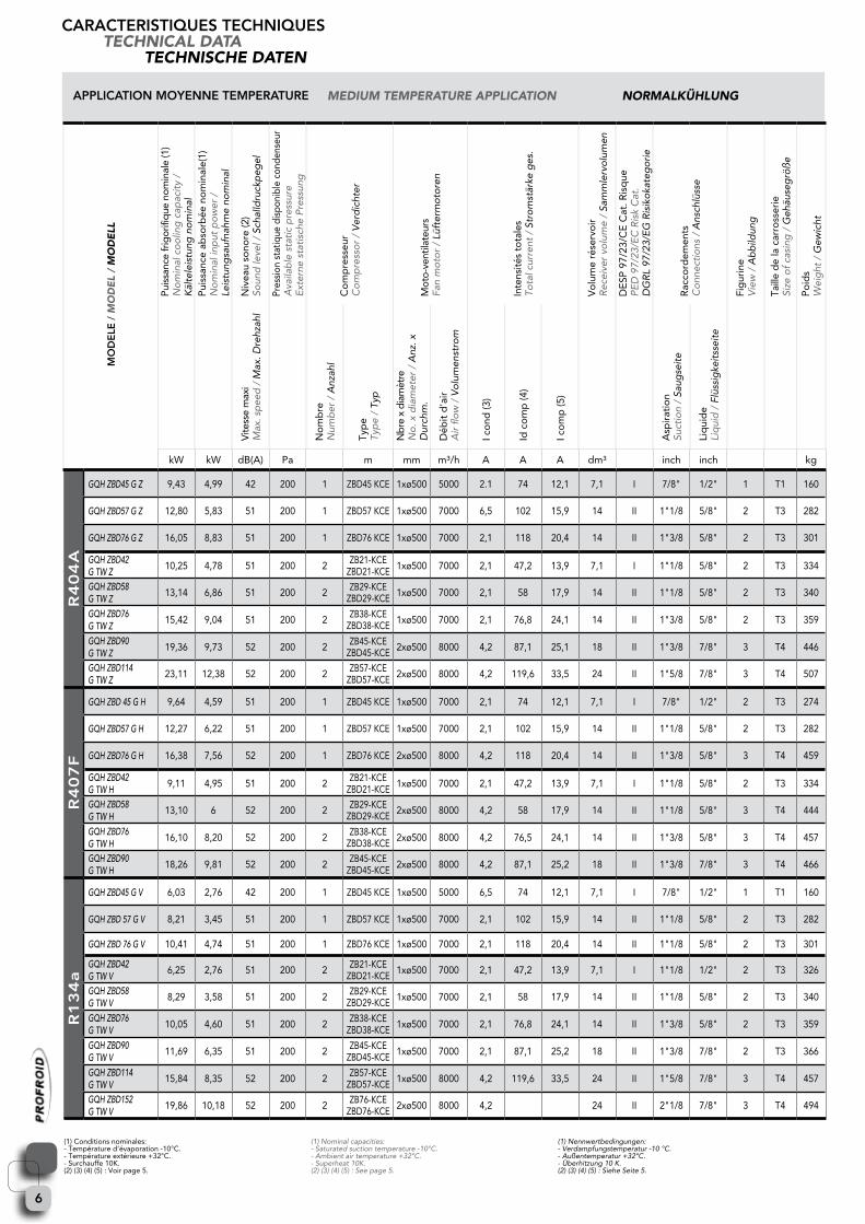
(1) Conditions nominales:- Température d’évaporation -10°C. - Température extérieure +32°C.- Surchauffe 10K.(2) (3) (4) (5) : Voir page 5.
(1)Nominalcapacities:-Saturatedsuctiontemperature-10°C.-Ambientairtemperature+32°C.-Superheat10K.(2)(3)(4)(5):Seepage5.
(1)Nennwertbedingungen:-Verdampfungstemperatur-10°C.-Außentemperatur+32°C.-Überhitzung10K.(2)(3)(4)(5):SieheSeite5.
applIcaTIOn MOYEnnE TEMpERaTURE medium temPerature aPPliCation normalKÜhlung
caRacTERIsTIQUEs TEcHnIQUEsteChniCal data
teChnisChe daten
MO
dE
lE /
mo
de
l /
mo
de
ll
Puis
sanc
e fr
igor
ifiq
ue n
omin
ale
(1)
No
min
alc
oo
ling
cap
acit
y/
K
älte
leis
tung
no
min
alP
uiss
ance
ab
sorb
ée n
om
inal
e(1)
N
om
inal
inp
utp
ow
er/
Le
istu
ngsa
ufna
hme
nom
inal
Niv
eau
sono
re (2
) So
und
leve
l/S
chal
ldru
ckp
egel
Pres
sion
sta
tique
dis
poni
ble
cond
ense
ur
Ava
ilab
les
tati
cp
ress
ure
E
xter
nes
tati
sche
Pre
ssun
g
Co
mp
ress
eur
Co
mp
ress
or
/V
erd
icht
er
Mot
o-ve
ntila
teur
sFa
nm
oto
r/
Lüft
erm
oto
ren
Inte
nsité
s to
tale
sTo
talc
urre
nt/
Str
om
stär
keg
es.
Vo
lum
e ré
serv
oir
Rec
eive
rvo
lum
e/
Sam
mle
rvo
lum
en
DE
SP 9
7/23
/CE
Cat
. Ris
que
PE
D9
7/23
/EC
Ris
kC
at.
DG
RL
97/2
3/E
GR
isik
oka
teg
ori
e
Rac
cord
emen
tsC
onn
ecti
ons
/A
nsch
lüss
e
Fig
urin
eV
iew
/A
bb
ildun
g
Taill
e d
e la
car
ross
erie
Size
of
casi
ng/
Geh
äuse
grö
ße
Po
ids
Wei
ght
/G
ewic
ht
Vite
sse
max
iM
ax.s
pee
d/
Max
.Dre
hzah
l
No
mb
reN
umb
er/
Anz
ahl
Typ
eTy
pe
/Ty
p
Nbr
e x
diam
ètre
No
.xd
iam
eter
/A
nz.x
D
urch
m.
Déb
it d
'air
Air
flo
w/
Vo
lum
enst
rom
I co
nd (3
)
Id c
om
p (4
)
I co
mp
(5)
Asp
irat
ion
Suct
ion
/Sa
ugse
ite
Liq
uid
e Li
qui
d/
Flü
ssig
keit
ssei
te
kW kW dB(A) Pa m mm m³/h A A A dm³ inch inch kg
R4
04
a
GQH ZBD45 G Z 9,43 4,99 42 200 1 ZBD45 KCE 1xø500 5000 2.1 74 12,1 7,1 I 7/8" 1/2" 1 T1 160
GQH ZBD57 G Z 12,80 5,83 51 200 1 ZBD57 KCE 1xø500 7000 6,5 102 15,9 14 II 1"1/8 5/8" 2 T3 282
GQH ZBD76 G Z 16,05 8,83 51 200 1 ZBD76 KCE 1xø500 7000 2,1 118 20,4 14 II 1"3/8 5/8" 2 T3 301
GQH ZBD42 G TW Z
10,25 4,78 51 200 2 ZB21-KCE ZBD21-KCE 1xø500 7000 2,1 47,2 13,9 7,1 I 1"1/8 5/8" 2 T3 334
GQH ZBD58 G TW Z
13,14 6,86 51 200 2 ZB29-KCE ZBD29-KCE 1xø500 7000 2,1 58 17,9 14 II 1"1/8 5/8" 2 T3 340
GQH ZBD76 G TW Z
15,42 9,04 51 200 2 ZB38-KCE ZBD38-KCE 1xø500 7000 2,1 76,8 24,1 14 II 1"3/8 5/8" 2 T3 359
GQH ZBD90 G TW Z
19,36 9,73 52 200 2 ZB45-KCE ZBD45-KCE 2xø500 8000 4,2 87,1 25,1 18 II 1"3/8 7/8" 3 T4 446
GQH ZBD114 G TW Z
23,11 12,38 52 200 2 ZB57-KCE ZBD57-KCE 2xø500 8000 4,2 119,6 33,5 24 II 1"5/8 7/8" 3 T4 507
R4
07
f
GQH ZBD 45 G H 9,64 4,59 51 200 1 ZBD45 KCE 1xø500 7000 2,1 74 12,1 7,1 I 7/8" 1/2" 2 T3 274
GQH ZBD57 G H 12,27 6,22 51 200 1 ZBD57 KCE 1xø500 7000 2,1 102 15,9 14 II 1"1/8 5/8" 2 T3 282
GQH ZBD76 G H 16,38 7,56 52 200 1 ZBD76 KCE 2xø500 8000 4,2 118 20,4 14 II 1"3/8 5/8" 3 T4 459
GQH ZBD42 G TW H
9,11 4,95 51 200 2 ZB21-KCE ZBD21-KCE 1xø500 7000 2,1 47,2 13,9 7,1 I 1"1/8 5/8" 2 T3 334
GQH ZBD58 G TW H
13,10 6 52 200 2 ZB29-KCE ZBD29-KCE 2xø500 8000 4,2 58 17,9 14 II 1"1/8 5/8" 3 T4 444
GQH ZBD76 G TW H
16,10 8,20 52 200 2 ZB38-KCE ZBD38-KCE 2xø500 8000 4,2 76,5 24,1 14 II 1"3/8 5/8" 3 T4 457
GQH ZBD90 G TW H
18,26 9,81 52 200 2 ZB45-KCE ZBD45-KCE 2xø500 8000 4,2 87,1 25,2 18 II 1"3/8 7/8" 3 T4 466
R1
34
a
GQH ZBD45 G V 6,03 2,76 42 200 1 ZBD45 KCE 1xø500 5000 6,5 74 12,1 7,1 I 7/8" 1/2" 1 T1 160
GQH ZBD 57 G V 8,21 3,45 51 200 1 ZBD57 KCE 1xø500 7000 2,1 102 15,9 14 II 1"1/8 5/8" 2 T3 282
GQH ZBD 76 G V 10,41 4,74 51 200 1 ZBD76 KCE 1xø500 7000 2,1 118 20,4 14 II 1"1/8 5/8" 2 T3 301
GQH ZBD42 G TW V
6,25 2,76 51 200 2 ZB21-KCE ZBD21-KCE 1xø500 7000 2,1 47,2 13,9 7,1 I 1"1/8 1/2" 2 T3 326
GQH ZBD58 G TW V
8,29 3,58 51 200 2 ZB29-KCE ZBD29-KCE 1xø500 7000 2,1 58 17,9 14 II 1"1/8 5/8" 2 T3 340
GQH ZBD76 G TW V
10,05 4,60 51 200 2 ZB38-KCE ZBD38-KCE 1xø500 7000 2,1 76,8 24,1 14 II 1"3/8 5/8" 2 T3 359
GQH ZBD90 G TW V
11,69 6,35 51 200 2 ZB45-KCE ZBD45-KCE 1xø500 7000 2,1 87,1 25,2 18 II 1"3/8 7/8" 2 T3 366
GQH ZBD114 G TW V
15,84 8,35 52 200 2 ZB57-KCE ZBD57-KCE 1xø500 8000 4,2 119,6 33,5 24 II 1"5/8 7/8" 3 T4 457
GQH ZBD152 G TW V
19,86 10,18 52 200 2 ZB76-KCE ZBD76-KCE 2xø500 8000 4,2 24 II 2"1/8 7/8" 3 T4 494

7
(1) Conditions nominales :- Température d’évaporation -35°C. - Température extérieure +32°C.- Surchauffe 10K. (2) (3) (4) (5) : Voir page 5.
(1)Nominalcapacitieswith:-Saturatedsuctiontemperature-35°C.-Ambientairtemperature+32°C.-Superheat10K.(2)(3)(4)(5):Seepage5.
(1)Nennwertbedingungen:-Verdampfungstemperatur-35°C.-Außentemperatur+32°C.-Überhitzung10K.(2)(3)(4)(5):SieheSeite5.
caRacTERIsTIQUEs TEcHnIQUEsteChniCal data
teChnisChe daten
applIcaTIOn BassE TEMpERaTURE low temPerature aPPliCation tiefKÜhlungM
Od
ElE
/ m
od
el
/ m
od
ell
Puis
sanc
e fr
igor
ifiq
ue n
omin
ale
(1)
No
min
alc
oo
ling
cap
acit
y/
K
älte
leis
tung
no
min
alP
uiss
ance
ab
sorb
ée n
om
inal
e (1
)N
om
inal
inp
utp
ow
er/
Le
istu
ngsa
ufna
hme
nom
inal
Niv
eau
sono
re (2
) So
und
leve
l/S
chal
ldru
ckp
egel
Pres
sion
sta
tique
dis
poni
ble
cond
ense
ur
Ava
ilab
les
tati
cp
ress
ure
E
xter
nes
tati
sche
Pre
ssun
g
Co
mp
ress
eur
Co
mp
ress
or
/V
erd
icht
er
Mot
o-ve
ntila
teur
sFa
nm
oto
r/
Lüft
erm
oto
ren
Inte
nsité
s to
tale
sTo
talc
urre
nt/
Str
om
stär
keg
es.
Vo
lum
e ré
serv
oir
Rec
eive
rvo
lum
e/
Sam
mle
rvo
lum
en
DE
SP 9
7/23
/CE
Cat
. Ris
que
PE
D9
7/23
/EC
Ris
kC
at.
DG
RL
97/2
3/E
GR
isik
oka
teg
ori
e
Rac
cord
emen
tsC
onn
ecti
ons
/A
nsch
lüss
e
Fig
urin
eV
iew
/A
bb
ildun
g
Taill
e d
e la
car
ross
erie
Size
of
casi
ng/
Geh
äuse
grö
ße
Po
ids
Wei
ght
/G
ewic
ht
Vite
sse
max
iM
ax.s
pee
d/
Max
.Dre
hzah
l
No
mb
reN
umb
er/
Anz
ahl
Typ
eTy
pe
/Ty
p
Nbr
e x
diam
ètre
No
.xd
iam
eter
/A
nz.x
D
urch
m.
Déb
it d
'air
Air
flo
w/
Vo
lum
enst
rom
I co
nd (3
)
Id c
om
p (4
)
I co
mp
(5)
Asp
irat
ion
Suct
ion
/Sa
ugse
ite
Liq
uid
e Li
qui
d/
Flü
ssig
keit
ssei
te
kW kW dB(A) Pa m mm m³/h A A A dm³ inch inch kg
R4
04
a
GQL ZFD18 EVI G Z 5,75 4,06 51 200 1 ZFD18 EVI 1xø500 7000 2,1 74 13,8 14 II 1"1/8 5/8" 2 T3 318
GQL ZFD25 EVI G Z 7 5,36 51 200 1 ZFD25 EVI 1xø500 7000 2,1 102 13,7 14 II 1"1/8 5/8" 2 T3 318
GQL ZFD26 EVI G TW Z
7,48 6,37 51 200 2 ZF13 EVI ZFD13 EVI 1xø500 7000 2,1 73 18 14 II 1"1/8 1/2" 2 T3 353
GQL ZFD36 EVI G TW Z
11,43 8,52 52 200 2 ZF18 EVI ZFD18 EVI 2xø500 8000 4,2 87,8 26,3 18 II 1"3/8 5/8" 3 T4 473
GQL ZFD50 EVI G TW Z
13,84 11,27 52 200 2 ZF25 EVI ZFD25 EVI 2xø500 8000 4,2 115,7 27,4 18 II 1"5/8 7/8" 3 T4 473
R4
07
f
GQL ZFD18 EVI G H 5,03 3,87 51 200 1 ZFD18 EVI 1xø500 7000 2,1 74 13,8 14 II 1"1/8 5/8" 2 T3 318
GQL ZFD25 EVI GH 6,57 4,80 51 200 1 ZFD25 EVI 1xø500 7000 2,1 102 16 14 II 1"1/8 5/8" 2 T3 318
GQL ZFD26 EVI G TW H
6,56 6,18 51 200 2 ZF13 EVI ZFD13 EVI 1xø500 7000 2,1 73 18 14 II 1"1/8 1/2" 2 T3 353
GQL ZFD36 EVI G TW H
9,92 8,18 52 200 2 ZF18 EVI ZFD18 EVI 2xø500 8000 4,2 87,8 26,3 18 II 1"3/8 5/8" 3 T4 473
GQL ZFD50 EVI G TW H
12,92 10,28 52 200 2 ZF25 EVI ZFD25 EVI 2xø500 8000 4,2 115,7 27,4 18 II 1"5/8 7/8" 3 T4 473
8
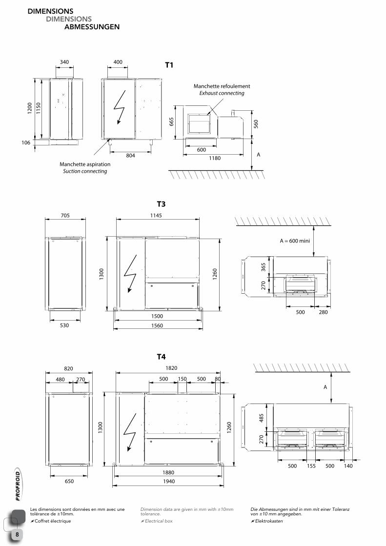
dIMEnsIOnsdIMEnsIOns
aBMEssUngEn
340 400
804 1180
705 1145
530
1300
1260
485
270
820
480 270
650 1940
1880
1500
1560
1820
500
500 155 500 140
150 500 80
500 280
600106
1200
1150
665
365
1260
1300
270
560
A
A = 600 mini
T1
T3
T4
A
Manchette refoulementExhaust connecting
Manchette aspirationSuction connecting
Les dimensions sont données en mm avec une tolérance de ±10mm.
Coffret électrique
Dimensiondataaregiveninmmwith±10mmtolerance.
Electrical box
DieAbmessungensindinmmmiteinerToleranzvon±10mmangegeben.
Elektrokasten
9
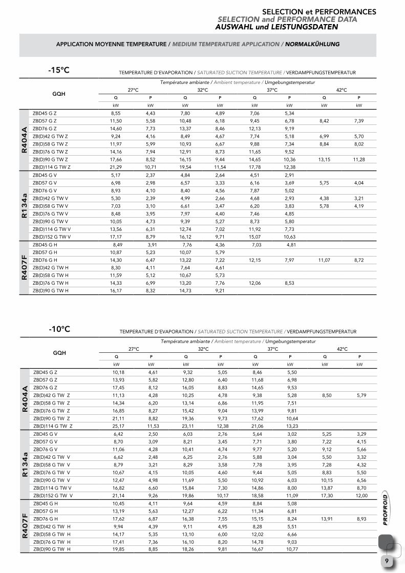
sElEcTIOn et pERfORMancEsseleCtion and PerformanCe data
auswahl und leistungsdaten
-15°c TEMPERATURE D'EVAPORATION / SATURATEDSUCTIONTEMPERATURE/VERDAMPFUNGSTEMPERATUR
gQH
Températureambiante/Ambienttemperature/ Umgebungstemperatur
27°C 32°C 37°C 42°C
Q p Q p Q p Q p
kW kW kW kW kW kW kW kW
R4
04
a
ZBD45 G Z 8,55 4,43 7,80 4,89 7,06 5,34
ZBD57 G Z 11,50 5,58 10,48 6,18 9,45 6,78 8,42 7,39
ZBD76 G Z 14,60 7,73 13,37 8,46 12,13 9,19
ZB(D)42 G TW Z 9,24 4,16 8,49 4,67 7,74 5,18 6,99 5,70
ZB(D)58 G TW Z 11,97 5,99 10,93 6,67 9,88 7,34 8,84 8,02
ZB(D)76 G TW Z 14,16 7,94 12,91 8,73 11,65 9,52
ZB(D)90 G TW Z 17,66 8,52 16,15 9,44 14,65 10,36 13,15 11,28
ZB(D)114 G TW Z 21,29 10,71 19,54 11,54 17,78 12,38
R1
34
a
ZBD45 G V 5,17 2,37 4,84 2,64 4,51 2,91
ZBD57 G V 6,98 2,98 6,57 3,33 6,16 3,69 5,75 4,04
ZBD76 G V 8,93 4,10 8,40 4,56 7,87 5,02
ZB(D)42 G TW V 5,30 2,39 4,99 2,66 4,68 2,93 4,38 3,21
ZB(D)58 G TW V 7,03 3,10 6,61 3,47 6,20 3,83 5,78 4,19
ZB(D)76 G TW V 8,48 3,95 7,97 4,40 7,46 4,85
ZB(D)90 G TW V 10,05 4,73 9,39 5,27 8,73 5,80
ZB(D)114 G TW V 13,56 6,31 12,74 7,02 11,92 7,73
ZB(D)152 G TW V 17,17 8,79 16,12 9,71 15,07 10,63
R4
07
f
ZBD45 G H 8,49 3,91 7,76 4,36 7,03 4,81
ZBD57 G H 10,87 5,23 10,07 5,79
ZBD76 G H 14,30 6,47 13,22 7,22 12,15 7,97 11,07 8,72
ZB(D)42 G TW H 8,30 4,11 7,64 4,61
ZB(D)58 G TW H 11,59 5,12 10,67 5,73
ZB(D)76 G TW H 14,33 6,99 13,20 7,76 12,06 8,53
ZB(D)90 G TW H 16,17 8,32 14,73 9,21
-10°c TEMPERATURE D'EVAPORATION / SATURATEDSUCTIONTEMPERATURE/VERDAMPFUNGSTEMPERATUR
gQH
Températureambiante/Ambienttemperature/ Umgebungstemperatur
27°C 32°C 37°C 42°C
Q p Q p Q p Q p
kW kW kW kW kW kW kW kW
R4
04
a
ZBD45 G Z 10,18 4,61 9,32 5,05 8,46 5,50
ZBD57 G Z 13,93 5,82 12,80 6,40 11,68 6,98
ZBD76 G Z 17,45 8,12 16,05 8,83 14,65 9,53
ZB(D)42 G TW Z 11,13 4,28 10,25 4,78 9,38 5,28 8,50 5,79
ZB(D)58 G TW Z 14,34 6,20 13,14 6,86 11,95 7,51
ZB(D)76 G TW Z 16,85 8,27 15,42 9,04 13,99 9,81
ZB(D)90 G TW Z 21,11 8,82 19,36 9,73 17,62 10,64
ZB(D)114 G TW Z 25,17 11,53 23,11 12,38 21,06 13,23
R1
34
a
ZBD45 G V 6,42 2,50 6,03 2,76 5,64 3,02 5,25 3,29
ZBD57 G V 8,70 3,09 8,21 3,45 7,71 3,80 7,22 4,15
ZBD76 G V 11,06 4,28 10,41 4,74 9,77 5,20 9,12 5,66
ZB(D)42 G TW V 6,62 2,48 6,25 2,76 5,88 3,04 5,50 3,32
ZB(D)58 G TW V 8,79 3,21 8,29 3,58 7,78 3,95 7,28 4,32
ZB(D)76 G TW V 10,67 4,15 10,05 4,60 9,44 5,05 8,83 5,50
ZB(D)90 G TW V 12,47 4,98 11,69 5,50 10,92 6,03 10,15 6,56
ZB(D)114 G TW V 16,82 6,60 15,84 7,30 14,86 8,00 13,87 8,70
ZB(D)152 G TW V 21,14 9,26 19,86 10,17 18,58 11,09 17,30 12,00
R4
07
f
ZBD45 G H 10,45 4,11 9,64 4,59 8,84 5,08
ZBD57 G H 13,19 5,63 12,27 6,22 11,34 6,81
ZBD76 G H 17,62 6,87 16,38 7,55 15,15 8,24 13,91 8,93
ZB(D)42 G TW H 9,94 4,39 9,11 4,95 8,28 5,51
ZB(D)58 G TW H 14,17 5,35 13,10 6,00 12,02 6,66
ZB(D)76 G TW H 17,41 7,36 16,10 8,20 14,78 9,03
ZB(D)90 G TW H 19,85 8,85 18,26 9,81 16,67 10,77
applIcaTIOn MOYEnnE TEMpERaTURE / medium temPerature aPPliCation / normalKÜhlung

10
sElEcTIOn et pERfORMancEsseleCtion and PerformanCe data
auswahl und leistungsdaten
-5°c TEMPERATURE D'EVAPORATION / SATURATEDSUCTIONTEMPERATURE/VERDAMPFUNGSTEMPERATUR
gQH
Températureambiante/Ambienttemperature/ Umgebungstemperatur
27°C 32°C 37°C 42°C
Q p Q p Q p Q p
kW kW kW kW kW kW kW kW
R4
04
a
ZBD45 G Z 11,99 4,79 11,01 5,22 10,04 5,66
ZBD57 G Z 16,55 6,06 15,30 6,61 14,04 7,17
ZBD76 G Z 20,55 8,53 18,96 9,20
ZB(D)42 G TW Z 13,25 4,43 12,24 4,91 11,23 5,40 10,22 5,89
ZB(D)58 G TW Z 16,99 6,42 15,64 7,05 14,29 7,68
ZB(D)76 G TW Z 19,84 8,63 18,22 9,39
ZB(D)90 G TW Z 24,94 9,15 22,96 10,03 20,97 10,91
ZB(D)114 G TW Z 29,40 12,37 27,04 13,22 24,68 14,08
R1
34
a
ZBD45 G V 7,87 2,64 7,42 2,90 6,98 3,16 6,53 3,42
ZBD57 G V 10,67 3,26 10,09 3,61 9,51 3,96 8,93 4,31
ZBD76 G V 13,53 4,53 12,77 4,99 12,01 5,44 11,24 5,89
ZB(D)42 G TW V 8,14 2,59 7,71 2,87 7,27 3,15 6,84 3,42
ZB(D)58 G TW V 10,85 3,36 10,25 3,72 9,65 4,09 9,05 4,46
ZB(D)76 G TW V 13,13 4,36 12,41 4,80 11,69 5,25 10,97 5,69
ZB(D)90 G TW V 15,31 5,25 14,41 5,77 13,51 6,29 12,61 6,81
ZB(D)114 G TW V 20,55 7,00 19,39 7,69 18,24 8,38 17,09 9,08
ZB(D)152 G TW V 25,71 9,87 24,20 10,76 22,70 11,65 21,19 12,54
R4
07
f
ZBD45 G H 12,67 4,32 11,82 4,83 10,97 5,34
ZBD57 G H 15,82 5,96 14,79 6,53 13,75 7,09
ZBD76 G H 21,26 7,36 19,90 8,02 18,53 8,68
ZB(D)42 G TW H 11,98 4,61 11,10 5,18 10,22 5,74
ZB(D)58 G TW H 17,21 5,60 16,06 6,28 14,91 6,96 13,77 7,64
ZB(D)76 G TW H 21,07 7,70 19,65 8,56 18,23 9,41
ZB(D)90 G TW H 24,05 9,41 22,38 10,42 20,70 11,42
0°c TEMPERATURE D'EVAPORATION / SATURATEDSUCTIONTEMPERATURE/VERDAMPFUNGSTEMPERATUR
gQH
Températureambiante/Ambienttemperature/ Umgebungstemperatur
27°C 32°C 37°C 42°C
Q p Q p Q p Q p
kW kW kW kW kW kW kW kW
R4
04
a
ZBD45 G Z 13,97 4,98 12,87 5,40
ZBD57 G Z 19,47 6,32 18,06 6,85 16,66 7,37
ZBD76 G Z 23,89 8,95
ZB(D)42 G TW Z 15,60 4,57 14,45 5,04 13,30 5,52
ZB(D)58 G TW Z 19,92 6,66 18,40 7,27 16,89 7,87
ZB(D)76 G TW Z 23,17 9,03 21,35 9,76
ZB(D)90 G TW Z 29,18 9,48 26,93 10,34 24,67 11,20
ZB(D)114 G TW Z 34,05 13,22 31,37 14,08
R1
34
a
ZBD45 G V 9,53 2,80 9,02 3,06 8,51 3,32
ZBD57 G V 12,93 3,44 12,25 3,79 11,57 4,13 10,89 4,48
ZBD76 G V 16,31 4,82 15,43 5,26 14,55 5,69 13,67 6,13
ZB(D)42 G TW V 9,89 2,72 9,38 2,99 8,87 3,26 8,35 3,54
ZB(D)58 G TW V 13,18 3,51 12,49 3,87 11,79 4,23 11,09 4,60
ZB(D)76 G TW V 15,90 4,59 15,05 5,03 14,20 5,46 13,34 5,90
ZB(D)90 G TW V 18,51 5,58 17,49 6,09 16,47 6,61 15,45 7,12
ZB(D)114 G TW V 24,76 7,44 23,43 8,12 22,09 8,80 20,76 9,48
ZB(D)152 G TW V 30,80 10,54 29,08 11,40 27,36 12,25
R4
07
f
ZBD45 G H 15,12 4,54 14,20 5,05 13,29 5,55
ZBD57 G H 18,67 6,32 17,53 6,88
ZBD76 G H 25,19 7,87 23,75 8,53 22,30 9,19
ZB(D)42 G TW H 14,24 4,84 13,29 5,40 12,34 5,96
ZB(D)58 G TW H 20,57 5,87 19,34 6,54 18,11 7,22
ZB(D)76 G TW H 25,11 8,09 23,57 8,96 22,03 9,83
ZB(D)90 G TW H 28,64 9,97 26,85 10,95
applIcaTIOn MOYEnnE TEMpERaTURE / medium temPerature aPPliCation / normalKÜhlung

11
sElEcTIOn et pERfORMancEsseleCtion and PerformanCe data
auswahl und leistungsdaten
-40°c TEMPERATURE D'EVAPORATION / SATURATEDSUCTIONTEMPERATURE/VERDAMPFUNGSTEMPERATUR
gQl
Températureambiante/Ambienttemperature/ Umgebungstemperatur
27°C 32°C 37°C 42°C
Q p Q p Q p Q p
kW kW kW kW kW kW kW kW
R4
04
a
ZFD18 EVI G Z 4,81 3,38 4,79 3,80 4,78 4,22 4,77 4,64ZFD25 EVI G Z 5,67 4,55 5,54 5,00 5,41 5,45 5,28 5,89ZFD26 EVI G TW Z 6,24 5,33 5,90 6,05 5,56 6,77 5,22 7,49ZFD36 EVI G TW Z 9,60 7,08 9,58 7,94 9,56 8,79 9,54 9,65ZFD50 EVI G TW Z 11,22 9,53 10,95 10,44 10,68 11,35 10,41 12,26
R4
07
f ZFD18 EVI G H 4,16 3,19 4,05 3,66 3,93 4,14ZFD25 EVI G H 5,39 3,99 5,22 4,55 5,06 5,11ZFD26 EVI G TW H 5,28 5,07 4,93 5,88 4,58 6,69ZFD36 EVI G TW H 8,23 6,75 8,00 7,71 7,77 8,68ZFD50 EVI G TW H 10,61 8,55 10,27 9,68 9,93 10,82
-35°c TEMPERATURE D'EVAPORATION / SATURATEDSUCTIONTEMPERATURE/VERDAMPFUNGSTEMPERATUR
gQl
Températureambiante/Ambienttemperature/ Umgebungstemperatur
27°C 32°C 37°C 42°C
Q p Q p Q p Q p
kW kW kW kW kW kW kW kW
R4
04
a
ZFD18 EVI G Z 5,83 3,62 5,75 4,06 5,67 4,49 5,60 4,93ZFD25 EVI G Z 7,14 4,88 7,00 5,36 6,86 5,83 6,71 6,31ZFD26 EVI G TW Z 7,85 5,65 7,48 6,37 7,12 7,10 6,75 7,82ZFD36 EVI G TW Z 11,59 7,63 11,43 8,52 11,27 9,41 11,11 10,30ZFD50 EVI TWIN Z 14,13 10,30 13,84 11,27 13,54 12,24 13,25 13,21
R4
07
f ZFD18 EVI G H 5,19 3,39 5,03 3,87 4,88 4,34ZFD25 EVI G H 6,75 4,24 6,57 4,80 6,39 5,36ZFD26 EVI G TW H 6,90 5,38 6,56 6,18 6,23 6,99ZFD36 EVI G TW H 10,24 7,22 9,92 8,18 9,60 9,15ZFD50 EVI G TW H 13,29 9,14 12,92 10,28
-30°c TEMPERATURE D'EVAPORATION / SATURATEDSUCTIONTEMPERATURE/VERDAMPFUNGSTEMPERATUR
gQl
Températureambiante/Ambienttemperature/ Umgebungstemperatur
27°C 32°C 37°C 42°C
Q p Q p Q p Q p
kW kW kW kW kW kW kW kW
R4
04
a
ZFD18 EVI G Z 7,01 3,86 6,87 4,32 6,72 4,77 6,58 5,23ZFD25 EVI G Z 8,73 5,21 8,56 5,71 8,38 6,21 8,21 6,71ZFD26 EVI G TW Z 9,66 6,01 9,26 6,73 8,86 7,45 8,45 8,16ZFD36 EVI G TW Z 13,88 8,19 13,58 9,12 13,29 10,04 12,99 10,97ZFD50 EVI G TW Z 17,24 11,08 16,88 12,10 16,53 13,12
R4
07
f ZFD18 EVI G H 6,42 3,62 6,22 4,10 6,02 4,57ZFD25 EVI G H 8,35 4,54 8,13 5,10 7,90 5,66ZFD26 EVI G TW H 8,80 5,73 8,45 6,53 8,09 7,33ZFD36 EVI G TW H 12,62 7,75 12,22 8,72 11,81 9,68ZFD50 EVI G TW H 16,39 9,84 15,94 10,98
-25°c TEMPERATURE D'EVAPORATION / SATURATEDSUCTIONTEMPERATURE/VERDAMPFUNGSTEMPERATUR
gQl
Températureambiante/Ambienttemperature/ Umgebungstemperatur
27°C 32°C 37°C 42°C
Q p Q p Q p Q p
kW kW kW kW kW kW kW kW
R4
04
a
ZFD18 EVI G Z 8,36 4,11 8,15 4,58 7,95 5,05 7,74 5,52ZFD25 EVI G Z 10,48 5,55 10,25 6,07 10,03 6,59 9,81 7,11ZFD26 EVI G TW Z 11,66 6,39 11,21 7,11 10,77 7,83ZFD36 EVI G TW Z 16,48 8,77 16,06 9,72 15,64 10,67ZFD50 EVI G TW Z 20,61 11,88 20,16 12,94 19,71 14,00
R4
07
f ZFD18 EVI G H 7,86 3,88 7,61 4,35 7,36 4,83ZFD25 EVI G H 10,13 4,87 9,87 5,43 9,60 5,99ZFD26 EVI G TW H 10,95 6,14 10,56 6,93ZFD36 EVI G TW H 15,41 8,35 14,91 9,32ZFD50 EVI G TW H 19,84 10,63 19,30 11,76
applIcaTIOn BassE TEMpERaTURE / low temPerature aPPliCation / tiefKÜhlung

12
178, rue du Fauge - Z.I. Les Paluds - BP 1152 13782 Aubagne Cedex - France - Site Internet : www.profroid.comTél. +33 4 42 18 05 00 - Fax +33 4 42 18 05 02 - Fax Export : +33 4 42 18 05 09
Le fabricant se réserve le droit de procéder à toutes modification sans préavis.L’image montrée en page de couverture est uniquement à titre indicatif et n’est pas contractuelle
Manufacturerreservestherighttochangeanyproductspecificationswithoutnotice.Thecoverphotoissolelyforillustrationpurposesandnotcontractuallybinding.
Englishversionisatranslationofthefrenchoriginalversionwhichprevailsinallcases.
DerHerstellerbehältsichdasRechtzukurzfristigenÄnderungenvor.DieAbbildungaufderTitelseiteistunverbindlichunddientlediglichderallgemeinenInformation.
_PFI_ 6140Doc. Réf : DQ_QUIETOR CITY