
Presentation Show Micro - CAP’TRONIC · propagation speed v yields the distance between the ......
15
1 page: dp-Consulting Geo Loc Consulting Dominique Paret © 2013 - toute reproduction, même partielle est interdite Jessica Cap’tronic 2013 localisation indoor Techniques…sss Consulting Dominique Paret © 2013 - toute reproduction, même partielle est interdite Jessica Cap’tronic 2013 localisation indoor Techniques…sss - Trilateration - Triangulation - Time Of Arrival - TOA - Time Difference Of Arrival - TDOA - Angle of arrival - Phase shift - RSSI - Fingerprints - etc., etc., etc.
Transcript of Presentation Show Micro - CAP’TRONIC · propagation speed v yields the distance between the ......
1page:dp-Consulting
Geo Loc
Consulting
Dominique Paret
© 2013 - toute reproduction, même partielle est interdite
Jessica Cap’tronic 2013
localisation indoorTechniques…sss
Consulting
Dominique Paret
© 2013 - toute reproduction, même partielle est interdite
Jessica Cap’tronic 2013
localisation indoorTechniques…sss
- Trilateration
- Triangulation
- Time Of Arrival - TOA
- Time Difference Of Arrival - TDOA
- Angle of arrival
- Phase shift
- RSSI
- Fingerprints
- etc., etc., etc.
2page:dp-Consulting
Geo Loc
Consulting
Dominique Paret
© 2013 - toute reproduction, même partielle est interdite
Jessica Cap’tronic 2013
Trilatération.
Trilateration requires the measurement of distancesbetween the mobile unit and the reference units.
This can be achieved by measuring either of the following:
- Triangulation
- Time of flight (TOF)
- Phase shift
- Signal strength(RSSI)
1.4.2 Time of arrival measurements.
In order to obtain the range between two units m and p, beacon signals are transmitted between these devices. Typically, for time of flight range measurements a clock is needed on both units. If these clocks are synchronized, and if the time of emission of the beacon signal is known, then from the time of arrival (TOA) the time of flight (TOF) tpm can be determined. Multiplying by the signal propagation speed v yields the distance between the objects, lpm. In many applications one of the objects is not equipped with an appropriate clock at all, or the clocks are not synchronized. In this case, the distance lpm between the two units can be determined by sending a beacon signal from m to p and measuring the roundtrip time ∆tpm = 2 tpm + tr, given that the signal is reflected by object p:
The beacon signal may be passively (reflection at surface) or actively (retransmission) reflected. The passive reflection technique is well known as RADAR (radio detection and ranging), which is used in large scale outdoor environments. When optical radiation or acoustic waves are used, the terms LIDAR and SONAR (light detection and ranging / sound navigation and ranging), respectively, are applied. Passive reflection indoors is not feasible for most signal technologies (e.g. RF) because of the high degree of multipath occurrences (i.e., echos due to signal reflection at walls and objects). For an active reflection, a beacon retransmission latency tr must be considered. In the passive case tr = 0 holds. If active beacons are deployed in the area, commonly the one-way measurement approach is applied, i.e. the units must be synchronized. In case of radio signals, synchronization of the clocks is critical. Due to the high propagation speed, even a small
Consulting
Dominique Paret
© 2013 - toute reproduction, même partielle est interdite
Jessica Cap’tronic 2013
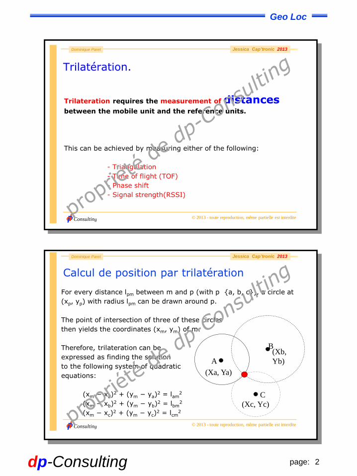
Calcul de position par trilatération
A
B
C
(Xa, Ya)
(Xc, Yc)
(Xb,
Yb)
For every distance lpm between m and p (with p {a, b, c}), a circle at
(xp, yp) with radius lpm can be drawn around p.
The point of intersection of three of these circles
then yields the coordinates (xm, ym) of m.
Therefore, trilateration can be
expressed as finding the solution
to the following system of quadratic
equations:
(xm − xa)2 + (ym − ya)
2 = lam2
(xm − xb)2 + (ym − yb)
2 = lbm2
(xm − xc)2 + (ym − yc)
2 = lcm2
3page:dp-Consulting
Geo Loc
Consulting
Dominique Paret
© 2013 - toute reproduction, même partielle est interdite
Jessica Cap’tronic 2013
Triangulation
Localization based on trilateration implies that participants must be
able to measure distances (or distance differences) between each
other.
Triangulation works in a similar manner, but instead of
distances, angles are measured.
In fact, it can be shown that triangulation can be transformed to
trilateration by simple means (trigonomtry).
Consulting
Dominique Paret
© 2013 - toute reproduction, même partielle est interdite
Jessica Cap’tronic 2013
Triangulation
Two cases can be distinguished ...
- a) The mobile unit measures angles towards signals emitted by
fixed reference units. The collected data yield position and orientation.
and / or
- b) Reference units measure angles towards the signal emitted
by the mobile unit.
Only a location estimate, but not the orientation of the mobile target,
can be obtained.
4page:dp-Consulting
Geo Loc
Consulting
Dominique Paret
© 2013 - toute reproduction, même partielle est interdite
Jessica Cap’tronic 2013
Les balises et le point forment un triangle ;
on connaît deux sommets S1 et S2 des balises de coordonnées
(x1,y1,z1) et (x2,y2,z2), et la longueur D entre les balises. Le troisième
point est donc dans l’espace sur une surface vérifiant
soit
qui est l'équation d'un hyperboloïde.
Consulting
Dominique Paret
© 2013 - toute reproduction, même partielle est interdite
Jessica Cap’tronic 2013
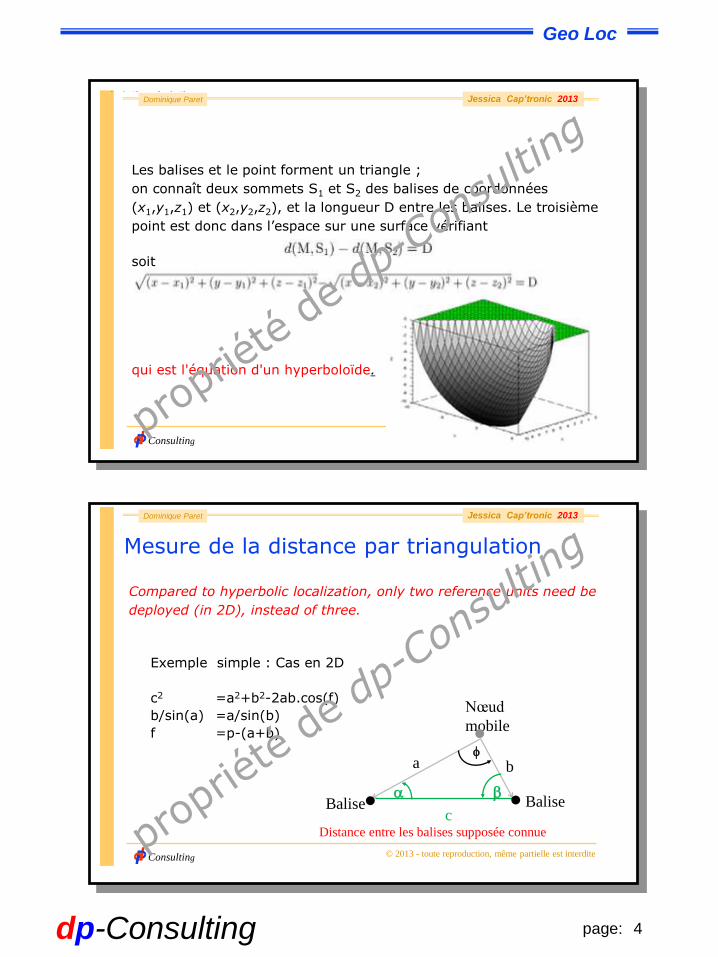
Mesure de la distance par triangulation
Compared to hyperbolic localization, only two reference units need be
deployed (in 2D), instead of three.
Exemple simple : Cas en 2D
c2 =a2+b2-2ab.cos(f)
b/sin(a) =a/sin(b)
f =p-(a+b)
Nœud
mobile•
c
a bf
a b
Distance entre les balises supposée connue
• • BaliseBalise
5page:dp-Consulting
Geo Loc
Consulting
Dominique Paret
© 2013 - toute reproduction, même partielle est interdite
Jessica Cap’tronic 2013
Time of Arrival measurements (ToA)
To obtain the distance between two units m and p, beacon signals are
transmitted between these devices.
For time of flight range measurements a clock is needed on both units.
If these clocks are synchronized, and if the time of emission of the
beacon signal is known, then from the time of arrival (TOA) the time of
flight (TOF) tpm can be determined.
Multiplying by the signal propagation speed v yields the distance
between the objects, lpm.
L = v t !!!
Consulting
Dominique Paret
© 2013 - toute reproduction, même partielle est interdite
Jessica Cap’tronic 2013
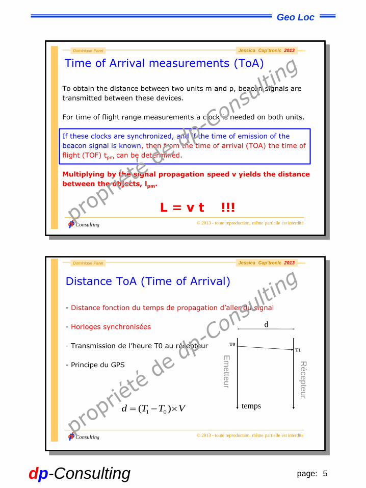
Distance ToA (Time of Arrival)
- Distance fonction du temps de propagation d’aller du signal
- Horloges synchronisées
- Transmission de l’heure T0 au récepteur
- Principe du GPS
Em
ette
ur
Ré
ce
pte
ur
T0
T1
VTTd )( 01temps
d
6page:dp-Consulting
Geo Loc
Consulting
Dominique Paret
© 2013 - toute reproduction, même partielle est interdite
Jessica Cap’tronic 2013
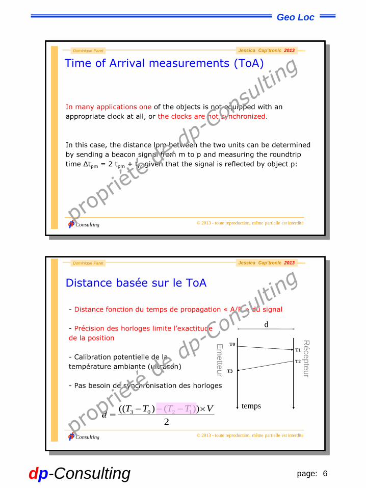
Time of Arrival measurements (ToA)
In many applications one of the objects is not equipped with an
appropriate clock at all, or the clocks are not synchronized.
In this case, the distance lpm between the two units can be determined
by sending a beacon signal from m to p and measuring the roundtrip
time ∆tpm = 2 tpm + tr, given that the signal is reflected by object p:
Consulting
Dominique Paret
© 2013 - toute reproduction, même partielle est interdite
Jessica Cap’tronic 2013
Distance basée sur le ToA
- Distance fonction du temps de propagation « A/R » du signal
- Précision des horloges limite l’exactitude
de la position
- Calibration potentielle de la
température ambiante (ultrason)
- Pas besoin de synchronisation des horloges
Em
ette
ur
Ré
ce
pte
ur
T0
T3
T1
T2
2
))()(( 1203 VTTTTd
temps
d
7page:dp-Consulting
Geo Loc
Consulting
Dominique Paret
© 2013 - toute reproduction, même partielle est interdite
Jessica Cap’tronic 2013
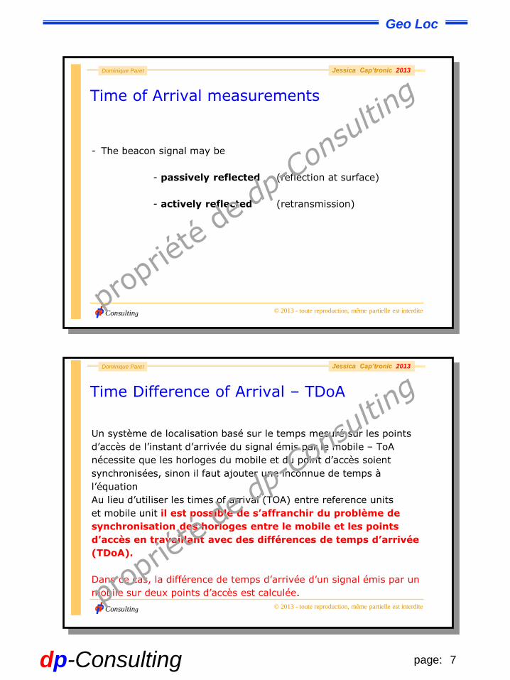
Time of Arrival measurements
- The beacon signal may be
- passively reflected (reflection at surface)
- actively reflected (retransmission)
2.4.3 Phase shift.
The time of flight between two objects p and q can also be determined using a continuous periodic signal, e.g. a (periodically) modulated RF carrier. The signal generated and transmitted by unit p is after the time of flight received by unit q. Internally, unit q generates the same signal and performs a cross correlation between the internal and the received signal. If the units are perfectly synchronized, i.e. the signals are generated concurrently, the result of this operation yields the phase difference _ of the two signals. This phase difference is proportional to the distance between the two objects, d. The distance can then be computed as : , where v is the signal propagation speed and T the signal period. To avoid any ambiguities, must hold.
If the signal is passively reflected by an object, no synchronization is required, and the roundtrip time can be measured. This type of roundtrip time measurement is often used with mobile robots. These robots scan their environment for obstacles using rotating infrared laser beams or ultrasonic waves. The modulated emitted signal is autocorrelated with the reflected received signal. The time of flight corresponds to the phase shift of the modulation signal.
Consulting
Dominique Paret
© 2013 - toute reproduction, même partielle est interdite
Jessica Cap’tronic 2013
Time Difference of Arrival – TDoA
Un système de localisation basé sur le temps mesuré sur les points
d’accès de l’instant d’arrivée du signal émis par le mobile – ToA
nécessite que les horloges du mobile et du point d’accès soient
synchronisées, sinon il faut ajouter une inconnue de temps à
l’équation
Au lieu d’utiliser les times of arrival (TOA) entre reference units
et mobile unit il est possible de s’affranchir du problème de
synchronisation des horloges entre le mobile et les points
d’accès en travaillant avec des différences de temps d’arrivée
(TDoA).
Dans ce cas, la différence de temps d’arrivée d’un signal émis par un
mobile sur deux points d’accès est calculée.
8page:dp-Consulting
Geo Loc
Consulting
Dominique Paret
© 2013 - toute reproduction, même partielle est interdite
Jessica Cap’tronic 2013
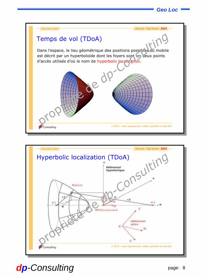
Temps de vol (TDoA)
Dans l’espace, le lieu géométrique des positions possibles du mobile
est décrit par un hyperboloïde dont les foyers sont les deux points
d’accès utilisés d’où le nom de hyperbolic localization.
Consulting
Dominique Paret
© 2013 - toute reproduction, même partielle est interdite
Jessica Cap’tronic 2013
Hyperbolic localization (TDoA)
9page:dp-Consulting
Geo Loc
Consulting
Dominique Paret
© 2013 - toute reproduction, même partielle est interdite
Jessica Cap’tronic 2013
Temps de vol (TDoA)
Trois mesures de TDoA, résultant de la réception simultanée du signal
sur trois points d’accès distincts, sont nécessaires pour calculer la
position du mobile.
Etant donné la complexité de l’environnement construit, seule une
très forte densité de points d’accès, permet d’envisager une telle
configuration.
L’enregistrement des mesures de TDOA est ensuite fait en continu.
Consulting
Dominique Paret
© 2013 - toute reproduction, même partielle est interdite
Jessica Cap’tronic 2013
Angle d’incidence (Angle of Arrival – AoA)
Cette localisation - basée sur les angles d’incidence - mesure
l’angle entre la direction de propagation du rayonnement
électromagnétique incident et la normale aux dioptres des
points d’accès, … le tout à l’aide de rangées d’antennes spécifiques.
Le fait que la propagation des signaux UWB soit plus robuste face aux trajets
multiples, (emploi d’une très large bande), est plutôt un désavantage dans ce
cas. Il est difficile de déterminer avec précision, l’angle d’incidence dans un
ensemble de signaux réfléchis. Ce procédé reste pourtant souvent utilisé dans
les systèmes de localisation UWB car il requiert moins de points d’accès pour
localiser un mobile. Deux références suffisent pour calculer un point dans un
espace plan.
10page:dp-Consulting
Geo Loc
Consulting
Dominique Paret
© 2013 - toute reproduction, même partielle est interdite
Jessica Cap’tronic 2013
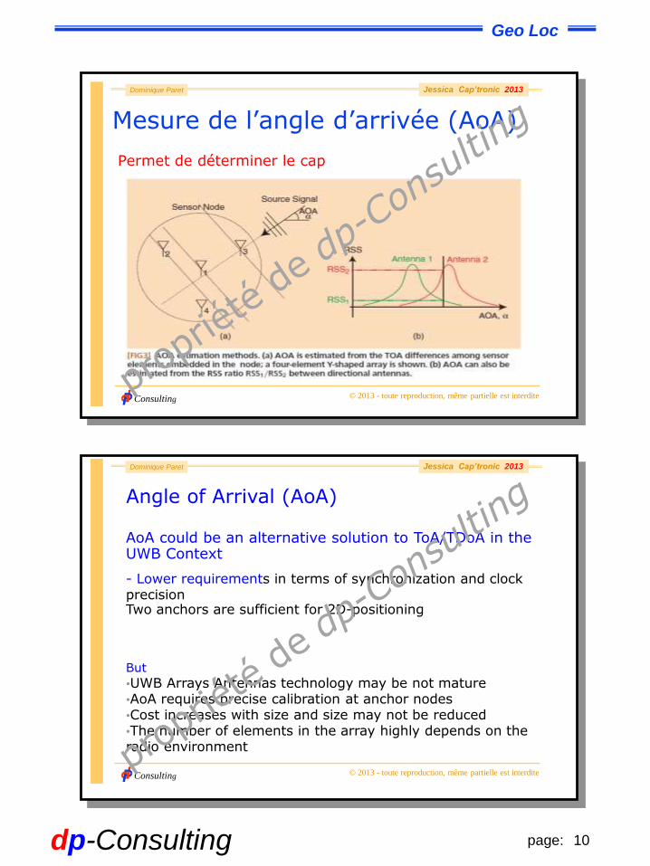
Mesure de l’angle d’arrivée (AoA)
Permet de déterminer le cap
Consulting
Dominique Paret
© 2013 - toute reproduction, même partielle est interdite
Jessica Cap’tronic 2013
AoA could be an alternative solution to ToA/TDoA in the UWB Context
- Lower requirements in terms of synchronization and clock precisionTwo anchors are sufficient for 2D-positioning
But
•UWB Arrays Antennas technology may be not mature•AoA requires precise calibration at anchor nodes•Cost increases with size and size may not be reduced•The number of elements in the array highly depends on the radio environment
Angle of Arrival (AoA)
11page:dp-Consulting
Geo Loc
Consulting
Dominique Paret
© 2013 - toute reproduction, même partielle est interdite
Jessica Cap’tronic 2013
Phase shift
The time of flight corresponds to the phase shift of the
modulation signal.
If the signal is passively reflected by an object, no synchronization is
required, and the roundtrip time can be measured.
This type of roundtrip time measurement is often used with mobile robots.
These robots scan their environment for obstacles using rotating infrared
laser beams or ultrasonic waves. The modulated emitted signal is auto-
correlated with the reflected received signal.
Consulting
Dominique Paret
© 2013 - toute reproduction, même partielle est interdite
Jessica Cap’tronic 2013
Received signal strength (RSS).
A common ranging approach that goes without intricate clock
synchronization is based on signal attenuation.
Range is deduced from the received signal strength (RSS) ....
However, indoor RF (propagation) signal strength is
- non-linear with distance (.... Friis equation .... 1/r²)
- covered with non-Gaussian noise as a result of multipath effects
- environmental effects such as building geometry and traffic.
1.4.5 Hyperbolic localization.
12page:dp-Consulting
Geo Loc
Consulting
Dominique Paret
© 2013 - toute reproduction, même partielle est interdite
Jessica Cap’tronic 2013
Distance fonction du RSSI
Le RSSI est calculé à partir d’indications imprécises de la puissance du signal reçu
Détection d’énergie (ED: Energy Detection)
L'ED peut être utilisée par la couche réseau afin de choisir un canal de transmission
C'est une estimation de la puissance du signal reçu
LQI (Link Quality Indication)
Puissance et/ou la qualité du paquet reçuCette mesure peut être implémentée en utilisant l’ED ou une estimation du ratio signal sur bruit ou bien une combinaison des deux.
Consulting
Dominique Paret
© 2013 - toute reproduction, même partielle est interdite
Jessica Cap’tronic 2013
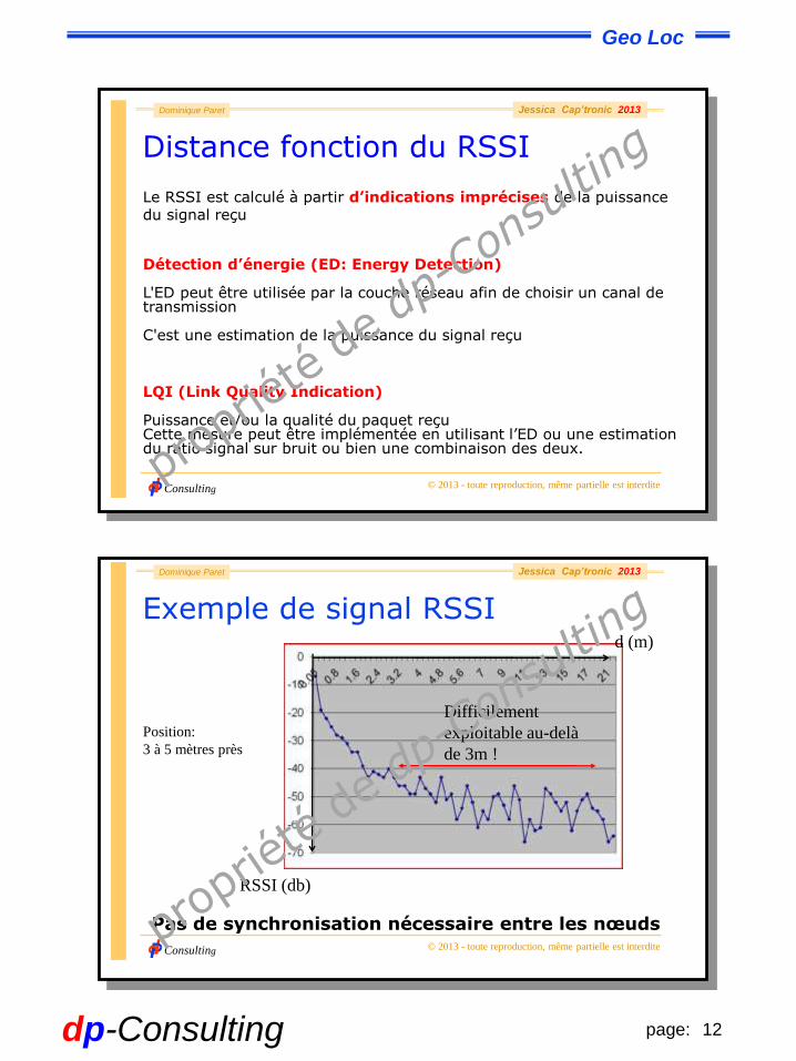
Exemple de signal RSSI
Difficilement
exploitable au-delà
de 3m !
d (m)
RSSI (db)
Pas de synchronisation nécessaire entre les nœuds
Position:
3 à 5 mètres près
13page:dp-Consulting
Geo Loc
Consulting
Dominique Paret
© 2013 - toute reproduction, même partielle est interdite
Jessica Cap’tronic 2013
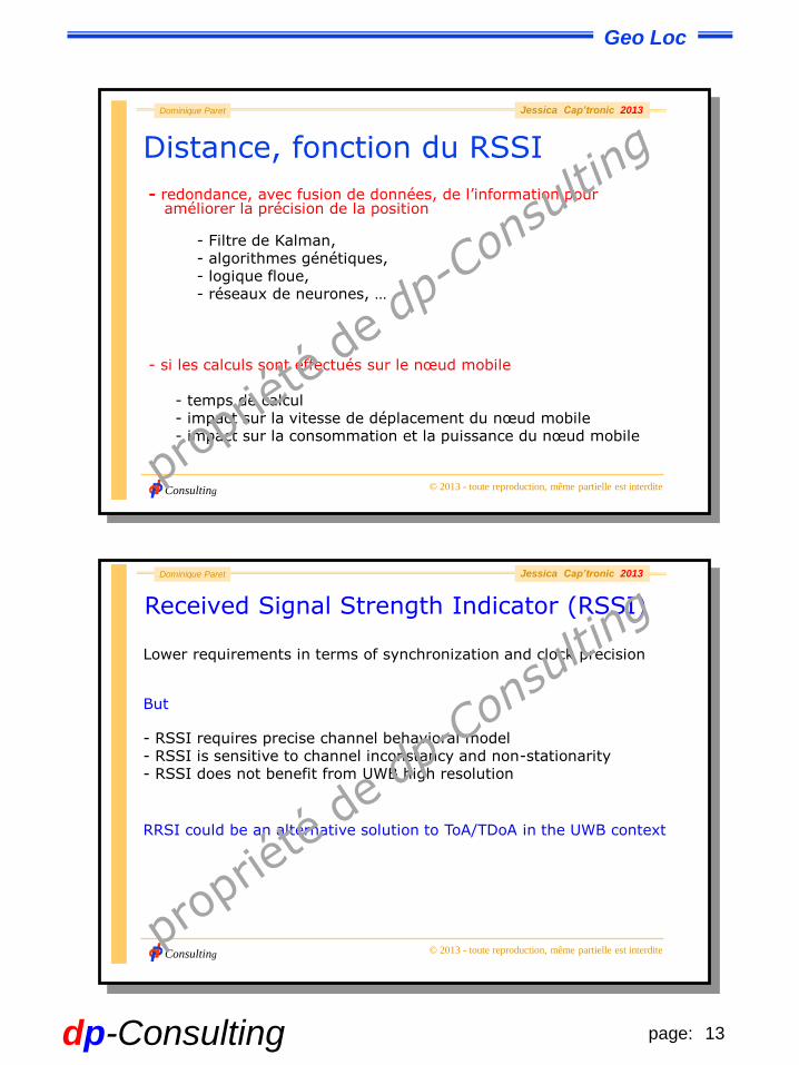
Distance, fonction du RSSI
- redondance, avec fusion de données, de l’information pour améliorer la précision de la position
- Filtre de Kalman, - algorithmes génétiques, - logique floue, - réseaux de neurones, …
- si les calculs sont effectués sur le nœud mobile
- temps de calcul- impact sur la vitesse de déplacement du nœud mobile- impact sur la consommation et la puissance du nœud mobile
Consulting
Dominique Paret
© 2013 - toute reproduction, même partielle est interdite
Jessica Cap’tronic 2013
Received Signal Strength Indicator (RSSI)
Lower requirements in terms of synchronization and clock precision
But
- RSSI requires precise channel behavioral model- RSSI is sensitive to channel inconstancy and non-stationarity- RSSI does not benefit from UWB high resolution
RRSI could be an alternative solution to ToA/TDoA in the UWB context

14page:dp-Consulting
Geo Loc
Consulting
Dominique Paret
© 2013 - toute reproduction, même partielle est interdite
Jessica Cap’tronic 2013
Géolocalisation par empreintes
- Les puissances des signaux émis par les balises sont mesurées à
des points précis (avec redondance des mesures)
- Enregistrement des données mesurées dans une BDD (Banque de
données)
Consulting
Dominique Paret
© 2013 - toute reproduction, même partielle est interdite
Jessica Cap’tronic 2013
Géolocalisation par empreintes
- Les puissances des signaux émis ou reçus par le
nœud mobile sont comparées avec la BDD
- Plus le nombre de points de référence est grand, meilleur est le
positionnement
- Cela suppose un environnement stable pour que les empreintes
soient significatives
Positionnement: exactitude de l’ordre de 1m
15page:dp-Consulting
Geo Loc
Consulting
Dominique Paret
© 2013 - toute reproduction, même partielle est interdite
Jessica Cap’tronic 2013
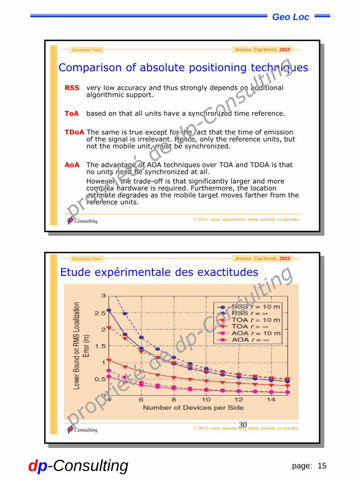
Comparison of absolute positioning techniques
RSS very low accuracy and thus strongly depends on additional algorithmic support.
ToA based on that all units have a synchronized time reference.
TDoA The same is true except for the fact that the time of emission of the signal is irrelevant. Hence, only the reference units, but not the mobile unit, must be synchronized.
AoA The advantage of AOA techniques over TOA and TDOA is that no units need be synchronized at all.
However, the trade-off is that significantly larger and more complex hardware is required. Furthermore, the location estimate degrades as the mobile target moves farther from the reference units.
Consulting
Dominique Paret
© 2013 - toute reproduction, même partielle est interdite
Jessica Cap’tronic 2013
30
Etude expérimentale des exactitudes