
OFFICIAL PORTFOLIO_Brianna Steckler
20
Landscape Architecture Portfolio Brianna Marie Steckler
-
Upload
brianna-steckler -
Category
Documents
-
view
71 -
download
0
Transcript of OFFICIAL PORTFOLIO_Brianna Steckler

Landscape Architecture Portfolio
Brianna Marie Steckler

About the Designer
Brianna Marie Steckler
IwasbornandraisedaroundtheSeattlearea.IgrewupinRedmond,WashingtonwhereIgraduatedfromRedmondHighSchoolin2012.Inthefallof2012IstartedattendingtheUniversityofIdaho.Ihadorginallybegunmycollegecareerworkingtowardsamajorinpsychologyandsociology,butsoonrealizedthiswasnotmypassion.TostaytruetowhoIamandwhatIammostinterestedin,IdecidedtoinvesttherestofmytimeattheUniversityasapartoftheLandscapeArchitectureProgram.IquicklyfellinlovewithmultiplefacetsoftheprofessionandamstillveryeagertothisdaytotrymyhandinwhateverpartofthedesignfieldthatIcan.Thatbeingsaid,Ihavefoundastrongdesiretostudyandlearnmoreaboutwaterconservationtechnologiesandsustainabledesign.MyhopeistobeapartofadynamicUrbandesignteamthatreflectsandsupportswithasmuchpassionmyenvironmentalethics,aswellascontributestomystyleasadesigner.

ContentsQualifications and ExperienceDesign ProcessesPriest River, IDMoscow EastgateSoil Stewards Farm Water Conservation Technologies and the South Hill DevelopmentMiscellaneous
•••••••
Office Assistant for Alternative Mechanical Solutions Fall of 2012-Present
Update company documents, organize and prioritize tasks like payroll Communications between clients and contractors Updating company webpage Visit job sites when needed
University of Idaho Bachelor’s of Science in Landscape Architecture SCASLA Member
••••
••
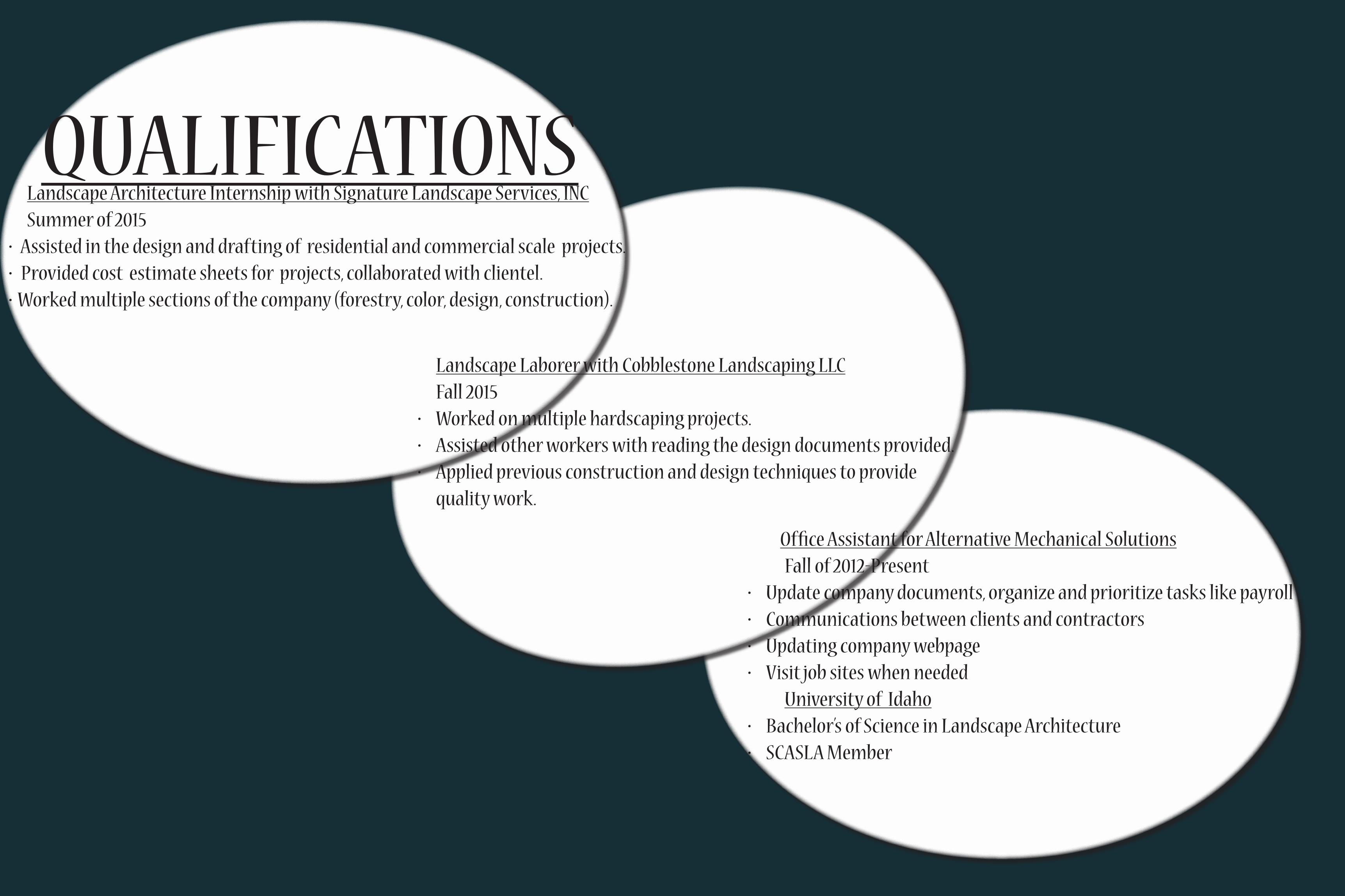
QUALIFICATIONS Landscape Architecture Internship with Signature Landscape Services, INC Summer of 2015
Assisted in the design and drafting of residential and commercial scale projects. Provided cost estimate sheets for projects, collaborated with clientel. Worked multiple sections of the company (forestry, color, design, construction).
•••
Landscape Laborer with Cobblestone Landscaping LLC Fall 2015
Worked on multiple hardscaping projects. Assisted other workers with reading the design documents provided. Applied previous construction and design techniques to provide
quality work.
•••

Office Assistant for Alternative Mechanical Solutions Fall of 2012-Present
Update company documents, organize and prioritize tasks like payroll Communications between clients and contractors Updating company webpage Visit job sites when needed
University of Idaho Bachelor’s of Science in Landscape Architecture SCASLA Member
••••
••
DESIGN PROCESSIdentifytheProblem
EnvisiontheSolution
Strategize
Execute
Goal
Goal
Ethics
QualityofLife
Sustainability
PlaceBasedDesign
Ecology
EconomyStewardship
The design process that I follow is made up of a set of core values and strategic steps to produce a design that is ethically, environmentally and economically beneficial. I intend for all of my designs to have an identifiable purpose in their environment.

PRIEST RIVER REVITALIZATIONThe goal of the Priest River Waterfront project was to revitalize the town and provide concepts for a new waterfront design, a new main street design, as well as provide opportunities for the growth of the town’s economy by providing optimal accessibility for new businesses to be introduced. The program, site inventory and site analysis provided the information necessary to develop a concept for the site that would reach those goals.
Location of the riverHistorical aspects
Recreational opportunityPotential for commercial developmentOpen spaceCommunity support
••••
••
Opportunities Constraints
Strength of economyThreat of tourismLumber millExisting infrastructurePedestrian safetyTraffic flow
•
•••
••
Solution
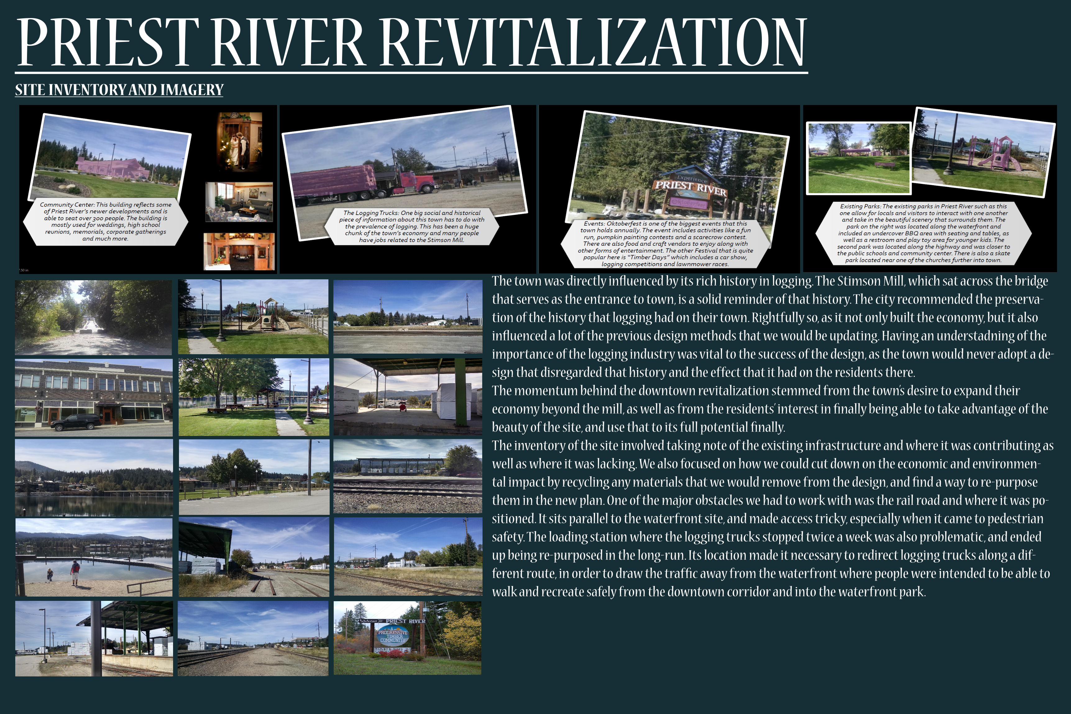
PRIEST RIVER REVITALIZATIONSITEINVENTORYANDIMAGERY
The town was directly influenced by its rich history in logging. The Stimson Mill, which sat across the bridge that serves as the entrance to town, is a solid reminder of that history. The city recommended the preserva-tion of the history that logging had on their town. Rightfully so, as it not only built the economy, but it also influenced a lot of the previous design methods that we would be updating. Having an understadning of the importance of the logging industry was vital to the success of the design, as the town would never adopt a de-sign that disregarded that history and the effect that it had on the residents there.The momentum behind the downtown revitalization stemmed from the town’s desire to expand their economy beyond the mill, as well as from the residents’ interest in finally being able to take advantage of the beauty of the site, and use that to its full potential finally. The inventory of the site involved taking note of the existing infrastructure and where it was contributing as well as where it was lacking. We also focused on how we could cut down on the economic and environmen-tal impact by recycling any materials that we would remove from the design, and find a way to re-purpose them in the new plan. One of the major obstacles we had to work with was the rail road and where it was po-sitioned. It sits parallel to the waterfront site, and made access tricky, especially when it came to pedestrian safety. The loading station where the logging trucks stopped twice a week was also problematic, and ended up being re-purposed in the long-run. Its location made it necessary to redirect logging trucks along a dif-ferent route, in order to draw the traffic away from the waterfront where people were intended to be able to walk and recreate safely from the downtown corridor and into the waterfront park.
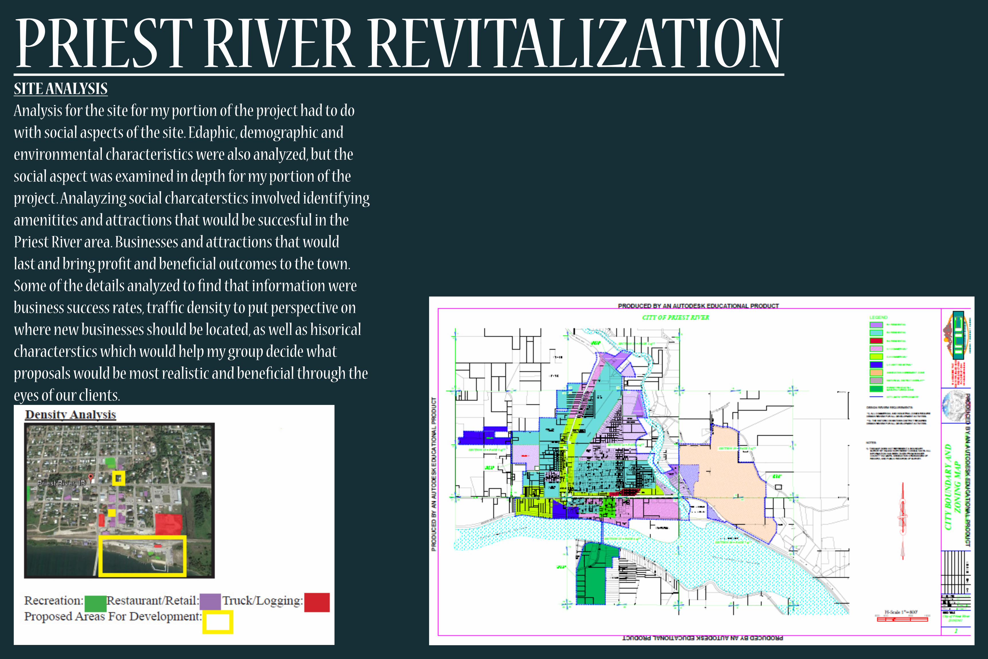
SITEANALYSISAnalysis for the site for my portion of the project had to do with social aspects of the site. Edaphic, demographic and environmental characteristics were also analyzed, but the social aspect was examined in depth for my portion of the project. Analayzing social charcaterstics involved identifying amenitites and attractions that would be succesful in the Priest River area. Businesses and attractions that would last and bring profit and beneficial outcomes to the town. Some of the details analyzed to find that information were business success rates, traffic density to put perspective on where new businesses should be located, as well as hisorical characterstics which would help my group decide what proposals would be most realistic and beneficial through the eyes of our clients.
PRIEST RIVER REVITALIZATION
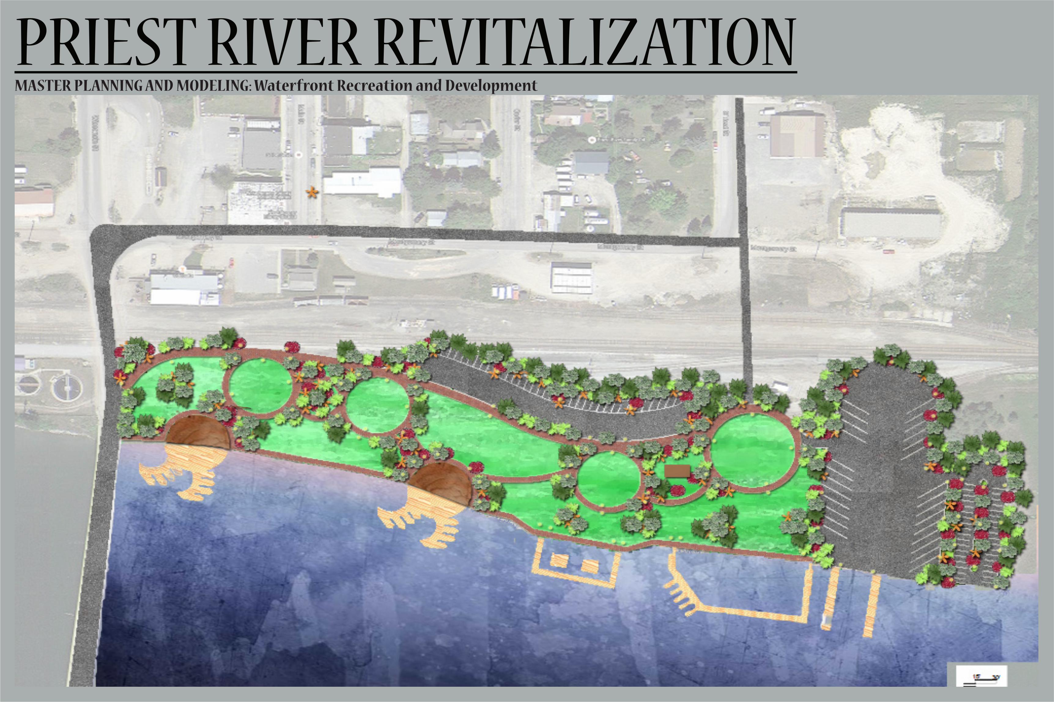
MASTERPLANNINGANDMODELING:WaterfrontRecreationandDevelopment
PRIEST RIVER REVITALIZATION

MOSCOW EASTGATEInterpretation of Landscape

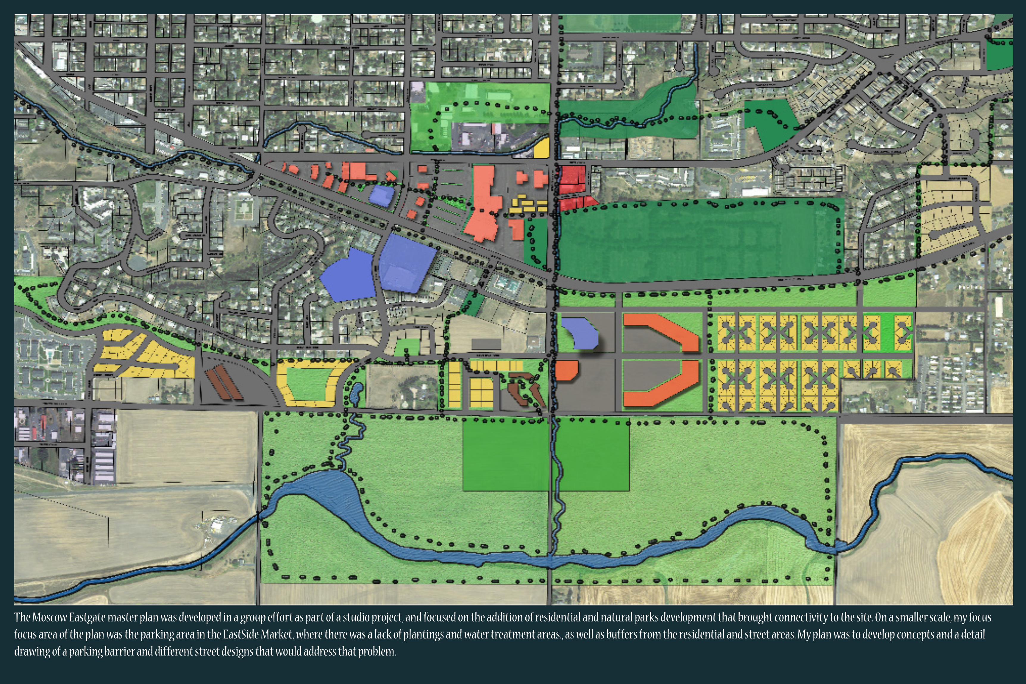
The Moscow Eastgate master plan was developed in a group effort as part of a studio project, and focused on the addition of residential and natural parks development that brought connectivity to the site. On a smaller scale, my focus focus area of the plan was the parking area in the EastSide Market, where there was a lack of plantings and water treatment areas., as well as buffers from the residential and street areas. My plan was to develop concepts and a detail drawing of a parking barrier and different street designs that would address that problem.
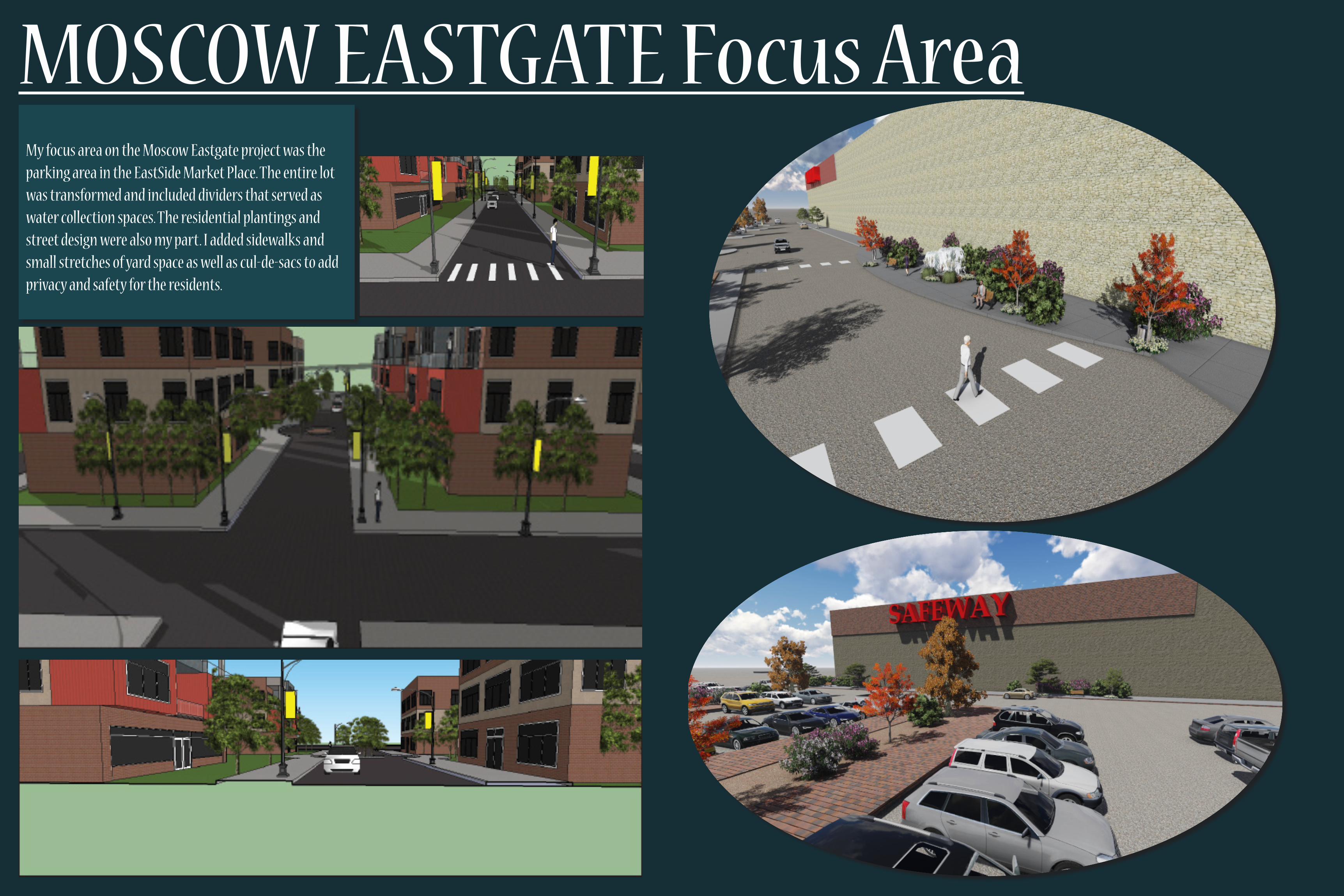
MOSCOW EASTGATE Focus AreaMy focus area on the Moscow Eastgate project was the parking area in the EastSide Market Place. The entire lot was transformed and included dividers that served as water collection spaces. The residential plantings and street design were also my part. I added sidewalks and small stretches of yard space as well as cul-de-sacs to add privacy and safety for the residents.

SOIL STEWARDS FARM
This project was purposed to assist a group of students on the University of Idaho campus called “The Soil Stewards”. They currently do not have anywhere to practice the farming techniques that they are learning in classes. Being that they are learning more sustainable agriculture, my studio decided to develop mutliple concepts for an educational-use farm plot that sat close to campus. The master plan shown is my version of the educational farm. It includes a green house, a crop station, paths wide enough for tractor use, storage space, a small orchard, and an educational area as well as a separate public use area. The site was to be as self sustaining as possible, use natural and drought tolerant plants, and was not to require too much modification to the existing land.

SOIL STEWARDS FARM

The South Hill Remediation Project involved the application of water conservation technologies. The goal was to improve water treatment methods as well as water use efficiency. The project required the use of water retention and detention calculations based off of precipitation and climate data found during the site analysis phase, as well as density requirements as specified in the project program. The methods used were selected based off of their capabilities to remove identified pollutants in run-off that was on-site, such as metals, animal waste and sediment. The results show methods for grey-water and black-water treatment that uphold the water quality standards desired as well as the amount of water that is treated and re-used on-site.
WATER CONSERVATION

WATER CONSERVATIONINFILTRATION AND STORMWATER
Expected Pollutants On Site RunoffLANDSCAPE RUNOFF 94,000 UNITS PER 100mL
(E. COLI) Animal feces, sediment, agricultural or landscaping pollutants like weed killer/pesticides/etc.
BUILDING RUNOFF 263 MICRO-GRAMS PER LITER62 MICRO GRAMS(COPPER)43 MICRO GRAMS (LEAD)
•
•
•
Heavy metals, toxic chemicals and bacteria from floatable materials, trace metals such as calcium, lead and copper
PLAZA RUNOFF TSS: 228 MG/L Sediment erosion, food waste, animal waste, bacteria
RECREATIONAL RUNOFF
TSS: 228 MG/L Leaves and lawn clippings, small wood products, animal wastes, food wastes and street litter, phosphorous
Site Runoff InformationThe site treatment system is going to be 1000 square feet in order to sustain the volume needed to capture the left over 11.97 cubic feet of runoff from the site that has not been absorbed by the parking lot.
The retention basin in this site will be 1000 square feet in order to accommodate the 2 year 24 hour storm precipitation volume of 2.8 inches. This will also take care of any excess runoff that is not caught and treated in the parking lot. As well as treat the parking lot water a second time to further improve water quality. To maximize infiltration class A soils should be used such as sand, this will help remove pollutants such as oils and nutrients that should not be stored in the basin. The bedrock in this system should also allow for good filtration and take care of TSS levels. Will also be a layer of compost in the system so that it provides and captures nutrients that are organic to the system.In order for the filter strip to be effective, the basin also needs to be placed so that the fliter strip is along at least a 1% slope, but no greater than 3%. There will be a buffer between the basin and th eother parts of the site such as recreational areas and lots and buildings.
With the pollutant concentration from this runoff, the filtration that occurs within the filter strip and the gravel bed and soil bed will reduce the concetration of pollutants and allow cleaner water to filter down into the ground.
RETENTION POND ON NORTH END OF SITERETENTION POND ON SOUTH END OF SITE BETWEEN LOTS 3 AND 4
GREY AND BLACK WATER TREATMENTBRIANNA STECKLER
TASK REQUIREMENTS:3 SEPTIC TANKS (43,125/3=14,375 GALLON CAPACITY EACH. 75 GALSX(50 UNITS PER ACREX11.5 ACRES))2 SEPARATE VSF TO HSF WETLAND DESIGNS THROUGH SITEGREEN ROOF GREYWATER TREATMENT SYSTEM
••••L-Shaped Green Roof: 86% Run-off Coefficient
L-Shaped buildings are 17, 828 square feet. Each building uses 12, 544 gallons per month for toilets.White Roofs For Tall Square Buildings: 90% Run-off Coefficient
Sqaure building uses 20, 160 gallons per month just for toilet use (4 weeks).STEP ONE: GREEN ROOF TREATMENT OF RAIN WATER
STEP TWO: SEPTIC TANK TREATMENT SYSTEM FOR BLACK WATERFor this site, there should be one septic tank for every L shaped building. The septic tanks will need to be able to harvest 1900 gallons per day, since the harvested water from the toilet use in all buildings combined comes out to be 1090.13 gallons per day. Based off of this required gallon capacity, the tanks shall be sized to be 162 inches in length, 78 inches in width and 64 inches in depth.
STEP THREE: SEPTIC TO VSF WETLAND TREATMENT
STEP FOUR: PLAN VIEW OF SEPTIC TO VSF SYSTEM
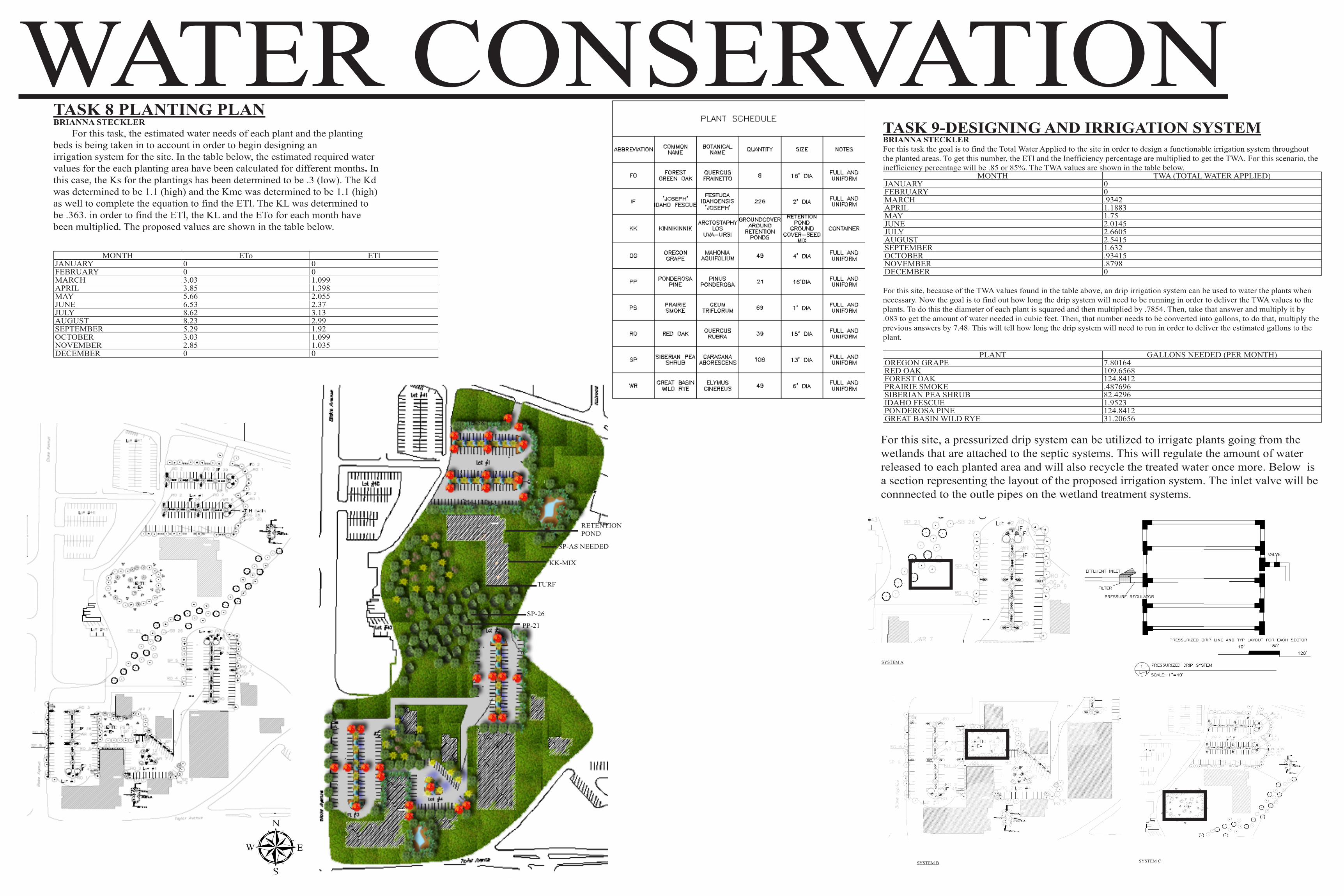
TASK 8 PLANTING PLANBRIANNA STECKLER For this task, the estimated water needs of each plant and the planting beds is being taken in to account in order to begin designing anirrigation system for the site. In the table below, the estimated required water values for the each planting area have been calculated for different months. In this case, the Ks for the plantings has been determined to be .3 (low). The Kd was determined to be 1.1 (high) and the Kmc was determined to be 1.1 (high) as well to complete the equation to find the ETl. The KL was determined to be .363. in order to find the ETl, the KL and the ETo for each month have been multiplied. The proposed values are shown in the table below.
MONTH ETo ETlJANUARY 0 0FEBRUARY 0 0MARCH 3.03 1.099APRIL 3.85 1.398MAY 5.66 2.055JUNE 6.53 2.37JULY 8.62 3.13AUGUST 8.23 2.99SEPTEMBER 5.29 1.92OCTOBER 3.03 1.099NOVEMBER 2.85 1.035DECEMBER 0 0
TASK 9-DESIGNING AND IRRIGATION SYSTEMBRIANNA STECKLERFor this task the goal is to find the Total Water Applied to the site in order to design a functionable irrigation system throughout the planted areas. To get this number, the ETl and the Inefficiency percentage are multiplied to get the TWA. For this scenario, the inefficiency percentage will be .85 or 85%. The TWA values are shown in the table below.
MONTH TWA (TOTAL WATER APPLIED)JANUARY 0FEBRUARY 0MARCH .9342APRIL 1.1883MAY 1.75JUNE 2.0145JULY 2.6605AUGUST 2.5415SEPTEMBER 1.632OCTOBER .93415NOVEMBER .8798DECEMBER 0
For this site, because of the TWA values found in the table above, an drip irrigation system can be used to water the plants when necessary. Now the goal is to find out how long the drip system will need to be running in order to deliver the TWA values to the plants. To do this the diameter of each plant is squared and then multiplied by .7854. Then, take that answer and multiply it by .083 to get the amount of water needed in cubic feet. Then, that number needs to be converted into gallons, to do that, multiply the previous answers by 7.48. This will tell how long the drip system will need to run in order to deliver the estimated gallons to the plant.
PLANT GALLONS NEEDED (PER MONTH)OREGON GRAPE 7.80164RED OAK 109.6568FOREST OAK 124.8412PRAIRIE SMOKE .487696SIBERIAN PEA SHRUB 82.4296IDAHO FESCUE 1.9523PONDEROSA PINE 124.8412GREAT BASIN WILD RYE 31.20656
For this site, a pressurized drip system can be utilized to irrigate plants going from the wetlands that are attached to the septic systems. This will regulate the amount of water released to each planted area and will also recycle the treated water once more. Below is a section representing the layout of the proposed irrigation system. The inlet valve will be connnected to the outle pipes on the wetland treatment systems.
SYSTEM A
SYSTEM B SYSTEM C
PP-21
SP-26
TURF
KK-MIX
SP-AS NEEDED
RETENTIONPOND
IF-58
WATER CONSERVATION

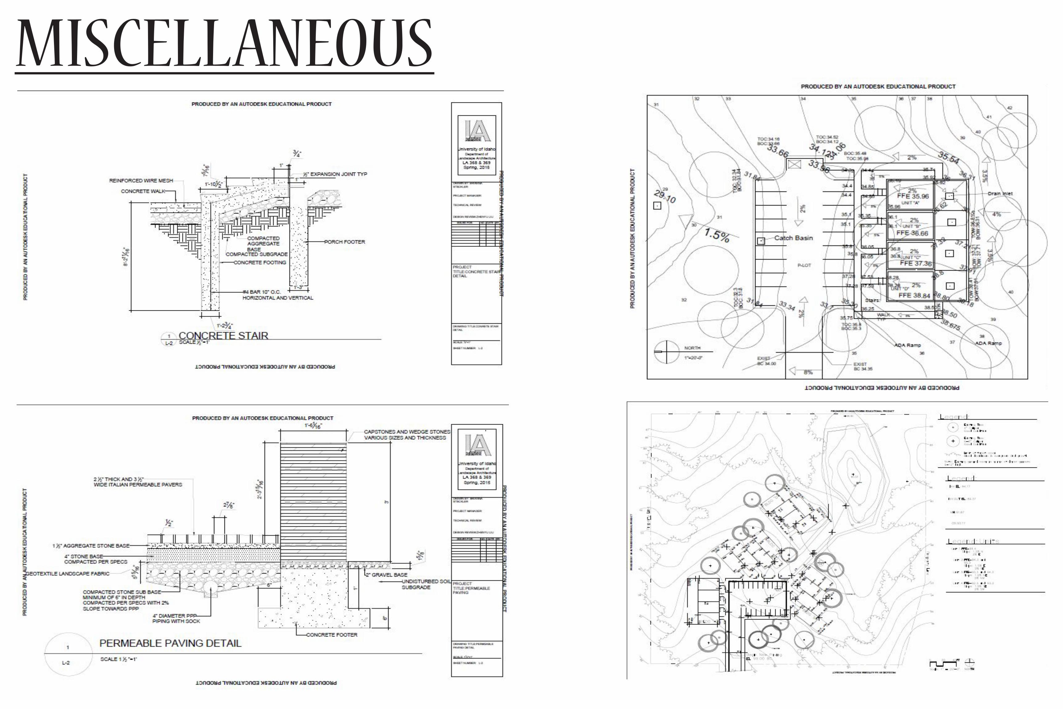
MISCELLANEOUS My construction and my modeling have been skills that I have put to use in every project that I’ve worked on. Some examples of my practice works are shown here.
MISCELLANEOUS