Modell der Baureihe 55 - spur-1-freunde.de
30
Modell der Baureihe 55
Transcript of Modell der Baureihe 55 - spur-1-freunde.de

Modell der Baureihe 55
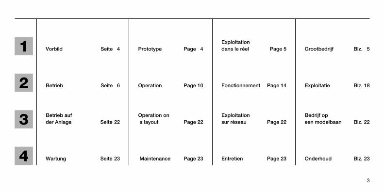
2 Betrieb Seite 6 Operation Page 10 Fonctionnement Page 14 Exploitatie Blz. 18
1 Exploitation Vorbild Seite 4 Prototype Page 4 dans le réel Page 5 Grootbedrijf Blz. 5
3 Betrieb auf Operation on Exploitation Bedrijf opder Anlage Seite 22 a layout Page 22 sur réseau Page 22 een modelbaan Blz. 22
4 Wartung Seite 23 Maintenance Page 23 Entretien Page 23 Onderhoud Blz. 23
3

Die G 81 gehört mit über 5.000 produzierten Stück zu den meistgebautenLoktypen der Welt. Sie wurde dabei nicht nur für die Preußische Eisenbahn(K.P.E.V.) hergestellt. Mehr als 300 Stück wurden für andere deutsche Länder-bahndirektionen bzw. für andere europäische Eisenbahngesellschaften gefertigt.
Die G 81 war auch für die Reichsbahn, die sie unter der Bezeichnung BR 5525-56 einreihte, eine weitverbreitete Lok. Eine Reihe von Loks wurdendabei mit einer Vorlaufachse ausgestattet und als BR 562-8 eingereiht. Auch diese Baureihe wurde bereits von Märklin angeboten.
Trotz ihrer für heutige Verhältnisse geringen Höchstgeschwindigkeit von 55 km/h wurde die letzte Lok dieser Baureihe bei der Deutschen Bundes-bahn erst 1973 außer Dienst gestellt.
Over 5,000 of the G 81 were built, making it the locomotive built in the largestquantities in the world. It was produced for more than just the Prussian Rail-road (K.P.E.V.). More than 300 units were built for other German provincialrailroads and for other European railroads.
The G 81 was also widely used by the German State Railroad and was desig-nated by the latter as the class BR 5525-56. One series of locomotives wasequipped with a pilot truck and designated as the class BR 562-8. This classhas also already been offered by Märklin.
Despite its low maximum speed of 55 km/h (34 mph) (low by today’s standards), the last locomotive of this class was not taken out of service on the German Federal Railroad until 1973.
4
1 Vorbild Prototype

La G 81 appartient au type de locomotive le plus fabriqué au monde et dont5.000 exemplaires ont été fabriqués. Ces machines n'ont pas été construitesuniquement pour les Chemins de fer Prussiens (K.P.E.V.). En effet, plus de300 unités ont été livrées à d'autres administrations ferroviaires allemandesou étrangères.
La G 81 a également été une machine très répandue au sein des effectifs dela Deutsche Reichsbahn sous la dénomination de série BR 5525-56. Une partiedes locomotives, désignée BR 562-8, a reçu un bissel avant. Cette série a aussiété reproduite par Märklin.
Malgré leur faible vitesse limitée à 55 km/h, ce qui est peu de nos jours, leslocomotives de la série 55 sont restées en service à la Deutsche Bundesbahnjusqu'en 1973.
De G 81 behoort, met meer dan 5000 geproduceerde exemplaren, tot hetmeest gebouwde locomotieftype ter wereld. Hij werd niet alleen voor de Pruisische Spoorwegen (K.P.E.V.) gebouwd. Meer dan 300 stuks werden inopdracht van andere Duitse spoorweg-directies, alsmede voor andere Euro-pese spoorwegmaatschappijen geproduceerd.
De G 81 was ook bij de „Reichsbahn“, onder het bedrijfsnummer BR 5525-56,een veel geziene loc. Een aantal locs werd daar met een voorloopas uitgerusten als BR 562-8 genummerd. Ook deze serie is in het verleden reeds doorMärklin aangeboden.
Ondanks de voor huidige begrippen lage maximumsnelheid van 55 km/h,werd de laatste loc van deze serie pas in 1973 door de „Deutschen Bundes-bahn“ buiten dienst gesteld.
1
5
Exploitation dans le réel Grootbedrijf
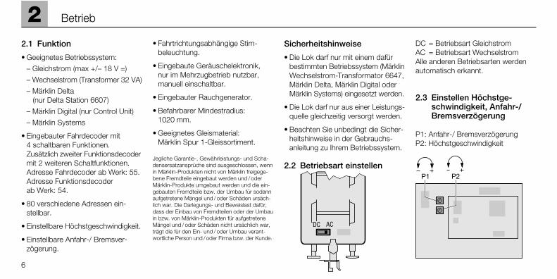
2.1 Funktion
• Geeignetes Betriebssystem:
– Gleichstrom (max +/– 18 V =)
– Wechselstrom (Transformer 32 VA)
– Märklin Delta (nur Delta Station 6607)
– Märklin Digital (nur Control Unit)
– Märklin Systems
• Eingebauter Fahrdecoder mit 4 schaltbaren Funktionen. Zusätzlich zweiter Funktionsdecodermit 2 weiteren Schaltfunktionen.Adresse Fahrdecoder ab Werk: 55.Adresse Funktionsdecoder ab Werk: 54.
• 80 verschiedene Adressen ein-stellbar.
• Einstellbare Höchstgeschwindigkeit.
• Einstellbare Anfahr-/ Bremsver-zögerung.
• Fahrtrichtungsabhängige Stirn-beleuchtung.
• Eingebaute Geräuschelektronik, nur im Mehrzugbetrieb nutzbar,manuell einschaltbar.
• Eingebauter Rauchgenerator.
• Befahrbarer Mindestradius: 1020 mm.
• Geeignetes Gleismaterial: Märklin Spur 1-Gleissortiment.
Jegliche Garantie-, Gewährleistungs- und Scha-densersatzansprüche sind ausgeschlossen, wennin Märklin-Produkten nicht von Märklin freigege-bene Fremdteile eingebaut werden und / oderMärklin-Produkte umgebaut werden und die ein-gebauten Fremdteile bzw. der Umbau für sodannaufgetretene Mängel und / oder Schäden ursäch-lich war. Die Darlegungs- und Beweislast dafür,dass der Einbau von Fremdteilen oder der Umbauin bzw. von Märklin-Produkten für aufgetreteneMängel und / oder Schäden nicht ursächlich war,trägt die für den Ein- und / oder Umbau verant-wortliche Person und / oder Firma bzw. der Kunde.
Sicherheitshinweise
• Die Lok darf nur mit einem dafürbestimmten Betriebssystem (MärklinWechselstrom-Transformator 6647,Märklin Delta, Märklin Digital oderMärklin Systems) eingesetzt werden.
• Die Lok darf nur aus einer Leistungs-quelle gleichzeitig versorgt werden.
• Beachten Sie unbedingt die Sicher-heitshinweise in der Gebrauchs-anleitung zu Ihrem Betriebssystem.
2.2 Betriebsart einstellen
DC = Betriebsart GleichstromAC = Betriebsart WechselstromAlle anderen Betriebsarten werdenautomatisch erkannt.
2.3 Einstellen Höchstge-schwindigkeit, Anfahr-/Bremsverzögerung
P1: Anfahr-/ BremsverzögerungP2: Höchstgeschwindigkeit
6
2 Betrieb

7
Betrieb
2.4 Adresse einstellen (Delta, Digital, Systems)
Fahrdecoder im Tender (=> S. 24).Fahrdecoder unten, Geräuschelek-tronik oben.
Funktionsdecoder in der Lok (=> S 23).
Fahrdecoder
Adresseinstellung an den Schaltern 1bis 8 des 10-poligen Codierschaltersentsprechend nebenstehenderTabelle.
Vorsicht! Fahrdecoder (unten) nichtmit Geräuschelektronik (oben) ver-wechseln!
Schalter 9, 0: Stellung immer auf off
Delta-Adressen: 24, 60, 72, 78
Schaltdecoder
Adresseinstellung an den Schaltern 1bis 8 entsprechend nebenstehenderTabelle.
2
Digital01 – 2 3 – 5 – 7 – – –02 – – 3 – 5 – 7 – – –03 1 – – 4 5 – 7 – – –04 – 2 – 4 5 – 7 – – –05 – – – 4 5 – 7 – – –06 1 – – – 5 – 7 – – –07 – 2 – – 5 – 7 – – –08 – – – – 5 – 7 – – –09 1 – 3 – – 6 7 – – –10 – 2 3 – – 6 7 – – –11 – – 3 – – 6 7 – – –12 1 – – 4 – 6 7 – – –13 – 2 – 4 – 6 7 – – –14 – – – 4 – 6 7 – – –15 1 – – – – 6 7 – – –16 – 2 – – – 6 7 – – –17 – – – – – 6 7 – – –18 1 – 3 – – – 7 – – –19 – 2 3 – – – 7 – – –20 – – 3 – – – 7 – – –21 1 – – 4 – – 7 – – –22 – 2 – 4 – – 7 – – –23 – – – 4 – – 7 – – –24 1 – – – – – 7 – – –25 – 2 – – – – 7 – – –26 – – – – – – 7 – – –27 1 – 3 – 5 – – 8 – –
Digital55 – 2 3 – 5 – – – – –56 – – 3 – 5 – – – – –57 1 – – 4 5 – – – – –58 – 2 – 4 5 – – – – –59 – – – 4 5 – – – – –60 1 – – – 5 – – – – –61 – 2 – – 5 – – – – –62 – – – – 5 – – – – –63 1 – 3 – – 6 – – – –64 – 2 3 – – 6 – – – –65 – – 3 – – 6 – – – –66 1 – – 4 – 6 – – – –67 – 2 – 4 – 6 – – – –68 – – – 4 – 6 – – – –69 1 – – – – 6 – – – –70 – 2 – – – 6 – – – –71 – – – – – 6 – – – –72 1 – 3 – – – – – – –73 – 2 3 – – – – – – –74 – – – – 3 – – – – –75 1 – – – – 4 – – – –76 – – – 2 – 4 – – – –77 – – – – – 4 – – – –78 1 – – – – – – – – –79 – 2 – – – – – – – –80 1 – 3 – 5 – 7 – – –
Digital28 – 2 3 – 5 – – 8 – –29 – – 3 – 5 – – 8 – –30 1 – – 4 5 – – 8 – –31 – 2 – 4 5 – – 8 – –32 – – – 4 5 – – 8 – –33 1 – – – 5 – – 8 – –34 – 2 – – 5 – – 8 – –35 – – – – 5 – – 8 – –36 1 – 3 – – 6 – 8 – –37 – 2 3 – – 6 – 8 – –38 – – 3 – – 6 – 8 – –39 1 – – 4 – 6 – 8 – –40 – 2 – 4 – 6 – 8 – –41 – – – 4 – 6 – 8 – –42 1 – – – – 6 – 8 – –43 – 2 – – – 6 – 8 – –44 – – – – – 6 – 8 – –45 1 – 3 – – – – 8 – –46 – 2 3 – – – – 8 – –47 – – 3 – – – – 8 – –48 1 – – 4 – – – 8 – –49 – 2 – 4 – – – 8 – –50 – – – 4 – – – 8 – –51 1 – – – – – – 8 – –52 – 2 – – – – – 8 – –53 – – – – – – – 8 – –54 1 – 3 – 5 – – – – –
Betrieb
8
2
Funktion
DC 6647 6607 6021 60652
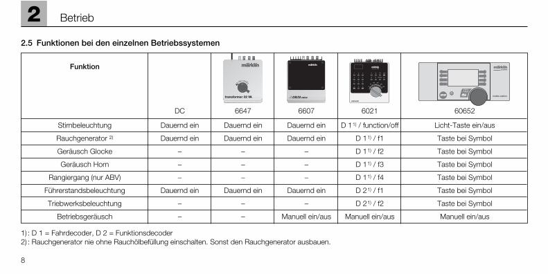
Stirnbeleuchtung Dauernd ein Dauernd ein Dauernd ein D 11) / function/off Licht-Taste ein/aus
Rauchgenerator 2) Dauernd ein Dauernd ein Dauernd ein D 11) / f1 Taste bei Symbol
Geräusch Glocke – – – D 11) / f2 Taste bei Symbol
Geräusch Horn – – – D 11) / f3 Taste bei Symbol
Rangiergang (nur ABV) – – – D 11) / f4 Taste bei Symbol
Führerstandsbeleuchtung Dauernd ein Dauernd ein Dauernd ein D 21) / f1 Taste bei Symbol
Triebwerksbeleuchtung – – – D 21) / f2 Taste bei Symbol
Betriebsgeräusch – – Manuell ein/aus Manuell ein/aus Manuell ein/aus
stationSTOPSTOP mobile station
systems
1) : D 1 = Fahrdecoder, D 2 = Funktionsdecoder2) : Rauchgenerator nie ohne Rauchölbefüllung einschalten. Sonst den Rauchgenerator ausbauen.
2.5 Funktionen bei den einzelnen Betriebssystemen

2.6 Geräuschelektronik
Geräuschelektronik einschalten
Lautstärke einstellenElektronik im Tender Vorsicht! Fahrdecoder (unten) nichtmit Geräuschelektronik (oben) ver-wechseln!
Codierschalter auf Geräusch-elektronik
Werkseinstellung:
Einstellmöglichkeiten
2
9
Betrieb
Schalter 1 2 3 4 5 6 7 8
Stellung On On On On On Off On On
Schalter auf off
Darf nie auf „off“ stehen!
Darf nie auf „off“ stehen!
Automatische Abschaltung deaktiviert.
Zusatzgeräusche nicht aktiviert.
Darf nie auf „off“ stehen!
Stellung für Loks mit Rundschieber.
Immer gleichbleibendes Betriebsgeräusch unabhängig vom Fahrzustand.
Wiedergabe von nur 2 Auspuffschlägenpro Radumdrehung (für den Spielbetriebmit sehr hohen Geschwindigkeiten).
Nr.
1
2
3
4
5
6
7
8
Schalter auf on
Muss immer auf „on“ stehen!
Muss immer auf „on“ stehen!
Das Geräusch schaltet nach einiger Zeitab, sofern die Lok steht und alle (!) Funk-tionen ausgeschaltet sind.
Verschiedene Zusatzgeräusche (Luftpres-ser, Arbeitsgeräusche vom Heizer etc.)aktiviert.
Muss immer auf „on“ stehen!
Typisches Flachschieber-Geräusch beimAusrollen hörbar.
Wiedergabe verschiedener Betriebsge-räusche je nach Fahrzustand der Lok
Wiedergabe von 4 Auspuffschlägen proRadumdrehung (entspricht dem Orignal).

2.1 Function
• Suitable Operating System:
– DC power (max +/– 18 volts DC)
– AC power (32 VA Transformer)
– Märklin Delta (only the 6607 Delta Station)
– Märklin Digital (only the Control Unit)
– Märklin Systems
• Built-in locomotive decoder with 4 controllable auxiliary functions.Also a function decoder with 2 additional auxiliary functions.Address set the factory for thelocomotive decoder: 55. Address set at the factory for thefunction decoder: 54.
• 80 different addresses can be set.
• Adjustable maximum speed.
• Adjustable acceleration / brakingdelay.
• Direction-dependent headlights.
• Built-in sound effects circuit, canonly be used in multi-train operation,can be turned out manually.
• Built-in smoke generator.
• Minimum radius for operation:1,020 mm / 40-5/32”.
• Suitable track material: Märklin 1Gauge track assortment.
No warranty or damage claims shall be acceptedin those cases where parts neither manufacturednor approved by Märklin have been installed inMärklin products or where Märklin products havebeen converted in such a way that the non-Märklinparts or the conversion were causal to the defectsand / or damage arising. The burden of presentingevidence and the burden of proof thereof, that theinstallation of non-Märklin parts or the conversionin or of Märklin products was not causal to thedefects and / or damage arising, is borne by theperson and / or company responsible for the in-stallation and / or conversion, or by the customer.
Safety Warnings
• This locomotive is to be used onlywith an operating system designedfor it (Märklin 6646/6647 AC trans-former, Märklin Delta, Märklin Digitalor Märklin Systems).
• This locomotive must never be supplied with power from morethan one transformer.
• Pay close attention to the safetywarnings in the instructions for your operating system.
2.2 Setting the Mode of Operation
DC = Direct current mode of operation
AC = Alternating current mode of operation
All other modes of operation areautomatically recognized.
2.3 Setting Maximum Speed,Acceleration / Braking Delay
P1: Acceleration / braking delayP2: Maximum speed
10
2 Operation

2
11
Operation
2.4 Setting the Address (Delta, Digital, Systems)
Locomotive decoder in the tender(=> Page 24). Locomotive decoder isabove, sound effects circuit is below.
Function decoder in the locomotive(=> Page 23).
Locomotive decoder
Setting the address with switches 1though 8 of the 10 coding switchesas shown in the table nearby.
Caution! Do not confuse the locomo-tive decoder (below) with the soundeffects circuit (above)!
Switch 9,0: Always set at off.
Delta addresses: 24, 60, 72, 78
Function decoder
Setting the address with switches 1through 8 as shown in the table nearby.
Digital01 – 2 3 – 5 – 7 – – –02 – – 3 – 5 – 7 – – –03 1 – – 4 5 – 7 – – –04 – 2 – 4 5 – 7 – – –05 – – – 4 5 – 7 – – –06 1 – – – 5 – 7 – – –07 – 2 – – 5 – 7 – – –08 – – – – 5 – 7 – – –09 1 – 3 – – 6 7 – – –10 – 2 3 – – 6 7 – – –11 – – 3 – – 6 7 – – –12 1 – – 4 – 6 7 – – –13 – 2 – 4 – 6 7 – – –14 – – – 4 – 6 7 – – –15 1 – – – – 6 7 – – –16 – 2 – – – 6 7 – – –17 – – – – – 6 7 – – –18 1 – 3 – – – 7 – – –19 – 2 3 – – – 7 – – –20 – – 3 – – – 7 – – –21 1 – – 4 – – 7 – – –22 – 2 – 4 – – 7 – – –23 – – – 4 – – 7 – – –24 1 – – – – – 7 – – –25 – 2 – – – – 7 – – –26 – – – – – – 7 – – –27 1 – 3 – 5 – – 8 – –
Digital55 – 2 3 – 5 – – – – –56 – – 3 – 5 – – – – –57 1 – – 4 5 – – – – –58 – 2 – 4 5 – – – – –59 – – – 4 5 – – – – –60 1 – – – 5 – – – – –61 – 2 – – 5 – – – – –62 – – – – 5 – – – – –63 1 – 3 – – 6 – – – –64 – 2 3 – – 6 – – – –65 – – 3 – – 6 – – – –66 1 – – 4 – 6 – – – –67 – 2 – 4 – 6 – – – –68 – – – 4 – 6 – – – –69 1 – – – – 6 – – – –70 – 2 – – – 6 – – – –71 – – – – – 6 – – – –72 1 – 3 – – – – – – –73 – 2 3 – – – – – – –74 – – – – 3 – – – – –75 1 – – – – 4 – – – –76 – – – 2 – 4 – – – –77 – – – – – 4 – – – –78 1 – – – – – – – – –79 – 2 – – – – – – – –80 1 – 3 – 5 – 7 – – –
Digital28 – 2 3 – 5 – – 8 – –29 – – 3 – 5 – – 8 – –30 1 – – 4 5 – – 8 – –31 – 2 – 4 5 – – 8 – –32 – – – 4 5 – – 8 – –33 1 – – – 5 – – 8 – –34 – 2 – – 5 – – 8 – –35 – – – – 5 – – 8 – –36 1 – 3 – – 6 – 8 – –37 – 2 3 – – 6 – 8 – –38 – – 3 – – 6 – 8 – –39 1 – – 4 – 6 – 8 – –40 – 2 – 4 – 6 – 8 – –41 – – – 4 – 6 – 8 – –42 1 – – – – 6 – 8 – –43 – 2 – – – 6 – 8 – –44 – – – – – 6 – 8 – –45 1 – 3 – – – – 8 – –46 – 2 3 – – – – 8 – –47 – – 3 – – – – 8 – –48 1 – – 4 – – – 8 – –49 – 2 – 4 – – – 8 – –50 – – – 4 – – – 8 – –51 1 – – – – – – 8 – –52 – 2 – – – – – 8 – –53 – – – – – – – 8 – –54 1 – 3 – 5 – – – – –
12
2 Operation
Function
DC 6647 6607 6021 60652
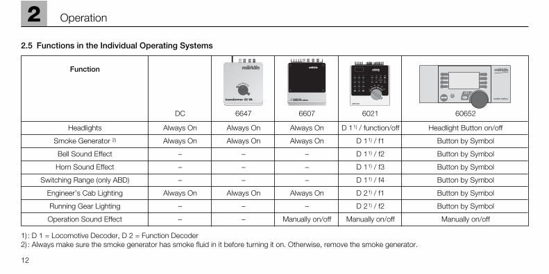
Headlights Always On Always On Always On D 11) / function/off Headlight Button on/off
Smoke Generator 2) Always On Always On Always On D 11) / f1 Button by Symbol
Bell Sound Effect – – – D 11) / f2 Button by Symbol
Horn Sound Effect – – – D 11) / f3 Button by Symbol
Switching Range (only ABD) – – – D 11) / f4 Button by Symbol
Engineer’s Cab Lighting Always On Always On Always On D 21) / f1 Button by Symbol
Running Gear Lighting – – – D 21) / f2 Button by Symbol
Operation Sound Effect – – Manually on/off Manually on/off Manually on/off
stationSTOPSTOP mobile station
systems
1) : D 1 = Locomotive Decoder, D 2 = Function Decoder2) : Always make sure the smoke generator has smoke fluid in it before turning it on. Otherwise, remove the smoke generator.
2.5 Functions in the Individual Operating Systems

2
13
Operation
2.6 Sound Effects Circuit
Turning the Sound Effects Circuit On
Setting the VolumeCircuit in the tender Caution! Do not confuse the locomo-tive decoder (below) with the soundeffects circuit (above)!
Coding Switches on the SoundEffects Circuit
Factory Settings:
Switch 1 2 3 4 5 6 7 8
Setting On On On On On Off On On
Switch at off
Must never be set at “off”!
Must never be set at “off”!
Automatic shutoff deactivated.
Additional sound effects not activate.
Must never be set at “off”!
Setting for locomotives with round slide valve.
The same sound effects of the locomotivein operation, regardless of its operatingstatus.
Reproduction of only 2 exhaust strokesper wheel revolution (for operation of thelocomotive at very high speeds).
No.
1
2
3
4
5
6
7
8
Switch at on
Must always be set at “on”!
Must always be set at “on”!
The sound effects are turned off after a fewminutes as long as the locomotive is at astandstill and all (!) functions are shut off.
Different additional sound effects (air compressor, work sounds of the fire-man, etc.) activated.
Must always be set at “on”!
Tyical flat slide valve noise can be heardduring coasting.
Reproduction of different sound effects,depending on the operating status of thelocomotive.
Reproduction of 4 exhaust strokes per wheel revolution (the same as the original).
Possible Settings

2.1 Fonctionnement
• Systèmes d’exploitation appropriés:– Courant continu (max. +/– 18 V =)– Courant alternatif
(transformateur 32 VA)– Märklin Delta
(uniquement Delta Station 6607)– Märklin Digital
(uniquement Control Unit)– Märklin Systems
• Décodeur de marche intégré avec4 fonctions commutables. Complé-mentairement, décodeur de fonc-tions avec 2 autres fonctions com-mutables. Adresse du décodeur de marche encodée en usine: 55.Adresse du décodeur de fonctionsencodée en usine: 54.
• 80 adresses différentes disponibles.
• Vitesse maximale réglable.
• Temporisation d’accélération-freinage réglable.
• Eclairage des feux de signalisationavec inversion selon le sens demarche.
• Bruiteur électronique intégré, utili-sable uniquement en conduite multitrain, activable manuellement.
• Générateur fumigène intégré.
• Rayon minimal d’inscription encourbe: 1020 mm.
• Matériel de voie approprié: Assorti-ment de voie Märklin Echelle 1.
Tout recours à une garantie commerciale ou contractuelle ou à une demande de dommages-intérêt est exclu si des pièces non autorisées parMärklin sont intégrées dans les produits Märklinet / ou si les produits Märklin sont transformés etque les pièces d’autres fabricants montées ou latransformation constituent la cause des défautset / ou dommages apparus. C’est à la personneet / ou la société responsable du montage / de latransformation ou au client qu’incombe la chargede prouver que le montage des pièces d’autresfabricants sur des produits Märklin ou la transfor-mation des produits Märklin n’est pas à l’originedes défauts et ou dommages apparus.
Remarques importantes sur la sécurité• La locomotive ne peut être mise en
service qu’avec un système d’exploi-tation adéquat (Märklin courantalternatif - transformateur 6647,Märklin Delta, Märklin Digital ouMärklin Systems).
• La locomotive ne peut être alimentéeen courant que par une seule sourcede courant.
• Veuillez impérativement respecter lesremarques sur la sécurité décritesdans le mode d’emploi en ce quiconcerne le système d’exploitation.
2.2 Réglage du mode d’exploitation
DC = Mode courant continu.AC = Mode courant alternatif.Tous les autres modes d’exploitationsont automatiquement détectés.
2.3 Réglage de la vitesse maxi-male, de la temporisationd’accélération-freinage
P1: Temporisation d’accélération-freinage.
P2: Vitesse maximale.
14
2 Fonctionnement

2.4 Réglage de l’adresse(Delta, Digital, Systems)
Décodeur de marche dans le tender(=> page 24). Décodeur de marcheau-dessus, bruiteur électronique endessous.
Décodeur de fonctions dans la loco(=> page 23).
Décodeur de marche.
Réglage de l’adresse via les sélec-teurs 1 à 8 du clavier de codage à 10 sélecteurs selon le tableau decodage ci-contre.
Attention! Ne pas confondre le déco-deur de marche (en dessous) avec lebruiteur électronique (au-dessus)!
Sélecteurs 9, 0: toujours les posi-tionner sur off.
Adresses Delta: 24, 60, 72, 78.
Décodeur de commutation.
Réglage de l’adresse via les sélec-teurs 1 à 8 selon le tableau ci-contre.
2
15
Fonctionnement
Digital01 – 2 3 – 5 – 7 – – –02 – – 3 – 5 – 7 – – –03 1 – – 4 5 – 7 – – –04 – 2 – 4 5 – 7 – – –05 – – – 4 5 – 7 – – –06 1 – – – 5 – 7 – – –07 – 2 – – 5 – 7 – – –08 – – – – 5 – 7 – – –09 1 – 3 – – 6 7 – – –10 – 2 3 – – 6 7 – – –11 – – 3 – – 6 7 – – –12 1 – – 4 – 6 7 – – –13 – 2 – 4 – 6 7 – – –14 – – – 4 – 6 7 – – –15 1 – – – – 6 7 – – –16 – 2 – – – 6 7 – – –17 – – – – – 6 7 – – –18 1 – 3 – – – 7 – – –19 – 2 3 – – – 7 – – –20 – – 3 – – – 7 – – –21 1 – – 4 – – 7 – – –22 – 2 – 4 – – 7 – – –23 – – – 4 – – 7 – – –24 1 – – – – – 7 – – –25 – 2 – – – – 7 – – –26 – – – – – – 7 – – –27 1 – 3 – 5 – – 8 – –
Digital55 – 2 3 – 5 – – – – –56 – – 3 – 5 – – – – –57 1 – – 4 5 – – – – –58 – 2 – 4 5 – – – – –59 – – – 4 5 – – – – –60 1 – – – 5 – – – – –61 – 2 – – 5 – – – – –62 – – – – 5 – – – – –63 1 – 3 – – 6 – – – –64 – 2 3 – – 6 – – – –65 – – 3 – – 6 – – – –66 1 – – 4 – 6 – – – –67 – 2 – 4 – 6 – – – –68 – – – 4 – 6 – – – –69 1 – – – – 6 – – – –70 – 2 – – – 6 – – – –71 – – – – – 6 – – – –72 1 – 3 – – – – – – –73 – 2 3 – – – – – – –74 – – – – 3 – – – – –75 1 – – – – 4 – – – –76 – – – 2 – 4 – – – –77 – – – – – 4 – – – –78 1 – – – – – – – – –79 – 2 – – – – – – – –80 1 – 3 – 5 – 7 – – –
Digital28 – 2 3 – 5 – – 8 – –29 – – 3 – 5 – – 8 – –30 1 – – 4 5 – – 8 – –31 – 2 – 4 5 – – 8 – –32 – – – 4 5 – – 8 – –33 1 – – – 5 – – 8 – –34 – 2 – – 5 – – 8 – –35 – – – – 5 – – 8 – –36 1 – 3 – – 6 – 8 – –37 – 2 3 – – 6 – 8 – –38 – – 3 – – 6 – 8 – –39 1 – – 4 – 6 – 8 – –40 – 2 – 4 – 6 – 8 – –41 – – – 4 – 6 – 8 – –42 1 – – – – 6 – 8 – –43 – 2 – – – 6 – 8 – –44 – – – – – 6 – 8 – –45 1 – 3 – – – – 8 – –46 – 2 3 – – – – 8 – –47 – – 3 – – – – 8 – –48 1 – – 4 – – – 8 – –49 – 2 – 4 – – – 8 – –50 – – – 4 – – – 8 – –51 1 – – – – – – 8 – –52 – 2 – – – – – 8 – –53 – – – – – – – 8 – –54 1 – 3 – 5 – – – – –

16
2 Fonctionnement
Fonction
DC 6647 6607 6021 60652
Feux de signalisation Activé en permanence Activé en permanence Activé en permanence D 11) / function/off Touche éclairage feux on/off
Générateur fumigène 2) Activé en permanence Activé en permanence Activé en permanence D 11) / f1 Touche près du symbole
Bruitage cloche – – – D 11) / f2 Touche près du symbole
Bruitage klaxon – – – D 11) / f3 Touche près du symbole
Mode manœuvre (uniquement ABV) – – – D 11) / f4 Touche près du symbole
Eclairage poste de conduite Activé en permanence Activé en permanence Activé en permanence D 21) / f1 Touche près du symbole
Eclairage mécanisme de roulement – – – D 21) / f2 Touche près du symbole
Bruitage moteur – – Manuel on/off Manuel on/off Manuel on/off
stationSTOPSTOP mobile station
systems
1) : D 1 = décodeur de marche, D 2 = décodeur de fonctions2) : Ne jamais activer le générateur fumigène sans liquide fumigène. Sinon, enlever le générateur.
2.5 Fonctions relatives aux divers systèmes d’exploitation
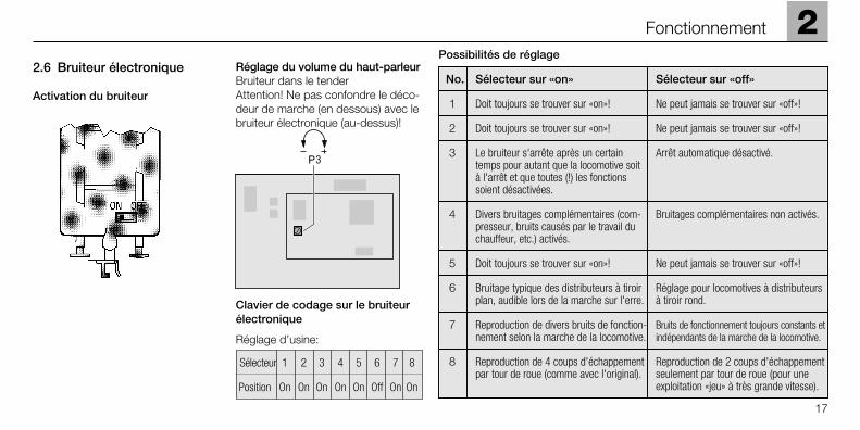
2.6 Bruiteur électronique
Activation du bruiteur
Réglage du volume du haut-parleurBruiteur dans le tender Attention! Ne pas confondre le déco-deur de marche (en dessous) avec lebruiteur électronique (au-dessus)!
Clavier de codage sur le bruiteurélectronique
Réglage d’usine:
2
17
Fonctionnement
Sélecteur 1 2 3 4 5 6 7 8
Position On On On On On Off On On
Sélecteur sur «off»
Ne peut jamais se trouver sur «off»!
Ne peut jamais se trouver sur «off»!
Arrêt automatique désactivé.
Bruitages complémentaires non activés.
Ne peut jamais se trouver sur «off»!
Réglage pour locomotives à distributeursà tiroir rond.
Bruits de fonctionnement toujours constants etindépendants de la marche de la locomotive.
Reproduction de 2 coups d'échappementseulement par tour de roue (pour uneexploitation «jeu» à très grande vitesse).
No.
1
2
3
4
5
6
7
8
Sélecteur sur «on»
Doit toujours se trouver sur «on»!
Doit toujours se trouver sur «on»!
Le bruiteur s'arrête après un certaintemps pour autant que la locomotive soità l'arrêt et que toutes (!) les fonctionssoient désactivées.
Divers bruitages complémentaires (com-presseur, bruits causés par le travail duchauffeur, etc.) activés.
Doit toujours se trouver sur «on»!
Bruitage typique des distributeurs à tiroirplan, audible lors de la marche sur l'erre.
Reproduction de divers bruits de fonction-nement selon la marche de la locomotive.
Reproduction de 4 coups d'échappementpar tour de roue (comme avec l'original).
Possibilités de réglage

2.1 Werking
• Geschikt bedrijfssysteem:
– Gelijkstroom (max +/– 18 V =)
– Wisselstroom (Transformer 32 VA)
– Märklin Delta (alleen Delta Station 6607)
– Märklin Digital (alleen Control Unit)
– Märklin Systems
• Ingebouwde rijdecoder met 4 schakelbare functies. Daarnaasteen extra functiedecoder met 2 schakelfuncties. Adres rijdecoder vanaf de fabriek: 55.Adres van de functiedecoder vanafde fabriek: 54.
• 80 verschillende instelbare adressen.
• Instelbare maximumsnelheid.
• Instelbare optrek- en afremver-traging.
• Rijrichtingafhankelijke frontver-lichting.
• Ingebouwde geluidselektronica, te gebruiken in het meer-treinen-bedrijf, handmatig inschakelbaar.
• Ingebouwde rookgenerator.
• Minimale berijdbare radius: 1020 mm.
• Geschikt railmateriaal: Märklin 1-railassortiment.
Elke aanspraak op garantie en schadevergoedingis uitgesloten, wanneer in Märklin-producten nietdoor Märklin vrijgegeven vreemde onderdeleningebouwd en / of Märklin-producten omgebouwdworden en de ingebouwde vreemde onderdelenresp. de ombouw oorzaak van nadien opgetredendefecten en / of schade was. De aantoonplicht en de bewijslijst daaromtrent, dat de inbouw vanvreemde onderdelen in Märklin-producten of deombouw van Märklin-producten niet de oorzaakvan opgetreden defecten en / of schade is geweest,berust bij de voor de inbouw en/of ombouw verantwoordelijke persoon en / of firma danwel bij de klant.
Veiligheidsvoorschriften
• De loc mag alleen met een daarvo-or bestemd bedrjfssysteem (Märklinwisselstroom transformator 6647,Märklin Delta, Märklin digitaal ofMärklin Systems) gebruikt worden.
• De loc mag niet vanuit meer danéén stroomvoorziening gelijktijdiggevoed worden.
• Lees ook aandachtig de veiligheids-voorschriften in de gebruiksaan-wijzing van uw bedrijfssysteem.
2.2 Bedrijfs-systeem instellen
DC = bedrijfssysteem gelijkstroomAC = bedrijfssysteem wisselstroomAlle andere bedrijfssystemen wordenautomatisch herkend.
2.3 Instellen van de maxi-mumsnelheid, optrek- /afremvertraging
P1: optrek-/ afremvertragingP2: maximumsnelheid
18
2 Exploitatie

2.4 Adres instellen (Delta, Digital, Systems)
Rijdecoder in de tender (=> pag. 24).Rijdecoder onder, geluidselektronicaboven.
Functiedecoder in de loc (=> pag. 23).
Rijdecoder
Adresinstelling met de schakelaars 1 t/m 8 van de 10-polige codeer-schakelaar overeenkomstig onder-staande tabel.
Pas op! Rijdecoder (onder) niet ver-wisselen met de geluidselektronica(boven)!
Schakelaars 9 en 0: altijd op off.
Delta-adressen: 24, 60, 72 of 78.
Functiedecoder
Adresinstelling met de schakelaars 1 t/m 8 van de codeerschakelaarovereenkomstig onderstaande tabel.
2
19
Exploitatie
Digital01 – 2 3 – 5 – 7 – – –02 – – 3 – 5 – 7 – – –03 1 – – 4 5 – 7 – – –04 – 2 – 4 5 – 7 – – –05 – – – 4 5 – 7 – – –06 1 – – – 5 – 7 – – –07 – 2 – – 5 – 7 – – –08 – – – – 5 – 7 – – –09 1 – 3 – – 6 7 – – –10 – 2 3 – – 6 7 – – –11 – – 3 – – 6 7 – – –12 1 – – 4 – 6 7 – – –13 – 2 – 4 – 6 7 – – –14 – – – 4 – 6 7 – – –15 1 – – – – 6 7 – – –16 – 2 – – – 6 7 – – –17 – – – – – 6 7 – – –18 1 – 3 – – – 7 – – –19 – 2 3 – – – 7 – – –20 – – 3 – – – 7 – – –21 1 – – 4 – – 7 – – –22 – 2 – 4 – – 7 – – –23 – – – 4 – – 7 – – –24 1 – – – – – 7 – – –25 – 2 – – – – 7 – – –26 – – – – – – 7 – – –27 1 – 3 – 5 – – 8 – –
Digital55 – 2 3 – 5 – – – – –56 – – 3 – 5 – – – – –57 1 – – 4 5 – – – – –58 – 2 – 4 5 – – – – –59 – – – 4 5 – – – – –60 1 – – – 5 – – – – –61 – 2 – – 5 – – – – –62 – – – – 5 – – – – –63 1 – 3 – – 6 – – – –64 – 2 3 – – 6 – – – –65 – – 3 – – 6 – – – –66 1 – – 4 – 6 – – – –67 – 2 – 4 – 6 – – – –68 – – – 4 – 6 – – – –69 1 – – – – 6 – – – –70 – 2 – – – 6 – – – –71 – – – – – 6 – – – –72 1 – 3 – – – – – – –73 – 2 3 – – – – – – –74 – – – – 3 – – – – –75 1 – – – – 4 – – – –76 – – – 2 – 4 – – – –77 – – – – – 4 – – – –78 1 – – – – – – – – –79 – 2 – – – – – – – –80 1 – 3 – 5 – 7 – – –
Digital28 – 2 3 – 5 – – 8 – –29 – – 3 – 5 – – 8 – –30 1 – – 4 5 – – 8 – –31 – 2 – 4 5 – – 8 – –32 – – – 4 5 – – 8 – –33 1 – – – 5 – – 8 – –34 – 2 – – 5 – – 8 – –35 – – – – 5 – – 8 – –36 1 – 3 – – 6 – 8 – –37 – 2 3 – – 6 – 8 – –38 – – 3 – – 6 – 8 – –39 1 – – 4 – 6 – 8 – –40 – 2 – 4 – 6 – 8 – –41 – – – 4 – 6 – 8 – –42 1 – – – – 6 – 8 – –43 – 2 – – – 6 – 8 – –44 – – – – – 6 – 8 – –45 1 – 3 – – – – 8 – –46 – 2 3 – – – – 8 – –47 – – 3 – – – – 8 – –48 1 – – 4 – – – 8 – –49 – 2 – 4 – – – 8 – –50 – – – 4 – – – 8 – –51 1 – – – – – – 8 – –52 – 2 – – – – – 8 – –53 – – – – – – – 8 – –54 1 – 3 – 5 – – – – –
20
2 Exploitatie
Werking
DC 6647 6607 6021 60652
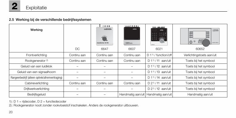
Frontverlichting Continu aan Continu aan Continu aan D 11) / function/off Verlichtingstoets aan/uit
Rookgenerator 2) Continu aan Continu aan Continu aan D 11) / f1 aan/uit Toets bij het symbool
Geluid van een luidklok – – – D 11) / f2 aan/uit Toets bij het symbool
Geluid van een signaalhoorn – – – D 11) / f3 aan/uit Toets bij het symbool
Rangeerbedrijf (alleen optrek/afremvertraging) – – – D 11) / f4 aan/uit Toets bij het symbool
Cabineverlichting Continu aan Continu aan Continu aan D 21) / f1 aan/uit Toets bij het symbool
Drijfwerkverlichting – – – D 21) / f2 aan/uit Toets bij het symbool
Bedrijfsgeluid – – Handmatig aan/uit Handmatig aan/uit Handmatig aan/uit
stationSTOPSTOP mobile station
systems
1) : D 1 = rijdecoder, D 2 = functiedecoder2) : Rookgenerator nooit zonder rookvloeistof inschakelen. Anders de rookgenerator uitbouwen.
2.5 Werking bij de verschillende bedrijfssystemen

2
21
Exploitatie
2.6 Geluidselektronica
Geluidselektronica inschakelen
Volume instellenElektronica in de tenderPas op! Rijdecoder (onder) niet ver-wisselen met de geluidselektronica(boven)
Codeerschakelaar op de geluids-elektronica
Instelling vanaf de fabriek:
Instelmogelijkheden
Schakelaar 1 2 3 4 5 6 7 8
Stand On On On On On Off On On
Schakelaar op off
Mag nooit op “off” staan!
Mag nooit op “off” staan!
Het automatische uitschakelen is niet actief.
Extra geluiden niet geactiveerd.
Mag nooit op “off” staan!
Stand voor de locs met een draaischuif.
Altijd gelijkblijvend geluidsbeeld onaf-hankelijk van de rijstand.
Weergave van 2 uitlaatslagen per wiel-omwenteling (voor het speelbedrijf metzeer hoge rijsnelheden).
Nr.
1
2
3
4
5
6
7
8
Schakelaar op on
Moet altijd op “on” staan!
Moet altijd op “on” staan!
Het geluid schakelt na enige tijd uit, voorzover de loc stilstaat en alle functiesuitgeschakeld zijn.
Verschillende extra geluiden (luchtpomp, het werken van de stoker e.d.) geactiveerd.
Moet altijd op “on” staan!
Het typische geluid van een bakschuif bij het uitlopen van de loc hoorbaar.
Weergeven van de verschillende bedrijfs-geluiden afhankelijk van de rijstand vande loc.
Weergave van 4 uitlaatslagen per wielom-wenteling (overeenkomstig het origineel).
3 Betrieb auf der Anlage Operation on a layout Exploitation sur réseau Bedrijf op een modelbaan
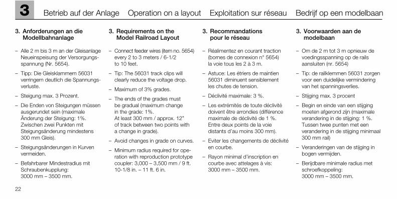
3. Anforderungen an dieModellbahnanlage
– Alle 2 m bis 3 m an der GleisanlageNeueinspeisung der Versorgungs-spannung (Nr. 5654).
– Tipp: Die Gleisklammern 56031verringern deutlich die Spannungs-verluste.
– Steigung max. 3 Prozent.
– Die Enden von Steigungen müssenausgerundet sein (maximale Änderung der Steigung: 1%. Zwischen zwei Punkten mit Steigungsänderung mindestens300 mm Gleis).
– Steigungsänderungen in Kurvenvermeiden.
– Befahrbarer Mindestradius mitSchraubenkupplung: 3000 mm – 3500 mm.
3. Requirements on the Model Railroad Layout
– Connect feeder wires (item no. 5654)every 2 to 3 meters / 6-1/2 to 10 feet.
– Tip: The 56031 track clips willclearly reduce the voltage drop.
– Maximum of 3% grades.
– The ends of the grades must be gradual (maximum change in the grade: 1%. At least 300 mm / approx. 12” of track between two points with a change in grade).
– Avoid changes in grade on curves.
– Minimum radius required for ope-ration with reproduction prototypecoupler: 3,000 – 3,500 mm / 9 ft.10-1/8 in. – 11 ft. 6 in.
3. Recommandations pour le réseau
– Réalimentez en courant traction(bornes de connexion n° 5654) la voie tous les 2 à 3 m.
– Astuce: Les étriers de maintien56031 diminuent sensiblement les chutes de tension.
– Déclivité maximale: 3 %.
– Les extrémités de toute déclivitédoivent être arrondies (différencemaximale de déclivité de 1 %. Entre deux points de la voiedistants d’au moins 300 mm).
– Eviter les changements de déclivitéen courbe.
– Rayon minimal d’inscription encourbe avec attelages à vis: 3000 mm – 3500 mm.
3. Voorwaarden aan demodelbaan
– Om de 2 m tot 3 m opnieuw devoedingsspanning op de railsaansluiten (nr. 5654)
– Tip: de railklemmen 56031 zorgenvoor een duidelijke verminderingvan het spanningsverlies.
– Stijging max. 3 procent
– Begin en einde van een stijgingmoeten afgerond zijn (maximaleverandering in de stijging: 1 %.Tussen twee punten met eenverandering in de stijging minimaal300 mm rail)
– Veranderingen van de stijging inbogen vermijden.
– Berijdbare minimale radius metschroefkoppeling: 3000 mm – 3500 mm.
22

4
23
Wartung Maintenance Entretien Onderhoud
4.1 Lokgehäuse abnehmen
Removing the locomotive body
Enlever la caisse de la locomotive
Locomotiefkap verwijderen

24
4 Wartung Maintenance Entretien Onderhoud
4.2 Tendergehäuse abnehmen
Removing the tender body
Enlever la caisse du tender
Tenderkap verwijderen
4
25
Wartung Maintenance Entretien Onderhoud
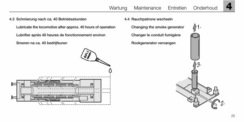
4.3 Schmierung nach ca. 40 Betriebsstunden
Lubricate the locomotive after approx. 40 hours of operation
Lubrifier après 40 heures de fonctionnement environ
Smeren na ca. 40 bedrijfsuren
4.4 Rauchpatrone wechseln
Changing the smoke generator
Changer le conduit fumigène
Rookgenerator vervangen
3.
2.
1.

4.5 Gehäuse aufsetzen
Auf gerade Stellung der Rauchpatroneachten. Zentrierhülse für den Rauchgeneratordurch den Schornstein von obenwieder einsetzen.
4.5 Putting the body back on
Make sure that the smoke generatoris inserted straight down in thesmokestack.Insert the centering sleeve for thesmoke generator into the smoke-stack from above.
4.5 Reposer la caisse
Faire attention à bien positionner leconduit fumigène. Remettre la douille de centrage pour le fumigène par le dessus de la cheminée.
4.5 Kap terug plaatsen
Let op dat de rookgenerator rechtstaat.Centreerhuls voor de rookgeneratordoor de schoorsteen van bovenafweer inzetten.
26
4 Wartung Maintenance Entretien Onderhoud

4
27
Wartung Maintenance Entretien Onderhoud
4.6 Haftreifen wechseln
Changing traction tires
Changer les bandages d'adhérence
Antislip band vervangen
4.7 Figuren einkleben
Gluing figures in place
Coller les figurines
Figuren vastlijmen
591 500

28
4 Wartung Maintenance Entretien Onderhoud
4.8 Schleifer wechseln
Changing electrical pickups
Changer le patin
Sleper vervangen
4.9 Rauchöl nachfüllen
Der Rauchgenerator besitzt eine Kapazität von 1 ml Rauchöl. Rauchgenerator nie überfüllen. Rauchgenerator nie im leeren Zustand benutzen.
4.9 Filling the smoke generator with smoke fluid
The smoke generator can hold 1 milliliter/0.033 fluid ounces of smoke fluid. Never overfill the smoke generator. Never use the smoke generator when it is empty.
4.9 Remplir de liquide fumigène
Le générateur fumigène possède une capacité de 1 ml de liquide. Ne jamaistrop remplir le fumigène. Ne jamais utiliser un fumigène non rempli de liquide.
4.9 Rookvloeistof bijvullen
De rookgenerator heeft een capaciteit van 1 ml rookvloeistof. De rookgenerator niet overlaten lopen. Rookgenerator nooit leeg gebruiken.
475 470
4
29
Wartung Maintenance Entretien Onderhoud
4.10 Pflegehinweis
Diese Lok kann auch im Außenbereich eingesetzt werden. Ein Betrieb beischlechten Witterungsbedingungen (Schnee oder Regen) wird nicht empfohlen.Antrieb und Elektronik sind gegen Spritzwasser geschützt. Wasserdurchfahr-ten sind nicht möglich.
Es wird empfohlen, das Modell nach dem Betrieb im Außenbereich auf Ver-schmutzung zu prüfen und gegebenenfalls trocken mit Staubtuch oder Pinselzu reinigen. Nie die Lok unter fließendem Wasser reinigen.
Hinweis: Reinigungsmittel können die Farbgebung oder die Beschriftung derLok angreifen und beschädigen.
4.10 Tips For The Care Of Your Locomotive
This locomotive can also be used outdoors. We do not recommend runningthe locomotive in bad weather (snow or rain). The mechanism and the elec-tronic circuit are protected against spraying water. The locomotive cannot berun through water.
We recommend that you check the locomotive over after running in outdoorsand that you dry it with a cloth or clean in with a brush if necessary. Neverclean the locomotive with running water.
Important: Cleaning fluids can attack the finish and lettering for the locomotiveand damage them.
4.10 Remarque sur l’entretien
Cette locomotive peut également être mise en service à l’air libre. Une utilisa-tion par mauvais temps (neige ou pluie) n’est pas recommandée. Le moteuret l’électronique sont protégés contre les projections d’eau. Des trajets dansl’eau ne sont pas possibles.
Il est recommandé de vérifier l’encrassement du modèle après une utilisation àl’extérieur et, le cas échéant, de nettoyer le modèle à l’aide d’un chiffon douxou un pinceau. Ne jamais nettoyer le modèle au jet d’eau.
Attention: Certains solvants et produits d’entretien peuvent altérer le mar-quage et la peinture du modèle.
4.10 Opmerkingen voor het onderhoud
Deze loc kan ook buiten gebruikt worden. Het gebruik bij slecht weer (sneeuwof regen) is niet aan te raden. Aandrijving en elektronica zijn weliswaar afge-schermd tegen spatwater maar rijden door het water is niet mogelijk.
Het is aan te bevelen het model na het gebruik buiten te controleren op vuilen dit eventueel droog te verwijderen met een stofdoek of een zachte kwast.Nooit de loc onder stromend water reinigen.
Opmerking: reinigingsmiddelen kunnen de lak en de opschriften op de locaantasten en beschadigen.
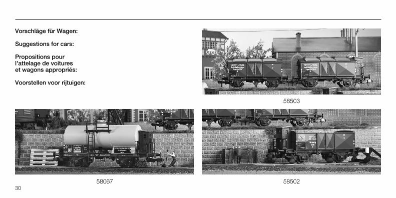
Vorschläge für Wagen:
Suggestions for cars:
Propositions pour l'attelage de voitures et wagons appropriés:
Voorstellen voor rijtuigen:
30
58503
5850258067

This device complies with Part 15 of the FCC Rules. Operation is subject to the following two conditions:(1) This device may not cause harmful interference, and(2) this device must accept any interference received, including
interference that may cause undesired operation.
Gebr. Märklin & Cie. GmbHPostfach 8 60D-73008 Göppingenwww.maerklin.com
651 516 07 04 he naÄnderungen vorbehaltenCopyright byGebr. Märklin & Cie. GmbH


![[English] Samsung PF.pdf · 16--A++ 275 342 101 10 16-A Védjegy B Modell C Kategória 7 (Fagyasztós hűtőszekrény) D Energiahatékonysági osztály ... pe rezultatele pe testul](https://static.fdocuments.fr/doc/165x107/5fe4e6e6d1a4437e18530be6/english-samsung-pfpdf-16-a-275-342-101-10-16-a-vdjegy-b-modell-c-kategria.jpg)