Machine Detector Interface at CEPC - HKUST Jockey Club ...
24
Machine Detector Interface at CEPC Dou Wang, Hongbo Zhu, Huamin Qu, Jianli Wang, Manqi Ruan, Qinglei Xiu, Sha Bai, Shujin Li, Weichao Yao, Yanli Jin, Yin Xu, Yiwei Wang, Yingshun Zhu, Zhongjian Ma Institute of High Energy Physics 23-26 January 2017 HKUST Jockey Club Institute for Advanced Study, Hong Kong 2017/1/25 IAS Program on High Energy Physics 1
Transcript of Machine Detector Interface at CEPC - HKUST Jockey Club ...

Machine Detector Interface at CEPC
Dou Wang, Hongbo Zhu, Huamin Qu, Jianli Wang, Manqi Ruan, Qinglei Xiu, Sha Bai, Shujin Li, Weichao Yao, Yanli Jin, Yin Xu, Yiwei
Wang, Yingshun Zhu, Zhongjian Ma
Institute of High Energy Physics
23-26 January 2017
HKUST Jockey Club Institute for Advanced Study, Hong Kong
2017/1/25 IAS Program on High Energy Physics 1

Outline
• Introduction to MDI • Requirements of the MDI at CEPC • Progresses of sub-projects
– Final focusing magnets – Luminosity measurement – Mechanical support – Beam induced backgrounds
• Summary
2017/1/25 IAS Program on High Energy Physics 2

Machine Detector Interface
• Integration of machine and detector – Global design: confliction between the machine and the detector – Mechanical Support – Shielding
2017/1/25 IAS Program on High Energy Physics 3
Detector Machine
Beam Induced Backgrounds
Luminosity Degrade
Mechanical supporting Shielding . . .
• Mutual influence between the machine and the detector – Luminosity degraded by the detector solenoid field – Beam induced backgrounds – . . .

Requirements of MDI at CEPC
• Requirements of the machine – 𝐿𝐿∗ = 1.5𝑚𝑚 ( 𝑳𝑳∗ ↓ → 𝑳𝑳 ↑) – Compensating solenoid and screening solenoid – Accurate installation and stable mechanical support
• Requirements of the detector – Larger acceptance in polar angle – Lower beam induced backgrounds – Accurate measurement of the luminosity
• Challenges of MDI at CEPC – Many devices will be piled up in IR – Size of devices are limited (Space is very tight)
2017/1/25 IAS Program on High Energy Physics 4
Proposed Layout of IR
• 𝐿𝐿∗ = 1.5𝑚𝑚 • 𝐶𝐶𝐶𝐶𝐶𝐶𝐶𝐶𝐶𝐶𝐶𝐶𝐶𝐶𝐶𝐶 𝑎𝑎𝐶𝐶𝐶𝐶𝑎𝑎𝑎𝑎 = 30 𝑚𝑚𝐶𝐶𝑎𝑎𝑟𝑟 (in the double ring scheme) • QD0
– double aperture superconducting magnet – surrounded by compensating solenoid and screening solenoid
• All forward devices are hoped to be as small as possible 2017/1/25 IAS Program on High Energy Physics 5
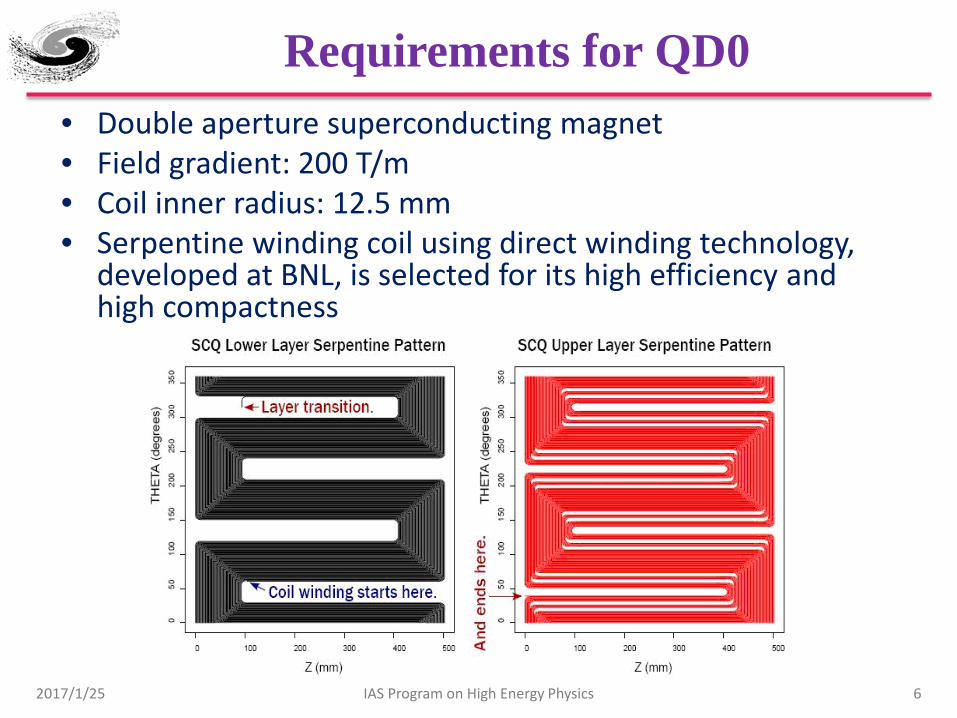
Requirements for QD0 • Double aperture superconducting magnet • Field gradient: 200 T/m • Coil inner radius: 12.5 mm • Serpentine winding coil using direct winding technology,
developed at BNL, is selected for its high efficiency and high compactness
2017/1/25 IAS Program on High Energy Physics 6

Preliminary Design of QD0
• The coils will be made of 0.5mm round NbTi-Cu conductor using direct winding technology.
• Eight Serpentine coil layers are used for the QD0 coil. • The field in one aperture is affected due to the field generated by the coil in
another aperture. • Field cross talk of the two apertures is modelled and studied
2017/1/25 IAS Program on High Energy Physics 7
By Yingshun Zhu

Effect of the Detector Solenoid
• Detector Solenoid → Beam coupling→ 𝑳𝑳 ↓ – Flat beam at CEPC – Coupling between horizontal and
vertical betatron motion will increase the transverse beam size
• To cancel the coupling: ∫ 𝐵𝐵𝑧𝑧𝑟𝑟𝐶𝐶 = 0 – Before quadrupoles: ∫ 𝐵𝐵𝑧𝑧𝑟𝑟𝐶𝐶 = 0
(Compensating solenoid) – Inside quadrupoles: 𝐵𝐵𝑧𝑧 = 0 (Screening
solenoid) • The length of the compensating solenoid is
hoped to be as shorter as possible if the beam stability is satisfied – Designing a 13 T compensating
solenoid with NbTi technology
2017/1/25 IAS Program on High Energy Physics 8
L = 0.7m, B=7.5T
L = 1m, B=5.25T
Detector Solenoid: 3.5T
∫ 𝑩𝑩𝒛𝒛𝒅𝒅𝒅𝒅 = 𝟎𝟎 𝑩𝑩𝒛𝒛 = 𝟎𝟎
Screening solenoid Compensating solenoid
QD0
By Yingshun Zhu, Weichao Yao

Luminosity Calorimeter (LumiCal)
• The uncertainty of luminosity measurement is being studied. • The hardware of the LumiCal hasn’t been studied yet • Space limitation in both radial direction and longitudinal
direction • Geometry will be asymmetric in manufacture and installation
2017/1/25 IAS Program on High Energy Physics 9
𝜃𝜃𝑚𝑚𝑚𝑚𝑚𝑚 𝑍𝑍
𝑐𝑐𝐶𝐶𝐶𝐶𝐶𝐶𝐶𝐶 𝑎𝑎𝐶𝐶𝐶𝐶𝑎𝑎𝑎𝑎= 30𝑚𝑚𝐶𝐶𝑎𝑎𝑟𝑟
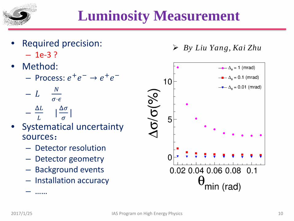
Luminosity Measurement
• Required precision: – 1e-3 ?
• Method: – Process: 𝑎𝑎+𝑎𝑎− → 𝑎𝑎+𝑎𝑎−
– 𝐿𝐿 = 𝑁𝑁𝜎𝜎⋅𝜖𝜖
– Δ𝐿𝐿𝐿𝐿
= | Δ𝜎𝜎𝜎𝜎
| • Systematical uncertainty
sources: – Detector resolution – Detector geometry – Background events – Installation accuracy – ……
2017/1/25 IAS Program on High Energy Physics 10
By Liu Yang, Kai Zhu

Mechanical Support for the Machine
• The support point will be at about 6 m away from the IP – The deformation and vibration might be a problem for the beam
stability • The feasibility of the mechanical support has been preliminary
studied 2017/1/25 IAS Program on High Energy Physics 11
Elements Mass (kg)
LumiCal 130
QD0(Including solenoids) 900
QF1 600
Pump 20
By Shujin Li, Jianli Wang, Huamin Qu

Very Preliminary Results
• The gravity force of accelerator elements are applied to a virtual plane on the support structure
• The deformation at the IP is about 300~400 micron meters • More forces and effects will be considered to improve the
design and simulation 12 2017/1/25 IAS Program on High Energy Physics

Beamstrahlung
Synchrotron Radiation
Beam Induced Backgrounds at CEPC
2017/1/25 IAS Program on High Energy Physics 13
IP1
IP3
Beam Lost Particles Energy Loss > 2%
Radiative Bhabha
50 bunches Revolution frequency: 5475.46 Hz 𝟑𝟑.𝟕𝟕 × 𝟏𝟏𝟎𝟎𝟏𝟏𝟏𝟏 particles/Bunch
L: 𝟐𝟐 × 𝟏𝟏𝟎𝟎𝟑𝟑𝟑𝟑𝒄𝒄𝒄𝒄−𝟐𝟐𝒅𝒅−𝟏𝟏
Beam-Gas Scattering
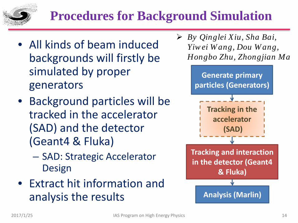
Procedures for Background Simulation
• All kinds of beam induced backgrounds will firstly be simulated by proper generators
• Background particles will be tracked in the accelerator (SAD) and the detector (Geant4 & Fluka) – SAD: Strategic Accelerator
Design • Extract hit information and
analysis the results 2017/1/25 IAS Program on High Energy Physics 14
Generate primary particles (Generators)
Tracking and interaction in the detector (Geant4
& Fluka)
Analysis (Marlin)
Tracking in the accelerator
(SAD)
By Qinglei Xiu, Sha Bai, Yiwei Wang, Dou Wang, Hongbo Zhu, Zhongjian Ma
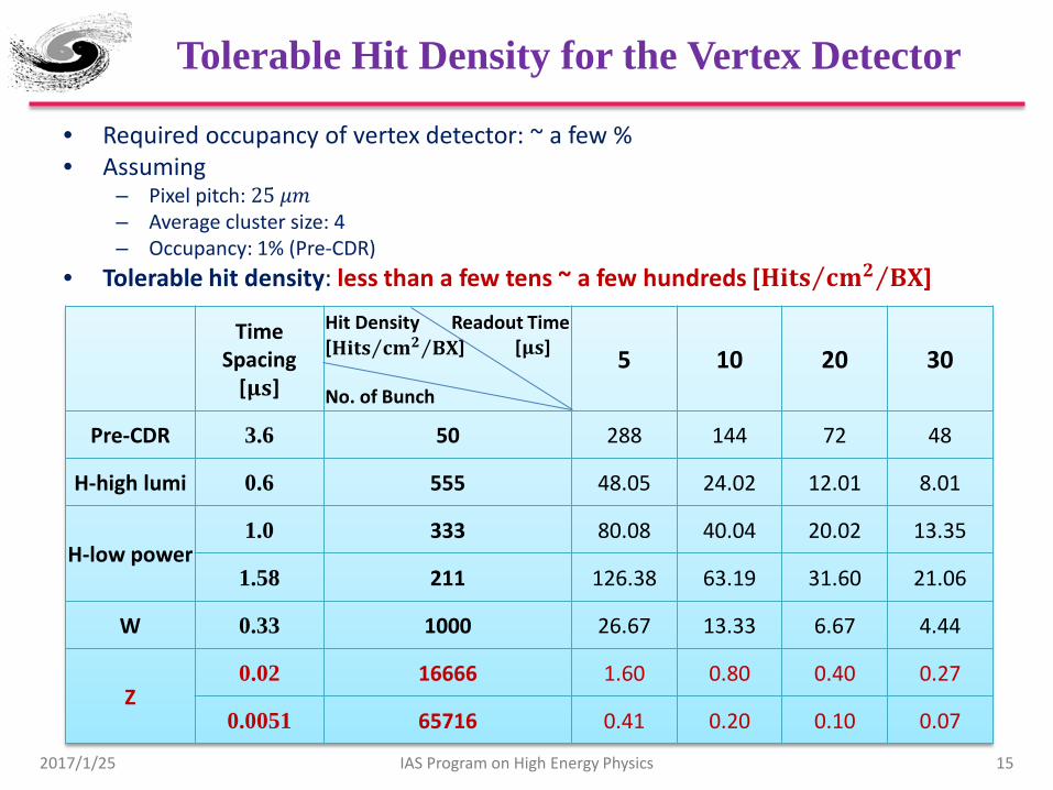
Tolerable Hit Density for the Vertex Detector
• Required occupancy of vertex detector: ~ a few % • Assuming
– Pixel pitch: 25 𝜇𝜇𝑚𝑚 – Average cluster size: 4 – Occupancy: 1% (Pre-CDR)
• Tolerable hit density: less than a few tens ~ a few hundreds [𝐇𝐇𝐇𝐇𝐇𝐇𝐇𝐇 𝐜𝐜𝐜𝐜𝟐𝟐 𝐁𝐁𝐁𝐁⁄⁄ ]
2017/1/25 IAS Program on High Energy Physics 15
Time Spacing
[𝛍𝛍𝐇𝐇]
Hit Density Readout Time [𝐇𝐇𝐇𝐇𝐇𝐇𝐇𝐇 𝐜𝐜𝐜𝐜𝟐𝟐 𝐁𝐁𝐁𝐁⁄⁄ ] [𝛍𝛍𝐇𝐇] No. of Bunch
5 10 20 30
Pre-CDR 3.6 50 288 144 72 48
H-high lumi 0.6 555 48.05 24.02 12.01 8.01
H-low power 1.0 333 80.08 40.04 20.02 13.35
1.58 211 126.38 63.19 31.60 21.06
W 0.33 1000 26.67 13.33 6.67 4.44
Z 0.02 16666 1.60 0.80 0.40 0.27
0.0051 65716 0.41 0.20 0.10 0.07

Backgrounds Level of Single Ring Scheme
Background type Simulation software Sub-type Particle flux at
VTX [𝒄𝒄𝒄𝒄−𝟐𝟐𝑩𝑩𝑩𝑩−𝟏𝟏 ] Particle energy
[GeV] Priority
Synchrotron radiation
Geant4; BDSIM
Dipole ~ 𝟏𝟏𝟎𝟎𝟏𝟏𝟎𝟎 ~ 0.001 ★★★
Quadrupole ~ 𝟏𝟏𝟎𝟎𝟔𝟔 ~ 0.007
Beam lost particles
BBBrem; SAD
Radiative Bhabha ~ 10 ~ 120
★★ Beam Gas Scattering ↑ ↑
Beamstrahlung Guinea-Pig++; PYTHIA6
Pairs ~ 𝟏𝟏𝟎𝟎−𝟐𝟐 ~ 0.05 ★
Hadrons ~ 𝟏𝟏𝟎𝟎−𝟓𝟓 ~ 2
2017/1/25 IAS Program on High Energy Physics 16
• Backgrounds level of the single ring scheme without shielding – A very preliminary version of machine lattice – The synchrotron radiation level is too high
• To suppress the background level – Insert shielding and collimator – Improve the machine design to reduce the SR power at IR
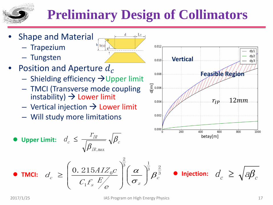
Preliminary Design of Collimators • Shape and Material
– Trapezium – Tungsten
• Position and Aperture 𝑟𝑟𝑐𝑐 – Shielding efficiency Upper limit – TMCI (Transverse mode coupling
instability) Lower limit – Vertical injection Lower limit – Will study more limitations
c
IR
IRc
rd β
β max,
≤ Upper Limit:
cc ad β≥ Injection: 3
23
13
2
1
0215.0c
zs
c
eEfC
cAIZd β
σα
≥ TMCI:
2017/1/25 IAS Program on High Energy Physics 17
Feasible Region
Vertical
𝐶𝐶𝐼𝐼𝐼𝐼 = 12𝑚𝑚𝑚𝑚

Synchrotron Radiation from the Last Dipole
• The synchrotron radiation are generated and simulated by the model embedded in Geant4
• Collimators for synchrotron radiation from dipole are designed – Material: Tungsten – Thickness: 10 cm
• The synchrotron radiation can be suppressed by the factor of 𝟏𝟏𝟎𝟎𝟑𝟑 – Critical energy: ~ 1 MeV
2017/1/25 IAS Program on High Energy Physics 18

Lost Particles (Radiative Bhabha)
• Energy acceptance: 2% • Tracking particles with SAD (Strategic Accelerator
Design) • Add collimators to stop lost particles before they enter
the IR
19 2017/1/25 IAS Program on High Energy Physics

Beamstrahlung
• Characterized by: Υ = 56
𝑁𝑁𝑟𝑟𝑒𝑒2𝛾𝛾𝛼𝛼(𝜎𝜎𝑥𝑥+𝜎𝜎𝑦𝑦)𝜎𝜎𝑧𝑧
• The effects of beamstrahlung at CEPC should be much smaller than ILC
• Secondary particles of beamstrahlung are generated by Guinea-Pig++
Symbol LEP2 CEPC ILC 250GeV
Ecm [GeV] 209 240 250
N [× 1010] 58 37.1 2
𝜎𝜎𝑥𝑥 / 𝜎𝜎𝑦𝑦 [𝐶𝐶𝑚𝑚] 270000/3500
73700 / 160 729 / 7.7
𝜎𝜎𝑧𝑧 [𝜇𝜇𝑚𝑚] 16000 2260 300
𝛽𝛽𝑥𝑥 / 𝛽𝛽𝑦𝑦 [𝑚𝑚𝑚𝑚] 1500/50 800 / 1.2 13 / 0.41
𝛾𝛾𝛾𝛾𝑥𝑥 / 𝛾𝛾𝛾𝛾𝑦𝑦 [𝑚𝑚𝑚𝑚 ∙ 𝑚𝑚𝐶𝐶𝑎𝑎𝑟𝑟]
9.81/0.051 1594.5 / 4.79 10 / 0.035
𝚼𝚼 2.5e-5 4.7e-4 0.02
20 2017/1/25 IAS Program on High Energy Physics
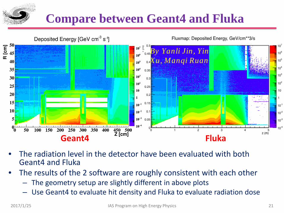
Compare between Geant4 and Fluka
• The radiation level in the detector have been evaluated with both Geant4 and Fluka
• The results of the 2 software are roughly consistent with each other – The geometry setup are slightly different in above plots – Use Geant4 to evaluate hit density and Fluka to evaluate radiation dose
Geant4 Fluka
2017/1/25 IAS Program on High Energy Physics 21
By Yanli Jin, Yin Xu, Manqi Ruan

Improve the Lattice Design of IR
• The synchrotron radiation has been considered in the IR design of double ring scheme
• Weaker dipoles at the upstream of IR to reduced the synchrotron radiation power
• The backscattered backgrounds at the downstream need be carefully evaluated
2017/1/25 IAS Program on High Energy Physics 22

Summary
2017/1/25 IAS Program on High Energy Physics 23
• The mutual influences between machine and detector have been evaluated. – The L* of CEPC is set as 1.5 m to achieve the required
luminosity. – The compensating solenoid and the screening solenoid are
designed to shielding the detector solenoid field – Beam induced backgrounds of CEPC have been evaluated.
Useful software and tools were developed – The error of luminosity measurement has been studied
• The mechanical support has been preliminary studied • The shielding and collimators need be further studied. • The beam pipe and hardware of LumiCal haven’t been
studied
Thanks
2017/1/25 IAS Program on High Energy Physics 24