M2-Internet 1-1 Protocoles et services internet Sommaire (prévision): Introduction et rappels...
83
M2-Internet 1-1 Protocoles et services internet Sommaire (prévision): Introduction et rappels réseau Rappels java Quelques compléments java Protocoles: couche application Html-http ftp smtp dns Réseaux Pair à pair Sécurité, sockets ssl Serveurs web Apache, servlet, web services Wireless 3 séances de TP + examen H. Fauconnier
-
Upload
amos-caldwell -
Category
Documents
-
view
215 -
download
1
Transcript of M2-Internet 1-1 Protocoles et services internet Sommaire (prévision): Introduction et rappels...
M2-Internet 1-1
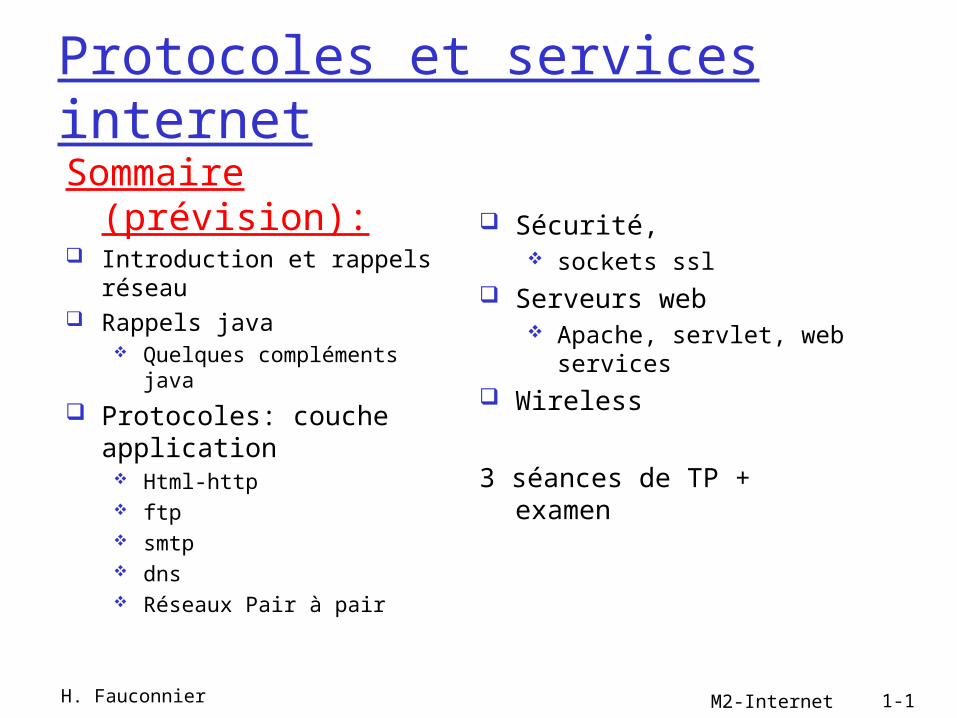
Protocoles et services internetSommaire
(prévision): Introduction et rappels
réseau Rappels java
Quelques compléments java
Protocoles: couche application
Html-http ftp smtp dns Réseaux Pair à pair
Sécurité, sockets ssl
Serveurs web Apache, servlet, web
services Wireless
3 séances de TP + examen
H. Fauconnier

Bibliographie
Java Network Programming, 3rd Edition Elliotte Rusty Harold O'Reilly Media, Inc..
Computer networking J.F. Kurose K.W. Ross Addison Wesley.
M2-Internet 1-2H. Fauconnier

Chapitre 1
Introduction (rappels réseau) Hôtes, réseaux d’accès, liens physiques Commutation par circuits, par paquets,
structure du réseau Pertes et délais Protocoles et modèle en couches Sécurité Historique…
H. Fauconnier M2-Internet 1-3

M2-Internet Introduction 1-4
Les composants…
millions of connected computing devices: hosts = end systems running network
apps Home network
Institutional network
Mobile network
Global ISP
Regional ISP
router
PC
server
wirelesslaptop
cellular handheld
wiredlinks
access points
communication links fiber, copper,
radio, satellite transmission
rate = bandwidth
routers: forward packets (chunks of data)
H. Fauconnier
M2-Internet Introduction 1-5
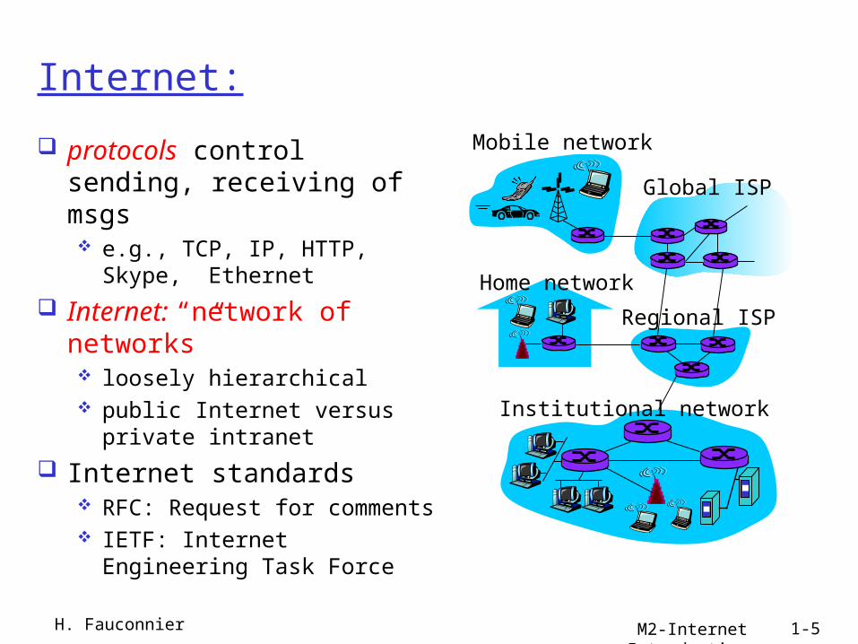
Internet:
protocols control sending, receiving of msgs e.g., TCP, IP, HTTP, Skype,
Ethernet
Internet: “network of networks” loosely hierarchical public Internet versus
private intranet
Internet standards RFC: Request for comments IETF: Internet Engineering
Task Force
Home network
Institutional network
Mobile network
Global ISP
Regional ISP
H. Fauconnier
M2-Internet Introduction 1-6
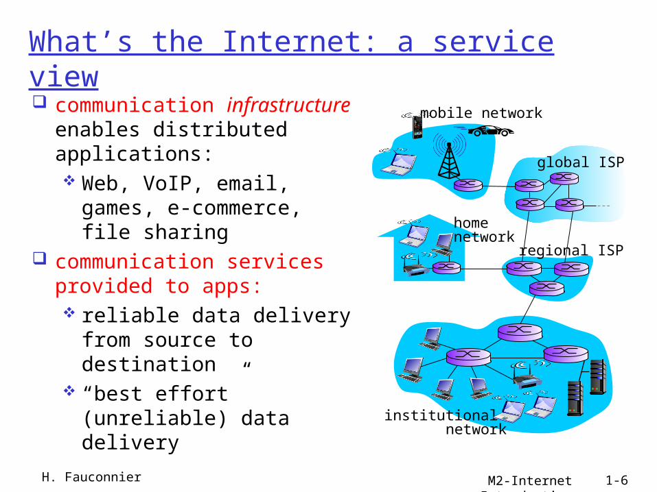
What’s the Internet: a service view communication
infrastructure enables distributed applications: Web, VoIP, email, games,
e-commerce, file sharing communication services
provided to apps: reliable data delivery
from source to destination
“best effort” (unreliable) data delivery
H. Fauconnier
mobile network
global ISP
regional ISP
home network
institutional network

M2-Internet Introduction 1-7
A closer look at network structure:
network edge: applications and hosts
access networks, physical media: wired, wireless communication links network core: interconnected
routers network of
networksH. Fauconnier
mobile network
global ISP
regional ISP
home network
institutional network

M2-Internet Introduction 1-8
The network edge: end systems (hosts):
run application programs e.g. Web, email at “edge of network”
client/server
peer-peer
client/server model client host requests,
receives service from always-on server
e.g. Web browser/server; email client/server peer-peer model:
minimal (or no) use of dedicated servers
e.g. Skype, BitTorrent
H. Fauconnier

M2-Internet Introduction 1-9
Types d’accès
residential access nets institutional access
networks (school, company)
mobile access networks
Keep in mind: bandwidth (bits per
second) of access network?
shared or dedicated?H. Fauconnier
mobile network
global ISP
regional ISP
home network
institutional network
Introduction
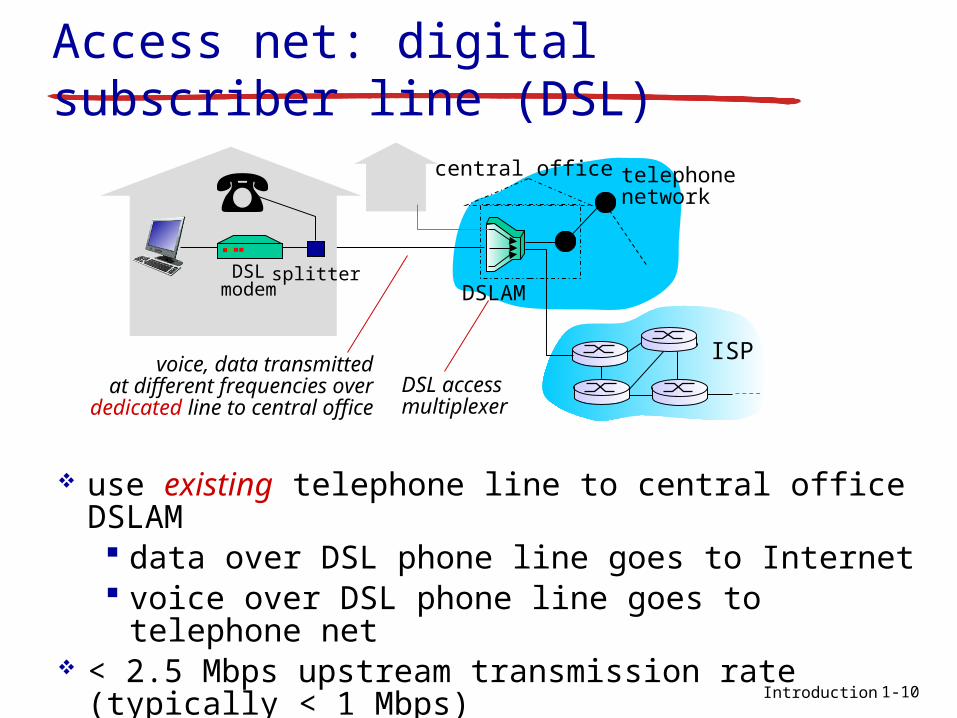
Access net: digital subscriber line (DSL)
central office
ISP
telephonenetwork
DSLAM
voice, data transmittedat different frequencies over
dedicated line to central office
use existing telephone line to central office DSLAM data over DSL phone line goes to Internet voice over DSL phone line goes to telephone net
< 2.5 Mbps upstream transmission rate (typically < 1 Mbps)
< 24 Mbps downstream transmission rate (typically < 10 Mbps)
DSLmodem
splitter
DSL access multiplexer
1-10
Introduction
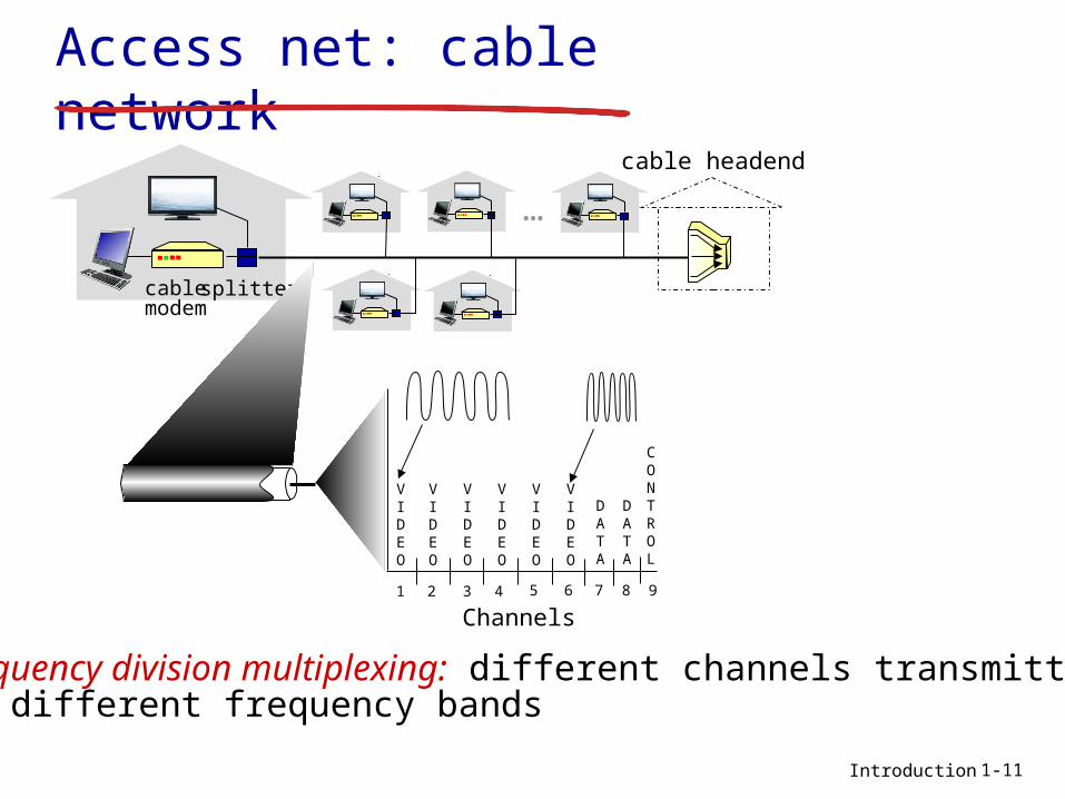
Access net: cable network
cablemodem
splitter
…
cable headend
Channels
VIDEO
VIDEO
VIDEO
VIDEO
VIDEO
VIDEO
DATA
DATA
CONTROL
1 2 3 4 5 6 7 8 9
frequency division multiplexing: different channels transmittedin different frequency bands
1-11
Introduction
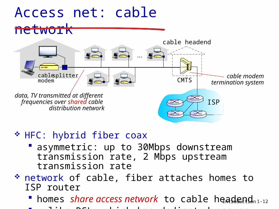
data, TV transmitted at different frequencies over shared cable
distribution network
cablemodem
splitter
…
cable headend
CMTS
ISP
cable modemtermination system
HFC: hybrid fiber coax asymmetric: up to 30Mbps downstream
transmission rate, 2 Mbps upstream transmission rate
network of cable, fiber attaches homes to ISP router homes share access network to cable headend unlike DSL, which has dedicated access to
central office
Access net: cable network
1-12

Introduction
Access net: home network
to/from headend or central office
cable or DSL modem
router, firewall, NAT
wired Ethernet (100 Mbps)
wireless access point (54 Mbps)
wirelessdevices
often combined in single box
1-13
Introduction
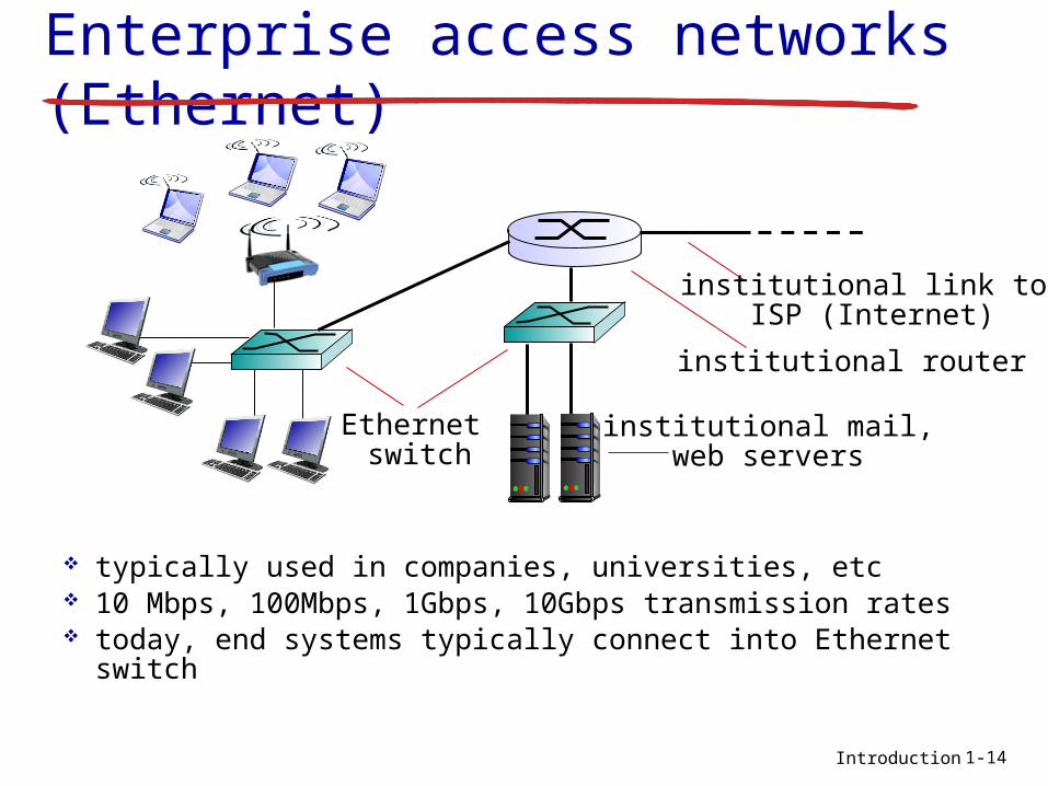
Enterprise access networks (Ethernet)
typically used in companies, universities, etc 10 Mbps, 100Mbps, 1Gbps, 10Gbps transmission rates today, end systems typically connect into Ethernet
switch
Ethernet switch
institutional mail,web servers
institutional router
institutional link to ISP (Internet)
1-14

Introduction
Wireless access networks
shared wireless access network connects end system to router via base station aka “access point”
wireless LANs: within building (100 ft) 802.11b/g (WiFi): 11, 54
Mbps transmission rate
wide-area wireless access provided by telco (cellular)
operator, 10’s km between 1 and 10 Mbps 3G, 4G: LTE
to Internet
to Internet
1-15
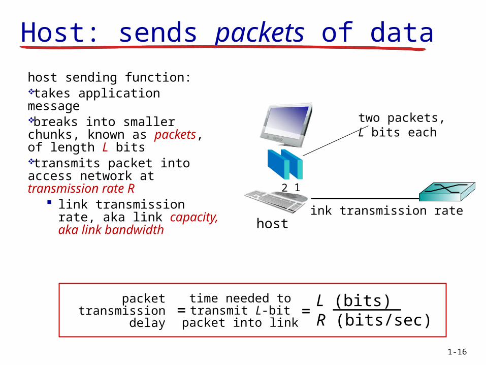
Host: sends packets of data
host sending function:takes application messagebreaks into smaller chunks, known as packets, of length L bitstransmits packet into access network at transmission rate R
link transmission rate, aka link capacity, aka link bandwidth
R: link transmission ratehost
12
two packets, L bits each
packettransmission
delay
time needed totransmit L-bit
packet into link
L (bits)R (bits/sec)
= =
1-16

M2-Internet Introduction 1-17
Physical Media
Bit: propagates betweentransmitter/rcvr pairs
physical link: what lies between transmitter & receiver
guided media: signals propagate in solid
media: copper, fiber, coax
unguided media: signals propagate freely,
e.g., radio
Twisted Pair (TP) two insulated copper
wires Category 3: traditional
phone wires, 10 Mbps Ethernet
Category 5: 100Mbps Ethernet
H. Fauconnier
M2-Internet Introduction 1-18
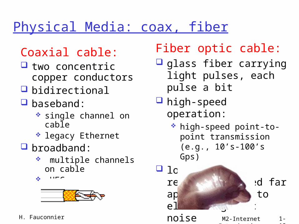
Physical Media: coax, fiber
Coaxial cable: two concentric copper
conductors bidirectional baseband:
single channel on cable legacy Ethernet
broadband: multiple channels on
cable HFC
Fiber optic cable: glass fiber carrying
light pulses, each pulse a bit
high-speed operation: high-speed point-to-point
transmission (e.g., 10’s-100’s Gps)
low error rate: repeaters spaced far apart ; immune to electromagnetic noise
H. Fauconnier
M2-Internet Introduction 1-19
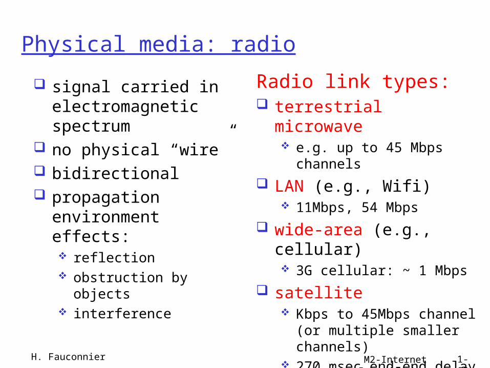
Physical media: radio
signal carried in electromagnetic spectrum
no physical “wire” bidirectional propagation
environment effects: reflection obstruction by objects interference
Radio link types: terrestrial microwave
e.g. up to 45 Mbps channels
LAN (e.g., Wifi) 11Mbps, 54 Mbps
wide-area (e.g., cellular) 3G cellular: ~ 1 Mbps
satellite Kbps to 45Mbps channel
(or multiple smaller channels)
270 msec end-end delay geosynchronous versus low
altitudeH. Fauconnier
Commutation par paquets- par circuits?
H. Fauconnier M2-Internet 1-20
Introduction
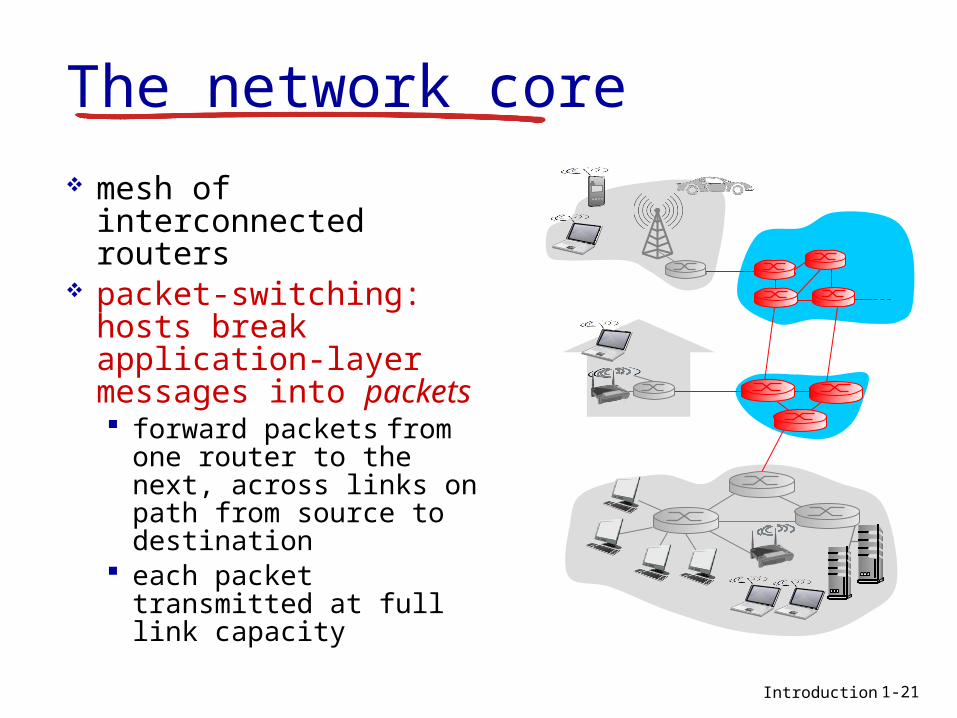
mesh of interconnected routers
packet-switching: hosts break application-layer messages into packets forward packets from
one router to the next, across links on path from source to destination
each packet transmitted at full link capacity
The network core
1-21

Introduction
Packet-switching: store-and-forward
takes L/R seconds to transmit (push out) L-bit packet into link at R bps
store and forward: entire packet must arrive at router before it can be transmitted on next link
one-hop numerical example:
L = 7.5 Mbits R = 1.5 Mbps one-hop transmission
delay = 5 sec
more on delay shortly …1-22
sourceR bps destination
123
L bitsper packet
R bps
end-end delay = 2L/R (assuming zero propagation delay)

Introduction
Packet Switching: queueing delay, loss
A
B
CR = 100 Mb/s
R = 1.5 Mb/sD
Equeue of packetswaiting for output link
1-23
queuing and loss: If arrival rate (in bits) to link exceeds
transmission rate of link for a period of time: packets will queue, wait to be transmitted on
link packets can be dropped (lost) if memory
(buffer) fills up
Network Layer 4-24
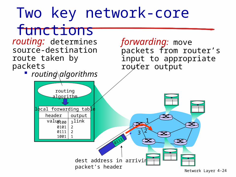
Two key network-core functions
forwarding: move packets from router’s input to appropriate router output
routing: determines source-destination route taken by packets
routing algorithms
routing algorithm
local forwarding tableheader value output link
0100010101111001
3221
1
23
0111
dest address in arrivingpacket’s header
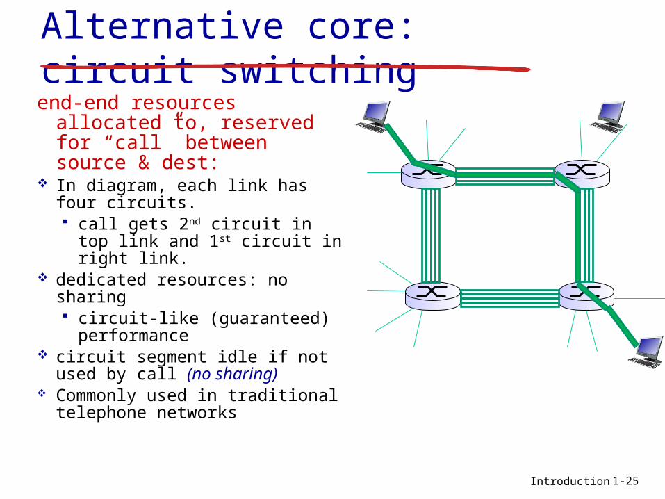
Introduction
Alternative core: circuit switchingend-end resources allocated
to, reserved for “call” between source & dest:
In diagram, each link has four circuits. call gets 2nd circuit in top
link and 1st circuit in right link.
dedicated resources: no sharing circuit-like (guaranteed)
performance circuit segment idle if not
used by call (no sharing) Commonly used in traditional
telephone networks
1-25
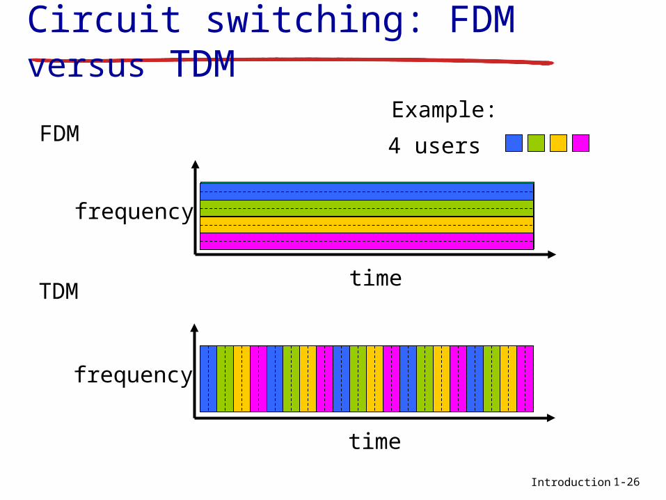
Introduction
Circuit switching: FDM versus TDM
FDM
frequency
timeTDM
frequency
time
4 users
Example:
1-26
Introduction
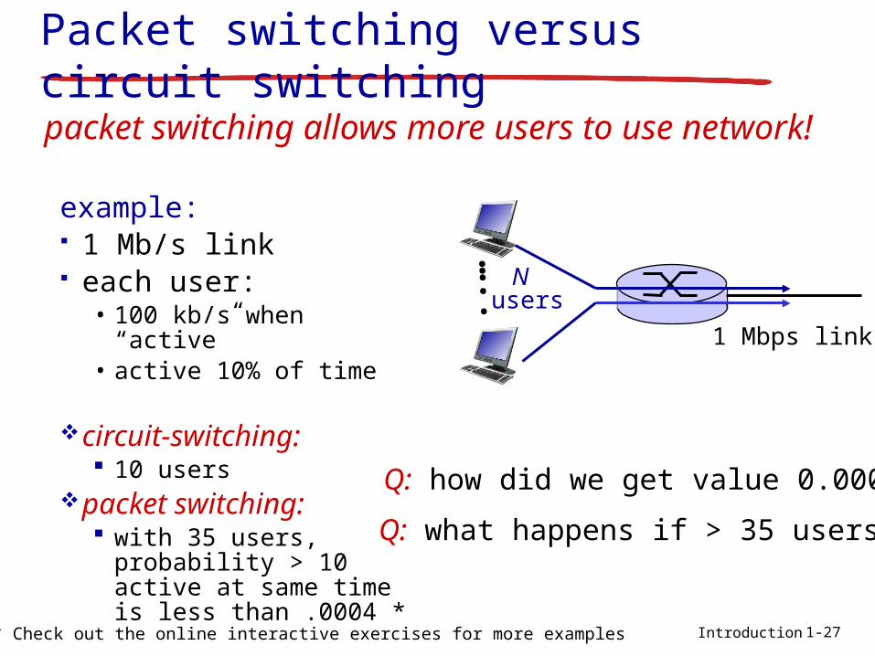
Packet switching versus circuit switching
example: 1 Mb/s link each user:
• 100 kb/s when “active”• active 10% of time
circuit-switching: 10 users
packet switching: with 35 users,
probability > 10 active at same time is less than .0004 *
packet switching allows more users to use network!
N users
1 Mbps link
Q: how did we get value 0.0004?
Q: what happens if > 35 users ?
…..
1-27* Check out the online interactive exercises for more examples
Introduction
great for bursty data resource sharing simpler, no call setup
excessive congestion possible: packet delay and loss protocols needed for reliable data transfer,
congestion control Q: How to provide circuit-like behavior?
bandwidth guarantees needed for audio/video apps
still an unsolved problem
is packet switching a “slam dunk winner?”
Q: human analogies of reserved resources (circuit switching) versus on-demand allocation (packet-switching)?
Packet switching versus circuit switching
1-28

Internet structure: network of networks
Question: given millions of access ISPs, how to connect them together?
accessnet
accessnet
accessnet
accessnet
accessnet
accessnet
accessnet
accessnet
accessnet
accessnet
accessnet
accessnet
accessnet
accessnetaccess
net
accessnet
…
………
…
…
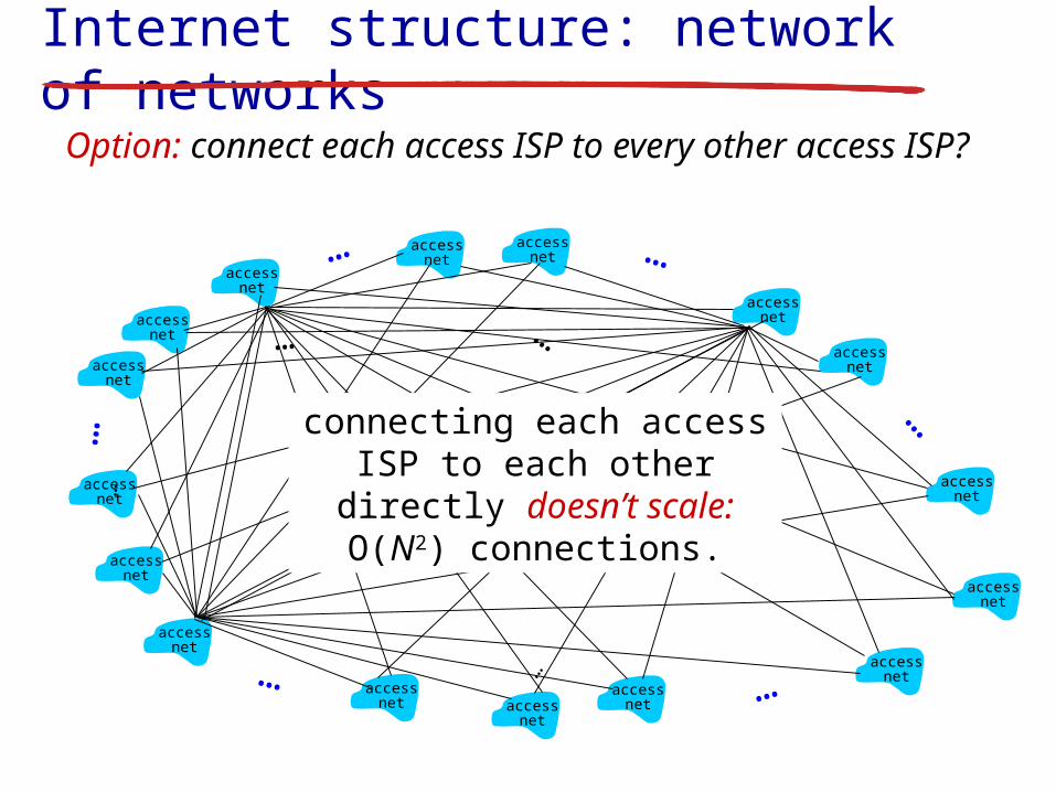
Internet structure: network of networks
Option: connect each access ISP to every other access ISP?
accessnet
accessnet
accessnet
accessnet
accessnet
accessnet
accessnet
accessnet
accessnet
accessnet
accessnet
accessnet
accessnet
accessnetaccess
net
accessnet
…
………
…
…
…
…
………
connecting each access ISP to each other directly doesn’t
scale: O(N2) connections.

Internet structure: network of networks
accessnet
accessnet
accessnet
accessnet
accessnet
accessnet
accessnet
accessnet
accessnet
accessnet
accessnet
accessnet
accessnet
accessnetaccess
net
accessnet
…
………
…
…
Option: connect each access ISP to a global transit ISP? Customer and provider ISPs have economic agreement.
globalISP

Internet structure: network of networks
accessnet
accessnet
accessnet
accessnet
accessnet
accessnet
accessnet
accessnet
accessnet
accessnet
accessnet
accessnet
accessnet
accessnetaccess
net
accessnet
…
………
…
…
But if one global ISP is viable business, there will be competitors ….
ISP B
ISP A
ISP C
Internet structure: network of networks
accessnet
accessnet
accessnet
accessnet
accessnet
accessnet
accessnet
accessnet
accessnet
accessnet
accessnet
accessnet
accessnet
accessnetaccess
net
accessnet
…
………
…
…
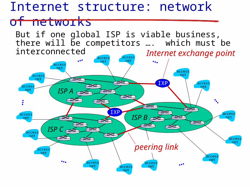
But if one global ISP is viable business, there will be competitors …. which must be interconnected
ISP B
ISP A
ISP C
IXP
IXP
peering link
Internet exchange point

Internet structure: network of networks
accessnet
accessnet
accessnet
accessnet
accessnet
accessnet
accessnet
accessnet
accessnet
accessnet
accessnet
accessnet
accessnet
accessnetaccess
net
accessnet
…
………
…
…
… and regional networks may arise to connect access nets to ISPS
ISP B
ISP A
ISP C
IXP
IXP
regional net

Internet structure: network of networks
accessnet
accessnet
accessnet
accessnet
accessnet
accessnet
accessnet
accessnet
accessnet
accessnet
accessnet
accessnet
accessnet
accessnetaccess
net
accessnet
…
………
…
…
… and content provider networks (e.g., Google, Microsoft, Akamai ) may run their own network, to bring services, content close to end users
ISP B
ISP A
ISP B
IXP
IXP
regional net
Content provider network
Introduction
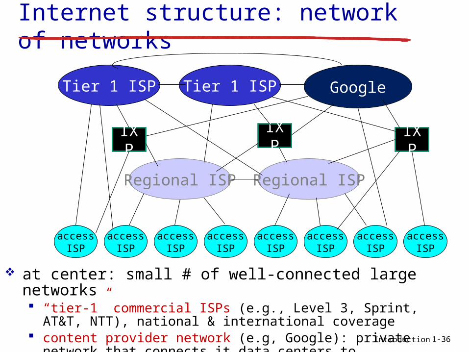
Internet structure: network of networks
at center: small # of well-connected large networks “tier-1” commercial ISPs (e.g., Level 3, Sprint, AT&T, NTT),
national & international coverage content provider network (e.g, Google): private network
that connects it data centers to Internet, often bypassing tier-1, regional ISPs
1-36
accessISP
accessISP
accessISP
accessISP
accessISP
accessISP
accessISP
accessISP
Regional ISP Regional ISP
IXP
IXP
Tier 1 ISP Tier 1 ISP Google
IXP
M2-Internet Introduction 1-37
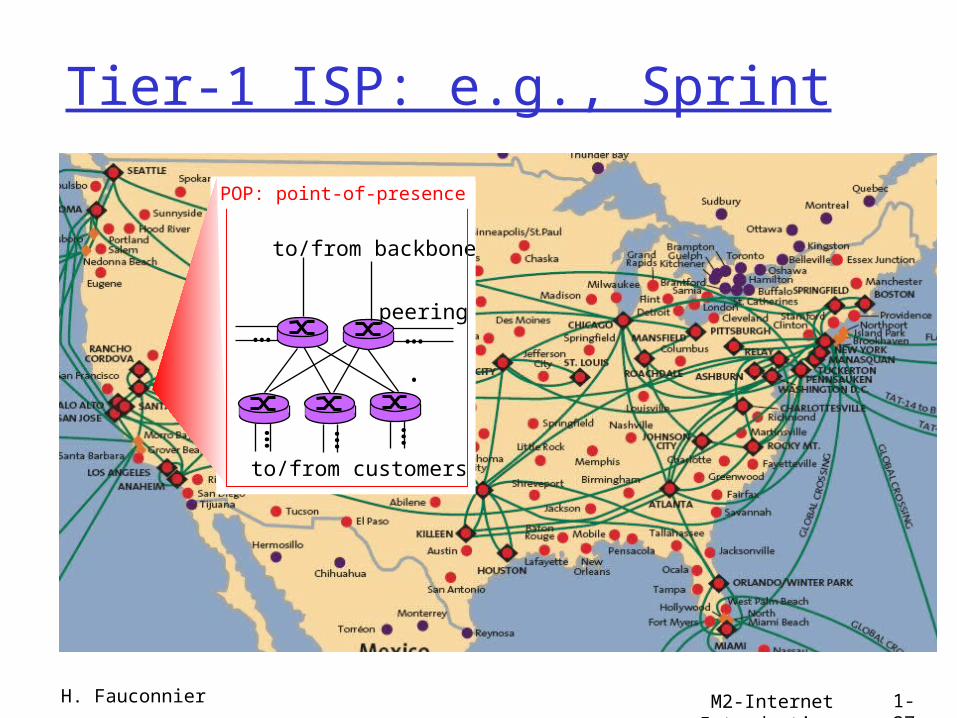
Tier-1 ISP: e.g., Sprint
…
to/from customers
peering
to/from backbone
….
………
POP: point-of-presence
H. Fauconnier

M2-Internet Introduction 1-38
Internet structure: network of networks
“Tier-2” ISPs: smaller (often regional) ISPs Connect to one or more tier-1 ISPs, possibly other tier-2 ISPs
Tier 1 ISP
Tier 1 ISP
Tier 1 ISP
Tier-2 ISPTier-2 ISP
Tier-2 ISP Tier-2 ISP
Tier-2 ISP
Tier-2 ISP pays tier-1 ISP for connectivity to rest of Internet tier-2 ISP is customer oftier-1 provider
Tier-2 ISPs also peer privately with each other.
H. Fauconnier
M2-Internet Introduction 1-39
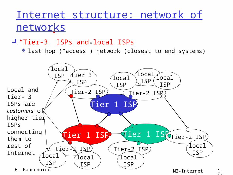
Internet structure: network of networks
“Tier-3” ISPs and local ISPs last hop (“access”) network (closest to end systems)
Tier 1 ISP
Tier 1 ISP
Tier 1 ISP
Tier-2 ISPTier-2 ISP
Tier-2 ISP Tier-2 ISP
Tier-2 ISP
localISPlocal
ISPlocalISP
localISP
localISP Tier 3
ISP
localISP
localISP
localISP
Local and tier- 3 ISPs are customers ofhigher tier ISPsconnecting them to rest of Internet
H. Fauconnier
M2-Internet Introduction 1-40
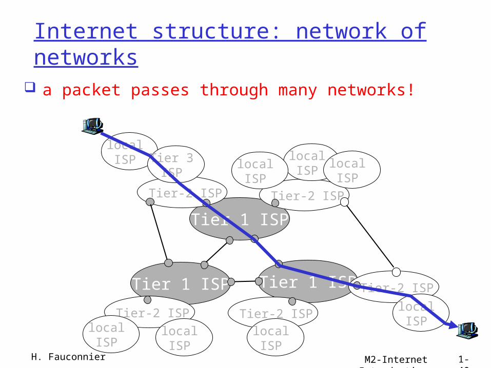
Internet structure: network of networks
a packet passes through many networks!
Tier 1 ISP
Tier 1 ISP
Tier 1 ISP
Tier-2 ISPTier-2 ISP
Tier-2 ISP Tier-2 ISP
Tier-2 ISP
localISPlocal
ISPlocalISP
localISP
localISP Tier 3
ISP
localISP
localISP
localISP
H. Fauconnier

M2-Internet Introduction 1-41
Délais et pertes..
H. Fauconnier
Introduction
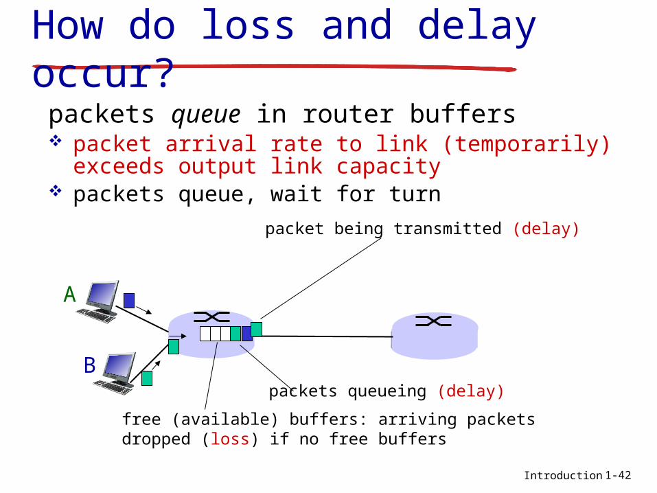
How do loss and delay occur?
packets queue in router buffers packet arrival rate to link (temporarily) exceeds
output link capacity packets queue, wait for turn
A
B
packet being transmitted (delay)
packets queueing (delay)
free (available) buffers: arriving packets dropped (loss) if no free buffers
1-42
Introduction
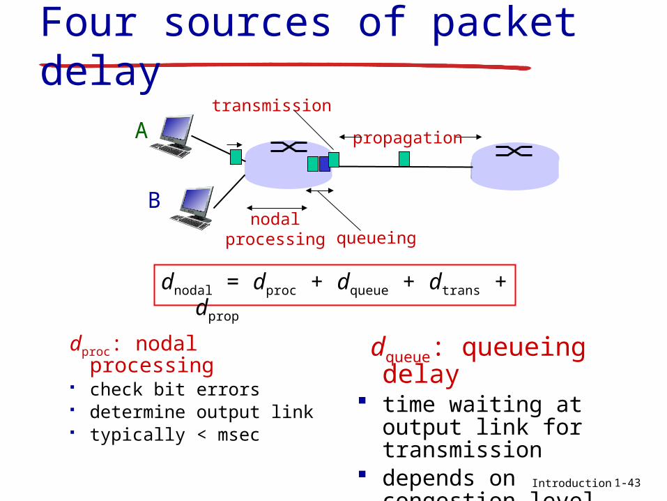
Four sources of packet delay
dproc: nodal processing check bit errors determine output link typically < msec
A
B
propagation
transmission
nodalprocessing queueing
dqueue: queueing delay
time waiting at output link for transmission
depends on congestion level of router
dnodal = dproc + dqueue + dtrans + dprop
1-43

Introduction
dtrans: transmission delay:
L: packet length (bits) R: link bandwidth (bps) dtrans = L/R
dprop: propagation delay: d: length of physical link s: propagation speed in
medium (~2x10⁸ m/sec) dprop = d/sdtrans and dprop
very different
Four sources of packet delay
propagation
nodalprocessing queueing
dnodal = dproc + dqueue + dtrans + dprop
1-44
A
B
transmission
* Check out the Java applet for an interactive animation on trans vs. prop delay

Introduction
Caravan analogy
cars “propagate” at 100 km/hr
toll booth takes 12 sec to service car (bit transmission time)
car~bit; caravan ~ packet
Q: How long until caravan is lined up before 2nd toll booth?
time to “push” entire caravan through toll booth onto highway = 12*10 = 120 sec
time for last car to propagate from 1st to 2nd toll both: 100km/(100km/hr)= 1 hr
A: 62 minutes
toll booth
toll booth
ten-car caravan
100 km 100 km
1-45
Introduction
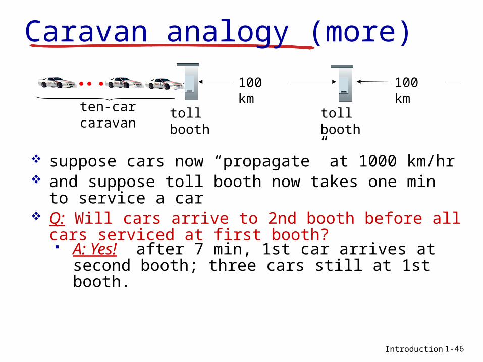
Caravan analogy (more)
suppose cars now “propagate” at 1000 km/hr and suppose toll booth now takes one min to
service a car Q: Will cars arrive to 2nd booth before all cars
serviced at first booth? A: Yes! after 7 min, 1st car arrives at second
booth; three cars still at 1st booth.
toll booth
toll booth
ten-car caravan
100 km 100 km
1-46

Introduction
R: link bandwidth (bps) L: packet length (bits) a: average packet
arrival rate
traffic intensity = La/R
La/R ~ 0: avg. queueing delay small La/R -> 1: avg. queueing delay large La/R > 1: more “work” arriving than can be serviced, average delay
infinite!
ave
rage
qu
eue
ing
d
ela
y
La/R ~ 0
Queueing delay (revisited)
La/R -> 11-47
* Check out the Java applet for an interactive animation on queuing and loss

Introduction
“Real” Internet delays and routes
what do “real” Internet delay & loss look like? traceroute program: provides delay
measurement from source to router along end-end Internet path towards destination. For all i: sends three packets that will reach router i on path
towards destination router i will return packets to sender sender times interval between transmission and reply.
3 probes
3 probes
3 probes
1-48

Introduction
“Real” Internet delays, routes
1 cs-gw (128.119.240.254) 1 ms 1 ms 2 ms2 border1-rt-fa5-1-0.gw.umass.edu (128.119.3.145) 1 ms 1 ms 2 ms3 cht-vbns.gw.umass.edu (128.119.3.130) 6 ms 5 ms 5 ms4 jn1-at1-0-0-19.wor.vbns.net (204.147.132.129) 16 ms 11 ms 13 ms 5 jn1-so7-0-0-0.wae.vbns.net (204.147.136.136) 21 ms 18 ms 18 ms 6 abilene-vbns.abilene.ucaid.edu (198.32.11.9) 22 ms 18 ms 22 ms7 nycm-wash.abilene.ucaid.edu (198.32.8.46) 22 ms 22 ms 22 ms8 62.40.103.253 (62.40.103.253) 104 ms 109 ms 106 ms9 de2-1.de1.de.geant.net (62.40.96.129) 109 ms 102 ms 104 ms10 de.fr1.fr.geant.net (62.40.96.50) 113 ms 121 ms 114 ms11 renater-gw.fr1.fr.geant.net (62.40.103.54) 112 ms 114 ms 112 ms12 nio-n2.cssi.renater.fr (193.51.206.13) 111 ms 114 ms 116 ms13 nice.cssi.renater.fr (195.220.98.102) 123 ms 125 ms 124 ms14 r3t2-nice.cssi.renater.fr (195.220.98.110) 126 ms 126 ms 124 ms15 eurecom-valbonne.r3t2.ft.net (193.48.50.54) 135 ms 128 ms 133 ms16 194.214.211.25 (194.214.211.25) 126 ms 128 ms 126 ms17 * * *18 * * *19 fantasia.eurecom.fr (193.55.113.142) 132 ms 128 ms 136 ms
traceroute: gaia.cs.umass.edu to www.eurecom.fr
3 delay measurements from gaia.cs.umass.edu to cs-gw.cs.umass.edu
* means no response (probe lost, router not replying)
trans-oceaniclink
1-49* Do some traceroutes from exotic countries at www.traceroute.org

Introduction
Packet loss queue (aka buffer) preceding link in buffer
has finite capacity packet arriving to full queue dropped (aka
lost) lost packet may be retransmitted by
previous node, by source end system, or not at all
A
B
packet being transmitted
packet arriving tofull buffer is lost
buffer (waiting area)
1-50* Check out the Java applet for an interactive animation on queuing and loss

Introduction
Throughput throughput: rate (bits/time unit) at which
bits transferred between sender/receiver instantaneous: rate at given point in time average: rate over longer period of time
server, withfile of F bits
to send to client
link capacity
Rs bits/sec
link capacity
Rc bits/secserver sends
bits (fluid) into pipe
pipe that can carryfluid at rate
Rs bits/sec)
pipe that can carryfluid at rate
Rc bits/sec)
1-51

Introduction
Throughput (more) Rs < Rc What is average end-end throughput?
Rs bits/sec Rc bits/sec
Rs > Rc What is average end-end throughput?
link on end-end path that constrains end-end throughput
bottleneck link
Rs bits/sec Rc bits/sec
1-52

Introduction
Throughput: Internet scenario
10 connections (fairly) share backbone bottleneck link R bits/sec
Rs
Rs
Rs
Rc
Rc
Rc
R
per-connection end-end throughput: min(Rc,Rs,R/10)
in practice: Rc or Rs is often bottleneck
1-53

M2-Internet Introduction 1-54
Protocoles, modèle en couches
H. Fauconnier
M2-Internet Introduction 1-55
Protocol “Layers”Networks are
complex! many “pieces”:
hosts routers links of various
media applications protocols hardware,
software
Question: Is there any hope of organizing structure of
network?
Or at least our discussion of networks?
H. Fauconnier

M2-Internet Introduction 1-56
What’s a protocol?human protocols: “what’s the time?” “I have a question” introductions
… specific msgs sent… specific actions
taken when msgs received, or other events
network protocols: machines rather than
humans all communication
activity in Internet governed by protocols
protocols define format, order of msgs sent and
received among network entities, and actions taken on msg transmission, receipt
H. Fauconnier

M2-Internet Introduction 1-57
What’s a protocol?a human protocol and a computer network protocol:
Q: Other human protocols?
Hi
Hi
Got thetime?
2:00
TCP connection request
TCP connectionresponseGet http://www.awl.com/kurose-ross
<file>time
H. Fauconnier
Introduction
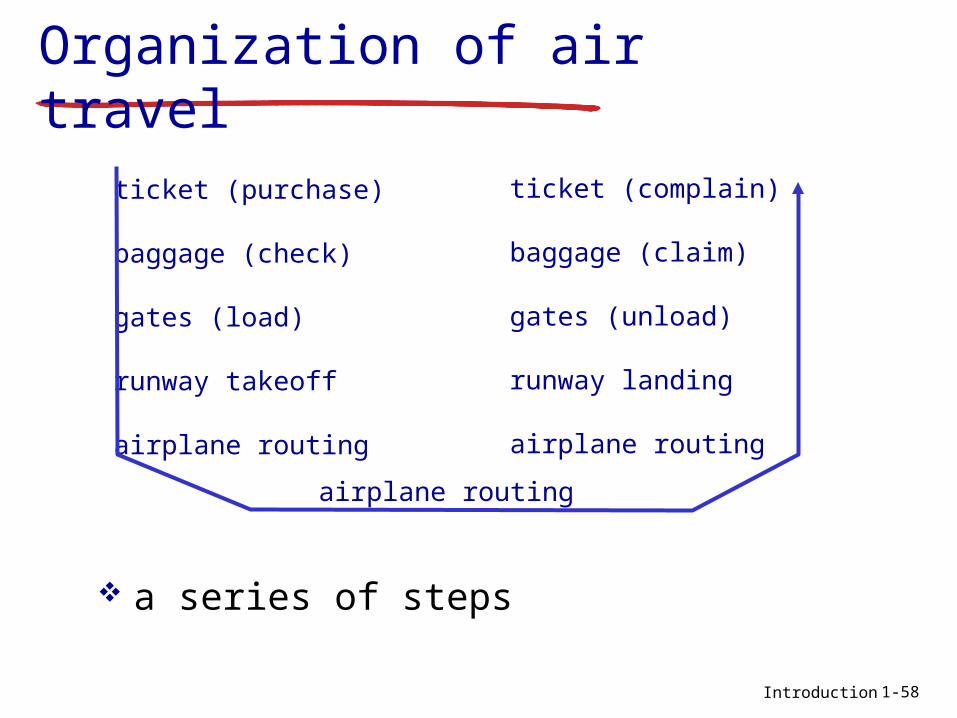
Organization of air travel
a series of steps
ticket (purchase)
baggage (check)
gates (load)
runway takeoff
airplane routing
ticket (complain)
baggage (claim)
gates (unload)
runway landing
airplane routing
airplane routing
1-58

Introduction
ticket (purchase)
baggage (check)
gates (load)
runway (takeoff)
airplane routing
departureairport
arrivalairport
intermediate air-trafficcontrol centers
airplane routing airplane routing
ticket (complain)
baggage (claim
gates (unload)
runway (land)
airplane routing
ticket
baggage
gate
takeoff/landing
airplane routing
Layering of airline functionality
layers: each layer implements a service via its own internal-layer actions relying on services provided by layer
below
1-59

Introduction
Why layering?dealing with complex systems: explicit structure allows identification,
relationship of complex system’s pieces layered reference model for discussion
modularization eases maintenance, updating of system change of implementation of layer’s service
transparent to rest of system e.g., change in gate procedure doesn’t
affect rest of system layering considered harmful?
1-60

Introduction
Internet protocol stack application: supporting
network applications FTP, SMTP, HTTP
transport: process-process data transfer TCP, UDP
network: routing of datagrams from source to destination IP, routing protocols
link: data transfer between neighboring network elements Ethernet, 802.111 (WiFi), PPP
physical: bits “on the wire”
application
transport
network
link
physical
1-61

Introduction
ISO/OSI reference model
presentation: allow applications to interpret meaning of data, e.g., encryption, compression, machine-specific conventions
session: synchronization, checkpointing, recovery of data exchange
Internet stack “missing” these layers! these services, if needed, must
be implemented in application needed?
application
presentation
session
transport
network
link
physical
1-62

Introduction
source
applicationtransportnetwork
linkphysical
HtHn M
segment Ht
datagram
destination
applicationtransportnetwork
linkphysical
HtHnHl M
HtHn M
Ht M
M
networklink
physical
linkphysical
HtHnHl M
HtHn M
HtHn M
HtHnHl M
router
switch
Encapsulationmessage M
Ht M
Hn
frame
1-63
M2-Internet Introduction 1-64
Sécurité
H. Fauconnier
M2-Internet Introduction 1-65
Network Security The field of network security is about:
how bad guys can attack computer networks how we can defend networks against attacks how to design architectures that are immune
to attacks Internet not originally designed with
(much) security in mind original vision: “a group of mutually trusting
users attached to a transparent network” Internet protocol designers playing “catch-
up” Security considerations in all layers!
H. Fauconnier

M2-Internet Introduction 1-66
Bad guys can put malware into hosts via Internet Malware can get in host from a virus, worm, or
trojan horse.
Spyware malware can record keystrokes, web sites visited, upload info to collection site.
Infected host can be enrolled in a botnet, used for spam and DDoS attacks.
Malware is often self-replicating: from an infected host, seeks entry into other hosts
H. Fauconnier

M2-Internet Introduction 1-67
Bad guys can put malware into hosts via Internet Trojan horse
Hidden part of some otherwise useful software
Today often on a Web page (Active-X, plugin)
Virus infection by receiving
object (e.g., e-mail attachment), actively executing
self-replicating: propagate itself to other hosts, users
Worm: infection by passively
receiving object that gets itself executed
self- replicating: propagates to other hosts, usersSapphire Worm: aggregate scans/sec
in first 5 minutes of outbreak (CAIDA, UWisc data)
H. Fauconnier

M2-Internet Introduction 1-68
Bad guys can attack servers and network infrastructure
Denial of service (DoS): attackers make resources (server, bandwidth) unavailable to legitimate traffic by overwhelming resource with bogus traffic
1. select target
2. break into hosts around the network (see botnet)
3. send packets toward target from compromised hosts
target
H. Fauconnier

M2-Internet Introduction 1-69
The bad guys can sniff packetsPacket sniffing:
broadcast media (shared Ethernet, wireless) promiscuous network interface reads/records all packets
(e.g., including passwords!) passing by
A
B
C
src:B dest:A payload
Wireshark software used for end-of-chapter labs is a (free) packet-sniffer
H. Fauconnier

M2-Internet Introduction 1-70
The bad guys can use false source addresses IP spoofing: send packet with false source
addressA
B
C
src:B dest:A payload
H. Fauconnier

M2-Internet Introduction 1-71
The bad guys can record and playback
record-and-playback: sniff sensitive info (e.g., password), and use later password holder is that user from system point of
view
A
B
C
src:B dest:A user: B; password: foo
H. Fauconnier

M2-Internet Introduction 1-72
Historique
H. Fauconnier

M2-Internet Introduction 1-73
Internet History
1961: Kleinrock - queueing theory shows effectiveness of packet-switching
1964: Baran - packet-switching in military nets
1967: ARPAnet conceived by Advanced Research Projects Agency
1969: first ARPAnet node operational
1972: ARPAnet public
demonstration NCP (Network Control
Protocol) first host-host protocol
first e-mail program ARPAnet has 15 nodes
1961-1972: Early packet-switching principles
H. Fauconnier
M2-Internet Introduction 1-74
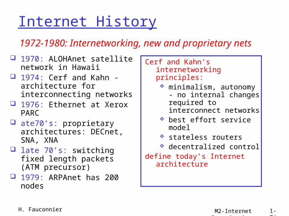
Internet History
1970: ALOHAnet satellite network in Hawaii
1974: Cerf and Kahn - architecture for interconnecting networks
1976: Ethernet at Xerox PARC
ate70’s: proprietary architectures: DECnet, SNA, XNA
late 70’s: switching fixed length packets (ATM precursor)
1979: ARPAnet has 200 nodes
Cerf and Kahn’s internetworking principles: minimalism, autonomy -
no internal changes required to interconnect networks
best effort service model stateless routers decentralized control
define today’s Internet architecture
1972-1980: Internetworking, new and proprietary nets
H. Fauconnier

M2-Internet Introduction 1-75
Internet History
1983: deployment of TCP/IP
1982: smtp e-mail protocol defined
1983: DNS defined for name-to-IP-address translation
1985: ftp protocol defined
1988: TCP congestion control
new national networks: Csnet, BITnet, NSFnet, Minitel
100,000 hosts connected to confederation of networks
1980-1990: new protocols, a proliferation of networks
H. Fauconnier

M2-Internet Introduction 1-76
Internet History
Early 1990’s: ARPAnet decommissioned
1991: NSF lifts restrictions on commercial use of NSFnet (decommissioned, 1995)
early 1990s: Web hypertext [Bush 1945,
Nelson 1960’s] HTML, HTTP: Berners-Lee 1994: Mosaic, later
Netscape late 1990’s:
commercialization of the Web
Late 1990’s – 2000’s: more killer apps: instant
messaging, P2P file sharing
network security to forefront
est. 50 million host, 100 million+ users
backbone links running at Gbps
1990, 2000’s: commercialization, the Web, new apps
H. Fauconnier

Introduction
2005-present ~750 million hosts
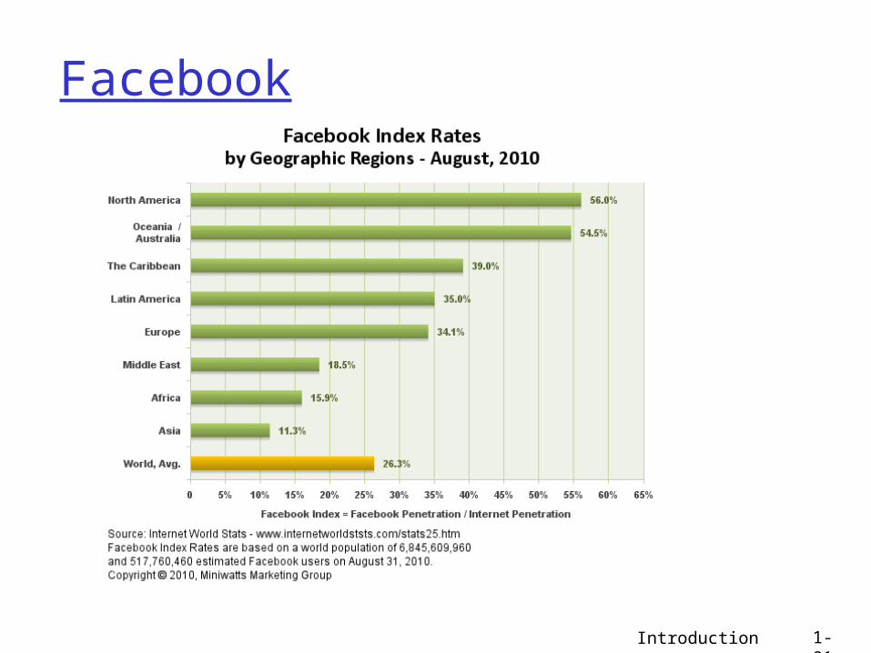
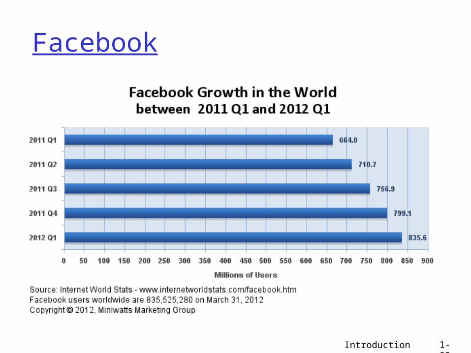
Smartphones and tablets Aggressive deployment of broadband access Increasing ubiquity of high-speed wireless access Emergence of online social networks:
Facebook: soon one billion users Service providers (Google, Microsoft) create their own
networks Bypass Internet, providing “instantaneous” access
to search, emai, etc. E-commerce, universities, enterprises running their
services in “cloud” (eg, Amazon EC2)
Internet history
1-77

Les standard internet
Internet Engineering Task Force (IETF) (ouvert) W3C (industriels fermé) RFC IETF:
Experimental Proposed standard Draft standard Standard Informational Historic
Niveau de recommandation Not recommended Limited use Elective Recommended required
H. Fauconnier M2-Internet Introduction 78

Internet 2011
Introduction 1-79

Internet 2011
Introduction 1-80
Introduction 1-81
Introduction 1-82

Introduction 1-83