
Installation Guide - TP-Link...2018/03/27 · About this Installation Guide This Installation Guide...
24
Business Networking Solution Installation Guide Jetstream Smart Switch T1500G-10MPS / T1600G-28TS / T1600G-28PS T1500-28TC (TL-SL2428) / T1500-28PCT (TL-SL2428P) T1600G-18TS (TL-SG2216) / T1600G-52TS (TL-SG2452) T1600G-52PS (TL-SG2452P) / T1700G-28TQ / T1700X-16TS
Transcript of Installation Guide - TP-Link...2018/03/27 · About this Installation Guide This Installation Guide...
Business Networking Solution
Installation GuideJetstream Smart Switch
T1500G-10MPS / T1600G-28TS / T1600G-28PS
T1500-28TC (TL-SL2428) / T1500-28PCT (TL-SL2428P)
T1600G-18TS (TL-SG2216) / T1600G-52TS (TL-SG2452)
T1600G-52PS (TL-SG2452P) / T1700G-28TQ / T1700X-16TS

About this Installation GuideThis Installation Guide describes the hardware characteristics, installation methods and the points that should be attended to during the installation. This Installation Guide is structured as follows:
Chapter 1 Introduction
This chapter describes the external components of the switch.
Chapter 2 Installation
This chapter illustrates how to install the switch.
Chapter 3 Connection
This chapter illustrates how to do the physical connection of the switch.
Appendix A Troubleshooting
Appendix B Hardware Specifications
AudienceThis Installation Guide is for:
Network Engineer Network Administrator
Conventions • Some models featured in this guide may be unavailable in your country or region. For local sales
information, visit http://www.tp-link.com.
• The figures in Chapter 2 to Chapter 3 are for demonstration purposes only. Your switch may differ in appearance from that depicted.
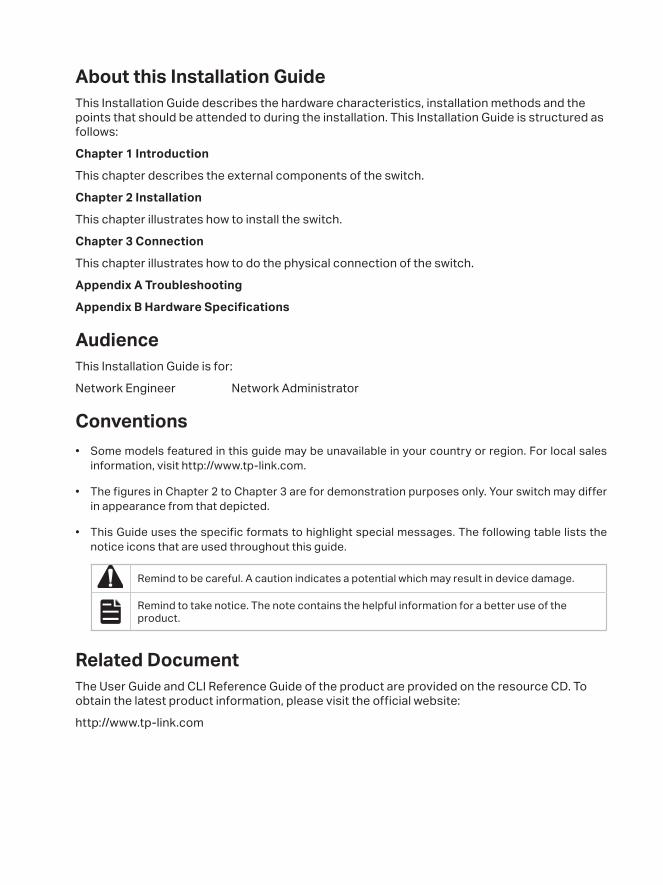
• This Guide uses the specific formats to highlight special messages. The following table lists the notice icons that are used throughout this guide.
Remind to be careful. A caution indicates a potential which may result in device damage.
Remind to take notice. The note contains the helpful information for a better use of the product.
Related DocumentThe User Guide and CLI Reference Guide of the product are provided on the resource CD. To obtain the latest product information, please visit the official website:
http://www.tp-link.com

Contents
Chapter 1 Introduction ——————————— 011.1 Product Overview ...........................................................011.2 Appearance .......................................................................01
Chapter 2 Installation ——————————— 082.1 Package Contents ..........................................................082.2 Safety Precautions .........................................................082.3 Installation Tools ..............................................................102.4 Product Installation ........................................................10
Chapter 3 Connection ——————————— 123.1 Ethernet Port ....................................................................123.2 SFP/SFP+ Port ..................................................................123.3 Verify Installation .............................................................133.4 Power On ............................................................................133.5 Initialization ........................................................................133.6 Accessing the Switch ....................................................13
Appendix A Troubleshooting ———————— 14
Appendix B Specifications ————————— 15
JetStream Smart Switch
01Introduction
Chapter 1 Introduction
1.1 Product Overview
Designed for workgroups and departments, TP-Link JetStream Smart Switch provides wire-speed performance and abundant L2 management features. It provides a variety of service features and multiple powerful functions with high security.
The EIA-standardized framework and smart configuration capacity can provide flexible solutions for a variable scale of networks. QoS and IGMP snooping/filtering optimize voice and video application. Link aggregation increases aggregated bandwidth, optimizing the transport of business critical data. SNMP, RMON, WEB and CLI Login bring abundant management policies. TP-LINK Gigabit Smart Switch integrates multiple functions with excellent performance, and is friendly to manage, which can fully meet the need of the users demanding higher networking performance.
T1500-28PCT/T1500G-10PS/T1500G-10MPS/T1600G-28PS (TL-SG2424P)/T1600G-52PS (TL-SG2452P) is also a Power Sourcing Equipment (PSE*). Some of the RJ45 ports on the switch support Power over Ethernet (PoE*) function, which can automatically detect and supply power with those powered devices (PDs*) complying with IEEE 802.3af and IEEE 802.3at.
*PSE: a device (switch or hub for instance) that provides power through an Ethernet cable.
*PoE: a technology describes a system to transmit electrical power, along with data, to remote devices over standard twisted-pair cable in an Ethernet.
*PD: a device powered by a PSE and thus consumes energy. Examples include powering network cameras, wireless LAN access points, IP telephones, network hubs, embedded computers etc.
1.2 Appearance
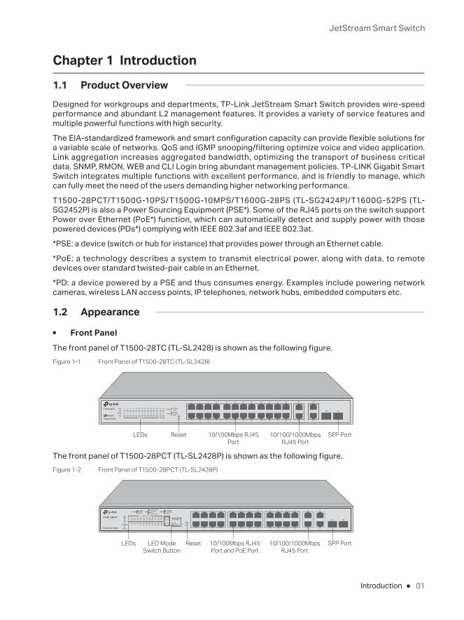
■ Front PanelThe front panel of T1500-28TC (TL-SL2428) is shown as the following figure.Figure 1-1 Front Panel of T1500-28TC (TL-SL2428)
LEDs Reset SFP Port10/100Mbps RJ45 Port
10/100/1000Mbps RJ45 Port
The front panel of T1500-28PCT (TL-SL2428P) is shown as the following figure.Figure 1-2 Front Panel of T1500-28PCT (TL-SL2428P)
LEDs Reset SFP Port10/100/1000Mbps RJ45 Port
10/100Mbps RJ45 Port and PoE Port
LED Mode Switch Button
JetStream Smart Switch
02 Introduction
The front panel of T1500G-10MPS is shown as the following figure.Figure 1-3 Front Panel of T1500G-10MPS
LEDs LED Mode Switch Button
Reset 10/100/1000Mbps RJ45 Port and PoE Port
SFP Port
The front panel of T1600G-18TS (TL-SG2216) is shown as the following figure.Figure 1-4 Front Panel of T1600G-18TS (TL-SG2216)
LEDs Reset 10/100/1000Mbps RJ45 Port SFP Port
The front panel of T1600G-28TS is shown as the following figure.Figure 1-5 Front Panel of T1600G-28TS
10/100/1000Mbps RJ45 PortLEDs Reset SFP Port
The front panel of T1600G-28PS is shown as the following figure.Figure 1-6 Front Panel of T1600G-28PS
LEDs Reset 10/100/1000Mbps RJ45 Port
SFP PortLED Mode Switch Button
The front panel of The T1600G-52TS (TL-SG2452) is shown as the following figure.Figure 1-7 Front Panel of T1600G-52TS (TL-SG2452)
Reset LEDs 10/100/1000Mbps RJ45 Port SFP Port
JetStream Smart Switch
03Introduction
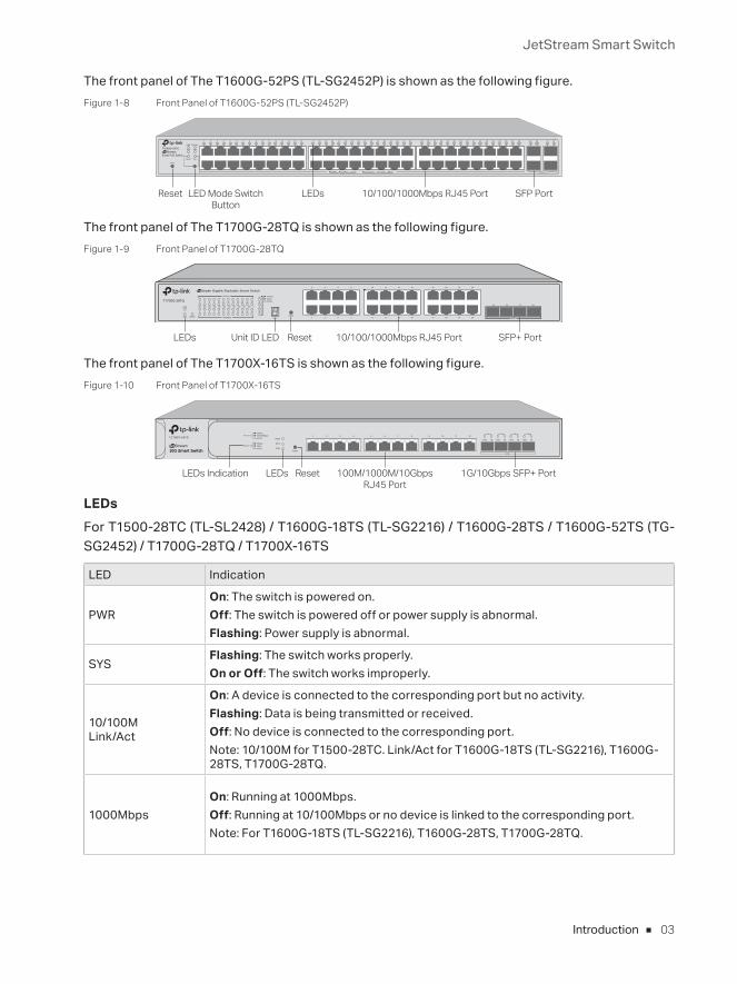
The front panel of The T1600G-52PS (TL-SG2452P) is shown as the following figure.Figure 1-8 Front Panel of T1600G-52PS (TL-SG2452P)
Reset LED Mode Switch Button
LEDs 10/100/1000Mbps RJ45 Port SFP Port
The front panel of The T1700G-28TQ is shown as the following figure.Figure 1-9 Front Panel of T1700G-28TQ
LEDs Unit ID LED Reset 10/100/1000Mbps RJ45 Port SFP+ Port
The front panel of The T1700X-16TS is shown as the following figure.Figure 1-10 Front Panel of T1700X-16TS
ResetLEDs 100M/1000M/10Gbps RJ45 Port
1G/10Gbps SFP+ PortLEDs Indication
LEDs For T1500-28TC (TL-SL2428) / T1600G-18TS (TL-SG2216) / T1600G-28TS / T1600G-52TS (TG-SG2452) / T1700G-28TQ / T1700X-16TS
LED Indication
PWR On: The switch is powered on.Off: The switch is powered off or power supply is abnormal.Flashing: Power supply is abnormal.
SYSFlashing: The switch works properly.On or Off: The switch works improperly.
10/100MLink/Act
On: A device is connected to the corresponding port but no activity.Flashing: Data is being transmitted or received.Off: No device is connected to the corresponding port.Note: 10/100M for T1500-28TC. Link/Act for T1600G-18TS (TL-SG2216), T1600G-28TS, T1700G-28TQ.
1000MbpsOn: Running at 1000Mbps.Off: Running at 10/100Mbps or no device is linked to the corresponding port.Note: For T1600G-18TS (TL-SG2216), T1600G-28TS, T1700G-28TQ.
JetStream Smart Switch
04 Introduction
LED Indication
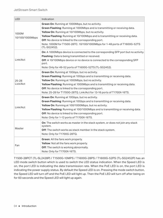
1000M10/100/1000Mbps
Green On: Running at 1000Mbps, but no activity.Green Flashing: Running at 1000Mbps and is transmitting or receiving data.Yellow On: Running at 10/100Mbps, but no activity.Yellow Flashing: Running at 10/100Mbps and is transmitting or receiving data.Off: No device is linked to the corresponding port.Note: 1000M for T1500-28TC. 10/100/1000Mbps for 1-48 ports of T1600G-52TS (TL-SG2452).
Link/Act
On: A 1000Mbps device is connected to the corresponding SFP port but no activity.Flashing: Data is being transmitted or received.Off: A 10/100Mbps device or no device is connected to the corresponding SFP port.Note: Only for 49-52 ports of T1600G-52TS (TL-SG2452).
25-28Lick/Act
Green On: Running at 10Gbps, but no activity.Green Flashing: Running at 10Gbps and is transmitting or receiving data.Yellow On: Running at 1000Mbps, but no activity.Yellow Flashing: Running at 1000Mbps and is transmitting or receiving data.Off: No device is linked to the corresponding port.Note: 25-28 for T1700G-28TQ. Link/Act for 13-16 ports of T1700X-16TS.
Link/Act
Green On: Running at 10Gbps, but no activity.Green Flashing: Running at 10Gbps and is transmitting or receiving data.Yellow On: Running at 100/1000Mbps, but no activity.Yellow Flashing: Running at 100/1000Mbps and is transmitting or receiving data.Off: No device is linked to the corresponding port.Note: Only for 1-12 ports of T1700X-16TS.
Master
On: The switch works as master in the stack system, or does not join any stack system.Off: The switch works as stack member in the stack system.Note: Only for T1700G-28TQ.
Fan
Green: All the fans work properly.Yellow: Not all the fans work properly.Off: The switch is working abnormally.Note: Only for T1700X-16TS.
T1500-28PCT (TL-SL2428P) / T1500G-10MPS / T1600G-28PS / T1600G-52PS (TL-SG2452P) has an LED mode switch button which is used to switch the LED status indication. When the Speed LED is on, the port LED is indicating the data transmission rate. When the PoE LED is on, the port LED is indicating the power supply status. By default the Speed LED is on. Pressing the mode switch button, the Speed LED will turn off and the PoE LED will light up. Then the PoE LED will turn off after being on for 60 seconds and the Speed LED will light up again.
JetStream Smart Switch
05Introduction
LED Indication
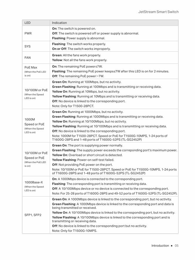
PWROn: The switch is powered on.Off: The switch is powered off or power supply is abnormal.Flashing: Power supply is abnormal.
SYSFlashing: The switch works properly.On or Off: The switch works improperly.
FAN Green: All the fans work properly.Yellow: Not all the fans work properly.
PoE Max(When the PoE LED is on)
On: The remaining PoE power≤7W.Flashing: The remaining PoE power keeps≤7W after this LED is on for 2 minutes.Off: The remaining PoE power>7W.
10/100M or PoE (When the Speed LED is on)
Green On: Running at 100Mbps, but no activity.Green Flashing: Running at 100Mbps and is transmitting or receiving data.Yellow On: Running at 10Mbps, but no activity.Yellow Flashing: Running at 10Mbps and is transmitting or receiving data.Off: No device is linked to the corresponding port.Note: Only for T1500-28PCT.
1000MSpeed or PoE (When the Speed LED is on)
Green On: Running at 1000Mbps, but no activity.Green Flashing: Running at 1000Mbps and is transmitting or receiving data.Yellow On: Running at 10/100Mbps, but no activity.Yellow Flashing: Running at 10/100Mbps and is transmitting or receiving data.Off: No device is linked to the corresponding port.Note: 1000M for T1500-28PCT. Speed or PoE for T1500G-10MPS, 1-24 ports of T1600G-28PS and 1-48 ports of T1600G-52PS (TL-SG2452P)
10/100M or PoESpeed or PoE (When the PoE LED is on)
Green On: The port is supplying power normally.Green Flashing: The supply power exceeds the correponding port's maximum power.Yellow On: Overload or short circuit is detected.Yellow Flashing: Power-on self-test failed.Off: Not providing PoE power on the port.Note: 10/100M or PoE for T1500-28PCT. Speed or PoE for T1500G-10MPS, 1-24 ports of T1600G-28PS and 1-48 ports of T1600G-52PS (TL-SG2452P)
1000Base-X(When the Speed LED is on)
On: A 1000Mbps device is connected to the corresponding port.Flashing: The corresponding port is transmitting or receiving data.Off: A 10/100Mbps device or no device is connected to the corresponding port.Note: For 25-28 ports of T1600G-28PS and 49-52 ports of T1600G-52PS (TL-SG2452P).
SFP1, SFP2
Green On: A 1000Mbps device is linked to the corresponding port, but no activity.Green Flashing: A 1000Mbps device is linked to the corresponding port and data is being transmitted or received.Yellow On: A 10/100Mbps device is linked to the corresponding port, but no activity.Yellow Flashing: A 10/100Mbps device is linked to the corresponding port and is transmitting or receiving data.Off: No device is linked to the corresponding port but no activity.Note: Only for T1500G-10MPS.
JetStream Smart Switch
06 Introduction
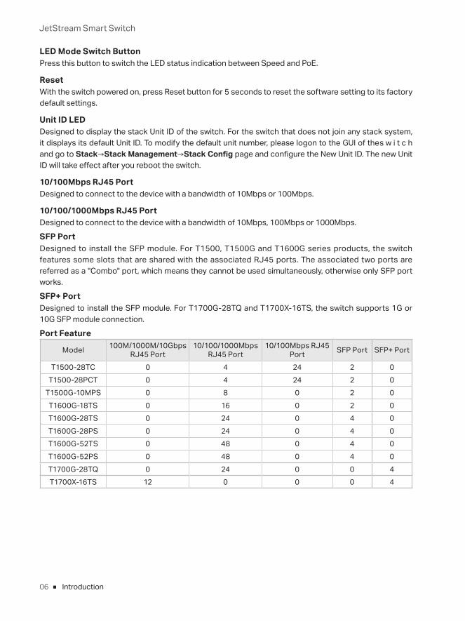
LED Mode Switch ButtonPress this button to switch the LED status indication between Speed and PoE.
ResetWith the switch powered on, press Reset button for 5 seconds to reset the software setting to its factory default settings.
Unit ID LEDDesigned to display the stack Unit ID of the switch. For the switch that does not join any stack system, it displays its default Unit ID. To modify the default unit number, please logon to the GUI of the s w i t c h and go to Stack→Stack Management→Stack Config page and configure the New Unit ID. The new Unit ID will take effect after you reboot the switch.
10/100Mbps RJ45 PortDesigned to connect to the device with a bandwidth of 10Mbps or 100Mbps.
10/100/1000Mbps RJ45 PortDesigned to connect to the device with a bandwidth of 10Mbps, 100Mbps or 1000Mbps.
SFP PortDesigned to install the SFP module. For T1500, T1500G and T1600G series products, the switch features some slots that are shared with the associated RJ45 ports. The associated two ports are referred as a "Combo" port, which means they cannot be used simultaneously, otherwise only SFP port works.
SFP+ PortDesigned to install the SFP module. For T1700G-28TQ and T1700X-16TS, the switch supports 1G or 10G SFP module connection.
Port Feature
Model 100M/1000M/10Gbps RJ45 Port
10/100/1000Mbps RJ45 Port
10/100Mbps RJ45 Port SFP Port SFP+ Port
T1500-28TC 0 4 24 2 0T1500-28PCT 0 4 24 2 0
T1500G-10MPS 0 8 0 2 0T1600G-18TS 0 16 0 2 0T1600G-28TS 0 24 0 4 0T1600G-28PS 0 24 0 4 0T1600G-52TS 0 48 0 4 0T1600G-52PS 0 48 0 4 0T1700G-28TQ 0 24 0 0 4T1700X-16TS 12 0 0 0 4
JetStream Smart Switch
07Introduction
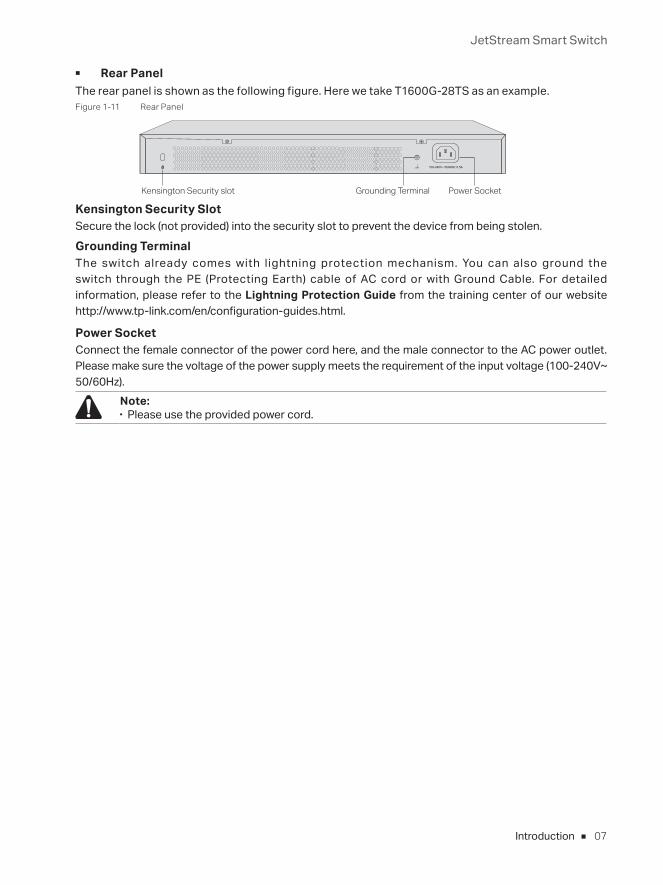
■ Rear PanelThe rear panel is shown as the following figure. Here we take T1600G-28TS as an example.Figure 1-11 Rear Panel
Power SocketGrounding TerminalKensington Security slot
Kensington Security SlotSecure the lock (not provided) into the security slot to prevent the device from being stolen.
Grounding TerminalThe switch already comes with lightning protection mechanism. You can also ground the switch through the PE (Protecting Earth) cable of AC cord or with Ground Cable. For detailed information, please refer to the Lightning Protection Guide from the training center of our website http://www.tp-link.com/en/configuration-guides.html.
Power SocketConnect the female connector of the power cord here, and the male connector to the AC power outlet. Please make sure the voltage of the power supply meets the requirement of the input voltage (100-240V~ 50/60Hz).
Note: ■ Please use the provided power cord.
JetStream Smart Switch
08 Installation
Chapter 2 Installation
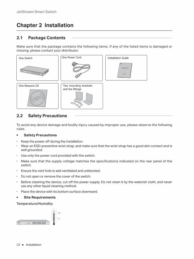
2.1 Package Contents
Make sure that the package contains the following items. If any of the listed items is damaged or missing, please contact your distributor.
One Switch Installation Guide
Installation Guide
Business Networking Solution
Two mounting brackets and the fittings
One Resouce CD
One Power Cord
2.2 Safety Precautions
To avoid any device damage and bodily injury caused by improper use, please observe the following rules.
■ Safety Precautions ■ Keep the power off during the installation. ■ Wear an ESD-preventive wrist strap, and make sure that the wrist strap has a good skin contact and is
well grounded. ■ Use only the power cord provided with the switch. ■ Make sure that the supply voltage matches the specifications indicated on the rear panel of the
switch. ■ Ensure the vent hole is well ventilated and unblocked. ■ Do not open or remove the cover of the switch. ■ Before cleaning the device, cut off the power supply. Do not clean it by the waterish cloth, and never
use any other liquid cleaning method. ■ Place the device with its bottom surface downward. ■ Site Requirements
Temperature/Humidity
40℃
0℃
JetStream Smart Switch
09Installation
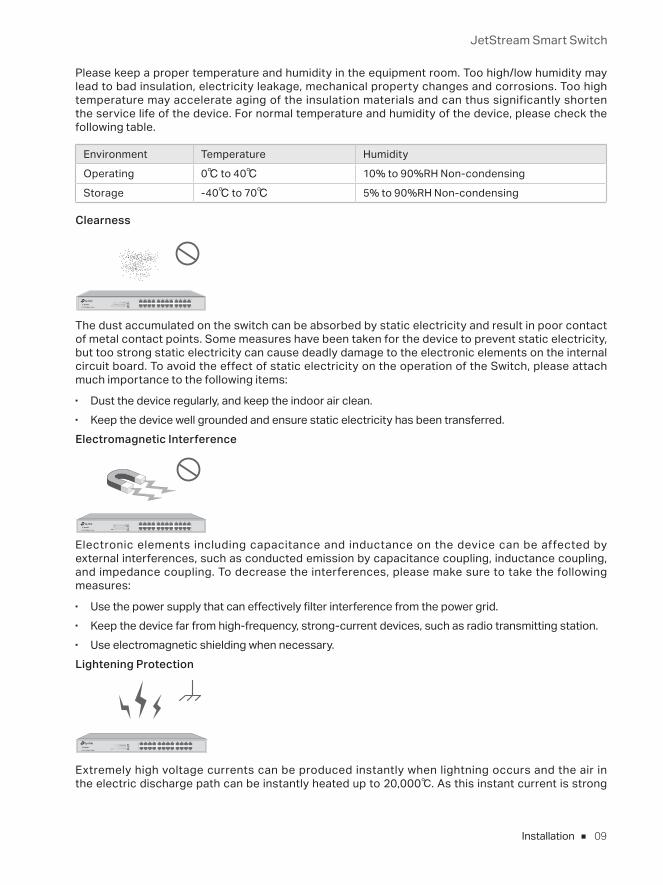
Please keep a proper temperature and humidity in the equipment room. Too high/low humidity may lead to bad insulation, electricity leakage, mechanical property changes and corrosions. Too high temperature may accelerate aging of the insulation materials and can thus significantly shorten the service life of the device. For normal temperature and humidity of the device, please check the following table.
Environment Temperature Humidity
Operating 0℃ to 40℃ 10% to 90%RH Non-condensing
Storage -40℃ to 70℃ 5% to 90%RH Non-condensing
Clearness
The dust accumulated on the switch can be absorbed by static electricity and result in poor contact of metal contact points. Some measures have been taken for the device to prevent static electricity, but too strong static electricity can cause deadly damage to the electronic elements on the internal circuit board. To avoid the effect of static electricity on the operation of the Switch, please attach much importance to the following items:
■ Dust the device regularly, and keep the indoor air clean. ■ Keep the device well grounded and ensure static electricity has been transferred.Electromagnetic Interference
Electronic elements including capacitance and inductance on the device can be affected by external interferences, such as conducted emission by capacitance coupling, inductance coupling, and impedance coupling. To decrease the interferences, please make sure to take the following measures:
■ Use the power supply that can effectively filter interference from the power grid. ■ Keep the device far from high-frequency, strong-current devices, such as radio transmitting station. ■ Use electromagnetic shielding when necessary.Lightening Protection
Extremely high voltage currents can be produced instantly when lightning occurs and the air in the electric discharge path can be instantly heated up to 20,000℃. As this instant current is strong
JetStream Smart Switch
10 Installation
enough to damage electronic devices, more effective lightning protection measures should be taken.
■ Ensure the rack and device are well earthed. ■ Make sure the power socket has a good contact with the ground. ■ Keep a reasonable cabling system and avoid induced lightning. ■ Use the signal SPD (Surge Protective Device) when wiring outdoor.
Note: For detailed lightning protection measures, please refer to the Lightning Protection Guide from the training center of our website http://www.tp-link.com/en/configuration-guides.html.
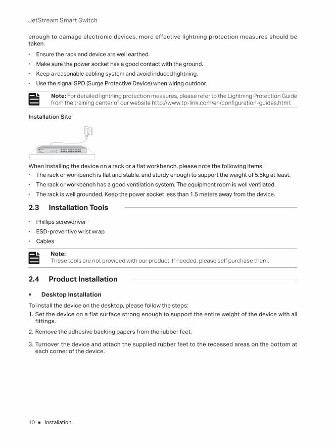
Installation Site
When installing the device on a rack or a flat workbench, please note the following items: ■ The rack or workbench is flat and stable, and sturdy enough to support the weight of 5.5kg at least. ■ The rack or workbench has a good ventilation system. The equipment room is well ventilated. ■ The rack is well grounded. Keep the power socket less than 1.5 meters away from the device.
2.3 Installation Tools ■ Phillips screwdriver ■ ESD-preventive wrist wrap ■ Cables
Note: These tools are not provided with our product. If needed, please self purchase them.
2.4 Product Installation
■ Desktop InstallationTo install the device on the desktop, please follow the steps:1. Set the device on a flat surface strong enough to support the entire weight of the device with all
fittings.
2. Remove the adhesive backing papers from the rubber feet.
3. Turnover the device and attach the supplied rubber feet to the recessed areas on the bottom at each corner of the device.
JetStream Smart Switch
11Installation
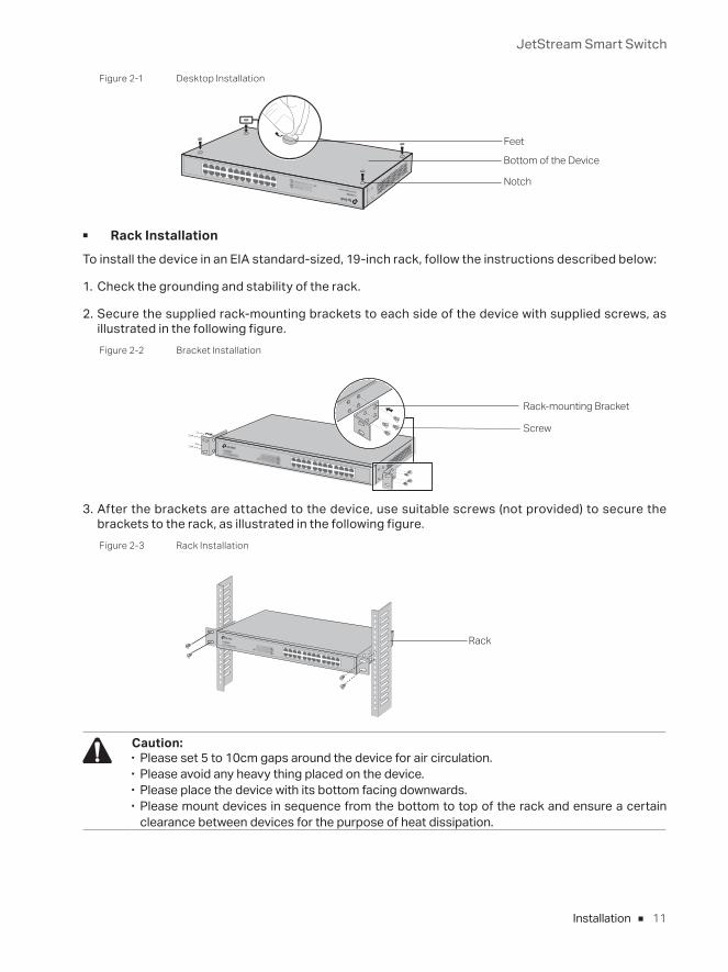
Figure 2-1 Desktop Installation
Feet
Bottom of the Device
Notch
■ Rack InstallationTo install the device in an EIA standard-sized, 19-inch rack, follow the instructions described below:
1. Check the grounding and stability of the rack.
2. Secure the supplied rack-mounting brackets to each side of the device with supplied screws, as illustrated in the following figure.Figure 2-2 Bracket Installation
Rack-mounting Bracket
Screw
3. After the brackets are attached to the device, use suitable screws (not provided) to secure the brackets to the rack, as illustrated in the following figure.Figure 2-3 Rack Installation
Rack
Caution: ■ Please set 5 to 10cm gaps around the device for air circulation. ■ Please avoid any heavy thing placed on the device. ■ Please place the device with its bottom facing downwards. ■ Please mount devices in sequence from the bottom to top of the rack and ensure a certain
clearance between devices for the purpose of heat dissipation.
JetStream Smart Switch
12 Connection
Chapter 3 Connection
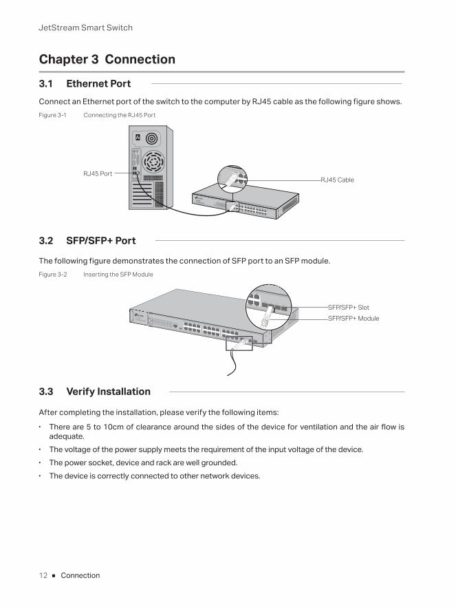
3.1 Ethernet PortConnect an Ethernet port of the switch to the computer by RJ45 cable as the following figure shows.Figure 3-1 Connecting the RJ45 Port
RJ45 PortRJ45 Cable
3.2 SFP/SFP+ Port
The following figure demonstrates the connection of SFP port to an SFP module.Figure 3-2 Inserting the SFP Module
SFP/SFP+ SlotSFP/SFP+ Module
3.3 Verify Installation
After completing the installation, please verify the following items: ■ There are 5 to 10cm of clearance around the sides of the device for ventilation and the air flow is
adequate. ■ The voltage of the power supply meets the requirement of the input voltage of the device. ■ The power socket, device and rack are well grounded. ■ The device is correctly connected to other network devices.
JetStream Smart Switch
13Connection
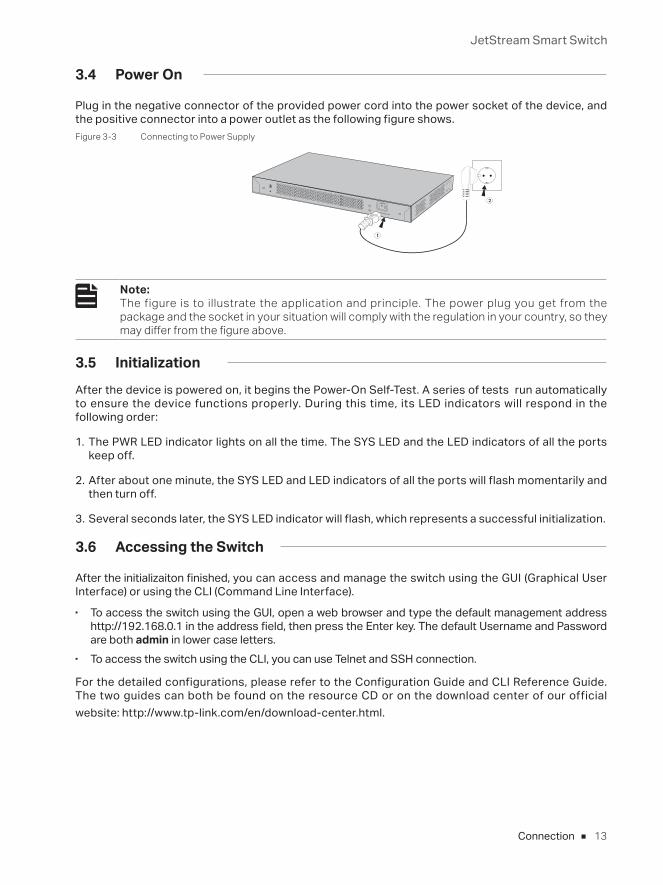
3.4 Power On
Plug in the negative connector of the provided power cord into the power socket of the device, and the positive connector into a power outlet as the following figure shows.Figure 3-3 Connecting to Power Supply
100-240V~50/60Hz 0.5A
Note: The figure is to illustrate the application and principle. The power plug you get from the package and the socket in your situation will comply with the regulation in your country, so they may differ from the figure above.
3.5 Initialization
After the device is powered on, it begins the Power-On Self-Test. A series of tests run automatically to ensure the device functions properly. During this time, its LED indicators will respond in the following order:
1. The PWR LED indicator lights on all the time. The SYS LED and the LED indicators of all the ports keep off.
2. After about one minute, the SYS LED and LED indicators of all the ports will flash momentarily and then turn off.
3. Several seconds later, the SYS LED indicator will flash, which represents a successful initialization.
3.6 Accessing the Switch
After the initializaiton finished, you can access and manage the switch using the GUI (Graphical User Interface) or using the CLI (Command Line Interface).
■ To access the switch using the GUI, open a web browser and type the default management address http://192.168.0.1 in the address field, then press the Enter key. The default Username and Password are both admin in lower case letters.
■ To access the switch using the CLI, you can use Telnet and SSH connection.
For the detailed configurations, please refer to the Configuration Guide and CLI Reference Guide. The two guides can both be found on the resource CD or on the download center of our official website: http://www.tp-link.com/en/download-center.html.
JetStream Smart Switch
14 Appendix A Troubleshooting
Appendix A TroubleshootingQ1. What could I do if I forgot the username and password of the switch?
Press the Reset button for at least 5 seconds to reset the system. The system will be reset to the factory default settings, and the default login user name and password are both admin.
Q2. Why does the PWR/Power LED work abnormally?
The PWR/Power LED should be lit up when the power system works normally. If the PWR LED worked abnormally, please take the following steps:1. Make sure that the power cable is connected properly, and the power contact is normal.2. Make sure the voltage of the power supply meets the requirement of the input voltage of the
switch.
Q3. What should I do if I cannot access the web management page?
Please try the following:
1. Check every port LED on the switch and make sure the Ethernet cable is connected properly.2. Try another port on the switch and make sure the Ethernet cable is suitable and works normally.3. Power off the switch and, after a while, power it on again.4. Make sure the IP address of your PC is set within the subnet of the switch.5. If you still cannot access the configuration page, please restore the switch to its factory defaults.
Then the IP address of your PC should be set as 192.168.0.x ("x" is any number from 2 to 254) and Subnet Mask as 255.255.255.0.
JetStream Smart Switch
15Appendix B Specifications
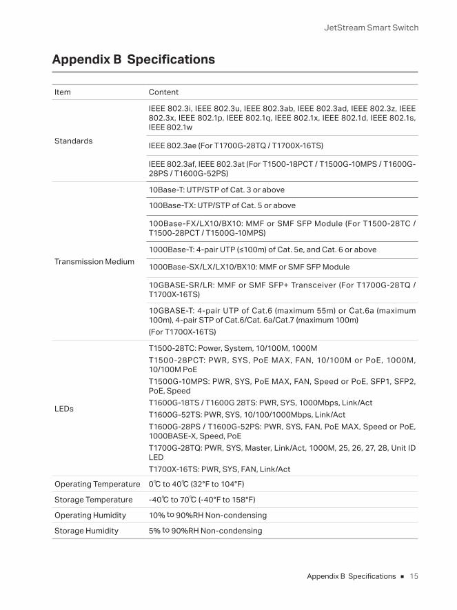
Appendix B Specifications
Item Content
Standards
IEEE 802.3i, IEEE 802.3u, IEEE 802.3ab, IEEE 802.3ad, IEEE 802.3z, IEEE 802.3x, IEEE 802.1p, IEEE 802.1q, IEEE 802.1x, IEEE 802.1d, IEEE 802.1s, IEEE 802.1w
IEEE 802.3ae (For T1700G-28TQ / T1700X-16TS)
IEEE 802.3af, IEEE 802.3at (For T1500-18PCT / T1500G-10MPS / T1600G-28PS / T1600G-52PS)
Transmission Medium
10Base-T: UTP/STP of Cat. 3 or above
100Base-TX: UTP/STP of Cat. 5 or above
100Base-FX/LX10/BX10: MMF or SMF SFP Module (For T1500-28TC / T1500-28PCT / T1500G-10MPS)
1000Base-T: 4-pair UTP (≤100m) of Cat. 5e, and Cat. 6 or above
1000Base-SX/LX/LX10/BX10: MMF or SMF SFP Module
10GBASE-SR/LR: MMF or SMF SFP+ Transceiver (For T1700G-28TQ / T1700X-16TS)
10GBASE-T: 4-pair UTP of Cat.6 (maximum 55m) or Cat.6a (maximum 100m), 4-pair STP of Cat.6/Cat. 6a/Cat.7 (maximum 100m)(For T1700X-16TS)
LEDs
T1500-28TC: Power, System, 10/100M, 1000MT1500-28PCT: PWR, SYS, PoE MAX, FAN, 10/100M or PoE, 1000M, 10/100M PoET1500G-10MPS: PWR, SYS, PoE MAX, FAN, Speed or PoE, SFP1, SFP2, PoE, SpeedT1600G-18TS / T1600G 28TS: PWR, SYS, 1000Mbps, Link/ActT1600G-52TS: PWR, SYS, 10/100/1000Mbps, Link/ActT1600G-28PS / T1600G-52PS: PWR, SYS, FAN, PoE MAX, Speed or PoE, 1000BASE-X, Speed, PoET1700G-28TQ: PWR, SYS, Master, Link/Act, 1000M, 25, 26, 27, 28, Unit ID LEDT1700X-16TS: PWR, SYS, FAN, Link/Act
Operating Temperature 0℃ to 40℃ (32°F to 104°F)
Storage Temperature -40℃ to 70℃ (-40°F to 158°F)
Operating Humidity 10% to 90%RH Non-condensing
Storage Humidity 5% to 90%RH Non-condensing

FCC STATEMENTThis equipment has been tested and found to comply with the limits for a Class A digital device, pursuant to part 15 of the FCC Rules. These limits are designed to provide reasonable protection against harmful interference when the equipment is operated in a commercial environment. This equipment generates, uses, and can radiate radio frequency energy and, if not installed and used in accordance with the instruction manual, may cause harmful interference to radio communications. Operation of this equipment in a residential area is likely to cause harmful interference in which case the user will be required to correct the interference at his own expense.This device complies with part 15 of the FCC Rules. Operation is subject to the following two conditions:1) This device may not cause harmful interference.2) This device must accept any interference received, including interference that may cause undesired operation.Any changes or modifications not expressly approved by the party responsible for compliance could void the user’s authority to operate the equipment.
CE Mark Warning
This is a class A product. In a domestic environment, this product may cause radio interference, in which case the user may be required to take adequate measures.
EU declaration of conformityTP-Link hereby declares that the device is in compliance with the essential requirements and other relevant provisions of directives 2014/30/EU, 2014/35/EU, 2009/125/EC and 2011/65/EU.
The original EU declaration of conformity may be found at http://www.tp-link.com/en/ce
Продукт сертифіковано згідно с правилами системи УкрСЕПРО на відповідність вимогам нормативних документів та вимогам, що передбачені чинними законодавчими актами України.
Safety Information• When product has power button, the power button is one of the way to shut off the product;
when there is no power button, the only way to completely shut off power is to disconnect the product or the power adapter from the power source.
• Don’t disassemble the product, or make repairs yourself. You run the risk of electric shock and voiding the limited warranty. If you need service, please contact us.
• Avoid water and wet locations.

BSMI Notice安全諮詢及注意事項 • 請使用原裝電源供應器或只能按照本產品注明的電源類型使用本產品。
• 清潔本產品之前請先拔掉電源線。請勿使用液體、噴霧清潔劑或濕布進行清潔。
• 注意防潮,請勿將水或其他液體潑灑到本產品上。
• 插槽與開口供通風使用,以確保本產品的操作可靠並防止過熱,請勿堵塞或覆蓋開口。
• 請勿將本產品置放於靠近熱源的地方。除非有正常的通風,否則不可放在密閉位置中。
• 請不要私自打開機殼,不要嘗試自行維修本產品,請由授權的專業人士進行此項工作。
• 此為甲類資訊技術設備,于居住環境中使用時,可能會造成射頻擾動,在此種情況下,使用者會被要求採取
某些適當的對策。
限用物質含有情況標示聲明書
產品元件名稱
限用物質及其化學符號
鉛
Pb鎘
Cd汞 Hg
六價鉻 CrVI
多溴聯苯
PBB多溴二苯醚
PBDEPCB ○ ○ ○ ○ ○ ○
外殼 ○ ○ ○ ○ ○ ○
備考1. "超出0.1 wt %" 及 "超出0.01 wt %" 系指限用物質之百分比含量超出百分比含量基準值。
備考2. "○"系指該項限用物質之百分比含量未超出百分比含量基準值。
備考3. " - " 系指該項限用物質為排除項目。
Industry Canada StatementCAN ICES-3 (A)/NMB-3(A)
Explanation of the symbols on the product labelSymbol Explanation
AC voltage
Indoor use only
RECYCLING
This product bears the selective sorting symbol for Waste electrical and electronic equipment (WEEE). This means that this product must be handled pursuant to European directive 2012/19/EU in order to be recycled or dismantled to minimize its impact on the environment.
User has the choice to give his product to a competent recycling organization or to the retailer when he buys a new electrical or electronic equipment.

この装置は、クラスA情報技術装置です。この装置を家庭環境で使用すると電波妨害を引き起こすことがあります。この場合には使用者が適切な対策を講ずるよう要求されることがあります。 VCCI-A


© 2017 TP-Link 7106507852 REV3.0.0
For technical support, User Guide and other information, please visit http://www.tp-link.com/support, or simply scan the QR code


![Table of Contents - Pennant International Group plc1].pdfPENNANT SOFTWARE SOLUTIONS OmegaPS S ΠR14.2.00 Update Installation Guide This software/documentation contains proprietary](https://static.fdocuments.fr/doc/165x107/60bd801411af5942197bdcba/table-of-contents-pennant-international-group-plc-1pdf-pennant-software-solutions.jpg)