Infrared Thermography as an Inspection and Maintenance … · - safety: asset protection and...
11
2017 Infrared Thermography as an Inspection and Maintenance Technique in Industry Attílio Bruno Veratti ICON Tecnologia Sao Paulo, Brazil [email protected] Erandy Flores Guevara SERCA Veracruz, Mexico +521 9211549178, [email protected] Abstrac From its beginning, during the mid-60’s, thermography inspection has been characterized mainly as a great ally within condition-based maintenance. This paper aims to highlight its advantages, which, from personal experience, are always important to remind to our clients. In addition, it presents two case studies which evidence its importance related to a production process continuity, as well as the facility and workers safety; without, however, leaving behind the need of having both a qualified thermographer and an adecuate procedure. Introduction Infrared thermography is a remote monitoring technique which allows the measurement of temperatures and the formation of thermal images of a component, equipment or process, from the natural infrared radiation they emit. Its diverse characteristics such as not being intrusive, having a working distance allowance, capturing and conserving thermal information (radiometric image) via an infrared image, allowing its analysis in real time or in the future, among others, have enabled thermography to be used in different application fields; for example: - maintenance: equipment inspection and condition monitoring - production processes: automatization and thermal variables control - medicine: testing techniques and metabolic monitoring - research: thermal studies of (destructive / non-destructive) testing and processes - safety: asset protection and intrusion detection - army: object detection, night vision and scope systems However, it is undeniable that, 52 years after this technology was released for civil use, since the mid-60s up to date, most thermographic systems marketed around the world, as well as the personnel involved with the use of thermography, are mainly involved with maintenance. Even though the importance of maintenance within the industry seems evident, in a world which demands non-stop products and services, in addition to the economic gain (for producers, businessmen, investors and employers) that comes with them, we consider that it
Transcript of Infrared Thermography as an Inspection and Maintenance … · - safety: asset protection and...
2017
Infrared Thermography as an Inspection and Maintenance Technique in Industry
Attílio Bruno Veratti ICON Tecnologia Sao Paulo, Brazil
Erandy Flores Guevara SERCA
Veracruz, Mexico +521 9211549178, [email protected]
Abstrac
From its beginning, during the mid-60’s, thermography inspection has been characterized mainly as a great ally within condition-based maintenance. This paper aims to highlight its advantages, which, from personal experience, are always important to remind to our clients. In addition, it presents two case studies which evidence its importance related to a production process continuity, as well as the facility and workers safety; without, however, leaving behind the need of having both a qualified thermographer and an adecuate procedure.
Introduction
Infrared thermography is a remote monitoring technique which allows the measurement of temperatures and the formation of thermal images of a component, equipment or process, from the natural infrared radiation they emit. Its diverse characteristics such as not being intrusive, having a working distance allowance, capturing and conserving thermal information (radiometric image) via an infrared image, allowing its analysis in real time or in the future, among others, have enabled thermography to be used in different application fields; for example:
- maintenance: equipment inspection and condition monitoring - production processes: automatization and thermal variables control - medicine: testing techniques and metabolic monitoring - research: thermal studies of (destructive / non-destructive) testing and processes - safety: asset protection and intrusion detection - army: object detection, night vision and scope systems
However, it is undeniable that, 52 years after this technology was released for civil use, since the mid-60s up to date, most thermographic systems marketed around the world, as well as the personnel involved with the use of thermography, are mainly involved with maintenance. Even though the importance of maintenance within the industry seems evident, in a world which demands non-stop products and services, in addition to the economic gain (for producers, businessmen, investors and employers) that comes with them, we consider that it
2017
never hurts to make emphasis on it. Also, the concepts relating to this activity should be reviewed.
Why does Maintenance exist?
All equipment is subject to deterioration processes, as a result of the natural wear and tear mechanisms and their use. Maintenance is an activity which aims to, affordably, detect these wears and tear mechanisms and identify failure modes that may be present in the equipment, with the purpose of achieving top performance within the production system. Perhaps it is not surprising that certain technology originally conceived for military applications works very well with maintenance since the objectives of both disciplines share some similarities.
Military Strategy Maxims within the Context of Maintenance
“If you know the enemy and know yourself, you need not fear the result of a hundred battles.” In other words, we should know, identify and locate, in advanced, failure mechanisms present in our equipment. Otherwise, the enemy (failures) will be the one to find and attack us in the most catastrophic and possible way! [If war is inevitable, we must] “fight at the moment, in the field and under the chosen circumstances for us.” In other words, we must have the capacity of deciding when and under what circumstances we should act. We must be able to plan efficiently. Otherwise, the failure will be the one to decide when and how this will happen! And it is very likely to happen in the worst moment: Sunday at 4:00 a.m., when production is at its peak, when the replacement is not available, when competent personnel who are able to do reparations are missing, when the failure puts the employees’ safety and/or the prestige of the company at risk, among others. It is important to remember that failures are not events but processes. Their previous identification relies on the appropriate inspection techniques. Mainly speaking, people in charge of maintenance are responsible for the conditions in which they will be working with. From the very first moment of designing a project, choosing equipment with suitable maintainability and “inspectionallty” simplify our task. Maintainability:
- The quality of a component, product, equipment or system when receiving maintenance within a specific period of time and at a prearranged cost.
- Probability of a system, after having failed, of returning to original operational conditions, under certain circumstances, within a certain period of time.
Inspectionabilty:
- The quality of a component, product, equipment or system of being safely inspected, within a specific period of time and at a prearranged cost.
2017
Thermographic Inspection
Inspection Techniques are extensions of our senses which aim to make the operational state of a component noticeable and reveal the wear and tear signs, at their initial stages. Ergo, thermographic inspection is the one which is carried out by means of an infrared thermographic measurement procedure, with the aim of providing information relating to the operational condition of a component. Responsible decision-making based on the best available information is part of maintenance management. For a company, it is vital to have an infrared thermographic inspection procedure involving training, criteria and safety requirements. It must be noticed than, the role and responsibilities involved with all aspects of the infrared thermographic inspection procedure, is carried out by a thermographer with a level (category) 3 certification. As it is well known, when considering electrical systems, thermography is one of the main information resources. For this reason, in order to translate the above-mentioned terminology into real field practice, two case studies dealing with thermographic inspections in electrical systems are presented. Two particular cases regarding electrical oil filled transformers are discussed: one with an anomaly revealed due to a high temperature increment and another; a more subtle-to-detect
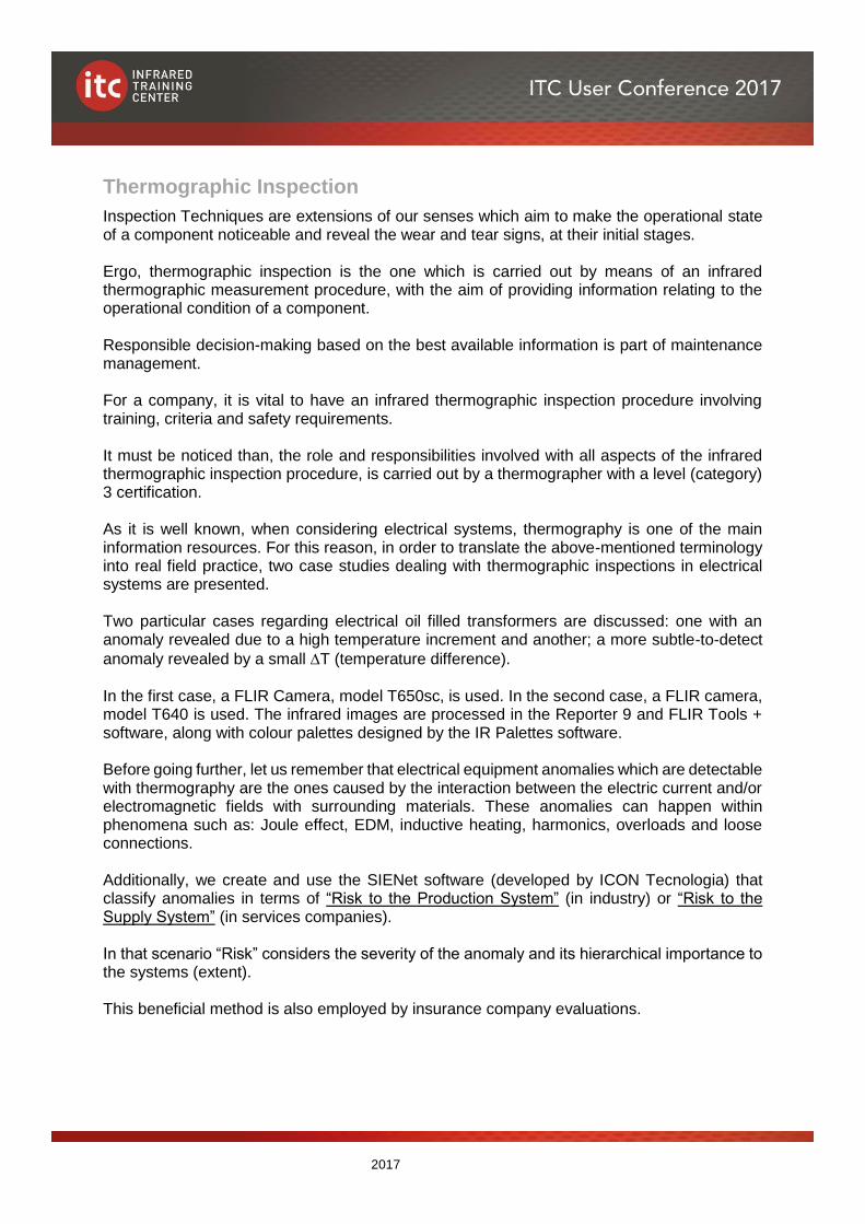
anomaly revealed by a small T (temperature difference). In the first case, a FLIR Camera, model T650sc, is used. In the second case, a FLIR camera, model T640 is used. The infrared images are processed in the Reporter 9 and FLIR Tools + software, along with colour palettes designed by the IR Palettes software. Before going further, let us remember that electrical equipment anomalies which are detectable with thermography are the ones caused by the interaction between the electric current and/or electromagnetic fields with surrounding materials. These anomalies can happen within phenomena such as: Joule effect, EDM, inductive heating, harmonics, overloads and loose connections. Additionally, we create and use the SIENet software (developed by ICON Tecnologia) that classify anomalies in terms of “Risk to the Production System” (in industry) or “Risk to the Supply System” (in services companies). In that scenario “Risk” considers the severity of the anomaly and its hierarchical importance to the systems (extent). This beneficial method is also employed by insurance company evaluations.
2017
Creterion for thermal anomalies in electrical systems in terms of risk.
Figure 1. How classify electrical anomalies
Case 1. During an annual inspection for a client, a tool manufacturer factory, two anomalies in a 2 MVA Westinghouse transformer were detected.
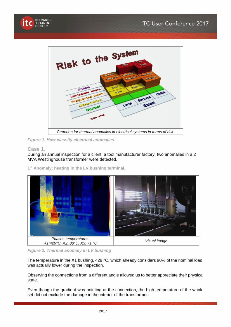
1st Anomaly: heating in the LV bushing terminal.
Phases temperatures:
X1:429°C, X2: 80°C, X3: 71 °C Visual image
Figure 2. Thermal anomaly in LV bushing The temperature in the X1 bushing, 429 °C, which already considers 90% of the nominal load, was actually lower during the inspection. Observing the connections from a different angle allowed us to better appreciate their physical state. Even though the gradient was pointing at the connection, the high temperature of the whole set did not exclude the damage in the interior of the transformer.
2017
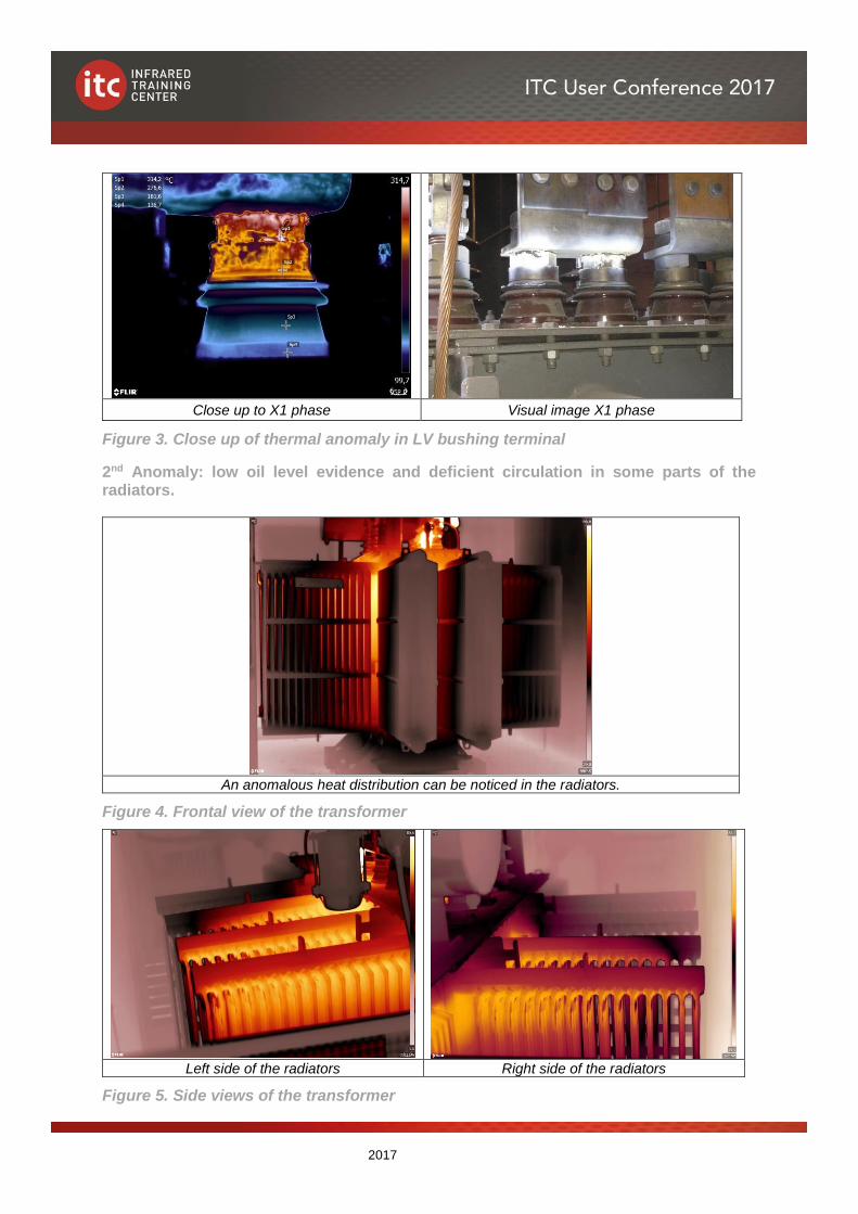
Close up to X1 phase Visual image X1 phase
Figure 3. Close up of thermal anomaly in LV bushing terminal
2nd Anomaly: low oil level evidence and deficient circulation in some parts of the radiators.
An anomalous heat distribution can be noticed in the radiators.
Figure 4. Frontal view of the transformer
Left side of the radiators Right side of the radiators
Figure 5. Side views of the transformer
2017
After investing some time in the plant, it was verified that the substation, where the analysed transformer remains, is located near the forging area. There are two machines with hammers, which caused a strong and repeated vibration on the ground, and this could have affected the transformer.
Severity: Potential hazard of catastrophic failure is determined, such as a short-circuit of great magnitude, even insulating oil ignition, which would affect the whole factory with great material damage and possible victims.
Anomaly reach: A simple failure, operation interruption in the transformer, would affect part of the production in the plant. This is named Sectoral Extent. However, a catastrophic failure, a fire or explosion would trigger out a high risk situation for the workers in the factory, as well as the total production interruption and uncountable material losses. This is known as Global Extent.
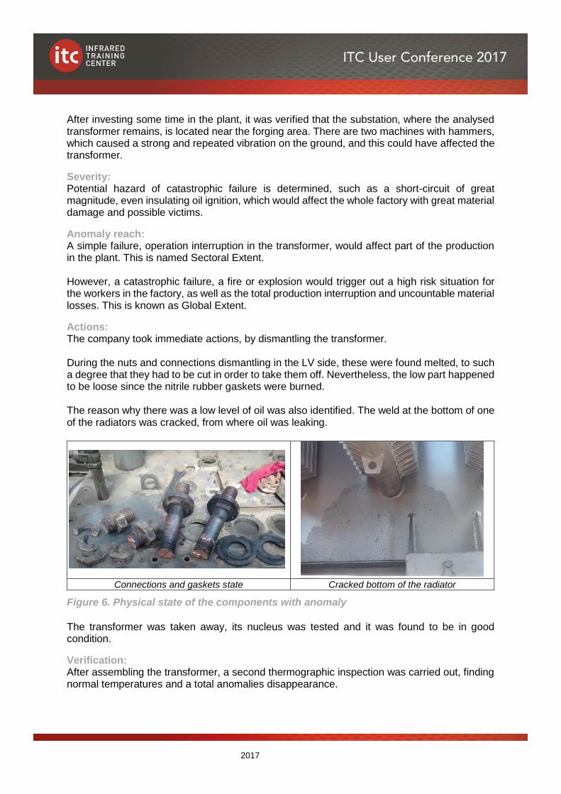
Actions: The company took immediate actions, by dismantling the transformer. During the nuts and connections dismantling in the LV side, these were found melted, to such a degree that they had to be cut in order to take them off. Nevertheless, the low part happened to be loose since the nitrile rubber gaskets were burned. The reason why there was a low level of oil was also identified. The weld at the bottom of one of the radiators was cracked, from where oil was leaking.
Connections and gaskets state Cracked bottom of the radiator
Figure 6. Physical state of the components with anomaly The transformer was taken away, its nucleus was tested and it was found to be in good condition.
Verification: After assembling the transformer, a second thermographic inspection was carried out, finding normal temperatures and a total anomalies disappearance.
2017
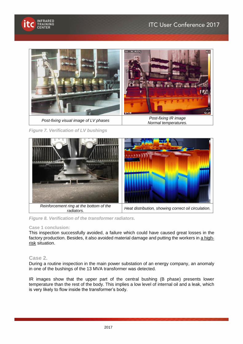
Post-fixing visual image of LV phases Post-fixing IR image
Normal temperatures.
Figure 7. Verification of LV bushings
Reinforcement ring at the bottom of the
radiators. Heat distribution, showing correct oil circulation.
Figure 8. Verification of the transformer radiators.
Case 1 conclusion: This inspection successfully avoided, a failure which could have caused great losses in the factory production. Besides, it also avoided material damage and putting the workers in a high-risk situation.
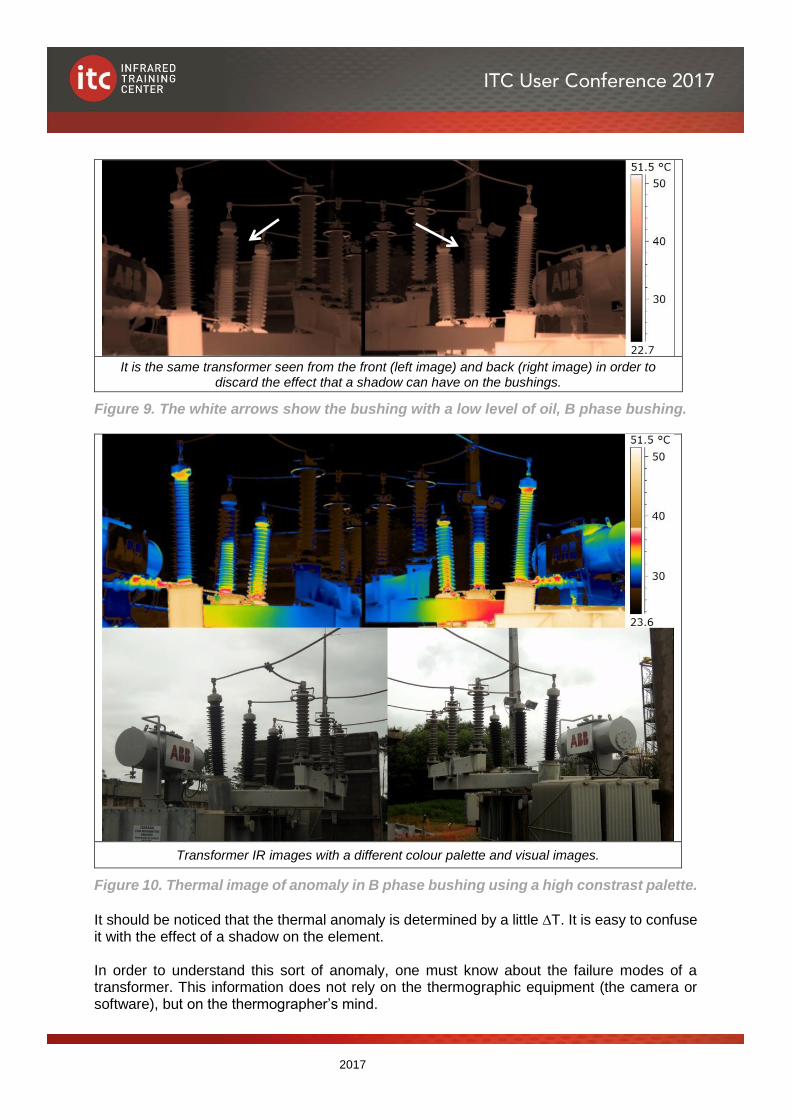
Case 2. During a routine inspection in the main power substation of an energy company, an anomaly in one of the bushings of the 13 MVA transformer was detected. IR images show that the upper part of the central bushing (B phase) presents lower temperature than the rest of the body. This implies a low level of internal oil and a leak, which is very likely to flow inside the transformer’s body.
2017
It is the same transformer seen from the front (left image) and back (right image) in order to
discard the effect that a shadow can have on the bushings.
Figure 9. The white arrows show the bushing with a low level of oil, B phase bushing.
Transformer IR images with a different colour palette and visual images.
Figure 10. Thermal image of anomaly in B phase bushing using a high constrast palette.
It should be noticed that the thermal anomaly is determined by a little T. It is easy to confuse it with the effect of a shadow on the element. In order to understand this sort of anomaly, one must know about the failure modes of a transformer. This information does not rely on the thermographic equipment (the camera or software), but on the thermographer’s mind.
2017
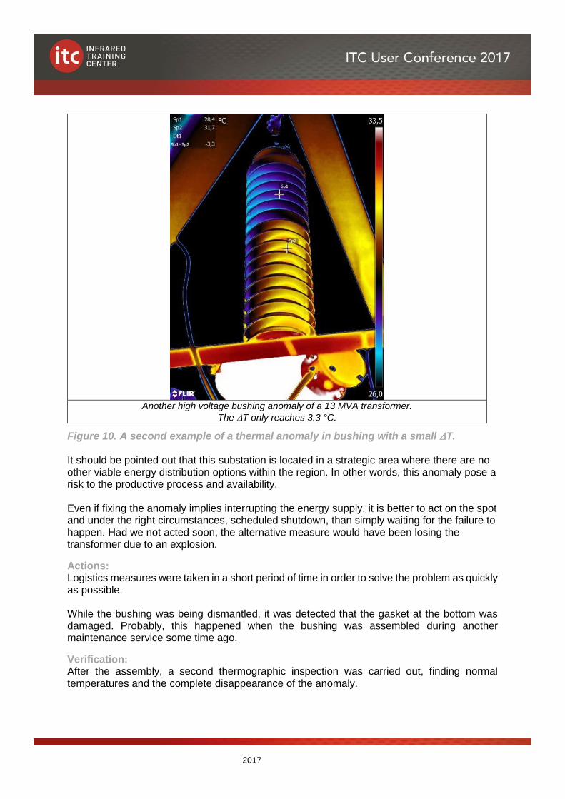
Another high voltage bushing anomaly of a 13 MVA transformer.
The T only reaches 3.3 °C.
Figure 10. A second example of a thermal anomaly in bushing with a small T. It should be pointed out that this substation is located in a strategic area where there are no other viable energy distribution options within the region. In other words, this anomaly pose a risk to the productive process and availability. Even if fixing the anomaly implies interrupting the energy supply, it is better to act on the spot and under the right circumstances, scheduled shutdown, than simply waiting for the failure to happen. Had we not acted soon, the alternative measure would have been losing the transformer due to an explosion.
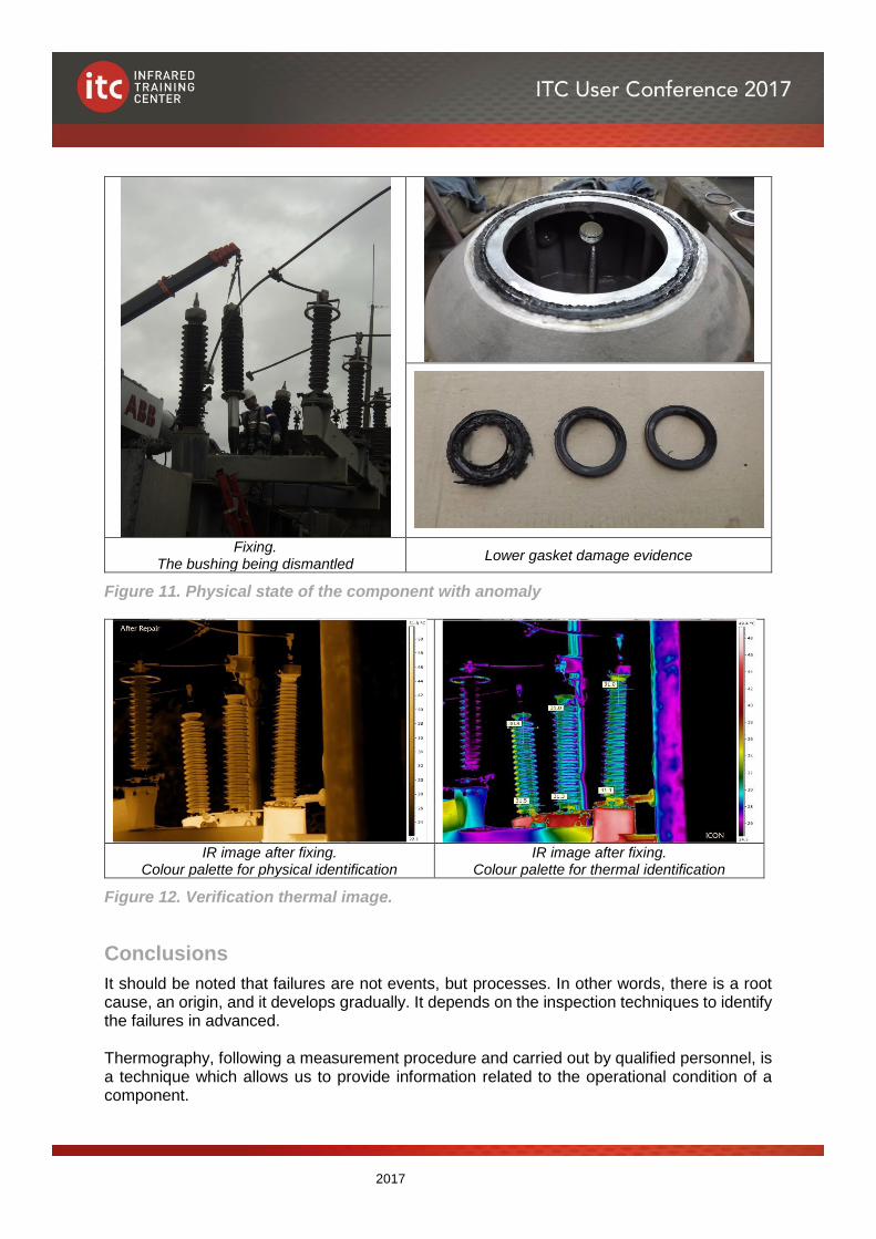
Actions: Logistics measures were taken in a short period of time in order to solve the problem as quickly as possible. While the bushing was being dismantled, it was detected that the gasket at the bottom was damaged. Probably, this happened when the bushing was assembled during another maintenance service some time ago.
Verification: After the assembly, a second thermographic inspection was carried out, finding normal temperatures and the complete disappearance of the anomaly.
2017
Fixing. The bushing being dismantled
Lower gasket damage evidence
Figure 11. Physical state of the component with anomaly
IR image after fixing.
Colour palette for physical identification IR image after fixing.
Colour palette for thermal identification
Figure 12. Verification thermal image.
Conclusions
It should be noted that failures are not events, but processes. In other words, there is a root cause, an origin, and it develops gradually. It depends on the inspection techniques to identify the failures in advanced. Thermography, following a measurement procedure and carried out by qualified personnel, is a technique which allows us to provide information related to the operational condition of a component.
2017
The thermographer’s certification, and their knowledge, not only about the use and management of the instrument (thermographic camera) and the heat and radiation transfer concepts, but also about the failure mechanisms, are vital for the success of the inspection routines and thermography itself. For a company, it is equally important to have an infrared thermographic inspection procedure involving training, criteria and safety requirements. It must be noticed than, the role and responsibilities involved with all aspects of the infrared thermographic inspection procedure, is carried out by a thermographer with a level (category) III certification. Deciding to deal with an anomaly detected with thermography usually implies equipment downtime, handling, and logistics so as to solve the problem, as well as responsibility and a lot of money. Hence, a question for those who have adopted, or plan to use, this technique arises: is the use of inadequate thermographic equipment, or, above all, hiring an unqualified thermographer without any certification or the absence of a proper themographic procedure worth the risk?
Acknowledgements
We would like to thank Eng. José Cristino F. Santos and Eng. Rogério Silva for their important participation and collaboration in the above-mentioned cases. Of course, and one more time, I thank my friend and English teacher, Julio Aguilar Morales, for his invaluable help when writing this paper in English. And thank to Mr. Johann Martin Smith, from Digital Shelf, South Africa, for the final review of the translation.
Source
Images and cases presented are part of the L3IP (Level 3 Integration Package) “Thermography Management in Electrical Systems (Methodology + Software + Proceedings)” – 2003, 2009, 2012, 2016 – Attílio B. Veratti, Erandy Flores Guevara.
Author bios
Eng. Attílio Bruno Veratti started his thermographer career at AGA Infrared Systems in 1979 and worked with AGEMA, Cincinnati Infrared, Raytek and Fluke. As level 3 certified thermographer by ITC and Abendi (Brazilian Association of Non-Destructive Testing and Inspection) he is one of ITC Latin America instructors since 2007. Attílio is also the director of ICON Tecnologia, a consulting and integration company for several customers in the area of development of new applications of thermography, and author of the SIENet (Electrical Management), CTTNet (Thermal Exchange Calculation) and AERNet (Lining Thickness Evaluation) software. Erandy Flores is an electrician-mechanical engineer with 10 years working with thermography, at present she is responsible for thermography services and inspections in SERCA company. Erandy is ITC level 3 certified thermographer and part or the team of instructors form ITC Latin America. Attílio and Erandy dedicate a significant part of their time making divulgation of the innovations and the best practices of thermography in a web site called Termonautas (in Portuguese and Spanish) with more than 6700 registered subscriptions and the Termonautas Facebook with more than 11.000 likes in Latin America.


![First-time detection and identification of the ... · duction) and the results of standard biochemical tests [13]. These latter included niacin test, nitrate reductase test, and susceptibility](https://static.fdocuments.fr/doc/165x107/5f0b62587e708231d43040ee/first-time-detection-and-identification-of-the-duction-and-the-results-of-standard.jpg)