GénéRation & Réseaux Generation netor itG seRies 7--5/7--6 · protection homopolaire...
12
ITG SERIES 7--5 / 7--6 GÉNÉRATION & RÉSEAUX GENERATION & NETWORK ITG SERIES 7--5/7--6 RELAIS DE PROTECTION À MAXIMUM DE COURANT À TEMPS DÉPENDANT OU INDÉPENDANT DEPENDENT OR INDEPENDENT TIME OVERCURRENT RELAYS Les ITG7--5 et 7--6 forment une nouvelle série de relais électroniques se caractérisant par de larges plages de réglage de seuils et de temporisations. Les différents modèles conformes aux normes CEI 255-3 / 255-4, constituent une gamme très complète de relais de protection à maximum de courant à temps constant, inverse, très inverse, extrêmement inverse ou faiblement inverse contre les défauts polyphasés et/ ou à la terre avec seuil haut (ITG7--6) ou sans seuil haut (ITG7--5). Pour la protection homopolaire, 2 versions sont disponibles : • raccordement en connection résiduelle des 3 TC. • raccordement sur tore 100 spires. The ITG7--5 and 7--6 series are a new range of electronic relays which are notable for their wide current and time setting ranges. The various models in conformity with standards IEC 255-3 / 255-4 provide a complete range of overcurrent relays of definite, inverse, very inverse, extremely inverse, slightly inverse time types and/ or earth fault protection relays with high set unit (ITG7--6) or without high set unit (ITG7--5). For earth-fault protection, 2 models are available: • connecting on the residual connection of the 3 ring CT’S. • connecting on 100 turns ring CT. GÉNÉRALITÉS GENERAL
Transcript of GénéRation & Réseaux Generation netor itG seRies 7--5/7--6 · protection homopolaire...

ITG SERIES 7--5 / 7--6
GÉNÉRATION & RÉSEAUXGENERATION & NETWORKITG SERIES 7--5/7--6
Relais de pRotection à maximum de couRant à temps dépendant ou indépendant DepenDent or inDepenDent time overcurrent relays
Les ITG7--5 et 7--6 forment une nouvelle série de relais électroniques se caractérisant par de larges plages de réglage de seuils et de temporisations.
Les différents modèles conformes aux normes CEI 255-3 / 255-4, constituent une gamme très complète de relais de protection à maximum de courant à temps constant, inverse, très inverse, extrêmement inverse ou faiblement inverse contre les défauts polyphasés et/ou à la terre avec seuil haut (ITG7--6) ou sans seuil haut (ITG7--5).
Pour la protection homopolaire, 2 versions sont disponibles :
• raccordement en connection résiduelle des 3 TC.
• raccordement sur tore 100 spires.
The ITG7--5 and 7--6 series are a new range of electronic relays which are notable for their wide current and time set ting ranges.
The various models in conformity with standards IEC 255-3 / 255-4 provide a complete range of overcurrent relays of definite, inverse, very inverse, extremely inverse, slightly in verse time types and/or earth fault protection relays with high set unit (ITG7--6) or without high set unit (ITG7--5).
For earth-fault protection, 2 models are available:
• connecting on the residual connection of the 3 ring CT’S.
• connecting on 100 turns ring CT.
GénéRalités GENERAL

Ils bénéficient de l’expérience exceptionnelle que nous avons acquise depuis de nombreuses années en matière de relais à éléments de mesure statiques dans tous les types d’installations tant en France que dans de nombreux pays du monde et sous toutes conditions climatiques.
Leur boîtier modulaire, type R, peut indifféremment être monté : - soit comme relais séparé : en saillie ou en encastré, - soit par insertion dans un panier rack au standard de 19’’.
Parmi leurs avantages, les relais ITG7--6 possèdent une bonne souplesse d’adaptation en offrant à l’opérateur la faculté d’aiguiller les différentes fonctions vers les unités de sortie selon les schémas les plus répandus. Ils présentent également la possibilité d’éliminer les défauts violents très rapidement par utilisation d’un seuil haut à temps indépendant réglable.
Les différents relais des séries ITG7--5 et ITG7--6 sont définis dans le tableau suivant :
GénéRalitésThey are the direct result of our exceptional experience with relays using static measuring elements, acquired over many years, in all type of installation in France and in many countries throughout the world, and under all climatic conditions.
Their modular case, type R, may be mounted as follows: - either as a separate relay: projecting or flush, - or by insertion into a standard 19” rack cradle.
Amongst its other advantages, the ITG7--6 series of relays have a high level of flexibility as the user can route the relay functions towards the output units according to the widest possible range of combinations. The ability to adjust the high set unit operating time enables the user to ensure that violent faults are eliminated as rapidly as possible.
The va rious relays within the ITG7--5 and 7--6 series are defined in the following table:
GENERAL
Protection
Protection
Fonctions
Functions
Constant
Definite
Courbe caractéristiques temps/courant Time/current characteristics curve
Inverse
Inverse
Très inverse
Very inverse
Extrêmement inverse
Extremely inverse
Faiblement inverse
Slightly inverse
Boîtier
Case
Monophasée ou homopolaire Single phase or earth/ground fault unit
Bi ou triphaséeTwo or three phase
Bi ou triphasée + homopolaire Two or three phase plus earth/ground fault unit
I> t(l>) ou/or Io> t(Io>)
I> t(I>)
I> t(I>)+Io> t(Io>)
ITG7105
ITG7135
ITG7185
ITG7205
ITG7235
ITG7285
ITG7305
ITG7335
ITG7385
ITG7405
ITG7435
ITG7485
ITG7505
ITG7535
ITG7585
R2
R2
R3
Monophasée ou homopolaire Single phase or earth/ground fault
Bi ou triphasée Two or three phase
Biphasée + homopolaire Two phase plus earth/ground fault relay
Bi ou triphasée + homopolaire Two or three phase plus earth/ground fault unit
I> t(l>) + I>> t(Io>)
ou/or Io> t(Io>) Io>> t(Io>>)
I> t(I>) +I>> t(l>>)
I> t(I>) + I>> + Io> t(Io>) + Io>>
I> t(I>) I>> t(I>>) + Io> t(Io>) + Io>> I> t(I>) + I>> + Io> t(Io>) + Io>>
ITG7116
ITG7166
ITG7196
ITGP7196 ITGP7996 phase /phase
ITG7216
ITG7266
ITGP7276
ITG7296
ITGP7296 ITGP7996
homopolaire/earth fault
ITG7316
ITG7366
ITG7396
ITGP7396
ITG7416
ITG7466
ITG7496 ITGT7496
ITGP7496
ITG7516
ITG7566
ITG7596
R2
R2
R4
R3
R4 R4
t(l>>) et t(Io>>) sont temporisés à temps constantt(I>>) and t(lo>>) are time delayed on constant time

pRincipaux aVantaGes• Éléments de mesure statiques à faible consommation sur les
transformateurs de mesure et à grande précision de seuil et de temporisation autorisant une réduction sensible des intervalles de temps dans les schémas de protection sélective.
• Seuil de fonctionnement défini en valeur d’intensité et de temps pour chaque type de courbe à temps inverse, très inverse, extrêmement inverse ou faiblement inverse et non sous forme d’une asymptote à l’axe des temps.
• Indépendance totale des circuits de mesure et de temporisation phases ou homopolaire dans les variantes de protection bi ou triphasée + homopolaire, permettant l’élaboration de deux sélectivités entièrement distinctes.
• Capacité de surcharge : 80 In pendant 1 seconde.
• Relais auxiliaires de sortie à 2 contacts de forte puissance avec voyant mécanique de fonctionnement à réarmement manuel.
• Boîtier modulaire de très grande robustesse et d’encombrement réduit. Plaques signalétiques avec inscriptions symbolisées de type international.
• Protection pour environnements sévères.
• Capacité de stockage à très basse température (vérification par le L.C.I.E. à -57°C).
• Static measuring elements imposing a very low burden on the measuring transformers, and with very high precision on pick-up value and on time-delay, thus permitting a considerable reduction in the time intervals required for completely selective coordination.
• Operating level exactly defined as a value of current and time for each type of curve, either inverse, very in verse, extremely inverse, slightly inverse time and not as an asymptote to the time axis.
• Total independence between the phase and earth-fault measuring elements and time-delay circuits in the models including two or three phases and earth, thus allowing two entirely separate chains of selectivity to be created.
• Overload capacity : 80 In for 1 s.
• Auxiliary output relays with two high-power contacts, and a mechanical, hand-reset operation indicator.
• Very robust: small-volume modular case. Name plate with symbolized inscriptions of the international type.
• Protected against severe environments.
• May be stored at very low temperatures (tests performed by the L.C.I.E. at -57°C).
MAJOR ADVANTAGES
applicationsLes ITG séries 7--5 / 7--6 sont destinés à la protection contre les défauts entre phases ou à la terre, des réseaux de répartition et de distribution d’énergie électrique tant publics qu’industriels.
Quelques exemples d’application sont cités ci-dessous :
liaison par câble ou ligne aérienne entre 2 jeux de barres :
• Réseaux à neutre isolé ITG7-35 ou ITG7166• Réseaux à neutre impédant :
- avec courant homopolaire limité à 25 A et courant capacitif du réseau en aval <3 A ITG7-35 + ITH7111
- avec courant homopolaire compris entre 25 A et 0,8 à 1 In TC ITG7-35 +ITG7-05
- avec courant homopolaire > In TC ITG7-35 ou ITG7166
départ transformateur :
• Réseaux à neutre isolé ITG7-66• Réseaux à neutre impédant :
- avec courant homopolaire limité à 0,8 ou 1 In TC ITG7-66 + ITH7111
- avec courant homopolaire > In TC ITG7-96
protection homopolaire indépendante sur tc bobiné à secondaire 1 a ou 5 a ITG7-05
Nota : une protection à temps inverse contre les défauts à la terre n’est possible que si les courants mis en jeu sont d’une amplitude telle que le temps de fonctionnement soit court et corresponde en pratique à plusieurs fois le seuil affiché. Dans le cas contraire une protection à temps indépendant est préférable (ITH7111 ou ITG7105).
The ITG7--5 / 7--6 series have been specifically designed for the protection of electrical distribution networks and substations (both public utility and industrial) against faults between phases, or from phase to earth.
A few examples of application are given below:
connection by cable or overhead line between 2 busbars:
• Networks with isolated neutral ITG7-35 or ITG7166• Networks with impedance-earthed neutral:
- earth-fault current limited to 25 A and capacitive current of the down-stream network < 3 A ITG7-35 + ITH7111
- with earth-fault currents between 25 A and 0.8 to 1 In of the CT ITG7-35 + ITG7-05
- with earth-fault current > ln CT ITG7-35 or ITG7166
transformer feeder:
• Networks with isolated neutral ITG7-66• Networks with impedance-earthed neutral:
- with earth-fault current limited to 0.8 or 1 In CT ITG7-66 + ITH7111
- with earth-fault current > In CT ITG7-96
independent earth-fault protection, on a wound ct with 1 a or 5 a secondary ITG7-05
Note: Inverse time protection against earth faults is only feasible if the prevailing currents are of an amplitude such that they are at several times the relay pick-up, and times are therefore short. Where this is not the case it is preferable to use definite time relays (ITH7111 or ITG7105).
APPLICATIONS

caRactéRistiQues GénéRales1. Grandeurs d’entrée et de sortie
courant nominal In = 1 A ou 5 A - 50 ou 60 Hz
tension auxiliaire continue
• ITG/ITGT alternative (50 ou 60 Hz)
• ITGP continue
24 V (± 15%); 30 V, 48 V ou 60 V (- 20% +15%);110 V (± 20%); 125 V (-30% +10%); 220 V (±20%)100 V, 110 V, 127 V ou 220 V (-20% +10 %)48 ou 110 ou 125 V (-20% +10%)
consommation :• sur circuit phase• sur circuit homopolaire• sur alimentation auxiliaire en état de veille
- 1 relais excité - 2 relais excités
< 0,2 VA à In< 1 VA à In
Boîtier R2 Boîtier R324 - 30 - 48 Vcc < 3 W < 6 W60 Vcc < 4 W < 8 W110 - 125 Vcc < 7 W < 14 W220 Vcc < 11 W < 22 W100 - 110 Vca < 7,5 VA < 12 VA220 Vca < 14 VA < 28 VA
Ajouter en moyenne 0,5 W ou 0,5 VAAjouter en moyenne 1 W ou 1 VA
transformateurs de courant recommandés : caractéristiques des transformateurs de mesure de phase y compris la charge correspondant à une résistance de boucle de raccordement de 0,1 Ω (In - 5 A) ou de 2 Ω (In - 1 A)
5 VA 5P10
contacts de sortie• tension maximum • courant permanent maximum• pouvoir de fermeture (0,2 s) • pouvoir de coupure :
- CC (L/R = 40 ms) - CA (cos j = 0,4)
2 contacts par unité (2 NO ou 1 NO + 1 NF)600 V5 A10 A
50 W (1 A / 48 Vcc - 0,5 A / 110 Vcc)1250 VA; I < 3 A
Voyants mécaniques A réarmement manuel
signalisation Diode électroluminescente verte de présence de tension auxiliaire s’éteignant au passage du courant au-delà de valeur du seuil
2. Unités de mesure
seuil de fonctionnement de l’unité i> ou lo> 100% de la valeur affichée : ITG71-5 / 71-6110% de la valeur affichée : ITG72-5 / 72-6ITG73-5 / 73-6, ITG74-5 / 74-6, ITG75-51 / 75-6
courbes de fonctionnement :
• courbe inverse, type A de la norme CEI 255-4 (voir figure 2)
• courbe très inverse, type B de la norme CEI 255-4 (voir figure 3)
• courbe extrêmement inverse, type C de la norme CEI 255-4 (voir figure 4)
• courbe faiblement inverse (voir figure 5)
Caractéristiques temps/courant
t(s) = + 0,025
ou ∑ t = valeur du réglage sur face avant du relaistype A : T = 0,14 ∝ = 0,02type B : T = 27 ∝ = 1type C : T = 300 ∝ = 2
t(s) = + 0,025
temps de réponse des unités à seuil haut instantané i>> ou lo>> < 40 ms (à 5 fois le seuil)
temps de retombée des unités seuil bas et seuil haut ~ 40 ms
temps de dépassement balistique (overshoot) pour le seuil haut i>> ou lo>> ~ 15 mspourcentage de dégagement :• unité à seuil bas I> ou lo> • unité à seuil haut I>> ou lo>>
~ 95 %~ 90 %
capacité de surcharge :• gammes phases• gammes homopolaires
80 In - 1 s. 20 In - 3 s, 2 In permanent40 In - 1 s - et In permanent
indice de classe de précision :• relais à temps indépendant :
- sur seuil bas et seuil haut - sur temporisations
• relais à temps dépendant : - sur seuil bas et seuil haut - sur temporisation seuil bas à 10 fois le seuil
- sur temporisation seuil haut
5%5% ou ± 15 ms
5%5% ou ± 15 ms pour relais à temps inverse, très inverse et courbe faiblement inverse 7,5 % ou ± 15 ms pour relais à temps extrêmement inverse5 % ou ± 15 ms
Variations relatives dans les domaines suivants :• température : -5°C à +55°C• fréquence : ± 5 Hz par rapport à FN• tension auxiliaire : dans la plage garantie
SeuilsTemporisations
< 5%< 5% ou ± 10 ms
}

GENERAL CHARACTERISTICS1. Input and output characteristics
Rated current In = 1 A or 5 A - 50 or 60 Hz
Auxiliary supply DC
• ITG/ITGT AC (50 or 60Hz)
• ITGP DC
24 V (± 15%); 30 V, 48 V or 60 V (-20% +15%)110 V (± 20%); 125 V (-30% +10%); 220 V (±20%)100 V, 110 V, 127 V or 220 V (-20 +10%)48 V, 110 V or 125 V (-20% +10%)
Burden:• phase• earth fault• auxiliary state, quiescent state
- 1 relay energised - 2 relays energised
< 0.2 VA at In< 1 VA at In
R2 case R3 case24 - 30 - 48 Vdc < 3 W < 6 W60 Vdc < 4 W < 8 W110 - 125 Vdc < 7 W < 14 W220 Vdc < 11 W < 22 W100 - 110 Vac < 7.5 VA < 12 VA220 Vac < 14 VA < 28 VA
Add approximately 0.5 W or 0.5 VAAdd approximately 1 W or 1 VA
Line current transformers recommended: Line current transformers characteristics allowing an additional wiring loop resistance of 0.1 Ω (In - 5 A) or 2 Ω (In - 1A)
5 VA 5P10
Output contacts• maximum voltage• maximum permanent current• closing capacity (0.2 s)• rupturing capacity:
- DC (L/R = 40 ms) - AC (cos j = 0.4)
2 contacts per unit (2 NO or 1 NO + 1 NC)600 V5 A10 A
50 W (1 A / 48 Vdc - 0.5 A / 110 Vdc)1250 VA; I < 3 A
Mechanical operation indicators With hand reset
Indicator L.E.D. green indicating presence of auxiliary voltage goes out when current is above the unit setting.
2. Measuring units
Operating level of the unit I> or lo> 100% of the setting: ITG71-5 / 71-6110% of the setting: ITG72-5 / 72-6ITG73-5 / 73-6, ITG74-5 / 74-6, ITG75-51 / 75-6
Operating curves:
• inverse curve, IEC 255-4 type A (see figure 2)
• very inverse curve, IEC 255-4, type B (see figure 3)
• extremely inverse curve, IEC 255-4, type C (see figure 4)
• slightly inverse curve (see figure 5)
Time/current characteristics
t(s) = + 0.025
where ∑ t = value of the setting on the front plate of the relaytype A : T = 0.14 ∝ = 0.02type B : T = 27 ∝ = 1type C : T = 300 ∝ = 2
t(s) = + 0.025
Operating time of instantaneous high set units I>> or lo>> < 40 ms (at 5 times setting)
Reset time of high and low set units ~ 40 ms
Overshoot of high set unit I>> or lo>> ~ 15 msDifference between operate and reset levels:• low set unit I> or lo> • high set unit I>> or lo>>
~ 95%~ 90%
Overload:• overcurrent ranges• earth fault ranges
80 In - 1 s; 20 In - 3 s and 2 In permanent40 In - 1 s and In permanent
Precision class:• independent time relays:
- on low set unit and high set unit - on time-delays
• dependent time relays: - on low set unit and high set unit - on time-delay low set at 10 times setting
- on time-delay high set
5%5% or ± 15 ms
5%5% or ± 15 ms for inverse, very inverse and slightly inverse time relays 7.5% or ± 15 ms for extremely inverse time relays5% or ± 15 ms
Maximum errors over the following ranges:• temperature: -5°C at +55°C• frequency: ± 5 Hz comparing to FN• auxiliary voltage:
Operating levelsTime-delays
< 5%< 5% or ± 10 ms
}
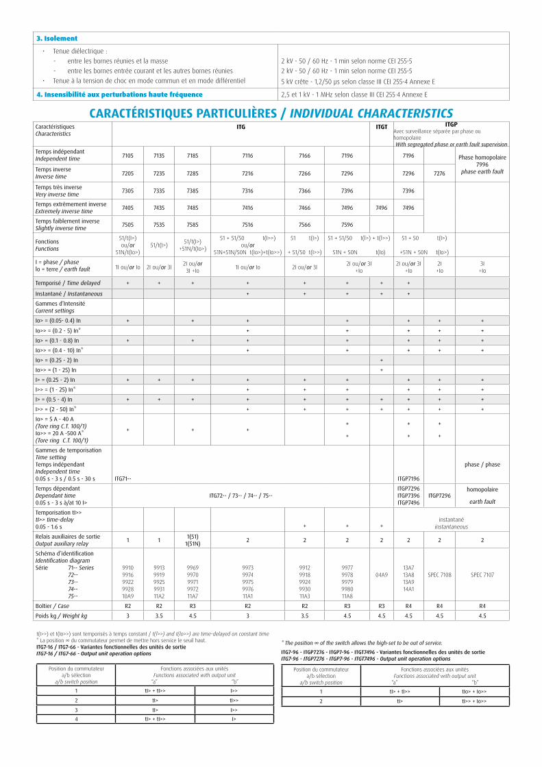
caRactéRistiQues paRticuliÈRes / INDIVIDUAL CHARACTERISTICS
3. Isolement
• Tenue diélectrique : - entre les bornes réunies et la masse - entre les bornes entrée courant et les autres bornes réunies
• Tenue à la tension de choc en mode commun et en mode différentiel
2 kV - 50 / 60 Hz - 1 min selon norme CEI 255-52 kV - 50 / 60 Hz - 1 min selon norme CEI 255-55 kV crête - 1,2/50 µs selon classe III CEI 255-4 Annexe E
4. Insensibilité aux perturbations haute fréquence 2,5 et 1 kV - 1 MHz selon classe III CEI 255·4 Annexe E
CaractéristiquesCharacteristics
itG itGt itGpAvec surveillance séparée par phase ou homopolaireWith segregated phase or earth fault supervision
Temps indépendant Independent time 7105 7135 7185 7116 7166 7196 7196 Phase homopolaire
7996phase earth faultTemps inverse
Inverse time 7205 7235 7285 7216 7266 7296 7296 7276
Temps très inverseVery inverse time 7305 7335 7385 7316 7366 7396 7396
Temps extrêmement inverseExtremely inverse time 7405 7435 7485 7416 7466 7496 7496 7496
Temps faiblement inverseSlightly inverse time 7505 7535 7585 7516 7566 7596
FonctionsFunctions
51/t(I>)ou/or
51N/t(Io>)51/t(I>) 51/t(I>)
+51N/t(Io>)
51 + 51/50 t(I>>)ou/or
51N+51N/50N t(Io>)+t(Io>>)
51 t(I>)
+ 51/50 t(I>>)
51 + 51/50 t(l>) + t(l>>)
51N + 50N t(Io)
51 + 50 t(I>)
+51N + 50N t(Io>)
I = phase / phaselo = terre / earth fault 1I ou/or Io 2I ou/or 3I 2I ou/or
3I +Io 1I ou/or Io 2I ou/or 3I 2I ou/or 3I+Io
2I ou/or 3I+Io
2I+Io
3I+Io
Temporisé / Time delayed + + + + + + + +
Instantané / Instantaneous + + + + +
Gammes d’IntensitéCurrent settings
Io> = (0.05- 0.4) In + + + + + + +
Io>> = (0.2 - 5) In* + + + + +
Io> = (0.1 - 0.8) In + + + + + + +
Io>> = (0.4 - 10) In* + + + + +
Io> = (0.25 - 2) In +
Io>> = (1 - 25) In +
I> = (0.25 - 2) In + + + + + + + + +
I>> = (1 - 25) In* + + + + + +
I> = (0.5 - 4) In + + + + + + + + + +
I>> = (2 - 50) In* + + + + + + +
Io> = 5 A - 40 A(Tore ring C.T. 100/1)Io>> = 20 A -500 A*(Tore ring C.T. 100/1)
+ + ++
+
+
+
+
+
Gammes de temporisationTime settingTemps indépendantIndependent time0.05 s - 3 s / 0.5 s - 30 s ITG71-- ITGP7196
phase / phase
Temps dépendantDependant time0.05 s - 3 s à/at 10 I>
ITG72-- / 73-- / 74-- / 75--ITGP7296ITGP7396ITGP7496
ITGP7296homopolaire
earth fault
Temporisation tI>>tI>> time-delay0.05 - 1.6 s + + +
instantané
instantaneous
Relais auxiliaires de sortieOutput auxiliary relay 1 1 1(51)
1(51N) 2 2 2 2 2 2 2
Schéma d’identificationIdentification diagramSérie 71-- Series 72-- 73-- 74-- 75--
991099169922992810A9
991399199925993111A2
996999709971997211A7
997399749975997611A1
991299189924993011A3
997799789979998011A8
04A913A713A813A914A1
SPEC 7108 SPEC 7107
Boîtier / Case R2 R2 R3 R2 R2 R3 R3 R4 R4 R4
Poids kg / Weight kg 3 3.5 4.5 3 3.5 4.5 4.5 4.5 4.5 4.5
t(I>>) et t(Io>>) sont temporisés à temps constant / t(l>>) and t(lo>>) are time-delayed on constant time* La position ∞ du commutateur permet de mettre hors service le seuil haut.ITG7-16 / ITG7-66 - Variantes fonctionnelles des unités de sortieitG7-16 / itG7-66 - output unit operation options
Position du commutateura/b sélection
a/b switch position
Fonctions associées aux unités Functions associated with output unit
“a” “b”
1 tI> + tI>> I>>
2 tI> tI>>
3 tI> I>>
4 tI> + tI>> I>
* The position ∞ of the switch allows the high-set to be out of service.
ITG7-96 - ITGP7276 - ITGP7-96 - ITGT7496 - Variantes fonctionnelles des unités de sortieitG7-96 - itGp7276 - itGp7-96 - itGt7496 - output unit operation options
Position du commutateura/b sélection
a/b switch position
Fonctions associées aux unitésFunctions associated with output unit
“a” “b”
1 tI> + tI>> tIo> + Io>>
2 tI> tI>> + Io>>
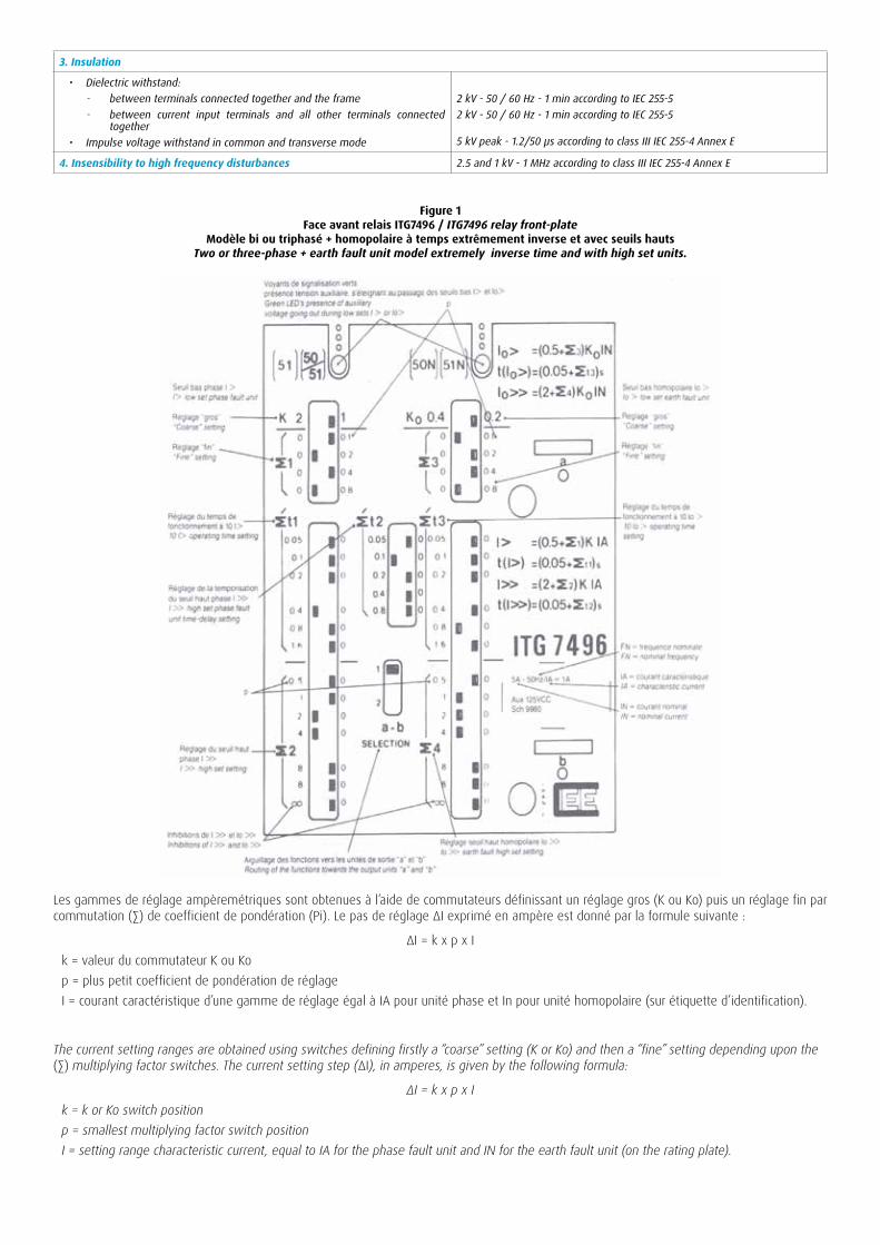
Figure 1Face avant relais itG7496 / ITG7496 relay front-plate
modèle bi ou triphasé + homopolaire à temps extrêmement inverse et avec seuils hautsTwo or three-phase + earth fault unit model extremely inverse time and with high set units.
3. Insulation
• Dielectric withstand: - between terminals connected together and the frame - between current input terminals and all other terminals connected
together• Impulse voltage withstand in common and transverse mode
2 kV - 50 / 60 Hz - 1 min according to IEC 255-52 kV - 50 / 60 Hz - 1 min according to IEC 255-5
5 kV peak - 1.2/50 µs according to class III IEC 255-4 Annex E
4. Insensibility to high frequency disturbances 2.5 and 1 kV - 1 MHz according to class III IEC 255-4 Annex E
Les gammes de réglage ampèremétriques sont obtenues à l’aide de commutateurs définissant un réglage gros (K ou Ko) puis un réglage fin par commutation (∑) de coefficient de pondération (Pi). Le pas de réglage ΔI exprimé en ampère est donné par la formule suivante :
ΔI = k x p x Ik = valeur du commutateur K ou Kop = plus petit coefficient de pondération de réglageI = courant caractéristique d’une gamme de réglage égal à IA pour unité phase et In pour unité homopolaire (sur étiquette d’identifica tion).
The current setting ranges are obtained using switches defining firstly a “coarse’’ setting (K or Ko) and then a “fine” setting depending upon the (∑) multiplying factor switches. The current setting step (ΔI), in amperes, is given by the following formula:
ΔI = k x p x Ik = k or Ko switch positionp = smallest multiplying factor switch positionI = setting range characteristic current, equal to IA for the phase fault unit and IN for the earth fault unit (on the rating plate).

Figure 2 itG72-5 / 72-6 - itGp72-6 - courbes à temps inverse type a - cei 255-4
Inverse time curves type A - IEC 255-4

Figure 3 itG73-5 / 73-6 - itGp7396 - courbes à temps très inverse type B - cei 255-4
Very inverse time curves type B - IEC 255-4

Figure 4itG74-5 / 74-6 - itGp7496 - courbes à temps extrêmement inverse type c Extremely inverse time curves type C - IEC 255-4
Figure 5itG75-5 / 75-6 - courbes à temps faiblement inverse
Slightly inverse time curves

Fonctionnement / OPERATION
Exemples de schémas de fonctionnement simplifié et de raccordementExamples of simplified operation and connection diagrams
Figure 6 - itG7105
Figure 7 - itG7266
FA88
3A
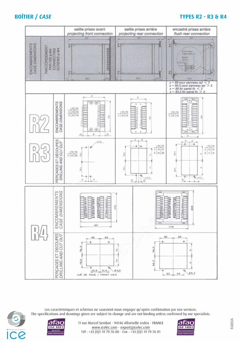
BoÎtieR / CASE tYpes R2 - R3 & R4